

Page 1

Remote Automation Solutions
Part Number D301743X012
June 2019
Tank Manager User Manual
(for ROC800-Series and FloBoss™ 107
Controllers)
Page 2

Tank Manager User Manual (for ROC800-Series and FloBoss 107)
ii Revised June-2019
System Training
A well-trained workforce is critical to the success of your operation. Knowing how to correctly install,
configure, program, calibrate, and trouble-shoot your Emerson equipment provides your engineers
and technicians with the skills and confidence to optimize your investment. Remote Automation
Solutions offers a variety of ways for your personnel to acquire essential system expertise. Our fulltime professional instructors can conduct classroom training at several of our corporate offices, at
your site, or even at your regional Emerson office. You can also receive the same quality training via
our live, interactive Emerson Virtual Classroom and save on travel costs. For our complete schedule
and further information, contact the Remote Automation Solutions Training Department at 800-3388158 or email us at education@emerson.com.
Page 3

Tank Manager User Manual (for ROC800-Series and FloBoss 107)
Revised June-2019 Contents iii
Contents
Chapter 1 – Introduction 1
1.1 Scope and Organization ..................................................................................................................... 1
1.2 Product Overview ............................................................................................................................... 2
1.2.1 Definition of Terms ............................................................................................................... 2
1.3 Program Features .............................................................................................................................. 5
1.3.1 License Key.......................................................................................................................... 7
Chapter 2 – Installation 9
2.1 Installing the License Key .................................................................................................................. 9
2.1.1 Installing the License Key for the ROC800 .......................................................................... 9
2.1.2 Installing a License Key for the FB107 .............................................................................. 10
2.1.3 Verifying the License Key Installation (for ROC800) ......................................................... 11
2.2 Installing the Program ...................................................................................................................... 12
2.3 Installing the Optional User Displays (for FB107) ............................................................................ 17
2.3.1 Installing the Haul Log Viewer Display .............................................................................. 17
2.3.2 Installing the Hauler Database Display .............................................................................. 21
2.3.3 Installing the Enumerated Lists Display ............................................................................. 24
2.4 MPU Loading Threshold (for ROC800) ............................................................................................ 27
Chapter 3 – Configuration 29
3.1 PMTM Units ...................................................................................................................................... 31
3.1.1 PMTM Units – Units Tab .................................................................................................... 32
3.1.2 PMTM Units – Advance Settings Tab ................................................................................ 34
3.2 PMTM Tank Manager ...................................................................................................................... 37
3.2.1 PMTM Tank Manager – Liquids Data Tab ......................................................................... 38
3.2.2 PMTM Tank Manager – Liquids Configuration Tab ........................................................... 42
3.2.3 PMTM Tank Manager – Tank Strapping Tab .................................................................... 52
3.2.4 PMTM Tank Manager – Alarms and Rollovers Tab........................................................... 55
3.3 PMTM Allocated Well Values ........................................................................................................... 59
3.3.1 PMTM Allocated Well Values – Allocation/Production Values Tab ................................... 60
3.3.2 PMTM Allocated Well Values – Allocation/Production Config Tab .................................... 64
3.4 PMTM Haul Log Viewer ................................................................................................................... 68
3.4.1 PMTM Haul Log Viewer – Haul Log Overview Tab ........................................................... 69
3.4.2 PMTM Haul Log Viewer – Detailed Viewer and SCADA Pickup Tab ................................ 69
3.5 PMTM Load Out ............................................................................................................................... 71
3.5.1 PMTM Load Out – Load Out Operate Tab ........................................................................ 72
3.5.2 PMTM Load Out – Load Out Values/Stats Tab ................................................................. 79
3.5.3 PMTM Load Out – Measurement Configuration Tab ......................................................... 82
3.5.4 PMTM Load Out – Load Out Configuration Tab ................................................................ 89
3.5.5 PMTM Load Out – Hauling Screens Configuration Tab .................................................... 92
3.5.6 PMTM Load Out – Inter-Tank Transfer Tab ...................................................................... 99
3.6 PMTM Hauler Data Base ............................................................................................................... 100
3.7 PMTM Enumerated Lists ................................................................................................................ 102
3.8 Saving the Configuration ................................................................................................................ 105
Page 4

Tank Manager User Manual (for ROC800-Series and FloBoss 107)
iv Contents Revised June-2019
Chapter 4 – Reference 107
4.1 Point Type 60/187: PMTM Units ................................................................................................... 108
4.2 Point Type 196/178: PMTM Tanks and Aggregates ..................................................................... 113
4.3 Point Type 197/179: PMTM Wells ................................................................................................ 128
4.4 Point Type 198/180: PMTM Haul Logs ......................................................................................... 137
4.5 Point Type 199/181: PMTM Haul Ticketing .................................................................................. 149
4.6 Point Type 230/182: PMTM Fluid Properties ................................................................................ 158
4.7 Point Type 231/183: PMTM Load Outs ......................................................................................... 165
4.8 Point Type 232/184: PMTM Hauler Database .............................................................................. 185
4.9 Point Type 233/185: PMTM Haul Current Values ......................................................................... 186
4.10 Point Type 234: PMTM Simulator ................................................................................................. 202
Appendix A – Log Viewer Utility 207
Appendix B – Retrieving the Haul Logs via SCADA 211
Page 5

Tank Manager User Manual (for ROC800-Series and FloBoss 107)
Revised June-2019 Introduction 1
Chapter 1 – Introduction
Caution
When implementing control using this product, observe best industry
practices as suggested by applicable and appropriate environmental,
health, and safety organizations. While this product can be used as a
safety component in a system, it is NOT intended or designed to be the
ONLY safety mechanism in that system.
This chapter describes the structure of this manual and presents an
overview of the Tank Manager program for the ROC800-Series
(ROC800) and FloBoss™ 107 (FB107) devices.
1.1 Scope and Organization
This document serves as the user manual for the Tank Manager
program, which is intended for use in either a ROC800 or FB107.
This manual describes how to install and configure the Tank Manager
program (referred to as the “program” throughout the rest of this
manual). You access and configure the program using ROCLINK™ 800
Configuration Software (version 2.41 or greater) loaded on a personal
computer (PC) running Microsoft® Windows® 7 (32-bit or 64-bit).
The chapters in this manual provide information in a sequence
appropriate for first-time users. Once you become familiar with the
procedures and the software running in a ROC800 or FB107, the
manual becomes a reference tool.
This manual has the following major sections:
▪ Chapter 1 – Introduction
▪ Chapter 2 – Installation
▪ Chapter 3 – Configuration
▪ Chapter 4 – Reference
▪ Appendix A – Log Viewer Utility
▪ Appendix B – Retrieving the Haul Logs via SCADA
This manual assumes that you are familiar with the ROC800 or FB107
and its configuration. For more information, refer to the following
manuals:
▪ FloBoss™ 107 Flow Manager Instruction Manual (Part
D301232X012)
▪ ROC800 Remote Operations Controller Instruction Manual (Part
D301217X012)
▪ ROCLINK 800 Configuration Software User Manual (for FloBoss™
107) (Part D301249X012)
▪ ROCLINK 800
™
Configuration Software User Manual (for
ROC800-Series) (Part D301250X012)
Page 6

Tank Manager User Manual (for ROC800-Series and FloBoss 107)
2 Introduction Revised June-2019
1.2 Product Overview
The Production Manager Tank Manager (PMTM) program or simply
Tank Manager is designed to function either as a stand-alone product or
as part of Remote Automation Solutions’ SmartProcess
™
Oil and Gas
Application suite. Tank Manager uses a level-based measurement to
manage volumetric inventory, calculate well head production, and
measure truck-hauled volumes. It calculates net standard volume (NSV)
for the hauled hydrocarbon fluid using API Chapter 11, 2004
Calculations (11.1.6.1 and 11.1.6.2) for crude oil. The Production
Manager Tank Manager also includes options for API Chapter 18.2
(2016) compliant custody transfer methodology and calculations.
The program provides SCADA-friendly reporting to document hauling
events, and hosts an HMI interface for truck drivers. The program
supports both metered and level-based hauling measurement, applying
NSV correction to the primary measurement. It provides safety/control
interlocks to automate loading valves or pumps.
The program can calculate inferred production during hauling, provide
“seal on” and “seal off” tracking, and display a variety of tank
production statistics in user-friendly displays.
A version of the Tank Manager program is available with a built-in
simulator for manipulating tank levels, meter rates, and conducting a
haul. This version is intended only for labs or testing, and is not
applicable in a field installation.
Caution
All the versions of Tank Manager include a watchdog counter that
can be used to validate the execution of the program logic. This is a
parameter which continuously increments (1 count per second) while
the program is running. If the value of the parameter does not
change, then the program is not executing logic.
You can monitor this parameter using an external system, such as a
SCADA host system, or an FST within the device, to validate
operation. For the ROC800, this is Point Type 197, Parameter 125. For
the FB107, this is Point Type 179, Parameter 125. For more
information, see the definition for this parameter in Chapter 4.
1.2.1 Definition of Terms
The business of tank management and hauling has its own vocabulary.
Following are terms frequently used in hauling, which appear in the
Tank Manager application.
Term
Definition
API Chapter 11.1.6.1 and 2
The standard for calculating crude oil
measurement. Both the Tank Manager
application and the 800L programs use the
2004 version of these calculations.
Page 7

Tank Manager User Manual (for ROC800-Series and FloBoss 107)
Revised June-2019 Introduction 3
Term
Definition
API Chapter 18.2
The standard used to in part to determine the
program behavior for hauls from the load-out
terminals. The full title of the standard is
Custody Transfer of Crude Oil from Lease
Tanks using Alternative Measurement
Methods.
Average CTL of Base ALT
Correction factor of density recorded at time of
“Grind” to standard temperature.
Average CTL of Observed
Base
Correction factor of fluid temperature
compared to standard temperature.
Base Conditions
The standard temperature and pressure
values defined in the contract, which are
typically 60 degrees Fahrenheit and 14.73
PSIA (also as defined by API).
Basic Sediment and
Water (BS&W)
The non-oil components in a tank, which tends
to be a residual, typically defined as a
percentage (%) of volume.
Closeout
The process of final verification by the truck
driver of the information entered and/or
recorded during the truck haul, which becomes
the recorded haul log audit trail.
Correction for the effect
of Temperature on Liquid
(CTL)
The average of the temperature measured,
compared to the standard temperature.
Correction for the effect
of Temperature on Steel
(CTS)
A correction routine used to compensate for
the expansion of the tank shell material (and
therefore the tank volume), due to the effect of
temperature.
Divert Valve
A 3-way valve with 1 inlet, and 2 outlets. Used
commonly in LACT measurement, if the
sediment and water percentage for a fluid
being transferred exceeds the required
tolerance, the divert valve is activated, and
transfers oil back to a tank.
Equalized Tanks
A group of identically sized tanks for a single
phase liquid application with a common level
measurement used to handle larger capacities.
Flow/Tank Volume
Reconciliation
Specific to the Tank Manager application, this
is the ability to provide and report dual,
independent measurements (flow and tank
volume) of haul events. This process provides
a basis for verification when self-proving of
flow custody transfer is not available.
Gas/Liquids Ratio (GLR)
A method to estimate liquid production rate,
based on measured gas production rate.
Gauging; Gauging the
Tank
The manual or automated process to measure
the current level in the tank.
Grind; Grinding the Tank
The manual measurement technique for
determining the percentage (%) of BS&W in a
tank, as well as the density measurement. This
process requires a recorded temperature of
sample.
Page 8

Tank Manager User Manual (for ROC800-Series and FloBoss 107)
4 Introduction Revised June-2019
Term
Definition
Gross Volume
The total volume of the liquid in the tank at
current ambient and fluid temperature.
Inferred Production
A method for estimating production flow into a
tank during a hauling event when a direct
measurement (such as using GLR) is not
available.
Interface
The intermediate level measurement at the
separation point between oil and water in the
tank.
Leased Automatic
Custody Transfer (LACT)
An automated system for measuring,
sampling, and transferring oil from a lease
location into a pipeline.
Merchantable
Refers to the suitability of oil for purchase or
sale. Oil which has unsuitable characteristics
(such as high sediment and water content or
high amounts of H2S) is said to be nonmerchantable.
Net Standard Volume
(NSV)
The corrected volume of oil at Base
Conditions, less BS&W volume, using the API
Chapter 11 standard.
Preset
A predefined volume of liquid for the truck
haul.
Seal Off/Seal On Tags
A single-use, metal, pre-stamped, numerical
tag connected to the block valve to retain an
audit trail of hauling events. The tag number is
recorded and removed as a Seal-Off Tag at
the beginning of the haul, and a new tag
number is recorded and installed as a Seal-On
Tag at closeout.
Shrinkage
The difference between the maximum volume
(recorded prior to a haul event) and the
volume at the start of the haul process
(recorded on per-haul event basis). Causes of
shrinkage can include gas vaporing or tank
waves.
Strapping
Also known as tank calibration, tank strapping
is the ability to convert a tank level value (fluid
height) to an associated volume.
Tank Aggregate
A group of tanks managing the production of
water and/or oil produced from one or several
wells.
Tank Instance
Specific to the Tank Manager application, this
term defines the number of physical tanks
and/or groups of tanks. For example, three
equalized tanks count as a single Tank
Instance, while an aggregate of three tanks
being managed independently as well as a
collective group, count as four Tank Instances.
Page 9

Tank Manager User Manual (for ROC800-Series and FloBoss 107)
Revised June-2019 Introduction 5
Term
Definition
Tank Strapping
Volumetric equivalent of measured level,
based on the cross-sectional dimensions of a
tank at different levels. Used for non-cylindrical
tanks or where the weight of the liquid causes
deflection of the tank sides.
Tank Transfer
A reportable movement of liquid between
tanks.
Truck Haul
The custody transfer event where the liquids
are loaded onto a truck.
Turndown
When a haul from a tank is started, but is
unable to complete for reasons such as
equipment failure or non-merchantable oil.
The rejected haul is said to be “turned down”.
Unitized Tanks
A predefined/pre-assigned tank piped from the
well(s) and separation train.
1.3 Program Features
Program Variants
The Tank Manager program is distributed on one CD, which
contains all programs for both the ROC800 and FB107 platforms.
The program version you install depends on the functionality you
require, the number of licenses you have purchased, and the number
of tanks and wells you need to support.
ROC800
The following table shows the number of tanks and wells each
program supports:
Program Name
Supported Features
PMTM_V409_xx_8t_SIM.tar
Supports up to 8 tanks and a simulation program.
Note: The simulation program is not intended for
installation on an operating tank farm.
PMTM_V409_xx_8t4w.tar
Supports up to 8 tanks and 4 wells.
PMTM_V409_xx_16t_SIM.tar
Supports up to 16 tanks and a simulation program.
Note: The simulation program is not intended for
installation on an operating tank farm.
PMTM_V409_xx_16t8w.tar
Supports up to 16 tanks and 8 wells.
PMTM_V409_xx_24t_SIM.tar
Supports up to 24 tanks and a simulation program.
Note: The simulation program is not intended for
installation on an operating tank farm.
PMTM_V409_xx_24t12w.tar
Supports up to 24 tanks and 12 wells.
PMTM_V409_xx_32t_SIM.tar
Supports up to 32 tanks and a simulation program.
Note: The simulation program is not intended for
installation on an operating tank farm.
PMTM_V409_xx_32t12w.tar
Supports up to 32 tanks and 12 wells.
PMTM_V409_xx_40t_SIM.tar
Supports up to 40 tanks and a simulation program.
Note: The simulation program is not intended for
installation on an operating tank farm.
PMTM_V409_xx_40t12w.tar
Supports up to 40 tanks and 12 wells.
Page 10

Tank Manager User Manual (for ROC800-Series and FloBoss 107)
6 Introduction Revised June-2019
FloBoss 107
The following table shows the number of tanks and wells the FB107
program supports:
Program Name
Supported Features
PMTM_v409_xx_7.bin
Supports up to 8 tanks and 4 wells.
Version 4.09 of the Tank Manager program is compatible with firmware
version 3.61 of the ROC800, firmware version 1.41 of the ROC800L,
firmware version 1.70 of the FB107, and with version 2.41 (or greater)
of ROCLINK 800 Configuration software and requires firmware
version 1.20 of the keypad display.
Program specifics include:
File Name
Target Unit/
Version
User Defined
Point (UDP)
Flash Used
(in bytes)
DRAM Used
(in bytes)
ROCLINK 800
Version
Display
Number
PMTM_V409_xx_
8t4w.tar
ROC800 v3.61
60, 196, 197,
198, 199, 230,
231, 232, 233
496,248
503,808
2.41
60, 196, 197,
198, 231, 232,
233
PMTM_V409_xx_
8t_SIM.tar
ROC800 v3.61
60, 196, 197,
198, 199, 230,
231, 232, 233,
234
508,376
557,056
2.41
60, 196, 197,
198, 231, 232,
233
PMTM_V409_xx_
16t8w.tar
ROC800 v3.61
60, 196, 197,
198, 199, 230,
231, 232, 233
495,477
548,864
2.41
60, 196, 197,
198, 231, 232,
233
PMTM_V409_xx_
16t_SIM.tar
ROC800 v3.61
60, 196, 197,
198, 199, 230,
231, 232, 233,
234
507,819
565,248
2.41
60, 196, 197,
198, 231, 232,
233
PMTM_v409_xx_
24t12w.tar
ROC800 v3.61
60, 196, 197,
198, 199, 230,
231, 232, 233
495,550
602,112
2.41
60, 196, 197,
198, 231, 232,
233
PMTM_V409_xx_
24t_SIM.tar
ROC800 v3.61
60, 196, 197,
198, 199, 230,
231, 232, 233,
234
508,152
618,496
2.41
60, 196, 197,
198, 231, 232,
233
PMTM_v409_xx_
32t12w.tar
ROC800 v3.61
60, 196, 197,
198, 199, 230,
231, 232, 233
495,594
643,072
2.41
60, 196, 197,
198, 231, 232,
233
PMTM_V409_xx_
32t_SIM.tar
ROC800 v3.61
60, 196, 197,
198, 199, 230,
231, 232, 233,
234
508,095
663,552
2.41
60, 196, 197,
198, 231, 232,
233
PMTM_v409_xx_
40t12w.tar
ROC800 v3.61
60, 196, 197,
198, 199, 230,
231, 232, 233
495,540
688,128
2.41
60, 196, 197,
198, 231, 232,
233
Page 11

Tank Manager User Manual (for ROC800-Series and FloBoss 107)
Revised June-2019 Introduction 7
File Name
Target Unit/
Version
User Defined
Point (UDP)
Flash Used
(in bytes)
DRAM Used
(in bytes)
ROCLINK 800
Version
Display
Number
PMTM_V409_xx_
40t_SIM.tar
ROC800 v3.61
60, 196, 197,
198, 199, 230,
231, 232, 233,
234
508,325
704,512
2.41
60, 196, 197,
198, 231, 232,
233
PMTM_v409
_xx_7.bin
FB107 v1.70
178, 179, 180,
181, 182, 183,
184, 185, 187
490,236
32,768
2.41
79, 80, 81, 83
Note: Depending on the version you install, the flash memory and
DRAM usages may be less.
For information on viewing the memory allocation of user programs,
refer either to the ROCLINK 800 Configuration Software User Manual
(for ROC800-Series) (Part D301250X012) or the ROCLINK 800
Configuration Software User Manual (for FloBoss 107) (Part
D301249X012).
1.3.1 License Key
License keys, when matched with valid license codes, grant access to
applications such as the Tank Manager program.
For ROC800, the term “license key” refers to the physical piece of
hardware that can contain up to seven different licenses (refer to
Figure 1-1). Each ROC800 can have none, one, or two license keys
installed. If you remove a license key after enabling an application, the
firmware disables the task from running. This prevents unauthorized
execution of protected applications in a ROC800.
DOC0422A
J1
U1
Figure 1-1. License Key
Note: Each PMTM license supports up to 8 tanks and 4 wells.
Licenses are delivered on a standard ROC800 license key.
Consult with your Remote Automation Solutions sales
representative to obtain the appropriate number of licenses for
your application.
Page 12

Tank Manager User Manual (for ROC800-Series and FloBoss 107)
8 Introduction Revised June-2019
For FB107, the software licenses are distributed via a secure SafeNet®
Sentinel™ USB drive (“license key”). You must install one license key,
PMTM, to use the Tank Manager program.
Page 13

Tank Manager User Manual (for ROC800-Series and FloBoss 107)
Revised June-2019 Installation 9
Chapter 2 – Installation
This section provides instructions for installing the Tank Manager
program. Read Section 1.3 of this manual for program requirements.
2.1 Installing the License Key
The Tank Manager application requires a license to function. This
section provides instructions for installing the license into the flash
memory on the ROC800 or the FB107.
2.1.1 Installing the License Key for the ROC800
Caution
Failure to exercise proper electrostatic discharge precautions, such as
wearing a grounded wrist strap may reset the processor or damage
electronic components, resulting in interrupted operations.
When working on units located in a hazardous area (where explosive
gases may be present), make sure the area is in a non-hazardous state
before performing these procedures. Performing these procedures in a
hazardous area could result in personal injury or property damage.
To install a license key:
1. Remove power from the ROC800.
2. If necessary, remove the wire channel cover.
3. Unscrew the screws from the Central Processing Unit (CPU)
faceplate.
4. Remove the CPU faceplate.
5. Place the license key in the appropriate terminal slot (P4 or P6) in
the CPU (refer to Figure 2-1).
Figure 2-1. License Key Installation
6. Press the license key into the terminal until it is firmly seated (refer
to Figure 2-1).
7. Re-attach the CPU faceplate.
8. Re-attach the screws on the CPU faceplate.
9. If necessary, re-attach the wire channel cover.
10. Restore power to the ROC800.
11. Proceed to Section 2.1.3 to verify your license keys.
Page 14

Tank Manager User Manual (for ROC800-Series and FloBoss 107)
10 Installation Revised June-2019
2.1.2 Installing a License Key for the FB107
Program licenses for the FB107 are stored on a secure SafeNet®
Sentinel™ USB license key. To install a license on the FB107:
1. Insert the USB license key in a USB port on your PC.
2. Select Utilities > License Key Administrator > Transfer Between
DEVICE and KEY from the ROCLINK 800 menu bar. The
Transfer Licenses Between a Device and a Key screen displays.
Figure 2-2. Transfer Licenses Between a Device and a Key
Note: This screen has three sections. The upper portion (Licenses on
Device) shows any software licenses installed on the FB107.
The middle portion (Licenses on Key) shows software licenses
on the license key. The lower portion of the screen (License Key
Event Log) provides a rolling log of the last eight events related
to this license key.
3. Select the key-based license you want to transfer to the FB107
(PMTM, as shown in Figure 2-2).
4. Click Move to Device. ROCLINK moves the license from the key
to the FB107 and updates the screen.
Page 15

Tank Manager User Manual (for ROC800-Series and FloBoss 107)
Revised June-2019 Installation 11
Figure 2-3. License Installed (FB107)
Note: An FB107 can hold up to six different licenses, although you can
install only one instance of each license on the FB107. When
you click Move to Device, ROCLINK 800 moves only one
instance of the license onto the FB107 and automatically
decreases the total number of licenses on the USB drive by one
(if it contains more than one).
5. Verify that the license name now displays in the Licenses on Device
section of the screen. Proceed to Section 2.2 to download the user
program.
2.1.3 Verifying the License Key Installation (for ROC800)
After you install the license key, you can verify whether the ROC800
recognizes the key. From the ROCLINK 800 screen, select Utilities >
License Key Administrator. The License Key Administrator screen
displays:
Page 16

Tank Manager User Manual (for ROC800-Series and FloBoss 107)
12 Installation Revised June-2019
Figure 2-4. Transfer Licenses Between a Device and a Key
2.2 Installing the Program
This section provides instructions for installing the program into the
Flash memory on the ROC800 or FB107.
To download the user program using ROCLINK 800 software:
1. Connect the ROC800 to your computer.
2. Start and logon to the ROCLINK 800.
3. Select ROC > Direct Connect to connect to the ROC800.
4. Select Utilities > User Program Administrator from the
ROCLINK menu bar. The User Program Administrator screen
displays (see Figure 2-5):
Page 17

Tank Manager User Manual (for ROC800-Series and FloBoss 107)
Revised June-2019 Installation 13
Figure 2-5. User Program Administrator
5. Click Browse in the Download User Program File frame. The Select
User Program File screen displays (see Figure 2-5).
Note: If you install the program in the ROC800, choose any
available user program slot. If you use FB107, the program
installs automatically in user program slot 7.
6. Select the path and user program file to download from the CD-
ROM. (Program files are typically located in the Program Files
folder on the CD-ROM). As Figure 2-6 shows, the screen lists all
valid user program files with the .bin (for FB107) or .tar (for
ROC800) extension:
Page 18

Tank Manager User Manual (for ROC800-Series and FloBoss 107)
14 Installation Revised June-2019
Figure 2-6. Select User Program File
7. Click Open to select the program file. The User Program
Administrator screen displays. As shown in Figure 2-7, note that the
Download User Program File frame identifies the selected program
and that the Download & Start button is active:
Figure 2-7. User Program Administrator
8. Click Download & Start to begin loading the selected program.
The following message displays:
Page 19

Tank Manager User Manual (for ROC800-Series and FloBoss 107)
Revised June-2019 Installation 15
Figure 2-8. Confirm Download
9. Click Yes to begin the download. When the download completes the
following message displays:
Figure 2-9. ROCLINK 800 Download Confirmation
10. Click OK. The User Program Administrator screen displays [see
Figure 2-10 (for ROC800) / Figure 2-10a (for FB107)]. Note that:
▪ The Device User Program Environment frame reflects the use of
system memory.
▪ The User Programs Installed in Device frame identifies the
installed program(s).
▪ The Status field indicates that the program is running.
Page 20

Tank Manager User Manual (for ROC800-Series and FloBoss 107)
16 Installation Revised June-2019
Figure 2-10. User Program Administrator (for ROC800)
Figure 2-10a. User Program Administrator (for FB107)
11. Click Close and proceed to Chapter 3, Configuration to configure
the program.
Page 21

Tank Manager User Manual (for ROC800-Series and FloBoss 107)
Revised June-2019 Installation 17
Note: Installing a user program without a license key allows you
only to view the program screens (that is, the program
outputs no data). Installing the license key enables the
program to read from the meter and output data.
2.3 Installing the Optional User Displays (for FB107)
The Tank Manager user program for the FB107 is distributed with three
(3) optional user displays:
▪ Enumerated Lists
▪ Haul Log Viewer
▪ Hauler Database
These optional user displays are not installed with the program by
default. Although these three (3) displays are needed for configuration
of load out functionality, they are not required for operation, and it may
not be necessary to install them in some use cases.
These user displays can either be stored on your computer and opened
manually “from file” as needed, or they can be installed in the FB107
via the ROCLINK 800 Display Administrator. This manual assumes the
displays have been installed in the device using the Display Administer
as shown in the following section.
Note that 196,608 bytes are reserved for user displays in the device’s
flash. The three optional displays included with Tank Manager for the
FB107 consume approximately 63,594 bytes. If that amount of space is
not available, the three displays cannot be installed until space has been
made by removing other user displays.
2.3.1 Installing the Haul Log Viewer Display
To install the Haul Log Viewer Display:
1. Select View > Display > From Device > Administrator. The
Display Administrator screen displays, showing all displays
currently loaded in the FB107.
2. Click slot 1 to highlight it. If slot 1 is not available in your FB107,
you can choose any slot that is available.
Page 22

Tank Manager User Manual (for ROC800-Series and FloBoss 107)
18 Installation Revised June-2019
Figure 2-11. Display Administrator, Slot 1
3. Click Browse to open the Select User Display File dialog.
4. Double-click PMTM 4_9_2 Haul Log Viewer.dsp.
Note: This file is in the CD of the Tank Manager program.
Page 23

Tank Manager User Manual (for ROC800-Series and FloBoss 107)
Revised June-2019 Installation 19
Figure 2-12. Select User Display, PMTM 4_9_2 Haul Log Viewer.dsp
5. The Display Administrator screen re-displays with the Download
button now active. Click Download to add the user display to the
FB107.
6. ROCLINK 800 displays a verification dialog.
Figure 2-13. Verification – Download Display Number 1
7. Click Yes. ROCLINK 800 loads the display in the designated
location and displays a completion dialog.
Page 24

Tank Manager User Manual (for ROC800-Series and FloBoss 107)
20 Installation Revised June-2019
Figure 2-14. Download User Display Number 1 COMPLETED
8. Click OK to close the dialog. The Display Administrator screen
displays, showing the display you have just added.
Note: Use the Flash File System frame on this screen to monitor
the number of bytes you have used and the number of bytes
remaining.
Figure 2-15. Display Administrator, PMTM Haul Log Viewer (Display)
Loaded
9. Click Close.
Page 25

Tank Manager User Manual (for ROC800-Series and FloBoss 107)
Revised June-2019 Installation 21
Proceed to Section 3.4 – PMTM Haul Log Viewer for details.
2.3.2 Installing the Hauler Database Display
To install the Hauler Database Display:
1. Select View > Display > From Device > Administrator. The
Display Administrator screen displays, showing all displays
currently loaded in the FB107.
2. Click slot 2 to highlight it. If slot 2 is not available in your FB107,
you can choose any slot that is available.
Figure 2-16. Display Administrator, Slot 2
3. Click Browse to open the Select User Display File dialog.
4. Double-click PMTM 4_9_2 Hauler Database.dsp.
Note: This file is in the CD of the Tank Manager program.
Page 26

Tank Manager User Manual (for ROC800-Series and FloBoss 107)
22 Installation Revised June-2019
Figure 2-17. Select User Display, PMTM 4_9_2 Hauler Database.dsp
5. The Display Administrator screen re-displays with the Download
button now active. Click Download to add the user display to the
FB107.
6. ROCLINK 800 displays a verification dialog.
Figure 2-18. Verification – Download Display Number 2
7. Click Yes. ROCLINK 800 loads the display in the designated
location and displays a completion dialog.
Page 27

Tank Manager User Manual (for ROC800-Series and FloBoss 107)
Revised June-2019 Installation 23
Figure 2-19. Download User Display Number 2 COMPLETED
8. Click OK to close the dialog. The Display Administrator screen
displays, showing the display you have just added.
Note: Use the Flash File System frame on this screen to monitor
the number of bytes you have used and the number of bytes
remaining.
Figure 2-20. Display Administrator, PMTM Hauler Database (Display)
Loaded
9. Click Close.
Page 28

Tank Manager User Manual (for ROC800-Series and FloBoss 107)
24 Installation Revised June-2019
Proceed to Section 3.6 – PMTM Hauler Data Base for details.
2.3.3 Installing the Enumerated Lists Display
To install the Enumerated Lists Display:
1. Select View > Display > From Device > Administrator. The
Display Administrator screen displays, showing all displays
currently loaded in the FB107.
2. Click slot 3 to highlight it. If slot 3 is not available in your FB107,
you can choose any slot that is available.
Figure 2-21. Display Administrator, Slot 3
3. Click Browse to open the Select User Display File dialog.
4. Double-click PMTM 4_9_2 Enumerated Lists.dsp.
Note: This file is in the CD of the Tank Manager program.
Page 29

Tank Manager User Manual (for ROC800-Series and FloBoss 107)
Revised June-2019 Installation 25
Figure 2-22. Select User Display, PMTM 4_9_2 Enumerated Lists.dsp
5. The Display Administrator screen re-displays with the Download
button now active. Click Download to add the user display to the
FB107.
6. ROCLINK 800 displays a verification dialog.
Figure 2-23. Verification – Download Display Number 3
7. Click Yes. ROCLINK 800 loads the display in the designated
location and displays a completion dialog.
Page 30

Tank Manager User Manual (for ROC800-Series and FloBoss 107)
26 Installation Revised June-2019
Figure 2-24. Download User Display Number 3 COMPLETED
8. Click OK to close the dialog. The Display Administrator screen
displays, showing the display you have just added.
Note: Use the Flash File System frame on this screen to monitor
the number of bytes you have used and the number of bytes
remaining.
Figure 2-25. Display Administrator, PMTM Enumerated Lists (Display)
Loaded
9. Click Close.
Page 31

Tank Manager User Manual (for ROC800-Series and FloBoss 107)
Revised June-2019 Installation 27
Proceed to Section 3.7 – PMTM Enumerated Lists for details.
2.4 MPU Loading Threshold (for ROC800)
To maximize the performance of your ROC800 device, always verify
the performance of specific application combinations before using them
in the field to ensure the MPU load typically remains below 85% with
peak MPU loading levels below 95%.
To check the current MPU load at any time, select ROC > Information
> Other Information and review the value in the MPU loading field.
Figure 2-26. MPU Loading
Page 32

Tank Manager User Manual (for ROC800-Series and FloBoss 107)
28 Installation Revised June-2019
[This page is intentionally left blank.]
Page 33

Tank Manager User Manual (for ROC800-Series and FloBoss 107)
Revised June-2019 Configuration 29
Chapter 3 – Configuration
After you install the Tank Manager program, you configure it using
ROCLINK 800 software. The program uses seven (7) screens:
▪ Use the Units screen to configure the units of measure used
throughout the program, as well as other global options.
▪ Use the Tank Manager screen and its tabs to view liquids data,
configure fluid properties, view haul details, and run simulations.
▪ Use the Allocated Well Values screen and its tabs to view and
configure allocation and production details.
▪ Use the Haul Log Viewer to retrieve detailed information about
previous hauls from the tanks.
Note: For the FB107, this screen is an optional user display. Refer
to Section 2.3.1 – Installing the Haul Log Viewer Display for
installation.
▪ Use the LoadOut screen and its tabs to configure haul details, view
specific haul values, and run system diagnostics.
▪ Use the Hauler Data Base screen to manage the database of
credentials required to perform a haul.
Note: For the FB107, this screen is an optional user display. Refer
to Section 2.3.2 – Installing the Hauler Database Display for
installation.
▪ Use the Enumerated Lists screen to manage any combination of
Turndown Reject Reasons, Destination and/or Disposition entries up
to sixty (60) entries are allowed.
Note: For the FB107, this screen is an optional user display. Refer
to Section 2.3.3 – Installing the Enumerated Lists Display for
installation.
Page 34

Tank Manager User Manual (for ROC800-Series and FloBoss 107)
30 Configuration Revised June-2019
Figure 3-1. ROCLINK 800 (for ROC800)
Note: The program number and name depends on which program you
have installed on which platform. This manual uses
PMTM_v409_00_8t4w program.
Page 35

Tank Manager User Manual (for ROC800-Series and FloBoss 107)
Revised June-2019 Configuration 31
Figure 3-1a. ROCLINK 800 (for FB107)
3.1 PMTM Units
Use this screen to configure units for the tanks, allocation wells, clear
haul logs and load outs provided by the program.
When Tank Manager is installed in a ROC800L, the application will
align with the unit selections made on the Liquid Calculations – Liquid
Preferences screen. When this is true, a note will be displayed on the top
of the screen, and options defined in the Liquid Calculations user
program will be grayed out.
This screen also includes options for managing the system haul log audit
trail.
To access this screen:
1. From the Directory Tree, double-click User Program.
2. Double-click the following:
▪ For the ROC800: Program #1, PM_Tanks_v409_00_8t4w.
▪ For the FB107: PM Tank Manager.
3. Double-click the following:
Page 36

Tank Manager User Manual (for ROC800-Series and FloBoss 107)
32 Configuration Revised June-2019
▪ For the ROC800: Display #60, PMTM Units.
▪ For the FB107: Display #79, PMTM Units.
4. The Units screen displays:
Figure 3-2. Unit Screen
Follow Section 3.1.1 through Section 3.1.2 to configure the component
tabs of the PMTM Units screen.
3.1.1 PMTM Units – Units Tab
Use this screen to configure units for the tanks.
Page 37

Tank Manager User Manual (for ROC800-Series and FloBoss 107)
Revised June-2019 Configuration 33
Figure 3-3. PMTM Units – Units tab
1. Review the values in the following fields:
Field
Description
Time General
Sets the unit of measurement the program
use for general time. Click to display all valid
unit selections.
Short Linear
Sets the unit of measurement the program
use for short lengths. Click to display all
valid unit selections.
Long Linear
Sets the unit of measurement the program
use for long lengths. Click to display all valid
unit selections.
Meter Diff
Pressure
Sets the unit of measurement the program
use for differential pressure. Click to display
all valid unit selections.
Pressure
Sets the unit of measurement the program
use for pressure. Click to display all valid
unit selections.
Temperature
Sets the unit of measurement the program
use for temperature. Click to display all valid
unit selections.
Page 38

Tank Manager User Manual (for ROC800-Series and FloBoss 107)
34 Configuration Revised June-2019
Field
Description
Gas Volume &
Rate Time
Sets the unit of measurement the program
use for both the gas volume accumulation and
gas volume flowrate values. Click to display
all valid options.
Liquid Volume &
Rate Time
Sets the unit of measurement the program
use for both the liquid volume accumulation
and liquid volume flowrate values. Click to
display all valid options.
Mass & Rate
Time
Sets the unit of measurement the program
use for both the mass accumulation and mass
flowrate values. Click to display all valid
options.
Density
Sets the unit of measurement the program
use for density values. Click to display all
valid unit selections.
Velocity
Sets the units of measurement the program
use for velocity values. Click to display all
valid unit selections.
2. Click Apply to save any changes you have made to this screen.
3. Proceed to Section 3.1.2 to configure the Advance Settings tab
3.1.2 PMTM Units – Advance Settings Tab
Use this screen to configure miscellaneous settings applicable to the
entire Tank Manager program. This screen also allows for management
of the Tank Manager haul log, and the optional startup delay settings.
Page 39

Tank Manager User Manual (for ROC800-Series and FloBoss 107)
Revised June-2019 Configuration 35
Figure 3-4. PMTM Units – Advance Settings tab
1. Review the values in the following fields:
Field
Description
Tank Location
and Legal
Description
Provides a text description of the location
where you install the device and the
associated tanks. You use this for
informational purposes only.
Tank Manager Flags
Clear Haul Logs
Deletes up to 512 records for previous haul
transactions the program keeps on the flash
file system of the ROC800 or FB107. This
also resets the Next Haul/Transaction Serial
Number back to 1.
Note: This is not visible when the haul log is
empty.
Contact SCADA
for Value: Last
Logged Hard SN
Sets the Hard Haul Serial Number to be used
for the next haul transaction. This allows the
system to resume operation at the next
sequential haul number (as tracked via
SCADA) after the haul log has been cleared.
Note: This field is only visible when the haul
log is empty.
Page 40

Tank Manager User Manual (for ROC800-Series and FloBoss 107)
36 Configuration Revised June-2019
Field
Description
Next Haul /
Transaction
Serial Number
Sets the unique serial number for the next
haul. This value automatically increments as
the hauls occur. This field also allows you to
reset the haul serial numbers back to a
starting point, or other previous value.
Retrieve this
Hard Serial
Number
Sets the hard serial number for the haul log
record that will be populated in the Detailed
Haul Log Viewer (see Section 3.5). This field
can also be used by a SCADA system to load
a previous haul log record for retrieval
Haul Log RBX
This option prompts the program to create an
SRBX (Spontaneous Respond By Exception)
event when a haul occurs. You use this to
inform a host system of the haul event.
Note: This requires you to configure the
SRBX feature on the communications
port of your ROC800.
Site Ambient
Temperature
Click and select the TLP that the program
will use to read the live ambient temperature
of the site. If defined, the current value of the
ambient temperature is shown in the field next
to the input definition. The ambient
temperature is displayed on other screens,
and recorded for each entry in the haul log.
PMTM Startup Delay Settings
The Tank Manager user program is a large application. In the
event of a power cycle or warmstart, the program’s initialization
routine can take a large number of seconds to complete, depending
on other user programs or functionality configured in the device.
This feature allows for the Tank Manager to delay its startup, to
ease the overall system startup MPU loading. The default settings
assure the program will startup as soon as it’s able
(recommended).
MPU Load is %
Sets the percentage that the system MPU
load is required to drop down to (or below) on
an initialization event before Tank Manager
will begin its own initialization routine.
Seconds
Sets the number of seconds that the system
MPU load must remain below the configured
threshold percentage, before Tank Manager
will begin its own initialization routine.
2. Click Apply to save any changes you have made to this screen.
3. Proceed to Section 3.2 to configure the Tank Manager.
Page 41

Tank Manager User Manual (for ROC800-Series and FloBoss 107)
Revised June-2019 Configuration 37
Caution
The SCADA System gathers the Haul Log Audit Trail and stays in
synchronization with the ROC800 using the Hard Haul Serial Number.
If this value is reset in the ROC800, the SCADA stops the
synchronization. The Hard Haul Serial Number resets in several
method such as, but not limited to:
▪ Loading point type 198 from a configuration file
▪ Cold starting the haul log through Tank Manager
▪ Replacement of the CPU
▪ Enable (check) the Clear Haul Logs field and enter the Hard Haul
Serial Number into the Contact SCADA for Value: Last Logged
Hard SN box.
To reset the Hard Haul Serial Number, go to ROC > Flags from the
ROCLINK 800 menu and click Cold Start. Go to PMTM Units screen
and enter the last known Hard Haul Serial Number in the Next
Haul/Transaction Serial Number field. The program starts
incrementing the Haul Log with this number.
3.2 PMTM Tank Manager
Use this screen to view liquids data, configure fluid properties, view
haul details, and run simulations.
To access this screen:
1. From the Directory Tree, double-click User Program.
2. Double-click one of the following:
▪ For the ROC800: Program #1, PM_Tanks_v409_00_8t4w.
▪ For the FB107: PM Tank Manager.
3. Double-click one of the following:
▪ For the ROC800: Display #196, PMTM Tank Manager.
▪ For the FB107: Display #80, PMTM Tank Manager.
4. Double-click #1, Tank 1 for either the ROC800 or FB107.
Note: The ROC800 can support up to 40 tanks, depending on the
program version you install. The FB107 supports up to 8
tanks.
5. The Tank Manager screen displays, showing the Liquids Data tab:
Page 42

Tank Manager User Manual (for ROC800-Series and FloBoss 107)
38 Configuration Revised June-2019
Figure 3-6. Tank Manager Screen
Follow Section 3.2.1 through Section 3.2.5 to configure the component
tabs of the PMTM Tank Manager screen.
3.2.1 PMTM Tank Manager – Liquids Data Tab
This screen (which displays first when you open the Tank Manager
screen) provides an operational overview of the selected tank or
aggregate. Use the Point Number field to select up to 8 (for the FB107)
or 40 (for the ROC800) defined tanks.
Page 43

Tank Manager User Manual (for ROC800-Series and FloBoss 107)
Revised June-2019 Configuration 39
Figure 3-7. Tank Manager Screen – Liquids Data tab
1. Review the values in the following fields:
Field
Description
Point Number
Selects a tank to view. Click to view
all defined tanks.
Note: This field displays on all tabs
for the Tank Manager screen.
Statistics
There is an alphanumeric (20
characters) additional description field
located beside this field. See below:
Ambient
Temperature
Indicates the current value of the
ambient temperature for the site.
Tank
Displays the total current values for the
defined tank. These values are:
Page 44

Tank Manager User Manual (for ROC800-Series and FloBoss 107)
40 Configuration Revised June-2019
Field
Description
Current Level
This read-only field
displays the current
tank level as a whole
number in the primary
linear units (i.e. feet
or meters) as well as
the fraction of the
short linear units (i.e.
inches or millimeters)
Current Level
This read-only field
displays the current
tank level as a
floating point in the
primary linear units
(i.e. feet or meters).
Load Line
Elevation
This read-only field
displays the height
from the bottom of the
tank, where the
product outlet line
used for loading is
located.
Tank Fill Rate
This read-only field
displays the volume
rate at which the tank
is being filled.
Beginning
Day Level
This read-only field
displays the Current
Level in feet. This is
the sum of water and
oil at the start of the
current day.
Tank
Capacity
This read-only field
displays the Current
Stock Bbls divided by
the Tank Capacity
Bbls configured in the
Liquids Configuration
tab.
Current
Stock
This read-only field
displays the Current
Level in feet
multiplied by 12 to
convert into inches.
Multiplied again by
the Strapping Bbl per
inch field in the
Liquids Configuration
tab.
Oil/Water
Displays the values for the defined
tank. If the defined tank contains no oil,
all values will be zero. This values are:
Note: The border of this frame turns
red when an error occurs.
Page 45

Tank Manager User Manual (for ROC800-Series and FloBoss 107)
Revised June-2019 Configuration 41
Field
Description
Current Level
This read-only field
displays the current
tank oil or water level
as a whole number in
the primary linear
units (i.e. feet or
meters) as well as the
fraction of the short
linear units (i.e.
inches or millimeters).
Current Level
This read-only field
displays the current
tank oil or water level
as a floating point in
the primary linear
units (i.e. feet or
meters).
Production
Rate
This read-only field
displays the
production rate.
Beginning
Day Level
This read-only field
displays the Current
Level value at the
start of the current
day.
Begin Day
Stock
This read-only field
displays the Current
Level at the start of
the current day.
Current
Stock
This read-only field
displays the Current
Level in feet
multiplied by 12 to
convert into inches.
Multiplied again by
the Strapping Bbl per
inch field in the
Liquids Configuration
tab.
Current
Haul
This read-only field
displays the amount
of barrels of oil in the
current haul when a
haul is in progress.
Shortage
Indicates the current
calculated shortage of
oil based on the
difference between
the current measured
volume and the
highest measured
volume since the last
haul.
Page 46

Tank Manager User Manual (for ROC800-Series and FloBoss 107)
42 Configuration Revised June-2019
Field
Description
Auto-Haul in
Progress
This field provides an
indication as to if an
auto-haul is currently
in progress for the
tank.
Loadout Haul
in Progress
This field provides an
indication as to if a
haul is currently in
progress for the tank
using one of the Tank
Manager loadout
terminals.
Oil/Water
Accumulators
Displays the Number of Hauls
(instigated by the HMI or an Auto
Haul), the amount of Oil Produced (as
the tank rises), Hauled (as the tank
lowers), Disposal/Transfer Metered,
and produced via Inferred Production.
For each quantity, there is an on-going
accumulator, as well as time based
accumulators relating to Today,
Yesterday, This Month, and for the
Previous Month. If configured, the Oil
Accumulators will include values for the
tank loss due to stabilization, which is
detected by the drop in tank level when
hauls are not occurring, due to
stabilization (or settling) of oil.
2. Click Apply to save any changes you have made to this screen.
3. Proceed to Section 3.2.2 to configure the Liquids Configuration
tab.
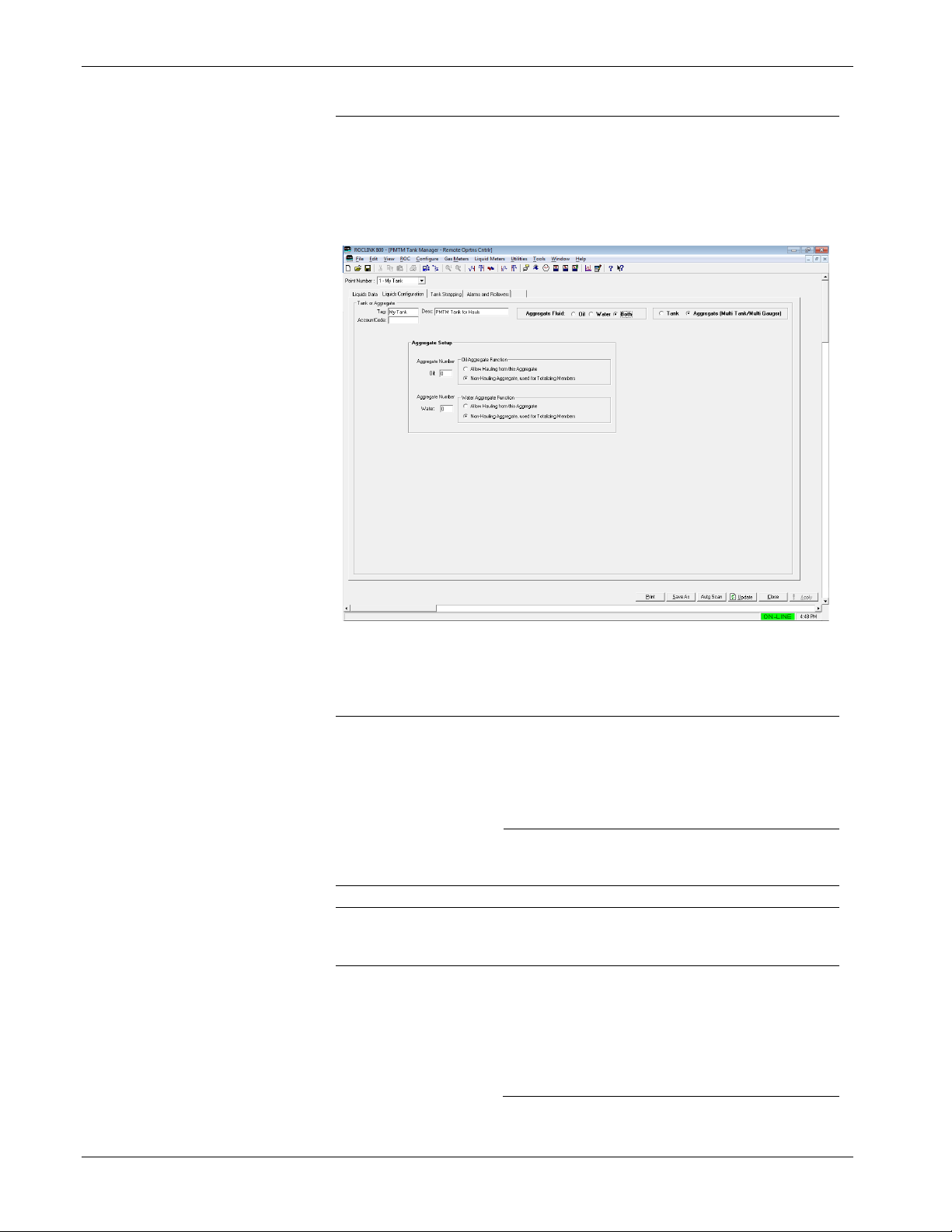
3.2.2 PMTM Tank Manager – Liquids Configuration Tab
Use this screen to configure tanks or aggregates.
To access this screen:
1. Select the Liquids Configuration tab on the Tank Manager screen.
The Liquids Configuration screen displays:
Page 47

Tank Manager User Manual (for ROC800-Series and FloBoss 107)
Revised June-2019 Configuration 43
Figure 3-8. Tank Manager Screen – Liquids Configuration tab, Oil
Page 48

Tank Manager User Manual (for ROC800-Series and FloBoss 107)
44 Configuration Revised June-2019
Figure 3-8a. Tank Manager Screen – Liquids Configuration tab, Water
2. Review the values in the following fields:
Field
Description
Tank or Aggregate
Tag
Provides a 10-character alphanumeric
identifier for the tank.
Account Code
Provides an accounting code (if applicable) to
identify this tank.
Desc
Provides a 20-character alphanumeric
identifier for the tank, which can be used if the
facility measurement point (FMP) identifier
exceeds the 10 characters allowed for the tag.
Page 49

Tank Manager User Manual (for ROC800-Series and FloBoss 107)
Revised June-2019 Configuration 45
Field
Description
Primary Fluid
Indicates the liquid to haul from this tank or
aggregate. Valid options are Oil or Water.
Note: The Hauling and Production Options
pane of this screen changes
depending on the Primary Fluid
option you choose. When you
choose the Aggregate (Multi
Tank/Multi Gauger) option, this
displays Aggregate Fluid and the
valid options become Oil, Water, or
Both.
Tank
You select this option if the object you define
represents a single liquid tank.
Aggregate (Multi
Tank/Multi Gauger)
You select this option if the object you define
represents a combination of multiple tanks.
Tank Setup
Note: This frame displays only if you select Tank from the Tank or
Aggragate frame.
Max Volume per
Tank
This read-only field specifies the maximum
capacity of the tank.
Load Line Elevation
Specifies the height from the bottom of the
tank where the loading flow line out of the
tank is located. This value is used when
determining the free water clearance for a
haul. During a haul, the free water clearance
is calculated by subtracting the oil/water
interface level from this value. If the free water
clearance is less than the required 4 inches
(or equivalent), a warning indication is
provided.
Aggregate
Membership
Specifies the aggregate to which this tank
belongs.
Page 50
Tank Manager User Manual (for ROC800-Series and FloBoss 107)
46 Configuration Revised June-2019
Field
Description
Aggregate Setup
Note: This frame displays only if you select Aggregate from the
Tank or Aggregate frame. An aggregate is the combination
of multiple tank instances. On the ROC800, if this tank
instance is to be used as an aggregate, the majority of the
tank configuration is hidden from the screen, and only the
aggregate setup frame is shown.
Aggregate Number:
Oil
Assigns an aggregate number. All tanks you
tag with this number roll up into this
aggregate.
Note: This field displays only if you select
Oil or Both as the Aggregate Fluid.
Aggregate Number:
Water
Assigns an aggregate number. All tanks you
tag with this number roll up into this
aggregate.
Note: This field displays only if you select
Water or Both as the Aggregate
Fluid.
Oil/Water Aggregate
Function
Specifies whether the aggregate is hauled
directly or if this aggregate totalizes the
production of the member tanks and hauls.
Tank Zone Instrumentation
Gauger Setup
Note: This frame displays only if you select Tank as the
configuration option.
Interfaced
Select to indicate that the tank has gauges for
both oil and water.
Note: Selecting this value removes the Qty
of Equalized Tanks w/Single Gauge
field from the Tank Setup pane (and
sets this value to 1) and displays the
Water Gauge field.
Page 51

Tank Manager User Manual (for ROC800-Series and FloBoss 107)
Revised June-2019 Configuration 47
Field
Description
Top Gauge
Click to display the Select TLP screen and
define a TLP to hold the Top gauge input
value.
Water Gauge
Click to display the Select TLP screen and
define a TLP to hold the water gauge input
value.
Note: This field displays only if you enable
the Interfaced option.
Samples used in
Filtering
Indicates the number of four-second scan
samplings the program uses for filtering. The
default is 10.
Gauge Units
Defines the gauge units. Click to display all
valid units.
Gauger Value Validity
Max Valid EUs
Specifies the maximum number of valid
engineering units the program uses when
validating gauger value.
Max Change
Indicates the maximum change, in volume per
minute, the program accepts when validating
gauger value.
Max 1-Scan Volume
Change
Indicates the maximum change in level the
program accepts during a single scan when
validating gauger value.
Scan-to-Scan Change: The program scans
the top level gauge every 4 seconds. This
setting specifies the maximum value (in units
of liquid volume) that the level gauge is
allowed to change without being considered
invalid. Should a level gauge transmitter
malfunction, this will keep the invalid reading
from being interpreted as true production.
Max Time Invalid (Reset): If the level gauge
malfunction, it provides an unrealistic reading.
This setting determines how long to wait
before re-baselining the understood true level
of the tank. After a guage validity error occurs,
if it is cleared before this configurable time
expires, the large sudden change in level from
the gauge will not be interpreted as true
production.
Oil Density
Selects the TLPs that determine the specific
gravity, temperatures, and pressure. The
program uses these values to calculate the oil
density. You can also manually enter specific
gravity, temperature, and pressure values in
the space provided.
Note: This section displays only when you
select Oil as the Primary Fluid.
Oil Temperature
Sets the TLP of the parameter the program
use to determine the oil temperature. You can
manually enter the temperature value in the
space provided
Note: This section displays only when you
select Oil as the Primary Fluid.
Page 52

Tank Manager User Manual (for ROC800-Series and FloBoss 107)
48 Configuration Revised June-2019
Field
Description
Oil Pressure
Sets the TLP of the parameter the program
use to determine the oil pressure. You can
manually enter the temperature value in the
space provided
Note: This section displays only when you
select Oil as the Primary Fluid.
S and W
Set the TLP of the parameter the program will
use to determine the amount of sediment and
water in the oil. If a live input is not defined,
you can manually enter a fixed S&W value for
the tank in the space provided.
Note: This section displays only when you
select Oil as the Primary Fluid.
Water Density
Sets the TLP of the parameter the program
use to determine the water specific gravity.
You can manually enter the temperature
value in the space provided
Note: This section displays only when you
select Water as the Primary Fluid.
Water Temperature
Sets the TLP of the parameter the program
use to determine the water. If a live input is
not defined, you can manually enter a fixed
water temperature for the tank in the space
provided
Note: This section displays only when you
select Water as the Primary Fluid.
Hauling and Production Options
Oil
Enable Production
Measurement via
Level
Enables configuration of production and
hauling options.
Infer Prod while
Hauling
Enables the program to calculate inferred
production during the haul and adjust hauled
volume accordingly. This situation occurs
when your setup injects the production into
the tank while the haul is currently in
progress.
Page 53

Tank Manager User Manual (for ROC800-Series and FloBoss 107)
Revised June-2019 Configuration 49
Field
Description
Stabilization
Parameters
This feature can be used to track the volume
changes in an oil tank which are attributed to
stabilization and settling of the product.
Drops in level which are not large enough to
trigger an auto haul can be measured and
tracked as stabilization loss. Click to select
from the list:
▪ Do Not Accumulate Loss due to
Stabilization – Small in level due to
stabilization are ignored.
▪ Accumulate Stabilization Loss – Drops in
level due to stabilization are recorded as
separate volume accumulators (as seen on
the Liquid Data tab).
▪ Accumulate Loss and Add To Production –
Drops in level due to stabilization are
recoded as separate volume accumulators
(as seen on the Liquid Data tab) and the
accumulation is also added to the Oil
Produced accumulators.
Stabilizer Timer
Indicates the amount
of time that must
pass, before a small
drop in level is
determined to be oil
stabilization, and the
volume quantity is
added to the
stabilization loss
accumulators. When
the timer is in use,
the Remaining field
will count down from
the Preset value, to
zero. Once it reaches
zero, it will
automatically reset to
the Preset time.
Auto Hauling Configuration
Auto Haul Using
Level
Enables the program
to auto-detect a haul
based on a drop in
level even without
input from the HMI to
automatically trigger
a haul.
Page 54

Tank Manager User Manual (for ROC800-Series and FloBoss 107)
50 Configuration Revised June-2019
Field
Description
Apply Density
Correction to Auto
Hauls
Enables corrections
of the volume of the
haul to to base
conditions (NSV),
when performing
auto-hauls. When
you enable this
option, you must
configure the
appropriate tank
instrumentation
(density,
temperature, S&W,
etc) or you must
enter manual values.
Record Water
Volume Hauled
When enabled and
an interfaced (oil and
water) gauge is used,
a drop in the water
level during an auto
haul for oil will result
in that water quantity
being recorded. This
is only true when the
interface level is
above the unsafe
zone for the tank, as
defined by the Load
Line Elevation.
Note: This field
displays only when
you enable Auto
Haul Using Level.
Record Oil
Volume Hauled
When enabled and
an interfaced (oil and
water) gauge is used,
a drop in the oil level
during an auto haul
for water will result in
that oil quantity being
recorded. This is
only true when the
interface level is
above the unsafe
zone for the tank, as
defined by the Load
Line Elevation.
Note: This field
displays only when
you enable Auto
Haul Using Level.
Page 55

Tank Manager User Manual (for ROC800-Series and FloBoss 107)
Revised June-2019 Configuration 51
Field
Description
Minimum Oil Haul
Indicates the
minimum amount of
oil level decrease that
automatically triggers
a haul. The default
value is 15.0.
Note: This field
displays only when
you enable Auto
Haul Using Level.
Maximum Oil Haul
Indicates the
maximum volume of
oil on a single haul
(ticket). Exceeding
this value triggers the
creation of additional
logs. The default
value is 200.0.
Note: This field
displays only when
you enable Auto
Haul Using Level.
Close-Out Auto-
Detect Haul after [ ]
Minutes of No-Flow
Sets the amount of
no-flow time, in
minutes, to
automatically trigger a
close-out. The default
value is 15.0.
Note: This field
displays only when
you enable Auto
Haul Using Level.
Water
Enable Production
Measurement via
Level
Enables configuration of production and
hauling options.
Infer Prod while
Hauling
Enables the program to calculate inferred
production during the haul and adjust hauled
volume accordingly. This situation occurs
when your setup injects the production into
the tank while the haul is currently in progress.
Auto Hauling
Configuration
Auto Haul Using
Level
Enables the program
to auto-detect a haul
based on a drop in
level even without
input from the HMI to
automatically trigger a
haul.
Page 56

Tank Manager User Manual (for ROC800-Series and FloBoss 107)
52 Configuration Revised June-2019
Field
Description
Minimum Water
Haul
Indicates the
minimum amount of
water level decrease
that automatically
triggers a haul. The
default value is 15.0.
Note: This field
displays only when
you enable Auto
Haul Using Level.
Maximum Water
Haul
Indicates the
maximum volume of
water on a single
haul (ticket).
Exceeding this value
triggers the creation
of additional logs.
The default value is
180.0.
Note: This field
displays only when
you enable Auto
Haul Using Level.
Close-Out Auto-
Detect Haul after [ ]
Minutes of No-Flow
Sets the amount of
no-flow time, in
minutes, to
automatically trigger
a close-out. The
default value is 15.0.
Note: This field
displays only when
you enable Auto
Haul Using Level.
3. Click Apply to save any changes you have made to this screen.
4. Proceed to Section 3.2.3 to configure the Tank Strapping tab.
3.2.3 PMTM Tank Manager – Tank Strapping Tab
Use this screen to configure the calibration to allow for the conversion
of a level (in feet or inches or meters, etc) to an equivalent volume of
product in the tank.
Note: This tab does not display anything when you select Aggregate
(Multi Tank/Multi Gauger) from the Tank or Aggrate frame.
To access this screen:
1. Select the Tank Strapping tab on the Tank Manager screen. The
Tank Strapping screen displays:
Page 57

Tank Manager User Manual (for ROC800-Series and FloBoss 107)
Revised June-2019 Configuration 53
Figure 3-9. Tank Manager Screen – Tank Strapping tab
2. Review the values in the following fields:
Field
Description
Strapping Table
for Tank #
Displays the unique tank description (tag) you
enter on the previous screen.
Ambient
Temperature
Sets the TLP of the parameter the program
use to determine the ambient temperature of
the site. If a live input is not defined, you can
manually enter a fixed ambient temperature in
the space provided. Click to define a TLP
for the ambient temperature.
Lease Tank ID
Sets a numeric identifier for the tank within the
lease. This optional field is provided for
informational purposes only.
Effective Date
Sets the date of the last calibration of the tank
in the form of YYYYMMDD, where YYYY is
the 4 digit year, MM is the 2 digit month, and
DD is the 2 digit day. For example, 20151201
would be December 1st, 2015. This optional
field is provided for informational purposes
only.
Page 58

Tank Manager User Manual (for ROC800-Series and FloBoss 107)
54 Configuration Revised June-2019
Field
Description
Tank Shell
Material
Selects material of construction of your tank.
The program uses this selection to calculate
the CTS value of the tank. Click to display
all valid material types.
Tank Shell Ref
Temp:
Sets the reference temperature of the tank
during calibration. The program uses this
temperature value to calculate the CTS value
of the tank. This value is typically 60 deg F or
15 deg C.
Tank Insulated?
Indicates whether the tank includes insulation.
The program uses this selection to calculate
the CTS value of the tank.
Incremental
Height:
Selects the units of the smallest linear
increment for the strapping table. Click to
display all valid incremental height options.
Volume Unit per
Increment:
Selects the volume units of the strapping
value increments. Click to display all valid
volume unit options.
Current Strap In
Use
Shows the calculated strapping value in-use
for the current level of the tank.
Table Entry Control
Note: These options determine which values the program requires
to enter and which values the program automatically
calculates for the strapping table.
Level
Determines the primary data entry type for the
strapping table. Click to display all valid
level entry options. If the strapping table data
includes tank height levels, select Enter
Gauge Values. If the strapping table data
available includes volume increments per
zone, select Enter Increments.
Increments
Sets if each zone uses the number of the
volume increments or the number of the end
increment in the zone. Click to display all
increment entry options.
Note: This field only displays when you
select Enter Increments from the
Level field.
Volume
Sets the volume zone to either volume per
increment or the volume of the entire zone.
Click to display all valid volume entry
options.
Zones in Table
Select the number of zones included in the
strapping table information available.
Note: If using a single numerical strapping
value for the tank (rather then a
table), set this option to a value of 1.
Zones In Use
Displays the number of zones that are
currently valid and in use by the strapping
table routine. If configuration has been
performed correctly, this should equal the
value selected for the Zones In Table field.
Zone #
Indicates the zone number of the tank
strapping entry.
Page 59

Tank Manager User Manual (for ROC800-Series and FloBoss 107)
Revised June-2019 Configuration 55
Field
Description
Feet
Meters
Sets the largest linear unit value for the
strapping data based on tank height gaude.
Continue to the next column if the height
gauge levels include additional resolution
(such as inches).
The label for this column changes, depending
on the Incremental Height option you select.
This section is in Feet if you select inch, 1/4-
inch, 1/8-inch, 1/16-inch, or 0.01-foot as
Increment Height. This section is in Meters if
you select centimeter or millimeter as the
Increment Height.
Inches
Centimeter
Sets the short linear unit value for the
strapping data based on tank height gauge
values. Continue to the next column if the
height gauge levels include additional
resolution (such as ¼-inch). You enter a 0
value if the height gauge values include no
additional resolution.
The label for this column changes, depending
on the Incremental Height option you select.
This section is in Inch if you select inch, 1/4-
inch, 1/8-inch, 1/16-inch, or 0.01-foot as
Increment Height. This section is in
Centimeters if you select centimeter or
millimeter as the Increment Height.
N/A
1/4 Inches
1/6 Inches
1/8 Inches
Sets the fraction of the short linear unit value
for the strapping data. Enter a value of 0 if the
height gauge values include no additional
resolution (column Label shows “N/A”).
The label for this column changes, depending
on the Incremental Height option you select.
The section label is N/A if you select inch,
0.01-foot, Centimeter, or Millimeter as
Increment Height. The section label is ¼inch if you select ¼-inch as the Increment
Height, 1/8-inch if you select 1/8-inch as the
Increment Height, or 1/16-inch if you select
1/16-inch as the Increment Height.
# Increments
Sets the number of volume increments in the
zone. This field becomes writable when you
select Enter # of Increments from the
Increments field.
End Increment #
Sets the end increment number. This field
becomes writable when you select Enter End
Increments # from the Increments field.
I-Factor
For each zone in the table, the tank height
levels must include a corresponding volume;
you enter the tank volume quantity per
increment in this field. Note that the Accum
Volume in the next column is this value
multiplied by the number of increments in the
zone.
Page 60

Tank Manager User Manual (for ROC800-Series and FloBoss 107)
56 Configuration Revised June-2019
Field
Description
Accum Volume
If the tank volume per zone is determined by a
single accumulated volume value, enter that
accumulated volume here. Note that the I-
Factor in the previous column is this value,
divided by the number of increments in the
zone.
3. Click Apply to save any changes you have made to this screen.
4. Proceed to Section 3.2.4 to configure Alarms and Rollovers.
3.2.4 PMTM Tank Manager – Alarms and Rollovers Tab
This screen displays real-time totals for a variety of accumulating values
for the current haul.
To access this screen:
1. Select the Alarm and Rollovers tab on the Tank Manager screen.
The Alarm and Rollover screen displays:
Figure 3-10. Tank Manager Screen – Alarms and Rollovers tab, Oil
Page 61

Tank Manager User Manual (for ROC800-Series and FloBoss 107)
Revised June-2019 Configuration 57
Figure 3-10a. Tank Manager Screen – Alarms and Rollovers tab, Water
2. Review the contents of this screen.
Field
Description
Level Alarms
Alarms Enable
Enables the logging of alarms based on the
tank level.
Tank High
Level:
Sets the tank level alarm high value. If the
tank level exceeds this value, a tank high level
alarm alerts and creates an entry in the alarm
log of the FB107 or the ROC800.
Hours until HI
Level:
This read-only field displays the rate at which
the tank level is increasing. This field will
show an estimate for the number of hours
until the configured Tank high level is
reached.
Tank Low
Level:
Sets the tank level alarm low value. If the tank
level goes below this value, a tank low level
alarm alerts and creates an entry in the alarm
log of the FB107 or the ROC800.
Page 62

Tank Manager User Manual (for ROC800-Series and FloBoss 107)
58 Configuration Revised June-2019
Field
Description
Tank Level
Deadband:
Provides a deadband, to avoid repetitive
setting and clearing of alarms. When the inuse level value crosses the high or low level
threshold and creates an alarm, the level
value must change back within the required
threshold plus this deadband value, for the
alarm to clear.
Water High Level
Sets the value for the tank high water level at
which an alarm will be raised in a primarily oil
tank.
Note: This field is displays only when you
select Oil as the Primary Fluid for the
tank, and an interfaced (oil and water)
tank gauge is defined. Refer to Figure
3.10 for details.
Oil High Level
Sets the value for the tank high oil level at
which an alarm will be raised in a primarily
water tank.
Note: This field is displayed only when you
select Water as the Primary Fluid for
the tank, and an interfaced (oil and
water) tank gauge is defined. Refer to
Figure 3.10a for more details.
Contract Hour Configuration
Contract Hour
Sets the hour of the day when the Today
values rollover and become the Yesterday
values. The valid values include 0 through 23.
Log Hauls that
Occur During
Contract Hour to:
Selects which day should the Totals from the
haul belongs. This is applicable to situations
when the haul begins before a contract hour
and ends during the contact hour.
Non-Hauling Tank Outlet Meters
Some applications require the transfer of fluids out of a tank, but
not through the normal hauling mechanism. Assuming you use a
meter for this activity and the meter provides a signal to the
ROC800 or FB07 where you install the tank manager, this feature
provides a way to measure these outbound fluids.
Oil Meter
Accumulator
Def:
Click to display the Select TLP screen and
define a TLP to hold the oil meter input to the
device. This is TLP is typically an incremental
accumulator value, such as a pulse input
running total.
Enable:
Enables the Oil Meter Definition option.
Water Meter
Accumulator
Def:
Click to display the Select TLP screen and
define a TLP to hold the water meter input to
the device. This is TLP is typically an
incremental accumulator value, such as a
pulse input running total.
Enable:
Enables the Water Meter Definition option.
Page 63

Tank Manager User Manual (for ROC800-Series and FloBoss 107)
Revised June-2019 Configuration 59
Field
Description
Tank Flags
Selects a tank flag to take effect.
Normal: Idle state (no action in progress).
Force End of Day: Causes a new day event
to occur immediately. All Today accumulators
rollover into the yesterday accumulators.
Force End of Month: Causes a new month
event to occur immediately. All This Month
accumulators rollover into the Previous Month
accumulators.
Cold Start Tank: Clears out all accumulators
(Daily, Monthly, and Accumulated) for the
tank.
3. Proceed to Section 3.3 to configure the PMTM Allocated Well
Values screen.
3.3 PMTM Allocated Well Values
Use this screen and its tabs to view and configure well allocation and
production details.
To access this screen:
1. From the Directory Tree, double-click User Program.
2. Double-click one of the following:
▪ For the ROC800: Program #1, PMTM_v409_00_8t4w.
▪ For the FB107: PM Tank Manager.
3. Double-click one of the following:
▪ For the ROC800: Display #197, PMTM Allocated Well
Values.
▪ For the FB107: Display #81, PMTM Allocated Well Values
4. Double-click #1, Well 1 for either the ROC800 or FB107.
5. The Allocated Well Values screen displays, showing the
Allocation/Production Values tab.
Page 64

Tank Manager User Manual (for ROC800-Series and FloBoss 107)
60 Configuration Revised June-2019
Figure 3-11. Allocated Well Values Screen
3.3.1 PMTM Allocated Well Values – Allocation/Production Values Tab
This screen (which displays first when you open the Allocated Well
Values screen) provides an at-a-glance summary of the oil and water
allocation values currently defined for the selected well.
Page 65

Tank Manager User Manual (for ROC800-Series and FloBoss 107)
Revised June-2019 Configuration 61
Figure 3-12. Allocated Well Values Screen – Allocation/Production Values tab
1. Review the values in the following fields.
Field
Description
Point Number
Identifies the well for these allocation values.
Well ID
This read-only field shows the identifying
label associated with this well.
Well Description
Provides a 20-character alphanumeric
identifier for the well which can be used to
further describe it, or can be used if the facility
measurement point (FMP) identifier exceeds
the 10 characters allowed for the tag.
Page 66

Tank Manager User Manual (for ROC800-Series and FloBoss 107)
62 Configuration Revised June-2019
Field
Description
Oil Allocation
Values from
Assigned
Tankage
Indicates, in average barrels, the daily
production of oil for the selected well. You can
edit this field, if necessary.
Alloc Pct
Shows the percent of total production into a
tank the well produces. For example, you
have two wells producing into the same tank,
this shows the percentage on how much of
that tanks production was from each individual
well. If well 1 is producing 3 times the
production of well 2, the well 1 would have
75% Alloc Pct and well 2 would have 25%
Alloc Pct.
Note: This field displays only when you
select Use Liquid Production Meters
as the Allocation Well Liquid
Production Method from the
Allocation/Production Configuration
tab.
into
Displays the tag of the tank the well is
producing (oil or water) into.
Instance #
Displays the instance number of the tank the
well is producing (oil or water) into.
Produced
This read-only field displays the current day,
previous day, the current month, the previous
month, and the total accumulated production
volume for the oil tank.
Hauled
This read-only field displays the current day,
previous day, the current month, the previous
month, and the total accumulated hauling
volume for the oil tank.
Daily Prod
Average
Display the daily production average for the
current and previous month. You can also
update the daily production average for the
current month.
Water Allocation
Values from
Assigned
Tankage
Indicates, in average barrels, the daily
production of water for the selected well. You
can edit this field, if necessary.
Alloc Pct:
Shows the percent of total production into a
tank the well produces. For example, you
have two wells producing into the same tank,
this shows the percentage on how much of
that tanks production was from each individual
well. If well 1 is producing 3 times the
production of well 2, the well 1 would have
75% Alloc Pct and well 2 would have 25%
Alloc Pct.
Note: This field displays only when you select
Use Liquid Production Meters as the
Allocation Well Liquid Production
Method from the
Allocation/Production Configuration
tab.
Page 67

Tank Manager User Manual (for ROC800-Series and FloBoss 107)
Revised June-2019 Configuration 63
Field
Description
Into
Displays the tag of the tank the well is
producing (oil or water) into.
Instance #
Displays the instance number of the tank the
well is producing (oil or water) into.
Produced
This read-only field displays the current day,
previous day, the current month, the previous
month, and the total accumulated production
volume for the water tank.
Hauled
This read-only field displays the current day,
previous day, the current month, the previous
month, and the total accumulated hauling
volume for the water tank.
Disposal
This read-only field displays the current day,
previous day, the current month, the previous
month, and the total accumulated disposal
volume for the water tank.
Daily Prod
Average
Display the daily production average for the
current and previous month. You can also
update the daily production average for the
current month.
Separator Oil Production Values
Note: This section displays only when you select Use Liquid
Production Meters as Allocate Well Liquid Production
Method from the Allocation/Production Configuration
tab.
Produced
This read-only field displays the current day,
previous day, the current month, the previous
month, and the total accumulated production
volume of oil from the separator.
Seconds of
Meter
Overrange
Counts the number of seconds the (oil or
water) meter flow rate exceeds the maximum
flowrate.
Separator Water Production Values
Note: This section displays only when you select Use Liquid
Production Meters as Allocate Well Liquid Production
Method from the Allocation/Production Configuration
tab.
Produced
This read-only field displays the current day,
previous day, the current month, the previous
month, and the total accumulated production
volume of water from the separator.
Seconds of
Meter
Overrange
Meter 1
Counts the number of seconds the (oil or
water) meter flow rate exceeds the maximum
flowrate for meter 1.
Seconds of
Meter
Overrange
Meter 2
Counts the number of seconds the (oil or
water) meter flow rate exceeds the maximum
flowrate for meter 2.
Monthly GLR
This Month
Specifies the GLR value of the current month.
You can edit this field, if necessary.
Prev Month
This read-only field displays the GLR value of
the previous month.
Page 68

Tank Manager User Manual (for ROC800-Series and FloBoss 107)
64 Configuration Revised June-2019
Field
Description
Initiate 3 Day
GLRs
Enables the system to recalculate GLR values
based on the manually entered 3-day
accumulated value.
2. Proceed to Section 3.3.2 to configure the Allocation/Production
Config tab.
3.3.2 PMTM Allocated Well Values – Allocation/Production Config Tab
Use this screen to indicate how the program should allocate production
totals back to associated wells.
To access this screen:
1. Select the Allocation/Production Configuration tab. The
Allocation/Production Configuration screen displays:
Figure 3-13. Allocated Well Values Screen – Allocation/Production Configuration tab
2. Review the values in the following fields:
Field
Description
Well ID
Specifies the tag identifier for this well. You
can define allocations for up to 12 wells.
Page 69

Tank Manager User Manual (for ROC800-Series and FloBoss 107)
Revised June-2019 Configuration 65
Field
Description
Well Description
(for ROC800)
Provides a 20-character alphanumeric
identifier for the well which can be used to
further describe it, or can be used if the facility
measurement point (FMP) identifier exceeds
the 10 characters allowed for the tag.
Contract Hour
Specifies the contract hour for this well.
Accumulators roll over at the contract hour
you define here.
Allocate Well
Liquid
Production
Method
Indicates the allocation method the program
uses.
Tank Fluid Prod Vol x Ratio: No Gas
Weight: Multiplies the fluids produced into the
tanks by the Well Allocation Percentage to
determine the allocated volume for this well.
Tank Fluid Prod x Ratio: Gas Vol
Weighted: Multiples the fluids produced into
the tanks by the Well Allocation Percentage
(adjusted by the percentage of total gas
volume produced by this well) to determine
the allocation volume for this well. This is the
default selection.
Note: Selecting this option displays the Gas
Meter Used for GLR Ratios pane.
By Gas Volume / Manual Gas/Fluid Ratio:
Allocates fluids based on fixed GLR factors by
dividing the gas volume by the manual gas-tofluid ratios. This method decouples well
allocation volumes from the total volume
produced into the tanks.
Note: Selecting this option displays the Gas
Meter Used for GLR Ratio and the
Manual Gas/Fluid Ratios panes and
removes the Tank or Aggregate
Produced Info pane.
Use Liquid Production Meters: Allocates the
production of the well based on input from
liquid production meters. Allocation
percentages can be automatically derived and
updated with this method.
Note: Selecting this option displays the
Liquid Production Meters pane.
Tank or Aggregate Produced Into
Identifies the tank or aggregate into which the well produces and
indicates the percentage of fluids allocated to this well.
This pane displays only when you select either Tank Fluid Prod
Vol*Ratio: No Gas Weighted, Tank Fluid Prod Vol*Ratio: Gas
Vol Weighted or Use Liquid Production Meters as Allocate Well
Liquid Production Method.
Available Tank or
Aggregate
Defines the specific tank or aggregate for the
respective fluid. Click to display all defined
tanks or aggregates.
Well Allocation
Percentages
Indicates the percentage of total volume
produced into the selected tank/aggregate
allocated to this well.
Page 70

Tank Manager User Manual (for ROC800-Series and FloBoss 107)
66 Configuration Revised June-2019
Field
Description
Auto-Update w/
Calculated %
Note: These two checkboxes displays only
when you select Use Liquid
Production Meters as Allocate Well
Liquid Production Method.
Flags
Forces the program to clear process
accumulators or GLR values and perform on-
demand rollovers of daily and months
accumulators.
Gas Meter Used
for GLR Ratios
Displays the Select TLP screen you use to
define a TLP to accumulate gas meter values.
The program selects the correct AGA
parameter from the associated logical
number.
Note: This pane displays only when you
select either Tank Fluid Prod
Vol*Ratio: Gas Vol Weighted or By
Gas Volume / Manual Gas/Fluid
Ratio as Allocate Well Liquid
Production Method.
Manual Gas
/Fluid Ratios
Indicates a manual value for the gas-to-liquid
ratio for oil, water, and total fluid.
Note: This pane displays only when you
select By Gas Volume / Manual
Gas/Fluid Ratio as Allocate Well
Liquid Production Method.
Liquid
Production
Meters
Indicates the specific oil or water meters to be
used in allocation.
Note: This pane displays only when you
select Use Liquid Production
Meters as Allocate Well Liquid
Production Method.
Enable Oil
Meter
Select to enable the program to use the oil
meter.
Rate Pf Def
Displays the Select TLP screen you use to
define a TLP to store the defined rate point.
Max Valid
Rate/Min
Defines the maximum allowable flow rate per
minute. While this value is exceeded, the
program does not accumulate liquid volume
for this meter and records the amount of time
in seconds.
Note: This assumes that gas (rather than
fluid) is flowing through this meter
during this excursion.
Page 71

Tank Manager User Manual (for ROC800-Series and FloBoss 107)
Revised June-2019 Configuration 67
Field
Description
OR
An additional user defined logic expression
can be configured, to determine when the
flowrate signal provided by a liquid meter is
invalid. When the result of this logic is “true”,
the meter flow is considered invalid, and it is
not recorded. This can be used to detect a
dump valve which is stuck open, or an alarm
condition from a smart meter such as a
Coriolis. Click to select a live process
variable to be monitored. Click to select an
operator, such as greater than (>), less than
(<), equal to (==), etc. Finally configure the
value at which the process variable is
considered invalid or in alarm.
Enable Water
Meter
Select to enable the program to use the
primary water meter.
Rate Pf Def
Displays the Select TLP screen you use to
define a TLP to store the defined rate point for
the primary water meter.
Max Valid
Rate/Min
Defines the maximum allowable flow rate per
minute. While this value is exceeded, the
program does not accumulate liquid volume
for this meter and records the amount of time
in seconds.
Note: This assumes that gas (rather than
fluid) is flowing through this meter
during this excursion.
OR
An additional user defined logic expression
can be configured, to determine when the
flowrate signal provided by a liquid meter is
invalid. When the result of this logic is “true”,
the meter flow is considered invalid, and it is
not recorded. This can be used to detect a
dump valve which is stuck open, or an alarm
condition from a smart meter such as a
Coriolis. Click to select a live process
variable to be monitored. Click to select an
operator, such as greater than (>), less than
(<), equal to (==), etc. Finally configure the
value at which the process variable is
considered invalid or in alarm.
Enable Second
Water Meter
Select to enable the program to use a
secondary water meter.
Rate Pf Def
Displays the Select TLP screen you use to
define a TLP to store the defined rate point for
the secondary water meter.
Max Valid Rate
BPM
Defines the maximum allowable flow rate per
minute. While this value is exceeded, the
program does not accumulate liquid volume
for this meter and records the amount of time
in seconds.
Note: This assumes that gas (rather than
fluid) is flowing through this meter
during this excursion.
Page 72

Tank Manager User Manual (for ROC800-Series and FloBoss 107)
68 Configuration Revised June-2019
Field
Description
OR
An additional user defined logic expression
can be configured, to determine when the
flowrate signal provided by a liquid meter is
invalid. When the result of this logic is “true”,
the meter flow is considered invalid, and it is
not recorded. This can be used to detect a
dump valve which is stuck open, or an alarm
condition from a smart meter such as a
Coriolis. Click to select a live process
variable to be monitored. Click to select an
operator, such as greater than (>), less than
(<), equal to (==), etc. Finally configure the
value at which the process variable is
considered invalid or in alarm.
PMSC Action
Block Optional
PSD/TSD Trip
Point
Indicates the specific trip point defined in the
Surface Control Manager application for either
permanent shut down (PSD) or temporary
shut down (TSD).
For further information on configuring these
values, refer to the Surface Control Manager
User Manual (for ROC800-Series and
FloBoss 107 Controllers), part D301759X012.
3. Proceed to Section 3.4 to configure the data base for the Haul Log
Viewer.
3.4 PMTM Haul Log Viewer
To access this screen:
1. From the Directory Tree, double-click User Program.
2. Double-click one of the following:
▪ For the ROC800: Program #1, PMTM _v409_00_8t4w.
▪ For the FB107: PM Tank Manager.
3. Do one of the following:
▪ For the ROC800: Double-click Display #198, PMTM Haul Log
Viewer.
▪ For the FB107: Go to User Display and double-click Display #1
– PMTM Haul Log Viewer.
Note: You may have a different display number. Use the
display number that you loaded this screen.
Page 73

Tank Manager User Manual (for ROC800-Series and FloBoss 107)
Revised June-2019 Configuration 69
3.4.1 PMTM Haul Log Viewer – Haul Log Overview Tab
Figure 3-14. Haul Log Overview Screen
The Haul Log Overview screen, as shown in Figure 3-14, displays the
last 20 hauls, with the most current haul at the top of the screen. Each of
the values in this log is stored in an individual TLP. The most recent
haul is logical 1 and the last haul is logical 20. A SCADA system can
access these logs by polling for TLPs and logical addresses that
correspond to the entry in the sequence. The program assigns every
completed haul a transaction number. By polling the Transaction
Number TLP [198,1,31], the SCADA system can determine when a new
log is available.
3.4.2 PMTM Haul Log Viewer – Detailed Viewer and SCADA Pickup Tab
To retrieve detailed haul information:
1. Enter the transaction number of the desired haul into the
Retrieve this Haul Transaction Number field.
2. Click Apply and review all information about that haul.
Page 74

Tank Manager User Manual (for ROC800-Series and FloBoss 107)
70 Configuration Revised June-2019
Figure 3-15. Detailed Viewer and SCADA Pickup Screen
In addition to the 20 most recent hauls, which are stored in TLPs for
easy access, more haul log records are stored within the device, on the
flash file system. The ROC800 stores the most recent 512 hauls in this
manner, and the FB107 stores the most recent 64. These additional haul
records can be retrieved one at a time by a SCADA system. This is
accomplished by writing the haul transaction number to be retrieved
into the field mentioned above (which is TLP [198,0,44] on the
ROC800, and TLP [180,0,44] on the FB107). The requested record will
be populated into logical instance 0 of the Tank Manager haul logs point
type (which is PT 198 on the ROC800, and PT 180 on the FB107).
For more details, refer to Appendix B – Retrieving the Haul Logs via
SCADA.
Caution
The FB107 utilizes the flash file system of the FB107 to store the
previous 64 haul logs. When you perform the cold start of the device,
the flash memory space where these log records are located is restored
to the point of the previous save-to-flash event. Therefore, in order to
avoid the loss of data, and maintain synchronization with any SCADA
system, it is required to perform a save-to-flash BEFORE any sort of
cold start on the FB107.
Page 75

Tank Manager User Manual (for ROC800-Series and FloBoss 107)
Revised June-2019 Configuration 71
3.5 PMTM Load Out
Use this screen and its component tabs to configure haul details, view
specific haul values, and run system diagnostics.
To access this screen:
1. From the Directory Tree, double-click User Program.
2. Double-click one of the following:
1. For the ROC800: Program #1, PMTM _v409_00_8t4w.
2. For the FB107: PM Tank Manager.
3. Double-click one of the following:
▪ For the ROC800: Display #231, PMTM LoadOut.
▪ For the FB107: Display #83, PMTM LoadOut.
4. Double-click #1, LoadTerm 1 for either the ROC800 or FB107.
5. The Load Out screen displays, showing the Load Out Control tab:
Figure 3-16. Load Out Screen
Page 76

Tank Manager User Manual (for ROC800-Series and FloBoss 107)
72 Configuration Revised June-2019
Note: The light red highlighted border on this screen indicates that no
haul is currently underway. When a haul begins, this border
changes to green.
6. Review the values in the following fields:
Field
Description
Point Number
Identifies the loading terminal. Click to
display all defined loading terminals.
Note: This field appears on all Load Out tabs.
Haul Item Tag
Identifies the name of the HMI terminal as
defined on the HMI Instance Tag.
Note: This field appears on all Load Out tabs.
Ambient Temp
Indicates the ambient temperature.
7. Proceed to Section 3.5.1 the Load Out Operate tab.
3.5.1 PMTM Load Out – Load Out Operate Tab
Use this screen to perform a haul from a Tank Manager load out
terminal. Typically, a haul is performed via a local operator HMI panel,
however the ROCLINK 800 interface provided on this screen can be
used as well. This tab displays when you initially access this screen.
Figure 3-17. Load Out Screen – Load Out Operate tab
Page 77

Tank Manager User Manual (for ROC800-Series and FloBoss 107)
Revised June-2019 Configuration 73
1. Review the values in the following fields.
Field
Description
Load Out
Defines a tag name (up to 10 characters long)
for this hauling terminal. This value displays
on the HMI for driver selection.
There is also a 20-character alphanumeric
identifier for the load out terminal provided,
which can be used to further describe it, or
can be used if the facility measurement point
(FMP) identifier exceeds the 10 characters
allowed for the tag.
Notes:
▪ While a haul is in progress, this screen
displays messages to alert. Examples of
messages:
o Illegal Ticket Number
o Seal On Required
o ¼-Way Estimated Vol Xferred
▪ Multiple items on this screen will include a
colored asterisk next to the field. These
colored asterisks represent the states of
Manual Entry Required and Entry is
Validated. When a manual entry is
required the asterisk will be red until you
enter a value into the field. Once you enter
a value, the asterisk will change to green
and that field will be validated. Required
user interaction is defined on the Hauling
Screens Configuration tab.
Driver Login
Provides driver validation and ticketing information.
Company Code
Defines the numerical credentials of the
company. When the driver enters a company
code on the HMI, the program verifies and
validates the code against the ROC Hauler
Database (see Section 3.3) and shows the
validated company name in the Company
Verified field.
Note: This field requires manual entry.
Driver PIN
Defines the numerical credentials of the
driver. When the driver enters a driver code
on the HMI, the program verifies and validates
the code against the Hauler Companies
Database (see Section 3.3).
Note: This field requires manual entry.
Ticket Number
Provides the ticket number. This optional 20-
character field may be contractually required
by an agreement with the owner. The program
records this information in the haul log.
Note: This field may require manual entry
based on the settings selected on the
Hauling Screens Configuration tab.
Page 78

Tank Manager User Manual (for ROC800-Series and FloBoss 107)
74 Configuration Revised June-2019
Field
Description
Truck Number
Provides the truck number. This optional 10character field may be contractually required
by an agreement with the owner. The program
records this information in the haul log.
Note: This field may require manual entry
based on the settings selected on the
Hauling Screens Configuration tab.
Opening Edits
Allows the operator to enter information known at the start of a haul,
typically before the haul begins.
Object# to Haul
Provides the numerical equivalent of the
object to haul. If you define only one tank on
the Measurement Configuration tab, the
program automatically completes this field
when the driver has entered and validated the
company code and driver PIN. If you define
two or more tanks, the driver must enter the
tank they are hauling from.
Note: When hauling oil, the object number
to haul is the number of the tank
instance. If the driver wants to haul oil
from Tank 3, they would enter 3 in this
field. When hauling water, 100 is
added to the number of the tank
instance. If the driver wants to haul
water from Tank 3, they would enter
103 in this field.
Objects
Assigned
This field is read only shows the total number
of tanks or aggregates assigned to this load
out terminal. This is as determined by the
Assigned Tanks field on the Measurement
configuration tab.
Seal Off #
Provides the seal off number. This optional
field may be contractually required by an
agreement with the owner. The program
records this information in the haul log.
Note: This field may require manual entry
based on the settings selected on the
Hauling Screens Configuration tab.
Free Water
Clearance
This read-only field displays the amount of
level that water is from the tank outlet loading
line. For an oil haul, if the water level is too
close to the loading line (for example 4 inches
or less), this field provides a red warning
indication.
Haul Open Level
Specifies the level of the tank, expressed as
feet, inches, and quarters, at the beginning of
the haul.
Note: This field may require manual entry
based on the settings selected on the
Hauling Screens Configuration tab.
Page 79

Tank Manager User Manual (for ROC800-Series and FloBoss 107)
Revised June-2019 Configuration 75
Field
Description
Purchaser Code
Click to display all defined purchaser code.
Purchaser codes are an enumerated list of
strings that can be shown to an operator. For
more information on configuring the contents
of this list, see Section 3.7 PMTM Enumerated
Lists.
Disposition Type
Click to display all defined disposition type.
Disposition types are an enumerated list of
strings that can be shown to an operator. For
more information on configuring the contents
of this list, see Section 3.7 PMTM Enumerated
Lists.
Destination Code
Click to display all defined destination code.
Destination Codes are an enumerated list of
strings that can be shown to an operator. For
more information on configuring the contents
of this list, see Section 3.7 PMTM Enumerated
Lists.
Fluid Characteristics
The program records the fluid properties (temperature, pressure,
density, etc) of the product, in order to calculate the volume of a
haul. These values can come from live instrumentation configured
and assigned to the tank, from live instrumentation configured and
assigned to the load out terminal, or from values manually entered
by the operator. Depending on the measurement method selected
on the Measurement Configuration tab, and the Fluid
Characteristics section of the Hauling Screens Configuration tab,
the fields shown on the screen in this section will vary.
Temp Open
The temperature of the tank or fluid at the
opening of the haul.
Note: The description of this field changes
based on the user selection on the
global Units Configuration. The
default unit is DegF.
Temp Close
The temperature of the tank or fluid at the
closing of the haul.
Note: The description of this field changes
based on the user selection on the
global Units Configuration. The
default unit is DegF.
Pressure Open
The pressure of the tank or fluid at the
opening of a haul.
Note: The description of this field changes
based on the user selection on the
global Units Configuration. The
default unit is Psi.
Pressure Close
The pressure of the tank or fluid at the closing
of a haul.
Note: The description of this field changes
based on the user selection on the
global Units Configuration. The
default unit is Psi.
S and W% Open
The sediment and water percentage of the
tank or fluid at the opening of a haul.
Page 80

Tank Manager User Manual (for ROC800-Series and FloBoss 107)
76 Configuration Revised June-2019
Field
Description
Density
Density Open
The density of the tank or fluid at the opening
of a haul.
Note: The description of this field changes
based on the user selection on the
global Units Configuration. The
default unit is API Gr.
Density Close
The density of the tank or fluid at the closing
of a haul.
Note: The description of this field changes
based on the user selection on the
global Units Configuration. The
default unit is API Gr.
Density
Temperature
Open
The density temperature of the tank or fluid at
the opening of a haul.
Note: The description of this field changes
based on the user selection on the
global Units Configuration. The
default unit is DegF.
Density
Temperature
Close
The density temperature of the tank or fluid at
the closing of a haul.
Note: The description of this field changes
based on the user selection on the
global Units Configuration. The
default unit is DegF.
Driver Entered Fluid Prop For Manual ReCalc
These fields allow an operator to enter manual readings for the
S&W percent, temperature, and density, which may differ from the
values automatically recorded during the haul by live
instrumentation. These can be used later for a manual
recalculation of the haul totals.
S&W Pct
Indicates the operator entered value for the
sediment and water percentage.
Temp
Indicates the operator entered value for the
fluid temperature.
Note: This field displays only when the
Driver Entered Secondary
Calculation Parameter option is set to
Derive GSV from Manual Values on
the Hauling Screens Configuration tab.
Obs Density
Indicates the operator entered value for the
fluid observed density.
Note: This field displays only when the
Driver Entered Secondary
Calculation Parameter option is set to
Derive GSV from Manual Values on
the Hauling Screens Configuration tab.
Page 81

Tank Manager User Manual (for ROC800-Series and FloBoss 107)
Revised June-2019 Configuration 77
Field
Description
Closing Edits
Allows the operator to enter any additional information (which may
be required or optional) at the end of a haul.
Seal On #
Provides the seal on number. This optional
field may be contractually required by an
agreement with the owner. The program
records this information in the haul log.
Note: This field may require manual entry
based on the settings selected on the
Hauling Screens Configuration tab.
Driver Haul Open
Level
Allows the operator to enter a measured value
for the level of the tank, expressed as feet,
inches, and quarters, at the beginning of the
haul.
Note: This field may require manual entry
based on the settings selected on the
Hauling Screens Configuration tab.
Driver Haul Close
Level
Allows the operator to enter a measured value
for the level of the tank, expressed as feet,
inches, and quarters, at the close of the haul.
Note: This field may require manual entry
based on the settings selected on the
Hauling Screens Configuration tab.
Driver Hauled
Accepted
Volume
Allows the operator to enter the volume of
liquid that they believe was hauled, should it
differ from the volume calculated by the
program.
Note: This field may require manual entry
based on the settings selected on the
Hauling Screens Configuration tab.
Commands
Provides a number of haul control commands that permit the
performance of hauling operations without an HMI. These
command buttons are also displayed on the HMI. Also included is
the haul inactivity timer, which counts down while a haul is in
progress.
Merchantability and Haul Turn Down
Includes commands and fields related to turning down (rejecting) a
haul. A haul turn down is when a haul cannot be completed for
reasons such as o equipment malfunction, oil which is not
merchantable and etc.
Merchantability
Allows the operator to enter a merchantability
value (such as a sediment and water
percentage) which is related to the reason the
haul was turned down.
Turn Down
Reason
Click to display all defined turndown (reject)
reasons. Turn down reasons are an
enumerated list of strings that can be shown
to an operator. For more information on
configuring the contents of this list, see
Section 3.8 PMTM Enumerated Lists (for
ROC800). This field must be selected, before
a haul turn down can be performed.
Page 82

Tank Manager User Manual (for ROC800-Series and FloBoss 107)
78 Configuration Revised June-2019
Field
Description
Reject Haul Turn
Down
When this button is pressed a haul in progress
is considered turned down (rejected).
Note: A haul turn down cannot be
performed, until a valid turn down
reason has been selected.
Current Haul Details
Provides operations data for the current haul.
Haul Status
This read-only field shows the current status
of the haul.
Divert Valve
Permissive
This read-only field is controlled by external
logic. When the value displays 1, the divert
valve is operational. When the value displays
0, the divert valve is close and remains close
until you provide the valve permissive.
Station
Permissive
Controlled by external logic. When this value
is 1, the automated loading valve is
operational. When this value is 0, the
automated valve closes and remains closed.
Note: To ensure proper safety controls, give
special consideration to configuring
the “permissive” (safety circuits) that
may be operating in your system.
These can include external shutdown
logic (configured through the Surface
Control Manager program), electrical
grounding (such as a tank-to-truck
grounding strap), grounding alarms,
tank levels, and permissive power
components, among others.
Selection
These display-only fields show the status of
various operational components of the haul as
well as particulars of the fluid being hauled.
Tank or Meter
Haul
Measurement
Provides an indication if the
current haul in progress is
based on tank level, or a
dedicated load out terminal
meter.
Current Tag
This field shows the tag of
the tank being hauled from.
Fluid Type
This field shows the fluid
being hauled, either crude
oil, or produced water.
Tank Instance
This field shows the
instance number for the
tank being hauled from.
Tank
Aggregate #
This field shows the
aggregate number
associated with the tank
being hauled from (if
applicable).
Haul Open
Level
This field is automatically
populated with the tank
level at the open of the
haul.
Page 83

Tank Manager User Manual (for ROC800-Series and FloBoss 107)
Revised June-2019 Configuration 79
Field
Description
Haul Close
Level
This field is automatically
populated with the tank
level at the close of the
haul.
Flow Rate
Represents the flowrate
through the haul loading
line. This field updates as
the haul progresses.
Indicated
Volume
The basic indicated volume
recorded for the haul. This
field updates as the haul
progresses.
Reset TSD
This button appears when a
haul is in progress, and has
been placed in temporary
shut down (TSD). If
required, the operator must
acknowledge that the shut
down condition has been
cleared, before the haul can
resume.
Automated
Output:
This field shows the status of the automated
output as defined on the LACT Configuration
screen. When a haul is started, the valve will
open and the automated output will display
ON and turn green. Once the Preset Load
Volume has been reached or the user stops
flow, the valve will close and the automated
output will display OFF and turn red.
Diagnostics
Enables the display of addition fields which
show the state of various values required for
the haul. These additional fields can be used
for troubleshooting purposes.
2. Click Apply to save any changes to this screen.
3. Proceed to Section 3.5.2 to review the Load Out Values/Sats
currently in progress.
3.5.2 PMTM Load Out – Load Out Values/Stats Tab
This screen provides information on the most recently completed haul.
During the period when a haul is occurring, it will show the values
recorded for the haul in process. Additionally, historical statistics for
the load out terminal, and monthly temperature and pressure averages
can be viewed on this tab.
Page 84

Tank Manager User Manual (for ROC800-Series and FloBoss 107)
80 Configuration Revised June-2019
Figure 3-18. Load Out Screen – Load Out Values/Stats tab
1. Review the values in the following fields.
Field
Description
Current and
Previous Load
Out Values
This is read-only displays the values
recorded in the haul log for the previous haul
event. When a haul is in progress, the values
shown are for the current haul.
Current and
Previous HMI
Entered Values
This is read-only only displays the values
entered by the operator and recorded in the
haul log for the previous haul event. When a
haul is in progress, the values shown are what
the operator has entered for the current haul.
Pressure
Averager
If a live pressure instrument is configured for
the load out terminal, a monthly flow weighted
average of the pressure reading can be
recorded. This feature is enabled on the
Measurement Configuration tab. Two sets
of values are provided, one for the current
period, and one for the previous period.
Close Out
Average
Enables the end of the month, moving the
current pressure average values to the
previous values.
Page 85

Tank Manager User Manual (for ROC800-Series and FloBoss 107)
Revised June-2019 Configuration 81
Field
Description
Pressure (Psi)
This is read-only only displays the current
flow weighted pressure average for the month,
in user selected units.
Note: The description of this field changes
based on the pressure units selected.
The default unit is Psi.
Volume (Bbl)
This is read-only only displays the current
volume hauled from this load out terminal,
which is used to create the flow weighted
monthly average pressure.
Note: The description of this field changes
based on the volume units selected.
The default unit is Bbl.
Qty of Hauls
This is read-only only displays the quantity of
hauls that have occurred during the month,
during which samples were taken to create
the monthly pressure average.
Start Date
This is read-only only displays the starting
date for the pressure average.
Stop Date
This is read-only only displays the end date
for the closed out average. Shown as a
numerical value with the form of YYMMDD.
For example, 170308 represents a date of
March 8th, 2017.
Temperature
Averager
If a live temperature instrument is configured
for the load out terminal, a monthly flow
weighted average of the temperature reading
can be recorded. This feature is enabled on
the Measurement Configuration tab.
Close Out
Average
Enables the end of the month, moving the
current temperature average values to the
previous values.
Temperature
(DegF)
This is read-only only displays the current
flow weighted temperature average for the
month, in user selected units.
Note: The description of this field changes
based on the temperature units
selected. The default unit is degrees
F.
Volume (Bbl)
This is read-only only displays the current
volume hauled from this load out terminal,
which is used to create the flow weighted
monthly average temperature.
Note: The description of this field changes
based on the volume units selected.
The default unit is Bbl.
Qty of Hauls
This is read-only only displays the quantity of
hauls that have occurred during the month,
during which samples were taken to create
the monthly temperature average.
Start Date
This is read-only only displays the starting
date for the temperature average.
Page 86

Tank Manager User Manual (for ROC800-Series and FloBoss 107)
82 Configuration Revised June-2019
Field
Description
Stop Date
This is read-only only displays the end date
for the closed out average. Shown as a
numerical value with the form of YYMMDD.
For example, 170308 represents a date of
March 8th, 2017.
LoadOut Status
Statistics for the load out terminal, provided on
a daily, monthly, and on-going accumulator
basis.
# Hauls
This is read-only only displays the quantity of
hauls that have occurred from this load out
terminal.
Volume (Bbl)
This is read-only only displays the volume of
product hauled from this load out terminal.
Note: The description for this set of fields
changes based on the volume units
selected. The default unit is Bbl.
Force end of Day
Enables the program to cause a new day
event to occur immediately. All today
accumulators rollover into the yesterday
accumulators.
Force end of
Month
Enables the program to cause a new month
event to occur immediately. All This Month
accumulators rollover into the Previous Month
accumulators.
Clear Status
Enables the program to clear out all
accumulators (Daily, Monthly, and
Accumulated) for the load out terminal
statistics.
2. Proceed to Section 3.5.3 to view the Measurement Configuration
tab.
3.5.3 PMTM Load Out – Measurement Configuration Tab
Use this screen to configure measurement options such as the tanks to
be hauled from, the method used to determine the hauled volume, and
contract hour options. The screen is also used to determine if the tank
instrumentation is to be used for the hauling fluid properties, or if the
Load Out has own instrumentation values to calculate the volume
hauled.
Page 87
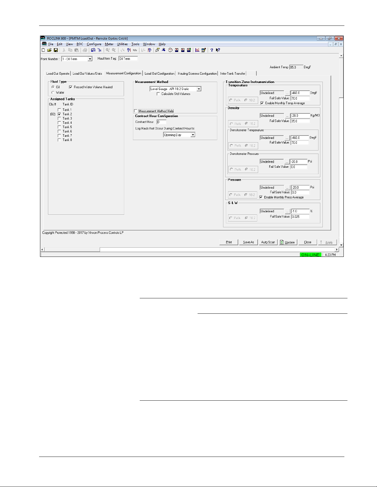
Tank Manager User Manual (for ROC800-Series and FloBoss 107)
Revised June-2019 Configuration 83
Figure 3-19. Load Out Screen – Measurement Configuration tab
1. Review the values in the following fields.
Field
Description
Fluid Type
Defines the fluid type to be hauled from this Load
Terminal. The fluid type will be either oil or water.
Record Water
Volume
Hauled
When enabled and an interfaced
(oil and water) gauge is used, a
drop in the water level during an oil
haul will result in that water
quantity being recorded. This is
only true when the interface level is
above the unsafe zone for the
tank, as defined by the Load Line
Elevation.
Note: This field displays only if
you select the fluid type Oil
as the primary fluid.
Page 88

Tank Manager User Manual (for ROC800-Series and FloBoss 107)
84 Configuration Revised June-2019
Field
Description
Record Oil
Volume
Hauled
When enabled and an interfaced
(oil and water) gauge is used, a
drop in the oil level during a water
haul will result in that oil quantity
being recorded. This is only true
when the interface level is above
the unsafe zone for the tank, as
defined by the Load Line Elevation.
Note: This field displays only if
you select the fluid type
Water as the primary fluid.
Assigned Tanks
Defines the tanks that this terminal instance can
haul from. If one tank is selected, the object# to haul
will automatically fill with the tank number for a haul.
When more than one tank can be hauled from for
the terminal, you must enter the tank number they
wish to haul from.
Measurement Methods
Defines the method and calculations to be used for hauls from this load
out terminal. Depending on the selection, additional configuration fields
will become visible.
Level Gauge –
API 12.1.1
The haul volume will be determined based on
changes to the level of the tank being hauled from. A
single reading of the tank level is taken at the
beginning of the haul. Readings for each of the fluid
properties (temperature, pressure, density, S&W)
are also recorded on the haul opening. When the
haul is completed, a closing tank level is taken, and
a second closing set of fluid properties (optional) is
recorded. These values are then used to determine
the haul volume, based on the API MPMS Chapter
12.1.1 methodology.
Level Gauge –
API 18.2 Static
The haul volume will be determined based on
changes to the level of the tank being hauled from.
Tank level readings are taken at the opening and
closing of the haul. Fluid properties (temperature,
pressure, density, S&W) are recorded during the
haul according to the API MPMS 18.2
methodology. When the haul is completed, the final
haul volume is determined according to the
calculations outlined in the API MPMS 18.2
standard.
Meter – ROC800L
The load out terminal will read meter accumulation
and fluid properties from an associated ROC800L
Liquid Meter. Fluid property values (temperature,
pressure, density, S&W) are averaged using flow
weighing over the period of the haul. These
averages are then reported for the haul. The final
haul volume is based on the quantities recorded
from the ROC800L Liquid Meter.
Page 89

Tank Manager User Manual (for ROC800-Series and FloBoss 107)
Revised June-2019 Configuration 85
Field
Description
Meter – API 18.2
Dynamic
The haul volume is determined using a live meter
which is configured and dedicated to the load out
terminal. Fluid property values (temperature,
pressure, density, S&W) are recorded at various
periods throughout the haul, in accordance with the
methodology outlined in API MPMS 18.2. The final
haul volume is calculated using the meter readings
and fluid property values recorded during the haul,
using the calculations outlined in the API MPMS
18.2 standard.
Calculate Std
Volumes
Enables the program to have the tank manager
calculate haul volumes at standard conditions (i.e.
60 deg F, and 0.0 psig), also known as the Gross
Standard Volume (GSV). For this option to be used,
the required instrumentation (temperature, pressure,
density) must be configured
Measurement
Method Help
Enables the program to view the additional details
about the processes used for the various
measurement methods, to help the operator select
the proper option. This field is provided for
informational purposes only, it performs no
configuration for the load out terminal. See below:
Contract Hour Configuration
Contract Hour
The tank object includes multiple daily
accumulators. This selection determines the hour of
the day when the Today values rollover and become
the yesterday values. Valid values include 0 through
23.
Note: These fields are a duplicate of those on the
Alarms and Rollovers tab of the Tank.
Log Hauls that
Occur During
Contract Hours
to:
It is possible that a haul will begin before a contract
hour, and end afterwards, with the contract hour
occurring during the haul. When this situation
occurs, this option determines to which day the
totals from that haul will belong.
Note: These fields are a duplicate of those on the
Alarms and Rollovers tab of the Tank.
Transition Zone Instrumentation
Temperature
Click to display the Select TLP screen and define
a TLP to hold the temperature input value.
Page 90

Tank Manager User Manual (for ROC800-Series and FloBoss 107)
86 Configuration Revised June-2019
Field
Description
Fail Safe Value
Indicates the value to be used for
the temperature when the live
instrument reading is considered
invalid.
Enable Monthly
Temp Average
Enables the program to record
the rolling average of the product
temperature.
Note: This field is displayed
when the Temperature
input TLP has been
defined.
FWA / 18.2
When a live instrument is
defined, this option determines if
a flow weighted average should
be recorded over the period of
the haul, or if single values
(snapshots) should be recorded
at the appropriate times, in
accordance with the API MPMS
18.2 standard.
Note: This field is displayed
when the measurement
method is set to Level
Gauge – API 18.2 Static
or Meter – API 18.2
Dynamic.
Density
Click to display the Select TLP screen and define
a TLP to hold the Top gauge input value.
Fail Safe Value
Indicates the value to be used
for the density when the live
instrument reading is
considered invalid.
FWA / 18.2
When a live instrument is
defined, this option determines
if a flow weighted average
should be recorded over the
period of the haul, or if single
values (snapshots) should be
recorded at the appropriate
times, in accordance with the
API MPMS 18.2 standard.
Note: This field is displayed
when the measurement
method is set to Level
Gauge – API 18.2
Static or Meter – API
18.2 Dynamic.
Densitometer
Temperature
Click to display the Select
TLP screen and define a TLP to
hold the densitometer
temperature input value.
Fail Safe
Value
Indicates the value to be used
for the density temperature
when the live instrument
reading is considered invalid.
Page 91

Tank Manager User Manual (for ROC800-Series and FloBoss 107)
Revised June-2019 Configuration 87
Field
Description
FWA / 18.2
When a live instrument is
defined, this option determines
if a flow weighted average
should be recorded over the
period of the haul, or if single
values (snapshots) should be
recorded at the appropriate
times, in accordance with the
API MPMS 18.2 standard.
Note: This field is displayed
when the measurement
method is set to Level
Gauge – API 18.2
Static or Meter – API
18.2 Dynamic.
Densitometer
Pressure
Click to display the Select
TLP screen and define a TLP
to hold the densitometer
pressure input value.
Fail Safe
Value
Indicates the value to be used
for the density pressure when
the live instrument reading is
considered invalid.
FWA / 18.2
When a live instrument is
defined, this option determines
if a flow weighted average
should be recorded over the
period of the haul, or if single
values (snapshots) should be
recorded at the appropriate
times, in accordance with the
API MPMS 18.2 standard.
Note: This field is displayed
when the
measurement method
is set to Level Gauge
– API 18.2 Static or
Meter – API 18.2
Dynamic.
Pressure
Click to display the Select TLP screen and define
a TLP to hold the pressure input value.
Fail Safe Value
Indicates the value to be used
for the pressure when the live
instrument reading is
considered invalid.
Enable Monthly
Press Average
Enables the program to
record the rolling average of
the product pressure.
Note: This field is displayed
when the Pressure
input TLP has been
defined.
Page 92

Tank Manager User Manual (for ROC800-Series and FloBoss 107)
88 Configuration Revised June-2019
Field
Description
FWA / 18.2
When a live instrument is
defined, this option
determines if a flow weighted
average should be recorded
over the period of the haul,
or if single values
(snapshots) should be
recorded at the appropriate
times, in accordance with the
API MPMS 18.2 standard.
Note: This field is
displayed when the
measurement
method is set to
Level Gauge – API
18.2 Static or Meter
– API 18.2
Dynamic.
S&W
Click to display the Select TLP screen and define
a TLP to hold the S & W input value.
Fail Safe Value
Indicates the value to be used
for the sediment and water
when the live instrument
reading is considered invalid.
FWA / 18.2
When a live instrument is
defined, this option
determines if a flow weighted
average should be recorded
over the period of the haul, or
if single values (snapshots)
should be recorded at the
appropriate times, in
accordance with the API
MPMS 18.2 standard.
Note: This field is displayed
when the
measurement method
is set to Level Gauge
– API 18.2 Static or
Meter – API 18.2
Dynamic.
2. Proceed to Section 3.5.4 to review the Load Out Configuration tab.
Page 93

Tank Manager User Manual (for ROC800-Series and FloBoss 107)
Revised June-2019 Configuration 89
3.5.4 PMTM Load Out – Load Out Configuration Tab
Use this screen to configure aspects of the load out terminal which are
not directly related to the measurement, such as the automated loading
valve, a divert valve, load out timeout / expiration values, and the
optional ticket printer. Many of these features are typically associated
with a LACT unit, although they may apply to other load out terminal
applications.
Figure 3-20. Load Out Screen – Load Out Configuration tab
1. Review the values in the following fields.
Field
Description
Divert Valve Control
Enable
Select to enable diverter valve control. If no
diverter valve is available in the system, this
option should remain unchecked.
Auto
Select this option to automatically read a live
S&W value from the input defined in the BSW
/ Divert Valve Control Definition field.
Manual
Select this option to manually enter a fixed
S&W value, when a live S&W instrument is
not available.
Page 94

Tank Manager User Manual (for ROC800-Series and FloBoss 107)
90 Configuration Revised June-2019
Field
Description
Status
This read only field provides an indication of
the “Merchantable” status of the product. The
follow indications can be provided: Idle, Non-
Merchantable, Merchantable, TSD – Divert
Time Exceeded, PSD – Max TSDs have
Occurred, Invalid S&W Signal.
BSW / Divert
Valve Control
Definition
Click to display the TLP screen and define
a live S&W input value, which will be read
periodically through the haul and will
determine the behavior of the divert valve.
Value
When a BSW / Divert Valve Control Definition
is configured, this field will show the current
value of the live input. When the BSW / Divert
Valve Control Definition is left undefined, this
is the field where a manual S&W value should
be entered.
Max Allowable
S&W
Enter a percentage (between 0% and 100%)
that is the maximum allowed sediment and
water percentage reading that is allowed to
occur during a haul. If the live value exceeds
this limit during a haul (for the number of
confirmation delay sections), the flow should
be diverted.
Merchantable
Confirmation
Delay Seconds
If the S&W % exceeds the Max Allowed
S&W%, flow is diverted immediately since the
oil is deemed Non-Merchantable. Should the
S&W % fall below the Max Allowed S&W %,
the Merchantable Confirmation Delay Timer
starts. If the S&W % remains below the Max
Allowed S&W % for the entire Merchantability
Delay Time, the divert valve will be triggered
to stop diverting flow, since the oil has been
deemed Merchantable.
Max Diverted Run
Time Minutes
Should the flow become diverted, this defines
the maximum number of minutes that the
diverted state is allowed, before the haul
should be aborted (shut down via a TSD).
NonMerchantable
PSD Duration
Hours
If a PSD occurs due to too many failed haul
attempts, the system will no longer allow
additional hauls. Hauling can resume after the
number of hours configured in this field are
passed.
Max
NonMerchantable
TSDs
If multiple TSD (Temporary Shut Down)
events occur sequentially (due to a nonmerchantable product state) while attempting
to perform a haul, this is only allowed to occur
the number of times as configured in this
field. Should the maximum number of TSDs
occur, then the loadout will enter a state of
PSD (Permanent Shut Down), and will be
unable to proceed with new hauls for a
duration of time.
Valve Output
(1=To
Truck/0=Diverted)
Provides an indication of the current state of
the diverter valve.
Page 95

Tank Manager User Manual (for ROC800-Series and FloBoss 107)
Revised June-2019 Configuration 91
Field
Description
Valve TLP
Used to define a discrete output point which
controls the diverter valve.
Click to display the Select TLP screen and
define a TLP to hold the Top gauge input
value.
Automated Loading Output
Status
Shows the status of the output valve. A status
of 0 means the valve is closed. A status of 1
means the valve is open.
Output Def:
Click to display the select TLP screen and
define a TLP to hold the Top gauge input
value.
Ticket Printer
Selection
Define the printer type to be used.
Timers for Haul Screen and Flow Indication
Inactivity Minutes
Defines the time allowed where no action has
been taken and no flow has been detected
before closing out a haul in progress. This
timer will be reset when flow is detected or
when you complete any action during the
haul. You also extend the haul, which adds
the inactivity minutes to the current time
remaining before a closeout.
Warning X B4
Expiry
Defines the time remaining in which a warning
will be given to you. When the inactivity
minutes are below this value, you will be
notified with a warning.
Hauling Flow
Indication Period
Number of consecutive seconds required
before the program recognizes that flow is in
progress during a haul. If the appearance of
flow from an associated meter exists for less
than this time period, that state is not
considered to be an indication of flow.
On Demand Automated Hauling
This feature allows for metered hauls to begin automatically. When
the TLP selected (typically a discrete input) is True (1), the load out
terminal will enter into hauling mode and will remain in the hauling
mode until the TLP is False (0) for the time configured in the Close
Out Delay Seconds. This allows a Tank Manager load out terminal to
calculate hauls without the need for an operator to log into the HMI
(a one button haul configuration option).
Discrete Demand
Signal
Click to select a discrete signal which will
be used to initiate hauls when it transitions
from 0 to 1, and will determine the end of the
haul when it transitions from 1 to 0. This is
typically a discrete input (DI).
Close-Out Delay
Secs
Sets the number of seconds that the Discrete
Demand Signal must remain at a value of
False (0), before a haul in progress will end.
Page 96

Tank Manager User Manual (for ROC800-Series and FloBoss 107)
92 Configuration Revised June-2019
Field
Description
Normal Haul
Volume
Specifies the typical expected volume for a
haul. For example, the average truck size can
be entered. This value is used to determine
when a haul reaches certain completion
points, such as ¼ completed, ½ completed,
etc. This can be overridden by the operator,
who can enter a pre-set load volume at the
start of a haul.
TSD Permissive
Reset
Requires that the operator must manually
reset a Temporary Shut Down (TSD) for the
load out terminal.
TSDs Require
Reset to Resume
Haul
If a TSD stops the haul, and this option is
enabled, the operator will have to manually
press a reset button to clear the TSD and
continue a haul. When this occurs, the Reset
button is automatically presented to the
operator on the HMI and the Load Out
Operate tab.
2. Proceed to Section 3.5.5 to configure the Hauling Screens
Configuration tab.
3.5.5 PMTM Load Out – Hauling Screens Configuration Tab
Use this screen to configure what fields are displayed during a haul and
which fields require you to enter values when hauling.
Figure 3-21. Load Out Screen – Hauling Screens Configuration tab
Page 97

Tank Manager User Manual (for ROC800-Series and FloBoss 107)
Revised June-2019 Configuration 93
1. Review the values in the following fields.
Field
Description
Driver Login Screen
Company Code
Defines the numerical credentials of the
company. When the driver enters a company
code on the HMI, the program verifies and
validates the code against the ROC Hauler
Database (see Section 3.6) and shows the
result in the Company Verified field.
The program displays the validated company
name in the Company Verified field.
Note: The default text of “Company Code”
can be changed to a different
customized text label. The custom text
entered here will be presented to the
operator on the HMI as the label for
this field.
Driver Pin
Defines the driver’s numerical credentials.
When the driver enters a driver code on the
HMI, the program verifies and validates the
code against the Hauler Companies Database
(see Section 3.6) and shows the result in the
Driver Verified field.
Note: The default text of “Driver PIN” can be
changed to a different customized text
label. The custom text entered here will
be presented to the operator on the
HMI as the label for this field.
Ticket Number
Provides the ticket number. This optional 20-
character field may be contractually required
by an agreement with the owner. The program
records this information in the haul log.
Visible: When you enable this option, this
field becomes visible on the Load Out screen
for you to enter values. However, you are not
required to enter a value unless you enable
Mandatory.
Mandatory: When you enable this option, you
must enter a non-zero number into this field
for you to advance to the next stage of the
haul.
Duplicates Allowed: When you enable this
option, the same ticket number is allowed to
be used multiple times. If this option is not
enabled, then a ticket number which has
already been entered is not allowed.
Note: The default text of “Ticket Number” can
be changed to a different customized
text label. The custom text entered
here will be presented to the operator
on the HMI as the label for this field.
Page 98

Tank Manager User Manual (for ROC800-Series and FloBoss 107)
94 Configuration Revised June-2019
Field
Description
Truck Number
Provides the truck number. This optional 20character field may be contractually required
by an agreement with the owner. The program
records this information in the haul log.
Visible: When you enable this option, this
field becomes visible on the Load Out screen
for you to enter values. However, you are not
required to enter a value unless you enable
Mandatory.
Mandatory: When you enable this option, you
must enter a non-zero number into this field.
You will not be able to advance to the next
stage of the haul without entering a value in
mandatory fields.
Note: The default text of “Truck Number” can
be changed to a different customized
text label. The custom text entered
here will be presented to the operator
on the HMI as the label for this field.
Fluid Characteristics
Visible: When you enable this option, this field becomes visible on
the Load Out screen for you to enter values. However, you are not
required to enter a value unless you enable Mandatory.
Mandatory: When you enable this option, you must enter a nonzero number into this field. You will not be able to advance to the
next stage of the haul without entering a value in mandatory fields.
This field shows only when you enable Visible. These values
override the manual entries as defined on the Measurement
Configuration if don’t define an input. If you define an input, it takes
precedence over the Default values you enter on the Hauling
Screens Configuration tab.
Visible: When you enable this option, this field becomes visible on
the Load Out screen for you to enter values. However, you are not
required to enter a value unless you enable Mandatory.
Temp Config
Defines the temperature visibility (Open and
Close), default value (Open), and mandatory
requirement (Close) selections.
Note: The fields shown in this section will
vary, depending on the measurement
type selected for the load out on the
Measurement Configuration tab. When
the API 12.1.1 option is selected, open
and closing fields are shown. When
one of the API 18.2 options are
selected, fields for ¼ Temp, ½ Temp,
and ¾ Temp will be shown. When the
Meter - ROC800L option is selected,
temperature values are read from the
ROC800L liquid meter, and no fields
will be shown.
Open Temp
The available selections are:
Visible
Default
See Fluid Characteristics field
for the definitions.
Page 99

Tank Manager User Manual (for ROC800-Series and FloBoss 107)
Revised June-2019 Configuration 95
Field
Description
Close Temp
The available selections are:
Visible
Mandatory
See Fluid Characteristics field
for the definitions.
Pressure Config
Defines the pressure visibility (Open and
Close), default value (Open), and mandatory
requirement (Close) selections.
Note: The fields shown in this section will
vary, depending on the measurement
type selected for the load out on the
Measurement Configuration tab. When
the API 12.1.1 option is selected, open
and closing fields are shown. When
one of the API 18.2 options are
selected, fields for ¼ Press and ¾
Press will be shown. When the Meter ROC800L option is selected, pressure
values are read from the ROC800L
liquid meter, and no fields will be
shown.
Open Press
The available selections are:
Visible
Default
See Fluid Characteristics field
for the definitions.
Close Press
The available selections are:
Visible
Mandatory
See Fluid Characteristics field
for the definitions.
S&W Config
Defines the S&W visibility (Open and Close),
default value (Open), and mandatory
requirement (Close) selections.
Note: The fields shown in this section will
vary, depending on the measurement
type selected for the load out on the
Measurement Configuration tab. When
the API 12.1.1 option is selected, open
and closing fields are shown. When
one of the API 18.2 options are
selected, fields for ¼ S&W, 3rd S&W, ¾
S&W, 4th S&W and 5th S&W will be
shown. When the Meter - ROC800L
option is selected, sediment and water
values are read from the ROC800L
liquid meter, and no fields will be
shown.
Open S&W
The available selections are:
Visible
Default
See Fluid Characteristics
field for the definitions.
Page 100

Tank Manager User Manual (for ROC800-Series and FloBoss 107)
96 Configuration Revised June-2019
Field
Description
Close S&W
The available selections are:
Visible
Mandatory
See Fluid Characteristics
field for the definitions.
Density Config
Defines the density visibility (Open and
Close), default value (Open), and mandatory
requirement (Close) selections.
Note: The fields shown in this section will
vary, depending on the measurement
type selected for the load out on the
Measurement Configuration tab. When
the API 12.1.1 option is selected, open
and closing fields for the density,
density temperature, and density
pressure are shown. When one of the
API 18.2 options are selected, fields for
½ Density, ½ Temp, and ½ Press will
be shown. When the Meter ROC800L option is selected, density
values are read from the ROC800L
liquid meter, and no fields will be
shown.
Open Density
The available selections are:
Visible
Mandatory
See Fluid Characteristics
field for the definitions.
Close Density
The available selections are:
Visible
Mandatory
See Fluid Characteristics
field for the definitions.
Open Temp
The available selections are:
Visible
Mandatory
See Fluid Characteristics
field for the definitions.
Close Temp
The available selections are:
Visible
Mandatory
See Fluid Characteristics
field for the definitions.
Open Press
The available selections are:
Visible
Mandatory
See Fluid Characteristics
field for the definitions.
Close Press
The available selections are:
Visible
Mandatory
See Fluid Characteristics
field for the definitions.
 Loading...