

Remote Automation Solutions Surface Control Manager User Manual (FB107+ROC800) Manuals & Guides
Page 1

Remote Automation Solutions
Part D301759X012
January 2017
Surface Control Manager User Manual
(for ROC800-Series and
FloBoss™ 107 Controllers)
Page 2

Surface Control Manager Program User Manual (ROC800-Series and FloBoss 107)
ii Revised January-2017
Revision Tracking Sheet
January 2017
This manual may be revised periodically to incorporate new or updated information. The revision date
of each page appears at the bottom of the page opposite the page number. A change in revision date
to any page also changes the date of the manual that appears on the front cover. Listed below is the
revision date of each page (if applicable):
Page
Revision
All Pages
January-2017
All Pages
August-2016
Initial release
September-2014
Page 3

Surface Control Manager Program User Manual (ROC800-Series and FloBoss 107)
Revised January-2017 Contents iii
Contents
Chapter 1 – Introduction 1
1.1 Scope and Organization ..................................................................................................................... 1
1.2 Product Overview ............................................................................................................................... 2
1.3 Program Requirements ...................................................................................................................... 2
1.3.1 License Key .......................................................................................................................... 3
Chapter 2 – Installation 5
2.1 Installing the License Key .................................................................................................................. 5
2.1.1 Installing the License Key for the ROC800 .......................................................................... 5
2.1.2 Installing the License Key for the FB107 .............................................................................. 6
2.1.3 Verifying the License Key Installation (for ROC800) ............................................................ 7
2.2 Downloading the Program .................................................................................................................. 8
2.2.1 Surface Control Program ...................................................................................................... 8
2.2.2 PMCB Calculation Blocks Program .................................................................................... 12
2.3 MPU Loading Threshold (ROC800) ................................................................................................. 16
Chapter 3 – Configuration 17
3.1 PMSC Action Blocks Screen ............................................................................................................ 18
3.2 PMSC Utilities Screens .................................................................................................................... 25
3.2.1 PMSC Utilities Screen – PMSC Effects Tab ...................................................................... 27
3.2.2 PMSC Utilities Screen – Time Count Tab .......................................................................... 29
3.2.3 PMSC Utilities Screen – Accumulators/Outputs Tab ......................................................... 32
3.2.4 PMSC Utilities Screen – Alarm Blocks Tab ........................................................................ 35
3.2.5 PMSC Utilities Screen – Action Block Domain Statuses Tab ............................................ 38
3.3 PMCB Calculation Blocks ................................................................................................................ 42
3.4 Saving the Configuration .................................................................................................................. 47
3.5 Sample Configurations ..................................................................................................................... 48
3.5.1 Controlling a Pump based on Tank Level .......................................................................... 48
3.5.2 Connecting Two Blocks with an AND Statement ............................................................... 49
3.5.3 Connecting Two Block with an OR Statement ................................................................... 51
3.5.4 Setting Up a Class B Bypass ............................................................................................. 54
3.5.5 Creating a Timed Maintenance Bypass ............................................................................. 56
Chapter 4 – Reference 59
4.1 Point Type 68/28: Action Blocks ...................................................................................................... 60
4.2 Point Type 71/31: Utilities ................................................................................................................ 68
4.3 Point Type 218: Calculation Blocks (for ROC800) ........................................................................... 75
4.4 Point Type 27/39: Calculation Blocks (for FB107) ........................................................................... 78
Appendix A – PMCB Calculation Blocks – Supported Functions 87
A.1 Calculations: Rules and Guidelines ................................................................................................. 87
A.1.1 Execution Order .................................................................................................................. 87
A.1.2 Order of Operators ............................................................................................................. 87
A.1.3 Parentheses ....................................................................................................................... 88
A.1.4 Operands ............................................................................................................................ 88
Page 4

Surface Control Manager Program User Manual (ROC800-Series and FloBoss 107)
iv Contents Revised January-2017
A.2 Operators ......................................................................................................................................... 89
A.2.1 Mathematical Operators ..................................................................................................... 89
A.2.2 Comparison Operators ....................................................................................................... 90
A.2.3 Bitwise Operators ............................................................................................................... 91
A.2.4 Logical Operators ............................................................................................................... 92
A.3 Functions ......................................................................................................................................... 92
A.3.1 AND(): Logical AND ........................................................................................................... 92
A.3.2 OR(): Logical OR ................................................................................................................ 93
A.3.3 Boolean Calculations using AND(), OR() and NOT(!) Operators ....................................... 93
A.3.4 ABS(): Absolute Value ........................................................................................................ 93
A.3.5 INT(): Integer Value ............................................................................................................ 94
A.3.6 MOD(): Modulus ................................................................................................................. 94
A.3.7 POW(): Raise To The Power Of ......................................................................................... 95
A.3.8 SUM(): Summation ............................................................................................................. 95
A.3.9 MIN(): Minimum Value ........................................................................................................ 95
A.3.10 MAX(): Maximum Value ..................................................................................................... 95
A.3.11 IIF(): Inline IF ...................................................................................................................... 96
A.3.12 BFI(): Boolean FAN-IN ....................................................................................................... 96
A.3.13 BFO(): Boolean FAN-OUT ................................................................................................. 96
A.3.14 FOR(): FOR Loop ............................................................................................................... 98
Page 5

Surface Control Manager Program User Manual (ROC800-Series and FloBoss 107)
Revised January-2017 Introduction 1
Chapter 1 – Introduction
Caution
When implementing control using this product, observe best industry
practices as suggested by applicable and appropriate environmental,
health, and safety organizations. While this product can be used as A
safety component in a system, it is NOT intended or designed to be the
ONLY safety mechanism in that system.
This chapter describes the structure of this manual and presents an
overview and installation instructions of the Surface Control Manager
program for the ROC800-Series Remote Operations Controller and the
FloBoss™ 107 Flow Computer.
Note: The Surface Control Manager program (v407_00_XXXblk.tar)
comes with PMCB Calculation Blocks (Display #218) for
ROC800. For FloBoss 107, it is a separate program. For
installation procedures, refer to Section 2.2.2 – PMCB
Calculation Blocks Program for details.
1.1 Scope and Organization
This document serves as the user manual for the Surface Control
Manager program, which is intended for use in a ROC800-Series
(ROC800) and FloBoss 107 (FB107). This manual describes how to
download, install, and configure the Surface Control Manager program
(referred to as the “Surface Control program” or “the program”
throughout the rest of this manual). You access and configure this
program using ROCLINK™ 800 Configuration Software (version 2.30
or greater) loaded on a personal computer (PC) running Microsoft®
Windows® 2000 (with Service Pack 2), Windows XP (with Service
Pack 3), Windows Vista™ (32-bit), or Windows 7 (32-bit and 64-bit).
The sections in this manual provide information in a sequence
appropriate for first-time users. Once you become familiar with the
procedures and the software, the manual becomes a reference tool.
This manual has the following major sections:
Chapter 1 – Introduction
Chapter 2 – Installation
Chapter 3 – Configuration
Chapter 4 – Reference
Appendix A – PMCB Calculation Blocks – Supported Functions
This manual assumes that you are familiar with the ROC800 or FB107
and its configuration. For more information, refer to the following
manuals:
FloBoss
™
107 Flow Manager Instruction Manual (Part
D301232X012)
Page 6

Surface Control Manager Program User Manual (ROC800-Series and FloBoss 107)
2 Introduction Revised January-2017
ROC800-Series Remote Operations Controller Instruction Manual
(Part D301217X012)
ROCLINK
™
800 Configuration Software User Manual (for
FloBoss™ 107) (Part D301249X012)
ROCLINK
™
800 Configuration Software User Manual (for
ROC800-Series) (Part D301250X012)
ROCLINK
™
800 Configuration Software User Manual (for
ROC800L) (Part D301246X012)
1.2 Product Overview
The two main functional areas on a well pad are the well itself
(“downhole”) and the equipment on the surrounding ground (“surface
management”). “Surface control” refers to the ability to manage both
the control logic of that equipment as well as any maintenance bypass
requirements for that equipment and surface shut-in of wells. The
Surface Control Management application enables you to configure the
ROC800 or the FB107 to perform logical control and maintenance
bypass using “action blocks.” Action blocks are configurable program
components that drive effects (such as valves opening or closing). The
FB107 program supports 48 action blocks; the ROC800 programs
support 48, 96, 144 or 192 action blocks. Additionally, a quartet of
utilities accompanies each action block. These utilities provide the
sequential effects for an action block, monitor run times (to calculate
run and down times for air compressors, engines, and other equipment),
accumulate values (for today, yesterday, this month, previous month,
and for a running period), and provide configurable outputs (analog
outputs, pulse outputs, etc.).
The Surface Control Program has an added feature – PMCB Calculation
Blocks. This program enables you to specify complex mathematical or
logical (Boolean) equations for entry in a free-form style. These
equations typically would either not be suited (too complex) for entry in
Action Blocks or Cause & Effect, or possibly you prefer to save Action
Blocks by processing all math and some logic problems in the PMCB
Calculation Blocks program.
1.3 Program Requirements
The Surface Control Manager program is compatible with version 3.52
(or greater) of the ROC800 firmware, version 1.31 (or greater) of the
ROC800L firmware, version 1.61 (or greater) of the FB107 firmware, and
with version 2.30 (or greater) of the ROCLINK 800 software.
Program specifics include:
Note: Load only one version of the program, depending on your action
blocks and utilities requirements:
Page 7

Surface Control Manager Program User Manual (ROC800-Series and FloBoss 107)
Revised January-2017 Introduction 3
The PMSC_v407_00_48blk.tar program file supports 48
action blocks, 4 calc blocks and 16 utilities and installs in a
ROC800 which requires only 1 license.
The PMSC_v407_00_96blk.tar program file supports 96
action blocks, 8 calc block and 32 utilities and installs in a
ROC800 which requires 2 licenses.
The PMSC_v407_00_144blk.tar programs file supports 144
action blocks, 12 calc blocks and 48 utilities and installs in a
ROC800 which requires 3 licenses.
The PMSC_v407_00_192blk.tar programs file supports 192
action blocks, 16 calc blocks and 64 utilities and installs in a
ROC800 which requires 4 licenses.
The PMSC_v407_XX_5.bin supports 48 action blocks and
16 utilities and installs in an FB107 which requires only 1
license.
File Name
Target Unit/
Version
User
Defined
Point (UDP)
Flash Used
(in bytes)
DRAM Used
(in bytes)
ROCKLINK
800 Version
Display
Number
PMSC_v407_00_48blk.tar
ROC800 3.52
ROC800L 1.31
68, 71, 218
130,345
172,032
2.30
68, 71, 218
PMSC_v407_00_96blk.tar
ROC800 3.52
ROC800L 1.31
68, 71, 218
130,345
172,032
2.30
68, 71, 218
PMSC_v407_00_144blk.tar
ROC800 3.52
ROC800L 1.31
68, 71, 218
130,345
172,032
2.30
68, 71, 218
PMSC_v407_00_192blk.tar
ROC800 3.52
ROC800L 1.31
68, 71, 218
130,345
172,032
2.30
68, 71, 218
PMSC_v407_XX_5.bin
FB107 1.61
28, 31
62,808
16,384
2.30
28, 31
PMCB_v400_01_3.bin
FB107 1.61
27
32,651
16,384
2.30
27
PMCB_v400_01_6.bin
FB107 1.61
39
32,651
16,384
2.30
39
For information on viewing the memory allocation of user programs,
refer to the following manuals;
ROCLINK
™
800 Configuration Software User Manual (for
FloBoss™ 107) (Part D301249X012)
ROCLINK
™
800 Configuration Software User Manual (for
ROC800-Series) (Part D301250X012)
ROCLINK
™
800 Configuration Software User Manual (for
ROC800L) (Part D301246X012)
1.3.1 License Key
License keys, when matched with valid license codes, grant access to
applications such as the Surface Control Manager program.
Page 8

Surface Control Manager Program User Manual (ROC800-Series and FloBoss 107)
4 Introduction Revised January-2017
For ROC800, the term “license key” refers to the physical piece of
hardware that can contain up to seven different licenses (refer to Figure
1). Each ROC800 can have none, one, or two license keys installed. If
you remove a license key after enabling an application, the firmware
disables the task from running. This prevents unauthorized execution of
protected applications in a ROC800.
DOC0422A
J1
U1
Figure 1-1. License Key
Note: The Surface Control Manager program for ROC800 requires up
to 3 PMSC license keys depending on your program
requirement. Refer to the Note on Section 1.3 for more
information regarding the program and its corresponding license
key requirements.
For FB107, Remote Automation Solutions delivers software licenses on
secure USB drives. You must install the PMSC license key to use the
Surface Control Manager program.
Page 9

Surface Control Manager Program User Manual (ROC800-Series and FloBoss 107)
Revised January-2017 Installation 5
Chapter 2 – Installation
This section provides instructions for installing the Surface Control
Manager program into the ROC800 or FB107. Read Section 1.3 of this
manual for program requirements.
2.1 Installing the License Key
Section 2.1.1 provides license key installation instructions for ROC800
and Section 2.1.2 provides license key installation instructions for
FB107.
2.1.1 Installing the License Key for the ROC800
If you order the Surface Control Manager program for a new FB107 or
ROC800, your FB107 or ROC800 is delivered with the license key
installed. Go to Section 2.2.
If you order the program for an existing ROC800, you must install the
license key yourself.
Caution
Failure to exercise proper electrostatic discharge precautions, such as
wearing a grounded wrist strap may reset the processor or damage
electronic components, resulting in interrupted operations.
When working on units located in a hazardous area (where explosive
gases may be present), make sure the area is in a non-hazardous state
before performing these procedures. Performing these procedures in a
hazardous area could result in personal injury or property damage.
To install a license key:
1. Remove power from the ROC800.
2. Remove the wire channel cover.
3. Unscrew the screws from the Central Processing Unit (CPU)
faceplate.
4. Remove the CPU faceplate.
5. Place the license key in the appropriate terminal slot (P4 or P6) in
the CPU.
Figure 2-1. License Key Installation
6. Press the license key into the terminal unit until it is firmly seated
(refer to Figure 2).
7. Replace the CPU faceplate.
DOC0423A
Page 10

Surface Control Manager Program User Manual (ROC800-Series and FloBoss 107)
6 Installation Revised January-2017
8. Replace the screws on the CPU faceplate.
9. Replace the wire channel cover.
10. Restore power to the ROC800.
11. Proceed to Section 2.1.3 to verify your license keys.
2.1.2 Installing the License Key for the FB107
A license is required to use the Surface Control Manager program. To
install a license on the FB107:
1. Insert the USB license key in a USB port on your PC.
2. Select Utilities > License Key Administrator > Transfer Between
DEVICE and KEY from the ROCLINK 800 menu bar. The
Transfer Licenses Between a Device and a Key screen displays:
Figure 2-2. Transfer Licenses Between a Device and a Key
Note: This screen has three sections. The upper portion (Licenses
on Device) shows any software licenses installed on the
FB107. The middle portion (Licenses on Key) shows
software licenses on the license key. The lower portion of the
screen (License Key Event Log) provides a rolling log of the
last eight events related to this license key.
3. Select the key-based license you want to transfer to the FB107
(PMSC, as shown in Figure 2-2).
4. Click Move to Device. ROCLINK moves the license from the key
to the FB107 and updates the screen.
Page 11

Surface Control Manager Program User Manual (ROC800-Series and FloBoss 107)
Revised January-2017 Installation 7
Figure 2-3. License Installed
Note: An FB107 can hold up to six different licenses, although you
can install only one instance of each license on the FB107.
When you click Move to Device, ROCLINK 800 moves
only one instance of the license onto the FB107 and
automatically decreases the license quantity on the USB key
by one.
5. Verify the license name displays in the Licenses on Device section
of the screen. Proceed to Section 2.2 to download the user program.
2.1.3 Verifying the License Key Installation (for ROC800)
After you install the license key, you can verify whether the ROC800
recognizes the key. From the ROCLINK 800 screen, From the
ROCLINK 800 screen, select Utilities > License Key Administrator.
The License Key Administrator screen displays:
Page 12

Surface Control Manager Program User Manual (ROC800-Series and FloBoss 107)
8 Installation Revised January-2017
Figure 2-4. Transfer Licenses Between a Device and a Key
2.2 Downloading the Program
Section 2.2.1 provides downloading instructions of the Surface Control
Program for ROC800 or FB107 and Section 2.2.2 downloading
instructions of the PMCB Calculation Blocks for FB107.
2.2.1 Surface Control Program
This section provides instructions for installing the program into the
Flash memory on the ROC800 or FB107.
To download the program using ROCLINK 800 software:
1. Connect the ROC800 or the FB107 to your computer using the LOI
port.
2. Start and logon to ROCLINK 800.
3. Select Utilities > User Program Administrator from the
ROCLINK menu bar. The User Program Administrator screen
displays (see Figure 2-5):
Page 13

Surface Control Manager Program User Manual (ROC800-Series and FloBoss 107)
Revised January-2017 Installation 9
Figure 2-5. User Program Administrator
4. Click Browse in the Download User Program File frame. The Select
User Program File screen displays (see Figure 2-6).
Note: If you install the program in the ROC800, choose any
available user program slot. If you use FB107, the program
installs automatically in user program slot 5.
5. Select the path and user program file to download from the CD-
ROM. (Program files are typically located in the Program Files
folder on the CD-ROM). As Figure 2-6 shows, the screen lists all
valid user program files with the .tar (for ROC800) or .bin (for
FB107) extension:
Page 14

Surface Control Manager Program User Manual (ROC800-Series and FloBoss 107)
10 Installation Revised January-2017
Figure 2-6. Select User Program File
6. Click Open to select the program file. The User Program
Administrator screen displays:
Figure 2-7. User Program Administrator
7. Click Download & Start to begin loading the selected programs.
The following message displays:
Page 15

Surface Control Manager Program User Manual (ROC800-Series and FloBoss 107)
Revised January-2017 Installation 11
Figure 2-8. Confirm Download
8. Click Yes to begin the download. When the download completes the
following message displays:
Figure 2-9. ROCLINK 800 Download Confirmation
9. Click OK. The User Program Administrator screen displays (see
Figure 2-10). Note that:
The User Programs Installed in Device frame identifies the
installed program(s).
The Status field indicates that the program is running.
Page 16

Surface Control Manager Program User Manual (ROC800-Series and FloBoss 107)
12 Installation Revised January-2017
Figure 2-10. User Program Administrator
10. Click Close. The ROCLINK 800 screen displays and the download
is complete. Proceed to Chapter 3, Configuration.
2.2.2 PMCB Calculation Blocks Program
This section provides instructions for installing the PMCB Calculation
Blocks program into the Flash memory on the FB107.
Notes:
The PM Calculation Blocks program installs separately into the
FB107.
There are two versions of the PMCB Calculation Blocks program
are included. Installation and operation are identical between
programs, but they use different point type locations, different
display numbers, and are loaded into different program slots on the
FB107. PMCB_v400_01_3.bin loads into user program location 3
and User Defined Point (UDP) 27. PMCB_v400_01_6.bin loads into
user program location 6 and User Defined Point (UDP) 39. Install
the program version that avoids point type conflicts with currently
installed programs.
This document shows the installation of PMCB_v400_01_3.bin. The
installation process and functionality is the same for all version of
the Calculation Blocks program.
To download the program using ROCLINK 800 software:
1. Connect the FB107 to your computer using the LOI port.
Page 17

Surface Control Manager Program User Manual (ROC800-Series and FloBoss 107)
Revised January-2017 Installation 13
2. Start and logon to ROCLINK 800.
3. Select Utilities > User Program Administrator from the
ROCLINK menu bar. The User Program Administrator screen
displays (see Figure 2-11):
Figure 2-11. User Program Administrator
4. Click Browse in the Download User Program File frame. The Select
User Program File screen displays (see Figure 2-12).
5. Select the path and user program file to download from the CD-
ROM. (Program files are typically located in the Program Files
folder on the CD-ROM). As Figure 2-12 shows, the screen lists all
valid user program files with the .BIN extension:
Figure 2-12. Select User Program File
Page 18

Surface Control Manager Program User Manual (ROC800-Series and FloBoss 107)
14 Installation Revised January-2017
6. Click Open to select the program file. The User Program
Administrator screen displays. As shown in Figure 2-13, note that
the Download User Program File frame identifies the selected
program and that the Download & Start button is active:
Figure 2-13. User Program Administrator
7. Click Download & Start to begin loading the selected programs.
The following message displays:
Figure 2-14. Confirm Download
Note: For the FB107, ROCLINK800 assigns program positions
based on memory allocations. For this reason, the
PMCB_v400_01_3.bin program automatically installs as
program 3. For PMCB_v400_01_6.bin program
automatically installs as program 6.
Page 19

Surface Control Manager Program User Manual (ROC800-Series and FloBoss 107)
Revised January-2017 Installation 15
8. Click Yes to begin the download. During the download, the program
performs a warm start, creates an event in the event log, and when
the download completes displays the following message:
Figure 2-15. ROCLINK 800 Download Confirmation
9. Click OK. The User Program Administrator screen displays (see
Figure 2-16). Note that:
The User Programs Installed in Device frame identifies the
loaded program.
The Status field indicates that the program is running.
Figure 2-16. User Program Administrator
10. Click Close and proceed to Section 3.3 – PMCB Calculation Blocks
to configure the program.
Page 20

Surface Control Manager Program User Manual (ROC800-Series and FloBoss 107)
16 Installation Revised January-2017
2.3 MPU Loading Threshold (ROC800)
To maximize the performance of your ROC800 device, always verify
the performance of specific application combinations before using them
in the field to ensure the MPU load typically remains below 85% with
peak MPU loading levels below 95%.
To check the current MPU load at any time, select ROC > Information
> Other Information and review the value in the MPU loading field.
Figure 2-17. MPU Loading
Page 21

Surface Control Manager Program User Manual (ROC800-Series and FloBoss 107)
Revised January-2017 Configuration 17
Chapter 3 – Configuration
After you have loaded the Surface Control Manager program on the
FB107 or the ROC800, you configure the program using three programspecific screens:
PMSC Action Blocks
PMSC Utilities
PMCB Calculation Blocks
To configure the program (after logging onto ROCLINK 800 and
successfully installing the program), proceed through the program
screens as shown in the following sections.
You can access all the program-specific screens from the main
ROCLINK 800 screen:
Note: The configuration screens of the Surface Control Manager
program for both the ROC800 and the FB107 platforms are
identical.
Figure 3-1. ROCLINK 800
Page 22

Surface Control Manager Program User Manual (ROC800-Series and FloBoss 107)
18 Configuration Revised January-2017
3.1 PMSC Action Blocks Screen
The screen has five main sections:
Block Logic Operation– Use this section to define the logic for each
action block.
Bypasses– Use this section to configure temporary overrides for the
result of the raw action block logic.
Chain– Use this section to logically link one action block to another.
Action Output– Use this section to define any actions to be
performed when the action block is “true”. These actions can
include writing to a defined parameter, moving a value, or shutting
down another aspect of an associated user program, such as Tank
Manager or Well Optimization.
Alarm Logging– Use this section to generate alarms in the device
alarm log, based on the status changes of the action block.
To access this screen:
1. From the Directory Tree, select User Program > Program #1,
PMSC_v407_00_48blk.
2. Double-click Display #68, PMSC Action Blocks.
Note: This section shows how to access the access the Action
Blocks screen for the ROC800. To access the Action Blocks
for FB107, double-click Display #28, PMSC Action Blocks.
3. Double-click #1, Block 1. The PMSC Action Blocks screen
displays:
Note: Depending on the device (ROC800 or FB107) and the
version of the program installed, you may have up to 144 of
these screens, one for each action block.
Page 23

Surface Control Manager Program User Manual (ROC800-Series and FloBoss 107)
Revised January-2017 Configuration 19
Figure 3-2. PMSC Action Blocks Screen
4. Review the values in the following fields:
Field
Description
Block Logic Operation
Block Tag
Sets the action block tag name.
Enable
Enables the action block when checked.
Input Pt Def
Sets the TLP source of the input value.
Input Value
Displays the input’s live value.
Operator
Selects a mathematical or logical operator
from the dropdown list. Click to select a
valid operator:
GT (>) – If the Input Value is greater than the
Set Pt Value for the Delay Preset time, the
block is set true.
GE (>=) – If the Input Value is greater than or
equal to the Set Pt Value for the Delay
Preset time, the Block is set true.
LT (<) – If the Input Value is less than the Set
Pt Value for the Delay Preset time, the block
is set true.
LE (<=) – If the Input Value is less than or
equal to the Set Pt Value for the Delay
Preset time, the block is set true.
Page 24

Surface Control Manager Program User Manual (ROC800-Series and FloBoss 107)
20 Configuration Revised January-2017
Field
Description
EQ (==) – If the Input Value is equal to the
Set Pt Value for the Delay Preset time, the
block is set true.
NE (!=) – If the Input Value is not equal to the
Set Pt Value for the Delay Preset time, the
block is set true.
Watchdog – Monitors the Input Value, if it
does not change for the Delay Preset time,
the block is set true.
Trip on Change – If the Input Value is
different than the Set Pt Value, the block is
set true.
pEdge – Monitors the Input Value for a
transition from 0 to 1, block is set true for one
scan.
nEdge - Monitors the Input value for a
transition from 1 to 0, block is set true for one
scan.
Bitwise AND (&) – Compares each bit in the
Input Value to the Set Pt Value. If both bits
are true (1), the block is set true.
Bitwise OR – Compares each bit in the Input
Value to the Set Pt Value. If either bit
matches, the block is set true.
Add (+) – Adds Input Value to Set Pt Value
and displays the results in the Math Result
field.
Subtract (-) – Subtracts the Set Pt Value
from the Input Value and displays the results
in the Math Result field.
Multiply (*) – Multiplies the Input Value by
Set Pt Value and displays the results in the
Math Result field.
Divide (/) – Divides the Input Value by the
Set Pt Value and displays the results in the
Math Result field.
Modulus (%) – Or remainder of the Input
Value divided by the Set Pt Value. Example:
17 modulus 3 = 2, or 17/3 = 5 with a
remainder of 2 displayed in the Math Result
field.
Soft Input Reset Timer – Monitors the Input
Value for a transition from 0 to 1. Once this
transition occurs the block is set true and a
time delay starts for the amount of seconds
specified in the Delay Preset field. When the
timer expires the block is set to false and the
Input Value is forced back to a zero.
Set Pt Def
Selects the TLP source of the Set Pt Value.
Set Pt Value
Shows the value of the point defined in the
Set Pt Def field. If you leave this field
undefined, you can manually enter this value.
Page 25

Surface Control Manager Program User Manual (ROC800-Series and FloBoss 107)
Revised January-2017 Configuration 21
Field
Description
Preset
Sets the delay in seconds. This delay is either
for an on delay for logic functions or for soft
input rest timer. (See function description
above.)
Elapsed
Shows the time delay that has elapsed, starts
counting up from zero to the Preset time and
status changes when the Preset time is
reached.
Deadband / Math
Result
Sets the deadband for clearing the
comparator logic or displays the Math Result
for math functions.
Block Trip Status
(Before Bypass)
Displays the logic block trip indicator based
only on the block logic operation, before any
bypasses are applied.
Bypasses
Types Currently
Active
Shows the bypasses that are currently active.
Demand Bypass
(Latched)
Activates the manual latched bypass when
selected. This value could be set or removed
from an FST or from an action block.
Remote
Bypasses
Allows you to browse other action blocks to be
used to define bypass functionality. When the
remote action block is true, the bypass for this
block is true.
Note: If the Use Action Block is un-checked,
click to select a TLP in the system.
Valid bypass types are:
Latched – Bypassed while the Remote
Bypass block is true.
Class B – Bypassed for the amount of time in
the Class B Timer field once the Remote
Bypass block is true.
Class C - Bypassed until the block clears
once the Remote Bypass block is true.
Class B w/C override - Bypassed for the
amount of time in the Class B Timer field or
unless the Block clears before the timer
expires once the Remote Bypass block is
true.
Class B Timer
Seconds – Preset
Sets the timer for Class B bypass.
Class B Timer
Seconds –
Elapsed
Shows the elapsed time for Class B bypass.
Class C
Deadband / Arm
Delay –
Deadband EU
Sets the deadband for Class C bypass.
Class C
Deadband / Arm
Delay – Preset
Sets the timer for Class C bypass.
Page 26

Surface Control Manager Program User Manual (ROC800-Series and FloBoss 107)
22 Configuration Revised January-2017
Field
Description
Class C
Deadband / Arm
Delay – Elapsed
Shows the elapsed time for Class C bypass.
Block Trip Status
(After Bypass)
Shows the combined status of the logic block
and the bypass block. For example, if the
logic block is true and the bypass is not in
effect, then the status is true. If the logic block
is true and the bypass is in effect, then the
status is false.
Chain
To
Allows you to browse a previous action block
to compare results with based on the chain
type.
Type
Sets the logic of chain. Click to select an
available logic type:
AND – If the chained block and current block
are true, the Chain Trip Status is true.
OR – If the chained block or current blocks
are true, the Chain Trip Status is true.
NAND – If the chained block and current block
are false, the Chain Trip Status is true.
XOR Either – If one of the chained block and
current block is true and the other false, the
Chain Trip Status is true.
XOR Local – If the chained block is set to
false and current block is set to true, the
Chain Trip Status is true.
XOR Remote – If current block is set to false
and chained block is set to true, the Chain
Trip Status is true.
Seal-In – If the current block is set to true and
the previous block or the current chain status
are set to true, the Chain Status is true until
the current block status after bypass is false
PWM Lo-Duty – If the current block is set to
true and the previous block is false, the Chain
Status is true for one second then toggles
false for the remaining seconds in the Chain
Delay Preset time. The cycle repeats while
the condition remains the same, the Preset
time must be more than two seconds
PWM-Hi-Duty – If the current block is set to
true and the previous block is false, the Chain
Status is false for one second then toggles
true for the remaining seconds in the Chain
Delay Preset time. The cycle repeats while
the condition remains the same, the Preset
time must be more than two seconds
Is End of Chain
Indicates when this block is the end of a chain
of previous blocks.
Delay
Sets the delay Preset timer and shows the
Elapsed time.
Page 27

Surface Control Manager Program User Manual (ROC800-Series and FloBoss 107)
Revised January-2017 Configuration 23
Field
Description
OR Chain First
Out
Shows the number of the action block that is
tripped in a chain of or blocks.
Chain Trip Status
Shows the number of the action block that is
tripped in a chain of OR blocks.
Note: This field displays only when the Chain
Type is OR.
Action Output
Block/Chain Trip
Selects the status that trips the output. Valid
values are:
True if Block True – Output is driven true if
the Block Trip Status (After Bypass) is true on
this action block.
True if Chain True – Output is driven true if
the Chain Status is true on this action block.
True if Either True – Output is driven true if
the Block Trip Status (After Bypass) or the
Chain Status is true on this action block.
True if Both True – Output is driven true if
the Block Trip Status (After Bypass) and the
Chain Status is true on this action block.
Instance Trip
Status
Shows the status of the Output Action.
Type
Selects the type of Output desired from this
action block. Valid values are:
PSD (Permanent Shutdown) – When selected
a submenu of available Applications
(Domains) displays allowing you to select the
instance from the other applications you wish
to permanently shutdown. A manual reset is
required after the shutdown occurs.
TSD (Temporary Shutdown) – When selected
a submenu of available Applications
(Domains) displays allowing you to select the
instance from the other applications you wish
to temporarily shutdown. An automatic reset
occurs after the shutdown clears.
DO (Binary Action) – Allows you to select a
Binary Field to which the signal is sent.
Discrete signals can be sent in the following
format:
Force 1True & 0False
Force 0True & 1False
Poke 1True
Poke 0True
Poke 1True & 0False
Poke 0True & 1False
Force 1True & Poke 0False
Force 0True & Poke 1False
Force 1True
Force 0True
Page 28

Surface Control Manager Program User Manual (ROC800-Series and FloBoss 107)
24 Configuration Revised January-2017
Field
Description
Move Value – Two Functions:
1. When using Math Operators, the Result is
moved to the defined Output TLP.
2. When using Comparator Operators, the
Input Value is moved to the Output TLP
when the block is true.
VAL (to Result Reg) – Pushes the value in
the Output TLP into the internal Result
Register of PMSC.
SAV (from Result Reg) – Pulls the internal
Result Register value from PMSC and pushes
it into the Output TLP.
No Action – No output action will take place
when the block is set true.
SSD Domains
Provides the ability to shutdown aspects of
other associated programs (such as Tank
Manager or Well Optimization), based on the
result of the action block. Once a domain has
been selected, the instances of that domain
for which the block action should apply must
also be selected.
PMTM Wells – Sets either a (Permanent
Shutdown) PSD or a (Temporary Shutdown)
TSD to the associated Well defined in PM
Tank Manager, Allocated Well Values/Trip
Point.
PMTM Loadouts – Sets either a PSD or TSD
to the associated Haul HMI/Station
Permissive. A PSD stops a haul in progress
and a TSD pauses a haul in progress.
PMv 3.3x Wells – Sets either a PSD or TSD to
the associated Production Manager version 3
wells.
PMWO Wells – Sets either a PSD or TSD to
the associated well in PMWO 4.x.
PMSC Effects – Sets a PSD or TSD to the
associated effect in PMSC Utilities.
Note: The SSD Domains are only visible
when the Action Output Type has been
set to PSD or TSD.
Alarm Logging
Alarm Logging
Activates logging in the ROC Alarm Log if the
action block sets (if the Log Inst Trips option is
selected) or clears (if the Log Inst Clears
option is selected).
First Out
Shows the First Out tag of the action block
that was first tripped in a chain for which the
current block is a part.
5. Click Apply to save your changes.
6. Click Close to return to the ROCLINK 800 screen. Proceed to
Section 3.2 to configure the PMSC Utilities Screen.
Page 29

Surface Control Manager Program User Manual (ROC800-Series and FloBoss 107)
Revised January-2017 Configuration 25
3.2 PMSC Utilities Screens
The PMSC Utilities screen allows you to configure the following tabs:
PMSC Effects
Time Count
Accumulators/Outputs
Alarm Blocks
Action Block Domain Statuses
To access this screen:
1. From the Directory Tree, select User Program > Program #1,
PMSC_v407_00_48blk.
2. Double-click Display #71, PMSC Utilities.
Note: This section shows how to access the access the Utilities
screen for the ROC800. To access the Action Blocks for
FB107, double-click Display #31, PMSC Utilities.
3. Double-click #1, Inst 1. The PMSC Utilities screen displays:
Page 30

Surface Control Manager Program User Manual (ROC800-Series and FloBoss 107)
26 Configuration Revised January-2017
Figure 3-3. PMSC Utilities Screen
4. Follow Section 3.2.1 through Section 3.2.4 to configure the PMSC
Effects, Time Count, Accumulations/Outputs, and the Action Block
Domain Statuses tabs.
Page 31

Surface Control Manager Program User Manual (ROC800-Series and FloBoss 107)
Revised January-2017 Configuration 27
3.2.1 PMSC Utilities Screen – PMSC Effects Tab
Use this screen (which displays when you first access the PMSC
Utilities screen) to configure various aspects of an effect triggered by an
action block. Each effect represents a particular action that is taken
when the action blocks that are linked to it are tripped or cleared. The
action that is taken is the writing of a value out to a user defined
parameter. Different values to be written are defined for when the effect
is tripped vs. when the effect is not tripped. This allows for creating of
custom actions, such as driving a discrete valve or a panel annunciation.
In addition to configuring effects, this tab allows you to configure
outputs separately. You can:
Control the output by multiple action blocks.
Write values to analog type controls (analog outputs, PID setpoints,
and so on).
Page 32

Surface Control Manager Program User Manual (ROC800-Series and FloBoss 107)
28 Configuration Revised January-2017
Figure 3-4. PMSC Utilities Screen – PMSC Effects tab
1. Review and complete the values in the following fields:
Field
Description
Effect Tag
Identifies the specific effect being defined.
Enable
Enables the effect.
PtDef
Sets the output to be driven.
Value When
Tripped
Sets the value to be driven to the PtDef when
the effect is Tripped (true).
Value When Not
Tripped
Sets the value to be driven to the PtDef when
the effect is Not Tripped (false).
Page 33

Surface Control Manager Program User Manual (ROC800-Series and FloBoss 107)
Revised January-2017 Configuration 29
Field
Description
Output the Value
When Not
Tripped
Allows the output to be either driven or not
driven when the effect is false. You typically
use this option when the effect needs to be
manually reset. Select this option to enable
the effect to drive the signal each way. If you
do not select this option, the signal is driven
only when the effect is true.
Assert Output
Continuously
During
Selects how to assert effect output to the
parameter defined by the PtDef field. When
the “Neither State” option is selected, then the
output parameter is written to one time on
state change, and not written to again (until
the next state change). When the other
options are selected (“Tripped State Only”,
“UnTripped State Only”, and “Both States”),
the configured value is written to the output
parameter continuously.
Click to select valid options.
Neither State
Tripped State Only
UnTripped State Only
Both States
Cur Outp Value
Shows the current output value.
Effect Trip Status
Indicates the status of the effect trip. Valid
values are 1 (tripped, red box with yellow
letters; active) and 0 (not tripped, blue box
with white letters; inactive).
First-Out Int#
Shows the numerical values of the action
block that first tripped this effect.
First-Out Tag
Shows the tag of the action block that tripped
this effect.
Trips Require
Reset
The user program automatically checks this
box upon a PSD type trip that is connected to
the effect.
The user program automatically unchecks
this box upon a TSD type trip that is
connected to the effect.
A user can override the automatic selection
after the trip has occurred (check or uncheck
it).
When the box is checked, even though action
block that caused the trip is in the cleared
(normal) state, the effect will stay tripped until
a reset action is performed.
When the box is unchecked the effect is
cleared as soon as any tripped action blocks
(connected to the effect) are cleared.
Page 34

Surface Control Manager Program User Manual (ROC800-Series and FloBoss 107)
30 Configuration Revised January-2017
Field
Description
Remote Reset
Command TLP
Click to select a TLP in the ROC800 or FB107
used to reset this effect. For example, a TLP
you might select is a discrete input or soft
point value. When the effect is ready to be
reset, any positive value written to the TLP
performs the reset.
The same remote TLP may be used to reset
several different effects.
The user program automatically resets the
value of the remote TLP back to zero after
processing.
Note: This field shows only if you check or
select the Trips Require Reset option.
Reset Command
Identifies a local reset field which can be
mapped to HMIs, etc. Any positive value
entered will cause a reset action. The value in
this field is reset to zero after processing. This
field is entirely independent from the “Remote
Reset Command TLP” field. The two fields
logically act as an “OR” in resetting the
effect.
2. Click Apply to save any changes you have made to this screen.
3. Proceed to Section 3.2.2 to configure the Utilities Screen – Time
Count tab.
3.2.2 PMSC Utilities Screen – Time Count Tab
Use this screen to configure the time counter of the Surface Control
manager program. Use this utility to set “timers” for equipment on a
well site to remind you to perform preventive maintenance (such as for
a compressor after a certain number of hours).
To access this screen:
1. Select the Time Count tab on the PMSC Utilities screen. The
Time Count screen displays:
Page 35

Surface Control Manager Program User Manual (ROC800-Series and FloBoss 107)
Revised January-2017 Configuration 31
Figure 3-5. PMSC Utilities Screen – Time Count tab
Page 36

Surface Control Manager Program User Manual (ROC800-Series and FloBoss 107)
32 Configuration Revised January-2017
2. Review the values in the following fields:
Field
Description
Counter Tag
Identifies the specific counter being defined.
Enable
Select to enable the time counter.
Run-Time Pt Def
Sets the point to be monitored to define if the
On Counter or the Off Counter Advances.
This value is compared using the following
logical functions:
GT (>)
GE (>=)
LT (<)
LE (<=)
EQ (==)
NE (!=).
Value
Defines the value to be compared to the RunTime Pt Def.
Cur Status
Indicates if comparison statement written
above is True (ON) or False (OFF).
Update Interval
Defines how often the accumulating counters
update their associated values in the ROC.
The calculation always runs every second, but
to save MPU load the updating accumulators
are only written out to the ROC points based
on this parameter.
Mins Tdy
This display-only field shows Accumulated
On minutes and Off minutes Today.
Mins Ydy
This display-only field shows Accumulated
On minutes and Off minutes Yesterday.
Hours Tdy
This display-only field shows Accumulated
On hours and Off hours Today.
Hours Ydy
This display-only field shows Accumulated
On hours and Off hours Yesterday.
Pct Tdy
This display-only field shows Percent of time
On and Off Today.
Pct Ydy
This display-only field shows Percent of time
On and Off Yesterday.
Mins TMon
This display-only field shows Accumulated
On minutes and Off minutes This Month.
Mins PMon
This display-only field shows Accumulated
On minutes and Off minutes Previous Month.
Hours TMon
This display-only field shows Accumulated
On hours and Off hours This Month.
Hours PMon
This display-only field shows Accumulated
On hours and Off hours Previous Month.
Pct TMon
This display-only field shows Percent of time
On and Off This Month.
Pct PMon
This display-only field shows Percent of time
On and Off Previous Month.
Contact Hr
Sets the hour, in military hour format, at which
the accumulators roll up the Days On and Off
Times.
Page 37

Surface Control Manager Program User Manual (ROC800-Series and FloBoss 107)
Revised January-2017 Configuration 33
Field
Description
Clear Now!
Select this option to clear all accumulators
and reset them to zero. The system
automatically clears this field checkbox is auto
cleared and the accumulation for On and Off
time begin anew.
3. Click Apply to save any changes you have made to this screen.
4. Proceed to Section 3.2.3 to configure the PMSC Utilities Screen –
Accumulators/Output tab.
3.2.3 PMSC Utilities Screen – Accumulators/Outputs Tab
The functionality on this screen changes, depending on the mode you
select. There are 4 possible modes:
Accumulate a Rate – This function provides daily, monthly, and
running total accumulation for a flowrate you specify. The flowrate
comes from a metering device providing a rate in the form of an
analog or HART input, a pulse input EU value rate, or a flow
calculation you implement. The flowrate integrates once per second,
and that incremental amount of accumulation adds to the daily,
monthly, and running totals.
Accumulate a Running Total – This functionally also provides
daily, monthly, and running totals. The totals, however comes from
a smart meter or other device that provides an incremental
accumulator value (commonly provided to the ROC800 or FB107
from a Modbus connection). The program determines the increment
per second based on this accumulator input. The incremental values
are added to the daily, month, and running totals. If applicable, the
rollover of this incremental accumulator input value is automatically
determined.
Output a 4-20mA Signal – This option provide a method to link a
process variable from the internal database of the device to an
Analog Output (AO) point, therefore providing a 4-20 mA signal.
The signal can be of any form, but is commonly used for flowrate
values, valve positions, or other process variables you send to
another device or system.
Output a Pulse at an Interval – Allows you to generate a
reoccurring pulse signal to another devices or system. Typically, this
is used to send a pulse (via a ROC800 or FB107 discrete output) that
represents an accumulated amount of flow. For example, If you have
a daily flowrate in MCF, you can generate a pulse for every unit of
MCF that is measured by the ROC800 or FB107.
To access this screen:
1. Select the Accumulators/Outputs tab on the PMSC Utilities screen.
The Accumulation/Outputs screen displays:
Page 38

Surface Control Manager Program User Manual (ROC800-Series and FloBoss 107)
34 Configuration Revised January-2017
Figure 3-6. PMSC Utilities Screen – Accumulators/Outputs tab
2. Review the values in the following fields:
Field
Description
Accum/Out Tag
Identifies the specific accum/output being
defined.
Enable
Enables this instance of the
Accumulator/Output.
Page 39

Surface Control Manager Program User Manual (ROC800-Series and FloBoss 107)
Revised January-2017 Configuration 35
Field
Description
Mode
Selects the type of accumulator or output for
this instance. Click to select a valid option:
Accumulate a Rate – Accumulates the flow
rate defined in the Input Def field.
Accumulate a Running Total – Accumulates
the accumulated value defined in the Input
Def field. This should be an accumulator that
does not reset each day at contract hour. Rollover is handled internally every scan period.
Output a 4-20ma Signal – Sends the value
specified in the Input Def field to the AO
defined in the Output Def and forces the 4-20
mA signal to update.
Generate a Pulse at an Interval – Sends a
Pulse Command to the DO defined in the
Output Def parameter when the flow rate
defined in the Input Def parameter
accumulates a value greater than the value
specified in the DO Out Pulse Interval.
Input Def
Defines the input used in the mode selected.
Time Basis
Defines the frequency of the flow rate in the
Input Definition. Available time periods are
Second, Minute, Hour and Day. For all modes
besides the 4-20 mA output mode.
Output Def
Sets the output to be used. In the 4-20 mA
Output and Pulse Output mode this should
point to an AO or a DO. In the Flow
Accumulation mode it should point to a
softpoint value. The selected softpoint value
defines the first of seven consecutive values
to store the following accumulators:
1 = Today
2 = Yesterday
3 = This Month
4 = Previous Month
5 = Running Accum
6 = This Hour
7 = Previous Hour
Update Interval
Defines how often the accumulators update
their associated values in the ROC. The
calculation always runs every second, but to
save MPU load the program only writes
updated accumulator values to the ROC
points based on this parameter.
Contact Hour
Sets the hour, in military times, at which the
accumulators roll up the Days Accumulated
Flows.
Cur Month
Shows the chronological number of the
current month. Valid values are 1-12.
Cur Day
Shows the chronological number of the
current day. Valid values are 1-31.
Page 40

Surface Control Manager Program User Manual (ROC800-Series and FloBoss 107)
36 Configuration Revised January-2017
Field
Description
Flags
Provides functions for managing and clearing
the accumulator values being stored in an
associated SoftPoint.
Click to select the option:
Normal Operations – Operates as configured
Force End Of Day – Forces all Accumulators
to roll up at that instant and restart their daily
at zero
Force end of Month – Forces all Accumulators
to roll up at that instance, including Monthly
Flush Running Accum – Clears the daily
Accumulator but does not roll up
Cold Start Accumulator Set – Clears all
Accumulators
3. Click Apply to save any changes you have made to this screen.
4. Proceed to Section 3.2.4 to configure the PMSC Utilities Screen –
Alarm Blocks tab.
3.2.4 PMSC Utilities Screen – Alarm Blocks Tab
Use this screen to configure the alarm point of the Surface Control
manager program. Use this utility to set three alarm point mechanisms
per instance.
To access this screen:
1. Select the Alarm Blocks tab on the PMSC Utilities screen. The
Alarm Blocks screen displays:
Page 41

Surface Control Manager Program User Manual (ROC800-Series and FloBoss 107)
Revised January-2017 Configuration 37
Figure 3-7. PMSC Utilities Screen – Alarm Blocks tab
2. Review the values in the following fields:
Field
Description
Alarm Tag
Sets a 10-character (for the ROC800) or an 8-
character (for the FB107) alarm identification.
Alarm Point
Definition
Click to designate the TLP for the alarm to
be monitored. This field shows a valid entry
(not Undefined) the value of the specified
point will be displayed in the field on the right
(Alarm Point Current Value) whether alarming
is enabled or not.
Alarm Point
Current Value
Displays the value of the point specified to the
left (Alarm Point Definition). If the Alarm Point
Definition is Undefined or Scanning is set to
“Disable” the current value or any user-
entered value here will remain unchanged.
Page 42

Surface Control Manager Program User Manual (ROC800-Series and FloBoss 107)
38 Configuration Revised January-2017
Field
Description
Alarm Enable
Selects to Enable the Alarm Point Current
Value is monitored for alarm conditions and
the alarm code can be a positive number (an
alarm condition exists).
Selects to Disable the alarm code will always
be zero.
Alarm Type
Selects to Analog, the Alarm Point Current
Value is compared to each of the four
possible alarm type setpoints (Low, Low Low,
High, High High) for setting alarms along with
the Deadband value for clearing alarms.
Selects to Boolean, the Alarm Point Current
Value is compared Boolean Alarm. A Boolean
Alarm is generated when the current value
equals the Boolean Alarm “Set on” value.
Note: Zero and One are the only legal values
for the Boolean Alarm Type. If the
Alarm Point Current value can possibly
be any other value the Alarm Type
should be set to Analog as no Boolean
alarm will be generated for values no
exactly equal to the Boolean Alarm
“Set on” value.
SRBX
RBX on Set
Selects to Enable an RBX attribute is set for
the alarm when any “Alarm Set” is logged.
This causes any Comm Port with SRBX Mode
Enabled to process the alarm setting.
Selects Disable….
RBX on Clear
Selects to Enable an RBX attribute is set for
the alarm when any “Alarm Clear” is logged.
This causes any Comm Port with SRBX Mode
Enabled to process the alarm setting.
Selects Disable….
Scanning
Selects to Enable the Alarm Point Current
Value is the value of the point defined in the
Alarm Point Definition field.
Selects to Disable the program and will not
change the Alarm Point Current Value.
High High
Sets the High High alarm value. The Alarm
Point Current Value is greater than or equal to
the High High value. The alarm remains in
effect until the Alarm Point Current Value
goes less than High High Value minus the
Deadband value.
Note: This field displays only if you select
Analog in the Alarm Type.
High
Sets the High alarm value. The Alarm Point
Current Value is greater than or equal to the
High value. The alarm remains in effect until
the Alarm Point Current Value goes less than
High Value minus the Deadband value.
Note: This field displays only if you select
Analog in the Alarm Type.
Page 43

Surface Control Manager Program User Manual (ROC800-Series and FloBoss 107)
Revised January-2017 Configuration 39
Field
Description
Low
Sets the Low alarm value. The Alarm Point
Current Value is less than or equal to the Low
value. The alarm remains in effect until the
Alarm Point Current Value goes greater than
Low Value plus the Deadband value.
Note: This field displays only if you select
Analog in the Alarm Type.
Low Low
Sets the Low Low alarm value. The Alarm
Point Current Value is less than or equal to
the Low Low value. The alarm remains in
effect until the Alarm Point Current Value
goes greater than Low Low Value plus the
Deadband value.
Note: This field displays only if you select
Analog in the Alarm Type.
Boolean Alarm
Sets the boolean value that will determine
when an alarm is triggered. For example, if
the input alarm point definition is a discrete
value where normal operation is a value of
“0”, the option for “Set on 1” should be
selected.
Note: This field displays only if you select
Boolean in the Alarm Type.
Deadband
Sets the Deadband value.
Note: This field displays only if you select
Analog in the Alarm Type.
Alarm Code
This display-only field shows the alarm
values:
1 = Low Alarm
2 = Low Low Alarm
4 = High Alarm
8 = High High Alarm
32 = Boolean Alarm
128 = Manual Alarm
3. Click Apply to save any changes you have made to this screen.
4. Proceed to Section 3.2.5 to configure the PMSC Utilities Screen
– Action Block Domain Statuses tab.
3.2.5 PMSC Utilities Screen – Action Block Domain Statuses Tab
The Action Block Domain Statuses reports the health of other
associated user programs (if installed), such as Tank Manager or Well
Optimization. To access this screen:
To access this screen:
1. Select the Action Block Domain Statuses tab on the PMSC
Utilities screen. The Action Block Domain Statuses screen displays:
Page 44

Surface Control Manager Program User Manual (ROC800-Series and FloBoss 107)
40 Configuration Revised January-2017
Figure 3-8. PMSC Utilities Screen – Action Block Domain Statuses tab
2. Review the values in the following fields:
Field
Description
Point Number
Selects the logical instance you want to
configure.
Page 45

Surface Control Manager Program User Manual (ROC800-Series and FloBoss 107)
Revised January-2017 Configuration 41
Field
Description
Tank Mgr Well #
1
Shows the status of any Tank Manager
Allocation Wells. The number beside the field
name refers to the point number of the Tank
Manager allocation well instance you are
viewing. This is not necessarily related to the
PMSC Effect or utilities on this display (of the
same logical instance). If you change the
Point Number, this field can provide the
status of up to 4, 8, or 12 wells, depending on
the version of the Tank Manager program you
install.
Note: The Tank Manager program supports
up to 12 allocation wells, thus the
numbers greater than 12 have no
configuration effect.
SSD Set
This section is checked if the System Shut
Down (SSD) is set for this well.
PSD Set
This section is checked if the Permanent
Shutdown (PSD) is set to this well.
TSD Set
This section is checked if the Temporary
Shutdown (TSD) is set to this well.
Trip Code
Sets the numerical code of First Out action
block that tripped this instance.
Tank Mgr Load
Out # 1
Shows the status of any Tank Manager Truck
Load Out Terminals. The number beside the
field name refers to the point number of the
Tank Manager Load Out Terminal instance
you are viewing. This is not necessarily
related to the PMSC Effect or utilities on this
display (of the same logical instance). If you
change the Point Number, this field can
provide the status of up to 6 loading terminals
in the ROC800 and 2 loading terminals in the
FB107.
Note: The Tank Manager program supports
up to 2 (for FB107) or 6 (for ROC800)
loading terminals, thus the numbers
greater than 2 (for FB107) or 6 (for
ROC800) have no configuration effect.
SSD Set
This section is checked if the System Shut
Down (SSD) is set to this Load Terminal.
PSD Set
This section is checked if the Permanent
Shutdown (PSD) is set to this Load Terminal.
TSD Set
This section is checked if the Temporary
Shutdown (TSD) is set to this Load Terminal.
Trip Code
Sets the numerical code of First Out Action
Block that tripped this instance.
Page 46

Surface Control Manager Program User Manual (ROC800-Series and FloBoss 107)
42 Configuration Revised January-2017
Field
Description
Well Opt Mgr
Well # 1
Shows the status of any Well Optimization
Manager Wells. The number beside the field
name refers to the point number of the well
instance you are viewing. This is not
necessarily related to the PMSC Effect or
utilities on this display (of the same logical
instance). As you change the Point Number,
this field can provide the status of up to 4, 8,
or 12 wells, depending on the version of the
Well Optimization Manager program you
install.
Note: The Well Optimization Manager
program supports up to 12 optimization
wells, thus the numbers greater than
12 have no configuration effect.
SSD Set
This section is checked if the System Shut
Down (SSD) is set to this well.
PSD Set
This section is checked if the Permanent
Shutdown (PSD) is set to this well.
TSD Set
This section is checked if and (Temporary
Shutdown) TSD is set to this well.
Trip Code
Sets the numerical code of First Out Action
Block that tripped this instance.
PM v3.3x Well # 1
Shows the status of any Production Manager
version 3 Wells. The number beside the field
name refers to the point number of the well
instance you are viewing. This is not
necessarily related to the PMSC Effect or
utilities on this display (of the same logical
instance). If you change the Point Number at
the top of this display, this field can provide
the status of up to 4 wells provided by
Production Manager version 3.
Notes:
The Well Optimization Manager program
supports up to 4 optimization wells, thus
the numbers greater than 4 have no
configuration effect.
These domain statuses are provided for
backwards compatibility with previous
versions of Production Manager. If
Production Manager version 3.3x is in
use, then these domain statuses are
applicable. If Well Optimization Manager
is in use (or no Well Optimization
program), then these domain statuses
are NOT applicable. This is not valid if
you install both the PM v3.3x and the
Well Optimization Manager programs in
the same unit.
SSD Set
This section is checked if the System Shut
Down (SSD) is set to this well.
PSD Set
This section is checked if the Permanent
Shutdown (PSD) is set to this well.
Page 47

Surface Control Manager Program User Manual (ROC800-Series and FloBoss 107)
Revised January-2017 Configuration 43
Field
Description
TSD Set
This section is checked if and Temporary
Shutdown (TSD) is set to this well.
Trip Code
Sets the numerical code of First Out Action
Block that tripped this instance.
PMSC Effect # 1
Shows the domain status of PMSC Effects.
The number beside the field name refers to
the point number of the instance or utilities
you view. This can be up 12, 24, or 36
depending on your user program version. See
program specifics note in Section 1.3.
SSD Set
This section is checked if the System Shut
Down (SSD) is set to this Effect.
PSD Set
This section is checked if the Permanent
Shutdown (PSD) is set to this Effect.
TSD Set
This section is checked if the Temporary
Shutdown (TSD) is set to this Effect.
Trip Code
Sets the numerical code of First Out action
block that tripped this instance.
3. Click Apply to save any changes you have made to this screen.
4. Proceed to Section 3.3 to configure the PMCB Calculation Blocks.
3.3 PMCB Calculation Blocks
The PMCB Calculation Blocks display allows the configuration of up to
four inputs/input arrays and up to three calculations per instance. A 10-
character tag field is provided for each input and calculation.
To access this screen:
1. From the Directory Tree, select User Program > Program #1,
PMSC_v407_00_48blk.
2. Double-click Display #218, PMCB Calculation Blocks.
Note: This section shows how to access the access the PMCB
Calculation Blocks screen for the ROC800. To access the
PMCB Calculation Blocks for FB107, double-click Display
#27, PMCB Calculation Blocks or Display #39, PMCB
Calculation Blocks.
3. Double-click #1, Calculation Block 1. Select the Calc Blocs tab
and the screen displays:
Page 48

Surface Control Manager Program User Manual (ROC800-Series and FloBoss 107)
44 Configuration Revised January-2017
Figure 3-9. PMCB Calculation Blocks- Calc Blocks tab
Page 49

Surface Control Manager Program User Manual (ROC800-Series and FloBoss 107)
Revised January-2017 Configuration 45
4. Review and complete the values in the following fields:
Field
Description
Enabled
Executes calculations, when selected. Any
defined inputs will be updated (displayed)
whether the “Enabled” checkbox is checked or
not.
Default: Unchecked
Description
Sets a 20-character calculation instance
identification.
Input Variables
Description
Sets the input (defined at Input Definition).
Input Definition
Defines the inputs to be used in the
calculation.
The input selected is either a single data point
or the starting parameter of an array of data
points.
Default: Undefined
Qty in Array
Sets the quantity of data points for the defined
input. Arrays are automatically indexed by
parameter (softpoints and FST registers) or by
instance (all others). If you enter a number
that exceeds the maximum quantity permitted,
the program will change the entry to the
maximum quantity.
Default: 1
Array quantity limits are:
1. Logical (Instance) Indexing:
I/O Card Point Types: Currently limited to
the quantity of channels on the physical
IO card.
Non-I/O Card Point Types: Limited to the
total number of instances and not to
exceed 40 bytes (example 10 floats
maximum).
2. Parameter Indexing:
Soft Point parameters and FST Registers
(all other arrays use logical indexing): All
contiguous parameters must be the same
data type as the defined parameter and not
exceed 40 bytes.
Effectively: 50 doubles, 10 floats, 10
shorts or 10 bytes
Value
Sets the value of the defined data point. If the
array quantity is greater than one, this field
automatically hides itself.
Calculation
Calculation
String
You enter a 40-character free-form text
mathematical equation or logical expression.
If you enter an invalid expression, a carat will
appear under the left most invalid character.
Validated
Validates each calculation string upon
change. If the string is valid the program
checks this box and if “Enabled” is checked,
the calculation is performed.
Page 50

Surface Control Manager Program User Manual (ROC800-Series and FloBoss 107)
46 Configuration Revised January-2017
Field
Description
Error Number
Displays the character position of the first
error (left to right) if the calculation string is
invalid. If the calculation string is valid, the
value is set to zero.
Char
Displays the invalid character reference in the
“Error Number” filed. When the calculation
string is valid, this field is blank.
Results
Results
Description
You enter a 10-character text to describe the
results (calculation).
Results Value
Displays the numerical result of the
calculation. If the calculation contains a
Boolean Fan Out (BFO()), Integer Fan Out
(IFO()) or For Loop (FOR()) function, the
result value displayed may be the first of an
array of values (indexed by parameter only).
Results Output
Definition
Defines the output point of the result value. If
the calculation contains a Boolean Fan Out
(BFO()), Integer Fan Out (IFO()) or For Loop
(FOR()) function, the defined point may be the
first of an array of points (indexed by
parameter only).
5. Select the Supported Functions tab and the screen displays:
Page 51

Surface Control Manager Program User Manual (ROC800-Series and FloBoss 107)
Revised January-2017 Configuration 47
Figure 3-10. PMCB Calculation Blocks- Supported Functions tab
For more details, refer to Appendix A – PMCB Calculation Blocks –
Supported Functions.
Page 52

Surface Control Manager Program User Manual (ROC800-Series and FloBoss 107)
48 Configuration Revised January-2017
3.4 Saving the Configuration
Whenever you modify or change the configuration, it is a good practice
to save the final configuration to memory. To save the configuration:
1. Select ROC > Flags. The Flags screen displays:
Figure 3-11. Flags
2. Click Save Configuration. A verification message displays:
Figure 3-12. Save Verification
3. Click Yes to begin the save process. The Flash Write Status field on
the Flags screen displays In Progress. When the Save Configuration
completes, the Flash Write Status field on the Flags screen displays
Completed.
4. Click Update on the Flags screen. This completes the process of
saving your new configuration.
Note: For archive purposes, you should also save this configuration
to your PC’s hard drive or a removable media (such as a
flash drive) using the File > Save Configuration option on
the ROCLINK 800 menu bar.
Page 53

Surface Control Manager Program User Manual (ROC800-Series and FloBoss 107)
Revised January-2017 Configuration 49
3.5 Sample Configurations
This section presents several sample configurations. While these
examples may not precisely conform to your site, they may provide
useful guidelines on how to implement similar controls at your site.
3.5.1 Controlling a Pump based on Tank Level
Figure 3-13. PMSC Action Blocks - Controlling a Pump based on Tank Level
1. Browse for the Tank Level Input using the Input Pt Def TLP
selection.
2. Select the operator. In this case, the pump needs to start when the
level is greater than [GT (>)] the Set Pt Value.
3. Specify the Set Pt Value at which the pump is to start.
4. Specify the Deadband. The difference between the Set Pt Value
and the deadband is the level at which the pump stops. In this case,
the pump starts at 12 feet rising and stops at 4 feel falling (12 -8 =
4).
5. Define the Action Output Type. In this case, the program writes to
a DO directly.
7 1 2
3 4 5
6
4
Page 54

Surface Control Manager Program User Manual (ROC800-Series and FloBoss 107)
50 Configuration Revised January-2017
6. Browse for the DO to be driven using the Action Item Pt Def.
7. Enable the action block and Apply.
Optional considerations:
A delay time could be added to eliminate spikes on the trip
point.
An effect could be driven rather than writing directly to an
output.
3.5.2 Connecting Two Blocks with an AND Statement
Figure 3-14. PMSC Action Blocks – Connecting two Blocks with an AND statement
In this case, two Hi Levels on separate tanks must both trip in order to
shut down a well. Configure Hi Level 1 as shown in Figure 3-14.
Figure 3-15 shows the configuration of Hi Level 2.
Page 55

Surface Control Manager Program User Manual (ROC800-Series and FloBoss 107)
Revised January-2017 Configuration 51
Figure 3-15. PMSC Action Blocks – Configuring High Level 2
1. Connect Hi Level 2 to Hi Level 1 by browsing for the previous
block.
Note: Chained blocks always reference a previous block and never
the following block.
2. Select AND as the Chain Type.
3. Since this block controls the output, set the Block/Chain Trip to
True if Chain True.
4. Select PSD as Action Output Type (since, in this case, the action is
to permanently shut down a well)
5. Select the version of the Surface Control Manager program you pre-
install.
6. Select the Well instance.
7. Click Apply to save your changes.
1 2 3
4
5
6
Page 56

Surface Control Manager Program User Manual (ROC800-Series and FloBoss 107)
52 Configuration Revised January-2017
3.5.3 Connecting Two Block with an OR Statement
Figure 3-16. PMSC Action Blocks – Configuring Lo Level 1
In this case, either of two Lo Levels on separate tanks can shut down a
Loadout Terminal and trip an ESD. Configure Lo Level 1 as shown in
Figure 3-16.
1. Configure an action block to monitor a level transmitter and trip
when the level reaches less than 4 units, after an elapsed time of 5
seconds.
2. Configure the Action Output Type to PSD – to permanently shut
down the LoadOut Terminal #1 and trip Effect #1.
3. Configure Lo Level 2 as shown in Figure 3-17.
1
2
Page 57

Surface Control Manager Program User Manual (ROC800-Series and FloBoss 107)
Revised January-2017 Configuration 53
Figure 3-17. PMSC Action Blocks – Configuring Lo Level 2
1. Configure an action block to monitor a level transmitter and trip
when the level reaches less than 4 units, after an elapsed time of 5
seconds.
2. Configure the Action Output Type to PSD – to permanently shut
down the LoadOut Terminal #1 and trip Effect #1.
3. Consequently, either an action block, Lo Level 1, or Lo Level 2 trips
the Loadout Terminal and the ESD effect.
1
2
Page 58

Surface Control Manager Program User Manual (ROC800-Series and FloBoss 107)
54 Configuration Revised January-2017
Figure 3-18. PMSC Utilities – Configuring ESD
See Section 3.2.1 in this manual for further information on configuring
an effect.
Page 59

Surface Control Manager Program User Manual (ROC800-Series and FloBoss 107)
Revised January-2017 Configuration 55
3.5.4 Setting Up a Class B Bypass
Figure 3-19. PMSC Action Blocks – Setting up a Class B Bypass
1. Configure an action block to monitor a start signal.
a. In this case monitor a DI for a Positive Edge Transition (pEdge).
b. This block goes true for one scan.
1
Page 60
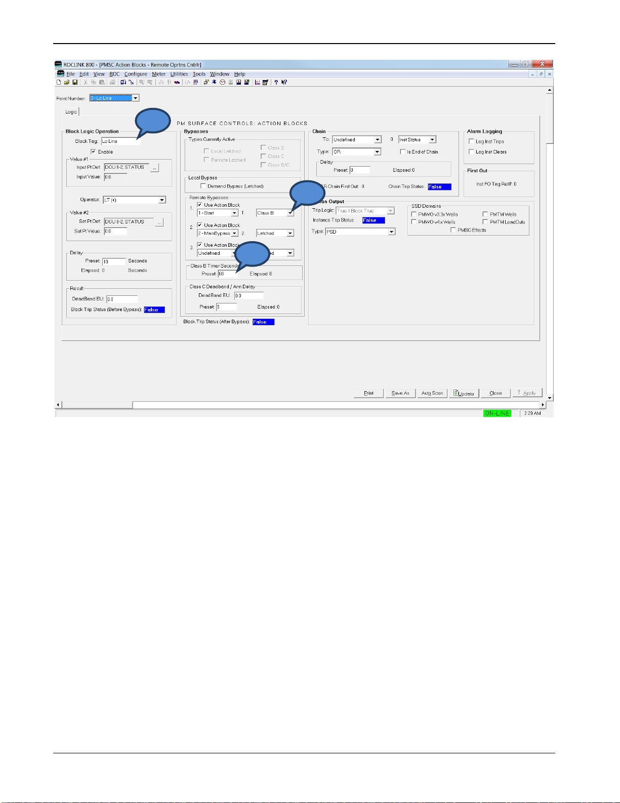
Surface Control Manager Program User Manual (ROC800-Series and FloBoss 107)
56 Configuration Revised January-2017
Figure 3-20. PMSC Action Blocks – Configuring Lo Line
To configure an action block that needs to be bypassed for a period of
time:
1. Browse for the action block that monitors the Start Action.
2. Select Class B as the Remote Bypass type.
3. Enter the amount of time to bypass this block in the Class B Timer
Seconds Preset once the Start Action is true.
1 3 2
Page 61

Surface Control Manager Program User Manual (ROC800-Series and FloBoss 107)
Revised January-2017 Configuration 57
3.5.5 Creating a Timed Maintenance Bypass
Figure 3-21. PMSC Action Blocks – Creating a Timed Maintenance Bypass
Configure an action block to monitor a softpoint value that is not
connected to real IO (such as softpoint byte field).
1. Use the Operator Soft Input Reset Timer.
2. Set the amount of time this block is true in the Delay Preset field
once the Input Value is true.
3. When the Delay Preset time expires, the block goes false.
1
Page 62

Surface Control Manager Program User Manual (ROC800-Series and FloBoss 107)
58 Configuration Revised January-2017
Figure 3-22. PMSC Action Blocks – Configuring Hi Line
To configure an action block needing a timed maintenance bypass:
1. Select the action block that monitors the Maintenance Bypass
function.
2. Select Latched for the Remote Bypass.
3. The block is bypassed as long as the MaintBypass action block
remains true.
1
2
Page 63

Surface Control Manager Program User Manual (ROC800-Series and FloBoss 107)
Revised January-2017 Reference 59
Chapter 4 – Reference
This section provides information of point types and parameters used by
the Surface Control Manager and Calculation Blocks program.
For Action Blocks
Point Type 68 (ROC800)
Point Type 28 (FB107)
For Utilities
Point Type 71 (ROC800)
Point Type 31 (FB107)
For Calculation Blocks
Point Type 218 (ROC800)
Point Type 27 (Slot #3) or Alternate #39 (Slot #6) (FB107)
Page 64

Surface Control Manager Program User Manual (ROC800-Series and FloBoss 107)
60 Reference Revised January-2017
4.1 Point Type 68/28: Action Blocks
Point type 68 (for ROC800) or point type 28 (for FB107) contains the parameters for configuring the action blocks. For the ROC800, the
program maintains 48, 96, 144 or 192 instances of this point type (based on the size of the installed program); for the FB107, the program
maintains 48 instances of the point type.
Point Type 68 (ROC800) or Point 28 (FB107): Action Blocks
Param
#
Name
Access
System or User
Update
Data
Type
Length
Range
Default
Version
Description of Functionality
and Meaning of Values
0
Block Tag
R/W
User
AC10
10
0x20 0x7E for
each ASCII
character
Block #”
(# =
logical
number)
4.03.05
Sets the tag name for action
block.
1
Enable
R/W
User
UINT8 1 0 - 1
0
4.03.05
Enables action block.
0 = Disabled
1 = Enabled
2
Input Pt Def
R/W
User
TLP
3
Any Valid IEEE
numeric TLP
0,0,0
4.03.05
Sets the TLP source of the
input value.
3
Input Value
R/O
System
FLOAT
4
Any floating point
number
0.0
4.03.05
Displays the input value from
the TLP.
4
Statement Operator
R/W
User
TLP 1 0 - 17
0,0,0
4.03.05
Selects a logical or
mathematical operator.
0 = GT (>)
1 = GE (>=)
2 = LT (<)
3 = LE (<=)
4 = EQ (==)
5 = NE (!=)
6 = Watchdog
7 = Trip On Change
8 = pEdge
9 = nEdge
10 = Bitwise AND (&)
11 = Bitwise OR
12 = Add (+)
13 = Subtract (-)
14 = Multiply (*)
15 = Divide (/)
16 = Modulus (%)
17 = Soft Input Reset Timer
5
Setpoint Def
R/W
User
FLOAT
3
Any Valid IEEE
numeric TLP
0.0
4.03.05
Selects the TLP source of the
Setpoint value.
Page 65

Surface Control Manager Program User Manual (ROC800-Series and FloBoss 107)
Revised January-2017 Reference 61
Point Type 68 (ROC800) or Point 28 (FB107): Action Blocks
Param
#
Name
Access
System or User
Update
Data
Type
Length
Range
Default
Version
Description of Functionality
and Meaning of Values
6
Setpoint Value
R/W
User
UINT16
4
Any floating
number
0
4.03.05
Displays live Set Pt Value from
TLP or user entered manual
value.
7
Delay Sec Preset
R/O
System
UINT16 2 0 - 65535
0
4.03.05
Sets the delay in seconds that
is either for an on delay for
logic functions or for soft input
rest timer.
8
Delay Sec Elapsed
R/W
User
FLOAT 2 0 - 65535
0.0
4.03.05
Shows the delay elapse time.
9
Action Db Result
R/O
System
UINT8 4 Any floating
number
0
4.03.05
Sets the Deadband for logic
operators or math result for
mathematical operators.
10
Refined Block Status
R/W
User
TLP 1 0 - 1
0,0,0
4.03.05
Shows the block trip status
after bypass.
0 = False
1 = True
11
Block Action Type
R/W
User
UINT8 1 0-6
0
4.03.05
Sets the Action Output type.
0 = PSD (Permanent
Shutdown)
1 = TSD (Temporary
Shutdown)
2 = DO (Binary Action)
3 = Move Value
4 = VAL (to Result Register)
5 = SAV (from Result Register)
6 = No Action
12
Block Action Item Pt Def
R/W
User
TLP
3
Any Valid IEEE
numeric TLP
0,0,0
4.03.05
Sets the action Item Pt Def TLP
selection, only visible with DO,
Move Value, VAL, and SAV.
13
Block DO Behavior
R/W
User
UINT8 1 0 - 9
0
4.03.05
Selects the Action Output DO
(Binary Action) behavior.
0 = Force 1True & 0False
1 = Force 0True & 1False
2 = Poke 1True
3 = Poke 0True
4 = Poke 1True & 0False
5 = Poke 0True & 1False
6 = Force 1True & Poke 0F
7 = Force 0True & Poke 1F
8 = Force 1True
9 = Force 0True
Page 66

Surface Control Manager Program User Manual (ROC800-Series and FloBoss 107)
62 Reference Revised January-2017
Point Type 68 (ROC800) or Point 28 (FB107): Action Blocks
Param
#
Name
Access
System or User
Update
Data
Type
Length
Range
Default
Version
Description of Functionality
and Meaning of Values
14
Raw Block Status
R/O
System
UINT8 1 0 - 1
0
4.03.05
Blocks trip status before
bypass.
0 = False
1 = True
15
Bypasses Active
R/O
System
UINT8 1 0 - 31
0
4.03.05
Shows the bypasses that are
currently active.
0 = None
Bit 0 = Local Latched
Bit 1 = Remote Latched
Bit 2 = Class B
Bit 3 = Class C
Bit 4 = Class B/C
16
Chain Status
R/O
System
UINT8 1 0-1
0
4.03.05
Chain trip status.
0 = False
1 = True
17
Trip Status
R/O
System
UINT8 1 0-1
0
4.03.05
Shows the instance trip status.
0 = False
1 = True
18
Chain With Inst
R/W
User
UINT8
1
0-# Logicals (48,
96, 144)
0
4.03.05
Sets a chain to a block
instance.
19
Chain With What Aspect
R/W
User
UINT8 1 0-2
2
4.03.05
Sets a status to chain to from
block instance.
0 = Block Status
1 = Chain Status (After Bypass)
2 = Inst Status
20
Chain Type
R/W
User
UINT8 1 0-8
1
4.03.05
Selects the Chain Type to
compare with chained block
instance and associated status.
0 = AND
1 = OR
2 = NAND
3 = XOR_EITHER
4 = XOR_LOCAL
5 = XOR_REMOTE
6 = SEAL-IN
7 = PWM LO-DUTY
8 = PWM HI-DUTY
21
Chain First Out
R/O
System
UINT8
1
0-# Logicals (48,
96, 144)
0
4.03.05
Shows OR chain first out
number, only visible with Chain
Type OR.
Page 67

Surface Control Manager Program User Manual (ROC800-Series and FloBoss 107)
Revised January-2017 Reference 63
Point Type 68 (ROC800) or Point 28 (FB107): Action Blocks
Param
#
Name
Access
System or User
Update
Data
Type
Length
Range
Default
Version
Description of Functionality
and Meaning of Values
22
SSD Destination
Domains
R/W
User
UINT8 1 0-31
0
4.03.05
Sets the SSD domains for
Action Output Type PSD or
TSD.
Bit 0 = PMTM Wells
Bit 1 = PMTM Loadouts
Bit 2 = PMWO Wells
Bit 3 = PMv3.3x Wells
Bit 4 = PMSC Effects
23
Is End of Chain
R/W
User
UINT8 1 0 - 1
0
4.03.05
Indicates the last block in a
chain.
0 = False
1 = True
24
Chain Delay Sec Preset
R/W
User
UINT16 2 0 - 65535
0
4.03.05
Sets the delay in seconds as
an on delay for the chain trip
status.
25
Chain Delay Sec
Elapsed
R/O
System
UINT16 2 0 - 65535
0
4.03.05
Shows the chain delay elapsed
time in seconds.
26
Apply Action Upon
R/W
User
UINT8 1 0 - 3
0
4.03.05
Sets the Action Output
Block/Chain Trip logic.
0 = True if Block True
1 = True if Chain True
2 = True if Either True
3 = True if Both True
27
1st Remote Bypass Inst
R/W
User
UINT8
1
0-# Logicals (48,
96, 144)
0
4.03.05
Remote Bypass 1 block
instance selection.
28
2nd Remote Bypass Inst
R/W
User
UINT8
1
0-# Logicals (48,
96, 144)
0
4.03.05
Remote Bypass 2 block
instance selection.
29
3rd Remote Bypass Inst
R/W
User
UINT8
1
0-# Logicals (48,
96, 144)
0
4.03.05
Remote Bypass 3 block
instance selection.
30
1st Remote Bypass Type
R/W
User
UINT8 1 0 - 3
0
4.03.05
Remote Bypass 1 bypass type.
0 = Latched
1 = Class B
2 = Class C
3 = Class B/C
31
2nd Remote Bypass
Type
R/W
User
UINT8 1 0 - 3
0
4.03.05
Remote Bypass 2 bypass type.
0 = Latched
1 = Class B
2 = Class C
3 = Class B/C
Page 68

Surface Control Manager Program User Manual (ROC800-Series and FloBoss 107)
64 Reference Revised January-2017
Point Type 68 (ROC800) or Point 28 (FB107): Action Blocks
Param
#
Name
Access
System or User
Update
Data
Type
Length
Range
Default
Version
Description of Functionality
and Meaning of Values
32
3rd Remote Bypass
Type
R/W
User
UINT8 1 0 - 3
0
4.03.05
Remote Bypass 3 bypass type.
0 = Latched
1 = Class B
2 = Class C
3 = Class B/C
33
Local Latched Bypass
R/W
User
UINT8 1 0 - 1
0
4.03.05
Enables or disables the Local
Bypass – Demand Bypass
(Latched), manual bypass.
0 = Disabled
1 = Enabled
34
Class C Byp Deadband
EU
R/W
User
FL
1
Any floating point
number
0.0
4.03.05
Sets the Deadband value for
Class C bypass.
35
Class B Timer Preset
Sec
R/W
User
UINT16 2 0 - 65535
300
4.03.05
Sets the Class B Preset timer
in seconds.
36
Class C Arm Delay Sec
R/W
User
UINT16 2 0 - 65535
5
4.03.05
Sets the Class C Arm Delay
Preset timer in seconds.
37
Class B Elap Sec
R/O
System
UINT16 2 0 - 65535
0
4.03.05
Shows the Class B timer
elapsed time in seconds.
38
Class C DB Arm Delay
Elap
R/O
System
UINT16 2 0 - 65535
0
4.03.05
Shows the Class C timer
elapsed time in seconds.
39
Is a Browseable Bypass
R/W
User
UINT8 1 0-1
0
4.03.05
Determines if block selected as
a bypass is a valid selection,
this parameter is not visible.
40
Log Instance Trips
R/W
User
UINT8 1 0 - 1
0
4.03.05
Enables or disables Alarm
Logging, log instance trips.
0 = No log
1 = Log Trips
41
Log Instance Clears
R/W
User
UINT8 1 0 - 1
0
4.03.05
Enables or disables Alarm
Logging, log instance clears.
0 = No log
1 = Log Clears
42
Inst FO Tag Ref
R/O
System
UINT8
1
0-# Logicals (48,
96, 144)
0
4.03.05
Sets the tag number of FO
tripped instance.
Page 69

Surface Control Manager Program User Manual (ROC800-Series and FloBoss 107)
Revised January-2017 Reference 65
Point Type 68 (ROC800) or Point 28 (FB107): Action Blocks
Param
#
Name
Access
System or User
Update
Data
Type
Length
Range
Default
Version
Description of Functionality
and Meaning of Values
43
SSD TM Well List 1-8
R/W
User
UINT8 1 0 - 255
0
4.03.05
Sets the SSD Domains link to
PMTM Wells 1-8.
Bit 0 = Well 1
Bit 1 = Well 2
Bit 2 = Well 3
Bit 3 = Well 4
Bit 4 = Well 5
Bit 5 = Well 6
Bit 6 = Well 7
Bit 7 = Well 8
44
SSD TM Well List 9-12
R/W
User
UINT8 1 0 - 15
0
4.03.05
Sets the SSD Domains link to
PMTM Wells 9-12.
Bit 0 = Well 9
Bit 1 = Well 10
Bit 2 = Well 11
Bit 3 = Well 12
45
SSD LoadOut List
R/W
User
UINT8 1 0 - 63
0
4.03.05
Sets the SSD Domains link to
PMTM LoadOuts 1-6.
Bit 0 = LoadOut 1
Bit 1 = LoadOut 2
Bit 2 = LoadOut 3
Bit 3 = LoadOut 4
Bit 4 = LoadOut 5
Bit 5 = LoadOut 6
46
SSD WO Well List 1-8
R/W
User
UINT8 1 0 - 255
0
4.03.05
Sets the SSD Domains link to
PMWO Wells 1-8.
Bit 0 = Well 1
Bit 1 = Well 2
Bit 2 = Well 3
Bit 3 = Well 4
Bit 4 = Well 5
Bit 5 = Well 6
Bit 6 = Well 7
Bit 7 = Well 8
47
SSD WO Well List 9-12
R/W
User
UINT8 1 0 - 15
0
4.03.05
Sets the SSD Domains link to
PMWO Wells 9-12.
Bit 0 = Well 9
Bit 1 = Well 10
Bit 2 = Well 11
Bit 3 = Well 12
Page 70

Surface Control Manager Program User Manual (ROC800-Series and FloBoss 107)
66 Reference Revised January-2017
Point Type 68 (ROC800) or Point 28 (FB107): Action Blocks
Param
#
Name
Access
System or User
Update
Data
Type
Length
Range
Default
Version
Description of Functionality
and Meaning of Values
48
SSD PM v3.30 Well List
1-6
R/W
User
UINT8 1 0 - 63
0
4.03.05
Sets the SSD Domains link to
PMv3.3x Wells 1-8.
Bit 0 = Well 1
Bit 1 = Well 2
Bit 2 = Well 3
Bit 3 = Well 4
Bit 4 = Well 5
Bit 5 = Well 6
49
SSD PMSC Effects 1-8
R/W
User
UINT8 1 0 - 255
0
4.03.05
SSD Domains link to PMSC
Effects 1-8.
Bit 0 = Effect 1
Bit 1 = Effect 2
Bit 2 = Effect 3
Bit 3 = Effect 4
Bit 4 = Effect 5
Bit 5 = Effect 6
Bit 6 = Effect 7
Bit 7 = Effect 8
50
SSD PMSC Effects 9-16
R/W
User
UINT8 1 0 - 255
0
4.03.05
Sets the SSD Domains link to
PMSC Effects 9-16.
Bit 0 = Effect 9
Bit 1 = Effect 10
Bit 2 = Effect 11
Bit 3 = Effect 12
Bit 4 = Effect 13
Bit 5 = Effect 14
Bit 6 = Effect 15
Bit 7 = Effect 16
51
SSD PMSC Effects 1724
R/W
User
UINT8 1 0 - 255
0
4.03.05
Sets the SSD Domains link to
PMSC Effects 17-24.
Bit 0 = Effect 17
Bit 1 = Effect 18
Bit 2 = Effect 19
Bit 3 = Effect 20
Bit 4 = Effect 21
Bit 5 = Effect 22
Bit 6 = Effect 23
Bit 7 = Effect 24
Page 71

Surface Control Manager Program User Manual (ROC800-Series and FloBoss 107)
Revised January-2017 Reference 67
Point Type 68 (ROC800) or Point 28 (FB107): Action Blocks
Param
#
Name
Access
System or User
Update
Data
Type
Length
Range
Default
Version
Description of Functionality
and Meaning of Values
52
SSD PMSC Effects
25-32
R/W
User
UINT8 1 0 - 255
0
4.03.05
Sets the SSD Domains link to
PMSC Effects 25-32.
Bit 0 = Effect 25
Bit 1 = Effect 26
Bit 2 = Effect 27
Bit 3 = Effect 28
Bit 4 = Effect 29
Bit 5 = Effect 30
Bit 6 = Effect 31
Bit 7 = Effect 32
53
SSD PMSC Effects
33-36
R/W
User
UINT8 1 0 - 15
0
4.03.05
Sets the SSD Domains link to
PMSC Effects 33-36.
Bit 0 = Effect 33
Bit 1 = Effect 34
Bit 2 = Effect 35
Bit 3 = Effect 36
54
Remote Bypass Status
R/O
System
UINT8 1 0
0
4.03.05
Shows the Trip status of
remote bypasses.
Bit 0 = Remote Bypass 1
Status
Bit 1 = Remote Bypass 2
Status
Bit 2 = Remote Bypass 3
Status
55
Prev Scan Trip Status
R/W
User
UINT8 1 0-1
0
4.03.05
The block status after bypass
of the previous, this parameter
is not displayed.
56
Bypass Location Type 1
R/W
User
UINT8 1 0-1
0
4.06.00
Determines if remote bypass 1
is activated by another action
block, or by a user selected
TLP.
0 = User Selected TLP
1 = Remote Action Block
57
Bypass Location Type 2
R/W
User
UINT8 1 0-1
0
4.06.00
Determines if remote bypass 2
is activated by another action
block, or by a user selected
TLP.
0 = User Selected TLP
1 = Remote Action Block
Page 72

Surface Control Manager Program User Manual (ROC800-Series and FloBoss 107)
68 Reference Revised January-2017
Point Type 68 (ROC800) or Point 28 (FB107): Action Blocks
Param
#
Name
Access
System or User
Update
Data
Type
Length
Range
Default
Version
Description of Functionality
and Meaning of Values
58
Bypass Location Type 3
R/W
User
UINT8 1 0-1
0
4.06.00
Determines if remote bypass 3
is activated by another action
block, or by a user selected
TLP.
0 = User Selected TLP
1 = Remote Action Block
59
Remote Bypass TLP
Def 1
R/W
User
TLP
3
Any Valid Numeric
TLP
0,0,0
4.06.00
Sets the TLP source for remote
bypass 1, if the type is set to
use a TLP definition.
60
Remote Bypass TLP
Def 2
R/W
User
TLP
3
Any Valid Numeric
TLP
0,0,0
4.06.00
Sets the TLP source for remote
bypass 2, if the type is set to
use a TLP definition.
61
Remote Bypass TLP
Def 3
R/W
User
TLP
3
Any Valid Numeric
TLP
0,0,0
4.06.00
Sets the TLP source for remote
bypass 3, if the type is set to
use a TLP definition.
62
SSD PMSC Effects
41-48
R/W
User
UINT8 1 0 - 255
0
4.06.00
Sets the SSD Domains link to
PMSC Effects 41-48.
Bit 0 = Effect 41
Bit 1 = Effect 42
Bit 2 = Effect 43
Bit 3 = Effect 44
Bit 4 = Effect 45
Bit 5 = Effect 46
Bit 6 = Effect 47
Bit 7 = Effect 48
63
SSD PMSC Effects
49-56
R/W
User
UINT8 1 0 - 255
0
4.06.00
Sets the SSD Domains link to
PMSC Effects 49-56.
Bit 0 = Effect 49
Bit 1 = Effect 50
Bit 2 = Effect 51
Bit 3 = Effect 52
Bit 4 = Effect 53
Bit 5 = Effect 54
Bit 6 = Effect 55
Bit 7 = Effect 56
Page 73

Surface Control Manager Program User Manual (ROC800-Series and FloBoss 107)
Revised January-2017 Reference 69
Point Type 68 (ROC800) or Point 28 (FB107): Action Blocks
Param
#
Name
Access
System or User
Update
Data
Type
Length
Range
Default
Version
Description of Functionality
and Meaning of Values
64
SSD PMSC Effects
57-64
R/W
User
UINT8 1 0 - 255
0
4.06.00
Sets the SSD Domains link to
PMSC Effects 57-64.
Bit 0 = Effect 57
Bit 1 = Effect 58
Bit 2 = Effect 59
Bit 3 = Effect 60
Bit 4 = Effect 61
Bit 5 = Effect 62
Bit 6 = Effect 63
Bit 7 = Effect 64
Page 74

Surface Control Manager Program User Manual (ROC800-Series and FloBoss 107)
70 Reference Revised January-2017
4.2 Point Type 71/31: Utilities
Point type 71 (for ROC800) or point type 31 (for FB107) contains the parameters for configuring the utilities. For the ROC800, the program
maintains 12, 24, or 36 instances of this point type (depending on the size of the installed program); for the FB107, the program maintains 16
instances of this point type.
Point Type 71 (ROC800) or Point Type 31 (FB107): Utilities
Param
#
Name
Access
System or User
Update
Data
Type
Length
Range
Default
Version
Description of Functionality
and Meaning of Values
0
Instance Tag
R/W
User
AC10
10
0x20 0x7E for
each ASCII
character
Inst #
4.03.05
Sets the tag name for utilities.
1
Run Time Enable
R/W
User
UINT8 1 0 - 1
0
4.03.05
Enables time count.
0 = Disabled
1 = Enabled
2
Run Time Pt Def
R/W
User
TLP 3 Any Valid IEEE
numeric TLP
0,0,0
4.03.05
Sets the Run-Time Pt Def TLP
selection.
3
RT Operator
R/W
User
UINT8 1 0 - 5
0
4.03.05
Sets the logical operator for
run-time comparison.
0 = GT (>)
1 = GE (>=)
2 = LT (<)
3 = LE (<=)
4 = EQ (==)
5 = NE (!=)
4
RT Setpoint
R/W
User
FL
4
Any floating point
number
0.0
4.03.05
Sets the setpoint value.
5
RT Clear Now
R/W
User
UINT8 1 0 - 1
0
4.03.05
Clears all run-time
accumulators.
0 = Normal
1 = Clear Accums
6
RT Status
R/O
System
UINT8 1 0 - 1
0
4.03.05
Shows the status of live run-
time.
0 = False
1 = True
7
RT ON Mins Tdy
R/O
System
FL
4
Any positive floating
point number
0.0
4.03.05
Shows the Run-time ON
minutes today.
8
RT ON Mins Ydy
R/O
System
FL
4
Any positive floating
point number
0.0
4.03.05
Shows the Run-time ON
minutes yesterday.
9
RT ON Mins TMonth
R/O
System
FL
4
Any positive floating
point number
0.0
4.03.05
Shows the Run-time ON
minutes this month.
Page 75

Surface Control Manager Program User Manual (ROC800-Series and FloBoss 107)
Revised January-2017 Reference 71
Point Type 71 (ROC800) or Point Type 31 (FB107): Utilities
Param
#
Name
Access
System or User
Update
Data
Type
Length
Range
Default
Version
Description of Functionality
and Meaning of Values
10
RT ON Mins PMonth
R/O
System
FL
4
Any positive floating
point number
0.0
4.03.05
Shows the Run-time ON
minutes previous month.
11
RT ON Hours Tdy
R/O
System
FL
4
Any positive floating
point number
0.0
4.03.05
Shows the Run-time ON hours
today.
12
RT ON Hours Ydy
R/O
System
FL
4
Any positive floating
point number
0.0
4.03.05
Shows the Run-time ON hours
yesterday.
13
RT ON Hours TMonth
R/O
System
FL
4
Any positive floating
point number
0.0
4.03.05
Shows the Run-time ON hours
this month.
14
RT ON Hours PMonth
R/O
System
FL
4
Any positive floating
point number
0.0
4.03.05
Shows the Run-time ON hours
previous month.
15
RT ON Pct Tdy
R/O
System
FL
4
Any positive floating
point number
0.0
4.03.05
Shows the Run-time ON
percent today.
16
RT ON Pct Ydy
R/O
System
FL
4
Any positive floating
point number
0.0
4.03.05
Shows the Run-time ON
percent yesterday.
17
RT ON Pct Ydy
R/O
System
FL
4
Any positive floating
point number
0.0
4.03.05
Shows the Run-time ON
percent month.
18
RT ON Pct PMonth
R/O
System
FL
4
Any positive floating
point number
0.0
4.03.05
Shows the Run-time ON
percent previous month.
19
RT OFF Mins Tdy
R/O
System
FL
4
Any positive floating
point number
0.0
4.03.05
Shows the Run-time OFF
minutes today.
20
RT OFF Mins Ydy
R/O
System
FL
4
Any positive floating
point number
0.0
4.03.05
Shows the Run-time OFF
minutes yesterday.
21
RT OFF Mins TMonth
R/O
System
FL
4
Any positive floating
point number
0.0
4.03.05
Shows the Run-time OFF
minutes this month.
22
RT OFF Mins PMonth
R/O
System
FL
4
Any positive floating
point number
0.0
4.03.05
Shows the Run-time OFF
minutes previous month.
23
RT OFF Hours Tdy
R/O
System
FL
4
Any positive floating
point number
0.0
4.03.05
Shows the Run-time OFF hours
today.
24
RT OFF Hours Ydy
R/O
System
FL
4
Any positive floating
point number
0.0
4.03.05
Shows the Run-time OFF hours
yesterday.
25
RT OFF Hours TMonth
R/O
System
FL
4
Any positive floating
point number
0.0
4.03.05
Shows the Run-time OFF hours
this month.
26
RT OFF Hours PMonth
R/O
System
FL
4
Any positive floating
point number
0.0
4.03.05
Shows the Run-time OFF hours
previous month.
27
RT OFF Pct Tdy
R/O
System
FL
4
Any positive floating
point number
0.0
4.03.05
Shows the Run-time OFF
percent today.
28
RT OFF Pct Ydy
R/O
System
FL
4
Any positive floating
point number
0.0
4.03.05
Shows the Run-time OFF
percent yesterday.
Page 76

Surface Control Manager Program User Manual (ROC800-Series and FloBoss 107)
72 Reference Revised January-2017
Point Type 71 (ROC800) or Point Type 31 (FB107): Utilities
Param
#
Name
Access
System or User
Update
Data
Type
Length
Range
Default
Version
Description of Functionality
and Meaning of Values
29
RT OFF Pct TMonth
R/O
System
FL
4
Any positive floating
point number
0.0
4.03.05
Shows the Run-time OFF
percent month.
30
RT OFF Pct PMonth
R/O
System
FL
4
Any positive floating
point number
0.0
4.03.05
Shows the Run-time OFF
percent previous month.
31
Contract Hour
R/W
User
UINT8 1 0 - 23
0
4.03.05
Sets the number of hours when
transition occurs between days.
32
Cur Day in Use
R/O
System
UINT8 1 1 - 31
Day
4.03.05
Shows the Current day of the
month.
33
Cur Month in Use
R/O
System
UINT8 1 1 - 12
Month
4.03.05
Shows the Current month.
34
Accum / Prop Out
Mode
R/W
User
UINT8 1 0 - 3
0
4.03.05
Selects the Accum/Prop Output
Mode.
0 = Accumulate a Rate
1 = Accumulate a Running
Total
2 = Output a 4-20ma Signal
3 = Generate a Pulse at an
Interval
35
AC/PO Enable
R/W
User
UINT8 1 0 - 1
0
4.03.05
Enables accumulator /
proportional output.
0 = Disabled
1 = Enabled
36
AC/PO Input Def
R/W
User
TLP 3 Any Valid IEEE
numeric TLP
0,0,0
4.03.05
Sets the TLP source for Input
Value.
37
AC/PO Output Def
R/W
User
TLP 3 Any Valid IEEE
numeric TLP
0,0,0
4.03.05
Sets the TLP source for Output
Value.
38
AC/PO Time Basis
R/W
User
UINT8 1 0 - 3
3
4.03.05
Sets the Time basis for
Accum/Prop Output.
0 = Per Day
1 = Per Hour
2 = Per Minute
3 = Per Second
39
Prop Out Pulse Interval
R/W
User
FL
4
Any floating point
number
1000.0
4.03.05
Sets the DO Output Pulse
Interval to send out a pulse,
only visible when Mode is set to
Generate a Pulse at an
Interval.
Page 77

Surface Control Manager Program User Manual (ROC800-Series and FloBoss 107)
Revised January-2017 Reference 73
Point Type 71 (ROC800) or Point Type 31 (FB107): Utilities
Param
#
Name
Access
System or User
Update
Data
Type
Length
Range
Default
Version
Description of Functionality
and Meaning of Values
40
Prop Out Interval
Accum
R/W
User
FL
4
Any positive floating
point number
0.0
4.03.05
Sets the Current Interval
Accumulation. This is only
visible when Mode is set to
Generate a Pulse at an
Interval.
41
PMSC Effect Enable
R/W
User
UINT8 1 0 - 1
0,0,0
4.03.05
Enables Effect.
0 = Disabled
1 = Enabled
42
PMSC Effect Def
R/W
User
TLP 3 Any Valid IEEE
numeric TLP
0
4.03.05
Selects the Effect Output Pt
Def TLP selection.
43
Effect Trip Status
R/W
User
UINT8 1 0 - 1
1.0
4.03.05
Enables the Effect Trip Status.
0 = Inactive
1 = Active
44
Effect Cur Output
Value
R/W
User
FL
4
Any floating point
number
0.0
4.03.05
Effect Output Current Value
45
Value When Tripped
R/W
User
FL
4
Any floating point
number
1.0
4.03.05
Value when Effect is active.
46
Value When Not
Tripped
R/W
User
FL
4
Any floating point
number
1
4.03.05
Value when Effect is inactive.
47
Apply When Not
Tripped
R/W
User
UINT8 1 0 - 1
1
4.03.05
Output the Value When Not
Tripped.
0 = Disabled
1 = Enabled
48
Assert Output
Continuously
R/W
User
UINT8 1 0 - 3
4.03.05
Asserts Output Continuously
During selected state.
0 = Neither State
1 = Tripped State Only
2 = UnTripped State Only
3 = Both States
49
Effect Requires Preset
R/W
User
UINT8 1 0 - 1
0
4.03.05
Enables Reset for tripped
Effect.
0 = Disabled
1 = Enabled
50
1st Out PMSC Block
R/W
User
UINT8 1 0-# Logicals
(48, 96, 144)
0
4.03.05
Sets the Instance number of
first tripped action block.
Page 78

Surface Control Manager Program User Manual (ROC800-Series and FloBoss 107)
74 Reference Revised January-2017
Point Type 71 (ROC800) or Point Type 31 (FB107): Utilities
Param
#
Name
Access
System or User
Update
Data
Type
Length
Range
Default
Version
Description of Functionality
and Meaning of Values
51
Ready For Reset
R/W
User
UINT8 1 0 - 1
0
4.03.05
Shows the status that effect is
ready to be reset for a PSD
action block trip that has
cleared, only visible when Trips
Require Reset is checked and
eEffect is ready to be reset.
52
Remote Reset TLP
R/W
User
TLP 3 Any Valid IEEE
numeric TLP
0,0,0
4.03.05
Activates the Remote Reset
Command TLP selection.
53
Reset Status
R/W
User
UINT8 1 0-255
0
4.03.05
The reset command that holds
the value that must be entered
to reset a trip in a PSD
condition.
54
Prev Effect State
R/W
User
UINT8 1 0-2
0
4.03.05
Shows the previous state of the
effect.
0 = Inactive
1 = Active, not ready for reset
2 = Active, ready for reset
55
Write Update Period
R/W
User
UINT8 1 0 - 60
0
4.03.05
Sets the Update Interval for
Time Count.
1 = 1 Second
2 = 2 Seconds
3 = 3 Seconds
4 = 4 Seconds
5 = 5 Seconds
6 = 6 Seconds
10 = 10 Seconds
12 = 12 Seconds
15 = 15 Seconds
20 = 20 Seconds
30 = 30 Seconds
60 = 60 Seconds
56
AC/PO Flags
R/W
User
UINT8 1 0 - 4
0
4.03.05
Selects the flag for Accum/Prop
Outputs. This is only visible
when mode is set to
Accumulate a Rate or
Accumulate a Running Total.
0 = Normal Operation.
1 = Force End of Day
2 = Force End of Month
3 = Flush Running Accum
4 = Cold Start Accumulator Set
Page 79

Surface Control Manager Program User Manual (ROC800-Series and FloBoss 107)
Revised January-2017 Reference 75
Point Type 71 (ROC800) or Point Type 31 (FB107): Utilities
Param
#
Name
Access
System or User
Update
Data
Type
Length
Range
Default
Version
Description of Functionality
and Meaning of Values
57
Effect First Out Tag
R/O
System
AC10
10
0x20 0x7E for
each ASCII
character
<clear>
4.03.05
Shows the tag of first tripped
action block.
58
Perm Shutdown Set
R/W
User
UINT8 1 0 - 31
0
4.03.05
Sets the status of PSD trips.
Bit 0 = Tank Mgr Well #1
Bit 1 = Tank Mgr LoadOut #1
Bit 2 = Well Opt Mgr Well #1
Bit 3 = PMv3.3 Well #1
Bit 4 = PMSC Effect #1
59
Temp Shutdown Set
R/W
User
UINT8 1 0 - 31
0
4.03.05
Sets the status of TSD trips.
Bit 0 = Tank Mgr Well #1
Bit 1 = Tank Mgr LoadOut #1
Bit 2 = Well Opt Mgr Well #1
Bit 3 = PMv3.3 Well #1
Bit 4 = PMSC Effect #1
60
Any SSD Set
R/W
User
UINT8 1 0 - 31
0
4.03.05
Sets the status of any SSD
tripped.
Bit 0 = Tank Mgr Well #1
Bit 1 = Tank Mgr LoadOut #1
Bit 2 = Well Opt Mgr Well #1
Bit 3 = PMv3.3 Well #1
Bit 4 = PMSC Effect #1
61
Trip Code TM Well
R/W
User
UINT8 1 0 - 254
0
4.03.05
Sets the Trip Code for PMTM
Well reset.
62
Trip Code TM LoadOut
R/W
User
UINT8 1 0 - 254
0
4.03.05
Sets the Trip Code for PMTM
LoadOut reset.
63
Trip Code WO Well
R/W
User
UINT8 1 0 - 254
0
4.03.05
Sets the Trip Code for PMWO
Well reset.
64
Trip Code PMv3 Well
R/W
User
UINT8 1 0 - 254
0
4.03.05
Sets the Trip Code for PMv3.3
Well reset.
65
Trip Code PMSC
Effects
R/W
User
UINT8 1 0 - 254
0
4.03.05
Sets the Trip Code for PMSC
Effect reset.
66
Max Logicals
R/W
User
UINT8 1 48,96,144
48
4.03.05
Sets the maximum number of
logical, depending on PMSC
version.
67
User Prog Watchdog
Timer
R/W
User
UINT16 2 0-65535
0
4.03.05
Used to verify that program is
still running, time counter that
increments once per second.
Page 80

Surface Control Manager Program User Manual (ROC800-Series and FloBoss 107)
76 Reference Revised January-2017
Point Type 71 (ROC800) or Point Type 31 (FB107): Utilities
Param
#
Name
Access
System or User
Update
Data
Type
Length
Range
Default
Version
Description of Functionality
and Meaning of Values
68
Alarm Pt Tag 1
R/W
User
AC10
10
0x20 0x7E for
each ASCII
character
“Alarm 1”
4.06.00
Sets the tag for the Alarm Point
1.
69
Alarm Pt Indef TLP 1
R/W
User
TLP
3
Any Valid Numeric
TLP
0,0,0
4.06.00
Sets the TLP source for the
variable to be monitored for the
alarm block instance.
71
Alarm Pt Input Val 1
R/W
User
FL 4 Any Valid IEEE
Floating Point
Number
0
4.06.00
The current value of the input
parameter for the alarm block.
72
Alarm Pt Mode Val 1
R/W
User
UINT8 1 0 - 255
0
4.06.00
Defines the actions for the
alarm block.
Bit 0 = Boolean Alarm – Set on
0 / Set on 1
Bit 1 = Alarm Type – Analog /
Boolean
Bit 2 = Not Used
Bit 3 = Not Used
Bit 4 = Alarm Enable – Disable
/ Enable
Bit 5 = SRBX on Clear
Bit 6 = SRBX on Set
Bit 7 = Scanning – Disable /
Enable
73
Alarm Pt Code Val 1
R/W
User
UINT8 1 0 - 255
0
4.06.00
Provides an indication of all
active alarms.
Bit 0 = Low Alarm
Bit 1 = Low Low Alarm
Bit 2 = High Alarm
Bit 3 = High High Alarm
Bit 4 = Not Used
Bit 5 = Boolean
Bit 6 = Not Used
Bit 7 = Scanning Disabled
74
Alarm Pt Low Val 1
R/W
User
FL 4 Any Valid IEEE
Floating Point
Number
-10.0
4.06.00
Value for a Low Alarm in
engineering units.
75
Alarm Pt Low Low Val
1
R/W
User
FL 4 Any Valid IEEE
Floating Point
Number
-20.0
4.06.00
Value for a Low Low Alarm in
engineering units.
Page 81

Surface Control Manager Program User Manual (ROC800-Series and FloBoss 107)
Revised January-2017 Reference 77
Point Type 71 (ROC800) or Point Type 31 (FB107): Utilities
Param
#
Name
Access
System or User
Update
Data
Type
Length
Range
Default
Version
Description of Functionality
and Meaning of Values
76
Alarm Pt High Val 1
R/W
User
FL 4 Any Valid IEEE
Floating Point
Number
110.0
4.06.00
Value for a High Alarm in
engineering units.
77
Alarm Pt High High Val
1
R/W
User
FL 4 Any Valid IEEE
Floating Point
Number
120.0
4.06.00
Value for a High High Alarm in
engineering units.
78
Alarm Pt Deadband Val
1
R/W
User
FL 4 Any Valid IEEE
Floating Point
Number
10.0
4.06.00
Provides a range (+/-) that the
live input value may move
between without causing
another alarm.
79
Alarm Pt Tag 2
R/W
User
AC10
10
0x20 0x7E for
each ASCII
character
“Alarm 2”
4.06.00
Sets the tag for the Alarm Point
2.
80
Alarm Pt Indef TLP 2
R/W
User
TLP
3
Any Valid Numeric
TLP
0,0,0
4.06.00
Sets the TLP source for the
variable to be monitored for the
alarm block instance.
81
Alarm Pt Input Val 2
R/W
User
FL 4 Any Valid IEEE
Floating Point
Number
0
4.06.00
The current value of the input
parameter for the alarm block.
82
Alarm Pt Mode Val 2
R/W
User
UINT8 1 0 - 255
0
4.06.00
Defines the actions for the
alarm block.
Bit 0 = Boolean Alarm – Set on
0 / Set on 1
Bit 1 = Alarm Type – Analog /
Boolean
Bit 2 = Not Used
Bit 3 = Not Used
Bit 4 = Alarm Enable – Disable
/ Enable
Bit 5 = SRBX on Clear
Bit 6 = SRBX on Set
Bit 7 = Scanning – Disable /
Enable
Page 82

Surface Control Manager Program User Manual (ROC800-Series and FloBoss 107)
78 Reference Revised January-2017
Point Type 71 (ROC800) or Point Type 31 (FB107): Utilities
Param
#
Name
Access
System or User
Update
Data
Type
Length
Range
Default
Version
Description of Functionality
and Meaning of Values
83
Alarm Pt Code Val 2
R/W
User
UINT8 1 0 - 255
0
4.06.00
Provides an indication of all
active alarms.
Bit 0 = Low Alarm
Bit 1 = Low Low Alarm
Bit 2 = High Alarm
Bit 3 = High High Alarm
Bit 4 = Not Used
Bit 5 = Boolean
Bit 6 = Not Used
Bit 7 = Scanning Disabled
84
Alarm Pt Low Val 2
R/W
User
FL 4 Any Valid IEEE
Floating Point
Number
-10.0
4.06.00
Value for a Low Alarm in
engineering units.
85
Alarm Pt Low Low Val
2
R/W
User
FL 4 Any Valid IEEE
Floating Point
Number
-20.0
4.06.00
Value for a Low Low Alarm in
engineering units.
86
Alarm Pt High Val 2
R/W
User
FL 4 Any Valid IEEE
Floating Point
Number
110.0
4.06.00
Value for a High Alarm in
engineering units.
87
Alarm Pt High High Val
2
R/W
User
FL 4 Any Valid IEEE
Floating Point
Number
120.0
4.06.00
Value for a High High Alarm in
engineering units.
88
Alarm Pt Deadband Val
2
R/W
User
FL 4 Any Valid IEEE
Floating Point
Number
10.0
4.06.00
Provides a range (+/-) that the
live input value may move
between without causing
another alarm.
89
Alarm Pt Tag 3
R/W
User
AC10
10
0x20 0x7E for
each ASCII
character
“Alarm 3”
4.06.00
Sets the tag for the Alarm Point
3.
90
Alarm Pt Indef TLP 3
R/W
User
TLP
3
Any Valid Numeric
TLP
0,0,0
4.06.00
Sets the TLP source for the
variable to be monitored for the
alarm block instance.
91
Alarm Pt Input Val 3
R/W
User
FL 4 Any Valid IEEE
Floating Point
Number
0
4.06.00
The current value of the input
parameter for the alarm block.
Page 83

Surface Control Manager Program User Manual (ROC800-Series and FloBoss 107)
Revised January-2017 Reference 79
Point Type 71 (ROC800) or Point Type 31 (FB107): Utilities
Param
#
Name
Access
System or User
Update
Data
Type
Length
Range
Default
Version
Description of Functionality
and Meaning of Values
92
Alarm Pt Mode Val 3
R/W
User
UINT8 1 0 - 255
0
4.06.00
Defines the actions for the
alarm block.
Bit 0 = Boolean Alarm – Set on
0 / Set on 1
Bit 1 = Alarm Type – Analog /
Boolean
Bit 2 = Not Used
Bit 3 = Not Used
Bit 4 = Alarm Enable – Disable
/ Enable
Bit 5 = SRBX on Clear
Bit 6 = SRBX on Set
Bit 7 = Scanning – Disable /
Enable
93
Alarm Pt Code Val 3
R/W
User
UINT8 1 0 - 255
0
4.06.00
Provides an indication of all
active alarms.
Bit 0 = Low Alarm
Bit 1 = Low Low Alarm
Bit 2 = High Alarm
Bit 3 = High High Alarm
Bit 4 = Not Used
Bit 5 = Boolean
Bit 6 = Not Used
Bit 7 = Scanning Disabled
94
Alarm Pt Low Val 3
R/W
User
FL 4 Any Valid IEEE
Floating Point
Number
-10.0
4.06.00
Value for a Low Alarm in
engineering units.
95
Alarm Pt Low Low Val
3
R/W
User
FL 4 Any Valid IEEE
Floating Point
Number
-20.0
4.06.00
Value for a Low Low Alarm in
engineering units.
96
Alarm Pt High Val 3
R/W
User
FL 4 Any Valid IEEE
Floating Point
Number
110.0
4.06.00
Value for a High Alarm in
engineering units.
97
Alarm Pt High High Val
3
R/W
User
FL 4 Any Valid IEEE
Floating Point
Number
120.0
4.06.00
Value for a High High Alarm in
engineering units.
98
Alarm Pt Deadband Val
3
R/W
User
FL 4 Any Valid IEEE
Floating Point
Number
10.0
4.06.00
Provides a range (+/-) that the
live input value may move
between without causing
another alarm.
Page 84

Surface Control Manager Program User Manual (ROC800-Series and FloBoss 107)
80 Reference Revised January-2017
Point Type 71 (ROC800) or Point Type 31 (FB107): Utilities
Param
#
Name
Access
System or User
Update
Data
Type
Length
Range
Default
Version
Description of Functionality
and Meaning of Values
99
Time Counter Tag
R/W
User
AC10
10
0x20 0x7E for
each ASCII
character
“Time Cnt
1”
4.06.00
Sets the tag for the time
counter instance.
100
Max Accum Inter-Scan
R/W
User
FL 4 Any Valid IEEE
Floating Point
Number
100.0
4.06.00
Maximum accepted inter-scan
accumulation difference in
engineering units.
Page 85

Surface Control Manager Program User Manual (ROC800-Series and FloBoss 107)
Revised January-2017 Reference 81
4.3 Point Type 218: Calculation Blocks (for ROC800)
Point type 218 contains the parameters for the configuration of the PM Calculation Blocks of the program. The program maintains 4, 8, 12 or
16 instances of this point type (based on the size of the installed program).
Point Type 218 (for ROC800): Calculation Blocks
Param
#
Name
Access
System or User
Update
Data
Type
Length
Range
Default
Version
Description of Functionality
and Meaning of Values
0
Calculation Block X
R/W
User
String20
20
Printable ASCII
Characters
Calc
Block X
4.07.00
Tag for the Calculation block
1
Calculation Enable
R/W
User
UINT8 01
0
4.07.00
Solve Calculations for X, Y, and
Z
0 = NO
1 = YES
2
Input Description A
R/W
User
String10
10
Printable ASCII
Characters
<blank>
4.07.00
Description of Input A
3
Input Description B
R/W
User
String10
10
Printable ASCII
Characters
<blank>
4.07.00
Description of Input B
4
Input Description C
R/W
User
String10
10
Printable ASCII
Characters
<blank>
4.07.00
Description of Input C
5
Input Description D
R/W
User
String10
10
Printable ASCII
Characters
<blank>
4.07.00
Description of Input D
6
Input TLP A
R/W
User
TLP 3 Any TLP of a
Numeric Field
Undefined
4.07.00
Starting Location of Input A
7
Input TLP B
R/W
User
TLP 3 Any TLP of a
Numeric Field
Undefined
4.07.00
Starting Location of Input B
8
Input TLP C
R/W
User
TLP 3 Any TLP of a
Numeric Field
Undefined
4.07.00
Starting Location of Input C
9
Input TLP D
R/W
User
TLP 3 Any TLP of a
Numeric Field
Undefined
4.07.00
Starting Location of Input D
10
Input Value A
R/W
Both
Double
8
Any Double-Float
Value
0.0
4.07.00
Value of Input A (when array
size = 1)
11
Input Value B
R/W
Both
Double
8
Any Double-Float
Value
0.0
4.07.00
Value of Input B (when array
size = 1)
12
Input Value C
R/W
Both
Double
8
Any Double-Float
Value
0.0
4.07.00
Value of Input C (when array
size = 1)
13
Input Value D
R/W
Both
Double
8
Any Double-Float
Value
0.0
4.07.00
Value of Input D (when array
size = 1)
Page 86

Surface Control Manager Program User Manual (ROC800-Series and FloBoss 107)
82 Reference Revised January-2017
Point Type 218 (for ROC800): Calculation Blocks
Param
#
Name
Access
System or User
Update
Data
Type
Length
Range
Default
Version
Description of Functionality
and Meaning of Values
14
Calculation String X
R/W
User
String40
40
All Numbers, A-D,
X-Z, letters in
function names,
parenthesis, math
operators
<blank>
4.07.00
Free-Form calculation including
variables, operators and
functions
15
Calculation String Y
R/W
User
String40
40
All Numbers, A-D,
X-Z, letters in
function names,
parenthesis, math
operators
<blank>
4.07.00
Free-Form calculation including
variables, operators and
functions
16
Calculation String Z
R/W
User
String40
40
All Numbers, A-D,
X-Z, letters in
function names,
parenthesis, math
operators
<blank>
4.07.00
Free-Form calculation including
variables, operators and
functions
17
Calculation Valid X
R/W
System
UINT8 1 01
0
4.07.00
Is Calculation string X valid?
0 = NO
1 = YES
18
Calculation Valid Y
R/W
System
UINT8 1 01
0
4.07.00
Is Calculation string Y valid?
0 = NO
1 = YES
19
Calculation Valid Z
R/W
System
UINT8 1 01
0
4.07.00
Is Calculation string Z valid?
0 = NO
1 = YES
20
Calc Error Char NumX
R/W
System
UINT8 1 040
0
4.07.00
X Error Located at Char
Number
21
Calc Error Char NumY
R/W
System
UINT8 1 040
0
4.07.00
Y Error Located at Char
Number
22
Calc Error Char NumZ
R/W
System
UINT8 1 040
0
4.07.00
Z Error Located at Char
Number
23
Result Description X
R/W
User
String10
10
Printable ASCII
Characters
<blank>
4.07.00
Description of Result X
24
Result Description Y
R/W
User
String10
10
Printable ASCII
Characters
<blank>
4.07.00
Description of Result Y
25
Result Description Z
R/W
User
String10
10
Printable ASCII
Characters
<blank>
4.07.00
Description of Result Z
26
Result Value X
R/O
System
Double
8
Any Double-Float
Value
0.0
4.07.00
Value of Result X
Page 87

Surface Control Manager Program User Manual (ROC800-Series and FloBoss 107)
Revised January-2017 Reference 83
Point Type 218 (for ROC800): Calculation Blocks
Param
#
Name
Access
System or User
Update
Data
Type
Length
Range
Default
Version
Description of Functionality
and Meaning of Values
27
Result Value Y
R/O
System
Double
8
Any Double-Float
Value
0.0
4.07.00
Value of Result Y
28
Result Value Z
R/O
System
Double
8
Any Double-Float
Value
0.0
4.07.00
Value of Result Z
29
TLP Forwarding X
R/W
User
TLP 3 Any TLP of a
Numeric Field
Undefined
4.07.00
Forwarding Location for Result
X
30
TLP Forwarding Y
R/W
User
TLP 3 Any TLP of a
Numeric Field
Undefined
4.07.00
Forwarding Location for Result
Y
31
TLP Forwarding Z
R/W
User
TLP 3 Any TLP of a
Numeric Field
Undefined
4.07.00
Forwarding Location for Result
Z
32
Input Array Qty A
R/W
User
UINT8 1 110
1
4.07.00
Quantity of Values in Input A
33
Input Array Qty B
R/W
User
UINT8 1 110
1
4.07.00
Quantity of Values in Input B
34
Input Array Qty C
R/W
User
UINT8 1 110
1
4.07.00
Quantity of Values in Input C
35
Input Array Qty D
R/W
User
UINT8 1 110
1
4.07.00
Quantity of Values in Input D
36
Max Logicals
R/O
System
UINT8 1 4, 8, 12, 16
4, 8, 12,
16
4.07.00
Number of Calculation
Instances
37
UProg Watchdog Timer
R/O
System
UINT16 2 065535
0
4.07.00
Continually Changing Values
Page 88

Surface Control Manager Program User Manual (ROC800-Series and FloBoss 107)
84 Reference Revised January-2017
4.4 Point Type 27/39: Calculation Blocks (for FB107)
Point type 27 (Slot #3)/Alternate #39 (Slot #6) contains the parameters for the configuration of the PM Calculation Blocks of the program.
The program supports 4 logicals of point type 27 or 39.
Point Type 27/39 (for FB107): Calculation Blocks
Param
#
Name
Access
System or User
Update
Data
Type
Length
Range
Default
Version
Description of Functionality
and Meaning of Values
0
Calculation Tag
R/W
User
String20
20
Printable ASCII
Characters
Calc
Block X
4.00.01
Tag for the Calculation block
1
Calculation Enable
R/W
User
UINT8 01
0
4.00.01
Solve Calculations for X, Y, and
Z
0 = NO
1 = YES
2
Input Description A
R/W
User
String10
10
Printable ASCII
Characters
<blank>
4.00.01
Description of Input A
3
Input Description B
R/W
User
String10
10
Printable ASCII
Characters
<blank>
4.00.01
Description of Input B
4
Input Description C
R/W
User
String10
10
Printable ASCII
Characters
<blank>
4.00.01
Description of Input C
5
Input Description D
R/W
User
String10
10
Printable ASCII
Characters
<blank>
4.00.01
Description of Input D
6
Input TLP A
R/W
User
TLP 3 Any TLP of a
Numeric Field
Undefined
4.00.01
Starting Location of Input A
7
Input TLP B
R/W
User
TLP 3 Any TLP of a
Numeric Field
Undefined
4.00.01
Starting Location of Input B
8
Input TLP C
R/W
User
TLP 3 Any TLP of a
Numeric Field
Undefined
4.00.01
Starting Location of Input C
9
Input TLP D
R/W
User
TLP 3 Any TLP of a
Numeric Field
Undefined
4.00.01
Starting Location of Input D
10
Input Value A
R/W
Both
Float
4
Any Floating
number
0.0
4.00.01
Value of Input A (when array
size = 1)
11
Input Value B
R/W
Both
Float
4
Any Floating
number
0.0
4.00.01
Value of Input B (when array
size = 1)
12
Input Value C
R/W
Both
Float
4
Any Floating
number
0.0
4.00.01
Value of Input C (when array
size = 1)
13
Input Value D
R/W
Both
Float
4
Any Floating
number
0.0
4.00.01
Value of Input D (when array
size = 1)
Page 89

Surface Control Manager Program User Manual (ROC800-Series and FloBoss 107)
Revised January-2017 Reference 85
Point Type 27/39 (for FB107): Calculation Blocks
Param
#
Name
Access
System or User
Update
Data
Type
Length
Range
Default
Version
Description of Functionality
and Meaning of Values
14
Calculation String X
R/W
User
String40
40
All Numbers, A-D,
X-Z, letters in
function names,
parenthesis, math
operators
<blank>
4.00.01
Free-Form calculation including
variables, operators and
functions
15
Calculation String Y
R/W
User
String40
40
All Numbers, A-D,
X-Z, letters in
function names,
parenthesis, math
operators
<blank>
4.00.01
Free-Form calculation including
variables, operators and
functions
16
Calculation String Z
R/W
User
String40
40
All Numbers, A-D,
X-Z, letters in
function names,
parenthesis, math
operators
<blank>
4.00.01
Free-Form calculation including
variables, operators and
functions
17
Calculation Valid X
R/W
System
UINT8 1 01
0
4.00.01
Is Calculation string X valid?
0 = NO
1 = YES
18
Calculation Valid Y
R/W
System
UINT8 1 01
0
4.00.01
Is Calculation string Y valid?
0 = NO
1 = YES
19
Calculation Valid Z
R/W
System
UINT8 1 01
0
4.00.01
Is Calculation string Z valid?
0 = NO
1 = YES
20
Calc Error Char NumX
R/W
System
UINT8 1 040
0
4.00.01
X Error Located at Char
Number
21
Calc Error Char NumY
R/W
System
UINT8 1 040
0
4.00.01
Y Error Located at Char
Number
22
Calc Error Char NumZ
R/W
System
UINT8 1 040
0
4.00.01
Z Error Located at Char
Number
23
Result Description X
R/W
User
String10
10
Printable ASCII
Characters
<blank>
4.00.01
Description of Result X
24
Result Description Y
R/W
User
String10
10
Printable ASCII
Characters
<blank>
4.00.01
Description of Result Y
25
Result Description Z
R/W
User
String10
10
Printable ASCII
Characters
<blank>
4.00.01
Description of Result Z
26
Result Value X
R/O
System
Float
4
Any Floating
number
0.0
4.00.01
Value of Result X
27
Result Value Y
R/O
System
Float
4
Any Floating
number
0.0
4.00.01
Value of Result Y
Page 90

Surface Control Manager Program User Manual (ROC800-Series and FloBoss 107)
86 Reference Revised January-2017
Point Type 27/39 (for FB107): Calculation Blocks
Param
#
Name
Access
System or User
Update
Data
Type
Length
Range
Default
Version
Description of Functionality
and Meaning of Values
28
Result Value Z
R/O
System
Float
4
Any Floating
number
0.0
4.00.01
Value of Result Z
29
TLP Forwarding X
R/W
User
TLP 3 Any TLP of a
Numeric Field
Undefined
4.00.01
Forwarding Location for Result
X
30
TLP Forwarding Y
R/W
User
TLP 3 Any TLP of a
Numeric Field
Undefined
4.00.01
Forwarding Location for Result
Y
31
TLP Forwarding Z
R/W
User
TLP 3 Any TLP of a
Numeric Field
Undefined
4.00.01
Forwarding Location for Result
Z
32
Input Array Qty A
R/W
User
UINT8 1 110
1
4.00.01
Quantity of Values in Input A
33
Input Array Qty B
R/W
User
UINT8 1 110
1
4.00.01
Quantity of Values in Input B
34
Input Array Qty C
R/W
User
UINT8 1 110
1
4.00.01
Quantity of Values in Input C
35
Input Array Qty D
R/W
User
UINT8 1 110
1
4.00.01
Quantity of Values in Input D
36
Max Logicals
R/O
System
UINT8 1 4, 8, 12, 16
4
4.00.01
Number of Calculation
Instances
37
UProg Watchdog Timer
R/O
System
UINT16 2 065535
0
4.00.01
Continually Changing Values
Page 91

Surface Control Manager Program User Manual (ROC800-Series and FloBoss 107)
Revised January-2017 PMCB Calculation Blocks – Supported Functions 87
Appendix A – PMCB Calculation Blocks – Supported
Functions
This appendix describes the following PMCB Calculation Blocks
Configuration Utilities:
Calculations: Rules and Guidelines
Operators
Functions
A.1 Calculations: Rules and Guidelines
A.1.1 Execution Order
All inputs are updated: A through D, instance by instance.
Each calculation is solved: X through Z, instance by instance.
Outputs are forwarded as each calculation is solved.
A.1.2 Order of Operators
There must be an equal number of opening and closing parentheses.
Each calculation string is broken down into operators, each with a
pair of operands (an operation).
Operations are grouped by level (quantity) of enclosed parentheses.
The groups are solved in order from most nested to least (no
parentheses).
Each operation within a parentheses group is solved in order by
priority of precedence (highest to lowest). Refer to Table A-1.
Priorities of Precedence.
Within a group, operations of the same priority of precedence are
solved from left to right.
Table A-1. Priorities of Precedence
Rank
Description
13 High
Functions () (ABS, INT, IIF, POW, MOD, AND, OR, MIN, MAX, SUM, BFI, BFO, IFI, IFO, FOR)
12
Unary NOT (!), Unary Minus (-)
11
Exponential Operators (**, //)
10
Multiplication (*); Division (/)
9
Addition (+); Subtraction (-)
8
Not Implemented
7
Analog Comparisons (<, <=, >, >=)
6
Discrete Comparisons (=, !=)
5
Bitwise AND (&)
4
Bitwise Exclusive OR (^)
Page 92

Surface Control Manager Program User Manual (ROC800-Series and FloBoss 107)
88 PMCB Calculation Blocks – Supported Functions Revised January-2017
Rank
Description
3
Bitwise Inclusive OR (|)
2
Logical AND (&&)
1 Low
Logical OR (||)
A.1.3 Parentheses
Enclose Function Arguments
The OR functions has three arguments (enclosed by parentheses)
and the AND function has four arguments (one of them is the OR
function result). The OR function is solved first as it is nested
within the AND function.
Determine Order If Operations
There are six mathematical operations to solve the equation above:
- (a**2) is solved first (regardless of priority of precedence) as it
is within the inner-most (most nested, highest group level) set
of parentheses. The last (sixth) operation solved is the division
(r/1000) as it is the only operation outside of any parentheses
(lowest parentheses group level).
- There are four operations within the single parentheses. Of
these, the multiplication (3 (r)) is solved first (2nd overall) based
on priority of precedence (priority = 10) and left-most position.
Then the other multiplication (7b) is solved (3rd overall) as it is
the same priority.
- Then the two addition operations are solved left-most (4th
overall) than next to the right (r+12) (5th overall).
A.1.4 Operands
Operands may consist of the following:
Constants
Any numerical value such as 3, 7.5 or 123.457
Variables
o Input Letters (A, B, C or D) or (a, b, c, d) as case does not
matter.
o Result Letters (X, Y or Z) or (x, y, Z)
Page 93

Surface Control Manager Program User Manual (ROC800-Series and FloBoss 107)
Revised January-2017 PMCB Calculation Blocks – Supported Functions 89
External References
Definition: A variable (listed above) that is proceeded by a ‘$’ and
an instance number (1-based).
$3C refers to the C input variable from instance 3.
$5Y refers to the Y result from instance 5.
$4B:2 refers to the 2nd element of array input variable B from
instance 4.
Array References
Definition: A variable letter that is followed by a ‘:’ and an array
element number.
The input variable array must have at least the number of elements
(quantity in array) as specified in the array reference.
A:3 refers to the third element of input array variable A.
$5B:2 refers to the second element of array input variable B from
instance 5.
Bitwise References
Definition: A variable or reference followed by a ‘#’ and bit
number (1-based).
The bitwise value is taken as a single digital bit to be a value of
either 1 (True) or 0 (False).
Bitwise references are typically used with coded items such as
alarm or status codes.
B#6 refers to the sixth bit of input variable B.
C:3#4 refers to the fourth bit of the third element of input array C.
$6B:2#5 refers to the fifth bit of the second element of input array
B from instance 6.
A.2 Operators
A.2.1 Mathematical Operators
Addition (+)
Subtraction (-)
Multiplication (*), (Two Operands in sequence)
Even though there are no multiplication operators (*) in this
equation, there are two multiplication operations to be solved.
When two operands are in sequence (there is no operator between
them) such as in (ab) a multiplication operation is implied.
An operand followed immediately by an opening parenthesis, such
as (3(r)) implies a multiplication operation (an operand always
follows an opening parenthesis).
Page 94

Surface Control Manager Program User Manual (ROC800-Series and FloBoss 107)
90 PMCB Calculation Blocks – Supported Functions Revised January-2017
Division (/)
In all cases of a divide-by-zero the result will be zero.
Raised to the Power Of (Exponents) (**)
This operator must be between the base and an exponent.
The other method is use a POW () function with an exponent value
less than one.
In this example the square root of sixty four equals eight. Z = 8.
In the above examples these operations are performed before any
multiplication or division operations within the same parentheses
group per the priority precedence (priority 11before priority 10).
A.2.2 Comparison Operators
Result: All comparison operation give either a 1 (True) or 0 (False )
value.
In this equation above, X = 7 when ‘a’ is greater than or equal to
300 (7*1) and X = 0 when ‘a’ is less than 300 (7*0). The one or
zero result of the first operation is multiplied by 7 in the second
operation.
A comparison is required as the first argument of an IIF() function.
Operators
o Greater Than (>)
o Greater Than or Equal To (>=)
o Less Than (<)
o Less than or Equal To (<=)
o Equal to (=)
o Not Equal To (!=)
The greater than and less than (analog) operations are solved before
the equal to and not equal to (digital) operations per priority or
precedence (priority 7 before priority 6).
Page 95

Surface Control Manager Program User Manual (ROC800-Series and FloBoss 107)
Revised January-2017 PMCB Calculation Blocks – Supported Functions 91
A.2.3 Bitwise Operators
Examines numbers by Binary representation
Example of 8-bit binary values:
00000001 = 1 or 2
0
00000010 = 2 or 21
00000100 = 4 or 22
00001000 = 8 or 23
00010000 = 16 or 24
00100000 = 32 or 25
01000000 = 64 or 2
6
10000000 = 128 or 27
01010101 = 85 or (64 + 16 + 4 + 1)
Bitwise AND (&)
The corresponding (equal value) bits of both operands are
multiplied together, so that if both bits in the compared position are
1 the bit in the resulting binary representation is also 1.
Example:
01010101 (decimal 85)
& 00110011 (decimal 51)
= 00010001 (decimal 17)
Bitwise OR (|)
The corresponding (equal value) bits of both operands are added
together and if the result is greater than zero, so that if either of the
bits in the compared position are 1 the bit in the resulting binary
representation is also 1.
Example:
01010101 (decimal 85)
| 00110011 (decimal 51)
= 01110111 (decimal 119)
Bitwise Exclusive OR (*)
The corresponding (equal value) bits of both operands are added
together and if the result equals one, so that one and only one of the
two bits in the compared position are 1 the bit in the resulting
binary representation is also 1.
Example:
01010101 (decimal 85)
^ 00110011 (decimal 51)
= 01100110 (decimal 102)
Page 96

Surface Control Manager Program User Manual (ROC800-Series and FloBoss 107)
92 PMCB Calculation Blocks – Supported Functions Revised January-2017
A.2.4 Logical Operators
Work only with Boolean (True/False) expressions.
Logical AND (&&)
The left and right operands are multiplied together, so that if both
are true (greater than zero) the result is also true (1).
If ‘a’ is greater than 50 AND ‘b’ is less than or equal to 50, X will
equal 1 (True). Otherwise X = 0 (False).
Logical OR (||)
The left and right operands are added together, so that if either are
true (greater than zero) the result is also true (1).
If ‘a’ is greater than 50 OR ‘b’ is less than or equal to 50, X will
equal 1 (True). If both are false, then X = 0 (False).
Logical NOT (!)
Works as a prefix to a single Boolean expression. It flips the
true/false state of the Boolean expression so that a true expression
becomes false and a false expression becomes true.
X=1 (True) when ‘b’ is greater than 50 as the ‘!’ flips the value of
the binary expression.
A.3 Functions
A.3.1 AND(): Logical AND
Format: AND (expr1, expr2, ….)
Two or more arguments are required (extensible)
The number of arguments is limited to the 40-character string size.
The Boolean value of all the arguments are multiplied together, so
that if they are all true (1) the function result is true (1).
The return value is either true (1) or false (1).
Y =1 when “C:1” is true AND “C:2” is false (the NOT) AND the
OR () function is true AND “C:6” is true. Otherwise Y = 0.
Page 97

Surface Control Manager Program User Manual (ROC800-Series and FloBoss 107)
Revised January-2017 PMCB Calculation Blocks – Supported Functions 93
A.3.2 OR(): Logical OR
Format: AND (expr1, expr2, ….)
Two or more arguments are required (extensible)
The number of arguments is limited to the 40-character string size.
The Boolean value of all the arguments are added together, so that
if any of them all true (1) the function result is true (1).
The return value is either true (1) or false (1).
The OR() function = 1 when “C:3” is true OR “C:4” is true OR
“C:5” is true. Otherwise Y = 0.
A.3.3 Boolean Calculations using AND(), OR() and NOT(!)
Operators
Example Calculation Y = AND (A:1, !A:2, OR (A:3, !A:4, A:5),
!A:6)
This an example of the type of discrete (Boolean) logic calculations
are possible.
This example show how just input array ‘A’ and result ‘Y’ can
replace the following rung of ladder logic:
A.3.4 ABS(): Absolute Value
Format: ABS(expr)
Takes a single argument, however it may be a compound
expression.
Page 98

Surface Control Manager Program User Manual (ROC800-Series and FloBoss 107)
94 PMCB Calculation Blocks – Supported Functions Revised January-2017
If (expr < 0) the function returns (expr * (-1)). Otherwise it returns
(expr).
Y cannot equal a negative value regardless of ‘a’ or ‘b’ being
negative. Absolute value actually is an expression value’s distance
from zero.
A.3.5 INT(): Integer Value
Format: INT(expr)
Takes a single argument, however it may be a compound
expression.
Removes the fractional part of the expression and returns the whole
number value (the value to the left of the decimal point).
The integer value is never rounded up before dropping the
fractional value.
Y = 47.0. The fractional part of the sum is dropped.
Z = 46.0. The fractional part 0.8 and 0.9 are both dropped off
before the addition operation.
A.3.6 MOD(): Modulus
Format: MOD(dividend, divisor)
Requires exactly two arguments (dividend and divisor)
The divisor (second argument) must not be zero or else the function
will simply return a zero value.
Returns the remainder value (the integer part is dropped) of the
(dividend / divisor) Euclidean division operation.
Z = 7 as the wjole number value of the quotient (3 from 3.7) is
multiplied by the divisor (3*10 = 30). The result 37 – 30 = 7 is the
remainder value.
Note that this remainder (Euclidean) is different from the mantissa
(0.7).
Page 99

Surface Control Manager Program User Manual (ROC800-Series and FloBoss 107)
Revised January-2017 PMCB Calculation Blocks – Supported Functions 95
A.3.7 POW(): Raise To The Power Of
Format: POW(base, exponent)
Requires exactly two arguments (base and exponent)
Negative exponents are treated as the inverse of the calculation with
the absolute value of the exponent: when the exponent = 2: pow(b,
-2) converts to: 1.0 / POW(b, 2).
Roots: An exponent value of 0.5 can be used to obtain a square
root. POW(100, 0.5) = 10.
A.3.8 SUM(): Summation
Format: SUM(value1, value2, value3, …)
The number of argument is limited to the 40-character string size.
All arguments are added together and the sum is returned.
Example of possible arguments formats: SUM(ABS(a), 2b, c~,
d:1).
Note: The tilde (~) specifies all the values are in an input array. If
there are four elements in the ‘C’ input array, then this
example effectively uses seven input arguments rather than
four.
A.3.9 MIN(): Minimum Value
Format: MIN(value1, value2, value3, …)
The number of arguments is limited to the 40-character string size.
The lowest (minimum) argument value of all the arguments is
returned.
Example of possible arguments formats: MIN(ABS(a), 2b, c~, d:1).
Note: The tilde (~) specifies all the values are in an input array. If
there are four elements in the ‘C’ input array, then this
example effectively uses seven input arguments rather than
four.
A.3.10 MAX(): Maximum Value
Format: MAX(value1, value2, value3, …)
The number of arguments is limited to the 40-character string size.
The lowest (maximum) argument value of all the arguments is
returned.
Example of possible arguments formats: MAX(ABS(a), 2b, c~,
d:1).
Page 100

Surface Control Manager Program User Manual (ROC800-Series and FloBoss 107)
96 PMCB Calculation Blocks – Supported Functions Revised January-2017
Note: The tilde (~) specifies all the values are in an input array. If
there are four elements in the ‘C’ input array, then this
example effectively uses seven input arguments rather than
four.
A.3.11 IIF(): Inline IF
Format: IIF(comparison (Boolean) expression, value when Arg1 is
true, value when Arg1 is false)
Must contain three arguments.
Example: IIF(a > b, ac, bc); when ‘a’ is greater than ‘b’ the
function value is ‘a’ times ‘c’. Otherwise it is ‘b’ times
‘c’
As with other functions a function can be embedded within another.
Example: IFF(a > b, IFF(b >c, c, d), b); this calculation value may
equal either ‘b’, ‘c’ or ‘d’.
A.3.12 BFI(): Boolean FAN-IN
Format: BFI(array1 [Array2, Array3, …])
Arguments are assumed to be input arrays, so no tilde (~) is used.
One or more arguments are accepted (see below) but only the first
32 bytes will be processed.
‘a’ and ‘b’ are both 10-byte softpoint byte arrays. Twenty bytes will
be packed into the result (X).
Example: BFI(a, b). Both arguments reference an array of a
softpoint Byte 1 through Byte 10. The lowest significant
bit comes from Byte 1 of the ‘a’ softpoint. The highest
significant bit comes from Byte 10 of the ‘b’ softpoint.
A.3.13 BFO(): Boolean FAN-OUT
Format: BFO(array1 [Array2, Array3, …])
Arguments are assumed to be input arrays, so no tilde (~) is used.
One or more arguments are accepted (see below) but only the first
32 bytes will be processed.
‘c’ and ‘d’ are both 10-byte softpoint byte arrays. Twenty bytes will
be packed into the result (X).
 Loading...