

Remote Automation Solutions ROCLINK 800 Configuration Software User Manual (for FloBoss 107) Manuals & Guides

Part Number D301249X012
August 2020
ROCLINK™ 800 Configuration Software User
™
Manual (for FloBoss
107)
Remote Automation Solutions

ROCLINK 800 Configuration Software User Manual (for FloBoss 107)
System Training
A well-trained workforce is critical to the success of your operation. Knowing how to correctly install,
configure, program, calibrate, and trouble-shoot your Emerson equipment provides your engineers
and technicians with the skills and confidence to optimize your investment. Remote Automation
Solutions offers a variety of ways for your personnel to acquire essential system expertise. Our fulltime professional instructors can conduct classroom training at several of our corporate offices, at
your site, or even at your regional Emerson office. You can also receive the same quality training via
our live, interactive Emerson Virtual Classroom and save on travel costs. For our complete schedule
and further information, contact the Remote Automation Solutions Training Department at 800-3388158 or email us at education@emerson.com
.
ii Revised August-2020

ROCLINK 800 Configuration Software User Manual (for FloBoss 107)
Contents
Chapter 1 – Introduction 1-1
1.1 ROCLINK 800 Software Description .............................................................................................. 1-1
1.2 Computer Requirements ................................................................................................................ 1-2
1.3 Contacting Technical Support ........................................................................................................ 1-2
1.4 Software Installation ....................................................................................................................... 1-2
1.4.1 Installing ROCLINK 800 under Windows 10, Windows 8 or Windows 7 ......................... 1-4
1.4.2 Un-installing ROCLINK 800 ........................................................................................... 1-27
1.5 Starting ROCLINK 800 Software .................................................................................................. 1-27
1.5.1 Logging On..................................................................................................................... 1-28
1.6 User Interface Basics ................................................................................................................... 1-29
1.6.1 The FloBoss 107 Dynamic Interface .............................................................................. 1-30
1.6.2 Actual versus Installed Module ...................................................................................... 1-33
1.6.3 Standard Buttons ........................................................................................................... 1-34
1.6.4 Toolbar Buttons .............................................................................................................. 1-34
1.6.5 Configuration Tree Menu ............................................................................................... 1-36
1.6.6 Keystrokes ..................................................................................................................... 1-37
1.6.7 Help System ................................................................................................................... 1-38
1.6.8 Basic Navigation ............................................................................................................ 1-38
1.6.9 Text Boxes ..................................................................................................................... 1-40
Chapter 2 – Device Directory and Device Root 2-1
2.1 Device Directory ............................................................................................................................. 2-1
2.1.1 Communication Parameter Setup Screen ....................................................................... 2-2
2.2 Device Root .................................................................................................................................... 2-4
2.2.1 Backing Up Configurations .............................................................................................. 2-4
2.2.2 Adding a Group ................................................................................................................ 2-5
2.2.3 Deleting a Group .............................................................................................................. 2-5
2.2.4 Deleting a Device ............................................................................................................. 2-5
2.2.5 Adding a Device ............................................................................................................... 2-6
2.2.6 Deleting All Devices ......................................................................................................... 2-6
2.2.7 Renaming a Group or Device .......................................................................................... 2-7
Chapter 3 – Communications and Security 3-1
3.1 Communications............................................................................................................................. 3-1
3.2 ROCLINK 800 Communications .................................................................................................... 3-2
3.2.1 ROCLINK 800 Communications Parameters Gene ral Tab ............................................. 3-2
3.2.2 ROCLINK 800 Communications Parameters Advanced Tab .......................................... 3-4
3.3 Communication Ports on the FB107 .............................................................................................. 3-6
3.4 Communication Modules ................................................................................................................ 3-7
3.4.1 Dial-up Modem Module .................................................................................................... 3-7
3.4.2 Enhanced Communication Module .................................................................................. 3-9
3.4.3 Network Radio Module ................................................................................................... 3-10
3.5 Configuring FB107 Communications Ports .................................................................................. 3-13
3.5.1 Comm Ports – General Tab ........................................................................................... 3-13
3.5.2 Comm Ports – Modem Tab ............................................................................................ 3-15
3.5.3 Comm Ports – RBX Tab ................................................................................................ 3-16
3.5.4 Comm Ports – ECM General ......................................................................................... 3-18
3.5.5 Comm Ports – ECM Advanced ...................................................................................... 3-20
3.5.6 Network Radio Module – Network Tab .......................................................................... 3-22
3.5.7 Network Radio Module – Advanced Tab ....................................................................... 3-22
Revised August-2020 Contents iii

ROCLINK 800 Configuration Software User Manual (for FloBoss 107)
3.6 Connecting to an FB107 ...............................................................................................................3-23
3.6.1 Direct Connect ................................................................................................................3-24
3.6.2 Local Port (LOI) ...............................................................................................................3-24
3.6.3 Connect to a FloBoss ......................................................................................................3-25
3.6.4 Successful Logon ............................................................................................................3-25
3.6.5 Disconnecting from a FloBoss ........................................................................................3-26
3.7 Troubleshooting Connection Errors ..............................................................................................3-26
3.7.1 Troubleshooting ROCLINK 800 Communications ..........................................................3-26
3.8 Security .........................................................................................................................................3-27
3.8.1 ROCLINK 800 Security ...................................................................................................3-27
3.8.2 Device Security ...............................................................................................................3-31
Chapter 4 – The File Menu 4-1
4.1 New Configuration ........................................................................................................................... 4-2
4.1.1 Configuration Checklist ..................................................................................................... 4-2
4.1.2 Duplicating a Configuration ............................................................................................... 4-2
4.1.3 Creating a New Configuration File .................................................................................... 4-3
4.2 Opening a Configuration File .......................................................................................................... 4-6
4.2.1 Configuration Tree Menu .................................................................................................. 4-7
4.2.2 Modifying an Existing Configuration File ........................................................................... 4-9
4.3 Downloading a Configuration .......................................................................................................... 4-9
4.4 Saving a ROC User File ................................................................................................................4-10
4.5 Saving a Configuration ..................................................................................................................4-11
4.5.1 Print Configuration ..........................................................................................................4-11
4.6 Print ...............................................................................................................................................4-12
4.7 Print Setup ....................................................................................................................................4-12
4.8 Recent Files ..................................................................................................................................4-13
4.9 Close .............................................................................................................................................4-13
4.10 Exit ................................................................................................................................................4-13
Chapter 5 – The View Menu 5-1
5.1 Directory .......................................................................................................................................... 5-1
5.2 EFM Report ..................................................................................................................................... 5-2
5.2.1 Creating the EFM File ....................................................................................................... 5-2
5.2.2 Viewing EFM Reports ....................................................................................................... 5-3
5.3 Calibration Reports ......................................................................................................................... 5-6
5.3.1 Creating a Calibration Report ........................................................................................... 5-6
5.3.2 Viewing an Existing Calibration Report ............................................................................. 5-7
5.4 History, Alarm, and Event Log Reports ........................................................................................... 5-8
5.4.1 Viewing History Logs from a Device ................................................................................. 5-9
5.4.2 Viewing History Logs from a File ....................................................................................5-11
5.4.3 Plotting History ................................................................................................................5-12
5.4.4 Viewing Alarm Logs ........................................................................................................5-14
5.4.5 Viewing Event Logs ........................................................................................................5-15
5.5 Display Editor ................................................................................................................................5-16
5.6 Display Administrator ....................................................................................................................5-16
5.6.1 Viewing a Custom Display ..............................................................................................5-16
5.6.2 Downloading a Custom Display ......................................................................................5-16
5.6.3 Deleting a Custom Display .............................................................................................5-18
5.7 I/O Monitor ....................................................................................................................................5-18
5.8 Toolbar ..........................................................................................................................................5-19
iv Contents Revised August-2020

ROCLINK 800 Configuration Software User Manual (for FloBoss 107)
Chapter 6 – The ROC Menu 6-1
6.1 Direct Connect................................................................................................................................ 6-1
6.2 Disconnect ...................................................................................................................................... 6-2
6.3 Collecting ROC Data ...................................................................................................................... 6-2
6.3.1 Collecting EFM Report Data ............................................................................................ 6-3
6.4 Setting the Clock ............................................................................................................................ 6-5
6.4.1 Daylight Savings Time Tab .............................................................................................. 6-6
6.5 Security .......................................................................................................................................... 6-7
6.6 Comm Ports ................................................................................................................................... 6-7
6.7 Device Memory .............................................................................................................................. 6-8
6.8 Configuring Device Information ...................................................................................................... 6-8
6.8.1 Device Information General Tab ...................................................................................... 6-9
6.8.2 Device Information Points Tab ....................................................................................... 6-10
6.8.3 Device Information Other Information Tab ..................................................................... 6-11
6.8.4 Device Information Revision Info Tab ............................................................................ 6-12
6.9 CPU Information ........................................................................................................................... 6-12
6.9.1 CPU Information General Tab ....................................................................................... 6-12
6.9.2 CPU Information Advanced Tab .................................................................................... 6-14
6.9.3 CPU Information I/O Points Tab .................................................................................... 6-15
6.9.4 CPU Information Meter Points Tab ................................................................................ 6-16
6.9.5 CPU Information Diagnostic Tab ................................................................................... 6-17
6.10 Flags ............................................................................................................................................. 6-18
6.10.1 Flags General Tab ......................................................................................................... 6-19
6.10.2 Returning a Device to Factory Default Settings ............................................................. 6-21
6.10.3 Flags Advanced Tab ...................................................................................................... 6-21
Chapter 7 – The Configure Menu 7-1
7.1 Configuring Input/Output (I/O) ........................................................................................................ 7-2
7.1.1 I/O Interface General Tab ................................................................................................ 7-3
7.1.2 I/O Interface I/O Setup Tab .............................................................................................. 7-4
7.1.3 I/O Interface I/O Points Tab ............................................................................................. 7-5
7.2 Analog Input (AI) Configuration ...................................................................................................... 7-7
7.2.1 AI General Tab ................................................................................................................. 7-8
7.2.2 AI Advanced Tab ............................................................................................................. 7-9
7.2.3 AI AI Calibration Tab ...................................................................................................... 7-11
7.2.4 AI Alarms Tab ................................................................................................................ 7-14
7.3 Analog Output (AO) Configuration ............................................................................................... 7-16
7.3.1 AO General Tab ............................................................................................................. 7-17
7.3.2 AO Advanced Tab .......................................................................................................... 7-19
7.4 Discrete Input (DI) Configuration .................................................................................................. 7-20
7.4.1 DI General Tab .............................................................................................................. 7-21
7.4.2 DI Advanced Tab ........................................................................................................... 7-23
7.4.3 DI Alarms Tab ................................................................................................................ 7-25
7.5 Discrete Output (DO) Configuration ............................................................................................. 7-26
7.5.1 DO General Tab ............................................................................................................. 7-27
7.5.2 DO Advanced Tab ......................................................................................................... 7-30
7.5.3 DO TDO Parameters Tab .............................................................................................. 7-31
7.5.4 DO Alarms Tab .............................................................................................................. 7-33
7.6 Pulse Input (PI) Configuration ...................................................................................................... 7-34
7.6.1 PI General Tab ............................................................................................................... 7-35
7.6.2 PI Advanced Tab ........................................................................................................... 7-38
7.6.3 PI Alarms Tab ................................................................................................................ 7-40
7.7 Soft Points .................................................................................................................................... 7-42
7.8 Extended Soft Points .................................................................................................................... 7-44
7.9 Multi-Variable Sensor (MVS) Configuration ................................................................................. 7-45
7.9.1 MVS Module General Tab ............................................................................................. 7-46
Revised August-2020 Contents v

ROCLINK 800 Configuration Software User Manual (for FloBoss 107)
7.9.2 MVS Module I/O Points Tab ...........................................................................................7-47
7.9.3 MVS: General Tab ..........................................................................................................7-48
7.9.4 MVS: Advanced Tab .......................................................................................................7-51
7.9.5 MVS: Calibration Tab ......................................................................................................7-53
7.9.6 MVS: Alarms Tab ............................................................................................................7-65
7.10 HART Points .................................................................................................................................7-67
7.10.1 HART: General Tab ........................................................................................................7-68
7.10.2 HART: Advanced Tab .....................................................................................................7-70
7.10.3 HART: Calibration Tab ....................................................................................................7-72
7.10.4 HART: Device Tab ..........................................................................................................7-75
7.11 IEC 62591 Interface ......................................................................................................................7-78
7.12 Control Menu .................................................................................................................................7-78
7.12.1 Function Sequence Table (FST) Registers ....................................................................7-78
7.12.2 Proportional, Integral, and Derivative (PID) Loops .........................................................7-81
7.12.3 Radio Power Control .......................................................................................................7-92
7.12.4 DS800 Developmet Suite Software ................................................................................7-95
7.13 Configuring History Points.............................................................................................................7-95
7.13.1 History Setup Setup Tab .................................................................................................7-96
7.13.2 History Setup Standard History Tab ...............................................................................7-99
7.13.3 History Setup Extended History Tab .............................................................................7-104
7.13.4 Configuring History: An Example ..................................................................................7-104
7.14 Opcode Table ..............................................................................................................................7-106
7.14.1 Opcode Table SettingsTab ...........................................................................................7-106
7.14.2 Opcode Table Current ValuesTab ................................................................................7-107
7.15 Modbus Communications ............................................................................................................7-107
7.15.1 Modbus Configuration ...................................................................................................7-108
7.15.2 Modbus Configuration General Tab ..............................................................................7-109
7.15.3 Modbus Configuration Scale Values Tab .....................................................................7-112
7.15.4 Modbus Registers .........................................................................................................7-114
7.15.5 Modbus History Table ...................................................................................................7-118
7.15.6 Modbus Conversion Codes ..........................................................................................7-121
7.15.7 Modbus Master Table ...................................................................................................7-123
7.15.8 Modbus Events and Alarms ..........................................................................................7-126
7.16 LCD User List ..............................................................................................................................7-130
7.16.1 LCD User List (Standard) .............................................................................................7-131
7.16.2 LCD User List – BLM ....................................................................................................7-132
7.16.3 LCD User List – Chart ...................................................................................................7-134
7.17 User Data ....................................................................................................................................7-135
Chapter 8 – The Meter Menu 8-1
8.1 Configuring the Meter Setup .............................................................................................8-1
8.1.1 Meter Setup General Tab ................................................................................................. 8-3
8.1.2 Meter Setup Inputs Tab .................................................................................................... 8-7
8.1.3 Meter Setup Advanced Tab ............................................................................................8-10
8.1.4 Meter Setup Fluid Properties Tab ...................................................................................8-14
8.1.5 Meter Setup Sampler Tab ...............................................................................................8-17
8.1.6 Meter Setup Calibration Factors Tab ..............................................................................8-18
8.1.7 Meter Setup Alarms Tab .................................................................................................8-19
8.2 Calibration Basics .........................................................................................................................8-21
8.2.1 Verifying an Input ............................................................................................................8-23
8.2.2 Calibrating an Input .........................................................................................................8-27
8.2.3 Zero Shift, Offset, and RTD Bias ....................................................................................8-34
8.3 Meter Values .................................................................................................................................8-36
8.4 Plate Change ................................................................................................................................8-37
vi Contents Revised August-2020

ROCLINK 800 Configuration Software User Manual (for FloBoss 107)
Chapter 9 – The Utilities Menu 9-1
9.1 Firmware ........................................................................................................................................ 9-2
9.1.1 Update Firmware CPU Tab .............................................................................................. 9-4
9.1.2 Additional Update Firmware Tabs ................................................................................... 9-4
9.2 License Key Administrator ............................................................................................................. 9-5
9.2.1 Distributing Software Licenses ......................................................................................... 9-5
9.2.2 Installing a License (Key-based) ...................................................................................... 9-6
9.2.3 Installing a License (String-based) .................................................................................. 9-9
9.2.4 Transferring Licenses .................................................................................................... 9-11
9.2.5 Removing a License ...................................................................................................... 9-13
9.3 Converting EFM Report Files ....................................................................................................... 9-15
9.4 User Program Administrator ......................................................................................................... 9-19
9.4.1 Downloading a User Program ........................................................................................ 9-20
9.5 ROCLINK 800 Security ................................................................................................................ 9-23
9.6 Analog Input Calibration Values ................................................................................................... 9-25
9.7 MVS Input Calibration Values ...................................................................................................... 9-26
9.8 FST Editor .................................................................................................................................... 9-28
9.9 Custom Display Editor .................................................................................................................. 9-28
9.10 Custom EFM Report Editor .......................................................................................................... 9-28
9.10.1 Viewing Custom EFM Reports ....................................................................................... 9-30
9.11 Read File from Device .................................................................................................................. 9-31
9.12 Communications Monitor ............................................................................................................. 9-32
Chapter 10 – The Tools Menu 10-1
10.1 Customize .................................................................................................................................... 10-1
10.2 Options ......................................................................................................................................... 10-1
Chapter 11 – The Window Menu 11-1
11.1 Cascade ....................................................................................................................................... 11-1
11.2 Tile ................................................................................................................................................ 11-2
11.3 Active View ................................................................................................................................... 11-2
Chapter 12 – The Help Menu 12-1
12.1 Help Topics .................................................................................................................................. 12-1
12.2 About ROCLINK 800 .................................................................................................................... 12-2
Appendix A – Glossary A-1
Appendix B – The Display Editor B-1
B.1 Creating a New Custom Display .................................................................................................... B-2
B.2 Adding Custom Display Objects ..................................................................................................... B-5
B.3 Managing Custom Display Objects .............................................................................................. B-19
B.4 Adding an Expression to an Object .............................................................................................. B-22
B.5 Editing a Custom Display from a File ........................................................................................... B-24
Index I-1
Revised August-2020 Contents vii

ROCLINK 800 Configuration Software User Manual (for FloBoss 107)
[This page is intentionally left blank.]
viii Contents Revised August-2020

ROCLINK 800 Configuration Software User Manual (for FloBoss 107)
Chapter 1 – Introduction
In This Chapter
1.1 ROCLINK 800 Software Description ....................................................... 1-1
1.2 Computer Requirements ......................................................................... 1-2
1.3 Contacting Technical Support ................................................................. 1-2
1.4 Software Installation ................................................................................ 1-2
1.4.1 Installing ROCLINK 800 under Windows 10, Windows 8
or Windows 7 ................................................................................. 1-4
1.4.2 Un-installing ROCLINK 800 ......................................................... 1-27
1.5 Starting ROCLINK 800 Software ........................................................... 1-27
1.5.1 Logging On .................................................................................. 1-28
1.6 User Interface Basics ............................................................................ 1-29
1.6.1 The FloBoss 107 Dynamic Interface ........................................... 1-30
1.6.2 Actual versus Installed Module .................................................... 1-33
1.6.3 Standard Buttons ......................................................................... 1-34
1.6.4 Toolbar Buttons ........................................................................... 1-34
1.6.5 Configuration Tree Menu ............................................................. 1-36
1.6.6 Keystrokes ................................................................................... 1-37
1.6.7 Help System ................................................................................ 1-38
1.6.8 Basic Navigation .......................................................................... 1-38
1.6.9 Text Boxes ................................................................................... 1-40
This chapter describes both the ROCLINK™ 800 Configuration software
(“ROCLINK 800”) you use to configure and monitor the FloBoss™ 107
Flow Manager (“FB107”) and the FB107’s dynamic user interface.
1.1 ROCLINK 800 Software Description
ROCLINK 800 Configuration software enables you to monitor,
configure, and calibrate FloBoss 107 Flow Managers. Emerson Process
Management provides the software and user documentation on a CDROM.
ROCLINK 800 is designed for ease of use. Drop-down menus simplify
accessing the functions provided by the software. Dialog boxes and dropdown list boxes help to direct selections and data entry. You can perform
actions with the keyboard or a pointing device, such as a mouse. Refer to
Section 1.6, User Interface Basics (located in this chapter) for a
description of the user interface.
You access help screens either from the Help menu or in a contextsensitive fashion using the F1 key. This feature makes it easy to access
on-line information for any ROCLINK 800 topic.
You can build custom displays for the FB107 that combine both graphic
and dynamic data elements, and then use these displays to monitor the
FB107’s operation either locally or remotely.
The software also provides multiple levels of security to control access to
ROCLINK 800 functions as well as the FB107 database.
Revised August-2020 Introduction 1-1

ROCLINK 800 Configuration Software User Manual (for FloBoss 107)
1.2 Computer Requirements
ROCLINK 800 runs on most IBM-compatible personal computers (PCs).
The PC can be a desktop or a portable computer, but must meet the
following minimum requirements:
Pentium-class processor (233 MHz or greater recommended).
DVD-ROM drive.
Windows 7 (32-bit and 64-bit).
Windows 8 (32-bit and 64-bit).
Windows 10 (32-bit and 64-bit).
Windows Server 2012
64 MB of RAM (random access memory).
SVGA color monitor, 800 by 600 pixels, small fonts.
105 MB of available hard disk space depending on operating system
and revision level.
EIA-232 (RS-232) serial connection or USB-to-serial adaptor, a
TCP/IP connection, or a dial-up modem connection.
1.3 Contacting Technical Support
For technical support, please contact your local sales representative. You
may also contact Remote Automation Solutions directly.
Emerson Automation Solutions
Remote Automation Solutions
Marshalltown, IA 50158 USA
Houston, TX 77065 USA
Pickering, North Yorkshire UK Y018 7JA
Website: http://www.emersonprocess.com/remote/
Technical Support Website:
http://www2.emersonprocess.com/enUS/brands/remote/systems_and_software/supportnet/support_contacts/
Pages/support_contacts.aspx
Toll Free: (US and Canada) 800.537.9313
Hours: 24x5 during normal business days
SupportNet Login:
www3.emersonprocess.com/remote/support/v2/login.html
1.4 Software Installation
To install ROCLINK 800:
1. Start the installation using either of the following methods.
Method 1 – If you have a DVD-ROM that contains the
ROCLINK 800 installation files:
1-2 Introduction Revised August-2020

ROCLINK 800 Configuration Software User Manual (for FloBoss 107)
A. Place the ROCLINK 800 installation CD-ROM into your
drive.
B. If the DVD-ROM runs automatically, click Install a
ROCLINK Product on the Main Menu.
C. Click the Install ROCLINK 800 button in the Installation
Screen.
Note: If the DVD-ROM does not run automatically, click
Windows Start > Run. When the Run dialog box opens,
click Browse and navigate to the DVD-ROM drive and
select setup.exe. Click Open. If the DVD-ROM is drive
D, the location will be
D:\Installs\ROCLINK800_W68130\Setup.exe. Click OK
in the Run dialog box.
Method 2 – If you have a .zip file that contains the ROCLINK
800 installation files:
A. Extract the .zip file to the local hard drive (for example, in the
C:\TEMP\directory).
B. Run setup.exe from the extraction directory (for exampl e, ru n
C:\TEMP\SETUP.EXE).
The Installation Wizard screen appears.
2. The Installation Wizard determines whether you have previously
installed ROCLINK 800.
If this is an upgrade, a dialog box appears asking whether to
continue with the upgrade. Click Yes to begin the installation.
Click Next when prompted.
If this is a new installation, click Next on the ROCLINK 800
Welcome screen. Read the License Agreement and click Yes to
accept it. Enter your Name and Company name, and click Next.
3. The program installs the software in the default recommended
directory C:\Program Files\ROCLINK800. Select an alternative
destination folder if you want to install the software in a folder other
than the default.
4. Click Next. A confirmation screen appears when you are ready to
start copying files.
5. Click Next in the Setup Status screen.
6. Click Finish in the Wizard Complete screen.
7. If you installed the software from a CD-ROM, select View Manual
or Exit on the Main Menu screen. Once you have exited the Main
Menu, remove the installation CD-ROM.
Note: You may need to restart your PC to complete the installation.
Revised August-2020 Introduction 1-3

ROCLINK 800 Configuration Software User Manual (for FloBoss 107)
1.4.1 Installing ROCLINK 800 under Windows 10, Windows 8 or Windows 7
To install or upgrade ROCLINK 800 on the Microsoft Windows 10,
Windows 8 or Windows 7 platforms, you must temporarily disable User
Account Control before performing the installation and change your PC’s
Regional Settings.
Disabling User Account Control ensures that all files copy and are not
limited by Windows’ security enhancements. Refer to Disabling User
Account Control (Windows 10), Disabling User Account Control
(Windows 8) and Disabling User Account Control (Windows7) (located in
this chapter).
Changing your PC’s Region Settings prevents you from potentially
encountering configuration file errors. Refer to Changing Region Settings
(Windows 10), Changing Region Settings (Windows 8) and Changing
Region Settings (Windows 7) (located in this chapter).
Disabling User Account Control (Windows 10)
Note: User Account Control must remain disabled in order to run
ROCLINK 800.
To disable User Account Control:
1. Right-click the Start menu and select Search from the pop-up menu.
1-4 Introduction Revised August-2020

ROCLINK 800 Configuration Software User Manual (for FloBoss 107)
Figure 1-1. Pop-Up Menu (Windows 10)
2. Type UAC into the Search field.
Revised August-2020 Introduction 1-5

ROCLINK 800 Configuration Software User Manual (for FloBoss 107)
Figure 1-2. Search (Windows 10)
3. Click Change User Account Control settings in the results list.
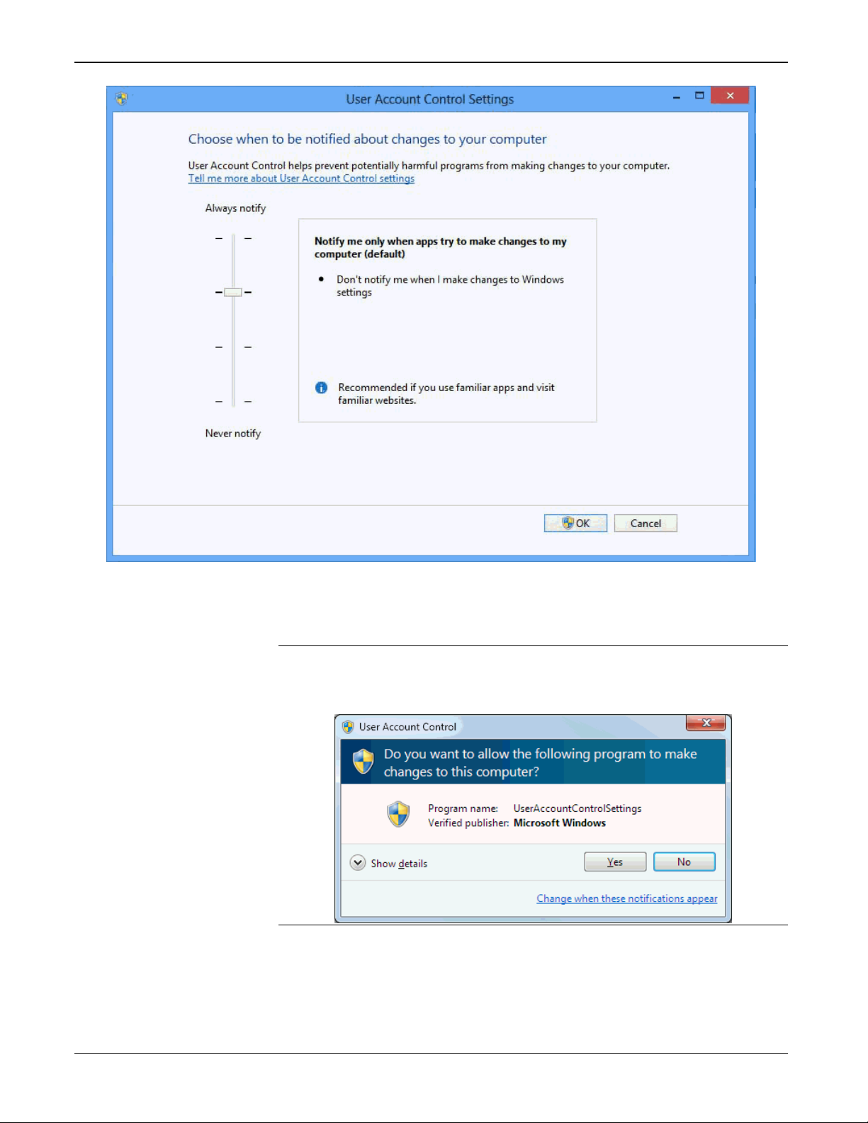
4. Move the User Account Control slider to Never Notify.
1-6 Introduction Revised August-2020

ROCLINK 800 Configuration Software User Manual (for FloBoss 107)
Figure 1-3. User Account Control Settings (Windows 10)
5. Click OK to save your changes and close the User Account Control
Settings window.
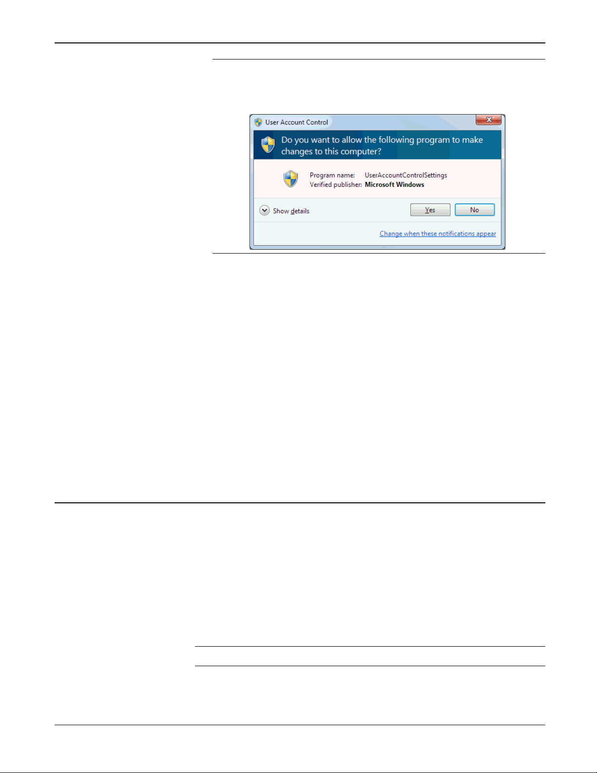
Note: You must have Administrator rights to make this change.
Click Yes (and enter Administrator password if necessary) if
Windows asks if you want to allow the changes.
6. Reboot the computer for your changes to take effect.
7. Start ROCLINK 800. Refer to Starting ROCLINK 800 Software
(located in this chapter).
Disabling User Account Control (Windows 8)
Note: User Account Control must remain disabled in order to run
ROCLINK 800.
1. To disable User Account Control:
2. Select Search and type UAC into the Search field.
Revised August-2020 Introduction 1-7

ROCLINK 800 Configuration Software User Manual (for FloBoss 107)
Figure 1-4. Search (Windows 8)
3. Select Settings and click Change User Account Control settings.
.
Figure 1-5. Setting – Results for “uac” (Windows 8)
4. Move the User Account Control slider to Never Notify.
1-8 Introduction Revised August-2020

ROCLINK 800 Configuration Software User Manual (for FloBoss 107)
Figure 1-6. User Account Control Settings (Windows 8)
5. Click the OK button to save your changes and close the User Account
Control Settings window.
Note: You must have Administrator rights to make this change. Click
Yes (and enter Administrator password if necessary) if Windows
asks if you want to allow the changes.
6. Reboot the computer for your changes to take effect.
7. Start ROCLINK 800. Refer to Starting ROCLINK 800 Software
(located in this chapter).
Revised August-2020 Introduction 1-9

ROCLINK 800 Configuration Software User Manual (for FloBoss 107)
Disabling User Account Control (Windows 7)
Note: User Account Control must remain disabled in order to run
ROCLINK 800.
To disable User Account Control:
1. Select Start and type MSCONFIG in the Search field.
2. Click the program file msconfig.exe. The System Configuration
screen displays.
Figure 1-7. System Configuration (Windows 7)
3. Click the Tools tab.
1-10 Introduction Revised August-2020

ROCLINK 800 Configuration Software User Manual (for FloBoss 107)
Figure 1-8. Change UAC Settings (Windows 7)
4. Select Change UAC Settings.
5. Click Launch. The User Account Control Settings window displays.
Figure 1-9. User Account Control Settings (Windows 7)
6. Move the User Account Control slider to Never Notify.
Revised August-2020 Introduction 1-11

ROCLINK 800 Configuration Software User Manual (for FloBoss 107)
7. Click OK to save your changes and close the User Account Control
Settings window.
Note: You must have Administrator rights to make this change. Click
Yes (and enter the Administrator password if necessary) if
Windows asks if you want to allow the changes.
.
8. Reboot the computer to apply the changes.
9. Start ROCLINK 800. Refer to Starting ROCLINK 800 Software
(located in this chapter).
Changing Region Settings (Windows 10)
To avoid potential error when opening configuration files, we recommend
that you change your PC’s location to United States.
To change your PC’s location:
1. Right-click the Start menu and select Search from the pop-up menu.
1-12 Introduction Revised August-2020

ROCLINK 800 Configuration Software User Manual (for FloBoss 107)
Figure 1-10. Pop-Up Menu (Windows 10)
Revised August-2020 Introduction 1-13

ROCLINK 800 Configuration Software User Manual (for FloBoss 107)
2. Type region into the search field.
Figure 1-11. Search (Windows 10)
3. Click Region in the results list.
4. Select the Location tab.
5. Change or verify that the current location is set to United States.
1-14 Introduction Revised August-2020

ROCLINK 800 Configuration Software User Manual (for FloBoss 107)
Figure 1-12. Home Location (Windows 10)
6. Click OK button to save changes and close the Region window.
Changing Region Settings (Windows 8)
To avoid potential error when opening configuration files, we recommend
that you change your PC’s location to United States.
To change your PC’s location:
1. Select Search and type region into search field.
Revised August-2020 Introduction 1-15

ROCLINK 800 Configuration Software User Manual (for FloBoss 107)
Figure 1-13. Search (Windows 8)
2. Select Settings and click Region in the results list.
Figure 1-14. Search Results (Windows 8)
3. Change or verify that the current location is set to United States.
1-16 Introduction Revised August-2020

ROCLINK 800 Configuration Software User Manual (for FloBoss 107)
Figure 1-15. Home Location (Windows 8)
7. Click the OK button to save changes and close the Region window.
Changing Region Settings (Windows 7)
To avoid potential error when opening configuration files, we recommend
that you change your PC’s location to United States.
To change your PC’s location:
1. Select Start > Control Panel. The Control Panel displays:
Revised August-2020 Introduction 1-17

ROCLINK 800 Configuration Software User Manual (for FloBoss 107)
Figure 1-16. Control Panel (Windows 7)
2. Select Clock, Language, and Region. The Clock, Language, and
Region screen displays:
Figure 1-17. Clock, Language, and Region (Windows 7)
3. Click Change location. The Region and Language screen
displays showing the Location tab.
1-18 Introduction Revised August-2020

ROCLINK 800 Configuration Software User Manual (for FloBoss 107)
Figure 1-18. Region and Language (Windows 7)
4. Change or verify that the current location is set to United States.
5. Click the OK button to save your changes.
Enabling User Account Control (Windows 10)
Note: User Account Control must remain disabled in order to run
ROCLINK800.
To enable User Account Control:
Revised August-2020 Introduction 1-19

ROCLINK 800 Configuration Software User Manual (for FloBoss 107)
1. Right-click the Start menu and select Search and from the pop-menu.
Figure 1-19. Pop-Up Menu (Windows 10)
2. Type UAC into the search field.
1-20 Introduction Revised August-2020

ROCLINK 800 Configuration Software User Manual (for FloBoss 107)
Figure 1-20. Search (Windows 10)
3. Click Change User Account Control settings in the results list.
4. Move the User Account Control slider to the default position.
Revised August-2020 Introduction 1-21

ROCLINK 800 Configuration Software User Manual (for FloBoss 107)
Figure 1-21. User Account Control Settings (Windows 10)
5. Click OK to save your changes and close the User Account Control
Settings window.
Note: You must have Administrator rights to make this change. Click
Yes (and enter Administrator password if necessary) if
Windows asks if you want to allow the changes.
6. Reboot the computer for your changes to take effect.
7. Start ROCLINK 800. Refer to Starting ROCLINK 800 Software
(located in this chapter).
Enabling User Account Control (Windows 8)
Note: User Account Control must remain disabled in order to run
ROCLINK800.
To disable User Account Control:
1. Select Search and type UAC into the search field.
1-22 Introduction Revised August-2020

ROCLINK 800 Configuration Software User Manual (for FloBoss 107)
Figure 1-22. Search (Windows 8)
1. Select Settings and click Change User Account Control settings.
Figure 1-23. Setting, Results for “uac” (Windows 8)
2. Move the User Account Control slider to the default position.
Revised August-2020 Introduction 1-23
ROCLINK 800 Configuration Software User Manual (for FloBoss 107)
Figure 1-24. User Account Control Settings (Windows 8)
3. Click OK button to save your changes and close the User Account
Control Settings window.
Note: You must have Administrator rights to make this change. Click
Yes (and enter the Administrator password if necessary) if
Windows asks if you want to allow the changes.
4. Reboot the computer for your changes to take effect.
5. Start ROCLINK 800. Refer to Starting ROCLINK 800 Software.
1-24 Introduction Revised August-2020

ROCLINK 800 Configuration Software User Manual (for FloBoss 107)
Enabling User Account Control (Windows 7)
Note: User Account Control must remain disabled in order to run
ROCLINK 800.
To enable User Account Control:
1. Select Start and type MSCONFIG in the Search field.
2. Click the program msconfig.exe. The System Configuration screen
displays:
Figure 1-25. System Configuration (Windows 7)
3. Click the Tools tabs.
Revised August-2020 Introduction 1-25

ROCLINK 800 Configuration Software User Manual (for FloBoss 107)
Figure 1-26. Change UAC Settings (Windows 7)
4. Select Change UAC Settings.
5. Click Launch. The User Account Control Settings screen displays.
Figure 1-27. User Account Control Settings (Windows 7)
6. Move the User Account Control slider to the default position.
7. Click OK to save your changes and close the User Account Control
Settings window.
1-26 Introduction Revised August-2020
ROCLINK 800 Configuration Software User Manual (for FloBoss 107)
Note: You must have Administrator rights to make this change. Click
Yes (and enter the Administrator password if necessary) if
Windows asks if you want to allow the changes.
.
8. Reboot the computer to apply your changes.
9. Start ROCLINK 800. Refer to Starting ROCLINK 800 Software
(located in this chapter).
1.4.2 Un-installing ROCLINK 800
To remove ROCLINK 800 from your PC:
1. Click the Windows Start button.
2. Select Settings > Control Panel.
3. Double-click the Add/Remove Programs icon.
4. Select ROCLINK 800.
5. Click Add/Remove.
6. Follow the displayed instructions.
1.5 Starting ROCLINK 800 Software
To use ROCLINK 800 to configure a hardware device, you must first
properly connect the device to power. Refer to the appropriate hardware
instruction manual. You must also connect the PC to the device’s Local
Operator Interface (LOI), serial, or modem port.
To run ROCLINK 800, perform one of the following steps:
Double-click the Desktop Shortcut.
Select Start > Programs > ROCLINK 800 > ROCLINK 800.
The software loads and initializes.
Note: You can only run one version of ROCLINK 800 at a time.
Revised August-2020 Introduction 1-27

ROCLINK 800 Configuration Software User Manual (for FloBoss 107)
1.5.1 Logging On
To log on to ROCLINK 800 software:
1. Connect the FB107 to the Local Operator Interface (LOI – Local
Port) and launch ROCLINK 800.
Figure 1-28. Logon
2. Type your assigned 3-character identifier in the User ID field and
press Enter or Tab.
Note: The User ID is case sensitive.
Typically, your initials are your user ID. If user IDs have not yet been
assigned, try using the default user ID of LOI. You assign user IDs by
using the ROC > Security features of ROCLINK 800.
3. Type your assigned 4-digit password and click OK. For added
security, the software displays an asterisk for each number that you
type. If passwords have not yet been assigned, use the default
password of 1000 (valid only with the default user ID of LOI).
ROCLINK 800 validates the user ID and password you enter against a
predefined list.
If the log on is not valid, a dialog box appears. Click OK and re-enter
the user ID and password. You can repeat the procedure as many
times as needed until you successfully enter a valid User ID and
password. If the log on is valid, ROCLINK 800 displays the Device
Directory screen (see Figure 2-1).
To exit the log on screen, click Cancel or press Esc. This closes
ROCLINK 800 and returns you to the point where you started ROCLINK
800.
1-28 Introduction Revised August-2020

ROCLINK 800 Configuration Software User Manual (for FloBoss 107)
Menu
Menu Options
File
New, Open, Download, Close, Save Configuratio n, Print
Configuration, Print, Print Setup, [List of recent files], Exit
Edit
Undo, Cut, Copy, Paste.
Note: This option is not available in the current release.
View
Directory, EFM Report, Cal i b ration Report, History,
Alarms, Events, Display, I/O Monitor, Toolbar
ROC
Direct Connect, Disconnect, Collect Data, Clock,
Security, Comm Ports, Memory, Information, Flags
Configure
I/O, Control, History Points, Opcode Table, MODBUS,
LCD User List, User Data
Meter
Setup, Calibration, Values, Plate Change
1.6 User Interface Basics
You interact with ROCLINK 800 using various displays on the computer
monitor, keyboard, and pointing device.
The major components of ROCLINK 800 user interface are:
Graphical Interface (Splash Screen)
Menu bar and menus.
Toolbar.
Function screens.
Dialog boxes.
Help system, including the Status bar and message boxes.
Device Directory or Configuration Tree menu.
ROCLINK 800 employs a dynamic graphical user interface (GUI) with a
standard Windows menu structure. After you log on to ROCLINK 800,
available functions display in a menu bar with drop-down menus. A
Status Line at the bottom left of the display contains pertinent
information about the highlighted item, such as a menu option or a
parameter.
Buttons display dialog boxes for further configuration details or perform
a desired action, such as the Update button. To activate the button:
Click the button with a left click of the mouse.
When a button is active, press Enter or a function key.
Dialog boxes are areas that “pop up” inside the current screen allowing
you to make further selections or enter values. Dialog boxes can also
provide messages or more detailed information.
The menu structure lists choices from which you can select the desired
function. Once you select a function, the screen or dialog box for that
function displays. This screen or dialog box provides the requested
information and lets you enter the applicable configuration data.
Table 1-1. Menu Listing for ROCLINK 800
Revised August-2020 Introduction 1-29

ROCLINK 800 Configuration Software User Manual (for FloBoss 107)
Menu
Menu Options
Utilities
Update Firmware, License Key Administrator, Convert
Editor, Read File From Device, Communications Monitor
Tools
Options
Window
Cascade, Tile, Device Directory, [List of open windows]
Help
Help Topics, About ROCLINK 800
EFM File, User Program Administrator, ROCLINK 800
Security, AI Calibration Values, MVS Calibration Values,
FST Editor, Custom Display Editor, Custom EFM Report
1.6.1 The FloBoss 107 Dynamic Interface
You can navigate the FB107 options either by using the ROCLINK menu
structure or by clicking on the FB107 graphical dynamic interfac e and
selecting a tab or button. The dynamic interface display shows the current
settings of the point including alarms and integrity.
The system displays a white line around objects that are links when you
hover your cursor over them. A link descriptor displays indicating what
the link is for. The system displays a yellow line around currently
selected components. The configuration for the selected hardware
displays at the bottom of the screen.
Note: For more information on using the dynamic interface, refer to
SupportNet course RAS-0044 FB107 Dynamic Interface.
1-30 Introduction Revised August-2020

ROCLINK 800 Configuration Software User Manual (for FloBoss 107)
Figure 1-29. FloBoss 107 Dynamic Interface
Figure 1-30. Integrity Alarm
Revised August-2020 Introduction 1-31

ROCLINK 800 Configuration Software User Manual (for FloBoss 107)
Alarms
The FB107 supports two kinds of alarms: integrity (which indicate
Integrity
Integrity notifications indicate hardware problems related to the CPU
Alarm
Alarm notifications indicate problems related to field or other user-
hardware problems) and alarms (which indicate software or field
device problems).
Alarm notifications display on both the graphical representation of the
FB107 and on the tabbed screen below the graphical FB107. ROCLINK
800 color-codes the notifications to help you quickly identify and resolve
the alarms. Integrity notifications display as an I in a red box and alarm
notifications display as an A in a yellow box (see Figure ). Moving the
mouse over these alarm icons displays a definition. ROCLINK 800 also
displays definitions in the Integrity field.
module, I/O modules (Auxiliary 6-Point IO), the CPU module’s
optional I/O assembly (On-Board 6-Point IO), MVS modules,
communication modules, and smart application modules.
Other integrity notifications can include:
Red “I” – Integrity. The point is out of the user-defined or default range.
For example, when an AI is open, the actual AD count is 0 but the default
range is 643 to 3220 or loss of communications occurred.
Communication Failure: The FB107 sets a diagnostic error
indicating Communication Failure if the Actual Module field is
empty and the Installed Module field displays a value or if
communications is lost between the FloBoss and the module. Refer to
Actual versus Installed Module (located in this chapter).
Module Mismatch: Displays if you install a different module type
than the one currently displayed in the Installed Module field, which
draws from information residing in the CPU configuration.
Out of Range: Indicates that the point is not within the user-defined
configured parameters.
Integrity Failure: Displays when the FB107 cannot read or
communicate with the associated hardware. The hardware reports a
malfunction.
defined values.
The FB107 dynamic interface displays an A in a yellow box to indicate
an alarm condition (see Figure ). The alarm condition indicates the type
of point and location associated with the installed hardware point.
ROCLINK 800 displays alarms when you enable the
Yellow “A” – Alarm. The point is in alarm condition. The Active
Alarms fields indicate any alarms that are active for this point. When
Alarming is set to Enabled, the active alarms appear. If Alarming is
set to Enabled, an alarm is generated when Scanning is Disabled.
Even if Alarming is Disabled, the Integrity Failure (hardware
malfunction) alarm indicator can still appear.
1-32 Introduction Revised August-2020

ROCLINK 800 Configuration Software User Manual (for FloBoss 107)
1.6.2 Actual versus Installed Module
As a diagnostic tool, the General tab in the window underneath the FB107
dynamic interface includes two fields, Installed Module and Actual
Module. The Actual Module field indicates what module is physically
installed in the backplane. The system updates this field whenever you
restart the FB107. The Installed Module field indicates the module
identified in the configuration file currently residing in firmware.
If the contents of the Actual Module and Installed Module fields are not
identical, the system displays integrity alarms. You then correct the
integrity errors. The FloBoss 107 remembers the “Installed Module” type
until you “Uninstall” it.
The FB107 uses a plug and play system to install newly inserted modules
to the backplane. For example, in a new FB107 with no installed
modules, the Actual Module field displays “Empty” for all slots. The
Installed Module field also displays “Empty” for all slots.
When you insert an I/O module in slot 2 and power up the FB107, the
FB107 displays Aux IO in the Actual Module field. The FB107 also
displays Aux IO in the Installed Module field (since there was not a
module previously installed in slot 2) and creates the I/O points
associated with the I/O module.
If you remove the I/O module from slot 2 and power up the FB107, the
Actual Module field now displays Empty, but the Installed Module field
still displays Aux IO. The FB107 “remembers” what was previously
installed. Additionally, the FB107 sets an integrity error (specifically,
“Communication Failure”) on slot 2 because the slot is now physically
empty and the Installed Module field indicates Aux IO. You can still
define and manage the I/O points associated with the Installed Module
(Aux I/O), but because of the unresolved integrity error any I/O points are
marked in point fail.
A Module Mismatch error occurs if you install a different type of
module than currently displays in the Installed Module field.
To completely remove a module from the FB107 click Uninstall. This
resets the value in the Installed Module field to Empty and deletes any
I/O points associated with the previously installed module.
Note: The FB107 completely re-scans for actual and installed modules if
you select ROC > Flags, click Flash Memory Clear on the Flags
screen, and click Cold Start & Clear All.
Revised August-2020 Introduction 1-33

ROCLINK 800 Configuration Software User Manual (for FloBoss 107)
window.
Apply
1.6.3 Standard Buttons
Several buttons appear on most ROCLINK 800 screens.
Button Description
Minimizes and hides windows.
Maximizes the size of the windows to fit in the screen area.
Restores window to original size.
Closes a window.
Expands options listed in the Device Directory or
Configuration Tree Menu.
Hides options listed in the Device Directory of
Configuration Tree Menu.
Prints the active display.
1.6.4 Toolbar Buttons
The following buttons appear in the ROCLINK 800 toolbar. ROCLINK
800 grays out a button if it is not applicable to the current screen.
Button Description
Updates contents of the active window from the devi ce.
Applies changes on the active window to the device and
closes the active window. A Confirm Sav e di al og box
displays if there are unsaved changes.
Cancels without saving changes and close the active
Applies changes on the active window to the device.
Clicking
Starts automatic device polling.
Stops automatic device polling.
Creates a new configuration file. You specify available
configuration parameters using menu selections. Configure the
file as if you were connected to the device. Functions requiring a
live connection are unavailable in this mode.
Opens an existing configuration file. You create configuration
files using the New Device or Save Configuration functions.
does not close the active window.
Saves the current configuration of the connected device to a
disk file.
1-34 Introduction Revised August-2020

ROCLINK 800 Configuration Software User Manual (for FloBoss 107)
Note
Button Description
Deletes currently selected text and place it in the Clipboard.
Note: Currently not available.
Copies currently selected text and places it in the Clipboard.
Note: Currently not available.
Pastes text currently in the Clipboard at the cursor’s current
location.
: Currently not available.
Prints the configuration file.
Note: Currently not available.
Connects to a device locally using the (LOI) Local Operator
Interface port.
Disconnects from a device.
Displays the first of two .DSP files loaded on the de vice.
Note: Not available on the FB107.
Displays the second of two .DSP files loaded on the device.
Note: Not available on the FB107.
Displays the Analog Input (AI) screen.
Displays the Discrete Input (DI) screen.
Displays the Pulse Input (PI) screen.
Displays the Analog Output (AO) screen.
Displays the Discrete Output (DO) screen.
Displays the Comm Port screen.
Displays the Flags screen.
Displays the Clock screen.
Displays the Meter Setup screen.
Displays the Plate Change screen.
Displays the PID Loop screen.
Revised August-2020 Introduction 1-35
ROCLINK 800 Configuration Software User Manual (for FloBoss 107)
Option
Description
Modules
I/O
Information
Meter
History
Button Description
Opens the Function Sequence Table (FST) Editor.
Displays an About ROCLINK 800 screen providing program
information, version, creation date, and copyri ght for ROCLINK
800.
Launches the ROCLINK 800 on-line help system.
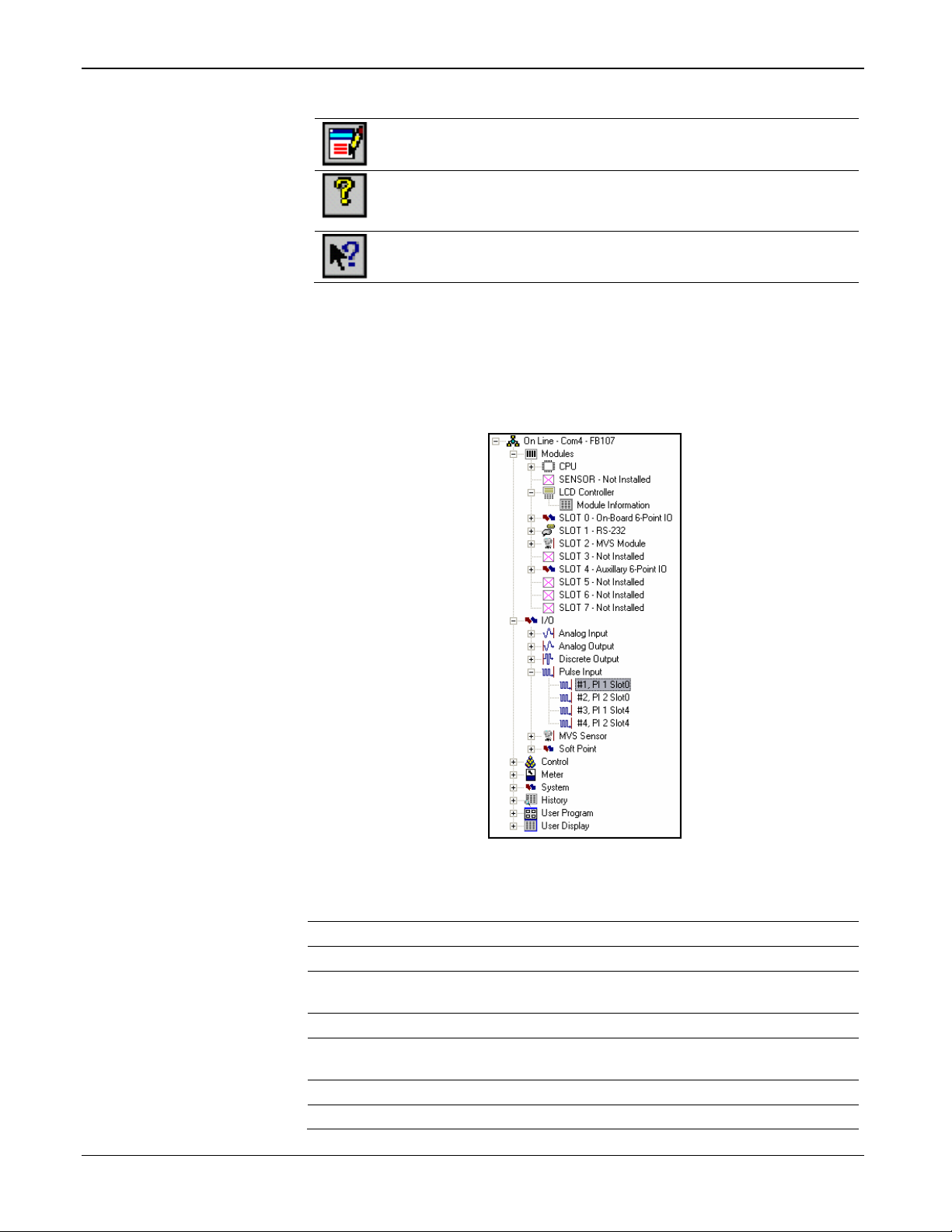
1.6.5 Configuration Tree Menu
When you open a configuration file or go on-line with an FB107, the
Configuration Tree appears on the left-hand side of the screen. The tree
hierarchically displays the parts of a configuration (such as I/O, Meter
Runs, and History) that you can change.
1-36 Introduction Revised August-2020
Figure 1-31. Configuration Tree
Lists all installed modules.
Lists all available inputs and outputs by type.
Control Displays the FST and PID options enabled on the ROC >
screen.
Lists all available meters.
System Displays ROC > Information system folders, Comm Port,
Device Flags, and the Opcode Table.
Displays all available History Points.
User Programs Displays all installed user programs.

ROCLINK 800 Configuration Software User Manual (for FloBoss 107)
User Display Accesses custom displays stored in the FB107. The
From the Configuration Tree, you may change the configuration or
monitor current operations. Once you are in the Configuration Tree menu,
you can use the + and – symbols to display or hide various options.
Double-click the desired function in the Configuration Tree to display the
associated screen. Double-clicking an icon is the same as selecting the
menu bar or Toolbar button option.
If this is the first time that you have connected to the FloBoss, refer to
Section 6.4, Setting the Clock (located in Chapter 6).
1.6.6 Keystrokes
If you are using the keyboard, you may use the Alt key plus one or more
letters to access menus. Windows underlines the appropriate letter in the
menus. For example, to access the Open File dialog box, press Alt + F
and press O. You may also use the Left Arrow (←) and Right Arrow (→)
keys to highlight a menu bar item (the help Status Line at the bottom of
the screen provides a description of the menu) and press the letter.
FB107 can store a maximum of 40 displays (including
both custom user displays and user program displays).
With a menu displayed, you can highlight the desired item by using the
Down Arrow (↓) and Up Arrow (↑) keys or the mouse. Once you have
highlighted an item, press Enter to activate the function.
To leave a menu or submenu, press Esc. You can then select another
menu. You can also access another menu using ← and →.
The text scrolling keys are Page Up and Page Down.
To use the keyboard in configuration screens and dialog boxes, press Tab
to move in a predetermined sequence from one parameter field or button
to the next. The selected field or button becomes highlighted. Fields
unavailable for changes are automatically skipped.
When you Tab to the last field or button in the screen or dialog box,
pressing Tab again jumps back to the first field or button. To go back to a
previous field or button, press Shift + Tab.
In an option field, the currently selected option is highlighted. To select
one of the other options, use ↓ or ↑ to highlight the desired option and
then press Enter.
In a field that requires a text or numerical entry, type in the required
characters or numbers from the keyboard. Use Backspace or Delete to
erase unwanted characters. Use ← and → to move the cursor one
character at a time and Home and End to place the cursor at the
beginning and end of the field, respectively.
Other keys or key combinations include:
F1 – Launches ROCLINK 800 on-line help.
Revised August-2020 Introduction 1-37

ROCLINK 800 Configuration Software User Manual (for FloBoss 107)
Option
Description
Search
Back
Print
Esc – Cancels the current activity, closes the screen, and returns you
to the last-used place in the menu structure, screen, or other place
from which the dialog box originated. If a menu is active, Esc closes
the last-opened menu, taking you up one level in the menu structure.
If the menu bar is active, Esc de-selects all menu options. Press Alt or
click with the mouse to reactivate the menu bar.
Ctrl + N – Creates a new configuration file.
Ctrl + O – Opens a configuration file.
Ctrl + S – Saves the current configuration file.
1.6.7 Help System
The Help menu provides detailed on-screen information about getting
started with ROCLINK 800 and performing keyboard operations, a list of
the Help topics, and the ROCLINK 800 version.
To display context sensitive help on a menu item, a parameter, or a
button, press F1 while the item, parameter, or button is highlighted. A
help window appears on the screen.
To view detailed help, select Help > Help Topics from the menu bar.
Contents Presents a list of Help Topics that display based on task-
Index Locates specific Help Topics. The Index lists each f i el d by the
See Also Displays topics related to the currently selected topic.
<< / >> Navigates forward (>>) or backwards (<<) through the help
1.6.8 Basic Navigation
When you start ROCLINK 800, the Device Directory displays. After you
connect to an FB107, the Configuration Tree displays (see Figure ).
oriented situations. Each screen, tab, and field has a help
topic associated with it. For example: the Modbus Scale
Values tab is located under Modbus > Modbus
Configuration > Scale Values tab.
tab or screen in which the field appears.
Activates a search function on a specific word.
Returns to the last topic that you viewed.
Sends the currently displayed topic to the PC’s default printer.
system on a per topic basis. The Browse Sequence follows
the order of the topics as displayed in the Contents tab.
1-38 Introduction Revised August-2020
Use the + and – symbols to display or hide various options. Double-click
a point to display the associated parameter configuration screen. You can
also use the menu options and buttons to display the associated parameter
configuration screen.
ROCLINK 800 Configuration Software User Manual (for FloBoss 107)
The Status Line at the bottom of the Device Directory and Configuration
Tree provides critical information. The left side displays brief information
about the device being connected. The right side displays the device
status (on-line or off-line) and system time.
TLP Selections
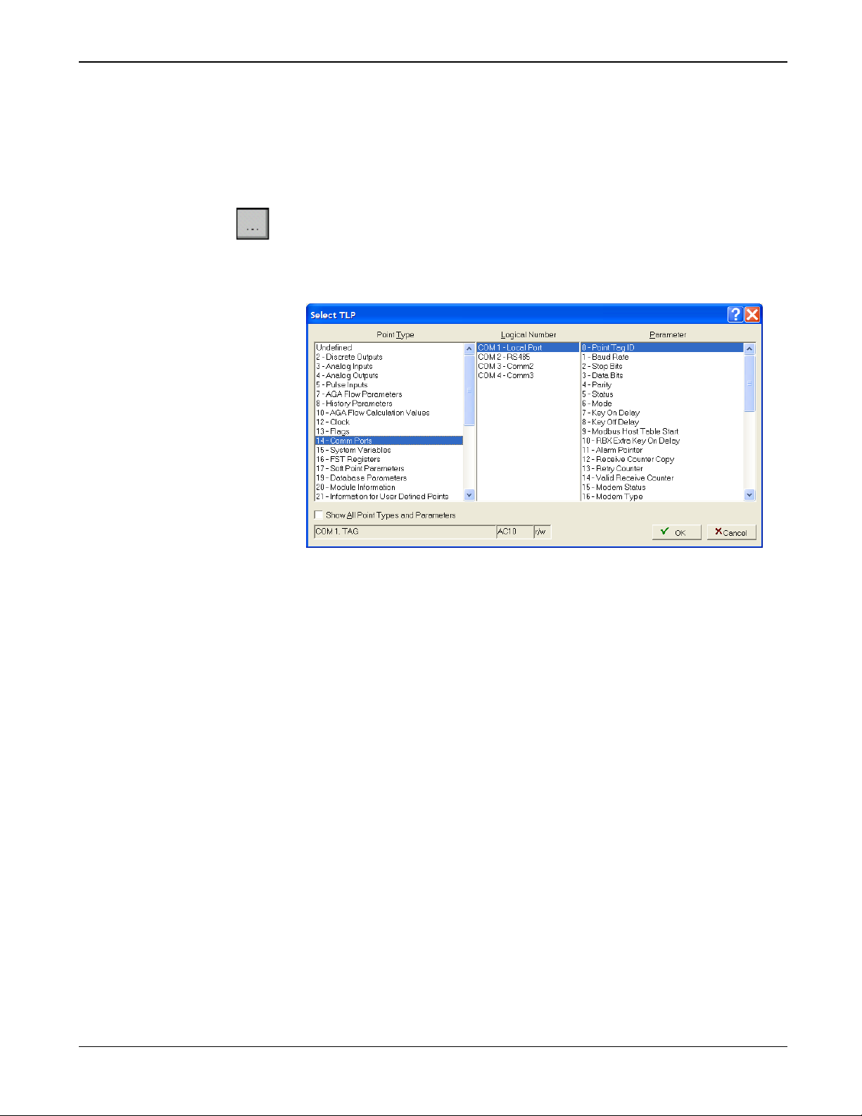
In many locations in ROCLINK 800, you can click Browse (a button
with three dots) to view the Select TLP dialog. The Select TLP dialog
allows you to assign specific inputs and outputs to parameters.
ROCLINK 800 uses Point Type (T), Logical Number (L), and
Parameter (P) to define point locations.
Figure 1-32. Select TLP
AutoScan Update
Interval Option
To use the Select TLP dialog box:
1. Select the Point Type from the list. This opens a list of logical
numbers and parameters that belong to that Point Type.
2. Select the Logical Number. In the configuration screens, the Logical
Number is generally referred to as Point Number or Number.
3. Select the specific Parameter. These are usually called by the same
term as the Tag on the configuration screen. Click OK.
The field at the bottom of the Select TLP dialog displays the numeric
point location of the TLP point or a text abbreviation, depending on
the setting in the Tools > Options window.
Select Tools > Options to set the time interval, in seconds, at which the
AutoScan feature on various screens in ROCLINK 800 polls the FB107.
Clicking AutoScan causes ROCLINK 800 to poll the device
automatically, until you click StopScan.
Revised August-2020 Introduction 1-39

ROCLINK 800 Configuration Software User Manual (for FloBoss 107)
1.6.9 Text Boxes
Text boxes appear in various places throughout ROCLINK 800. You can
enter alphanumeric character (A through Z and 0-9) into text boxes. For
example, you can enter name (tag) for a device or a short description for
an I/O point.
1-40 Introduction Revised August-2020

ROCLINK 800 Configuration Software User Manual (for FloBoss 107)
Chapter 2 – Device Directory and Device Root
In This Chapter
2.1 Device Directory ...................................................................................... 2-1
2.1.1 Communication Parameter Setup Screen .................................. 2-2
2.2 Device Root ............................................................................................. 2-4
2.2.1 Backing Up Configurations ......................................................... 2-4
2.2.2 Adding a Group .......................................................................... 2-5
2.2.3 Deleting a Group ........................................................................ 2-5
2.2.4 Deleting a Device ....................................................................... 2-5
2.2.5 Adding a Device ......................................................................... 2-6
2.2.6 Deleting All Devices ................................................................... 2-6
2.2.7 Renaming a Group or Device ..................................................... 2-7
This chapter describes the Device Directory screen and the Device Root,
the graphical representation of all devices, which appears on that screen.
2.1 Device Directory
The Device Directory is the first screen that displays after you
successfully log onto ROCLINK 800 but before you connect to a device.
Figure 2-1. Device Directory and Device Root
Note: Once you connect to a device, ROCLINK 800 replaces the Device
Directory screen with a device-specific configuration tree screen
(see Figure 2-2).
Revised August-2020 Device Directory and Device Root 2-1
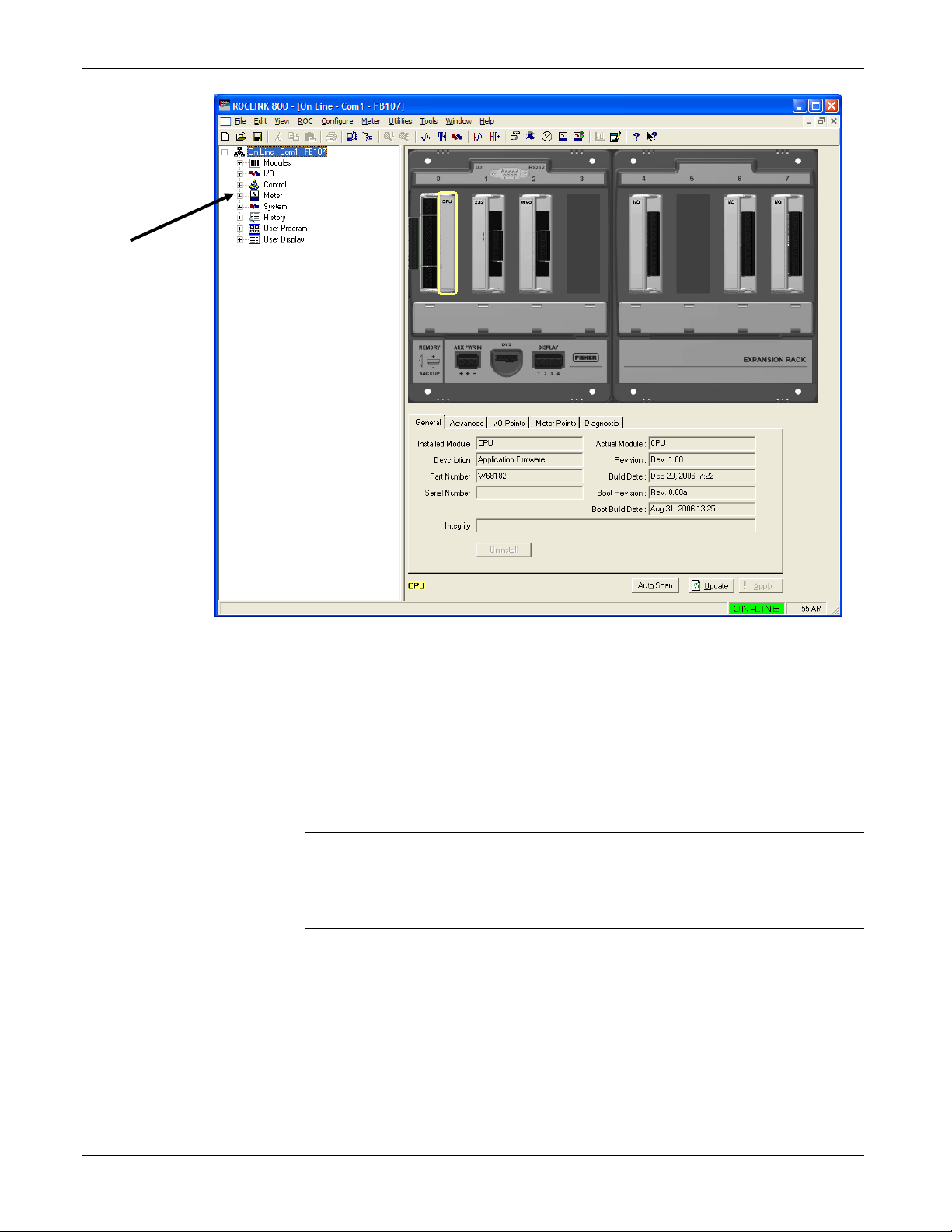
ROCLINK 800 Configuration Software User Manual (for FloBoss 107)
Figure 2-2. Configuration Tree
You use the Device Directory screen (Figure 2-1) to create and maintain
communications setup configurations for a PC running ROCLINK 800.
You can uniquely configure the communication ports on the PC to send
data to a specified FB107. You may add, delete, or modify these
communications setups and establish a tree of groups and devices.
Use the + and – symbols to display or hide various options.
Note: You can only configure a PC’s communications ports from the
Device Directory screen. To redisplay the Device Directory screen
at any time, select Window > Device Directory or View >
Directory.
2.1.1 Communication Parameter Setup Screen
The ROCLINK 800 Communication Parameter Setup screen allows you
to change your PC communications port, time-out settings, and other
variables ROCLINK 800 uses when establishing a connection to a device.
In order for ROCLINK 800 to communicate with a device, ROCLINK
800 must know to which device it is communicating. Each device within
a group is given a unique device address.
2-2 Device Directory and Device Root Revised August-2020

ROCLINK 800 Configuration Software User Manual (for FloBoss 107)
To set the PC communication parameters:
1. Right-click the label in the Device Directory that corresponds to the
PC port you want to use.
Figure 2-3. Device Pop-up Menu
2. Select Properties. The ROCLINK 800 Communication Parameters
screen displays.
Figure 2-4. Communication Parameters
Revised August-2020 Device Directory and Device Root 2-3

ROCLINK 800 Configuration Software User Manual (for FloBoss 107)
Device Root
3. Configure the ROCLINK 800 communications parameters (refer to
Chapter 3, Communications and Security for a complete discussion of
this screen).
4. Click Apply. You are ready to connect to the FB107.
2.2 Device Root
The device root graphically represents the devices and their
organizational structure on the Device Directory screen. When you open
ROCLINK 800, the device root displays the default device labels. Using
the Communication Parameters screen, you can modify the
communications setup configurations for these devices or add new
devices with new configurations. Each icon on the device root represents
a different type of communications connection.
Figure 2-5. Device Root
The default device labels, which correspond to available communication
ports, include:
COM1 Device.
COM2 Device.
Modem Device.
Ethernet Device.
New Group1.
You may add, delete, or modify the communication configurations for
each of these devices. You can also define device groups.
2.2.1 Backing Up Configurations
After you configure your device settings, we strongly recommend that
you create a back-up file of those settings. ROCLINK 800 stores these
values in the file ROC_USER.mdb. Use Windows Explorer to find the
ROC_USER.mdb file, then copy the file and store it in a safe place. This
2-4 Device Directory and Device Root Revised August-2020
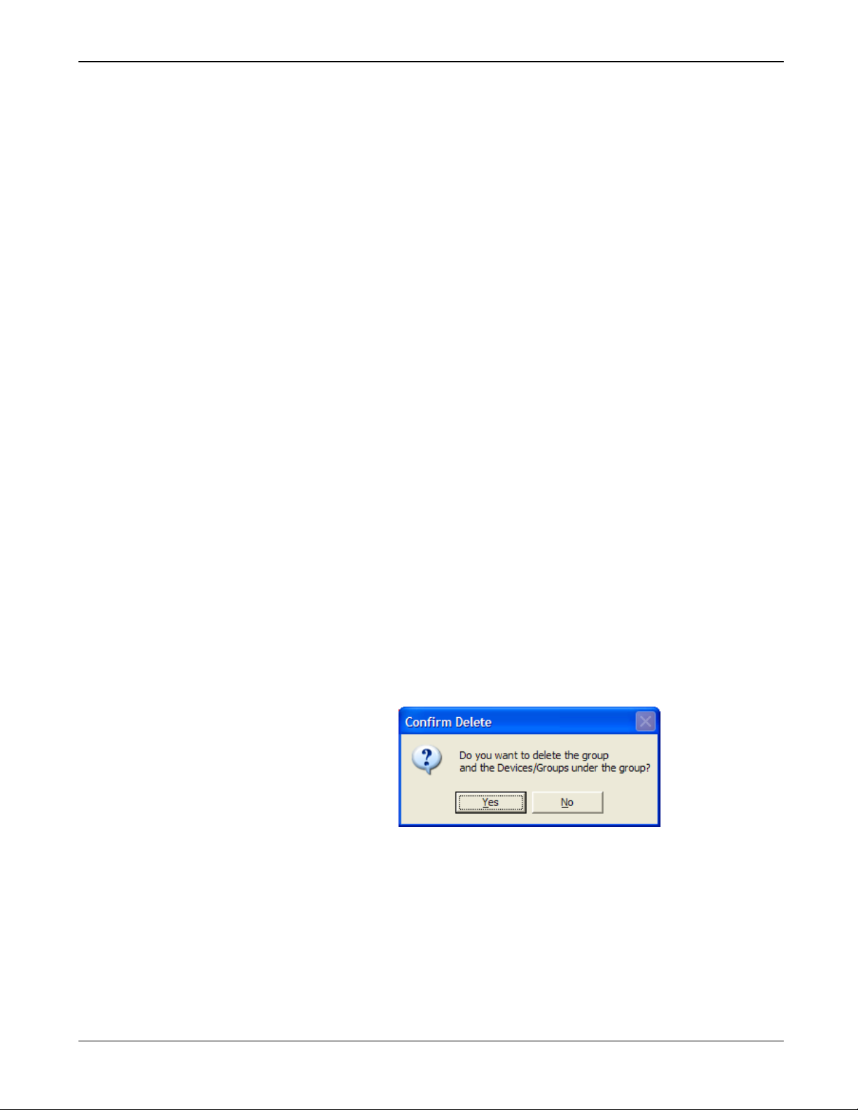
ROCLINK 800 Configuration Software User Manual (for FloBoss 107)
backup file enables you to restore your settings in case they ever become
corrupted.
You can configure devices on-line communications using the Local
Operator Interface (LOI) Port (also known as the “local port”) or a
communication port, such as a modem.
For differentiation, each FB107 has a tag and a unique device address
which you define on the ROCLINK 800 Communications Parameters
screen (see Figure 2-4). The Device Address must be different from any
other host system that may access the network.
2.2.2 Adding a Group
You can organize devices into groups. Typically, groups contain devices
in the same geographical area or with another common feature. When you
double-click a group icon, ROCLINK 800 displays all devices or
subgroups associated with that group.
To add a new group to the device root directory:
1. Right-click the Device Root icon. A pop-up menu displays.
2. Select Add a Group. ROCLINK 800 adds the new group icon to the
device root graphic.
To add a subgroup to an existing group:
1. Right-click the group icon. A pop-up menu displays.
2. Select Add a Group. ROCLINK 800 adds the new group icon to the
selected group.
2.2.3 Deleting a Group
To delete a group:
1. Right-click a group icon. A pop-up menu displays.
2. Select Delete Group. A Confirm Delete dialog box displays.
3. Click Yes to delete the group and all subordinate groups and devices
in that group.
Figure 2-6. Delete Group
2.2.4 Deleting a Device
To delete a device:
1. Right-click a device icon. A pop-up menu displays.
Revised August-2020 Device Directory and Device Root 2-5

ROCLINK 800 Configuration Software User Manual (for FloBoss 107)
2. Select Delete Device. A Confirm Delete dialog box displays.
Figure 2-7. Delete Device
3. Click Yes to delete the device.
2.2.5 Adding a Device
To add a new device to the device root:
1. Right-click the device root icon. A pop-up menu displays.
2. Select Add a Device. ROCLINK 800 adds a device icon to the device
root.
3. Configure the new device’s communication parameters (see Chapter
3, Communications and Security).
To add a device to an existing group:
1. Right-click the group icon. A pop-up menu displays.
2. Select Add a Device. ROCLINK 800 adds a device icon in the
selected group.
3. Configure the new device’s communication parameters (see Chapter
3, Communications and Security).
2.2.6 Deleting All Devices
To delete all device communication parameter configurations in the
device root directory:
Note: This deletes all devices you currently have configured.
1. Right-click the device root icon. A pop-up menu displays.
2. Select Delete All Devices. A Confirm Delete dialog box displays.
Figure 2-8. Delete All Devices
2-6 Device Directory and Device Root Revised August-2020

ROCLINK 800 Configuration Software User Manual (for FloBoss 107)
3. Click Yes. ROCLINK 800 deletes all devices in the device root.
2.2.7 Renaming a Group or Device
You can easily replace the ROCLINK 800-provided default group or
device names with names you choose. To rename a group or device in the
Device directory:
1. Right-click the device or group icon. A pop-up menu displays.
2. Select Rename. Enter a name.
Note: Although your label can be up to 72 characters in length, keep
the label short for easy recognition.
3. Press Enter when finished. ROCLINK 800 adds the new label to the
device or group.
Revised August-2020 Device Directory and Device Root 2-7

ROCLINK 800 Configuration Software User Manual (for FloBoss 107)
[This page is intentionally left blank.]
2-8 Device Directory and Device Root Revised August-2020

ROCLINK 800 Configuration Software User Manual (for FloBoss 107)
Chapter 3 – Communications and Security
In This Chapter
3.1 Communications .............................................................................. 3-1
3.2 ROCLINK 800 Communications ...................................................... 3-2
3.2.1 ROCLINK 800 Communications Parameters
General Tab........................................................................ 3-2
3.2.2 ROCLINK 800 Communications Parameters
Advanced Tab .................................................................... 3-4
3.3 Communication Ports on the FB107 ............................................... 3-6
3.4 Communication Modules ................................................................. 3-7
3.4.1 Dial-up Modem Module ...................................................... 3-7
3.4.2 Enhanced Communication Module .................................... 3-9
3.4.3 Network Radio Module ..................................................... 3-10
3.5 Configuring FB107 Communications Ports ................................... 3-13
3.5.1 Comm Ports – General Tab ............................................. 3-13
3.5.2 Comm Ports – Modem Tab .............................................. 3-15
3.5.3 Comm Ports – RBX Tab ................................................... 3-16
3.5.4 Comm Ports – ECM General ............................................ 3-18
3.5.5 Comm Ports – ECM Advanced ........................................ 3-20
3.5.6 Network Radio Module – Network Tab ............................ 3-22
3.5.7 Network Radio Module – Advanced Tab .......................... 3-22
3.6 Connecting to an FB107 ................................................................ 3-23
3.6.1 Direct Connect .................................................................. 3-24
3.6.2 Local Port (LOI) ................................................................ 3-24
3.6.3 Connect to a FloBoss ....................................................... 3-25
3.6.4 Successful Logon ............................................................. 3-25
3.6.5 Disconnecting from a FloBoss .......................................... 3-26
3.7 Troubleshooting Connection Errors .............................................. 3-26
3.7.1 Troubleshooting ROCLINK 800 Communications............ 3-26
3.8 Security .......................................................................................... 3-27
3.8.1 ROCLINK 800 Security .................................................... 3-27
3.8.2 Device Security ................................................................ 3-31
This chapter describes how to configure the communication ports on a PC
and on an FB107. It also describes how to use the Connect and Direct
Connect features in ROCLINK 800 and how to define security to control
access to the FB107 and ROCLINK 800.
3.1 Communications
Before you attempt to connect to an FB107, you must configure
communication parameters in two places:
ROCLINK 800 Communications
Configure device communications on the Device Directory screen
(see Chapter 2, Device Directory and Device Root). This sets the
PC’s comm ports to communication with a specific device.
Communication Ports on the FB107
Select ROC > Comm Ports to access the Comm Port screen and
Revised August-2020 Communications and Security 3-1

ROCLINK 800 Configuration Software User Manual (for FloBoss 107)
configure the FB107’s communication ports for incoming or outgoing
communications. Refer to Section 3.3, Communication Ports on the
FB107.
3.2 ROCLINK 800 Communications
The Device Directory communication configurations allow ROCLINK
800 to communicate to an individual FB107.
3.2.1 ROCLINK 800 Communications Parameters General Tab
The Device Directory screen is the first screen that displays after you
successfully log onto ROCLINK 800 but before you connect to a device.
To display the ROCLINK 800 Communication Parameters screen, rightclick on a device icon in the device root and select Properties. The
ROCLINK 800 Communication Parameters screen displays, showing the
General tab.
Use the General tab to configure basic communications for the PC
running ROCLINK 800.
Figure 3-1. ROCLINK 800 Communications, General tab
Field Description
Tag Sets a unique name for the FB107. Enter up to 50
alphanumeric characters to identify the FB107.
3-2 Communications and Security Revised August-2020

ROCLINK 800 Configuration Software User Manual (for FloBoss 107)
port.
Device Address
Note
240
Field Description
Connect
Device Group Associates the FB107 with a specific group. The
Host Address Identifies the PC’s host address, which by default is
Host Group Identifies the PC’s host group, which by default is 1.
Use Sets t he type of connection. Valid values are Comm
PC Comm Port Sets the comm port on the PC ROCLINK 800 uses
Click to communicate with the PC using the
parameters configured for this PC’s communications
Sets the address of the specific FB107 with which
you desire to communicate. If you are connected to a
multi-drop series of devices, enter the device
address and device group of a specific device.
: The default device address is
default device group is 240.
Note: If you connect a PC running ROCLINK 800
directly to the device’s LOI (Local Port),
ROCLINK 800 makes a request to Device
Group of 240 and Device Address of 240. The
Local Port of a device always responds to a
request for Address 240 and Group 240, no
matter what Device Address and Device
Group is configured in the device if the LOI
Security is valid.
Address 3. If more than one computer running
ROCLINK 800 communicates with a group of
devices (either by radio or by other multi-drop
communications), you must define unique host
address for each device to avoid multiple responses.
The host address must also be different from any
other host system that may access the
communications link.
Use the following host group and host address
conventions: 0 and 240 are reserved.
When using ROC Protocol, the group address must
match the address defined at the destination device
in order for communications to properly transmit.
Use the following host group and host address
convention: 0 and 240 are reserved.
Port, Modem, or TCP/IP.
Note: If you select TCP/IP, ROCLINK 800 applies
only the Time Out parameter you define on
the Advanced tab. No other parameters
defined on that tab apply.
for this setup. The FB107 can communicate t hrough
any of the PC’s configured comm ports. The default
comm port is 1.
Note: This field is available only if you select the
Comm Port option. Before you select this
parameter, check to see which
communications ports are assigned in the PC.
.
Revised August-2020 Communications and Security 3-3

ROCLINK 800 Configuration Software User Manual (for FloBoss 107)
Modem
Modem
TCP/IP
Field Description
PC Baud Rate Sets the baud rate ROCLINK 800 uses to
communicate with the device through a serial port
(COM port). For successful communications, the
baud rate you set here must match the baud rate on
the PC. The default value is 19200.
Note: This field is available only if you select the
Comm Port option.
Modem Indicates the modem ROCLINK 800 uses. Click to
list all available modems. Only the modems defined
in the Windows’ Control Panel display here. Ensure
that the modem you select is properly set up.
Note: This field is available only if you selected the
option.
Phone Number Sets the telephone number for the modem ROCLINK
800 uses. If you select Modem in the Use field, enter
the phone number of the device ROCLINK 800 dials.
Note: This field is available only if you selected the
Modem option.
Override Default
TAPI Init String
IP Address Indicates the IP address for the TCP/IP conne ct ion.
Port Number Indicates the port for the TCP/IP connection.
Indicates that ROCLINK 800 should use an over ride
initialization string configuration. When y ou select
this optoin, you must provide an override initialization
string.
Note: This field is available only if you selected the
option.
Note: This field is available only if you selected the
TCP/IP option.
Note: This field is available only if you selected the
option.
3.2.2 ROCLINK 800 Communications Parameters Advanced Tab
Use the Advanced tab on the ROCLINK 800 Communication Parameters
screen to configure advanced communications features.
3-4 Communications and Security Revised August-2020
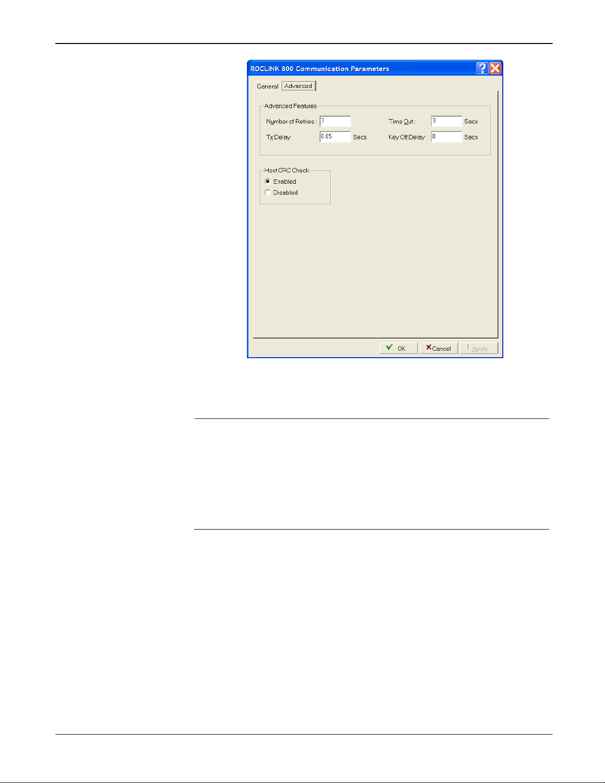
ROCLINK 800 Configuration Software User Manual (for FloBoss 107)
Field
Description
Figure 3-2. ROCLINK 800 Communications, Advanced tab
Number of Retries Sets the number of times (after the initial attempt)
ROCLINK 800 tries to request data from the
specified device before reporting a timeout error.
Valid values are between 0 and 25. The default is 3.
Use the Time Out parameter to adjust the amount of
time between retries.
Note: This parameter does not apply to the dial-up
modem, which only tries to establish a
connection once.
Revised August-2020 Communications and Security 3-5

ROCLINK 800 Configuration Software User Manual (for FloBoss 107)
radios, a value of 0.01 may be appropriate.
Host CRC Check
Field Description
Tx Delay Sets, in seconds, the amount of time ROCLINK 800
waits before transmitting data. This delay enables the
request-to-send (RTS) line for the amount of delay
specified before transmitting data. The default is
0.05.
Typically, this value allows a radio to fully stabil ize
before the system applies data for transmission.
For EIA-232 (RS-232) and dial-up modem
communications, set this value (and the value i n
the Key Off Delay field) to 0 (zero) or the default
of 0.05 seconds.
For EIA-485 (RS-485) and radio communications,
set this value to 0.1.
Note: These variables may change, based on your
situation. These are general values which you
need to assess for each circumstance.
Time Out Sets, in seconds, the actual amount of time that
ROCLINK 800 waits to receive a valid message after
it sends a request to a device. The default is 3.
Modem users typically accept the default value.
Do not set this field to 0 (zero). This prevents
ROCLINK 800 from timing out, and quickly exhausts
the Retries.
Note: If you select TCP/IP as the communications
method on the General tab, ROCLINK 800
applies only the Time Out parameter. No
other parameters defined on that tab apply.
Key Off Delay Sets, in seconds, the amount of time ROCLINK 800
waits after transmitting a message before turning off
the ready to send (RTS) signal. The default is 0. You
can change this value to optimize communications.
The default value should be sufficient for dial-up
modems and EIA-232 (RS-232) connections. For
3.3 Communication Ports on the FB107
3-6 Communications and Security Revised August-2020
Indicates whether ROCLINK 800 uses cyclical
redundancy checking. The default value is Enabled.
In addition to configuring the communications ports on the PC, you also
configure the device-specific communication parameters.
While in a configuration and on-line with an FB107, select ROC >
Comm Ports to display the Comm Port screen. Each communications
port has a unique set of parameters on the screen.
Use the Comm Ports screen to set up the communications ports that are
available for incoming and outgoing communications with the FloBoss.
Note: Use the Device Directory to define PC communication ports.

ROCLINK 800 Configuration Software User Manual (for FloBoss 107)
Comm Port
Port Location
Type
Protocols
LOI
CPU
Local Port / RS-232C
ROC or Modbus slave
COM1
CPU
EIA-485 (RS-485)
ROC or Modbus host/slave
COM2
CPU
EIA-232 (RS-232) − Default
ROC or Modbus host/slave
COM3
Module Slot 1
EIA-232 (RS-232) or EIA-485 (RS-485)
ROC or Modbus host/slave
COM2
Module Slot 2
EIA-232 (RS-232) or EIA-485 (RS-485)
replaces COM2 on the CPU.
ROC or Modbus host/slave
DISPLAY
DISPLAY
EIA-232 (RS-232) [Limited Function]
ROC or Modbus slave
The communication ports located on the FB107 provide a data link to
ROCLINK 800, other devices, and host systems. The type of module
enables the following communications:
EIA-232 (RS-232) serial communications.
EIA-485 (RS-485) multi-point serial communications.
Table 3-1. Communication Ports for the FloBoss 107
Note: When installed in Slot 2, the module
3.4 Communication Modules
You can navigate FB107 options using the ROCLINK menu structure or
by clicking on components of the FB107 graphic (such as modules, tabs,
or buttons). The graphical interface display shows the current settings of
the point including alarms and integrity.
You can install a communication module in slot 1 or 2 on the main
FB107. When a communication module is installed in slot 2, the
communication port (COM2) on the CPU is redirected to the type of
module installed in slot 2.
To display the communication port for the FB107, click the
communications module on the graphical interface.
3.4.1 Dial-up Modem Module
The Dial-up Modem Module provides communication over a Public
Switched Telephone Network (PSTN) at up to 2400 bits per second (bps).
The module plugs into the main board of the FB107, which provides
power and control signals to activate COM2 or COM3. Refer to
FloBoss™ 107 Flow Manager Instruction Manual (part D301232X012)
for more details.
Revised August-2020 Communications and Security 3-7
Each communication module uses a separate channel from the other
modules and has a common ground (single-ended). The field interface
protects the electronics in the module. Each module reduces the effect of
noise on communication errors through filtering.

ROCLINK 800 Configuration Software User Manual (for FloBoss 107)
The FB107 supports communication protocols, including ROC protocol
and Modbus protocol. An FB107 can act as a Modbus slave device
(ASCII or RTU) on COM2 or COM3.
To access the Dial-up Modem:
1. Select Directory Tree > Modules > SLOT X - Dial-up Modem
(where X is the slot number where the module is installed).
2. Double-click Dial-up Modem.
3. The Module Information displays at the bottom of the user interface.
Figure 3-3. Modem Module
Note: The description for each field is located in Section 3.4.3 –
Network Radio Module.
3-8 Communications and Security Revised August-2020

ROCLINK 800 Configuration Software User Manual (for FloBoss 107)
3.4.2 Enhanced Communication Module
The Enhanced Communication Module (ECM) provides communications
over a four session Ethernet port and a Universal Serial Bus (USB) 2.0
port. Refer to FloBoss™ 107 Flow Manager Instruction Manual (part
D301232X012) for more details.
You can install up to two ECMs in the same FB107, using slots 1 and/or
2. The module plugs into the main board of the FB107, which provides
power and control signals to activate COM2 or COM3. When a
communication module is installed in slot 2, the communication port
(COM2) on the CPU is redirected to the type of module installed in slot 2.
Each communication module uses a separate channel from the other
modules and has a common ground (single-ended). The field interface
protects the electronics in the module. Each module reduces the effect of
noise on communication errors through filtering.
The FB107 supports communication ROC Plus protocols, Modbus
master/slave (ASCII or RTU), and Modbus TCP.
Note: If you configure the FB107 to poll devices using the
communication ports on the ECM, be aware that downloading
large files using the communications ports on the ECM may
prevent the FB107 from performing the configured polls during
the file download period. Polling continues as expected after the
file is downloaded and no data loss occurs. To avoid this issue, do
not download user programs or display files using the
communications ports on the ECM while performing mission
critical functions.
To access the Enhanced Communication Module:
1. Select Directory Tree > Modules > SLOT X - Enhanced Comm
Module (where X is the slot number where the module is installed).
2. Double-click Enhanced Comm Module.
3. The Module Information displays at the bottom of the user interface.
Revised August-2020 Communications and Security 3-9
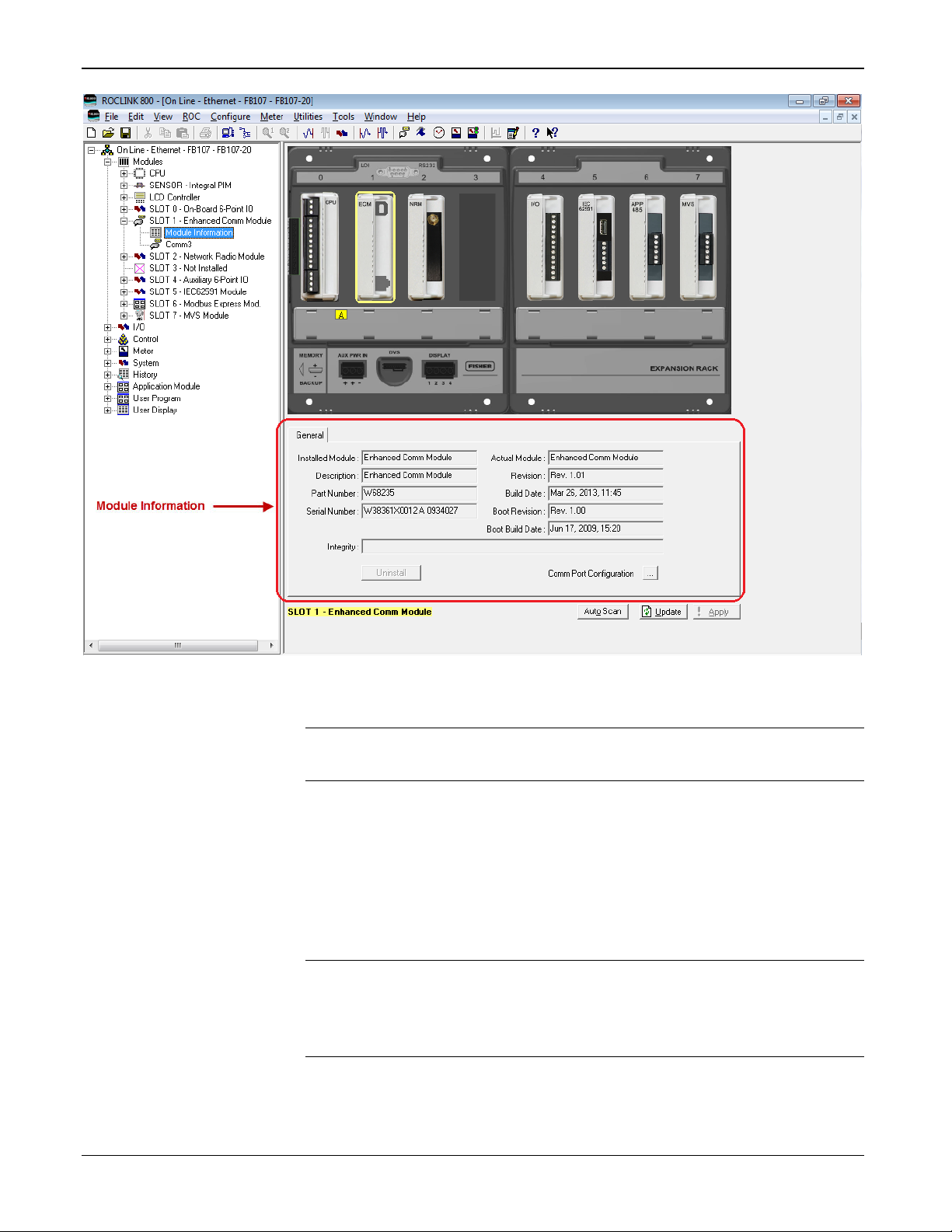
ROCLINK 800 Configuration Software User Manual (for FloBoss 107)
Figure 3-4. Enhanced Communication Module (ECM)
Note: The description for each field is located in Section 3.4.3 –
Network Radio Module.
3.4.3 Network Radio Module
The NRM provides a wireless solution of transferring data from one RTU
to another RTU within the Distributed RTU Network (DRN). The data
can be any type of information that the RTU has in its database, such as
I/O, soft points, or other information. Refer to Distributed RTU™
Network Instruction Manual (part D301727X012) for more details
Note: In an FB107, you can install the NRM in either slot 1 or 2 (the
slots immediately to the right of the CPU) of the base unit. You
cannot install the NRM in any slot on an FB107 expansion unit.
The FB107 supports only one NRM.
To access the Network Radio Module, click on the NRM module on the
graphic image of the FB107 (see Figure 3-5) or:
3-10 Communications and Security Revised August-2020

ROCLINK 800 Configuration Software User Manual (for FloBoss 107)
Field
Description
hardware currently installed in the FB107.
1. Select Directory Tree > Modules > SLOT X - Network Radio
Module (where X is the slot number where the module is installed).
2. Double-click Module Information. The NRM module information
displays at the bottom of the user interface.
Revised August-2020 Communications and Security 3-11
Figure 3-5. Network Radio Module (NRM)
Installed Module This read-only field shows the module currently
defined in the active FB107 configuration. ROCLINK
800 does not require that a module be physically
installed to display. Refer to Section 1.6.2, Actual
versus Installed Module.
Description This read-only field shows a description of the

Integrity
read-only
ROCLINK 800 Configuration Software User Manual (for FloBoss 107)
Field Description
Part Number For ECM and NRM:
This read-only field shows the part number of the
firmware currently installed in the FB107.
For Modem:
This read-only field shows the part number of the
hardware currently installed in the FB107.
Serial Number For ECM and NRM:
This read-only field shows the serial number of the
hardware currently installed in the FB107.
For Modem:
This field is blank.
Actual Module This read-only field shows the module physically
installed in the backplane. ROCLINK 800 updates
this field whenever you restart the FB107. Refer to
Section 1.6.2, Actual versus Installed Module.
Revision For ECM and NRM :
This read-only field shows the firmware revision for
the hardware currently installed in the FB107.
For Modem:
This field is blank.
Build Date For ECM and NRM:
This read-only field shows the date the firmware was
built for the hardware currently installed in the
FloBoss 107.
For Modem:
This field is blank.
Boot Revision For ECM and NRM:
This read-only field shows the version for the main
startup (“boot”) firmware currently installed i n the
module.
For Modem:
This field is blank.
Boot Build Date For ECM and NRM:
This read-only field shows the build date for the
main startup (“boot”) firmware currently installed in
the module.
For Modem:
This field is blank.
This
status of the hardware currently installed in the
FB107.
The user interface displays alarms that indicate t he
state of the hardware (CPU, I/O modules, CPU I/O
assembly, MVS modules, and communication
modules). Mousing over an alarm displays a short
explanation of the alarm. Refer to Section 1.6.1,
FloBoss 107 User Interface.
field shows a message regarding the
3-12 Communications and Security Revised August-2020

ROCLINK 800 Configuration Software User Manual (for FloBoss 107)
Installed Module.
Comm Port
For Modem:
Field Description
Uninstall
Click to remove the hardware definition current ly
installed in the active FB107 configuration. The
Installed Module field displays the type of module the
FB107 is using for point configuration. It does not
require that the module is physically installed in the
FB107 to display. The FloBoss 107 “remembers” the
type of installed module until you use this button to
uninstall it. Refer to Section 1.6.2, Actual versus
Configuration
Configure For NRM:
Click to display the Comm Port screen. Refer to
Section 3.5.1, Comm Ports – General Tab.
For ECM:
Click
Section 3.5.4, Comm Ports – ECM General and
Section 3.5.5, Comm Ports – ECM Advanced
Click to access the RTU screen. Refer to
to display the Comm Port screen. Refer to
Distributed RTU™ Network Instruction Manual
(part D301727X012), Section 3.2 -
Commissioning for details.
3.5 Configuring FB107 Communications Ports
The FB107 communication (“comm”) ports link the device to computers,
such as the one running ROCLINK 800 or a host computer.
You use the Comm Port screen to configure comm ports. After you select
a communications module on the FB107 graphic, click … in the lower
right portion of the screen. ROCLINK 800 displays the Comm Port
screen for that module or comm port.
Revised August-2020 Communications and Security 3-13
Note: You also access the Comm Port screen by selecting ROC >
Comm Ports from the ROCLINK 800 menu bar and then
selecting the appropriate comm port from the drop-down menu or
by selecting the (Comm) icon from the configuration tree.
After you completely configure all comm ports, save that configuration to
Flash memoryusing the Save Configuration button on the Flags screen
(ROC > Flags)
3.5.1 Comm Ports – General Tab
Select a comm module from the FB107 graphic, and then click … in the
lower right corner of the screen. ROCLINK 800 displays the Comm Port
screen for the selected module, which shows the General tab.
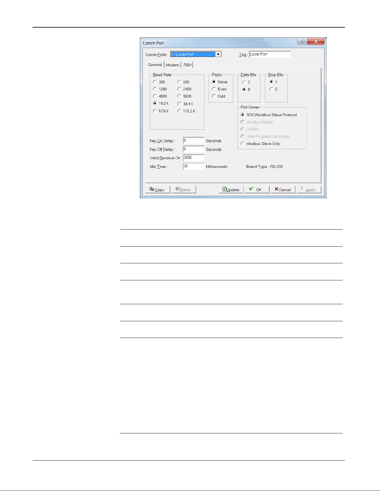
ROCLINK 800 Configuration Software User Manual (for FloBoss 107)
Parity
8
Stop Bits
Figure 3-6. Comm Port, General tab
Field Description
Comm Ports Indicates the specific comm port to be configured.
Click to display all valid selections.
Tag Sets a 10-character name (“tag”) to help identify the
comm port.
Baud Rate Sets, in bits per second, the transmit and receive
data baud rate for the comm port.
Indicates whether the communications controller
performs parity checks and, if selected, the parit y
value (odd or even).
Data Bits Sets the number of data bits contained in an
asynchronous byte, or character. The default is
Sets the number of stop bits contained in an
asynchronous byte, or character. The default i s 1.
Port Owner Sets the communications protocol this port uses.
Valid values are ROC/Modbus Slave Protocol
(which configures the port to automatically switch
between Modbus and ROC Protocol messages),
Modbus Master (which configures the port to allow
the FB107 to poll Modbus devices), DS800 (which
configures the port to download and debug
Development Suite 800 projects only), User
Program Controlled (which configures the Port to
use the communications protocol residing in the
loaded user program), Modbus Slave Only (which
configures the port to allow the FB107 to act only as
a Modbus slave device).
.
3-14 Communications and Security Revised August-2020
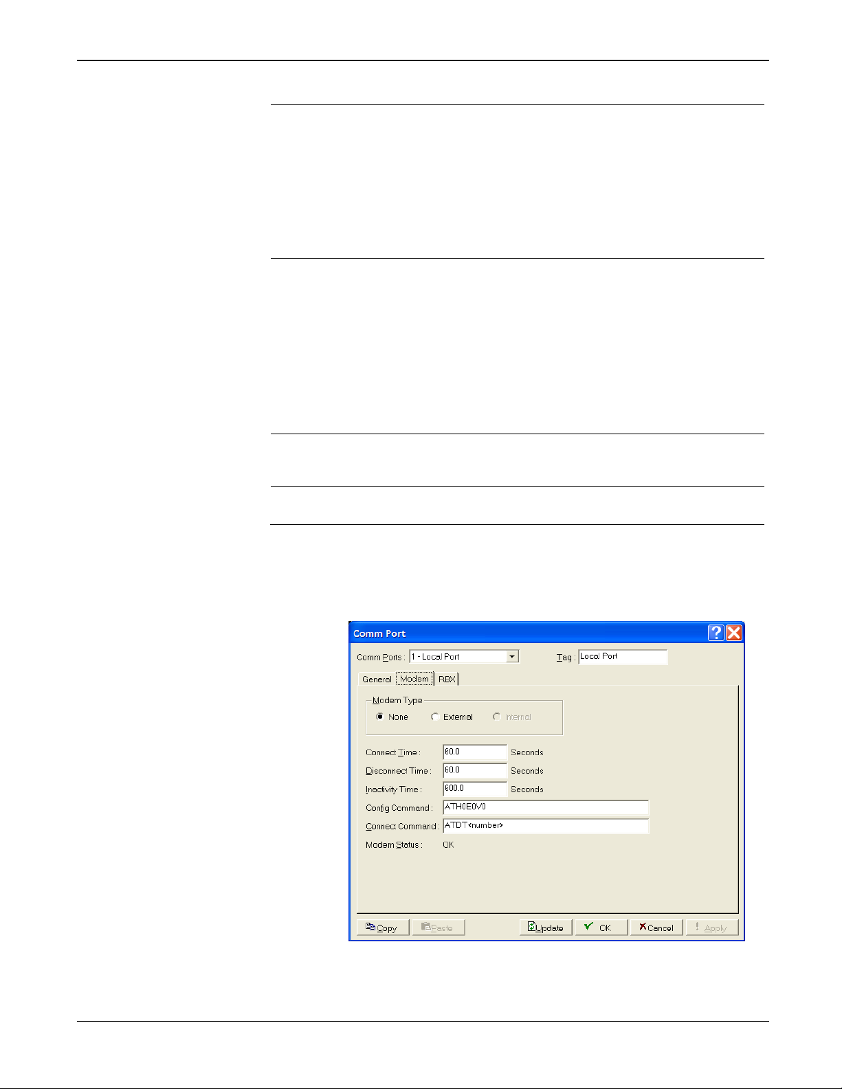
ROCLINK 800 Configuration Software User Manual (for FloBoss 107)
Field Description
Key On Delay
Key Off Delay Sets, in seconds, the amount of time ROCLINK 800
Valid Receive Ctr Sets the number of valid messages received by the
Idle Time Sets, in milliseconds, the amount of time the FloB oss
Sets, in seconds, the amount of time ROCLINK 800
waits after turning on the ready to send (RTS) signal
before beginning transmission. The default is 0. Y ou
can change this value to optimize communications.
The default value should be sufficient for dial-up
modems and EIA-232 (RS-232) connections. For
older radios, you may need to set this value to 0.2
seconds. For newer radios, 0.02 seconds should be
sufficient.
waits after transmitting a message before turning off
the ready to send (RTS) signal. The default is 0. You
can change this value to optimize communications.
The default value should be sufficient for dial-up
modems and EIA-232 (RS-232) connections. For
radios, a value of 0.01 may be appropriate.
Note: These variables may change, based on your
situation. These are general values which you
need to assess for each circumstance.
FloBoss on this communication port. This counter
can be preset to a value or cleared.
waits between communication events.
3.5.2 Comm Ports – Modem Tab
Use the Modem tab on the Comm Ports screen to configure the device’s
modem communication ports.
Figure 3-7. Comm Ports, Modem tab
Revised August-2020 Communications and Security 3-15

ROCLINK 800 Configuration Software User Manual (for FloBoss 107)
None
Connect Time
default Config Command characters.
Connect Command
OK
CONNECT
RING
NO DIAL TONE
BUSY
Field Description
Modem Type
Disconnect Time Sets, in seconds, the amount of time that ROCLINK
Inactivity Time Sets, in seconds, how long ROCLINK 800 waits
Config Command Sets the string of characters required to initialize the
Sets the modem type. Valid values are None (using
a serial link to the host), External (using an external
modem), and Internal (available on comm ports 2
and 3 when Modem module is installed). The default
is
Sets, in seconds, the amount of time that ROCLINK
800 waits after initiating a call to receive a connect
message from a device (typically the modem) before
it terminates the call. The default is 60 seconds.
The Connect Time varies from system to system
and can take up to 60 seconds to make and
complete a dial up connection. If a successful
connection is made, the Disconnect Time begins.
800 waits for further activity on the line before it
hangs up. ROCLINK 800 resets this timer after eac h
valid receive signal.
without receiving a signal before resetting the
modem. The inactivity timer looks at the valid receiv e
counter to determine if the signal has been recei ved.
modem. For external modems, refer to the
manufacturer’s literature. For an internal m odem , use
the default value or the modem card may not operate
correctly. Refer to your modem’s documentation f or
.
3.5.3 Comm Ports – RBX Tab
Sets the Hayes-style Connect Command required to
contact the host. Typically, this is the command
ATDT followed by the telephone number (for
example, ATDT5155551212). This parameter is
required only for dial-out operations, such as for
SRBX Alarming.
Modem Status This read-only field shows the modem’s current
status result code. Valid values are:
Successfully executed
command line
Connection established
Ring signal detected
NO CARRIER Carrier not detected/lost
ERROR Error in command line
No dial tone detected
Busy signal detected
NO ANSWER Line not picked up on the
called end
Use the RBX tab to configure the Spontaneous-Report-by-Exception
alarming features.
3-16 Communications and Security Revised August-2020
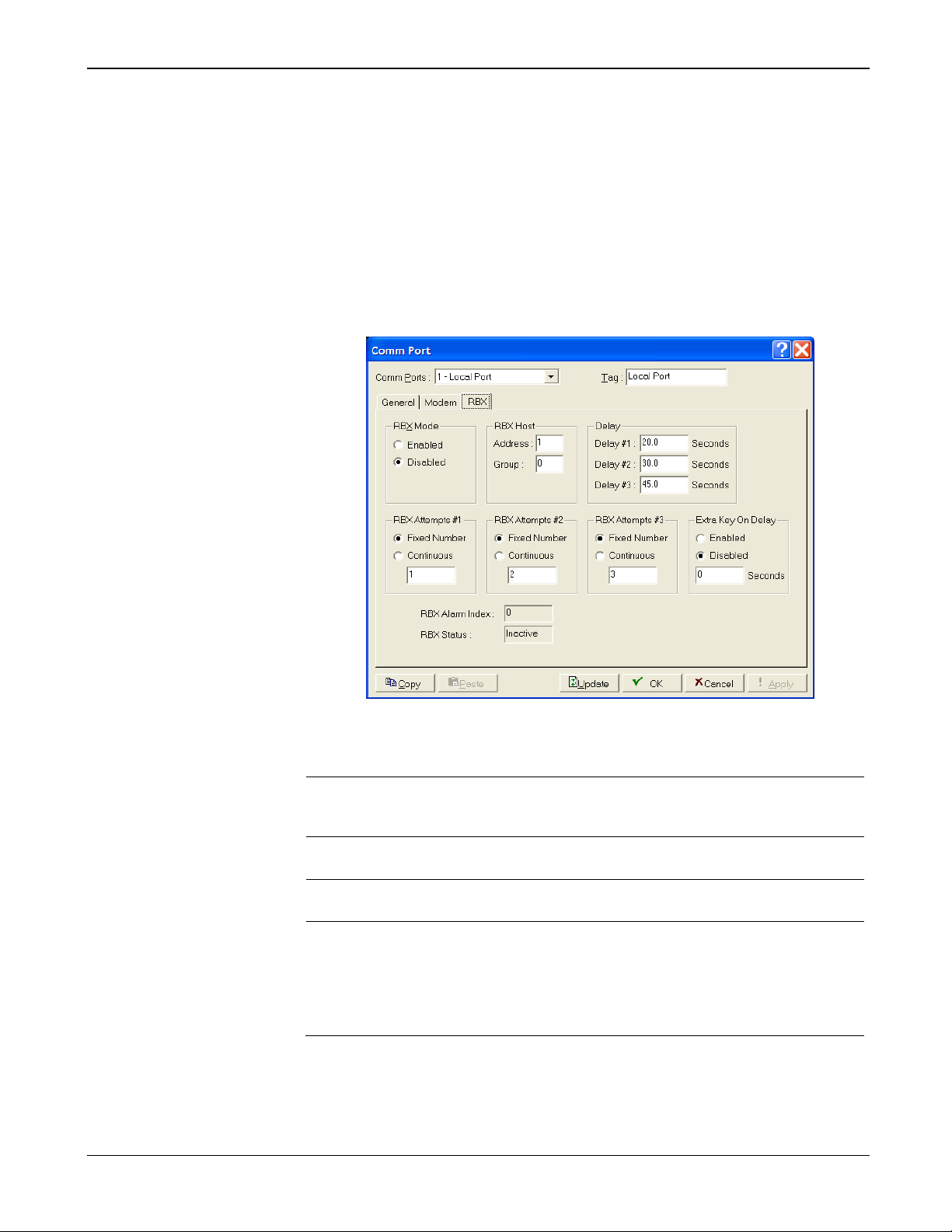
ROCLINK 800 Configuration Software User Manual (for FloBoss 107)
Field
Description
default for Delay #3 is 45 seconds.
The RBX or SRBX (Spontaneous Report-by-Exception) alarming feature
is available for serial communication ports. This feature allows the device
to call in to a host computer when a configured alarm occurs. If you wish
to configure dial-up RBX, then a modem must be present and
appropriately configured.
When you use RBX alarming, ensure that you enable and configure
alarms for each point you wish to monitor. Configure the alarm
parameters so that an alarm occurs only when desired. This prevents
“nuisance” alarms. You configure RBX alarm parameters on the Alarms
tab on the I/O, MVS, and Meter Setup configuration screens.
Figure 3-8. Comm Ports, RBX tab
RBX Mode Sets the RBX Mode for Spontaneous-Report-by-
Exception alarming on this comm port. The default is
Disabled.
Address Sets the address of the host to which the RBX
feature communicates.
Group Sets the group of the host to which the RBX feature
communicates.
Delay Sets, in seconds, the time the device waits between
attempts to transmit an RBX message. Each RBX
Attempts parameter has an associated delay
parameter. The default for Delay #1 is 20 seconds,
the default for Delay #2 is 30 seconds, and the
Revised August-2020 Communications and Security 3-17

ROCLINK 800 Configuration Software User Manual (for FloBoss 107)
Field Description
RBX Attempts Sets the number of times the device attempts to
resend a message if it does not obtain a valid
response on the first try. “Attempt” refers to t he i nitial
message plus any retries.
ROCLINK 800 provides three parameters. T he
default for all parameters is Fixed Number. The
default value for RBX Attempt #1 is 1, for RBX
Attempt #2 is 2, and for RBX Attempt #3 is 3.
Select Fixed Number to set how many times
ROCLINK 800 retries sending a message after the
first unsuccessful attempt. If you enter 0, no retries
occur. Select Continuous (255) to start continuous
retries that stop only when the host acknowledges
the SRBX alarm.
Extra Key On Delay Indicates whether ROCLINK 800 adds additional
delay time to the amount of time it waits after turning
on the ready to send (RTS) signal before sending an
RBX message.
Valid values are Disabled (the default) or Enabled.
If you select Enabled, you must also indicate the
number of seconds for the extra delay.
Note: This parameter may be required for radio
communications.
RBX Alarm Index This read-only field shows the alarm currently being
reported through RBX.
RBX Status This read-only field shows the status of RBX
messaging. Valid values are Active (an RBX alarm
is being processed) or Inactive.
3.5.4 Comm Ports – ECM General
Use this screen to setup communications parameters for the Enhanced
Communication Module.
To access this screen:
1. Click located beside Comm Port Configuration. The screen below
displays:
3-18 Communications and Security Revised August-2020

ROCLINK 800 Configuration Software User Manual (for FloBoss 107)
Field
Description
address is 10.0.0.2.
Subnet Mask
lead to communication disruptions.
Figure 3-9. Comm Ports, ECM General
MAC Address This read-only field shows the MAC Address for the
FloBoss 107. The Media Access Control Address
(MAC) Address is also referred to as t he Ethernet
address and is set at the factory
IP Address Sets the desired IP Address for the FB107. The
Internet Protocol (IP) Address will identify t he device
on a TCP/IP network. The factory-set default
Sets a value for the subnet mask portion of the IP
address. The subnet mask indicates the subnet to
which an IP address belongs. The factory-set default
is 255.255.255.0.
Gateway Address Sets the gateway address for the FB107. This value
identifies the network node that serves as an
entrance to the network on which the device resides.
The factory-set default is 10.0.0.1.
Caution: Do not leave the Gateway Addre ss field
blank. A blank Gateway Address field can
Revised August-2020 Communications and Security 3-19

ROCLINK 800 Configuration Software User Manual (for FloBoss 107)
This read-only field shows the total number of active
plus one Modbus Master connection.
0.
Reset All
Field Description
IP Port Number Sets the IP Port Number for the Modbus or ROC
Plus Protocol communications. The IP Port Number
determines which port that the ROC monitors for
Modbus or ROC Plus Protocol connections when
communicating over a TCP/IP connection. The ROC
Plus Protocol default is 4000. The Modbus default is
502. Port Numbers 1113 and 1131 are reserved.
If you change the Port Number, the change takes
effect immediately. If the default value of this
parameter is changed, then all Modbus or ROC Plus
Protocol over TCP/IP connections will be closed, and
you will have to re-establish a connection.
Inactivity Time Sets the time, in second s, ROCLINK 800 waits for a
valid Modbus or ROC Plus protocol message befor e
closing the connection. The default value is 3600.
This timer is in addition to the security timeout. Set
this field to zero (0) to disable the timer.
Active Connections
TCP/IP connections. The Ethernet port supports up
to four ROC protocol or Modbus Slave connections,
Address to Use Indicate s the protocol ad dress to use. Valid values
are Device Address, Slave Address, or Either
Device or Slave Address (default).
Slave Address Indicates, a specific address if you have chosen
Slave Address in the Address to Use frame. The
default is
Click to close all active Modbus or ROC Plus
Connections
Valid Receive Ctr Sets the number of valid messages received by the
Protocol over TCP/IP connections. This button
returns to an un-pressed state when connections are
successfully closed.
device on this communication port. You can preset or
clear this counter.
3.5.5 Comm Ports – ECM Advanced
Use this screen to configure the Gratuitous ARP functionality and to
configure automatic module re-initialization for the Enhanced
Communication Module.
When enabled, a Gratuitous ARP is broadcast on the network and enables
each device to pre-update its device listings. This feature allows a device
to join the network, and you can configure the rate at which the FB107
transmits a Gratuitous ARP.
Use the ECM Module Re-Initialization feature to re-establish
communications with the ECM. You can configure this feature to
automatically re-initialize the ECM module after a set amount of time
without activity on the selected protocols, or manually by clicking the
3-20 Communications and Security Revised August-2020

ROCLINK 800 Configuration Software User Manual (for FloBoss 107)
Field
Description
Reset ECM Module button, or by having SCADA write to the Reset ECM
Module parameter.
To access this screen:
1. Select the Comm Port Configuration button ( ). The Comm Port
screen displays showing the ECM General tab.
2. Select the ECM Advanced tab.
Figure 3-10. Comm Ports, ECM Advanced
Enable/Disable Select to enable or disable the Gratuitous ARP
functionality of the Enhanced Communication
module.
GARP Init Timer Sets, in minutes, the amount of time the FB107 waits
after you enable the Gratuitous ARP setting before
GARPing at the user-configured frequency. V al id
values are 5 – 50400.
Reset Click to reset the GARP Init Timer to the configured
value. No GARPing occurs if you click this button (or
SCADA writes to this parameter as a part of its
normal polling sequence) before the GARP Init Ti m er
expires.
Revised August-2020 Communications and Security 3-21

ROCLINK 800 Configuration Software User Manual (for FloBoss 107)
Init Timer field is reset. Valid values 5 – 86400.
Reset ECM Module
Sets, in seconds, the amount of time the system
automatically re-initializing the ECM.
the ECM.
Inactivity Counters
read-only
Field Description
GARP Frequency
Automatic Reset on
Inactivity
Inactivity Period
Sets, in seconds, the GARP interval. The FB107
repeats at this interval (frequency) until it the GARP
Click to manually re-initialize the Enhanced
Communication Module.
Note: Use this feature in the event the ECM
becomes unresponsive.
Select ROC Protocol and/or Modbus (107 as
Slave) to force the ECM to automatically re-initialize
after a user-configured amount of time without
activity on the selected protocol.
waits for activity using the selected protocols before
Valid Receive
Counters
These read-only fields indicate the number of valid
ROC protocol or TCP Modbus messages received by
These
in seconds, since the last message was received by
the ECM using ROC protocol and TCP Modbus.
3.5.6 Network Radio Module – Network Tab
Use this tab to configure the device as a Network Access Point (NAP) or
a Node and to define operational parameters for your network.
To access this screen, click the Network tab.
fields indicate the amount of time,
Note: The description for each field description, refer to Distributed
3.5.7 Network Radio Module – Advanced Tab
Use this screen to view additional read-only information about the
network.
To access this screen, select the Advanced tab.
3-22 Communications and Security Revised August-2020
Figure 3-11. Network Radio Module, Network Tab
RTU™ Network Instruction Manual (part D301727X012), Section
3.1.1 – Module Information: FB107, Network Tab for details.

ROCLINK 800 Configuration Software User Manual (for FloBoss 107)
Note: The description for each field description, refer to Distributed
RTU™ Network Instruction Manual (part D301727X012), Section
3.1.1 – Module Information: FB107, Advanced Tab for details.
3.6 Connecting to an FB107
Figure 3-12. Network Radio Module, Advanced Tab
Once you have configured ROCLINK 800 communication parameters,
you can connect to the FB107 using any one of the following methods:
Direct Connect
Click the Direct Connect icon on the ROCLINK 800 tool bar to
connect to the FB107.
Device Directory
Double-click the device icon on the Device Directory to connect
using the parameters currently set for that port.
ROC > Connect
Select a comm port icon on the Device Directory and select menu
options from the ROCLINK 800 menu bar.
Note: Once you are connected (on-line), ROCLINK 800 displays the
Configuration Tree screen.
Revised August-2020 Communications and Security 3-23

ROCLINK 800 Configuration Software User Manual (for FloBoss 107)
Click the Direct Connect icon to establish a connection with a FloBoss.
3.6.1 Direct Connect
ROCLINK 800 attempts to establish communications through all PC
comm ports PC at various baud rates. If unsuccessful, the program then
attempts to establish communications through the remaining comm
ports on the PC, successively, until it receives a valid reply.
By default, ROCLINK 800 tags the LOI Port as the local port (comm 1),
as shown on the Comm Port screen (ROC > Comm Ports).
For the Direct Connect option to work, security conditions must be met,
and the PC must be connected to the Local Operator (LOI) port of the
device with communication settings of:
8 Data Bits.
1 Stop Bit.
No Parity.
When you click Direct Connect, ROCLINK tries to initiate
communications with the device by performing a search of the PC
communication ports at various baud rates. ROCLINK then “locks on” to
the first comm port and baud rate that are successful in communicating
with a device.
To use Direct Connect:
3. Physically connect cable to the FloBoss.
4. Launch and log into ROCLINK 800.
5. Do one of the following:
Click on the Direct Connect icon in the Device Directory.
Click the Direct Connect button on the toolbar.
Select ROC > Direct Connect.
6. If this is the first time that you have connected to the FloBoss, refer to
Section 6.4, Setting the Clock.
3.6.2 Local Port (LOI)
The PC running ROCLINK 800 physically connects to the device through
a cable. For a local connection, this cable is typically a prefabricated local
operator interface (LOI) cable (available from Remote Automation
Solutions). One end of the cable (a 9-pin, D-shell, female connector)
plugs into a serial communications port on the PC running ROCLINK
800. The other end of the cable plugs into the FloBoss operator interface
connector called the Local Port.
Note: If your PC does not have a serial port, you may use a USB-to-
serial connector for the LOI connection.
3-24 Communications and Security Revised August-2020

ROCLINK 800 Configuration Software User Manual (for FloBoss 107)
3.6.3 Connect to a FloBoss
To connect the computer to a remotely located FloBoss, a serial, dial-up
modem, radio, satellite, or other communications line should be installed.
This connection may be made through the LOI (Local Port) or other
Communications Port on the FloBoss.
Use the Connect command to connect to a serial or dial-up modem. To
use Connect:
7. Physically connect the FloBoss.
8. Launch and log in to ROCLINK 800.
9. Perform one of the following:
Select a device from the Device Directory and press Enter.
Double-click a device in the Device Directory.
Select a device from the Device Directory and click Connect on
the toolbar.
Select ROC > Connect to connect to the device currently selected
in the Device Directory.
3.6.4 Successful Logon
A successful logon produces an on-line connection and displays both a
tree representing the configuration in the FB107 and the FB107 graphic.
Refer to Configuration Tree Menu.
Figure 3-13. Successful Login
Revised August-2020 Communications and Security 3-25

ROCLINK 800 Configuration Software User Manual (for FloBoss 107)
3.6.5 Disconnecting from a FloBoss
To disconnect an on-line connection, close the screen by clicking the
lower of the two Close buttons ( ) located in the upper-right corner of
the device screen, select the Disconnect button ( ) located on the
Toolbar, or select File > Close. This automatically closes the connection.
3.7 Troubleshooting Connection Errors
Several events can cause a connection problem:
If the parameters used by ROCLINK 800 when establishing a
communications link to your PC are incorrect, a Direct Connect
connection cannot be made.
If ROCLINK 800 stands idle for too long and exceeds the timeout
value for a device, a communications failure can also occur. In this
case, simply log back into ROCLINK 800 and use the Direct Connect
or Connect features.
If you do not have security access to the FloBoss, you cannot make a
connection. You must configure a valid User ID and Password (using
the ROC > Security option) for each user who can connect to a
FloBoss.
3.7.1 Troubleshooting ROCLINK 800 Communications
Occasionally, you may need to alter your PC communications options
when you are having problems communicating with your FloBoss.
1. Select the desired device in the Device Directory. Right-mouse click
and select Properties.
2. Make sure you have specified the correct Device Address and Device
Group of the FloBoss with which you are trying to communicate. If
you are communicating through the LOI port of the device, the
Device Address is 240 and Group Address is 240, which is the
universal address.
3. Click the Advanced tab. Try increasing the Time Out and/or Tx
Delay.
4. Click Apply. Return to the General tab, and click Connect.
5. If you are still having trouble communicating, try increasing the
Number of Retries field in the Advanced tab screen. Click Apply.
Return to the General tab, and click Connect.
6. If you are still having trouble communicating, try increasing or
decreasing the Key Off Delay field in the Advanced tab screen. Click
Apply. Return to the General tab, and click Connect.
7. Check the security settings of ROCLINK 800.
3-26 Communications and Security Revised August-2020

3.8 Security
3.8.1 ROCLINK 800 Security
ROCLINK 800 Configuration Software User Manual (for FloBoss 107)
You control security in two ways:
ROCLINK 800 Security – Enables who can access (log on)
ROCLINK 800 and the Access Level assigned to a user.
Device Security – Enables who has access to the FB107 comm ports.
Note: Security Access Levels enable you to control which users have
access to specific ROCLINK 800 functions.
Use the ROCLINK 800 Security screen to set access to ROCLINK 800.
Note: Refer to Section 3.8.2, Device Security for instructions on securing
the FB107.
To access this screen, select Utilities > ROCLINK 800 Security. The
ROCLINK 800 Security screen displays. Its table format enables you to
define, by operator ID, password, and security level, who can log on to
ROCLINK 800 and the screens which those IDs can access. You may
define up to 32 different users.
Figure 3-14. ROCLINK 800 Security
Note: The default Operator ID is LOI. The default Password is 1000.
Revised August-2020 Communications and Security 3-27

ROCLINK 800 Configuration Software User Manual (for FloBoss 107)
Security Access
Table 3-2 lists the system screens and their system-assigned security
Access
1. Enter three alphanumeric characters for the Operator ID, which is
typically the initials of the person who operates the device. Each
Operator ID must be unique and is case-sensitive.
2. Enter four numeric characters (between 0000 and 9999) to define the
operator password. More than one user can have the same password.
3. Enter the desired access level for the user. 0 is the lowest (least
inclusive) access level and allows access to the fewest number of
screens. 5 is the highest (most inclusive) access level and alows
access to all screens. Each access level permits access to screens at
that level and any inherited from lower access levels. For example, an
operator ID with Access Level 3 can access screens with levels 0, 1,
2, and 3. Refer to Security Access Levels.
Levels
access levels. The Menu Options focus on the activity while you use
the Access Levels to increase or decrease responsibility levels within
the Menu Options.
Notes:
If you enable security on any port, at least one operator ID must have
the highest level of security (level 5).
ROCLINK 800 rejects login requests if access levels are greater than
device security.
Table 3-2. Security Access Levels
Menu Menu Option
1 Configure Transaction History 5
15 View Display New 5
24 ROC Security 5
71 Utilities License Key Admin 107 5
72 Utilities License Key Administrator 800 5
80 Utilities Custom Display Editor 5
Level
81 Utilities Custom EFM Report Editor 4
20 ROC Display Administrator 4
69 Utilities Update Firmware 4
70 Utilities Upgrade Hardware 4
74 Utilities User Program Administrator 3
2 File New 3
4 File Download 3
5 File Save Configuration 3
3-28 Communications and Security Revised August-2020

ROCLINK 800 Configuration Software User Manual (for FloBoss 107)
Level
Menu Menu Option
18 View Display From File 3
19 View Display From Device 3
23 ROC Clock 3
25 ROC Comm Ports 3
27 ROC Information 3
28 ROC Flags 3
29 Configure IO AI Points 3
30 Configure IO AO Points 3
31 Configure IO DI Points 3
32 Configure IO DO Points 3
33 Configure IO PI Points 3
34 Configure IO TC Points 3
35 Configure IO RTD Points 3
36 Configure IO System AI Points 3
Access
37 Configure IO Soft Points 3
38 Configure IO Extended Soft Point 3
39 Configure IO MVS Sensor 3
40 Configure IO HART Points 3
41 Configure IO Setup 3
42 Configure IO Advanced Pulse Module 3
43 Configure IO ACIO Module 3
44 Configure IO Virtual Discrete Output 3
45 Configure Control FST Registers 3
46 Configure Control PID Loop 3
47 Configure Control Radio Power Control 3
48 Configure Control Sampler/Odorizer 3
49 Configure Control DS800 3
50 Configure History Segments 3
51 Configure HistoryPoints 3
52 Configure Opcode Table 3
53 Configure Modbus 3
54 Configure Rtu Network 3
55 Configure LCD User List 3
56 Configure User Data UD1 3
Revised August-2020 Communications and Security 3-29

ROCLINK 800 Configuration Software User Manual (for FloBoss 107)
Level
Menu Menu Option
73 Utilities Convert EFM File 3
75 Utilities AI Calibration Values 3
76 Utilities MVS Calibration Values 3
77 Utilities FST Editor 3
78 Utilities Keypad Display Editor 3
79 Utilities Read File From Device 3
82 Utilities Options 3
84 Tools Data Logger 3
7 View EFM Report 2
8 View Calibration Report 2
22 ROC Collect Data 2
57 Meter Setup 2
58 Meter Setup 800 Station 2
59 Meter Setup 800 Orifice meter 2
Access
60 Meter Setup 800 Linear meter 2
61 Meter Calibration 2
62 Meter Calibration 800 Orifice meter 2
63 Meter Calibration 800 Linear Meter 2
64 Meter Values 2
65 Meter Values 800 Orifice meter 2
66 Meter Values 800 Linear Meter 2
67 Meter Plate Change 2
68 Meter History 2
3 File open 1
6 File Print Configuration 1
9 View History From Device 1
10 View History From File 1
11 View Alarms From Device 1
12 View Alarms From File 1
13 View Events From Device 1
14 View Events From File 1
21 View I/O Monitor 1
26 ROC Memory 1
16 View Display Display 1 0
3-30 Communications and Security Revised August-2020

ROCLINK 800 Configuration Software User Manual (for FloBoss 107)
Level
Menu Menu Option
17 View Display Display 2 0
83 Utilities Communications Monitor 0
3.8.2 Device Security
Use the Device Security screen to control who has access to the Comm
Ports on a specific device. When you enable this feature, you must log
onto ROCLINK 800 to use the communications port. You can enable this
feature on each communications port separately.
To access the Device Security screen, select ROC > Security. The
Device Security screen displays.
Access
Figure 3-15. Device Security
Revised August-2020 Communications and Security 3-31
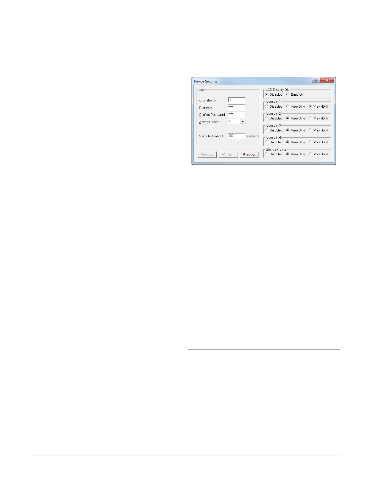
ROCLINK 800 Configuration Software User Manual (for FloBoss 107)
Field
Description
Password
entered in the previous field.
User Table Click an operator ID in the table. The Device Security
dialog box displays.
Figure 3-16. Device Security
Use this dialog box to edit the security on an existing
operator ID. To add an operator ID, click on an
empty cell in the table. The Device Security dialog
box displays. Complete the dialog box as described
below. To delete an operator ID, click a cell in that
line. When the Device Security dialog box appears,
click Remove. Answer Yes to the confirmation dialog
box that displays. ROCLINK 800 removes the
operator ID from the table.
Operator ID Sets the three alphanumeric
characters for the operator ID,
which is typically the initials of the
person who operates the device
through that communications port.
The operator ID is case-sensitive.
Each operator ID must be unique.
Password Sets the four numeric characters
between 0000 and 9999 for the
password. More than one operator
ID can have the same password.
Confirm
Access Level Sets the access permitted to this
Validates the password you
operator ID. Click to display all
options. 0 is the lowest access
level and allows access to the
fewest number of screens. 5 is the
highest access level and permits
access to all screens. Each access
level permits access to screens at
that level and any inherited from
lower access levels. For example,
the IDs with access level 3 can
access screens with levels 0, 1, 2,
and 3. Refer to Security Access
Levels.
3-32 Communications and Security Revised August-2020

ROCLINK 800 Configuration Software User Manual (for FloBoss 107)
User Access
Field Description
Security
Timeout
LCD Display
ON
User List 1 to
User List 4
Standard Lists Sets the user's access to the
Security On… Enables security for each comm port. Valid values
are:
Disabled Accepts all login requests. This is
User ID
Enabled:
Level Enabled
Sets, in seconds, the amount of
time the communication port waits
for a valid message before logging
you off of the device. Valid values
must be between 60 and 65535.
The default is 600.
Notes:
You must enable security on
each communication port
(Security On..) before the
Security Timeout is enabled for
that port.
Select Enabled to turn the LCD
Display Always ON and leave it
active, or select Disabled to allow
the LCD Display to time out and
turn itself off. If Enabled, the LCD
remains on until the next user logs
on who has the LCD Disabled.
Sets the user's access to LCD
User Lists 1, 2, 3, and 4 when
logging on to the FloBoss 107
through the LCD Touchpad. Valid
values are Disabled, View Only,
and View+Edit.
standard options when logging on
to the FloBoss 107 through the
LCD Touchpad. Valid values are
Disabled, View Only, and
View+Edit.
the default.
Accepts login requests if the user
(operator) ID and password are
valid. On successful login, full
access is allowed (access level 5).
Accepts login requests if the user
(operator) ID and password are
valid. Upon successful login, the
user is restricted by access level.
Refer to Security Access Levels.
Revised August-2020 Communications and Security 3-33
When you are finished, click Apply and then click OK to exit the screen.

ROCLINK 800 Configuration Software User Manual (for FloBoss 107)
[This page is intentionally left blank.]
3-34 Communications and Security Revised August-2020

ROCLINK 800 Configuration Software User Manual (for FloBoss 107)
Chapter 4 – The File Menu
In This Chapter
4.1 New Configuration ................................................................................... 4-2
4.1.1 Configuration Checklist .............................................................. 4-2
4.1.2 Duplicating a Configuration ........................................................ 4-2
4.1.3 Creating a New Configuration File ............................................. 4-3
4.2 Opening a Configuration File ................................................................... 4-6
4.2.1 Configuration Tree Menu ............................................................ 4-7
4.2.2 Modifying an Existing Configuration File .................................... 4-9
4.3 Downloading a Configuration .................................................................. 4-9
4.4 Saving a ROC User File ........................................................................ 4-10
4.5 Saving a Configuration .......................................................................... 4-11
4.5.1 Print Configuration .................................................................... 4-11
4.6 Print ....................................................................................................... 4-12
4.7 Print Setup ............................................................................................. 4-12
4.8 Recent Files ........................................................................................... 4-13
4.9 Close ..................................................................................................... 4-13
4.10 Exit ......................................................................................................... 4-13
Use the File menu options to print, open, close, and save configuration
files.
Figure 4-1. File Menu
Revised August-2020 File Menu 4-1

ROCLINK 800 Configuration Software User Manual (for FloBoss 107)
4.1 New Configuration
You configure a FloBoss either by modifying an existing configuration
file or by starting a new configuration file.
The full configuration procedure involves using the menu functions or
Configuration Tree Menu to access the configuration screens. Some of
the configuration screens may not be required for your application or may
not be available for your type of FloBoss.
The following checklists present the order of configuration in a typical
application. Omit configuration screens for modules and accessories that
do not appear in your hardware configuration and for control elements
(PID, FST, and such) that do not apply to your application.
4.1.1 Configuration Checklist
For a FloBoss 107:
ROC menu > ROCLINK 800 Security (logon)
Device Directory > Comm Port > Properties (PC communication
configurations)
ROC menu > Security (User List and Comm Port Security)
ROC menu > Clock
ROC menu > Information (system variables)
ROC menu > Comm Ports (FloBoss communication configurations)
Configure menu > I/O menu > AI, AO, DI, DO, MVS, DVS, PIM,
and PI
Meter menu > Setup
Configure menu > Control menu > PID Loop
Configure menu > Control menu > FST Registers
Configure menu > History Points
Utilities menu > FST Editor
View menu > Display > New or from File (for custom PC displays)
ROC menu > Flags (for saving and system variables to Flash
memory)
4.1.2 Duplicating a Configuration
You can duplicate the configuration for another FloBoss by using these
menu functions in the following order:
1. File > Save Configuration to save a device’s configuration to a
specified file.
2. ROC > Direct Connect (Local Port) or Connect (modem) to connect
physically to the second unit, and then communicate.
3. File > Download loads the configuration into the unit.
4-2 File Menu Revised August-2020

ROCLINK 800 Configuration Software User Manual (for FloBoss 107)
After you have loaded configuration data into the second FloBoss (Step
3) and changed it as needed, you can save the configuration to its own
disk file by using Step 1.
4.1.3 Creating a New Configuration File
The New Configuration File screen allows you to create a configuration
file off-line with the basic information about the meters and modules that
will be installed on the FloBoss for which the new configuration was
created.
1. Select File > New. The New Configuration File screen displays.
Figure 4-2. New File Configuration
2. Select FB107 from the File Type frame. The lower portion of the
New File Configuration screen changes to reflect the FB107.
Note: As you define the modules and place them in slots on the FB107,
additional fields appear on the New Configuration File. Figure 43 shows a sample completed configuration
Revised August-2020 File Menu 4-3

ROCLINK 800 Configuration Software User Manual (for FloBoss 107)
Field
Description
FB107.
Figure 4-3. New File Configuration (completed)
3. Review and complete the following fields:
File Type Associates the file type with a specific device. Select
FB107 to build an off-line configuration file for the
Control
Configuration
History Sizing Selects the maximum number of history point s in
Indicates the number of PID loops, FSTs, and Met er
Runs (AGAs) for the configuration.
Note: Activate only the necessary number of
devices for your device.
Standard and Extended History (History Sizing).
Caution: Select this value carefully: you cannot later
add History Points without first clearing
current history present in the unit.
Standard History archives up to 100 points of
minimum/maximum (min/max), minute, hourly,
and daily values. The min/max values are from
today and yesterday; the minute values are from
the last 60 minutes; hourly values are from the
last 35 days; and daily values are from the last
35 or 60 days.
Extended History can be configured to archive
up to 25 points of user-selectable values, from 1
second to 60 minute periods. Extended History
archiving provides a monitoring resolution for t he
FloBoss that is similar to a chart recorder or data
logger.
4-4 File Menu Revised August-2020

ROCLINK 800 Configuration Software User Manual (for FloBoss 107)
Indicates the type and number of modules you can
Integral Sensor
DVS
PIM
Field Description
Modules
I/O Configuration Sets the configuration of I/O points for either a 6
250 Ohm Resistor
Installed
install in the FB107.: Click to display valid choices.
On-Board No I/O – CPU does not have an I/O
assembly installed. Available only for slot 0.
On-Board 6-Pt I/O – CPU has an I/O assembly
installed. Available only for slot 0.
None – No module is installed in the slot.
RS-232 – Slot has an RS-232 communications
module installed. Available only for slot 1 or 2.
RS-485 – Slot has an RS-485 communications
module installed. Available only for slot 1 or 2.
MVS – Slot has an MVS module installed.
Aux 6-Pt I/O – Slot has an I/O module installed.
Note: FB107 modules are slot-specific. As you
define the type and location of modules,
ROCLINK 800 displays only those modules
available for installation in any slot. .
point CPU I/O assembly (On-Board 6 Point IO) or I/ O
module (Auxiliary 6 Point IO).
Note: This option displays only if you select the I/O
module.
Sets, for analog inputs, whether the module support s
4–20 mA or 0–5 V dc.
Valid values are Yes (250 ohm resistor is installed
and input uses 4–20 mA current) or No ( 250 ohn
resistor is not installed and input uses 0–5 V dc
current). The default is Yes.
4. Once you have completed the configuration, click Start. The Save As
dialog box displays.
5. Enter a file name for the configuration file. Configuration files for
ROCLINK 800 use the extension .800.
6. Click Save. ROCLINK 800 saves the new configuration file, and
displays the following dialog.
Displays the type of Integral Sensor installed in the
new configuration. Valid values are None, a Dual-
Variable Sensor (
), or Pulse Input Module (
).
Revised August-2020 File Menu 4-5

ROCLINK 800 Configuration Software User Manual (for FloBoss 107)
7. Click No to save the new configuration file and return to the New
Configuration File screen.
4.2 Opening a Configuration File
Use the Open option to open a configuration file stored on a PC’s hard
drive. Once you open the configuration file, it automatically becomes the
active configuration file and you may edit the file offline. You can also
load the configuration file into the device using the Download function.
To open a configuration file:
1. Start ROCLINK 800.
2. Select File > Open. The Open dialog box displays.
3. Select a configuration file name and click Open.The configuration
file displays.
Notes:
ROCLINK 800 files have the .800 extension.
If you receive an error when opening a configuration file, ensure
that your PC’s Regional Settings are configured correctly. Refer
to Installing ROCKLINK 800 under Microsoft 10, 8 or Windows 7
(located in Chapter 1).
4-6 File Menu Revised August-2020
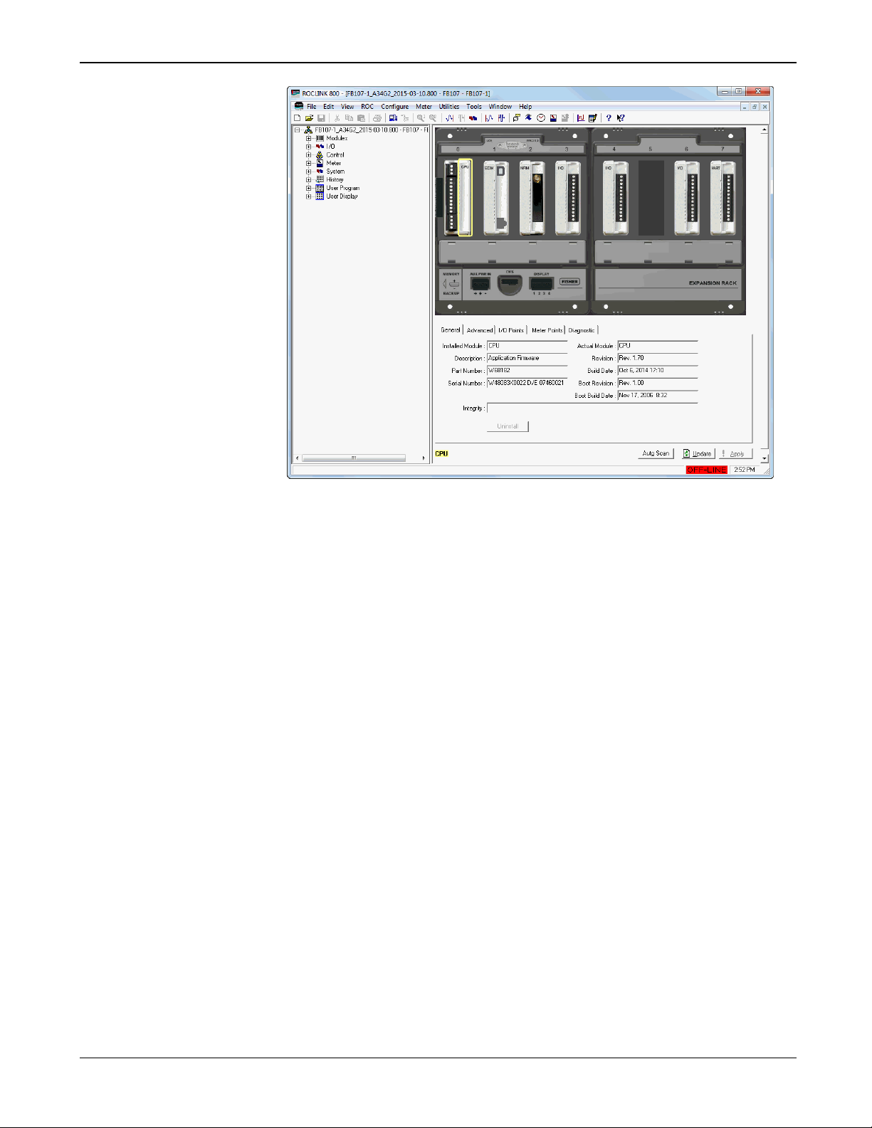
ROCLINK 800 Configuration Software User Manual (for FloBoss 107)
Figure 4-4. Open File Configuration
4.2.1 Configuration Tree Menu
When you open a configuration file, the Configuration Tree appears on
the left-hand side of the screen. The tree hierarchically displays the parts
of a configuration (such as I/O, Meter Runs, and History) that you can
change.
Revised August-2020 File Menu 4-7

ROCLINK 800 Configuration Software User Manual (for FloBoss 107)
Option
Description
I/O
Lists all available inputs and outputs by type.
Control
Displays the FST, Radio Control, Sampler/Odo rizer,
Information screen.
Meter
Lists all available gas meters and all stations.
System
Displays Comm Port, Device Flags, and Opcode Table
information.
History
Displays all available History Segments and History
Points.
User Program
Displays all user programs.
User Display
Accesses custom displays stored in the configuratio n
custom user displays and user program displays).
Figure 4-5. Configuration Tree Menu
DS800, and PID options enabled on the ROC >
file. The file can store a maximum of 246 displays (both
From the Configuration Tree, you may change the configuration or
monitor current operations. Once you are in the Configuration Tree menu,
you can use the + and – symbols to display or hide various options.
Double-click the desired function in the Configuration Tree to display the
associated screen. Double-clicking an icon is the same as sel e cting the
option in the menu bar or clicking a Toolbar button.
4-8 File Menu Revised August-2020

ROCLINK 800 Configuration Software User Manual (for FloBoss 107)
4.2.2 Modifying an Existing Configuration File
You can make modifications to an existing configuration file offline. This
allows you to share configuration files between multiple devices and
customize each configuration file to account for device differences.
To modify an existing configuration file:
1. Start ROCLINK 800.
2. Select File > Open. The Open dialog box displays.
3. Select a configuration file name and click Open. The configuration
file displays.
Note: ROCLINK 800 files have the .800 extension.
Figure 4-6. Modifying Configuration File
4.3 Downloading a Configuration
Use the Download option to download a saved configuration to a FloBoss
device. You create configuration files using File > New Configuration.
To download a saved configuration file:
1. Connect to the FloBoss.
2. Select File > Download. The Select File to Download dialog box
displays.
3. Select the configuration file name. ROCLINK 800 files have the
extension .800.
Revised August-2020 File Menu 4-9
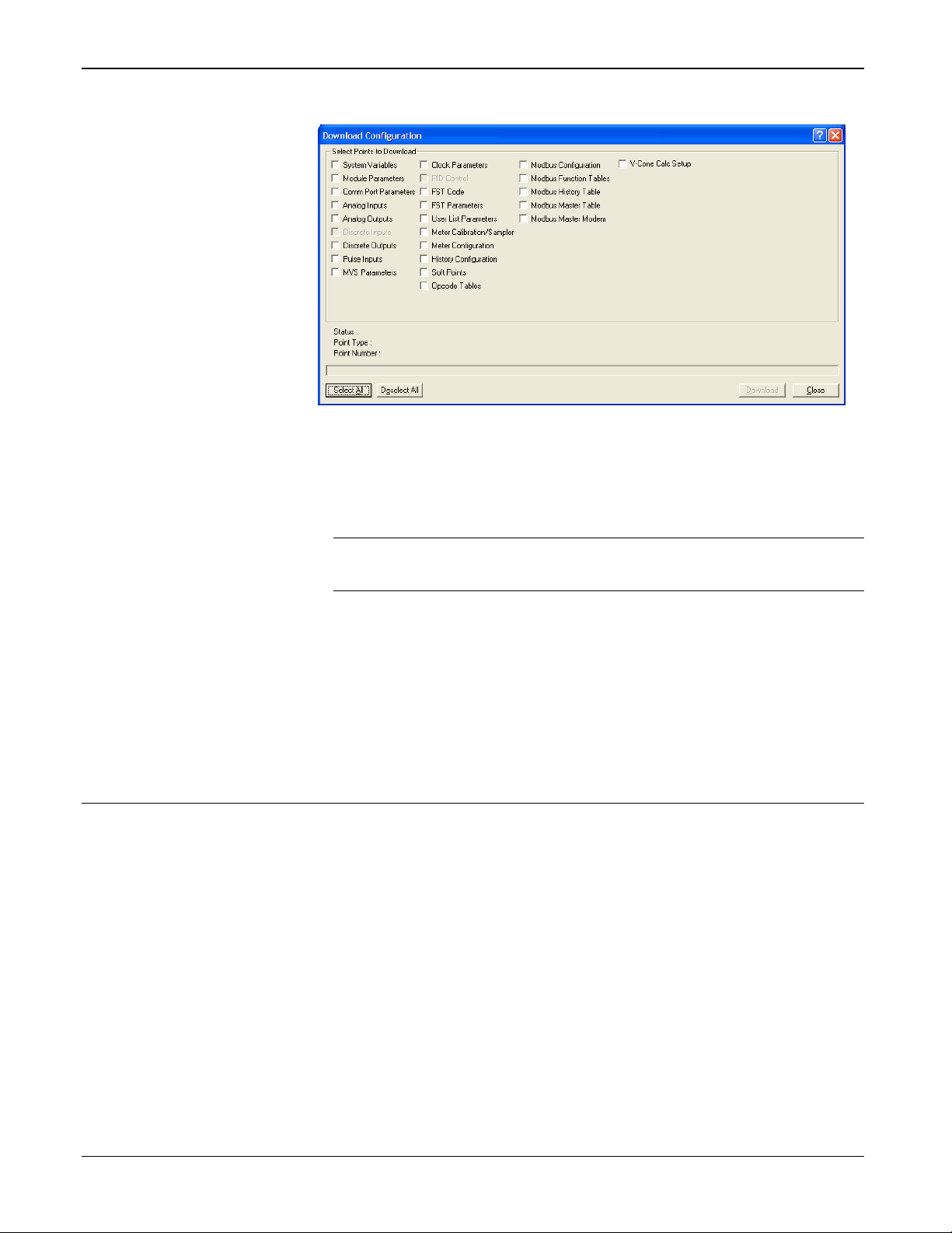
ROCLINK 800 Configuration Software User Manual (for FloBoss 107)
4. Click Open. The Download Configuration screen displays.
Figure 4-7. Download Configuration
5. Select only the Configuration Points you desire to download.
ROCLINK 800 grays out any items not configured in your
configuration.
Note: Once you select a point, ROCLINK 800 activates the
6. Click Download. ROCLINK 800 begins to download the
configuration points you have chosen, and displays the status, point
type, and point number information as the download progresses.
7. Click OK when the download completes.
8. Select ROC > Flags and click the Save Configuration for Flash
Memory button.
4.4 Saving a ROC User File
In addition to keeping backup copies of the configuration file, it is also
good practice to keep a backup copy of the ROC_USER.mdb file. This
file contains the communications, security, and password settings for the
FloBoss.
To create a backup copy of the file:
1. Open Windows Explorer and navigate to the folder where ROCLINK
800 software is located. Typically, this folder is C:\Program
Files\ROCLINK800.
Download button.
2. Create a copy of the ROC_USER.mdb file.
3. Paste the copy into another folder on the PC or a disk.
4-10 File Menu Revised August-2020
 Loading...