

Remote Automation Solutions ROCLINK 800 Configuration Software User Manual Manuals & Guides
Page 1

Form A6121
Part Number D301159X012
December 2005
ROCLINK™ 800 Configuration Software
User Manual
Flow Computer Division
Website: www.EmersonProcess.com/flow
Page 2

ROCLINK 800 User Manual
Revision Tracking Sheet
December 2005
This manual is periodically altered to incorporate new or updated information. The date revision level of
each page is indicated at the bottom of the page opposite the page number. A major change in the
content of the manual also changes the date of the manual, which appears on the front cover. Listed
below is the date revision level of each page.
Page Revision
All Pages Dec-05
All Pages Feb-05
All Pages Oct-04
All Pages Apr-04
All Pages Sep-03
All Pages Jul-03
All Pages Sep-02
FloBoss and ROCLINK are marks of one of the Emerson Process Management companies. The Emerson logo is a trademark
and service mark of Emerson Electric Co. All other marks are the property of their respective owners.
This product may be covered unde r pen di n g pat ent a ppl i cat i ons.
© Fisher Controls International, LLC. 2002-2005. All rights reserved.
Printed in the U.S.A.
While this information is presented in good faith and believed to be accurate, Fisher Controls does not guarantee satisfactory
results from reliance upon such information. Nothing contained herein is to be construed as a warranty or guarantee, express
or implied, regarding the performance, merchantability, fitness or any other matter with respect to the pro ducts, nor as a
recommendation to use any product or process in conflict with any patent. Fisher Controls reserves the right, without notice,
to alter or improve the designs or specifications of the products described herein.
Rev. Dec-05 ii
Page 3

ROCLINK 800 User Manual
TABLE OF CONTENTS
Section 1 – ROCLINK 800 Software Basics...............................................................1-1
1.1 ROCLINK 800 SOFTWARE DESCRIPTION ......................................................................................1-1
1.2 C
1.3 C
1.4 SOFTWARE INSTALLATION..............................................................................................................1-2
1.5 STARTING ROCLINK 800 SOFTWARE ...........................................................................................1-4
1.6 USER INTERFACE BASICS................................................................................................................1-6
1.7 CONFIGURATION BASICS ..............................................................................................................1-14
1.8 CREATING A NEW CONFIGURATION FILE......................................................................................1-18
OMPUTER REQUIREMENTS............................................................................................................1-2
ONTACTING THE FLOW COMPUTER DIVISION...............................................................................1-2
1.4.1 Manually Creating a Desktop Shortcut ..................................................................................1-3
1.4.2 Launching ROCLINK 800 During Setup...............................................................................1-4
1.4.3 Un-Installing ROCLINK 800.................................................................................................1-4
1.5.1 Logging On.............................................................................................................................1-5
1.6.1 Menu Bar and Menus.............................................................................................................1-8
1.6.2 Buttons....................................................................................................................................1-8
1.6.3 ToolBar...................................................................................................................................1-9
1.6.4 Keystrokes............................................................................................................................1-10
1.6.5 Help System .........................................................................................................................1-11
1.6.6 About ROCLINK 800 ..........................................................................................................1-12
1.6.7 Basic Navigation ..................................................................................................................1-12
1.6.8 TLP Box Selections..............................................................................................................1-13
1.6.9 AutoScan Update Interval Option........................................................................................1-14
1.7.1 Configuration Checklist (ROC800-Series) ..........................................................................1-15
1.7.2 Configuration Checklist (ROC300-Series) ..........................................................................1-16
1.7.3 Configuration Checklist (FloBoss 100-Series).....................................................................1-16
1.7.4 Configuration Checklist (FloBoss 407)................................................................................1-17
1.7.5 Duplicating a Configuration.................................................................................................1-17
1.8.1 Opening a Configuration File...............................................................................................1-19
1.8.2 Configuration Tree Menu.....................................................................................................1-20
Section 2 – Configuring Communications and Security ........................................... 2-1
2.1 S
2.2 ROCLINK
2.3 DEVICE SECURITY...........................................................................................................................2-6
2.4 L
2.5 D
2.6 ROCLINK 800 COMMUNICATIONS..............................................................................................2-17
Rev. Dec-05 Table of Contents iii
ECURITY ACCESS LEVELS .............................................................................................................2-2
800 SECURITY..............................................................................................................2-5
2.3.1 Device Security – Users (ROC800-Series and FloBoss 100-Series).....................................2-6
2.3.2 Device Security – Users (FloBoss 407) .................................................................................2-8
2.3.3 Device Security – Users (ROC300-Series)............................................................................2-9
2.3.4 Device Security – Groups.....................................................................................................2-10
2.3.5 Device Security – Comm Ports (ROC800-Series and FloBoss 100-Series) ........................2-11
2.3.6 Device Security – Users / Group Summary (ROC800-Series) ............................................2-12
ICENSE KEY ADMINISTRATOR (ROC800-SERIES) ......................................................................2-13
EVICE DIRECTORY......................................................................................................................2-14
2.5.1 Device Root..........................................................................................................................2-15
2.6.1 ROCLINK 800 Communications – General........................................................................2-17
2.6.2 ROCLINK 800 Communications – Advanced.....................................................................2-20
Page 4

ROCLINK 800 User Manual
2.7 COMMUNICATION PORTS ON THE ROC AND FLOBOSS .................................................................2-21
2.7.1 Comm Ports – General.........................................................................................................2-25
2.7.2 Comm Ports – Modbus Host Parameters (FloBoss 407 and ROC300-Series).....................2-27
2.7.3 Comm Ports – Modem .........................................................................................................2-28
2.7.4 Comm Ports – SRBX or RBX..............................................................................................2-30
2.7.5 Comm Ports – Store & Forward (ROC800-Series and FloBoss 407)..................................2-32
2.7.6 Comm Ports – Diagnostics (ROC800-Series)......................................................................2-33
2.7.7 Configuring TCP/IP Communications on the Ethernet Port (ROC800-Series)...................2-34
2.8 CONNECTING TO A ROC OR FLOBOSS ..........................................................................................2-36
2.8.1 Direct Connect......................................................................................................................2-36
2.8.2 Local Operator Interface (LOI – Local Port) .......................................................................2-37
2.8.3 Connect.................................................................................................................................2-37
2.8.4 Successful Login ..................................................................................................................2-37
2.9 TROUBLESHOOTING COMMUNICATIONS .......................................................................................2-38
2.9.1 Troubleshooting Connection Errors.....................................................................................2-38
2.9.2 Troubleshooting ROCLINK 800 Communications .............................................................2-39
2.9.3 Troubleshooting TCP/IP Connections..................................................................................2-39
2.9.4 Communications Monitor.....................................................................................................2-40
2.9.5 Disconnecting from a ROC or FloBoss................................................................................2-40
Section 3 – Configuring System Parameters..............................................................3-1
3.1 SETTING THE CLOCK.......................................................................................................................3-1
3.2 CONFIGURING DEVICE INFORMATION.............................................................................................3-2
3.2.1 Information – General............................................................................................................3-4
3.2.2 Information – Internet (ROC800-Series) ...............................................................................3-6
3.2.3 Information – Points...............................................................................................................3-7
3.2.4 Information – Other Information..........................................................................................3-10
3.2.5 Information – System Configuration (ROC800-Series).......................................................3-12
3.2.6 Information – Revision Info (FloBoss 100-Series)..............................................................3-13
3.2.7 Information – Keypad Display (ROC800-Series)................................................................3-14
3.3 C
ONFIGURING SYSTEM FLAGS ......................................................................................................3-15
3.3.1 Returning the Device to Factory Default Settings................................................................3-18
3.3.2 Flags – Advanced.................................................................................................................3-19
3.3.3 Flags – User Programs (FloBoss 100-Series, ROC300-Series, and FloBoss 407) ..............3-22
Section 4 – Configuring Inputs and Outputs (I/O).................................................... 4-1
4.1 I/O C
4.2 AI – A
4.2.1 AI – General...........................................................................................................................4-2
4.2.2 AI – Advanced........................................................................................................................4-4
4.2.3 AI – Alarms............................................................................................................................4-7
4.3 AO – ANALOG OUTPUT CONFIGURATION.......................................................................................4-9
4.3.1 AO – General..........................................................................................................................4-9
4.3.2 AO – Advanced....................................................................................................................4-11
4.3.3 AO – Alarms (ROC800-Series) ...........................................................................................4-13
ONFIGURATION OVERVIEW ....................................................................................................4-1
NALOG INPUT CONFIGURATION............................................................................................4-2
Rev. Dec-05 Table of Contents iv
Page 5

ROCLINK 800 User Manual
4.4 DI – DISCRETE INPUT CONFIGURATION........................................................................................4-14
4.4.1 DI – General.........................................................................................................................4-14
4.4.2 DI – Advanced......................................................................................................................4-16
4.4.3 DI – TDI Parameters (FloBoss 407 and ROC300-Series) ...................................................4-18
4.4.4 DI – Alarms..........................................................................................................................4-19
4.5 DO – DISCRETE OUTPUT CONFIGURATION...................................................................................4-21
4.5.1 DO – General........................................................................................................................4-22
4.5.2 DO – Advanced....................................................................................................................4-24
4.5.3 DO – TDO Parameters.........................................................................................................4-26
4.5.4 DO – Alarms (ROC800-Series) ...........................................................................................4-28
4.6 PI – PULSE INPUT CONFIGURATION..............................................................................................4-29
4.6.1 PI – General..........................................................................................................................4-29
4.6.2 PI – Advanced......................................................................................................................4-32
4.6.3 PI – Alarms...........................................................................................................................4-35
4.7 P
4.8 RTD – RTD I
4.9 TC – THERMOCOUPLE INPUT CONFIGURATION (ROC800-SERIES) ..............................................4-42
4.10 SYSTEM AI – SYSTEM ANALOG INPUT CONFIGURATION (ROC800-SERIES)................................4-46
4.11 HART INPUT CONFIGURATION (ROC800-SERIES).......................................................................4-50
4.12 MVS S
ULSE INTERFACE MODULE DIAGNOSTIC (FLOBOSS 104)............................................................4-37
NPUT CONFIGURATION (ROC800-SERIES) .............................................................4-38
4.8.1 RTD – General .....................................................................................................................4-39
4.8.2 RTD – Advanced..................................................................................................................4-40
4.8.3 RTD – Alarms......................................................................................................................4-41
4.9.1 Thermocouple – General......................................................................................................4-43
4.9.2 Thermocouple – Advanced ..................................................................................................4-44
4.9.3 Thermocouple – Alarms.......................................................................................................4-45
4.10.1 System AI – General (ROC800-Series) ...............................................................................4-47
4.10.2 System AI – Advanced (ROC800-Series)............................................................................4-48
4.10.3 System AI – Alarms (ROC800-Series)................................................................................4-49
4.11.1 HART – General (ROC800-Series) .....................................................................................4-51
4.11.2 HART – Advanced (ROC800-Series)..................................................................................4-53
4.11.3 HART – Device (ROC800-Series).......................................................................................4-54
ENSOR (ROC800-SERIES OR FLOBOSS 407)......................................................................4-57
Section 5 – Configuring the Meter Setup....................................................................5-1
5.1 M
5.2 STATION CONFIGURATION (ROC800-SERIES)................................................................................5-2
5.3 METER SETUP CONFIGURATION....................................................................................................5-11
Rev. Dec-05 Table of Contents v
ETER SETUP BASICS.....................................................................................................................5-1
5.2.1 Station – General (ROC800-Series).......................................................................................5-3
5.2.2 Station – Gas Quality (ROC800-Series) ................................................................................5-5
5.2.3 Station – Advanced (ROC800-Series) ...................................................................................5-7
5.2.4 Station – Alarms (ROC800-Series)........................................................................................5-9
5.3.1 Meter – General....................................................................................................................5-12
5.3.2 Meter – Inputs ......................................................................................................................5-16
5.3.3 Meter – Gas Quality (FloBoss 100-Series, ROC300-Series, and FloBoss 407)..................5-19
5.3.4 Meter – Advanced................................................................................................................5-21
5.3.5 Meter – Sampler (FloBoss 100-Series)................................................................................5-32
5.3.6 Meter – Instrument Calibration (FloBoss 100-Series).........................................................5-33
Page 6

ROCLINK 800 User Manual
5.3.7 Meter – Calibration Factors (ROC800-Series).....................................................................5-34
5.3.8 Meter – Alarms.....................................................................................................................5-35
5.3.9 Meter – Mass Meter Pressure Effect (ROC800-Series).......................................................5-38
Section 6 – Configuring and Viewing History............................................................ 6-1
6.1 H
6.2 HISTORY SETUP (FLOBOSS 100-SERIES).........................................................................................6-3
6.3 HISTORY SETUP (ROC300-SERIES AND FLOBOSS 407)..................................................................6-6
6.4 CONFIGURING HISTORY SEGMENTS (ROC800-SERIES)..................................................................6-8
6.5 CONFIGURING HISTORY POINTS ....................................................................................................6-10
6.6 CONFIGURING HISTORY FOR EFM REPORTING.............................................................................6-13
6.7 EFM R
6.8 H
6.9 DEVICE MEMORY..........................................................................................................................6-35
ISTORY .........................................................................................................................................6-1
6.2.1 Configuring FloBoss 100-Series History...............................................................................6-5
EPORTS..............................................................................................................................6-17
6.7.1 Collecting ROC Data............................................................................................................6-17
6.7.2 Displaying EFM Reports......................................................................................................6-18
6.7.3 Converting EFM Files..........................................................................................................6-19
6.7.4 PGAS Conversions...............................................................................................................6-23
6.7.5 Flow-Cal (.CFX) Conversions .............................................................................................6-31
ISTORY, ALARM, AND EVENT LOG REPORTS..............................................................................6-31
6.8.1 Viewing the History Log......................................................................................................6-31
6.8.2 Viewing the Alarm Log........................................................................................................6-31
6.8.3 Viewing the Event Log.........................................................................................................6-31
6.8.4 Viewing Report Logs From the Device ...............................................................................6-32
6.8.5 Viewing Report Logs From a File........................................................................................6-33
6.8.6 Viewing the History Log Report Graphically (Plot)............................................................6-34
Section 7 – Extended Functions...................................................................................7-1
7.1 SOFT POINTS...................................................................................................................................7-1
7.2 OPCODE TABLE...............................................................................................................................7-3
7.3 SAMPLER/ODORIZER (ROC800-SERIES).........................................................................................7-4
7.4 P
7.5 RADIO POWER CONTROL ..............................................................................................................7-18
7.6 DS800 DEVELOPMENT SUITE SOFTWARE (ROC800-SERIES).......................................................7-21
7.7 U
7.8 USER DATA...................................................................................................................................7-25
ROPORTIONAL, INTEGRAL, AND DERIVATIVE (PID) .....................................................................7-5
7.4.1 PID (ROC800-Series and FloBoss 100-Series)......................................................................7-6
7.4.2 PID (ROC300-Series and FloBoss 407).................................................................................7-8
7.4.3 PID – General.........................................................................................................................7-9
7.4.4 PID – Tuning........................................................................................................................7-13
7.4.5 PID – Status (ROC800-Series).............................................................................................7-16
7.4.6 PID – Example .....................................................................................................................7-17
SER PROGRAM ADMINISTRATOR ................................................................................................7-22
7.7.1 User Program Download Steps ............................................................................................7-24
Rev. Dec-05 Table of Contents vi
Page 7

ROCLINK 800 User Manual
Section 8 – Modbus Communications.........................................................................8-1
8.1 M
8.2 MODBUS CONFIGURATION – HISTORY............................................................................................8-8
8.3 M
8.4 MODBUS REGISTERS (ROC800-SERIES AND FLOBOSS 100-SERIES) ............................................8-18
8.5 MODBUS MASTER TABLE (ROC800-SERIES) ...............................................................................8-29
8.6 MODBUS MASTER MODEM (ROC800-SERIES).............................................................................8-31
8.7 MODBUS HOST PARAMETERS (FLOBOSS 407 AND ROC300-SERIES)...........................................8-32
Section 9 – Saving and Retrieving Configurations....................................................9-1
9.1 SAVING A ROC USER FILE .............................................................................................................9-1
9.2 SAVING A CONFIGURATION.............................................................................................................9-2
9.3 DOWNLOADING A CONFIGURATION ................................................................................................9-3
ODBUS CONFIGURATION (ROC800-SERIES AND FLOBOSS 100-SERIES).....................................8-2
8.1.1 Configuring a ROC800-Series or FloBoss 100-Series as a Modbus Slave............................8-2
8.1.2 Configuring a ROC800-Series as a Modbus Host..................................................................8-2
8.1.3 Modbus Configuration – General...........................................................................................8-3
8.1.4 Modbus Configuration – Scale Values...................................................................................8-5
8.2.1 Modbus Configuration – History Access Registers (FloBoss 100-Series) ..........................8-10
ODBUS EVENTS AND ALARMS FUNCTIONALITY.........................................................................8-13
8.3.1 Modbus Events and Alarms (ROC800-Series) ....................................................................8-14
8.3.2 Reading Modbus Events and Alarms Register.....................................................................8-15
8.3.3 Acknowledging Modbus Events and Alarms.......................................................................8-16
8.4.1 Modbus Conversion (ROC800-Series and FloBoss 100-Series) .........................................8-23
9.3.1 Opening a Configuration........................................................................................................9-4
Section 10 – Calibration..............................................................................................10-1
10.1 CALIBRATION BASICS ...................................................................................................................10-1
10.1.1 Calibration Report................................................................................................................10-2
10.2 STARTING CALIBRATION...............................................................................................................10-3
10.2.1 Verify – Calibration............................................................................................................10-3
10.2.2 Set Zero – Calibration.........................................................................................................10-5
10.2.3 Set Span – Calibration ........................................................................................................10-7
10.2.4 Set Midpoints – Calibration................................................................................................10-8
10.2.5 Zero Shift / Offset / RTD Bias – Calibration....................................................................10-10
10.2.6 Orifice Meter Calibration.................................................................................................. 10-10
10.2.7 Turbine Meter Calibration ................................................................................................10-13
10.2.8 AI and RTD Calibration....................................................................................................10-14
10.2.9 HART Calibration.............................................................................................................10-15
10.3 ANALOG INPUT CALIBRATION VALUES ......................................................................................10-16
10.4 RTD I
10.5 MVS INPUT CALIBRATION VALUES (ROC800-SERIES AND FLOBOSS 407) ...............................10-19
NPUT CALIBRATION VALUES ............................................................................................10-17
Section 11 – Updates and Changes............................................................................11-1
11.1 UPDATE FIRMWARE ......................................................................................................................11-1
11.1.1 Update Firmware – I/O Termination Board........................................................................11-3
11.1.2 Update Firmware – Keypad Display (ROC800-Series)......................................................11-4
11.2 UPGRADE HARDWARE (FLOBOSS 100-SERIES).............................................................................11-5
11.3 P
LATE CHANGE.............................................................................................................................11-6
Rev. Dec-05 Table of Contents vii
Page 8

ROCLINK 800 User Manual
Section 12 – Displays, Diagnostics, and Monitoring................................................12-1
12.1 P
12.2 I/O M
12.3 LCD D
12.4 LCD U
12.5 METER RUN VALUES ....................................................................................................................12-7
12.6 C
12.7 K
RINT CONFIGURATION.................................................................................................................12-2
ONITOR................................................................................................................................12-3
ISPLAY CONFIGURATION (ROC300-SERIES).....................................................................12-5
SER LIST (FLOBOSS 100-SERIES AND FLOBOSS 407)........................................................12-6
USTOM DISPLAYS .......................................................................................................................12-9
12.6.1 Custom Displays – New Display.....................................................................................12-10
12.6.2 Custom Displays – Objects .............................................................................................12-11
12.6.3 Custom Displays – Object Properties..............................................................................12-12
12.6.4 Editing a Custom Display From a File............................................................................12-13
12.6.5 Adding an Expression to a Custom Display Object........................................................12-13
12.6.6 Display Administrator.....................................................................................................12-15
EYPAD DISPLAY EDITOR CONFIGURATION...............................................................................12-16
12.7.1 Creating a New Keypad Display File (ROC800-Series).................................................12-16
12.7.2 Update Keypad Display Firmware (ROC800-Series).....................................................12-17
12.7.3 Editing a Keypad Display File ........................................................................................12-18
12.7.4 Keypad Display Security (ROC800-Series)....................................................................12-19
Appendix A – FST Editor............................................................................................ A-1
A.1 FST EDITOR...................................................................................................................................A-1
A.2 FUNCTION SEQUENCE TABLE INTRODUCTION................................................................................A-1
A.3 FST REGISTERS .............................................................................................................................A-3
A.4 FST EDITOR...................................................................................................................................A-5
A.4.1 FST Function Structure .........................................................................................................A-6
A.4.2 FST Label Field.....................................................................................................................A-7
A.4.3 FST Command Field – CMD................................................................................................A-7
A.4.4 FST Argument Fields – ARG................................................................................................A-7
A.4.5 FST Comment Fields.............................................................................................................A-8
A.4.6 FST Function Examples........................................................................................................A-8
A.4.7 Basic Rules for Creating FSTs..............................................................................................A-8
A.4.8 FST Storage and Restart........................................................................................................A-9
A.5 W
A.6 M
A.7 FST C
ORKING WITH FSTS..................................................................................................................A-10
A.5.1 Creating an FST...................................................................................................................A-10
A.5.2 Altering an FST – Edit Menu..............................................................................................A-13
ONITOR MODE ..........................................................................................................................A-13
A.6.1 FST – Trace Mode...............................................................................................................A-15
OMMAND LIBRARY............................................................................................................A-16
A.7.1 FST Mathematical Commands............................................................................................A-18
A.7.2 FST Logical Commands......................................................................................................A-20
A.7.3 FST Comparison Commands ..............................................................................................A-22
A.7.4 FST Time-Related Commands............................................................................................A-23
A.7.5 FST Control-Related Commands........................................................................................A-24
A.7.6 FST Miscellaneous Commands...........................................................................................A-25
A.7.7 FST Database Commands...................................................................................................A-26
Rev. Dec-05 Table of Contents viii
Page 9

ROCLINK 800 User Manual
Glossary.........................................................................................................................G-1
Index................................................................................................................................I-1
Rev. Dec-05 Table of Contents ix
Page 10

ROCLINK 800 User Manual
SECTION 1 – ROCLINK 800 SOFTWARE BASICS
This section describes how to use the ROCLINK 800 Configuration Software to configure and monitor
ROC800-Series Remote Operations Controllers, ROC300-Series, FloBoss 407 Flow Managers, and
FloBoss 100-Series devices.
The software runs on a personal computer that uses the Windows 98 or higher operating system. This
user manual covers configuration, calibration, monitoring, database archiving, custom displays, and
embedded utilities.
In this Chapter
Section Page
1.1 ROCLINK 800 Software Description............................................................................................. 1-1
1.2 Computer Requirements................................................................................................................. 1-2
1.3 Contacting the Flow Computer Division........................................................................................1-2
1.4 Software Installation.......................................................................................................................1-2
1.5 Starting ROCLINK 800 Software................................................................................................... 1-4
1.6 User Interface Basics ...................................................................................................................... 1-6
1.7 Configuration Basics..................................................................................................................... 1-14
1.8 Creating a New Configuration File...............................................................................................1-18
1.1 ROCLINK 800 Software Description
ROCLINK 800 Configuration Software provides the capability to monitor, configure, and calibrate
ROC800-Series Remote Operations Controllers, ROC300-Series, FloBoss 407 Flow Managers, and
FloBoss 100-Series Flow Managers. The software and user documentation are supplied on a CD-ROM.
ROCLINK 800 software is designed for ease of use. Drop-down menus simplify accessing the functions
provided by the software. Dialog boxes and drop-down list boxes help to direct selections and data
entry. You can perform actions with the keyboard or a pointing device, such as a mouse. Refer to User
Interface Basics for a description of the user interface.
Help screens are accessed either from the Help menu or in a context-sensitive fashion using <F1>. This
feature makes it easy to access on-line information for any ROCLINK 800 software topic.
You can build custom displays for the ROC or FloBoss that combines both graphic and dynamic data
elements. The displays can monitor the operation of the ROC or FloBoss either locally or remotely.
The software also provides multiple levels of security for controlling access to ROCLINK 800 software
functions, as well as the ROC database.
Note: If you are using a serial mouse (typically plugs into serial port COM1), be sure to set up
communications to the ROC or FloBoss through a port that does not share interrupts (typically
COM2), or a conflict occurs.
Rev. Dec-05 ROCLINK 800 Software Basics 1-1
Page 11

ROCLINK 800 User Manual
1.2 Computer Requirements
ROCLINK 800 software runs on most IBM-compatible personal computers (PCs). The PC can be a
desktop or a portable computer. In any case, the PC should meet the following minimum requirements:
♦ Pentium-class processor (233 MHz or greater recommended).
♦ CD-ROM drive.
♦ Windows 98, ME, NT 4.0 (Service Pack 6), 2000 (Service Pack 2), or XP.
♦ 64 MB of RAM (Random Access memory).
♦ SVGA color monitor, 800 by 600 pixels, small fonts.
♦ 15 to 50 MB of available hard disk space depending on Operating System and revision level.
♦ EIA-232 (RS-232) serial connection, a dial-up modem connection, a TCP/IP connection
(ROC800-Series), or a wireless radio (FloBoss 100-Series).
1.3 Contacting the Flow Computer Division
Please contact your local sales representative, or contact the Flow Computer Division directly.
Emerson Process Management
Flow Computer Division
Marshalltown, IA 50158 USA
Houston, TX 77065 USA
Pickering, North Yorkshire UK Y018 7JA
E-mail: fas.tech-support@emersonprocess.com
Website: www.emersonprocess.com/flow/
Technical Support Website: www.emersonprocess.com/flow/Emerson/support/support_index.html
Telephone: (641) 754-3449 (Monday through Friday 7:30 AM to 4:30 PM Central US Time)
1.4 Software Installation
To install ROCLINK 800 software:
1. Start the installation by one of the two methods described below.
♦ Method 1 – If you have a CD-ROM that contains the ROCLINK 800 installation files:
A. Place the ROCLINK Software Installation CD-ROM into your drive.
B. If the CD-ROM runs automatically, click the Install a ROCLINK Product button in the
Main Menu.
C. Click the Install ROCLINK 800 button in the Installation Screen.
Note: If the CD-ROM does not run automatically, click Windows Start > Run.
When the Run dialog box opens, click the Browse button and navigate to the CDROM drive and select Setup.exe. Click the Open button. If the CD-ROM drive is
drive D, the location will be D:\Installs\ROCLINK800_ W68130\Setup.exe. Click
OK in the Run dialog box.
Rev. Dec-05 ROCLINK 800 Software Basics 1-2
Page 12

ROCLINK 800 User Manual
♦ Method 2 – If you have .zip file that contains the ROCLINK 800 installation files:
A. Extract the .zip file to the local hard drive (for example, in the C:\TEMP\ directory).
B. Run setup.exe from extraction location (for example, run C:\TEMP\SETUP.EXE).
The Installation Wizard screen appears.
2. The Installation Wizard determines whether ROCLINK 800 has been installed previously.
♦ If this is an upgrade, a dialog box appears asking whether to continue with the upgrade. Click
Yes. Installation begins. Click Next when prompted.
♦ If this is a new installation, click Next in the ROCLINK 800 Welcome screen. Read the
License Agreement and click Yes to confirm. Enter your Name and Company name, and
click Next.
3. Select a destination folder, if you want to install the software in a folder other than the default,
C:\Program Files\ROCLINK800. The ROCLINK800 default folder is recommended.
4. Click Next.
A confirmation screen appears when you are ready to start copying files.
5. Click Next in the Setup Status screen.
6. Click the Finish button in the Wizard Complete screen.
7. If the installation was performed from the CD-ROM, select View Manual or Exit on the Main
Menu screen. Once you have exited the Main Menu, remove the installation CD-ROM.
Note: A restart may be necessary after installation is complete.
1.4.1 Manually Creating a Desktop Shortcut
ROCLINK 800 software installation should automatically create a Desktop Shortcut on your computer.
If for some reason you need to manually create the Desktop Shortcut, perform the following steps.
1. Double-click the My Computer icon.
2. Navigate to the C:\Program Files\ROCLINK800 folder or the folder where you installed
ROCLINK 800.
3. Select the ROCLINK.exe file.
4. Select Create Shortcut from the File menu.
5. Click and drag the shortcut to your Desktop.
6. Double-click the shortcut on your desktop to launch ROCLINK 800 software.
Rev. Dec-05 ROCLINK 800 Software Basics 1-3
Page 13

ROCLINK 800 User Manual
1.4.2 Launching ROCLINK 800 During Setup
This procedure launches ROCLINK 800 software every time you start this computer.
1. Double-click the My Computer icon.
2. Navigate to the C:\Program Files\ROCLINK800 folder or the folder where you installed
ROCLINK 800 software.
3. Select the ROCLINK.exe file.
4. Select File > Create Shortcut.
5. Depending on the Operating System of your PC, use the required method to place the shortcut
file into the startup folder.
1.4.3 Un-Installing ROCLINK 800
To remove ROCLINK 800 software from a personal computer, perform the following steps.
1. Click the Windows Start button.
2. Select Settings > Control Panel.
3. Double-click the Add/Remove Programs icon.
4. Select ROCLINK 800.
5. Click Add/Remove button.
6. Follow the instructions.
1.5 Starting ROCLINK 800 Software
To use ROCLINK 800 software to configure a hardware device, you must have the ROC or FloBoss
properly connected to power and I/O. Refer to the appropriate hardware instruction manual. Initially, the
ROC should also be connected to a personal computer (PC) running ROCLINK 800 using the Local
Operator Interface (LOI), serial, modem, or Ethernet port.
To run ROCLINK 800 software, perform one of the following steps:
♦ Double-click the Desktop shortcut.
♦ Select Start > Programs > ROCLINK 800 > ROCLINK 800.
♦ Double-click the file ROCLINK.exe located in C:\Program Files\Roclink800 (the default
directory), or wherever you installed ROCLINK 800 software.
The software loads and initializes.
Note: You can only run one version of ROCLINK 800 software at a time.
Rev. Dec-05 ROCLINK 800 Software Basics 1-4
Page 14

ROCLINK 800 User Manual
1.5.1 Logging On
To log on to ROCLINK 800 Software:
1. Connect the ROC or FloBoss to the Local Operator Interface (LOI – Local Port) and launch
ROCLINK 800.
Figure 1-1. Logon
2. Type in your assigned 3-character identifier in the User ID field and press <Enter> or <Tab>.
Note: This User ID is case sensitive.
Your initials are typically your User ID. If User IDs have not yet been assigned, try using the
default User ID. of LOI. User IDs are assigned by using the ROC > Security feature in
ROCLINK 800 software.
3. Type in your assigned 4-digit Password and press <Enter> or click OK. For added security, the
software displays an asterisk for each number that you type. If Passwords have not yet been
assigned, use the default Password of 1000 (valid with default User ID of LOI).
ROCLINK 800 software compares the entered User ID and Password to a list of valid ones.
If the log on is not valid, a dialog box appears. Click OK and re-enter the User ID and Password. You
can repeat the procedure as many times as needed until you successfully enter a valid User ID and
Password.
To exit from the log on screen, press <Esc> or click Cancel. This aborts ROCLINK 800 software and
returns you to the point where you started ROCLINK 800 software.
Rev. Dec-05 ROCLINK 800 Software Basics 1-5
Page 15

ROCLINK 800 User Manual
1.6 User Interface Basics
Users interact with ROCLINK 800 software using various displays on the computer monitor and the
computer keyboard and/or pointing device.
The major components of ROCLINK 800 software user interface are:
♦ Menu bar and menus.
♦ Toolbar.
♦ Function screens.
♦ Dialog boxes.
♦ Help system, including the Status bar and message boxes.
♦ Device Directory or Configuration Tree menu.
ROCLINK 800 software employs a Graphical User Interface (GUI) with a standard Windows menu
structure. After logging on to ROCLINK 800 software, available functions display in a menu bar with
drop-down menus. A Status Line at the bottom left of the display contains pertinent information about
the highlighted item, such as a menu option or a parameter.
Buttons display dialog boxes for further configuration details or perform a desired action, such as the
Update button. To activate the button:
♦ Click the button with a left click of the mouse.
♦ When a button is active, press <Enter> or a function key.
Dialog boxes are areas that “pop up” inside the current screen to allow further selections or values to be
entered. They can also provide messages or information that is more detailed.
The menu structure lists choices from which you can select the desired function. Once a function is
selected, the screen or dialog box for that function displays. This screen or dialog box provides the
requested information and lets you enter the applicable configuration data. Refer to Table 1-1.
Rev. Dec-05 ROCLINK 800 Software Basics 1-6
Page 16

ROCLINK 800 User Manual
Table 1-1. Menu Listing for ROCLINK 800
Menu Menu Options
File
Edit
View
ROC
New, Open…, Download…, Close, Save Configuration, Print Configuration, Print
1, 3, 4
Print Setup
1, 3, 4
Undo
, [List of recent files], Exit
1, 3, 4
, Cut
, Copy
Directory, EFM Report, Calibration Report, History, Alarms, Events, Display, I/O Monitor, Toolbar
Direct Connect, Connect, Collect Data, Clock, Security, Comm Ports, Memory
Flags
Configure
Meter
Utilities
I/O, Control, History Segments
LCD
4
, User Data
2, 3, 4
Setup, Calibration, Values, Plate Change, History
Update Firmware, Update Hardware
Program Administrator, ROCLINK 800 Security, AI Calibration Values, RTD Calibration Values
MVS Calibration Values
Tools
Window
Help
1. This option applies to ROC800-Series units.
2. This option applies to FloBoss 100-Series units.
3. This option applies to FloBoss 407 units.
4. This option applies to ROC300-Series units.
Customize, Options
Cascade, Tile, Device Directory, [List of open windows]
Help Topics, About ROCLINK 800
1, 3, 4
, Paste
1
, History Points, Opcode Table, MODBUS, LCD User List
1, 3
, FST Editor, ROC Keypad Display Editor
1, 3, 4
3, 4
2
, License Key Administrator1, Convert EFM File, User
1
, Communications Monitor
1, 3, 4
2, 3, 4
,
, Information,
2, 3
,
1
,
Rev. Dec-05 ROCLINK 800 Software Basics 1-7
Page 17

ROCLINK 800 User Manual
1.6.1 Menu Bar and Menus
The menu bar appears at the top of the screen.
From the menu bar, you can use either the keyboard or the mouse to activate a menu and then to select a
function in that menu. You can also select functions using ToolBar Buttons or the Configuration Tree
Menu.
Figure 1-2. Menu Bar and ToolBar (ROC800-Series Example)
1.6.2 Buttons
Several buttons appear on the majority of ROCLINK 800 screens.
Minimize and hide windows.
Maximize the size of the windows to fit in the screen area.
Return to Original size of the window.
Close a window.
Expand options listed in the Device Directory or Configuration Tree Menu.
Hide options listed in the Device Directory or Configuration Tree Menu.
Copy contents of window to Clipboard.
Rev. Dec-05 ROCLINK 800 Software Basics 1-8
Page 18

Paste contents of the Clipboard to the active window.
Update contents of the active window from the device.
Apply changes, if any, on the active window to the device and close the active window.
A Confirm Save dialog box appears if there are unsaved changes.
Cancel all unsaved changes and close the active window.
Apply changes on the active window to the device.
Save contents of the active window.
Close the active window. A Confirm Save dialog box appears if there are unsaved
changes.
Delete current selection.
1.6.3 ToolBar
ROCLINK 800 User Manual
The following buttons appear in the ROCLINK 800 toolbar. These buttons will be grayed out if not
applicable to the current screen.
New file creates a New Configuration File. Available configuration parameters can be
specified using menu selections. Configure the file as if you were connected to the device.
Functions requiring a live connection are unavailable in this mode.
Open a disk file opens an existing configuration file. Configuration files are created using the
New Device or Save Configuration functions.
Save file saves the current configuration of the connected Device to a disk file.
Cut deletes currently selected text and places it in the Clipboard.
Copy duplicates currently selected text and places it in the Clipboard.
Paste places text currently in the Clipboard where the cursor is located.
Print prints the configuration file.
AI Points views the Analog Input window.
AO Points views the Analog Output window.
DI Points views the Discrete Input window.
DO Points views the Discrete Output window.
Rev. Dec-05 ROCLINK 800 Software Basics 1-9
Page 19

ROCLINK 800 User Manual
PI Points views the Pulse Input window.
Clock views the Clock window.
Comm Ports views the Comm Ports Setting window.
Direct Connect connects to a Device locally using the (LOI) Local Operator Interface port.
Connect connects to a Device.
Flags views the Flags window.
Meter Setup views the Meter Setup window.
Configure PID Points views the PID Loop window.
Plate Change views the Plate Change window.
FST Editor launches the Function Sequence Table Editor.
Display Program Information displays program information, version, creation date, and
copyright of ROCLINK 800 software.
Help launches ROCLINK 800 on-line help system.
1.6.4 Keystrokes
If you are using the keyboard, you may use the Alt key plus the letter to activate the menus. For
example, press <Alt + F> and press <O> to select the Open file dialog. You may also use the Left Arrow
← and Right Arrow → keys to highlight the menu bar item (the help Status Line at the bottom of the
screen provides a description of the menu) and press the letter.
With a menu displayed, you can highlight the desired item by using the Down Arrow ↓ and Up Arrow ↑
keys or the mouse. With the desired item highlighted, press the <Enter> key to activate the function.
To leave a menu or submenu, press the <Esc> key. You can then select another menu. You can also
access another menu simply by using the Left Arrow and Right Arrow key.
The text scrolling keys are the <Page Up> and <Page Down> keys.
To use the keyboard in configuration screens and dialog boxes, press the <Tab> key to move in a
predetermined sequence from one parameter field or button to the next. The selected field or button
becomes highlighted. Fields unavailable for changes are automatically skipped.
When you <Tab> to the last field or button in the screen or dialog box, pressing the <Tab> key again
jumps back to the first field or button. To go back to a previous field or button, press <Shift + Tab>.
Rev. Dec-05 ROCLINK 800 Software Basics 1-10
Page 20

ROCLINK 800 User Manual
In an option field, the currently selected option is highlighted. To select one of the other options, use the
Up Arrow ↑ and Down Arrow ↓ keys to highlight the desired option, and then press <Enter>.
In a field that requires a text or numerical entry, type in the required characters or numbers from the
keyboard. Use the <Backspace> or <Delete> keys to erase unwanted characters. Use the Left Arrow ←
and Right Arrow → to move the cursor one character at a time and the <Home> and <End> keys to
place the cursor at the beginning and end of the field, respectively.
Other keys or key combinations include:
♦ <F1> – Launches ROCLINK 800 on-line help.
♦ <Esc> – Cancels the current activity, closes the screen, and returns you to the last-used place in
the menu structure, screen, or other place from which the dialog box originated. If a menu is
active, <Esc> closes the last-opened menu, taking you up one level in the menu structure. If the
menu bar is active, <Esc> de-selects all menu options. Press the <Alt> key or click with the
mouse to reactivate the menu bar.
♦ <Ctrl + N> – Creates a new configuration file.
♦ <Ctrl + O> – Opens a configuration file.
♦ <Ctrl + S> – Saves the current configuration file.
1.6.5 Help System
The Help menu provides detailed on-screen information about getting started with ROCLINK 800
software and performing keyboard operations, a list of the Help topics, and the ROCLINK 800 software
version.
To display context sensitive help on a menu item, a parameter, or a button, press <F1> while the item,
parameter, or button is highlighted. A help window appears on the screen.
To view detailed help, select Help > Help Topics.
Contents – The Contents button displays a list of Help Topics that display based on task oriented
situations. Each screen, tab, and field has a help topic associated with it. For example: the Modbus
Scale Values tab is located under Modbus > Modbus Configuration > Scale Values Tab.
Index – Use the Index to locate specific Help Topics. The Index lists each field individually and by the
tab or screen in which the field appears. For example: Modbus Scale Values appears in the Index
under Modbus Configuration > Scale Values Tab and under Scale Values. Each field within the
Scale Values Tab displays under the Index listing Modbus Configuration – Scale Values Tab and
individual based on the name of the field.
Search – Use Search to query on specific word.
Back – Click to return to the last topic that you viewed.
Print – Click to Print the currently displayed topic.
<< and >> – Click the Browse Sequence buttons to navigate forward (>>) and backwards (<<) through
the help system on a per topic basis. The Browse Sequence follows the order of the topics as
displayed in the Contents tab.
See Also – Click to display topics related to the selected topic.
Rev. Dec-05 ROCLINK 800 Software Basics 1-11
Page 21
ROCLINK 800 User Manual
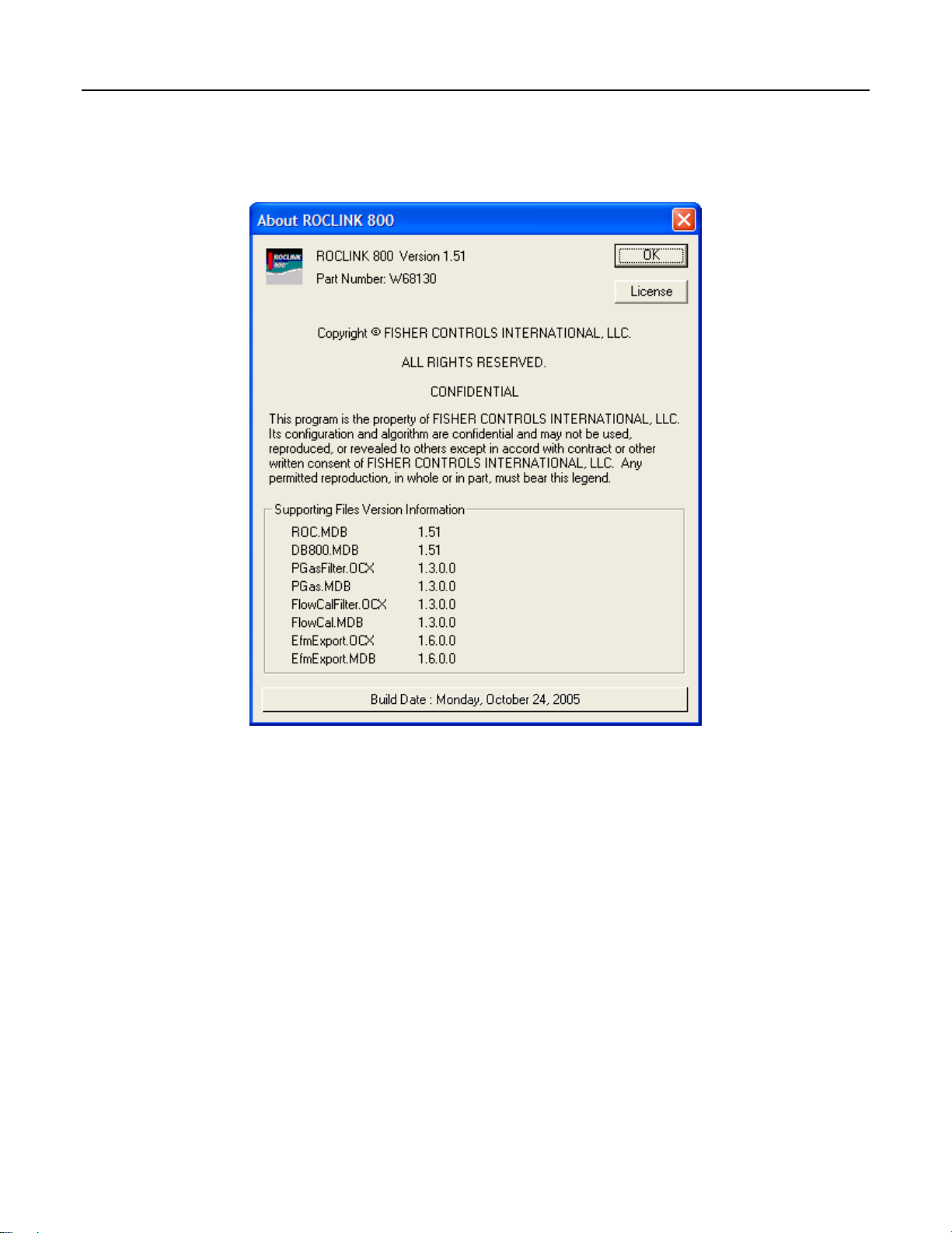
1.6.6 About ROCLINK 800
Select Help > About ROCLINK 800 to view the ROCLINK 800 version number and other information,
such as Supporting Files Version Information.
Figure 1-3. About ROCLINK 800 (ROC800-Series)
1.6.7 Basic Navigation
When you start the ROCLINK 800 software, the Device Directory displays. After you connect to a ROC
or FloBoss, the Configuration Tree View displays. Refer to Figure 1-7.
Use the + and – symbols to display or hide various options. Double-click a point to display the
associated parameter configuration screen. You can also use the menu options and buttons to display the
associated parameter configuration screen.
The Status Line at the bottom of the Device Directory and Configuration Tree View serves two
purposes. First, on the left side of the line, brief information about the device being connected. Second,
on the right side of the line, the device on-line or off-line status and system time display.
Rev. Dec-05 ROCLINK 800 Software Basics 1-12
Page 22
ROCLINK 800 User Manual
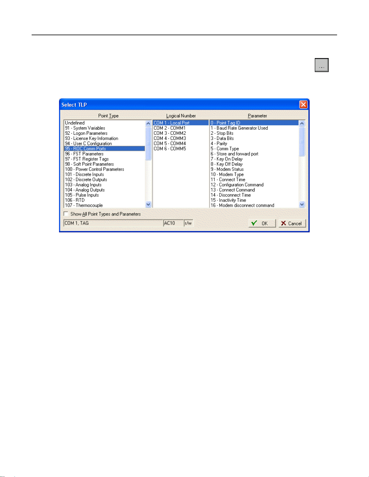
1.6.8 TLP Box Selections
Throughout ROCLINK 800 software, the Select TLP dialog can be accessed by clicking the
browse button with three dots. The Select TLP dialog allows you to assign specific inputs and
outputs to parameters. ROCLINK 800 software uses Point Type (T), Logical Number (L), and
Parameter (P) to define point locations.
Figure 1-4. Select TLP
To use the Select TLP dialog box:
1. Select the Point Type from the list. This opens a list of logical numbers and parameters that
belong to that Point Type.
2. Select the Logical Number. In the configuration screens, the Logical Number is generally
referred to as Point Number or Number.
3. Select the specific Parameter. These are usually called by the same term as the Tag on the
configuration screen. Click OK.
The display field at the bottom of the Select TLP dialog displays the numeric point location of the TLP
point or a text abbreviation, depending on the setting in the Tools > Options window.
Rev. Dec-05 ROCLINK 800 Software Basics 1-13
Page 23

ROCLINK 800 User Manual
1.6.8.1 Display TLP Options
Select Tools > Options to set whether TLPs display as text or numbers in TLP display fields throughout
ROCLINK 800 software, including the FST Editor. For example, the TLP for Register 2 of FST 1 could
display as either “FST 1,R2” or “96, 0, 3”.
Figure 1-5. TLP Options
Select Tools > Options to set the time interval, in seconds, at which the AutoScan feature on various
screens in ROCLINK 800 software will poll the ROC or FloBoss device. Click the AutoScan button to
cause ROCLINK 800 software to poll the device automatically, until the StopScan button is clicked.
1.6.9 AutoScan Update Interval Option
Select Tools > Options to set the time interval, in seconds, at which the AutoScan feature on various
screens in ROCLINK 800 software will poll the ROC or FloBoss device. Pushing the AutoScan button
on any screen will cause ROCLINK 800 software to poll the device automatically, until the StopScan
button is pushed.
1.7 Configuration Basics
Configuration of a ROC or FloBoss unit can be performed by altering an existing configuration file or
by starting a new configuration file.
The full configuration procedure involves using the menu functions or Configuration Tree Menu to
access the configuration screens. Some of the configuration screens may not be required for your
application or may not be available for your type of ROC or FloBoss.
The following checklists present the order of configuration in a typical application. Omit configuration
screens for modules and accessories that do not appear in your hardware configuration and for control
elements (PID, FST, and such) that do not apply to your application.
Rev. Dec-05 ROCLINK 800 Software Basics 1-14
Page 24

ROCLINK 800 User Manual
1.7.1 Configuration Checklist (ROC800-Series)
For a ROC800-Series unit:
♦ ROC menu > ROCLINK 800 Security (logon)
♦ Device Directory > Comm Port > Properties (PC communication configurations)
♦ ROC menu > Security (User List and Comm Port Security)
♦ ROC menu > Clock
♦ ROC menu > Information (system variables)
♦ Utilities menu > License Key Administrator (for user programs, DS800 programs and AGA
Meter Runs)
♦ Meter menu > Setup > Station (for English or Metric Unit selection)
♦ ROC menu > Comm Ports (ROC communication configurations)
♦ Configure menu > I/O menu > AI, AO, DI, DO, PI, HART, MVS, RTD, and T/C
♦ Meter menu > Station Configuration
♦ Meter menu > Orifice or Turbine Meter Setup
♦ Configure menu > History Segments and History Points (history database)
♦ Configure menu > Control menu > PID Loop
♦ Configure menu > Radio Power Control (for communications sleep mode)
♦ Utilities menu > FST Editor
♦ View menu > Display > New or from File (for custom PC displays)
♦ Utilities menu > Keypad Display (for ROC Keypad Display)
♦ ROC menu > Flags (for saving and system variables to Flash memory)
Rev. Dec-05 ROCLINK 800 Software Basics 1-15
Page 25

ROCLINK 800 User Manual
1.7.2 Configuration Checklist (ROC300-Series)
For a ROC300-Series unit:
♦ Utilities menu > ROCLINK 800 Security (logon)
♦ Device Directory > Comm Port > Properties (PC communication configurations)
♦ ROC menu > Security (User List and Comm Port Security)
♦ ROC menu > Clock
♦ ROC menu > Information (system variables)
♦ ROC menu > Comm Ports (ROC communication configurations)
♦ Configure menu > I/O menu > AI, AO, DI, DO, and PI
♦ Meter menu > Setup (Orifice or Turbine meter)
♦ Meter menu > History (Meter run history setup)
♦ Configure menu > Control menu > PID Loop
♦ Configure menu > History Points (history database)
♦ Configure menu > LCD
♦ Configure menu > Radio Power Control (communications sleep mode)
♦ Utilities menu > FST Editor
♦ ROC menu > Flags (for saving and system variables to Flash memory)
1.7.3 Configuration Checklist (FloBoss 100-Series)
For a FloBoss 100-Series unit:
♦ ROC menu > ROCLINK 800 Security (logon)
♦ Device Directory > Comm Port > Properties (PC communication configurations)
♦ ROC menu > Security (User List and Comm Port Security)
♦ ROC menu > Clock
♦ ROC menu > Information (system variables)
♦ ROC menu > Comm Ports (ROC communication configurations)
♦ Configure menu > I/O menu > AI, AO, DI, DO, and PI
♦ Meter menu > Setup (orifice or turbine meter)
♦ Meter menu > History (Meter run history setup)
♦ Configure menu > Control menu > PID Loop
♦ Configure menu > History Points (history database)
♦ Configure menu > LCD User List
♦ Configure menu > Radio Power Control (for communications sleep mode)
♦ Utilities menu > FST Editor
♦ View menu > Display > New or from File (for custom PC displays)
♦ ROC menu > Flags (for saving and system variables to Flash memory)
Rev. Dec-05 ROCLINK 800 Software Basics 1-16
Page 26

ROCLINK 800 User Manual
1.7.4 Configuration Checklist (FloBoss 407)
For a FloBoss 407 unit:
♦ Utilities menu > ROCLINK 800 Security (logon)
♦ Device Directory > Comm Port > Properties (PC communication configurations)
♦ ROC menu > Security (User List and Comm Port Security)
♦ ROC menu > Clock
♦ ROC menu > Information (system variables)
♦ ROC menu > Comm Ports (ROC communication configurations)
♦ Configure menu > I/O menu > AI, AO, DI, DO, PI, and MVS
♦ Meter menu > Setup (Orifice or Turbine meter)
♦ Meter menu > History (Meter run history setup)
♦ Configure menu > Control menu > PID Loop
♦ Configure menu > History Points (history database)
♦ Configure menu > LCD User List
♦ Configure menu > Radio Power Control (communications sleep mode)
♦ Utilities menu > FST Editor
♦ ROC menu > Flags (for saving and system variables to Flash memory)
1.7.5 Duplicating a Configuration
You can duplicate the configuration for another ROC or FloBoss unit by using these menu functions in
the following order:
1. File > Save Configuration to save the configuration to a specified file.
2. ROC > Direct Connect (Local Port) or Connect (modem) to connect physically to the second
unit, and then communicate.
3. File > Download loads the configuration into the unit.
After you have loaded configuration data into the second ROC (Step 3) and changed it as needed, you
can save the configuration to its own disk file by using Step 1.
Rev. Dec-05 ROCLINK 800 Software Basics 1-17
Page 27

ROCLINK 800 User Manual
1.8 Creating a New Configuration File
The new configuration file screen allows you to create a configuration file off-line with the basic
information about the meters and modules that will be installed on the ROC or FloBoss unit for which
the new configuration was created.
1. Select File > New.
Figure 1-6. New File Configuration Example (ROC800-Series)
2. The Type parameter indicates the type of ROC or FloBoss unit.
3. For the ROC800-Series, select the type of I/O or Comm 809 Modules that will reside in each of
the nine module slots of the ROC800-Series unit.
4. For the FloBoss 100-Series, select the type of termination board (I/O Type). Selections are 4
point (old style termination board) or 6 point (new style) with or without I/O points. When 6
point with I/O is selected, External I/O selections appear. Be sure to select the types of I/O for
which the termination board switches and wiring are configured.
5. For the ROC800-Series, enter the number of PID loops, FSTs, Stations, Sampler/Odorizers,
Orifice Meters, and Turbine Meters that will be configured. Only activate the necessary number
of devices.
6. For the FloBoss 100-Series, enter the number of PID Loops.
7. For the FloBoss 100-Series, select the maximum number of History Points in Standard and
Extended History (103 History Sizing). Be sure to select this carefully, as History Points cannot
be added later without clearing current history present in the unit. Standard history affects the
amount of available extended history.
Rev. Dec-05 ROCLINK 800 Software Basics 1-18
Page 28

ROCLINK 800 User Manual
8. Save the configuration file. ROCLINK 800 files have the extension .800.
9. Establish an on-line connection to the ROC or FloBoss unit.
10. Set the parameters and point assignments, as necessary.
The Type parameter indicates the type of ROC or FloBoss unit.
For the FloBoss 100-Series, select the type of termination board (I/O Type). Selections are 4 point (old
style termination board) or 6 point (new style) with or without I/O points. When 6 point with I/O is
selected, External I/O selections appear. Be sure to select the types of I/O for which the termination
board switches and wiring are configured.
For the ROC800-Series, enter the number of PID loops, FSTs, Stations, Sampler/Odorizers, Orifice
Meters, and Turbine Meters that will be configured. Only activate the necessary number of devices. For
the FloBoss 100-Series, enter the number of PID Loops.
For the ROC800-Series, select the type of I/O or Comm 809 Modules that will reside in each of the nine
module slots of the ROC800-Series unit.
For the FloBoss 100-Series, select the maximum number of History Points in Standard and Extended
History (103 History Sizing). Be sure to select this carefully, as History Points cannot be added later.
Optionally, the FloBoss 100-Series units have I/O. When 6 point I/O termination board is selected,
External I/O selections appear. Be sure to select the types of I/O for which the termination board
switches and wiring are configured.
1.8.1 Opening a Configuration File
The Open option allows you to open an existing configuration file either on-line (from a ROC or
FloBoss unit) or off-line (from the PC hard drive or disk). Configuration files are created using the Save
Configuration function. To open a configuration file:
1. Establish an on-line connection to the ROC or FloBoss, if opening a file on-line.
2. Select File > Open.
3. Select the configuration file name. ROCLINK 800 files have the extension .800.
4. Alter the parameters and point assignments as necessary.
Once the configuration file is opened, it automatically becomes active and you may edit the file off-line.
The configuration file may also be loaded into a ROC by using the Download function.
Rev. Dec-05 ROCLINK 800 Software Basics 1-19
Page 29

ROCLINK 800 User Manual
1.8.2 Configuration Tree Menu
When you open a configuration file or go on-line with a ROC or FloBoss unit, the Configuration Tree
appears on the screen. It has a hierarchy tree with the configurable items in the configuration, such as
I/O, Meter Runs, and History.
Figure 1-7. Configuration Tree
Rev. Dec-05 ROCLINK 800 Software Basics 1-20
Page 30

ROCLINK 800 User Manual
SECTION 2 – CONFIGURING COMMUNICATIONS AND
SECURITY
This section describes how to configure the communication ports on a PC and on a ROC or FloBoss. It
also describes how to use the Connect and Direct Connect features in ROCLINK 800 software and
security controlling access to the ROC or FloBoss and ROCLINK 800 software.
Security can be controlled in two ways:
♦ ROCLINK 800 Security – The ROCLINK 800 Security screen allows you to control who can
log on to ROCLINK 800 software and which screens they can access. Refer to Section 2.2,
ROCLINK 800 Security, on page 2-5.
♦ Device Security – Device Security screen controls who has access to the Comm Ports on the
ROC or FloBoss device. Refer to Section 2.3, Device Security, on page 2-6.
Note: Security Access Levels enable you to control which users have access to specific
ROCLINK 800 functions. Refer to Section 2.1, Security Access Levels, on page 2-2.
Before attempting to connect to a ROC or FloBoss, configure communication parameters in two places:
♦ ROCLINK 800 Communications – The Device Directory communication configurations allow
ROCLINK 800 software to communicate to an individual ROC or FloBoss unit. Refer to Section
2.6, ROCLINK 800 Communications, on page 2-17.
♦ Communication Ports on the ROC and FloBoss – Use the ROC > Comm Ports to set up
communication ports available for incoming or outgoing communications with the ROC or
FloBoss. Refer to Section 2.7, Communication Ports on the ROC and FloBoss, on page 2-21.
In this Chapter
Section Page
2.1 Security Access Levels...................................................................................................................2-2
2.2 ROCLINK 800 Security .................................................................................................................2-5
2.3 Device Security...............................................................................................................................2-6
2.4 License Key Administrator (ROC800-Series).............................................................................. 2-13
2.5 Device Directory...........................................................................................................................2-14
2.6 ROCLINK 800 Communications .................................................................................................2-17
2.7 Communication Ports on the ROC and FloBoss...........................................................................2-21
2.8 Connecting to a ROC or FloBoss..................................................................................................2-36
2.9 Troubleshooting Communications................................................................................................ 2-38
Rev. Dec-05 Configuring Communications and Security 2-1
Page 31

ROCLINK 800 User Manual
2.1 Security Access Levels
Refer to Table 2-1. The Menu Options focus on the activity while you use the Access Levels to
increase or decrease responsibility levels within the Menu Options.
Note: If security is enabled on any port, at least one user must have the highest level of security
(level 5).
Note: Login requests are rejected when ROCLINK 800 Access Levels are greater than Device
Security.
Table 2-1. Security Access Levels
Menu Menu Option Access Level
ROC Security 5
Utilities License Key Administrator 5
Utilities ROCLINK 800 Security 5
Utilities Update Firmware 4
Utilities Upgrade Hardware 4
Utilities Upgrade to FlashPAC 4
Utilities User Program Administrator 4
Configure Control > DS800 3
Configure Control > FST Registers 3
Configure Control > PID Loop 3
Configure Control > Radio Power Control 3
Configure Control > Sampler Odorizer 3
Configure History Points 3
Configure History Segments 3
Configure I/O > AI Points 3
Configure I/O > AO Points 3
Configure I/O > DI Points 3
Configure I/O > DO Points 3
Configure I/O > MVS Sensor 3
Configure I/O > PI Points 3
Configure I/O > RTD Points 3
Configure I/O > Soft Points 3
Configure I/O > System AI Points 3
Configure I/O > T/C Points 3
Configure LCD User List 3
Configure Modbus > Configuration 3
Configure Modbus > History 3
Configure Modbus > Master Modem 3
Configure Modbus > Master Table 3
Configure Modbus > Registers 3
Configure Opcode Table 3
Configure User Data 3
File Download 3
File New 3
File Save Configuration 3
ROC Clock 3
Rev. Nov-05 Configuring Communications and Security 2-2
Page 32

ROCLINK 800 User Manual
Menu Menu Option Access Level
ROC Comm Ports 3
ROC ROC Flags 3
ROC ROC Information 3
Tools Options 3
Utilities AI Calibration Values 3
Utilities Convert EFM File 3
Utilities FST Editor 3
Utilities MVS Calibration Values 3
Utilities RTD Calibration Values 3
View Display > New 3
Meter Calibration > Orifice Meter 2
Meter Calibration > Turbine Meter 2
Meter History 2
Meter Plate Change 2
Meter Setup > Orifice Meter 2
Meter Setup > Station 2
Meter Setup > Turbine Meter 2
Meter Values > Orifice Meter 2
Meter Values > Turbine Meter 2
ROC Collect Data 2
View Calibration Report 2
View EFM Report 2
File Close 1
File Open 1
File Print Configuration 1
File Recent Files 1
ROC Memory 1
View Alarms > From File 1
View Alarms > From ROC 1
View Events > From File 1
View Events > From ROC 1
View History > Between Dates 1
View History > From File 1
View History > From ROC 1
View I/O Monitor 1
Edit Copy 0
Edit Cut 0
Edit Paste 0
Edit Undo 0
File Exit 0
File Print 0
File Print Setup 0
Help About ROCLINK 0
Help Help Topics 0
ROC Connect 0
ROC Direct Connect 0
Tools Customize 0
Rev. Dec-05 Configuring Communications and Security 2-3
Page 33

ROCLINK 800 User Manual
Menu Menu Option Access Level
Utilities Communications Monitor 0
View Directory 0
View Display > Display 1 0
View Display > Display 2 0
View Display > From File 0
View Toolbar 0
Window Cascade 0
Window Currently Open Files 0
Window Tile 0
Rev. Nov-05 Configuring Communications and Security 2-4
Page 34

ROCLINK 800 User Manual
2.2 ROCLINK 800 Security
Select Utilities > ROCLINK 800 Security. The ROCLINK 800 Security screen allows you to control
who can log on to ROCLINK 800 software and which screens they can access. You may specify up to
21 different users. The Operator ID is used as the User ID when you login to ROCLINK 800. Refer to
Section 12, Keypad Display Security.
Note: After you initially access ROCLINK 800 software and establish security parameters,
delete the default Operator ID LOI and default Operator Password 1000 to prevent unauthorized
users from accessing and changing parameters.
Note: To delete an Operator ID, Password or Access Level, highlight the cell and use the
backspace key or Delete key.
Figure 2-1. ROCLINK 800 Security
1. Select Utilities > ROCLINK 800 Security.
2. Enter the three alphanumeric characters for the Operator ID, which is typically the initials of the
person who operates the device. Each Operator ID must be unique and is case-sensitive.
Note: The default Operator ID is LOI and the default Password is 1000.
3. Enter the four numeric characters between 0000 and 9999 to define the Password. More than
one user can have the same Password.
4. Enter the desired Access Level of the user. “0” is the lowest Access Level and allows access to
the fewest number of screens. “5” is the highest Access Level and permits access to all screens.
Each Access Level permits access to screens at that level and any inherited from lower access
levels. For example, the users with Access Level 3, have access to screens with levels 0, 1, 2, and
3. Refer to Table 2-1, Security Access Levels, on page 2-2.
Rev. Dec-05 Configuring Communications and Security 2-5
Page 35

ROCLINK 800 User Manual
2.3 Device Security
Select ROC > Security. Device Security screen controls who has access to the Comm Ports on the ROC
or FloBoss device. Refer to Section 12, Keypad Display Security.
2.3.1 Device Security – Users (ROC800-Series and FloBoss 100-Series)
Select ROC > Security. For the ROC800-Series and the FloBoss 100-Series, the Device Security screen
controls who has access to the Comm Ports on the ROC or FloBoss device. When Enabled, you must
login to use the communications port. Each communications port may be Enabled or Disabled
separately. For the ROC800-Series, the Keypad Display user and group security settings are also
configured on this screen.
The default Operator ID is LOI. The default Password is 1000.
1. Select ROC > Security.
2. Click an Operator ID field to add, edit, or remove a user.
Figure 2-2. Device Security – Users (ROC800-Series and FloBoss 100-Series)
3. Enter the Operator ID, Password, Confirmed Password, and user Access Level. Refer to
Table 2-1, Security Access Levels, on page 2-2.
Rev. Nov-05 Configuring Communications and Security 2-6
Page 36

4. Select the Group to which the user belongs.
ROCLINK 800 User Manual
Figure 2-3. Device Security – Users Maintenance (ROC800-Series and FloBoss 100-Series)
5. Click OK and click Apply.
Rev. Dec-05 Configuring Communications and Security 2-7
Page 37

ROCLINK 800 User Manual
2.3.2 Device Security – Users (FloBoss 407)
Select ROC > Security. The Device Security screen controls who has access to the Comm Ports and
LCD / Keypad on the FloBoss device. When Enabled, you must login to use the communications port.
Each communications port may be Enabled or Disabled separately. For the FloBoss 407, Device
Security also controls who has access to the Liquid Crystal Display (LCD) for the unit. Select an
Operator ID in the table to set each individual’s security, for up to 32 users.
Figure 2-4. Device Security – Users (FloBoss 407)
User Table – Select an Operator ID in the table to set each individual’s security. If you wish to create a
user, click on an empty cell in the table. The Device Security dialog box appears.
To delete an operator entry from the table, highlight a cell in that line. When the Device Security
dialog box appears, click the Remove button.
Operator ID – Enter the three alphanumeric characters for the Operator ID, which is typically the
initials of the person who operates the device through that communications port. Each Operator ID
must be unique. The Operator ID is case-sensitive. The default Operator ID is LOI. The default
Password is 1000.
Password – Enter the four numeric characters between 0000 and 9999 for the Password. Users can
have the same Password.
Note: Login requests are rejected when ROCLINK 800 Access Levels are greater than Device
Security. Refer to Table 2-1, Security Access Levels, on page 2-2.
Access Level – Enter the desired Access Level of the user. “0” is the lowest Access Level and allows
access to the fewest number of screens. “5” is the highest Access Level and permits access to all
screens. Each Access Level permits access to screens at that level and any inherited from lower
access levels. For example, the users with Access Level 3, have access to screens with levels 0, 1, 2,
and 3. Refer to Security Access Levels for a full list of the access levels. Refer to Table 2-1, Security
Access Levels, on page 2-2.
Note: If security is enabled on any port, at least one user must have the highest level of security
(level 5).
Rev. Nov-05 Configuring Communications and Security 2-8
Page 38

ROCLINK 800 User Manual
LCD ON – Select Enabled to turn the LCD Display Always ON and leave it active, or select Disabled to
allow the LCD Display to time out and turn itself off. If Enabled, the LCD remains on until the next
user logs on who has the LCD Disabled.
LCD Custom User List – Check a radio button to give a user access to the LCD Custom User List 1,
2, and 3 of an on-line FloBoss 407 for viewing, editing, or both. This includes the keypad functions.
Security On LOI, Security on COM1, and Security on COM2 – For each communications port, select
Disabled, User ID Enabled (to require security on a specific communications port), or User Access
Level Enabled (to require a specific level of security for this user).
2.3.3 Device Security – Users (ROC300-Series)
Select ROC > Security. The Device Security screen controls who has access to the Comm Ports and
optional Liquid Crystal Display (LCD) on the ROC device. When Enabled, you must login to use the
communications port. Each communications port may be Enabled or Disabled separately and you can
select the Access Level.
Figure 2-5. Device Security – Users (ROC300-Series)
User Table – Select an Operator ID in the table to set each individual’s security. If you wish to create a
user, click on an empty cell in the table. The Device Security dialog box appears. Refer to Device
Security.
To delete an operator entry from the table, highlight a cell in that line. When the Device Security
dialog box appears, click the Remove button.
Operator ID – Enter the three alphanumeric characters for the Operator ID, which is typically the
initials of the person who operates the device through that communications port. Each Operator ID
must be unique. The Operator ID is case-sensitive.
Rev. Dec-05 Configuring Communications and Security 2-9
Page 39

ROCLINK 800 User Manual
Password – Enter the four numeric characters between 0000 and 9999 for the Password. Users can
have the same Password.
Access Level – “0” is the lowest Access Level and allows access to the fewest number of screens. “5” is
the highest Access Level and permits access to all screens. Each Access Level permits access to
screens at that level and any inherited from lower access levels. For example, the users with Access
Level 3, have access to screens with levels 0, 1, 2, and 3. Refer to Security Access Levels.
Note: Login requests are rejected when ROCLINK 800 Access Levels are greater than Device
Security. Refer to Table 2-1, Security Access Levels, on page 2-2.
Security On LOI and Security on COM1 – For each communications port, select one of the following
options:
♦ Disabled – All login requests are accepted.
♦ User ID Enabled – Login requests are accepted if the User ID and Password are valid. Upon
successful login, full access is allowed.
♦ User Access Level Enabled – Login requests are accepted if the User ID and Password are
valid. Upon successful login, the user is restricted by access level. Refer to Security Access
Levels. Refer to Table 2-1, Security Access Levels, on page 2-2.
2.3.4 Device Security – Groups
Select ROC > Security. Click the Groups tab. For ROC800-Series units, with firmware version 1.50 or
greater, the Group tab establishes the Groups used in Keypad Display security. Enter a name for each
Group that you are establishing. If your application does not require a Keypad Display, do not create
Groups.
Figure 2-6. Device Security – Groups (ROC800-Series)
Rev. Nov-05 Configuring Communications and Security 2-10
Page 40

ROCLINK 800 User Manual
2.3.5 Device Security – Comm Ports (ROC800-Series and FloBoss 100Series)
Select ROC > Security. Click the Comm Ports tab. For each communications port, select one of the
following Security on options:
♦ Disabled – All login requests are accepted.
♦ User ID Enabled – Login requests are accepted if the Operator ID and Password are valid. Upon
successful login, full access is allowed.
♦ User Access Level Enabled – Login requests are accepted if the Operator ID and Password are
valid. Upon successful login, the user is restricted by access level. Refer to Table 2-1, Security
Access Levels, on page 2-2.
Figure 2-7. Device Security – Comm Ports (ROC800-Series and FloBoss 100-Series)
Rev. Dec-05 Configuring Communications and Security 2-11
Page 41

ROCLINK 800 User Manual
2.3.6 Device Security – Users / Group Summary (ROC800-Series)
Select ROC > Security. Click the Users / Group Summary tab. For ROC800-Series units, with
firmware version 1.50 or greater, the User/Group Summary tab displays which users belong to which
Group. Use the Users and Groups table to quickly make changes to the ROC > Security settings.
Figure 2-8. Device Security – User/Group Summary (ROC800-Series)
Rev. Nov-05 Configuring Communications and Security 2-12
Page 42

ROCLINK 800 User Manual
2.4 License Key Administrator (ROC800-Series)
Select Utilities > License Key Administrator to access the license information on any license key that
may currently be installed in the CPU of the ROC800-Series. From this screen, you can view and
manage the licenses stored on the license key(s).
AGA Meter Runs and some applications, such as DS800 and user programs, must have a license key
installed in the ROC800-Series CPU with the appropriate entry to allow execution of the application.
The Application Code is specific to the application and is defined by the application provider. The
application code should not be mistaken for license quantity. License Application Code values may not
be merged or split.
♦ In a DS800 license, the application code has no meaning and is 0.
♦ In a User Program license, the application code’s meaning is documented in the user program’s
manual.
♦ In an AGA 3/7/8 license, the application code will be 6, which indicates six Meter Runs per
license. If the quantity of licenses is 2, then 12 Meter Runs can execute.
Figure 2-9. License Key Administrator (ROC800-Series)
The License Key grids provide a list of the licenses currently on the key in the upper (#1) and lower (#2)
key slots of the CPU module. Licenses may be moved from one key to another. If both keys are full, the
Move, Merge, and Split buttons are grayed out.
Use the Move button to move licenses from one key to another key.
Use the Merge button to merge the first two similar entries by creating a single license with the
combined quantities.
Use the Split button to split a license with a quantity greater than 1. This allows multiple quantity
licenses to be split and moved between license keys. You cannot split a license with a quantity of 1.
Rev. Dec-05 Configuring Communications and Security 2-13
Page 43

ROCLINK 800 User Manual
2.5 Device Directory
The Device Directory is the first screen that displays after logging in to ROCLINK 800 software. The
Device Directory provides a way to create and maintain communications setup configurations for a PC
running ROCLINK 800 software. The communication ports on the PC can be uniquely configured to
send data to specified ROC or FloBoss units.
Figure 2-10. Device Directory
Use the + and – symbols to display or hide various options.
Note: Configuration of the PC Communication Ports to the ROC or FloBoss unit cannot be
performed within the Configuration Tree screen. You must return to the Device Directory. If you
are in a configuration, select Window > Device Directory or View > Directory to go to the
Device Directory.
The PC communication configurations allow ROCLINK 800 software to communicate to an individual
ROC or FloBoss unit. You may add, delete, or modify these communications setups and establish a tree
of Groups and Devices.
The Device Directory is used to set up the personal computer’s (PC) communications ports (COM
ports).
The ROCLINK 800 Communication Parameter Setup screen allows you to change your PC
communications port, time-out settings, and other variables, used by ROCLINK 800 software when
establishing a connection to a Device.
In order for ROCLINK 800 software to communicate with a Device, ROCLINK 800 software must
know to which device it is communicating. Each Device within a Group is given a unique Device
Address.
Rev. Nov-05 Configuring Communications and Security 2-14
Page 44

ROCLINK 800 User Manual
2.5.1 Device Root
The Device Root is the organizational level in the Device Directory. When you open ROCLINK 800
software, the default Device labels display in the Device Directory. You can modify these
communications setup configurations, or you can create new configurations.
Figure 2-11. Device Root
The default Device Root labels include:
♦ COM1 Device
♦ COM2 Device
♦ Modem Device
♦ Ethernet Device
♦ New Group1
♦ New Device1
♦ New Device2
The communication configurations allow ROCLINK 800 software to communicate to an individual
ROC or FloBoss unit. You may add, delete, or modify these communications setups and establish
Groups of devices. Creating a back-up file of the Device Root settings after you have configured the
settings is highly suggested. To do so, use Windows Explorer to find the ROC_user.mdb file, then create
a back-up copy of this file in case your settings should ever be corrupted.
Devices can be configured for on-line communications using the Local Operator Interface (LOI) port or
a communication port, such as a modem.
Each icon represents a different type of communications connection.
Rev. Dec-05 Configuring Communications and Security 2-15
Page 45

ROCLINK 800 User Manual
The devices can be logically organized to form Groups. A Group is typically several units in the same
geographical area. Each Group contains a list of all the devices contained within that Group.
Each ROC or FloBoss has a Tag and unique Device Address for differentiation. The Device Address
must be different from any other host system that may access the network. The Tag and Device Address
are set by clicking with the right mouse on the Device and selecting Properties.
2.5.1.1 Adding a Group
Devices can be organized to form Groups. Groups are typically units in the same geographical area or
units with something else in common. When you select a Group file, a list of all communication setups
in the Group appears below the Group.
To add a new Group under the Device Root directory or add a Subgroup to an existing Group:
1. Select the Device Root directory icon.
2. Right-mouse click.
3. Select Add a Group.
4. Right mouse click again and Rename the Group or use the default.
5. You may now wish to add a Device.
2.5.1.2 Deleting a Group
To delete a Group under the Device Directory:
1. Select a Group.
2. Right-mouse click.
3. Select Delete Group.
4. Click Yes in the Confirm Delete Message dialog.
2.5.1.3 Deleting a Device
To delete a Device under the Device Directory:
1. Select a Device by highlighting the Name next to its icon.
2. Right-mouse click on the Name.
3. Select Delete Device.
4. Click Yes in the Confirm Delete Message dialog.
2.5.1.4 Adding a Device
To add a new Device under the Device Directory or add to an existing group:
1. Select the Device Root directory icon.
2. Right-mouse click.
3. Select Add a Device.
4. Configure the communication parameters.
Note: You can place a Device connection under a Group by selecting the Group before
adding the Device connection.
Rev. Nov-05 Configuring Communications and Security 2-16
Page 46

ROCLINK 800 User Manual
2.5.1.5 Deleting All Devices
To delete all Device communication parameter configurations under the Device Root directory:
Note: This deletes all ROC units that you currently have configured.
1. Select the Device Root directory icon.
2. Right-mouse click.
3. Select Delete All Devices.
4. Click Yes in the Confirm Delete Message dialog box.
2.5.1.6 Renaming a Group or Device
To rename a Group or Device in the Device directory:
1. Select (highlight) the Device Name or Group label.
2. Right-mouse click on the Device Name or Group label.
3. Select Properties.
4. Enter the Tag of the Group label or Device Name.
5. Press OK or Apply.
2.6 ROCLINK 800 Communications
The Device Root is the organizational level in the Device Directory. When you open ROCLINK 800
software, the default Device labels display in the Device Directory. You can modify these
communications setup configurations, or you can create new configurations. Refer to 2.3, Device
Security, on page 2-6.
2.6.1 ROCLINK 800 Communications – General
The Device Directory is the first screen that displays after logging in to ROCLINK 800 software. Use
the ROCLINK 800 Communications General tab to configure basic communications for the PC running
ROCLINK 800 software.
1. Select the Device Root directory icon.
2. Right-mouse click on a communications icon.
3. Select Properties.
Rev. Dec-05 Configuring Communications and Security 2-17
Page 47

ROCLINK 800 User Manual
Figure 2-12. ROCLINK 800 Communications – General Example (ROC800-Series)
Tag – Enter the Station Name in the Tag field.
Connect – Press the Connect button to connect using the configured parameters for this PC
Communications Port.
Device Group – The Group in which the ROC or FloBoss is associated.
Device Address – The Address of the specific ROC or FloBoss with which you desire to communicate.
If you are connected to a multi-drop series of devices, enter the Device Address and Device Group
of the specific Device to which you will talk.
Note: If the PC that is running ROCLINK 800 software is connected directly to the LOI Local
Port on the device, ROCLINK 800 makes a request to Device Group of 240 and Device Address
of 240. The Local Port of a device always responds to a request for Address 240/Group 240, no
matter what Device Address and Device Group is configured in the device if the LOI Security is
valid.
Note: For communications to any port on the ROC or FloBoss, other than the Local Port, the
Device Address and Device Group in the ROCLINK Communications Parameters window
determines which device will be contacted. The Device Address and Group must match the
Device Address and Group in the ROC > Information screen. Changing the Device Address and
Group, on the ROCLINK 800 Communications Parameters window, will cause the PC to
communicate with a different device.
Note: When using a FloBoss 100-Series device, the default Device Group of 240 and Device
Address of 240 allows communications to any Comm Port.
Rev. Nov-05 Configuring Communications and Security 2-18
Page 48

ROCLINK 800 User Manual
Host Address – The PC has a default value of Address 3 and Group 1. If more than one computer
running ROCLINK 800 software will be communicating with a group of devices, either by radio or
by other multi-drop communications, the Host Address of each Device Directory setup must be
unique to avoid multiple responses. The Host Address must also be different from any other host
system that may access the communications link.
Host Group – The PC has a default value of “1.” When using ROC Protocol, the Group address must
match the address setup at the destination device in order for communications to properly transmit.
In the assignment of the Host Group and Host Address, the following convention should be used:
Host Group and Host Address limitations:
0 and 240= Reserved
Use – Select the connection type: Comm Port, Modem, or TCP/IP.
Note: If TCP/IP is selected, the Time Out parameter on the Advanced tab applies, but the other
parameters do not apply. Firmware updates cannot be transmitted over a TCP/IP connection.
PC Comm Port – If in the Use portion of the screen, you selected Comm Port, select the PC Comm
Port on the computer to be used by ROCLINK 800 software for this setup. The device can
communicate through any configured Comm Port of the PC. Typically, COMM1 or COMM2 is used
with the Local Port. Before selecting this parameter, check to see which Communications Ports are
assigned in the PC.
Baud Rate – The Baud Rate is set in the PC and used by ROCLINK 800 software to communicate with
the device through a serial port (COM port). For successful communications, the Baud Rate setup
in the ROC and the Baud Rate set here for the PC must match. If you are having difficulties
communicating to your device, set the Baud Rate in both the device and the computer to 19200 bps.
Note: When using a FloBoss 100-Series, you may need to set the Baud Rate to 9600 bps if you
are communicating simultaneously with external devices.
Phone Number – If in the Use portion of the screen, you selected Modem, enter the Phone Number of
the device to be dialed by ROCLINK 800 software.
Modem – Use the Modem drop-down list box to choose your modem. Only the modems set up from the
Modems dialog box in the Window’s Control Panel on your PC display. Ensure that the selected
modem is properly setup.
Override Default TAPI Init String – Enter a value to override your modem’s default Initialization
String configuration.
IP Address – If in the Use portion of the screen, you selected TCP/IP, enter the IP Address and Port
Number so the Ethernet port of a ROC800-Series controller may be accessed by ROCLINK 800
software. Enter the IP Address of the ROC to be accessed. The default IP Address for a ROC is
10.0.0.2.
Port Number – The Port Number of the ROC to be accessed. The default Port Number for a ROC is
4000. If these default values are changed in the ROC800-Series, all ROC Plus communications over
TCP/IP connections will be closed and you will have to re-establish a connection. Port Numbers
1113 and 1131 are reserved.
If Login to ROCLINK 800 Configuration software fails, then the TCP/IP connection closes.
Note: If the number of active ROC Plus Protocol using TCP/IP connections displayed on the
ROC > Information > Internet tab is 6, then you will not be able to establish a connection.
Rev. Dec-05 Configuring Communications and Security 2-19
Page 49

ROCLINK 800 User Manual
2.6.2 ROCLINK 800 Communications – Advanced
Use the ROCLINK 800 Communications Advanced tab to configure advanced communications for the
PC running ROCLINK 800 software.
1. Select the Device Root directory icon.
2. Right-mouse click on a communications icon.
3. Select Properties.
4. Click the Advanced tab.
Figure 2-13. ROCLINK 800 Communications Example – Advanced (ROC800-Series)
Number of Retries – Can be set from 0 to 25. Once connected, ROCLINK 800 will attempt to request
data. This is the number of times to try after the initial attempt to request data from the specified
device and before reporting a timeout error. Adjust the amount of time between retries using the
Time Out parameter.
The Number of Retries parameter does not apply to the dial-up modem, which only tries to establish
a connection once.
Tx Delay – Enables the RTS line for the amount of delay specified before transmitting data. Tx Delay
is typically used to allow a radio to fully stabilize before data is applied to transmit.
♦ For EIA-232 (RS-232) and Dial-up Modem communications, the Tx Delay and Key Off Delay
values should normally be set to 0 (zero) or the default of 0.05 seconds.
♦ For EIA-485 (RS-485) and Radio communications, the Tx Delay value is typically set to 0.1.
Rev. Nov-05 Configuring Communications and Security 2-20
Page 50

ROCLINK 800 User Manual
Time Out – The actual amount of time that ROCLINK 800 software waits to receive a valid message
after it sends a request to a device. Do not enter 0 (zero) in the Time Out field. For Dial-up Modem
communications, the Time Out value is typically set to 3 seconds.
Key Off Delay – Defines the amount of time to delay when done transmitting a message before turning
the RTS signal off. For EIA-232 (RS-232) and Dial-up Modem communications, the Tx Delay and
Key Off Delay values should normally be set to 0 (zero).
CRC Check – Select Enabled or Disabled in the ROCLINK CRC Check field for Cyclical Redundancy
Checking.
2.7 Communication Ports on the ROC and FloBoss
While in a configuration and on-line with a ROC or FloBoss unit, select ROC > Comm Ports to display
the Comm Port settings screen. Each communications port has a unique set of parameters on the screen.
The ROC > Comm Ports screen is used to setup the communications ports that are available for
incoming and outgoing communications with the ROC or FloBoss and not the personal computer
(PC). PC communication ports are setup using the Device Directory.
The communication ports located on the ROC or FloBoss provide a data link to ROCLINK 800
software, other ROC or FloBoss units, and host systems. Depending on the type of modules you are
using, the following types of communications are possible:
♦ EIA-232 (RS-232) serial communications.
♦ EIA-422 (RS-422) serial communications (ROC800-Series).
♦ EIA-485 (RS-485) multi-point serial communications.
♦ Dial-up modem communications.
♦ TCP/IP communications (ROC800-Series).
♦ Spread-Spectrum wireless radio (FloBoss 100-Series).
Table 2-2. Communication Ports for the ROC800-Series
Port Port Location Default Tag Function/Type
1 CPU RJ-45 (top) Local Port LOI / RS-232D
2 CPU RJ-45 (middle) COMM1 Ethernet
3 CPU 5-pin (bottom) COMM2 Serial / EIA-232 (RS-232)
4 Module Slot 1 COMM3
5 Module Slot 2 COMM4
6 Module Slot 3 COMM5
EIA-232 (RS-232), EIA-422 (RS-422), EIA-485 (RS-485),
Modem, or MVS
EIA-232 (RS-232), EIA-422 (RS-422), EIA-485 (RS-485),
Modem, or MVS
EIA-232 (RS-232), EIA-422 (RS-422), EIA-485 (RS-485),
Modem, or MVS
Rev. Dec-05 Configuring Communications and Security 2-21
Page 51

ROCLINK 800 User Manual
Table 2-3. Communication Ports for the FloBoss 407
Port Default Tag Function/Type
1 Local Port LOI / RS-232D
2 COMM1 EIA-232 (RS-232)
3 COMM2 EIA-232 (RS-232), EIA-485 (RS-485), or Modem
Note: COMM1 is built into the termination board of the FloBoss 407, and COMM2
is located on an optional communications card.
Table 2-4. Communication Ports for the FloBoss 100-Series
Port Default Tag Function/Type
1 Local Port LOI / RS-232D
2 COMM1 Serial / EIA-485 (RS-485)
3 COMM2 EIA-232 (RS-232), Modem, or Spread-Spectrum Radio
Note: COMM2 requires an optional communications card.
Table 2-5. Communication Ports for the ROC300-Series
Port Default Tag Function/Type
1 Local Port LOI / RS-232D
2 COMM1 EIA-232 (RS-232), EIA-485 (RS-485), or Modem
3 COMM2 EIA-232 (RS-232), EIA-485 (RS-485), or Modem
Note: COMM1 and COMM2 are located on an optional communications card.
The communication ports of the ROC or FloBoss provide a link to computers, such as one running
ROCLINK 800 software or a host computer. ROC800-Series units can have up to six communication
ports. FloBoss and ROC300-Series units can have up to three.
Select ROC > Comm Ports to set up communications ports available for the ROC or FloBoss.
Note: For FloBoss 100-Series, the Modem tab only appears after Comm Ports 3 has been
selected.
The SRBX or RBX (Spontaneous Report-by-Exception) alarming feature is available for serial
communication ports. It is not supported on the Ethernet port. This feature allows the device to call in to
a host computer when a configured alarm occurs. To prevent “nuisance” alarms from being reported to
the host, configure the parameters correctly. If you wish to configure dial-up SRBX, then a modem must
be present and appropriately configured.
When using SRBX Alarming, you must ensure that the alarms are enabled and configured for each point
you desire to monitor. Configure the alarm parameters so that an alarm occurs only when desired. These
parameters are configured on the Alarms tabs of the I/O configuration screens.
Once configured, the configuration of all communications ports should be saved to programmable ROM
using the Flash Memory Save Configuration function in the ROC > Flags screen.
Rev. Nov-05 Configuring Communications and Security 2-22
Page 52

ROCLINK 800 User Manual
Figure 2-14. Comm Port (ROC800-Series)
Figure 2-15. Comm Port (FloBoss 100-Series)
Rev. Dec-05 Configuring Communications and Security 2-23
Page 53

ROCLINK 800 User Manual
Figure 2-16. Comm Port (FloBoss 407 and ROC300-Series)
Rev. Nov-05 Configuring Communications and Security 2-24
Page 54

ROCLINK 800 User Manual
2.7.1 Comm Ports – General
Select ROC > Comm Ports to configure the communications ports on the ROC or FloBoss.
Figure 2-17. Comm Port Example (ROC800-Series)
Select the Communications Port that the device is using to communicate.
Enter the 10-character Tag name for identification of the communications port.
Comm Type (ROC800-Series) displays the type of communications port associated to this Comm Port
number, such as EIA-232 (RS-232).
Select the transmit and receive data Baud Rate in bits per second.
If Parity checks are to be performed by the communications controller, select the Parity radio button.
Select the number of Data Bits contained in an asynchronous byte, or character. This number is
typically 8.
Select the number of Stop Bits contained in an asynchronous byte, or character. This number is
typically 1.
Rev. Dec-05 Configuring Communications and Security 2-25
Page 55

ROCLINK 800 User Manual
Enter the Key On Delay to define the number of seconds to delay after turning the RTS signal on before
beginning transmission. For some older radios, the Key On Delay may need to be set as high as 0.2
seconds. For newer radios designed for data transmission, no more than 0.02 second should be required.
For Dial-up modems and EIA-232 (RS-232) communications, the Key On Delay should normally be set
at 0 seconds or may be changed to optimize communications.
Enter the Key Off Delay intervals defining the period to delay before turning the RTS signal off once a
valid message has been sent. The default of 0.01 seconds should be sufficient for most radios. For Dialup modems and EIA-232 (RS-232) communications, the Key Off Delay should normally be set at 0
seconds or may be changed to optimize communications.
Select the Port Owner (ROC800-Series). This refers to the communications protocol that will be in use
on this Port.
♦ ROC Plus Protocol/Modbus Slave configures the Port to automatically switch between
Modbus and ROC Plus protocol messages.
♦ ROC Plus Protocol Only configures the Port to only accept ROC Plus protocol messages
(Modbus Slave is disabled).
♦ Modbus Slave Only configures the Port to allow the ROC or FloBoss to act only as a Modbus
slave device (ROC Plus Protocol is disabled).
Note: It is recommended that the “Only” options be used if the messages received will only
be of this specific protocol. Otherwise, select ROC Plus Protocol/Modbus Slave if this
Comm Port is going to have both protocols communicate on it.
♦ Modbus Master configures the Port to allow the ROC or FloBoss to poll Modbus devices (ROC
Plus Protocol and Modbus Slave are disabled.)
♦ DS800 configures the Port to download and debug Development Suite 800 projects only. You
will not be able to connect two ROC800-Series units together with this option. It is exclusively
configured for DS800/PC communications.
Note: Modems are not supported for the DS800 communication type.
♦ LCD configures the port for communications with a ROC Keypad Display unit.
♦ I/O Module configures this Port to use the communications protocol residing in the I/O module.
♦ User Program 1 to 8 configures this Port to use the communications protocol residing in the
loaded user program. The user program number here will match the user program number in the
Configuration Tree menu and the User Program Administrator screen.
♦ Reserved indicates that this Port is reserved and cannot be used for communications.
For the ROC300-Series and FloBoss 407, enable RTS/CTS Handshaking, if applicable.
The Valid Receive Ctr (Counter) displays the number of valid messages received by the FloBoss 100-
Series, ROC300-Series, or FloBoss 407 on this communication port. This counter can be preset to a
value or cleared.
For the FloBoss 100-Series, Comm Board indicates if the communications port is available. Local Port
and COMM1 are always present. Comm Board and Board Type indicate an optional communications
board is installed.
Rev. Nov-05 Configuring Communications and Security 2-26
Page 56

ROCLINK 800 User Manual
2.7.2 Comm Ports – Modbus Host Parameters (FloBoss 407 and ROC300-
Series)
Select ROC > Comm Ports > Modbus Host Parameters tab to configure the Modbus communications on
the ROC or FloBoss.
Figure 2-18. Modbus Host Parameters (FloBoss 407 and ROC300-Series)
Note: Modbus functionality is not resident in the firmware. The Modbus User Program must be
loaded and enabled for this tab to be relevant.
1. Select ROC > Comm Ports.
2. Select the host Comm Port and click the Modbus Host Parameters tab.
3. Select the Start Transmission Active radio button to enable Modbus transmission.
4. Enable Continuous Polling to continuously poll for Modbus messages.
5. Enter the Starting Host Request line number entry in the host table where you desire the poll to
begin. The poll request continues through each line, starting at the value entered in this field,
until it reads a 0 in the Modbus host table.
6. Enter the Host Poll Delay to specify the amount of time in seconds to wait between poll
transmissions.
The Transmission Status displays the current status of the Modbus program.
Rev. Dec-05 Configuring Communications and Security 2-27
Page 57

ROCLINK 800 User Manual
2.7.3 Comm Ports – Modem
Select ROC > Comm Ports > Modem tab to configure the Modem communications ports on the ROC or
FloBoss.
Figure 2-19. Comm Port – Advanced Example (ROC800-Series)
Select Modem Type Internal when an internal modem is detected. Select None when using a Serial
link to the host or External when using a Modem that is external to the ROC or FloBoss.
Note: Internal cannot be selected by the user, it is automatically set.
Set the Connect Time parameter to determine the amount of time that the ROC or FloBoss waits after
initiating a call to receive a connect message from a device (typically the modem) before it terminates
the call. The Connect Time varies from system to system and can take up to 60 seconds to make and
complete a dial up connection. If a successful connection is made, the Disconnect Time begins.
Set the Disconnect Time parameter to determine the amount of time that the ROC or FloBoss waits for
further activity on the line before it hangs up. This timer resets after each valid receive signal.
Enter the Inactivity Time in seconds that the ROC or FloBoss will wait, without receiving a signal,
before it resets the modem. The inactivity timer looks at the valid receive counter to determine if the
signal has been received.
Enter the Config Command characters required to initialize the modem. For external modems, refer to
the manufacturer’s literature. For an internal modem, use the default value or the modem card may not
operate correctly. Refer to your modem’s documentation for default Config Command characters.
Rev. Nov-05 Configuring Communications and Security 2-28
Page 58

ROCLINK 800 User Manual
Enter the Hayes-style Connect Command required to contact the host. Typically, this is the command
ATDT followed by the telephone number. This parameter is required only for dial-out operations, such
as for SRBX Alarming.
For example, ATDT5155551212
For a ROC800-Series, enter the Hayes-style Disconnect Command required to disconnect the contact
to the host. Typically, this is the command ATH0.
The Modem Status numerically displays the result code.
Result Code Definition
0 = OK Successfully executed command line
1 = CONNECT Connection established
2 = RING Ring signal detected
3 = NO CARRIER Carrier not detected/lost (N ot supported by the FloBoss 100-Series)
4 = ERROR Error in command line (Not supported by the FloBoss 100-Series)
6 = NO DIAL TONE No dial tone detecte d (Not supported by the FloBoss 100-Series)
7 = BUSY Busy signal detected (Not supported by the FloBoss 100-Series)
8 = NO ANSWER Line not picked up on the called end (Not supported by the FloBoss 100-Series)
Rev. Dec-05 Configuring Communications and Security 2-29
Page 59

ROCLINK 800 User Manual
2.7.4 Comm Ports – SRBX or RBX
Select ROC > Comm Ports > SRBX or RBX tab to configure the Spontaneous-Report-by-Exception
alarming features on the ROC or FloBoss.
Figure 2-20. Comm Port – SRBX Example (ROC800-Series)
Enables or Disables SRBX Mode or RBX Mode for Spontaneous-Report-by-Exception alarming on this
Comm Port.
When using SRBX Alarming, you must ensure that the alarms are enabled and configured for each point
you desire to monitor. Configure the alarm parameters so that an alarm occurs only when desired. These
parameters are configured on the Alarms tabs of the I/O, MVS, and Meter Setup configuration screens.
Enter the SRBX Host Address and SRBX Host Group number of the host to which the SRBX feature
is communicating.
Defines the time in seconds between attempts to transmit an SRBX message. There is a Delay parameter
associated with each Retry Count parameter.
Rev. Nov-05 Configuring Communications and Security 2-30
Page 60

ROCLINK 800 User Manual
The SRBX Attempts #1 to #3 (Retry Count) is the number of attempts a message is repeated if a valid
response is not obtained on the first attempt. Attempts include the initial message, plus the retries. The
three Retry Count parameters each have an associated Delay parameter. This allows you to set up
different length delays for successive retries. Selecting Fixed Number allows you to enter a value for
how many times a message is retried after the first unsuccessful attempt. Note that a “0” entry causes no
retries. Selecting Continuous (255) causes continuous retries that can only be stopped when the host
acknowledges the SRBX alarm.
For example: If you set
Retry Count #1 to “2” and Delay #1 to “10”,
Retry Count #2 to “1” and Delay #2 to “20”,
then after the first unsuccessful attempt to communicate with the host, the device tries two more
times (after waiting 10 seconds each time), and once more (after waiting 20 seconds).
Defines the time in seconds between attempts to transmit an SRBX message. There is a Delay parameter
associated with each Retry Count parameter.
Enable Extra Key On Delay (FloBoss 100-Series, ROC300-Series, and FloBoss 407) to add an
additional amount of time to delay prior to transmitting an RBX message after turning the RTS signal
on. This parameter may be required for radio communications.
For the FloBoss 100-Series unit, the RBX Ack Timeout field displays the amount of time that is
allowed for the host to respond with an ACK (acknowledge) to the SRBX message from the FloBoss
100-Series unit. If the ACK fails to be received within the timeout period, the FloBoss 100-Series unit
retries the SRBX messages.
The SRBX Alarm Index indicates the ROC or FloBoss alarm currently being reported through SRBX.
The SRBX Status parameter indicates the status of RBX messaging, either Active or Inactive. Active
indicates that an SRBX alarm is being processed.
Rev. Dec-05 Configuring Communications and Security 2-31
Page 61
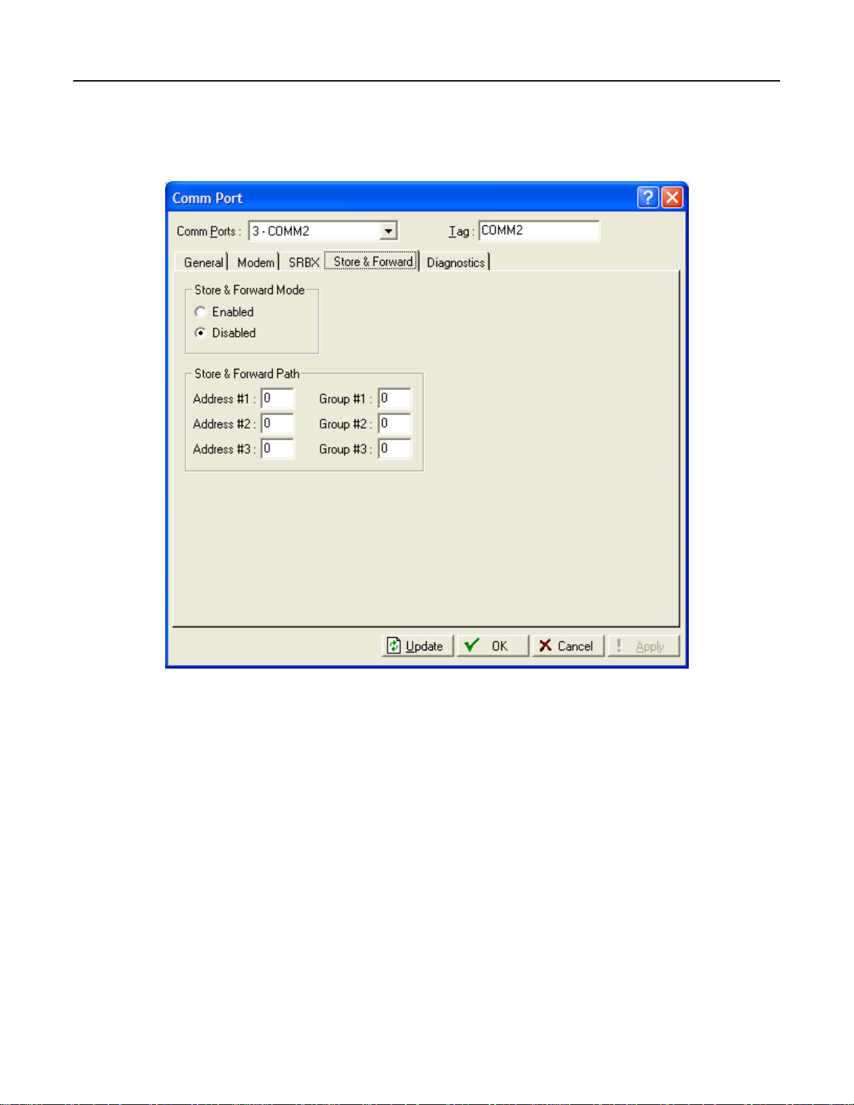
ROCLINK 800 User Manual
2.7.5 Comm Ports – Store & Forward (ROC800-Series and FloBoss 407)
Select ROC > Comm Ports > Store & Forward tab to configure the Store & Forward features on the
ROC or FloBoss.
Figure 2-21. Comm Ports – Store & Forward (ROC800-Series and FloBoss 407)
Select Store & Forward Port (FloBoss 407 and ROC300-Series) Same Port to transmit a received
message out using the same communications port, or select Opposite Port to transmit using an alternate
communications port.
Note: Only COMM1 and COMM2 Ports are supported.
Enter the Store & Forward Path Address and Group numbers of the devices that need to receive this
SRBX message and forward it on to the next device to extend the communications path. You may also
specify addresses for other devices that support the ROC Protocol. The device specified by the last nonzero Address/Group then sends the message to the host specified by the previous parameter.
If Store & Forward Mode (ROC800-Series) is Enabled, all Store and Forward messages transmit out
the Port selected in the General tab. If it is Disabled, none will be sent.
Rev. Nov-05 Configuring Communications and Security 2-32
Page 62

ROCLINK 800 User Manual
2.7.6 Comm Ports – Diagnostics (ROC800-Series)
Select ROC > Comm Ports > Diagnostics tab to view the communications diagnostic features on the
ROC.
Figure 2-22. Comm Ports – Diagnostics (ROC800-Series)
The Valid Receive Counters displays the number of valid messages received by the ROC800-Series
unit for the ROC Plus Protocol or Modbus protocol.
The Successful Message Time displays the time and date of the last valid message received for ROC
Plus protocol or Modbus protocol.
The Transmit Counter displays the number of messages sent by the ROC800-Series unit.
Invalid Message Bytes displays the number of ROC Plus or Modbus protocol bytes lost since the last
time it was cleared.
Invalid Message Byte Time displays the time and date of the last invalid message.
Rev. Dec-05 Configuring Communications and Security 2-33
Page 63

ROCLINK 800 User Manual
2.7.7 Configuring TCP/IP Communications on the Ethernet Port (ROC800-
Series)
TCP/IP connections through the ROC800-Series Ethernet port can be used for DS800, Modbus® RTU
encapsulated in TCP/IP, Modbus TCP/IP, or ROC Plus Protocol communications.
To configure TCP/IP communications:
1. Connect to the ROC.
2. If using ROC Plus, Modbus RTU Encapsulated in TCP/IP, or Modbus TCP/IP, the
parameters on the Internet tab of the ROC > Information screen must be set. Refer to Section
3.2.2.
3. If using DS800, verify the parameters and enable the DS800 communications on the Configure >
Control > DS800 screen.
4. If using Modbus RTU Encapsulated using TCP/IP or Modbus TCP/IP, select the
communications port and configure the parameters on the Configure > Modbus > Configuration
screen.
The parameters on the General, Modem, SRBX, and Store and Forward Tabs of the ROC > Comm Ports
screen do NOT apply to the Ethernet port.
The Diagnostics tab of the ROC > Comm Ports screen displays the communication statistics available
for all Modbus and ROC Plus Protocol communications transmitted using TCP/IP connections. Refer to
Parameters on Comm Ports Diagnostics Tab (ROC800-Series).
The total number of Modbus and ROC Plus Protocol over TCP/IP connections is limited to 6 of each
protocol at any given time. The number of active TCP/IP connections is displayed on the Active
Connections field on the Internet tab of the ROC > Information screen.
SRBX messaging or firmware updates cannot be transmitted over a TCP/IP connection.
Once a ROC Plus Protocol, Modbus RTU encapsulated in TCP/IP, or Modbus TCP/IP connection is
made, the communication session can be closed by a timeout. Three timeouts that can close a connection
are executed as follows:
♦ A security timeout is started after a valid Login. If a valid ROC Plus Protocol message is not
received within 60 minutes, the connection closes. The timeout is reset after each valid message.
♦ An inactivity timer for each TCP/IP connection has been added in addition to the security
timeout. The Inactivity Time field on the Internet tab of the ROC Information screen sets this
parameter in seconds. A value of 0 disables the timer. If a valid ROC Plus Protocol message is
not received within the Inactivity Time, the connection closes.
♦ Each connection will be kept alive by periodic transmissions of messages (probes). If the other
side of the connection fails to respond to 10 repetitive probes, the connection will be considered
broken and the connection closed. The amount of idle time (in seconds) before the first probe is
configurable is set in the Keep Alive Time field on the Internet tab of the ROC > Information
screen. The other 9 probes will be 64 seconds apart. The total time will be: (9*64) + the value of
the Keep Alive Time parameter.
Rev. Nov-05 Configuring Communications and Security 2-34
Page 64

ROCLINK 800 User Manual
DS800
DS800 Development Suite Software can be used to develop programs, independently of ROCLINK 800
software. These programs can be downloaded over the Ethernet port to a ROC800-Series that has the
optional license key installed.
Once DS800 is enabled on the Configure > Control > DS800 screen, the Ethernet port for DS800 is
always available to accept DS800 connections.
The ROC800-Series unit is capable of distinguishing TCP/IP messages received from DS800, in
Modbus or in ROC Protocol. The DS800 messages are routed to the correct communications task in the
ROC800-Series unit’s firmware.
ROC Plus Protocol
ROC > Security for the Ethernet port will enable or disable security for all ROC Plus Protocol based
Ethernet connections.
The Ethernet port is always available to accept ROC Plus Protocol connections.
Modbus
The ROC800-Series (firmware version 1.30 or greater) allows both Modbus RTU encapsulated in
TCP/IP and Modbus TCP/IP communications on the Ethernet port. Modbus RTU encapsulated in
TCP/IP is the form of Modbus protocol traditionally supported on serial connections in the ROC800Series, which has been or encapsulated in a TCP/IP message. Modbus TCP/IP is the protocol developed
for use over TCP/IP connections.
Note: Both Modbus RTU encapsulated in TCP/IP and Modbus TCP/IP support Slave mode only.
The Ethernet port is always available to accept Modbus connections.
The ROC800-Series is capable of supporting Modbus communications on any of the serial ports, at the
same time as Modbus RTU encapsulated over TCP/IP or Modbus TCP/IP connections.
Rev. Dec-05 Configuring Communications and Security 2-35
Page 65

ROCLINK 800 User Manual
2.8 Connecting to a ROC or FloBoss
Once ROCLINK 800 communication parameters are configured, you can connect to the ROC or
FloBoss unit. You can connect in several ways:
♦ Direct Connect – Connect to the device using the Local Operator Interface Port (LOI) if the
default communication parameters apply.
♦ Device Directory – Double-click the Device Name to connect to the device using the parameters
currently set for that port.
♦ ROC > Connect – Connect to the Device Name currently selected in the Device Root.
Note: Once you are connected (on-line), the Configuration Tree view becomes the active
screen.
2.8.1 Direct Connect
Select Direct Connect to establish a connection with a ROC or FloBoss. ROCLINK 800
software attempts to establish communications through COM1 of the PC at one of the
following baud rates: 19200, 9600, 57600, 38400, 4800, 2400, and 1200 bps. If this is
unsuccessful, the program then attempts to establish communications through the remaining
COM Ports of the PC, successively, until it receives a valid reply.
To use Direct Connect:
1. Physically connect cable to the ROC or FloBoss.
2. Launch and login to ROCLINK 800 software.
3. Do one of the following:
♦ Click on the Direct Connect icon in the Device Directory. ♦ Click the Direct Connect button on the toolbar. ♦ Select ROC > Direct Connect.
4. If this is the first time that you have connected to the ROC or FloBoss, continue to the steps for
Setting the Clock.
By default, the Local Port is the Comm Tag in the ROC > Comm Port settings screen.
For the Direct Connect option to work, security conditions must be met, and the IBM-compatible
personal computer (PC) must be connected to the Local Port (LOI) of the device with communication
settings of:
♦ 8 Data Bits
♦ 1 Stop Bit
♦ No Parity
The Direct Connect command causes ROCLINK 800 software to initiate communications with the ROC
or FloBoss device by performing a search of the PC communication ports at various baud rates. Direct
Connect then “locks on” to the first Comm Port and Baud Rate that are successful in communicating
with a device.
Rev. Nov-05 Configuring Communications and Security 2-36
Page 66
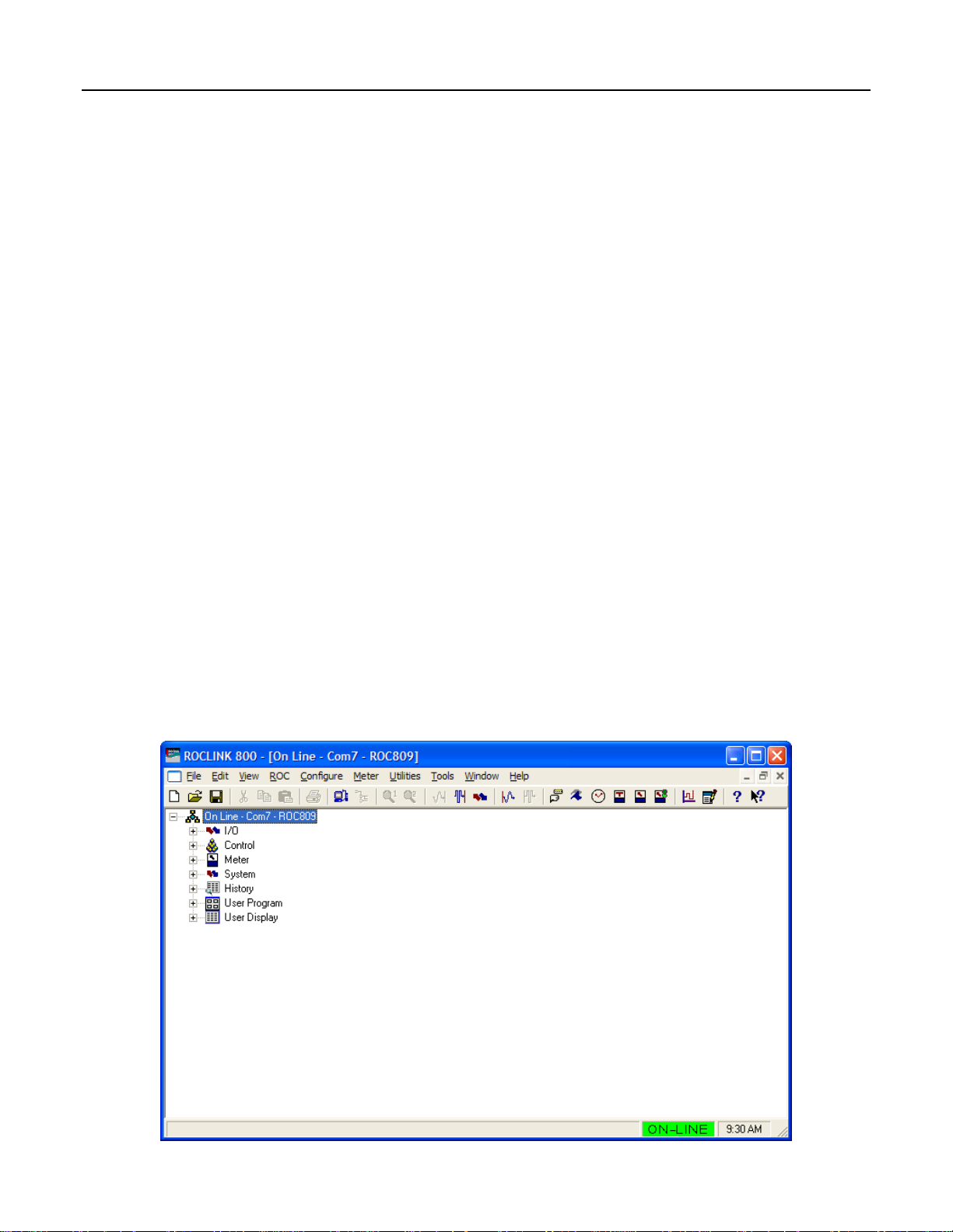
ROCLINK 800 User Manual
2.8.2 Local Operator Interface (LOI – Local Port)
The PC running ROCLINK 800 software physically connects to the ROC or FloBoss device through a
cable. For a local connection, this cable is typically a prefabricated local operator interface (LOI) cable
(available from the Flow Computer Division of Emerson Process Management). One end of the cable (a
9-pin, D-shell, female connector) plugs into a serial communications port on the PC running ROCLINK
800 software. The other end of the cable plugs into the ROC or FloBoss operator interface connector
called the Local Port.
2.8.3 Connect
To connect the computer to a remotely located ROC or FloBoss, a serial, dial-up modem, radio, satellite,
or other communications line should be installed. This connection may be made through the LOI (Local
Port) or other Communications Port on the ROC or FloBoss.
Use the Connect command to connect to a serial or dial-up modem. To use Connect:
1. Physically connect the ROC or FloBoss unit.
2. Launch and log in to ROCLINK 800 software.
3. Perform one of the following:
♦ Select a device from the Device Directory and press the <Enter> key.
♦ Double-click a device in the Device Directory.
♦ Select a device from the Device Directory and click the Connect button on the toolbar.
♦ Select ROC > Connect to connect to the device currently selected in the Device Directory.
2.8.4 Successful Login
A successful login produces an on-line connection. The Configuration Tree of the configuration that is
in the ROC or FloBoss unit displays. Refer to Configuration Tree Menu.
Figure 2-23. Successful Login Example (ROC800-Series)
Rev. Dec-05 Configuring Communications and Security 2-37
Page 67

ROCLINK 800 User Manual
The following Configuration Tree menu options are available:
I/O – Lists all available inputs and outputs by type.
Control – Displays the FST, PID, Radio Control, Sampler, and DS800 (ROC800-Series) options
enabled on the ROC > Information screen.
Station – Lists all available Stations and Meters (ROC800-Series).
Meter – Lists all available Meters (FloBoss 100-Series, FloBoss 407, and ROC300-Series).
System – Displays ROC > Information system folders, Comm Port, Flags, and Opcode Table.
History – Displays all available History Segments and points.
User Programs – Displays all installed User Programs (ROC800-Series).
User Data – Displays all installed user defined points (FloBoss 100-Series, FloBoss 407, and ROC300-
Series).
From the Configuration Tree, you may change the configuration or monitor current operations.
Once you are in the Configuration Tree menu, you can use the + and – symbols to display or hide
various options.
Double-click the desired function in the Configuration Tree to display the associated screen. Doubleclicking an icon is the same as selecting the menu bar or Toolbar button option.
If this is the first time that you have connected to the ROC or FloBoss, continue to the Setting the Clock
procedure. Refer to Setting the Clock.
2.9 Troubleshooting Communications
This section details how to troubleshoot connection and communications.
2.9.1 Troubleshooting Connection Errors
Several events can cause a connection problem:
♦ If the parameters used by ROCLINK 800 when establishing a communications link to your PC
are incorrect, a Direct Connect connection cannot be made.
♦ If ROCLINK 800 software stands idle for too long and exceeds the timeout value for a device, a
communications failure can also occur. In this case, simply log back into ROCLINK 800 and use
the Direct Connect or Connect features.
♦ If you do not have security access to the ROC or FloBoss, a connection cannot be made. A valid
User ID and Password must be configured for each user who can connect to a ROC or FloBoss in
the ROC > Security options.
♦ If the PC cannot establish a connection to the ROC800-Series by “pinging” the Device Address
(ROC Address), a TCP/IP connection through ROCLINK 800 software cannot be made.
Rev. Nov-05 Configuring Communications and Security 2-38
Page 68

ROCLINK 800 User Manual
2.9.2 Troubleshooting ROCLINK 800 Communications
Occasionally, you may need to alter your PC communications options when you are having problems
communicating with your ROC or FloBoss.
1. Select the desired Device in the Device Directory. Right-mouse click and select Properties.
2. Make sure you have specified the correct Device Address and Device Group of the ROC or
FloBoss with which you are trying to communicate. If you are communicating through the LOI
port of the device, the Device Address is 240 and Group Address is 240, which is the universal
address.
3. Click the Advanced tab. Try increasing the Time Out and/or Tx Delay.
4. Click Apply. Return to the General tab, and click Connect.
5. If you are still having trouble communicating, try increasing the Number of Retries field in the
Advanced tab screen. Click Apply. Return to the General tab, and click Connect.
6. If you are still having trouble communicating, try increasing or decreasing the Keyoff Delay
field in the Advanced tab screen. Click Apply. Return to the General tab, and click Connect.
2.9.3 Troubleshooting TCP/IP Connections
If you are unable to establish a connection between ROCLINK 800 software and the ROC800-Series
unit on the Ethernet port, verify that the PC is able to “ping” the ROC.
1. Launch the DOS command prompt and write a command to “ping” the ROC at its IP Address.
For example, C:\>ping 155.177.78.111”.
2. If the Ping Statistics Reply is similar to “Packets: Sent = 4, Received = 4, Lost = 0 <0% loss>”,
then the PC and ROC are connecting. You may need to alter the Internet communications setting
in ROCLINK 800 software. Verify all parameters on the pertinent screens. Refer to Configuring
TCP/IP Communications on the Ethernet Port (ROC800-Series).
3. If the Ping Statistics Reply is similar to “Packets: Sent = 4, Received = 0, Lost = 4 <100%
loss>”, then the PC and ROC are not connecting. You will need to review your network, your
physical connection, your router, and your PC.
Rev. Dec-05 Configuring Communications and Security 2-39
Page 69

ROCLINK 800 User Manual
2.9.4 Communications Monitor
Select Utilities > Communications Monitor and perform an operation to displays the data bytes (in
hexadecimal format) sent and received from the ROCLINK 800 software during that operation. Bytes
sent are shown in black; bytes received are shown in red. Data received since the last good response
(and before a request) are shown in aqua.
Right-click on the display to Copy highlighted data, Clear All data, or Unselect. Copied data can be
pasted in a file for analyzing.
Figure 2-24. Communications Monitor Example (ROC800-Series)
2.9.5 Disconnecting from a ROC or FloBoss
To disconnect an on-line connection, close the screen by clicking the lower of the two
Close buttons or select File > Close. This automatically closes the connection.
Figure 2-25. Device Directory
Rev. Nov-05 Configuring Communications and Security 2-40
Page 70
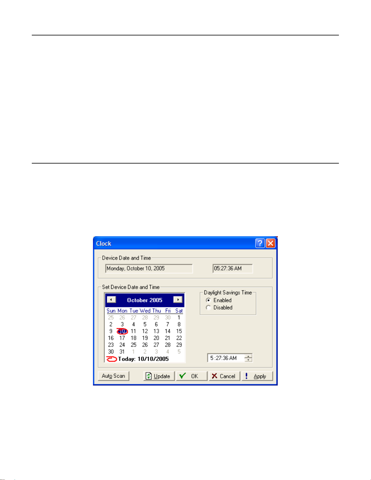
ROCLINK 800 User Manual
SECTION 3 – CONFIGURING SYSTEM PARAMETERS
This section describes how to set system preferences within the ROC or FloBoss, such as the Clock,
Security, System Information, and License Keys.
In this Chapter
Section Page
3.1 Setting the Clock .............................................................................................................................. 3-1
3.2 Configuring Device Information......................................................................................................3-2
3.3 Configuring System Flags..............................................................................................................3-15
3.1 Setting the Clock
Immediately after connecting to a ROC or FloBoss for the first time, set the Clock to ensure proper
logging of history.
The internal real-time clock provides time-stamping and control of the historical databases, Event Log,
and Alarm Log.
Note: The time stamp in the ROC or FloBoss reflects the time at the end of the period, not at the
beginning. Data collected from 0800 to 0900 is thus time-stamped 0900. This is used for the
logging of history.
Figure 3-1. Clock
1. Select ROC > Clock or click the Clock icon in the toolbar.
2. If the clock in your PC is set correctly, you can use it to set the ROC or FloBoss clock. Click
Today at the bottom of the calendar and click Apply.
Rev. Dec-05 Configuring System Parameters 3-1
Page 71

ROCLINK 800 User Manual
3. If the PC clock is not correct:
♦ Use the arrow buttons to select the correct Month and Year. You can also click the Month to
select the exact month or the Year and use the arrows to select the desired Year.
♦ Click on the desired day of the month.
♦ Click on the time field and type in the desired value (type P or A for the AM/PM field) or use
the arrows.
4. The clock can automatically compensate for daylight savings time by enabling this feature
(ROC800-Series and FloBoss 100-Series).
5. Click the Apply button.
6. Click the OK button.
3.2 Configuring Device Information
The Device Information screen establishes the Station Name, Address, Group, and other global variables
that differentiate each individual ROC or FloBoss. Other system variables set in the Device Information
screen must be established for a particular application.
Select ROC > Information. The General tab has basic information about the ROC or FloBoss. The
Points screen allows you to change the number of certain points that you want to be active. The Other
Information tab and Revision Info tab (FloBoss 100-Series) display information about the firmware and
boot firmware. The System Configuration tab (ROC800-Series) allows you to specify the four Baud
Rate Generators (BRG) possible by the ROC800-Series unit at any one given time.
The Internet tab allows you to set addresses for I/P and other Internet communication options. TCP/IP
connections can be used for either DS800, Modbus RTU encapsulated in TCP/IP, Modbus TCP/IP, or
ROC Plus Protocol communications. If the default value of the IP Address, Gateway Address, or Subnet
Mask parameter is changed, then all ROC Plus Protocol over TCP/IP connections will be closed, and
you will have to re-establish a connection.
Rev. Dec-05 Configuring System Parameters 3-2
Page 72

ROCLINK 800 User Manual
Figure 3-2. Device Information (ROC800-Series)
Figure 3-3. Device Information (FloBoss 100-Series)
Rev. Dec-05 Configuring System Parameters 3-3
Page 73

ROCLINK 800 User Manual
Figure 3-4. Device Information (FloBoss 407 and ROC300-Series)
3.2.1 Information – General
Select ROC > Information. The General tab has basic information about the ROC or FloBoss.
Figure 3-5. Device Information Example (ROC300-Series) and FloBoss 407
Rev. Dec-05 Configuring System Parameters 3-4
Page 74

ROCLINK 800 User Manual
Enter the Station Name to be logged in EFM Reports for easy site identification.
Enter a unique Address with which to differentiate each individual ROC or FloBoss device among all
units in a communications group. The Address can be assigned a value from 1 to 255. Do not assign a
value of 240 for an address.
Enter a Group to identify a set of ROC or FloBoss units for communication purposes, typically to a host
that polls the ROC or FloBoss. The Station Group can be assigned a value from 1 to 255. Do not assign
a value of 240 for a Group. All of the ROCs addressed as an area in the host have the same Station
Group.
When using the ROC Protocol, the Group and Address values must match the address setup at the
destination device in order for communications to properly transmit.
For a ROC800-Series, TCP/IP connections can be used for Modbus RTU encapsulated in TCP/IP,
Modbus TCP/IP, and ROC Plus Protocol communications. If the default value of the Address or Group
parameters is changed, then all Modbus RTU encapsulated in TCP/IP, Modbus TCP/IP, or ROC Plus
Protocol over TCP/IP connections will be closed, and you will have to re-establish a connection.
Select either US or Metric Units (FloBoss 100-Series) for calculations. If Metric units are selected, then
the AGA calculation expects all inputs to be in terms of the indicated units (such as kPa for the static
pressure input). The calculation results are then in terms of the selected units.
Enter the Contract Hour (FloBoss 100-Series, ROC300-Series, and FloBoss 407) which is the time
when values are totaled for a single day of production, accumulators are cleared, and data is logged to
the Daily History database. The Contract Hour is based on a 24-hour clock with midnight as the "0"
hour.
Select Force End of Day (FloBoss 100-Series, ROC300-Series, and FloBoss 407) checkbox, and click
Apply to cause the current day and its hourly values to be logged into memory for all historical data
except Station totals. Force End of Day also resets the daily and hourly accumulators. Force End of Day
uses one of the 35 possible slots for storing daily data.
The user may specify how many FST instructions will be executed per FST Execution period (FloBoss
100-Series). Execution period is 1 second. The default number of instructions is 20. When the default is
used, an FST with 30 sequential instructions will run in 2 execution periods; 20 in the first period and 10
in the second.
Note: Changes to this parameter will take effect in the next execution period. Re-start is not
required.
Note: To reduce the potential risk of loading on the FloBoss unit, the user should monitor the
MPU loading when changes to this parameter are made.
The Device Type field displays the type of ROC or FloBoss being configured.
Rev. Dec-05 Configuring System Parameters 3-5
Page 75

ROCLINK 800 User Manual
3.2.2 Information – Internet (ROC800-Series)
Select ROC > Information. The Internet tab (ROC800-Series) configures addresses for Internet
communications.
Figure 3-6. Information – Internet (ROC800-Series)
View the MAC Address for the ROC unit. The Media Access Control Address (MAC) Address is also
referred to as the Ethernet address and is set at the factory.
Enter the desired IP Address for the ROC. The IP Address will identify the ROC device on a TCP/IP
network.
Enter a Subnet Mask if required. The Subnet mask is a mask used to determine to which subnet an IP
address belongs.
Enter the desired Gateway Address for the ROC800-Series unit. The Gateway address identifies the
node on a network that serves as an entrance to the network on which the ROC resides.
Enter the IP Port Number for the Modbus or ROC Plus Protocol communications. The IP Port Number
determines which port that the ROC unit monitors for Modbus or ROC Plus Protocol connections when
communicating over a TCP/IP connection. The ROC Plus Protocol default is 4000. The Modbus default
is 502. Port Numbers 1113 and 1131 are reserved.
If you change the port number, the change takes effect immediately. If the default value of this
parameter is changed, then all Modbus or ROC Plus Protocol over TCP/IP connections will be closed,
and you will have to re-establish a connection.
Rev. Dec-05 Configuring System Parameters 3-6
Page 76

ROCLINK 800 User Manual
Enter the Inactivity Time in seconds. If a valid Modbus or ROC Plus Protocol message is not received
within the Inactivity Time, the connection will be closed. This timer is in addition to the security
timeout. A value of 0 will disable the timer.
Each connection will be kept alive by periodic transmissions of messages (probes). Enter the amount of
idle time before the first probe is configurable, in seconds, in the Keep Alive Time field. If the other
side of the connection fails to respond to ten repetitive probes, the connection will be considered broken
and the connection closed. The other nine probes will be 64 seconds apart. The total time will be (9 x
64) + the value of the Keep Alive Time parameter.
The total number of Modbus or ROC Plus Protocol over TCP/IP connections will be limited to six of
each type. The Active Connections field displays the number of active Modbus or ROC Plus Protocol
over TCP/IP connections.
Use the Reset All Connections button to close all active Modbus or ROC Plus Protocol over TCP/IP
connections. This button returns to an un-pressed state when connections are successfully closed.
For Modbus RTU encapsulated in TCP/IP or Modbus TCP/IP connections, select Device Address,
Slave Address, or Either Device or Slave Address. The ROC800-Series unit will respond to the
Device Address (ROC Address) configured on the General tab of the Device Information screen, to a
Slave Address configured in the Slave Address field, or to either address.
3.2.3 Information – Points
Select ROC > Information. The Points tab displays the Maximum number points are available and how
many are currently Active in the ROC or FloBoss units, such as Events, Alarms, PIDs, Stations,
Samplers, FSTs, and Meter Runs (Orifice and Turbine).
The Maximum column displays the number of Points available for the option and the Active column
displays the number of Points that are active. To conserve processor executions, set the Active fields to
the minimum value required by your application.
For FloBoss 407 units, the Points tab displays the number of database History Points contained in the
RAM areas. Base RAM is always 30; RAM1 is always 20; RAM2 is always 0. These fields are ReadOnly and cannot be changed. You can also configure the number of PIDs and AGAs.
For ROC300-Series units, the Points tab displays the number of database points contained in the RAM
areas. Base RAM is always 30; RAM1 is always 30; RAM2 is always 27. These fields are Read-Only
and cannot be changed. You can also configure the number of PIDs and AGAs.
For a FloBoss 100-Series, the Points tab also displays the number of points allocated for Standard
History and Extended History on the Configure > History Points screen. You can also configure the
number of PIDs and AGAs.
Rev. Dec-05 Configuring System Parameters 3-7
Page 77

ROCLINK 800 User Manual
Figure 3-7. Information – Points (ROC800-Series)
Figure 3-8. Information – Points (FloBoss 407 and ROC300-Series)
Rev. Dec-05 Configuring System Parameters 3-8
Page 78

ROCLINK 800 User Manual
Figure 3-9. Information – Points (FloBoss 100-Series)
Rev. Dec-05 Configuring System Parameters 3-9
Page 79

ROCLINK 800 User Manual
3.2.4 Information – Other Information
Select ROC > Information. The Other Information tab displays information about the firmware, boot
firmware, processor, and LCD (if pertinent to the type of ROC or FloBoss). The fields are read-only.
Figure 3-10. Information – Other Information Example (ROC800-Series)
Rev. Dec-05 Configuring System Parameters 3-10
Page 80

ROCLINK 800 User Manual
Figure 3-11. Other Information (FloBoss 407 and FloBoss 100-Series)
Figure 3-12. Other Information (ROC300-Series)
The Version Name, Part Number, ID, and Time Created of the firmware display.
The information about the ROM (Customer Name and Serial Number) display.
The processes in the processor (MPU Loading) display.
The amount of RAM installed in the ROC or FloBoss display.
Rev. Dec-05 Configuring System Parameters 3-11
Page 81

ROCLINK 800 User Manual
In a ROC800-Series field display when power was added or removed: Last Power Up Time (connected
to power) and Last Power Down Time (power was disconnected).
For the ROC300-Series, the LCD Installed field indicates whether an LCD is connected to the unit.
3.2.5 Information – System Configuration (ROC800-Series)
Select ROC > Information. The System Configuration tab allows you to specify the four Baud Rates
(bps) possible by the ROC unit at any given time. You may use any one of the four baud rates specified
on the System Configuration tab. A Read Only display on the Comm Ports General screen indicates
which of the four Baud Rate Generators is in use.
Figure 3-13. Information – System Configuration (ROC800-Series)
Rev. Dec-05 Configuring System Parameters 3-12
Page 82

ROCLINK 800 User Manual
3.2.6 Information – Revision Info (FloBoss 100-Series)
Select ROC > Information. The Revision Info tab displays information about the Application
Firmware or Accessory software installed in the FloBoss 100-Series unit. For example, the Accessory
field may say I/O Card, 6 Points, or Turbine Interface. When the Accessory field displays Not Used,
there are no additional accessories installed. The Part Number and Version control number also display.
Figure 3-14. Information – Revision Info (FloBoss 100-Series)
Rev. Dec-05 Configuring System Parameters 3-13
Page 83

ROCLINK 800 User Manual
3.2.7 Information – Keypad Display (ROC800-Series)
Select ROC > Information. The Keypad Display allows you to configure settings for the ROC800Series optional Display Keypad.
Figure 3-15. Information – Keypad Display (ROC800-Series)
LCD Master Switch resets the Keypad/Display task without cycling power or having to perform a
Warm-Start.
LCD Status indicates the status of the Keypad Display. OK displays if a Keypad Display unit is
installed and has a valid configuration file. An error displays if the configuration file is invalid, no
Keypad Display is installed, or if there is a CRC error.
Select the default LCD Video Mode for the display (dark text on light background) or invert the LCD
display (light text on dark background). Click Apply to change the display mode.
When LCD Backlight Power Saving Mode (ROC800-Series) is enabled, the LCD automatically shuts
off after the amount of time set in the Inactivity Time field.
LCD Firmware Version displays the firmware version currently loaded.
Rev. Dec-05 Configuring System Parameters 3-14
Page 84

ROCLINK 800 User Manual
3.3 Configuring System Flags
Select ROC > Flags to perform actions that affect the overall operation of the ROC or FloBoss device.
From this screen, a configuration can be saved to Flash memory and the ROC or FloBoss can be reinitialized if necessary. Refer to Table 3-1.
Figure 3-16. Flags (ROC800-Series)
Rev. Dec-05 Configuring System Parameters 3-15
Page 85

ROCLINK 800 User Manual
Figure 3-17. Flags (FloBoss 100-Series, FloBoss 407, and ROC300-Series)
Note: Be very careful when using the System Flags. Certain Flags cause data to be lost,
parameter values to be changed, and configuration memory to be cleared. Be sure you
understand the function of the Flags before changing them.
Note: A Reset using the Reset switch or a jumper reloads all configuration data from Electrically
Erasable Program Read-Only Memory (EEPROM) or Flash memory, clears all history, clears the
Event Log, clears the Alarm Log, and clears all ROC Displays, disables all user program tasks,
and disables all user data types.
The Reset switch or a jumper permits a restart from the boot block of the flash memory (Cold
Start) rather than from RAM (Warm Start).
The Reset switch or a jumper permits a restart from the boot block of the flash memory (Cold
Start) rather than from RAM (Warm Start).
For a FloBoss 100-Series, a Jumper Reset configures all Comm Ports back to their factory
defaults, shuts off all User Programs and FSTs. All other data remains intact.
Note: Cold Start reloads all restart configuration data and may also clear logs, displays, and
FSTs. In addition, it may cause output changes, load new accumulator values, and disable User
Program tasks and User Data Types. Generally, a Cold Start should not be used on a ROC or
FloBoss that is actively gathering data or performing control. Save or document all required
data and parameter values that could be affected before performing the Cold Start.
Rev. Dec-05 Configuring System Parameters 3-16
Page 86

ROCLINK 800 User Manual
Table 3-1. ROC > Flag Definitions
Button Device Action
Clear – Flash Memory All Clears all Flash memory.
Clear History
Configuration and Data
Cold Start All
Cold Start & Clear
Alarms
Cold Start & Clear
Alarms/Events
Cold Start & Clear All All
Cold Start & Clear
Displays
Cold Start & Clear
Events
Cold Start & Clear FSTs All
Cold Start & Clear
History
Cold Start & Clear
History Data
From Factory Defaults –
Restore Configuration
History Configuration &
Data – Clear
Save Configuration –
Flash Memory
Warm Start All
ROC800-Series
ROC800-Series
FloBoss 100-Series,
ROC300-Series,
and FloBoss 407
FloBoss 100-Series,
ROC300-Series,
and FloBoss 407
ROC800-Series
FloBoss 100-Series,
ROC300-Series,
and FloBoss 407
ROC800-Series
ROC800-Series Restores a configuration from default factory values.
ROC800-Series Clears all historical configurations and historical data.
All Saves the current configuration to Flash Memory.
Clears all Historical Database files and clears the Historical
Database configuration.
Restores a configuration from default values stored in Flash
memory. If the configuration memory is not valid, the factory
default settings are used.
Restores a configuration from default values stored in Flash
memory and clears the Alarm Log.
Restores a configuration from default values stored in Flash
memory and clears the Alarm Log and Event Log.
Restores a configuration from default values stored in Flash
memory and clears all History database files, Custom
Displays, Alarm Log, Event Log, and FSTs.
Restores a configuration from default values stored in Flash
memory and clears the ROC Custom Displays.
Restores a configuration from default values stored in Flash
memory and clears the Event Log.
Restores a configuration from default values stored in Flash
memory and clears the FSTs.
Restores a configuration from default values stored in Flash
memory and clears the History.
Restores a configuration from default values stored in Flash
memory and clears the History.
ROC or FloBoss is initialized from SRAM memory. If the
configuration is valid, databases and FSTs remain intact. If
the memory is not valid, the configuration last saved to
Flash is used. User Programs remain on.
Rev. Dec-05 Configuring System Parameters 3-17
Page 87

ROCLINK 800 User Manual
3.3.1 Returning the Device to Factory Default Settings
Sometimes it is necessary to return the ROC or FloBoss device to the original factory default settings.
The following procedure clears all saved restart configuration data contained in Flash memory. Only
factory defaults are retained.
ROC800-Series
To return the device to the original factory default settings using a ROC800-Series unit:
1. Select ROC > Flags.
2. Click Flash Memory Clear.
3. Click Yes and OK.
4. Click Restore Configuration From Factory Defaults button.
5. Click Yes and OK.
Note: You may need to re-connect as the factory default settings may be altered from the
stored data.
FloBoss 100-Series, ROC300-Series, or FloBoss 407
To return the device to the original factory default settings using a FloBoss 100-Series, ROC300-Series,
or FloBoss 407 unit:
1. Select ROC > Flags.
2. Click Flash Memory Clear.
3. Click Yes and OK.
4. Perform a Cold Start using the Cold Start & Clear ALL button.
5. Click Yes and OK.
Note: You may need to re-connect as the factory default settings may be altered from the
stored data.
Rev. Dec-05 Configuring System Parameters 3-18
Page 88

3.3.2 Flags – Advanced
Select ROC > Flags. Click the Advanced tab.
ROCLINK 800 User Manual
Figure 3-18. Flags – Advanced (ROC800-Series)
Figure 3-19. Flags – Advanced (FloBoss 407 and ROC300-Series)
Rev. Dec-05 Configuring System Parameters 3-19
Page 89

ROCLINK 800 User Manual
Figure 3-20. Flags – Advanced (FloBoss 100-Series)
Select CRC Check Enabled to perform CRC (Cyclical Redundancy Check) checking on ROC Protocol
and ROC Plus Protocol communications.
Select I/O Scanning Enabled so I/O is in normal scan mode. When Disabled, all I/O scanning is stopped
and the last values are used until scanning is resumed. This includes MVS sensors.
You can Enable and Disable I/O Scanning on the I/O point displays.
LEDs (ROC800-Series), with the exception of the LED on the Power module, can be enabled or
disabled as a power saving feature. This parameter determines how long the LEDs remain on after the
LED button on the CPU module is pressed.
For instance, with the default setting of 5 minutes, all LEDs will go off. If you press the LED button, the
LEDs become active again for 5 minutes. By placing a 0 (zero) in this field, the LEDs always stay
active.
For a FloBoss 100-Series, Power Saving Mode when enabled allows the FloBoss unit to enter sleep
mode when no activity is occurring. When disabled, the FloBoss unit will stay awake (not enter sleep
mode during no activity periods). Enabled is the default.
For a FloBoss 100-Series, select a Pass Through Mode communications option to send Pass Through
messages. By using any of the FloBoss 100-Series communications ports, Pass Through Mode allows
data to be received by one unit and then passed through to other devices connected on any other
communications port. For example, the host communicates via a radio on the FloBoss 100-Series COM2
port. Other FloBoss 100-Series units can then be connected via EIA-485 (RS-485) on the COM1 port of
the first FloBoss 100-Series unit, and then all the FloBoss 100-Series units can use the one radio to
communicate to the host.
Rev. Dec-05 Configuring System Parameters 3-20
Page 90

ROCLINK 800 User Manual
Note: If COM2 is a Dial-up modem, this port must be used as the receiving port for Pass
Through messages. It will not transmit to other field devices other than the host.
Note: The Group number of the FloBoss 100-Series receiving the data must match the Group
number of the FloBoss 100-Series unit(s) to which the data will be passed. If the Group number
does not match, the data will not be forwarded. Refer to ROC > Information to view or change
the Group number.
Select the respective port (Local Port, COM1, or COM2) for the Set RTS to High for 30 Sec option
(FloBoss 100-Series, ROC300-Series, and FloBoss 407) and click Apply to activate the RTS (Requestto-Send) signal. The RTS signal turns on for 30 seconds.
For a FloBoss 100-Series, COM1 is not available and COM2 requires an optional EIA-232 (RS-232)
communications card.
The Read I/O Flag forces the unit to search for all installed I/O modules. Select the Flag and click
Apply when an I/O module is added or removed under power.
For a FloBoss 407, the Transmitter (+T) Flag changes transmitter power to Analog Inputs when
enabled.
For the Revision M of the Termination Board with the 12V/24V jumper (P15) set to 24V, selecting
this Flag maintains the Transmitter Power at 24 volts nominal. De-select the checkbox, to change the
Transmitter Power to 12 volts nominal. If the jumper is set to 12V, this Flag essentially has no
effect.
Revisions A and B of the Termination Board, certain I/O modules (specifically the AI Loop and AO
Source) route input power back to +T. With +T flag disabled, the +T voltage returns to zero when
those modules are removed.
Revisions A and B of the Termination Board did not have a 12/24 jumper, so this feature allows the
Transmitter Voltage to be selected.
Revisions A and B of the Termination Board did not have a 12/24 jumper, so this feature allows the
Transmitter Voltage to be selected.
Select the A4/A5 Function (ROC300-Series) to determine whether the two built-in DI/PI channels in
the ROC300-Series are configured.
Rev. Dec-05 Configuring System Parameters 3-21
Page 91
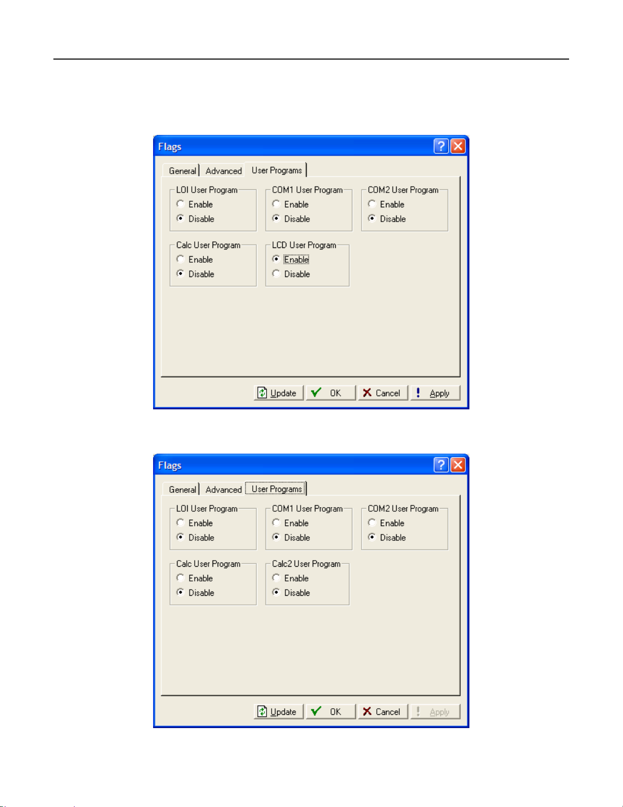
ROCLINK 800 User Manual
3.3.3 Flags – User Programs (FloBoss 100-Series, ROC300-Series, and
FloBoss 407)
Select ROC > Flags. Click the User Programs tab.
Figure 3-21. Flags – User Programs (FloBoss 407 and ROC300-Series)
Figure 3-22. Flags – User Programs (FloBoss 100-Series)
Rev. Dec-05 Configuring System Parameters 3-22
Page 92

ROCLINK 800 User Manual
LOI User Program (FloBoss 407, FloBoss 100-Series, and ROC300-Series) – If installed, allows a
User Program for the operator interface Local Port to be run. Select Disable and then click Apply to
stop the function.
COM1 User Program (FloBoss 407 and ROC300-Series) – If a user program is installed for the COM1
task, this Flag allows the User Program associated with the COM1 or COMM port on the ROC to be
run.
COM2 User Program (FloBoss 407 and ROC300-Series) – If a user program is installed for the COM2
task, this Flag allows the User Program associated with the COM2 port on the ROC to be run.
Calc User Program (FloBoss 407 and ROC300-Series) – If installed, allows the calculation user
program to be run.
Calc2 User Program (FloBoss 100-Series) – If installed, allows the second calculation User Program to
be run.
LCD User Program – If installed, allows a User Program for the optional Local Display Panel to be
run.
Rev. Dec-05 Configuring System Parameters 3-23
Page 93

ROCLINK 800 User Manual
SECTION 4 – CONFIGURING INPUTS AND OUTPUTS (I/O)
The I/O points in the ROC or FloBoss have many items that can be configured. For more information on
the types of I/O available and their functions, refer to the appropriate hardware manual.
In this Chapter
Section Page
4.1 I/O Configuration Overview........................................................................................................... 4-1
4.2 AI – Analog Input Configuration.................................................................................................... 4-2
4.3 AO – Analog Output Configuration ...............................................................................................4-9
4.4 DI – Discrete Input Configuration................................................................................................4-14
4.5 DO – Discrete Output Configuration............................................................................................4-21
4.6 PI – Pulse Input Configuration .....................................................................................................4-29
4.7 Pulse Interface Module Diagnostic (FloBoss 104).......................................................................4-37
4.8 RTD – RTD Input Configuration (ROC800-Series)..................................................................... 4-38
4.9 TC – Thermocouple Input Configuration (ROC800-Series)........................................................ 4-42
4.10 System AI – System Analog Input Configuration (ROC800-Series)........................................... 4-46
4.11 HART Input Configuration (ROC800-Series).............................................................................. 4-50
4.12 MVS Sensor (ROC800-Series or FloBoss 407)............................................................................ 4-57
4.1 I/O Configuration Overview
Configuring a ROC or FloBoss is a matter of establishing points and then configuring various
parameters.
Each Input and Output has a unique Point Number to identify the input or output. The Point Number
indicates the location of the point at the slot number of the I/O module and channel number in the
ROC800-Series. For example, DI 2-1 indicates the Point Number for a Discrete Input at module slot
number two, first channel.
The Point Number in the FloBoss 100-Series, ROC300-Series, or FloBoss 407 indicates the location of
the point on the termination board. The Point Number is automatically assigned by the device and
cannot be edited.
Note: When configuring similar point types, use the Copy (F4) and Paste (F5) options to speed
configuration of similar I/O types. For example, if you have nearly identical Analog Inputs to
configure, copy the configuration of one AI and paste that configuration into a new AI
configuration. Make the changes that are required to differentiate the two AI configurations.
Note: Each point must be individually configured. If there is more than one point of this type
available in the device, you can “page” to the other points by using Page Up and Page Down.
Points are in the same order as the I/O modules installed in the slots.
Note: For FloBoss 100-Series units with six points of I/O, select Configure > I/O > Setup to
select which types of I/O each channel will be assigned before configuring the I/O points. This
applies to the software-selectable AI/DI, AO/DO, and PI/DI channels.
Rev. Dec-05 Configuring Inputs and Outputs (I/O) 4-1
Page 94

ROCLINK 800 User Manual
4.2 AI – Analog Input Configuration
Analog Inputs are analog signals generated by measurement devices, such as pressure and temperature
transmitters, including RTD probes and pressure sensors.
Note: Use the AI configuration screens to configure a DVS for the FloBoss 100-Series and RTD
inputs for the FloBoss 100-Series and FloBoss 407.
Note: For the FloBoss 407, do not configure the second AI point if the jumper is selected to PI.
Refer to the FloBoss 407 Flow Manager Instruction Manual (Form A6013).
Select Configure > I/O > AI Points. Examine the default settings and adjust the parameters to suit your
application on each of the tabs in the order given below.
1. The General tab sets the basic parameters for the Analog Input point.
2. The Advanced tab enables you to configure features, such as filtering, A/D conversions, and
clipping for the selected Analog Input.
3. The AI Calibration tab is available to allow for calibration of the AI point while on-line. Refer to
Section 10, Calibration.
4. The Alarms tab sets the alarm parameters for this AI point.
5. After configuring all point parameters, click Apply. Use Flash Memory Save Configuration in
the ROC > Flags screen to save I/O configuration to permanent memory in case you perform a
Cold Start.
4.2.1 AI – General
Select Configure > I/O > AI Points. The General tab sets the basic parameters for the Analog Input point.
Figure 4-1. AI – General (ROC800-Series)
Rev. Dec-05 Configuring Inputs and Outputs (I/O) 4-2
Page 95

ROCLINK 800 User Manual
Figure 4-2. AI – General (FloBoss 100-Series, FloBoss 407, and ROC300-Series)
Select the Analog Input to be configured. The inputs are listed by both Point Number and Tag.
Each Point is given a Tag, which includes up to 10 characters to identify the Point being defined in the
I/O screen. Any alphanumeric characters, including spaces, may be used.
The Point Number identifies the physical location of the input. For the ROC800-Series, the Point
Number identifies the module slot – channel number.
If Scanning is set to Disabled, enter a Value to override the input. When Scanning is set to Enable,
Value displays the last Analog Input scan in engineering units.
A Units is a user-defined 10-character description for the engineering units assigned to the I/O point.
For example: PSIG, MCF, degrees F, milliamps, or volts.
Select a Scanning option. For the input to automatically process the field input, select Enabled
(Automatic Mode). When Scanning is set to Enabled, the engineering unit (EU) Value displays the last
Analog Input scan. When Scanning is set to Disabled (Manual Mode), the engineering unit (EU) Value
is no longer updated by the ROC or FloBoss. If Alarming is Enabled, a Manual Mode alarm generates
when Scanning is set to Disabled. If Scanning is set to Disabled, enter an override input in the Value
field.
Scan Period is the amount of time between updates of the Filter value. All Analog Inputs are updated
based on their individual Scan Periods. The default value is 1 second. The minimum Scan Period
allowed is 50 mSec. For a FloBoss 100-Series, the minimum Scan Period is 1 second.
Low Reading EU (engineering unit) corresponds to zero percent input. For example, if a temperature
transmitter is connected to the Analog Input with a range of –40 to 160 degrees F, the Low Reading EU
would be set to –40.
High Reading EU (engineering unit) corresponds to 100 percent input. For example, if a temperature
transmitter is connected to the Analog Input with a range of –40 to 160 degrees F, the High Reading EU
would be set to 160.
Rev. Dec-05 Configuring Inputs and Outputs (I/O) 4-3
Page 96
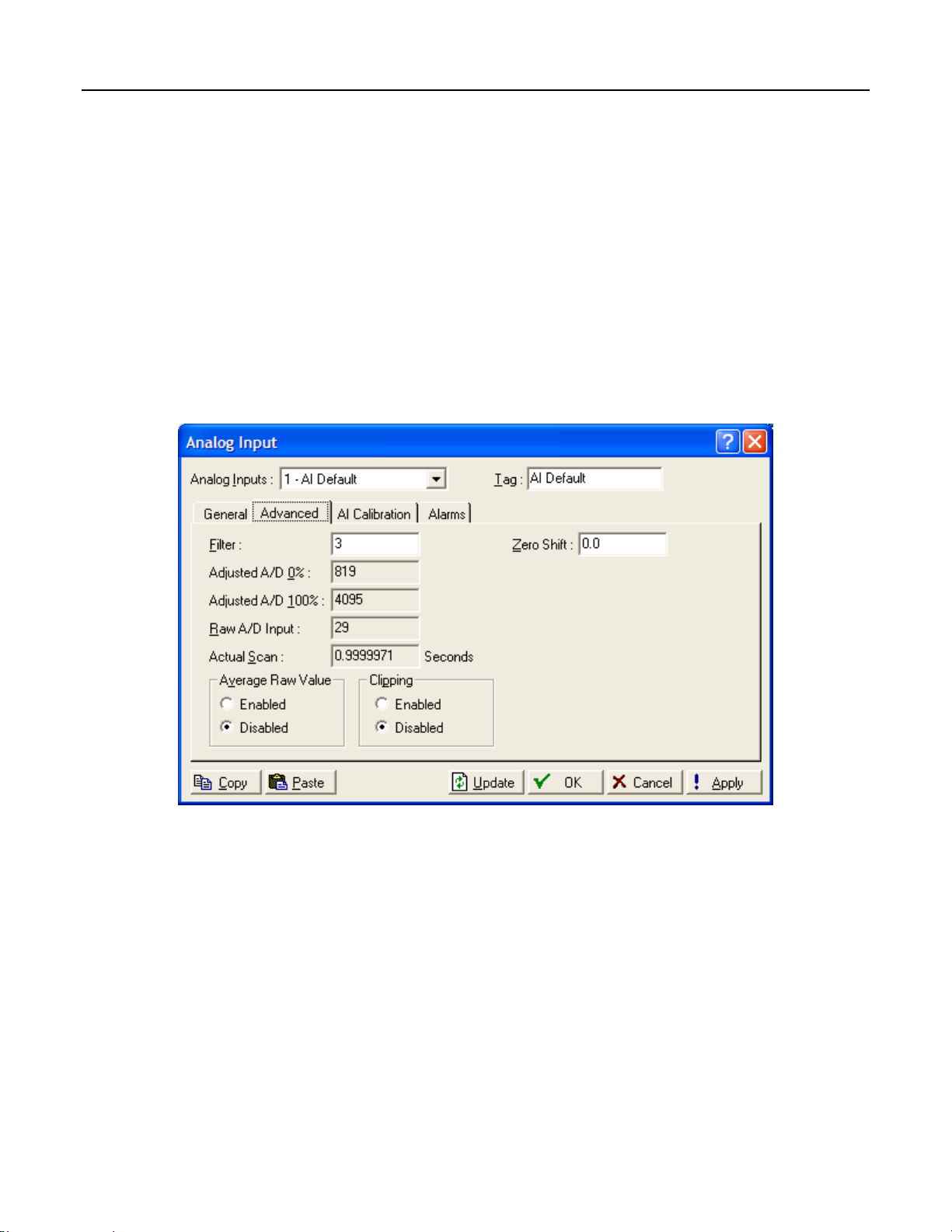
ROCLINK 800 User Manual
If you Enable Alarming, the limit alarms thresholds (four levels, Rate, and Deadband) are configured on
the Alarms tab. If you Disable Alarming, no limit alarms generate for this point. The Point Fail alarm
may appear in the Active Alarms field, but will not be logged in the Alarms file. Alarm Enable actives
the limit alarms for the point. If Alarming is set to Enabled, an alarm is generated when Scanning is
Disabled.
The Active Alarms field indicates any alarms that are active for this point. When Alarming is set to
Enabled, the limit alarms (such as Low Alarm and Rate Alarm) that are active appear. Even if Alarming
is Disabled, the Point Fail (hardware reports a malfunction) alarm and Manual (Scanning Disabled)
indicators can still appear.
4.2.2 AI – Advanced
Select Configure > I/O > AI Points. The Advanced tab enables you to configure features, such as
filtering, A/D conversions, and clipping for the selected Analog Input.
Figure 4-3. AI – Advanced (ROC800-Series)
Rev. Dec-05 Configuring Inputs and Outputs (I/O) 4-4
Page 97

ROCLINK 800 User Manual
Figure 4-4. AI – Advanced (ROC300-Series)
Figure 4-5. AI – Advanced (FloBoss 407)
Rev. Dec-05 Configuring Inputs and Outputs (I/O) 4-5
Page 98

ROCLINK 800 User Manual
Figure 4-6. AI – Advanced (FloBoss 100-Series)
Filter value is a weighted sample using a percentage of the last value plus a percentage of the new
value. The entered data is the percentage of the last value used. The Filter is calculated every Scan
Period by the formula:
ROC800-Series and FloBoss 100-Series
(Last Value × Entered %) + [New Value × (100 – Entered %)] = Filtered Value
ROC300-Series and FloBoss 407
(Last Value × [75 +(Entered % ÷ 4)]) + (New Value × [25 – (Entered % ÷ 4)]) = Filtered Value
The Adjusted A/D 0% is the calibrated Analog-to-Digital count corresponding to zero percent input. In
the Calibrate function, this value is altered to set the zero percent input exactly at the Low Reading EU
value.
The Adjusted A/D 100% is the calibrated Analog-to-Digital count corresponding to 100 percent input.
This value is used to convert the input to engineering units. In the Calibrate function, this value is altered
to set the 100 percent input exactly at the High Reading EU value.
Raw A/D Input displays the current digital count directly from the Analog-to-Digital converter.
Actual Scan displays the actual amount of time in seconds that passes between scans. This number
should be the same as shown for the Scan Period parameter on the General tab if the system is not
overloaded.
When Hold Last Value is selected, the last input value is retained on point fail. If Set to Fault Value is
selected, then the value entered as the Fault Value is written to the Filtered Value on point fail.
Enable Average Raw Values to average and calculate the raw readings during the Scan Period and use
the outcome as the Raw A/D Input during calculations. Disable this function to acquire Instantaneous
Values.
Rev. Dec-05 Configuring Inputs and Outputs (I/O) 4-6
Page 99

ROCLINK 800 User Manual
For example, when using a ROC300-Series or FloBoss 407 and Average Raw Values is enabled, an
Analog Input point configured with a Scan Period of 1.0 seconds obtains a new value from the A/D
every 50 milliseconds. During the Scan Period, 20 values are obtained from the A/D and summed
together. At EU Value calculation, the values summed are divided by the number of samples taken
during the Scan Period and are used as the Raw A/D Input.
When Clipping is enabled, the ROC or FloBoss forces the Filtered EUs to stay within the range defined
by the cut off limits. Set the cut off limits by using the LoLo Alarm and HiHi Alarm parameters defined
on the Alarms tab.
When Temp Compensation (ROC300-Series or FloBoss 407) is enabled, a temperature compensation
curve is applied to the Analog Input using the board temperature of the ROC300-Series or FloBoss 407
as a reference. Use this feature to improve the A/D conversion accuracy at temperature extremes for
modular Analog Inputs only; built-in Analog Inputs already have temperature compensation. If you use
this feature, be sure to perform a calibration after it is enabled.
For a ROC800-Series or FloBoss 100-Series, enter a Zero Shift value if necessary to compensate for the
zero shift effect on a differential pressure input.
4.2.3 AI – Alarms
Select Configure > I/O > AI Points. The Alarms tab sets the alarm parameters for this AI point.
If you enable Alarming, the limit alarms (four levels, Rate, and Deadband) are configured on the Alarms
tab. To conserve Alarm Log space, alarms should be enabled only when necessary. Even if you do not
plan to use all the alarms, check and adjust the value of each one so that no false alarms generate.
♦ For the ROC800-Series, Alarming is Enabled in the Configure > I/O > AI Points > Alarms tab.
♦ For the FloBoss 100-Series, ROC300-Series, or FloBoss 407, Alarming is Enabled in the
Configure > I/O > AI Points > General tab.
Note: Refer to Section 10, Calibration.
Figure 4-7. AI – Alarms (ROC800-Series and ROC300-Series)
Rev. Dec-05 Configuring Inputs and Outputs (I/O) 4-7
Page 100

ROCLINK 800 User Manual
Figure 4-8. AI Alarms (FloBoss 407 and FloBoss 100-Series)
Enter the High Alarm limit value, in engineering units, to which the input value must rise to generate a
High Alarm. The HiHi Alarm value is typically set higher than the High Alarm.
Enter the Low Alarm limit value, in engineering units, to which the input value must fall to generate a
Low Alarm. The LoLo Alarm value is typically set lower than the Low Alarm.
The Rate Alarm is the value, in engineering units, that represents the maximum amount of change
allowed between updates. If the change is equal to or greater than this value, an alarm is generated. To
disable this Rate Alarm without disabling the other alarms, the Rate Alarm value can be set greater than
the Span of the Analog Input.
Alarm Deadband is the value, in engineering units, that is an inactive zone above the Low Alarm limits
and below the High Alarm limits. The purpose of the Alarm Deadband is to prevent the alarm from
being set and cleared continuously when the input value is oscillating around the alarm limit. This
prevents the Alarm Log from being over-filled with data.
Select the SRBX / RBX Alarming option to configure Spontaneous-Report-By-Exception (SRBX or
RBX) alarming for this point.
♦ Disabled – The RBX Alarming is turned OFF.
♦ On Alarm Set – The point enters an alarm condition, the ROC or FloBoss generates a
Spontaneous-Report-by-Exception message to the host.
♦ On Alarm Clear – The point leaves an alarm condition, the ROC or FloBoss generates a
Spontaneous-Report-by-Exception message to the host.
♦ On Alarm Set and Clear (FloBoss 100-Series, ROC300-Series, or FloBoss 407). In either
condition, an RBX message generates to the host.
Note: SRBX Alarming requires the ROC > Comm Ports > RBX or SRBX to be properly
configured.
Rev. Dec-05 Configuring Inputs and Outputs (I/O) 4-8
 Loading...