

Page 1

Part D301659X012
April 2020
ROC800L (Liquids) Protocol Specifications
Manual
Remote Automa tio n Sol uti ons
Page 2

ROC800L Protocol Specifications Manual
System Training
A well-trained workforce is critical to the success of your operation. Knowing how to correctly
install, configure, program, calibrate, and trouble-shoot your Emerson equipment provides your
engineers and technicians with the skills and confidence to optimize your investment. Remote
Automation Solutions offers a variety of ways for your personnel to acquire essential system
expertise. Our full-time professional instructors can conduct classroom training at several of our
corporate offices, at your site, or even at your regional Emerson office. You can also receive the same
quality training via our live, interactive Emerson Virtual Classroom and save on travel costs. For our
complete schedule and further information, contact the Remote Automation Solutions Training
Department at 800-338-8158 or email us at education@emerson.com.
ii Revised April 2020
Page 3

ROC800L Protocol Specifications Manual
Contents
Chapter 1 – Introduction 1-1
1.1 Manual Organization ...................................................................................................................... 1-1
1.2 General Protocol Message Format ................................................................................................ 1-2
1.3 Broadcast ....................................................................................................................................... 1-3
1.4 Calculating Data Offsets ................................................................................................................ 1-4
Chapter 2 – Opcodes 2-1
2.1 Opcode Overview ........................................................................................................................... 2-1
2.2 Opcode 6, System Configuration ................................................................................................... 2-2
2.3 Opcode 7, Read Real-time Cloc k ................................................................................................. 2-11
2.4 Opcode 8, Set Real-time Clock .................................................................................................... 2-12
2.5 Opcode 10, Read Configurable Opcode Point Data .................................................................... 2-12
2.6 Opcode 11, Write Configurable Opcode Point Data .................................................................... 2-13
2.7 Opcode 17, Login Request .......................................................................................................... 2-13
2.8 Opcode 24, Store and Forward .................................................................................................... 2-14
2.9 Opcode 50, Request I/O Point Position ....................................................................................... 2-15
2.10 Opcode 100, Access User-defined Information ........................................................................... 2-15
2.11 Opcode 105, Request Today’s and Yesterday’s Min/Max Values ............................................... 2-16
2.12 Opcode 108, Request History Tag and Periodic Index ................................................................ 2-17
2.13 Opcode 117, Request Weights and Measur es Event D ata ......................................................... 2-18
2.14 Opcode 118, Request Alarm Data ............................................................................................... 2-20
2.15 Opcode 119, Request Event Data ............................................................................................... 2-23
2.16 Opcode 135, Request Single History Point Data ......................................................................... 2-27
2.17 Opcode 136, Request Mutiple History Point Data ....................................................................... 2-28
2.18 Opcode 137, Request History Index for a Day ............................................................................ 2-30
2.19 Opcode 138, Request Daily and Periodic History for a Day ........................................................ 2-30
2.20 Opcode 139, History Information Data ......................................................................................... 2-31
2.21 Opcode 166, Set Single Point Parameters .................................................................................. 2-32
2.22 Opcode 167, Request Single Point Parameters .......................................................................... 2-33
2.23 Opcode 180, Request Parameters............................................................................................... 2-33
2.24 Opcode 181, Write Parameters .................................................................................................... 2-34
2.25 Opcode 203, General File Transfer .............................................................................................. 2-35
2.26 Opcode 204, Long Request Event Data ...................................................................................... 2-37
2.27 Opcode 206, Read Transaction History Data .............................................................................. 2-41
2.28 Opcode 224, SRBX Signal ........................................................................................................... 2-43
2.29 Opcode 225, Acknowledge SRBX ............................................................................................... 2-43
2.30 Opcode 255, Error Indicator ......................................................................................................... 2-43
Chapter 3 – Parameter Lists for Point Types 3-1
3.1 Type, Location/Logical, and Parameter (TLPs) ............................................................................. 3-1
3.2 Logical/Location Details ................................................................................................................. 3-1
3.3 Binary Field (BIN) Example ............................................................................................................ 3-2
3.4 Point Type Table Fields ................................................................................................................. 3-3
Point Type 82: Virtual Discrete Outputs ............................................................................ 3-4
3.4.1
3.4.2 Point Type 84: HART Extended Point Type ..................................................................... 3-7
3.4.3 Point Type 85: HART Point Type .................................................................................... 3-15
3.4.4 Point Type 91: System Variables .................................................................................... 3-34
3.4.5 Point Type 92: Lo gon Par a meters .................................................................................. 3-40
Revised April 2020 Contents iii
Page 4

ROC800L Protocol Specifications Manual
3.4.6 Point Type 93: License Key Information ......................................................................... 3-43
3.4.7 Point Type 94: User C++ Configuration .......................................................................... 3-45
3.4.8 Point Type 95: Communication Ports ............................................................................. 3-47
3.4.9 Point Type 96: FST Parameters ..................................................................................... 3-52
3.4.10 Point Type 97: FST Register Tags ................................................................................. 3-55
3.4.11 Point Type 98: Soft Point Parameters ............................................................................ 3-56
3.4.12 Point Type 99: Configurable Opcode Table ................................................................... 3-59
3.4.13 Point Type 100: Power Control Parameters ................................................................... 3-61
3.4.14 Point Type 101: Discrete Inputs ...................................................................................... 3-64
3.4.15 Point Type 102: Discrete Outputs ................................................................................... 3-66
3.4.16 Point Type 103: Analog Inputs ........................................................................................ 3-69
3.4.17 Point Type 104: Analog Outputs ..................................................................................... 3-74
3.4.18 Point Type 105: Pulse Inputs .......................................................................................... 3-76
3.4.19 Point Type 106: RTD ...................................................................................................... 3-79
3.4.20 Point Type 107: Thermocouple ....................................................................................... 3-83
3.4.21 Point Type 108: Multi-Variable Sensor ........................................................................... 3-86
3.4.22 Point Type 109: System Analog Inputs........................................................................... 3-95
3.4.23 Point Type 110: PID Control Parameters ....................................................................... 3-99
3.4.24 Point Type 111: Sampler/Odorizer Parameters ............................................................ 3-106
3.4.25 Point Type 112: Station Parameters ............................................................................. 3-107
3.4.26 Point Type 113: Orifice Meter Run Configuration ......................................................... 3-114
3.4.27 Point Type 114: Orifice Meter Run Values ................................................................... 3-121
3.4.28 Point Type 115: Turbine Meter Run Configuration ....................................................... 3-127
3.4.29 Point Type 116: Turbine Meter Run Values ................................................................. 3-134
3.4.30 Point Type 117: Modbus Configuration Parameters ..................................................... 3-139
3.4.31 Point Type 118: Modbus Register to TLP Mapping ...................................................... 3-142
3.4.32 Point Type 119: Modbus Event, Alarm, and History Table ........................................... 3-155
3.4.33 Point Type 120: Modbus Master Modem Configuration ............................................... 3-165
3.4.34 Point Type 121: Modbus Master Table ......................................................................... 3-167
3.4.35 Point Type 122: DS800 Configuration .......................................................................... 3-178
3.4.36 Point Type 123: Security – Group Configuration .......................................................... 3-181
3.4.37 Point Type 124: History Segment Configuration .......................................................... 3-183
3.4.38 Point Type 125: History Segment 0 Point Configuration .............................................. 3-185
3.4.39 Point Type 126: History Segment 1 Point Configuration .............................................. 3-187
3.4.40 Point Type 127: History Segment 2 Point Configuration .............................................. 3-189
3.4.41 Point Type 128: History Segment 3 Point Configuration .............................................. 3-191
3.4.42 Point Type 129: History Segment 4 Point Configurati o n .............................................. 3-193
3.4.43 Point Type 130: History Segment 5 Point Configuration .............................................. 3-195
3.4.44 Point Type 131: History Segment 6 Point Configuration .............................................. 3-197
3.4.45 Point Type 132: History Segment 7 Point Configuration .............................................. 3-199
3.4.46 Point Type 133: History Segment 8 Point Configuration .............................................. 3-201
3.4.47 Point Type 134: History Segment 9 Point Configuration .............................................. 3-203
3.4.48 Point Type 135: History Segment 10 Point Configuration ............................................ 3-205
3.4.49 Point Type 136: ROC Clock .......................................................................................... 3-207
3.4.50 Point Type 137: Internet Configuration Para met er s ..................................................... 3-209
3.4.51 Point Type 138: User C++ Host Parameters ................................................................ 3-216
3.4.52 Point Type 139: Smart I/O Module Information ............................................................ 3-217
3.4.53 Point Type 140: Alternating Current Input / Output ...................................................... 3-223
3.4.54 Point Type 141: Advance Pulse Module ....................................................................... 3-231
3.4.55 Point Type 142: History Segment 11 Point Configuration ............................................ 3-243
3.4.56 Point Type 143: History Segment 12 Point Configuration ............................................ 3-245
3.4.57 Point Type 144: Transactional History Configuration ................................................... 3-247
3.4.58 Point Type 145: Transactional History Point Configuration .......................................... 3-248
3.4.59 Point Type 172: RTU Network Discovery List Point Configuration ............................... 3-249
3.4.60 Point Type 173: Network Commissioned List ............................................................... 3-250
3.4.61 Point Type 174: Network Export Data .......................................................................... 3-252
3.4.62 Point Type 175: Network Import Data ........................................................................... 3-253
3.4.63 Point Type 176: IEC62591 Live List ............................................................................. 3-254
iv Contents Revised April 2020
Page 5

ROC800L Protocol Specifications Manual
3.4.64 Point Type 177: IEC62591 Commissioned List ............................................................ 3-255
3.4.65 Point Type 200: Liquid Preferences .............................................................................. 3-264
3.4.66 Point Type 201: Liquid Products ................................................................................... 3-272
3.4.67 Point Type 202: Density Interface ................................................................................. 3-277
3.4.68 Point Type 203: Liquid Station ...................................................................................... 3-285
3.4.69 Point Type 204: Liquid Meters ...................................................................................... 3-302
3.4.70 Point Type 205: Liquid Meters Extended ...................................................................... 3-329
3.4.71 Point Type 206: Prover Configuration ........................................................................... 3-334
3.4.72 Point Type 207: Prover Trial Report ............................................................................. 3-361
3.4.73 Point Type 208: Prover Final Report ............................................................................ 3-371
3.4.74 Point Type 210: Batch Station Configuration ................................................................ 3-382
3.4.75 Point Type 211: Station Current Batch ......................................................................... 3-391
3.4.76 Point Type 212: Station Batch History .......................................................................... 3-399
3.4.77 Point Type 213: Meter Current Batch ........................................................................... 3-410
3.4.78 Point Type 214: Meter Batch History ............................................................................ 3-419
3.4.79 Point Type 215: Station Batch Queue Configuration .................................................... 3-429
3.4.80 Point Type 216: Station Batch Queue .......................................................................... 3-435
3.4.81 Point Type 219: Reporting Program ............................................................................. 3-439
Chapter 4 – CRC-16 Code 4-1
Chapter 5 – IEEE Floating Point Format 5-1
Chapter 6 – Spontaneous-Report-By-Exception 6-1
Chapter 7 – Device-To-Device Communications 7-1
Index I-1
Revised April 2020 Contents v
Page 6

ROC800L Protocol Specifications Manual
vi Contents Revised April 2020
Page 7

Chapter 1 – Introduction
Chapter
Description
This manual provides information required to understand the ROC Plus
protocol and its implementation within the ROC800L. It is written for
personnel needing to implement a ROC Plus Protocol driver in the
ROC800L or as a reference to understanding the ROC Plus
communications protocols. This manual is intended for users
experienced in the development of communication drivers. The protocol
provides access to database configuration, real-time clock, event and
alarm logs, and historically archived data.
The ROC Plus database is broken into individual parameters. Each
database parameter is uniquely associated by parameter number and
point type. See Chapter 3, Parameter Lists for Point Types, for detailed
information.
1.1 Manual Organization
This manual is organized into the following chapters:
ROC800L Protocol Specifications Manual
Chapter 1
Introduction
Chapter 2
Opcodes
Chapter 3
Parameter Lists for
Point Types
Chapter 4
CRC-16 Code
Chapter 5
IEEE Floating Point
Format
Chapter 6
Spontaneous Reportby-Exception
Chapter 7
Device to Device
Communications
Index
Describes this manual and provides a summary of
the general protocol message format, summary of
each opcode, and how to calculate data offsets.
Lists each opcode the ROC Plus protocol uses.
Describes ROC Plus protocol poi nt types and dat a
types.
Provides information concerning the cyclical
redundancy check the ROC protocol uses.
Provides information about the binary representation of
floating-point numbers.
Provides information on the ROC800L’s Spontaneous
Report-by-Exception (RBX or RBX) function.
Provides information detailing store and forward
options in the ROC800L.
Provides an alphabetic listing of items and topics
contained in this manual.
Revised April 2020 Introduction 1-1
Page 8

ROC800L Protocol Specifications Manual
Data
Length
# of
bytes
Data
Length
# of
bytes
240
2
usually set to 2.
CRC
Confirms validity of message transmission.
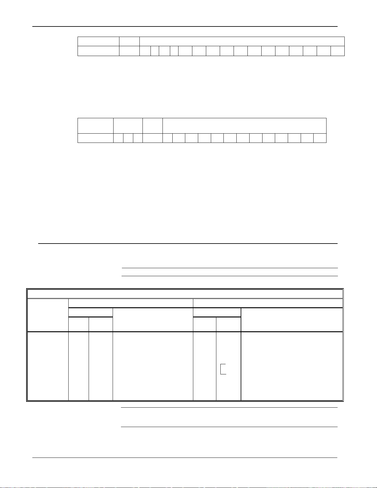
1.2 General Protocol Message Format
Figure 1-1 shows the various ROC and host protocol message formats.
General Message Format - Station “A”’ Polling Station “B” for Data/Action:
Destination (B) Source (A) Opcode
unit group unit group
d1 d2 d3 – – – – dm LSB MSB
General Message Format - Station “B” Responding to Station “A”:
Destination (A) Source (B) Opcode
unit group unit group
d1 d2 d3 – – – – dn LSB MSB
Figure 1-1. General Message Format
A message generally contains the following fields, in order from left to
right:
Field Description
Destination
Unit
Group
Source
Unit
Group
Specifies the address for the destination device.
Destination has two components:
Specifies the address for the source device. Source
has two components:
m Data B ytes CRC
n Data Bytes CRC
One-byte unit code for the station
address. The unit code for a ROC
address is user-configurable. For a host,
this must be a unique number. 0
represents “broadcast within group” and
is the “direct connect address.”
Indicates the group code for the station
address. This is user-configurable and
usually set to
.
One-byte unit code for the station
address. The unit code for a ROC
address is user-configurable. For a host,
this must be a unique number. 0
represents “broadcast within group” and
240 is the “direct connect address.”
Indicates the group code for the station
address. This is user-configurable and
1-2 Introduction Revised April 2020
Opcode
# of bytes
Data Bytes
Defines the operation code (opcode) action to
perform.
Indicates the number of bytes in the data byte field,
consisting of the path, desired opcode, number of
data bytes for the desired message, and the desired
message itself.
Contains messages of varying lengths, consisting of
the path, desired opcode, number of data bytes for
the desired message, and the message itself.
Page 9

ROC800L Protocol Specifications Manual
Field
Description
LSB
Least significant byte.
MSB
Data
Length
# of
bytes
13 5 1 0 7 0 1
m
Data
Length
# of
bytes
1 0 13 5 7
8
sec
min
hr
day
mo
yr
lyr
dwk l m
Messages are of flexible length. The first six data bytes are used for the
header information including: destination, source, opcode, and data
length (number of bytes). The length of a message equals the number of
data bytes transmitted plus eight overhead bytes (header information
and CRC).
The minimum message length is eight bytes if the number of data bytes
is zero (no data bytes transmitted). The maximum message length is 248
bytes (240 bytes of data). A “nibble” is a four-bit unit or half a byte.
Figure 1-2 provides examples of the messages exchanged if the host
requests the current time and date from ROC800L 13 of Group 5.
Host Request to ROC800L:
ROC Address Host Address Opcode
unit group unit group –
ROC800L Response to Host:
Most significant byte.
CRC
LSB MSB
Host Address ROC Address Opcode
unit group unit group –
Figure 1-2. Request/Response Example
Note: Addresses 240,240 and 0,x are reserved and should not be used.
1.3 Broadcast
ROC800L firmware version 1.00 and higher supports message
broadcasting. A broadcast message is an opcode that is sent to a unit of
0. In this case, all ROC800Ls with the group matching the request
accept the opcode and process it (regardless of the unit designation that
each ROC800L may have). The ROC800L does not respond to the
request.
For example, you may need to synchronize several ROC800Ls to the
same date and time. If the ROC800Ls were connected to the same radio
link and configured for the same group, a host could send an opcode 8
(Set Real-Time Clock) request to Unit 0 that would then set all of the
ROC800Ls configured in this group to the same date and time.
8 Data Bytes CRC
d1 d2 d3 – – – –- dn LSB MSB
Revised April 2020 Introduction 1-3
Page 10

ROC800L Protocol Specifications Manual
1.4 Calculating Data Offsets
A data byte offset is the offset (zero-based) from the beginning of a
transmit or receive buffer for the data items that comprise the opcode
data. The offset of the first data item is always 6 to allow for the header
information (bytes 0-5).
Certain data offset values are determined based on the ROC800L’s
configuration, such as for Opcode 0. The data byte offset for each item
may be calculated. To calculate the next data offset value, add the
previous offset value to the length of the previous data item:
Offset = Previous Offset + Length of Previous Data Item
1-4 Introduction Revised April 2020
Page 11

Chapter 2 – Opcodes
Opcode
Description
6
Sends ROC800L configuration.
7
Sends current time and date.
8
Sets new time and date.
10
Sends data from configurable opcode tables.
11
Sets data in configurable opcode tables.
17
Sets operator identification.
24
Stores and forwards.
50
Requests IO point position array.
100
Reads user-defined point information (Command 11)
105
Sends history point definition, min/max data, and current values for specified history point.
108
Sends tag and current history period for specified hi story points.
117
Sends specified number of weights and measur es eve nts sta rt ing at spec ifi ed event index.
This section details each ROC800L protocol opcode.
2.1 Opcode Overview
Table 2-1 summarizes each opcode. The tables in this section provide
detailed descriptions of the various opcodes used. For each opcode, a
brief description of the data bytes is provided. In some cases, the
number of data bytes returned for an opcode varies. For example,
Opcode 0, a full update, always returns certain input/output (I/O)
information along with optionally specified data.
Certain opcodes only send data and do not receive data back from the
ROC800L. For example, Opcode 8 requests the ROC800L to set the
time and date. The host transmits six to nine data bytes defining the new
time and date. The ROC800L resets the time and date and sends back an
acknowledgment in which the opcode is repeated, but no data bytes are
transmitted back. All acknowledgments are 8-byte messages that repeat
the opcode received, but do not transmit any data bytes.
ROC800L Protocol Specifications Manual
Opcode 255 is an error message indicator. This is also an 8-byte
message with no data bytes included. The opcode is set to 255 to
indicate the message received by the ROC800L had valid Cyclical
Redundancy Check (CRC), but contained invalid parameters. For
example, if a request was made for information on Analog Input #11,
but the ROC800L was configured for only eight analog inputs (0 to 7),
the ROC800L would respond back with the 8-byte message with the
opcode equal to 255 (error).
The number of analog inputs varies from ROC800L to ROC800L. This
variability is indicated by listing the first analog input and indicating the
remaining analog inputs by a period (“.”). In the following tables, a
period in either the Data byte(s) column or the Description of Data
column indicates a repetition of the proceeding item for the necessary
number of instances.
Table 2-1. Summary of Opcodes
Revised April 2020 Opcodes 2-1
Page 12

ROC800L Protocol Specifications Manual
Opcode
Description
118
Sends specified number of alarms starting at spe cifi ed alarm index.
119
Sends specified number of events starting at specif ied eve nt index.
135
Requests history point data.
136
Requests history index data. .
137
Requests history index for a day.
138
Requests daily and periodic history for a day.
166
Sets specified contiguous block of para meter s.
167
Sends specified contiguous block of parameters.
180
Sends specified parameters.
181
Sets specified parameters.
203
File transfer to and from ROC800L.
204
Sends specified number of events or weights and measures events starting at specified event index
(supporting 40-byte old and new value on parameter change)
206
Reads transaction history data
224
Sends Report-by-Exception (SRBX) message to host.
225
Acknowledges Report-by-Exception message from ROC800L.
255
Transmits ROC800L error messages in response to a request with invalid parameters or format.
Communi-
Host Request to ROC800L
ROC800L Response to Host
cation
Data
Data
Opcode
Offset
Length
Description of Data
Offset
Length
Description of Data
Opcode 6:
6 No data bytes
6 1 The system mode the unit is
7 2 Comm Port or Port Number that this
is 0.
9 1 Security Access Mode for the port
the request was received on.
2.2 Opcode 6, System Configuration
Opcode 6 obtains the current configuration of the ROC800L. This
opcode was introduced in version 1.00.
Table 2-2: Opcode 6, System Configuration
System
Configuration
currently operating in.
0 = Firmware Update Mode –
Extremely limited functionality is
available.
1 = Run Mode
request arrived on. This is not
defined if the above value (offset 6)
2-2 Opcodes Revised April 2020
Page 13

ROC800L Protocol Specifications Manual
Communi-
Host Request to ROC800L
ROC800L Response to Host
cation
Data
Data
Opcode
Offset
Length
Description of Data
Offset
Length
Description of Data
10 1 Logical Compatibility Status –
information.
11 1 Opcode 6 Revision
Types (offset 104 -220)
12
12
Reserved for Future Use [zeros
24 1 Type of ROC:
X = FB100
25 1 Contains the number of logical for
point type 60
26 1 Contains the number of logical for
point type 61
27
1
Contains the number of logical for
point type 62
28 1 Contains the number of logical for
point type 63
29 1 Contains the number of logical for
point type 64
30
1
Contains the number of logical for
point type 65
31 1 Contains the number of logical for
point type 66
32 1 Contains the number of logical for
point type 67
33 1 Contains the number of logical for
point type 68
34 1 Contains the number of logical for
point type 69
35 1 Contains the number of logical for
point type 70
Version 1.00
See [Point Type 91,Logical
0,Parameter 50]:
0 = 16 points per slot (160 bytes
total) – Compatibility Mode is 0 & 9
module slots max
1 = 16 points per slot (240 bytes
total) – Compatibility Mode is 0 & 14
module slots max. NOTE: The 15
module slot can not be used.
2 = 8 points per slot (224 bytes
total) – Compatibility
Mode is 1 & 27 module slots max.
See Opcode 50 for more
0 = Original (ROC800 Pre-1.00)
1 = Extended for Additional Point
th
returned]
1 = ROCPAC ROC 300 series
2 = FloBoss 407
3 = FlashPAC ROC 300 series
4 = FloBoss 503
5 = FloBoss 504
6 = ROC800 (827/809)
11=DL8000
15=ROC800L
Revised April 2020 Opcodes 2-3
Page 14

ROC800L Protocol Specifications Manual
Communi-
Host Request to ROC800L
ROC800L Response to Host
cation
Data
Data
Opcode
Offset
Length
Description of Data
Offset
Length
Description of Data
36 1 Contains the number of logical for
point type 71
37
1
Contains the number of logical for
point type 72
38 1 Contains the number of logical for
point type 73
39 1 Contains the number of logical for
point type 74
40 1 Contains the number of logical for
point type 75
41 1 Contains the number of logical for
point type 76
42 1 Contains the number of logical for
point type 77
43 1 Contains the number of logical for
point type 78
44 1 Contains the number of logical for
point type 79
45 1 Contains the number of logical for
point type 80
46 1 Contains the number of logical for
point type 81
47 1 Contains the number of logical for
point type 82
48 1 Contains the number of logical for
point type 83
49 1 Contains the number of logical for
point type 84
50 1 Contains the number of logical for
point type 85
51
1
Contains the number of logical for
point type 86
52 1 Contains the number of logical for
point type 87
53 1 Contains the number of logical for
point type 88
54
1
Contains the number of logical for
point type 89
55 1 Contains the number of logical for
point type 90
56 1 Contains the number of logical for
point type 91
57
1
Contains the number of logical for
point type 92
58 1 Contains the number of logical for
point type 93
59 1 Contains the number of logical for
point type 94
60 1 Contains the number of logical for
point type 95
61 1 Contains the number of logical for
point type 96
62 1 Contains the number of logical for
point type 97
2-4 Opcodes Revised April 2020
Page 15

ROC800L Protocol Specifications Manual
Communi-
Host Request to ROC800L
ROC800L Response to Host
cation
Data
Data
Opcode
Offset
Length
Description of Data
Offset
Length
Description of Data
63 1 Contains the number of logical for
point type 98
64
1
Contains the number of logical for
point type 99
65 1 Contains the number of logical for
point type 100
66 1 Contains the number of logical for
point type 101
67 1 Contains the number of logical for
point type 102
68 1 Contains the number of logical for
point type 103
69 1 Contains the number of logical for
point type 104
70 1 Contains the number of logical for
point type 105
71 1 Contains the number of logical for
point type 106
72 1 Contains the number of logical for
point type 107
73 1 Contains the number of logical for
point type 108
74 1 Contains the number of logical for
point type 109
75 1 Contains the number of logical for
point type 110
76 1 Contains the number of logical for
point type 111
77 1 Contains the number of logical for
point type 112
78
1
Contains the number of logical for
point type 113
79 1 Contains the number of logical for
point type 114
80 1 Contains the number of logical for
point type 115
81
1
Contains the number of logical for
point type 116
82 1 Contains the number of logical for
point type 117
83 1 Contains the number of logical for
point type 118
84
1
Contains the number of logical for
point type 119
85 1 Contains the number of logical for
point type 120
86 1 Contains the number of logical for
point type 121
87 1 Contains the number of logical for
point type 122
88 1 Contains the number of logical for
point type 123
89 1 Contains the number of logical for
point type 124
Revised April 2020 Opcodes 2-5
Page 16

ROC800L Protocol Specifications Manual
Communi-
Host Request to ROC800L
ROC800L Response to Host
cation
Data
Data
Opcode
Offset
Length
Description of Data
Offset
Length
Description of Data
90 1 Contains the number of logical for
point type 125
91
1
Contains the number of logical for
point type 126
92 1 Contains the number of logical for
point type 127
93 1 Contains the number of logical for
point type 128
94 1 Contains the number of logical for
point type 129
95 1 Contains the number of logical for
point type 130
96 1 Contains the number of logical for
point type 131
97 1 Contains the number of logical for
point type 132
98 1 Contains the number of logical for
point type 133
99 1 Contains the number of logical for
point type 134
100 1 Contains the number of logical for
point type 135
101 1 Contains the number of logical for
point type 136
102 1 Contains the number of logical for
point type 137
103 1 Contains the number of logical for
point type 138
Included if
104 1 Contains the number of logical for
point type 139
105 1 Contains the number of logical for
point type 140
106 1 Contains the number of logical for
point type 141
107
1
Contains the number of logical for
point type 142
108 1 Contains the number of logical for
point type 143
109 1 Contains the number of logical for
point type 144
110 1 Contains the number of logical for
point type 145
111 1 Contains the number of logical for
point type 146
112 1 Contains the number of logical for
point type 147
113
1
Contains the number of logical for
point type 148
114
1
Contains the number of logical for
point type 149
115 1 Contains the number of logical for
point type 150
Opcode 6
Revision
(offset 11) ≥
1
2-6 Opcodes Revised April 2020
Page 17

ROC800L Protocol Specifications Manual
Communi-
Host Request to ROC800L
ROC800L Response to Host
cation
Data
Data
Opcode
Offset
Length
Description of Data
Offset
Length
Description of Data
116 1 Contains the number of logical for
point type 151
117 1 Contains the number of logical for
point type 152
118 1 Contains the number of logical for
point type 153
119 1 Contains the number of logical for
point type 154
120 1 Contains the number of logical for
point type 155
121
1
Contains the number of logical for
point type 156
122 1 Contains the number of logical for
point type 157
123 1 Contains the number of logical for
point type 158
124 1 Contains the number of logical for
point type 159
125 1 Contains the number of logical for
point type 160
126 1 Contains the number of logical for
point type 161
127
1
Contains the number of logical for
point type 162
128 1 Contains the number of logical for
point type 163
129 1 Contains the number of logical for
point type 164
130 1 Contains the number of logical for
point type 165
131 1 Contains the number of logical for
point type 166
132 1 Contains the number of logical for
point type 167
133 1 Contains the number of logical for
point type 168
134
1
Contains the number of logical for
point type 169
135 1 Contains the number of logical for
point type 170
136 1 Contains the number of logical for
point type 171
137 1 Contains the number of logical for
point type 172
138 1 Contains the number of logical for
point type 173
139 1 Contains the number of logical for
point type 174
140 1 Contains the number of logical for
point type 175
Revised April 2020 Opcodes 2-7
Page 18

ROC800L Protocol Specifications Manual
Communi-
Host Request to ROC800L
ROC800L Response to Host
cation
Data
Data
Opcode
Offset
Length
Description of Data
Offset
Length
Description of Data
141 1 Contains the number of logical for
point type 176
142 1 Contains the number of logical for
point type 177
143 1 Contains the number of logical for
point type 178
144 1 Contains the number of logical for
point type 179
145 1 Contains the number of logical for
point type 180
146
1
Contains the number of logical for
point type 181
147 1 Contains the number of logical for
point type 182
148 1 Contains the number of logical for
point type 183
149 1 Contains the number of logical for
point type 184
150 1 Contains the number of logical for
point type 185
151 1 Contains the number of logical for
point type 186
152
1
Contains the number of logical for
point type 187
153 1 Contains the number of logical for
point type 188
154 1 Contains the number of logical for
point type 189
155 1 Contains the number of logical for
point type 190
156 1 Contains the number of logical for
point type 191
157 1 Contains the number of logical for
point type 192
158 1 Contains the number of logical for
point type 193
159
1
Contains the number of logical for
point type 194
160 1 Contains the number of logical for
point type 195
161 1 Contains the number of logical for
point type 196
162 1 Contains the number of logical for
point type 197
163 1 Contains the number of logical for
point type 198
164 1 Contains the number of logical for
point type 199
165 1 Contains the number of logical for
point type 200
2-8 Opcodes Revised April 2020
Page 19

ROC800L Protocol Specifications Manual
Communi-
Host Request to ROC800L
ROC800L Response to Host
cation
Data
Data
Opcode
Offset
Length
Description of Data
Offset
Length
Description of Data
166 1 Contains the number of logical for
point type 201
167 1 Contains the number of logical for
point type 202
168 1 Contains the number of logical for
point type 203
169 1 Contains the number of logical for
point type 204
170 1 Contains the number of logical for
point type 205
171
1
Contains the number of logical for
point type 206
172 1 Contains the number of logical for
point type 207
173 1 Contains the number of logical for
point type 208
174 1 Contains the number of logical for
point type 209
175 1 Contains the number of logical for
point type 210
176 1 Contains the number of logical for
point type 211
177
1
Contains the number of logical for
point type 212
178 1 Contains the number of logical for
point type 213
179 1 Contains the number of logical for
point type 214
180 1 Contains the number of logical for
point type 215
181 1 Contains the number of logical for
point type 216
182 1 Contains the number of logical for
point type 217
183 1 Contains the number of logical for
point type 218
184
1
Contains the number of logical for
point type 219
185 1 Contains the number of logical for
point type 220
186 1 Contains the number of logical for
point type 221
187 1 Contains the number of logical for
point type 222
188 1 Contains the number of logical for
point type 223
189 1 Contains the number of logical for
point type 224
190 1 Contains the number of logical for
point type 225
Revised April 2020 Opcodes 2-9
Page 20

ROC800L Protocol Specifications Manual
Communi-
Host Request to ROC800L
ROC800L Response to Host
cation
Data
Data
Opcode
Offset
Length
Description of Data
Offset
Length
Description of Data
191 1 Contains the number of logical for
point type 226
192 1 Contains the number of logical for
point type 227
193 1 Contains the number of logical for
point type 228
194 1 Contains the number of logical for
point type 229
195 1 Contains the number of logical for
point type 230
196
1
Contains the number of logical for
point type 231
197 1 Contains the number of logical for
point type 232
198 1 Contains the number of logical for
point type 233
199 1 Contains the number of logical for
point type 234
200 1 Contains the number of logical for
point type 235
201 1 Contains the number of logical for
point type 236
202
1
Contains the number of logical for
point type 237
203 1 Contains the number of logical for
point type 238
204 1 Contains the number of logical for
point type 239
205 1 Contains the number of logical for
point type 240
206 1 Contains the number of logical for
point type 241
207 1 Contains the number of logical for
point type 242
208 1 Contains the number of logical for
point type 243
209
1
Contains the number of logical for
point type 244
210 1 Contains the number of logical for
point type 245
211 1 Contains the number of logical for
point type 246
212 1 Contains the number of logical for
point type 247
213 1 Contains the number of logical for
point type 248
214 1 Contains the number of logical for
point type 249
215 1 Contains the number of logical for
point type 250
2-10 Opcodes Revised April 2020
Page 21

Communi-
Host Request to ROC800L
ROC800L Response to Host
cation
Data
Data
Opcode
Offset
Length
Description of Data
Offset
Length
Description of Data
216 1 Contains the number of logical for
point type 251
217 1 Contains the number of logical for
point type 252
218 1 Contains the number of logical for
point type 253
219 1 Contains the number of logical for
point type 254
220 1 Contains the number of logical for
point type 255
2.3 Opcode 7, Read Real-time Clock
Version
Description
1.00
Introduced
Opcode 7
Communi-
Host Request to ROC800L
ROC800L Response to Host
Cation
Data
Data
Opcode
Offse
t
Length
Description of Data
Offset
Length
Description of Data
Opcode 7:
No data bytes.
6 1 Current second [UINT8]
7 1
Current minute [UINT8]
8 1
Current hour [UINT8]
9 1
Current day [UINT8]
10
1
Current month [UINT8]
11
2
Current year [UINT16]
13
1
Current day of week [UINT8]
1=Sunday 7=Saturday
Refer to Table 2–3 when using Opcode 7 to return the current time and
date, the number of years since the last leap year, and the day of week.
ROC800L Protocol Specifications Manual
Send Current
Time and
Date
Note: You can also read the time/date by specifying Point Type 136
(ROC Clock) or Opcode 167 (Request Single Point Parameters).
Table 2–3. Opcode 7, Read Real-time Clock
Revised April 2020 Opcodes 2-11
Page 22

ROC800L Protocol Specifications Manual
Version
Description
1.00
Introduced
Opcode 8
Communi-
Host Request to ROC800L
ROC800L Response to Host
Cation
Data
Data
Opcode
Offset
Length
Description of Data
Offset
Length
Description of Data
Opcode 8:
Set
6 1 Current seconds [UINT8]
No data bytes.
Current Time
7 1 Current minutes [UINT8]
Time and date are set and
acknowledgment sent back.
and Date
8 1 Current hour [UINT8]
9 1
Current day [UINT8]
10
1
Current month [UINT8]
11
2
Current year [UINT16]
Opcode 10
Communi-
Host Request to ROC800L
ROC800L Response to Host
Cation
Data
Data
Opcode
Offse
t
Length
Description of Data
Offset
Length
Description of Data
Opcode 10:
6 1 Table Number (0-15)
6 1 Table Number (0-15)
7 1 Starting Table Location (0-
43)
7 1 Starting Table Location (0-43)
8 1 Number of Table Locations
(1-44)
8 1 Number of Table Locations (1-44)
9 4
Table Version Number [float]
13
x
Data
2.4 Opcode 8, S et Real-tim e Clo c k
Opcode 8 is the only way to set the real-time clock. The ROC800L
calculates the current day of the week. When you set the clock, the
microseconds in the ROC800L zero out.
Table 2–4. Opcode 8, Set Real-time Clock
2.5 Op cod e 1 0, R ead Con fig urable Opcode Point Data
Opcode 10 reads data defined by Point Type 99 (Configurable Opcode).
The value of the starting table location plus the number of table
locations must be less than or equal to 44.
Table 2–5. Opcode 10, Read Configurable Opcode Point Data
Send Data
from
Configurable
Opcode
Tables
2-12 Opcodes Revised April 2020
Page 23

ROC800L Protocol Specifications Manual
Version
Description
1.00
Introduced
Opcode 11
Host Request to ROC800L
ROC800L Response to Host
Data
Data
Offset
Length
Offset
Length
Opcode 11:
6 1 Table Number (0-7) –
RegFlo)
No data bytes.
7 1 Starting Table Location (0-
43)
Acknowledgment sent back.
8 1 Number of Table Locations
(1-44)
9 x Data
Version
Description
1.00
Introduced
2.6 Op cod e 1 1, Wri t e Config urable Opcode Point Data
Opcode 11 writes data defined by Point Type 99 (Configurable
Opcode). The value of the starting table location plus the number of
table locations must be less than or equal to 44.
Table 2–6. Opcode 11, Write Configurable Opcode Point Data
Communi-
cation
Opcode
Description of Data
Description of Data
Set Data in
Configurable
Opcode
Tables
(ROC300-Series and
FloBoss 407)
Table Number (0-3) –
(FloBoss 100-Series,
FloBoss 500-Series, and
2.7 Op cod e 1 7, Log in Request
Opcode 17 sets an operator identification code for the communications
port through which communications are occurring. The operator
identification is logged with an event, indicating the operator
responsible for creating the event. The ROC800L provides a default
operator identification for each communications port.
Once you set the operator identification, it remains set until changed by:
Revised April 2020 Opcodes 2-13
Subsequent Opcode 17 requests;
ROC800L initialized by a cold hard start;
Firmware upgrade; or
Timeout.
Page 24

ROC800L Protocol Specifications Manual
Opcode 17
Communi-
Host Request to ROC800L
ROC800L Response to Host
cation
Data
Description of Data
Data
Description of Data
Opcode
Offse
t
Length
Offset
Length
Opcode 17:
ID
6 3 Operator ID [AC3]
Acknowledgment sent back without
on.
9 2 Password [UINT16]
11
1
Access Level [UINT8]
Opcode 17:
letters
6 3 Operator ID [AC3]
Acknowledgement sent back without
data
9 2 Password [UINT16]
11
6
Logout String [AC6]
Version
Description
1.00
Introduced
Table 2–7. Opcode 17, Login Request
Set Operator
Note: Access
Level only
sent if
Security
Mode (95, x,
44) is set to 2
where x =
the logical of
the port the
request is
being made
Logout
Request
Note: Logout
string is the
ASCII string
“LOGOUT” in
all capital
data.
2.8 Opcode 24, Store a nd Forward
2-14 Opcodes Revised April 2020
Opcode 24 defines the requested store and forward action through up to
three intermediate ROC800Ls to the final destination ROC800L. Refer
to Chapter 7, Device-to-Device Communications, for details on how this
opcode works.
Page 25

Opcode 24
Communi-
Host Request to ROC800L
ROC800L Response to Host
Data
Data
Offset
Length
Offset
Length
Opcode 24:
6
1
Host Address
No response to host until
Destination ROC800L.
7
1
Host Group
8
1
1st Destination Address
9 1
1st Destination Group
10
1
2nd Destination Address
11
1
2nd Destination Group
12
1
3rd Destination Address
13
1
3rd Destination Group
14
1
4th Destination Address
15
1
4th Destination Group
16
1
Desired Opcode
17
1
Number of data bytes for
the desired Opcode
18
x
Opcode request data (if
any)
Version
Description
1.00
Introduced
Opcode 50
Communi-
Host Request to ROC800L
ROC800L Response to Host
Cation
Data
Data
Opcode
Offset
Length
Description of Data
Offset
Length
Description of Data
Opcode 50:
Type.
6 1 Which I/O data to send (0 =
6
160
I/O Point Types or Logical Numbers
of response
cation
Opcode
ROC800L Protocol Specifications Manual
Table 2–8. Opcode 24, Store and Forward
Description of Data
Description of Data
Store and
Forward
2.9 Opcode 50, Request I/O Point Position
Opcode 50 is used to request either the type or the logical number of all
the I/O points in the ROC800L, returned in the order of their physical
location in the ROC800L. The system (diagnostic) inputs are also
included.
message returns from Final
Send I/O
Point Type or
Logical
Number
associated
with the Point
2.10 Opcode 100, Access User-defined Information
Revised April 2020 Opcodes 2-15
Table 2-9. Opcode 50, Request I/O Point Position
I/O Point Type, 1 = I/O
Logical Number)
240
224
See Opcode 6 (offset 10) for length
Opcode 100 reads user-defined point type information.
Page 26

ROC800L Protocol Specifications Manual
Version
Description
1.00
Introduced (Command 11)
Opcode 100
Communi-
Host Request to ROC800L
ROC800L Response to Host
Cation
Data
Data
Opcode
Offset
Length
Description of Data
Offset
Length
Description of Data
Get Point
Information
6 1 Command (11)
6 1 Command (11)
7 1 Start Point # (0 – 255)
7 1 Start Point # (0 – 255)
Retrieve
8 1 # Points (0 – 245)
8 1 # Points (0 – 245)
9 1
Type of Point Type
0 – 7 User Program
253 – User Defined
254 – ROC Point
Type
255 – No Point Type
(Above repeated as
necessary)
Version
Description
1.00
Introduced
Enumeration
Historical archive method.
128
129
134
Archived every hour (Totalize)
Opcode 105
Communi-
Host Request to ROC800L
ROC800L Response to Host
cation
Data
Data
Opcode
Offset
Length
Description of Data
Offset
Length
Description of Data
Opcode 105:
6 1 History Segment (0 – 10)
6
1
History Segment (0 – 10)
7 1 History point number
7
1
Historical point number
Table 2-10. Opcode 100, Access User-defined Information
Type
information
about point
types.
2.11 Opcode 105, Request Today’s and Yesterday’s Min/Max Values
Opcode 105 retrieves the occurrence of today’s and yesterday’s
minimum and maximum values.
Archived every hour (Average)
Archived every hour (Accumulated)
130 Archived every hour (Current)
67
65
0 Not defined.
Table 2–11. Opcode 105, Request Today’s and Yesterday’s Min/Max Values
Timestamp logged with FST-controlled timestamp.
Timestamp is a TIME [UINT32] representing the number of
seconds elapsed since 12:00AM Jan 1, 1970. Use FST
command WTM (Write Current Time to History)
Database value logged when directed by FST command
WDB (Write Results Register Value to History)
Send History
2-16 Opcodes Revised April 2020
Page 27

Opcode 105
Communi-
Host Request to ROC800L
ROC800L Response to Host
cation
Data
Data
Opcode
Offset
Length
Description of Data
Offset
Length
Description of Data
Point Defini-
tion, Min and
8 1
Historical Archival Method Ty pe
9 1
Point type
10
1
Point/Logic number
11
1
Parameter number
12
4
Current value [float]
16
4
Minimum value since contract hour
[float]
20
4
Maximum value since contract hour
[float]
24
5
Time of minimum value occurrence
1970.
Seconds, minutes, hour, day, and
month
29
5
Time of maximum value
1970.
Seconds, minutes, hour, day, and
month 34
4
Minimum value yesterday [float]
38
4
Maximum value yesterday [float]
42
5
Time of yesterday’s min value
1970.
Seconds, minutes, hour, day and
month
47
5
Time of yesterday’s max value
1970.
Seconds, minutes, hour, day, and
month
52
4
Value during last completed period
[float]
Max Data,
and Current
Value for
Specified
History Point
ROC800L Protocol Specifications Manual
Note: This is a UINT32 (4 bytes)
and contains the number of
seconds since 12:00AM Jan 1,
occurrence.
Note: This is a UINT32 (4 bytes)
and contains the number of
seconds since 12:00AM Jan 1,
occurrence.
Note: This is a UINT32 (4 bytes)
and contains the number of
seconds since 12:00AM Jan 1,
2.12 Opcode 108, Request History Tag and Periodic Index
Revised April 2020 Opcodes 2-17
occurrence.
Note: This is a UINT32 (4 bytes)
and contains the number of
seconds since 12:00AM Jan 1,
Page 28

ROC800L Protocol Specifications Manual
Version
Description
1.00
Introduced
Opcode 108
Communi-
Host Request to ROC800L
ROC800L Response to Host
cation
Data
Description of Data
Data
Description of Data
Opcode
Offset
Length
Offset
Length
Opcode 108:
Point(s)
6 1 History Segment (0 – 10)
6
1
History Segment (0 – 10)
7 1 # of historical points
specified
7
1
# of historical points specified
8 1 Historical point (0 – 199)
8
2
Periodic Index (common among
all history points in segment)
. (above repeated as
necessary 20 maximum)
(repeated
1
History point
10
Tag [AC10]
Version
Description
1.00
Introduced
Opcode 117
Communi-
Host Request to ROC800L
ROC800L Response to Host
cation
Data
Data
Opcode
Offset
Length
Description of Data
Offset
Length
Description of Data
Opcode 117:
Event Index
6 1 # of events requested (max
10) *SEE NOTE BELOW
6 1 Number of events being sent
7 2 Starting Event Log index
7 2 Starting Event Log index
9 2
Current Event Log index
11
22
Event Data
.
(above repeated as necessary)
Event Data
Format
The event log stores the last 1000 event entries. Each event consists of
Opcode 108 sends the tag and history period for specified history points,
up to a maximum of 20 history points. All points must be within a
single segment.
Table 2–12. Opcode 108, Request History Tag and Periodic Index
Send Tag
and
Current
History
Period for
Specified
History
as
necessary)
2.13 Opcode 117, Request Weights and Measures Event Data
Opcode 117 requests event data from the Event Log in the ROC800L.
The Weights and Measures Event Log consists of 1000 events. Each
event consistes of 22 bytes, organized according to one of the formats
described below.
Table 2–13. Opcode 117, Request Weights and Measures Event Data
Send
Specified
Number of
Events
Starting with
the Specified
Note: If no events are requested, the ROC800L does not return event
data.
22 bytes and has the following general format:
2-18 Opcodes Revised April 2020
Page 29

ROC800L Protocol Specifications Manual
Description:
Type
Time
Event Specific Data
Byte:
0 1 2 3 4 5 6 7 8 9 10
11
12
13
14
15
16
17
18
19
20
21
Weights and Measures
Event Type
Identifies what type of event is stored in the event specific data. Valid
Event
the following format:
System Event
A system event is an event the ROC800L logs internally. The event data
values are:
0 - No Event
1 - Parameter Change Event
2 - System Event
4 - User Event
Parameter Change
Logs any time a user makes a change to any TLP. The event data has
Description: Operator ID TLP Data
Type
Byte: 5 6 7 8 9 10 11 12 13 14 15 16 17 18 19 20 21
New Value Old Value Spare
Operator ID: Identifies who made the change.
TLP: Identifies what parameter was changed.
Data Type: Identifies the type of data stored in the new value and
old value fields. Valid values are:
0 - BIN
1 - INT8
2 - INT16
3 - INT32
4 - UINT8
5 - UINT16
6 - UINT32
7 - FL
8 - TLP
9 - AC (3 bytes)
10 - AC (7 bytes)
11 - AC (10 bytes)
12 - AC (12 bytes)
13 - AC (20 bytes)
14 - AC (30 bytes)
15 - AC (40 bytes)
16 – DOUBLE
17 – TIME
New Value: New value of the changed parameter. If the data size is
larger than 4 bytes, the new value extends beyond its four-byte field
and into the old value and spare fields.
Old Value: Old value of the changed parameter. The old value
always starts at byte offset 16. If the data type is too large to store
both old value and new value, only the new value is stored.
has the following format:
Revised April 2020 Opcodes 2-19
Page 30
ROC800L Protocol Specifications Manual
User Event
Version
Description
1.00
Introduced
Opcode 118
Communi-
Host Request to ROC800L
ROC800L Response to Host
cation
Data
Data
Opcode
Offse
t
Length
Description of Data
Offset
Length
Description of Data
Opcode 118:
Alarm index.
6 1 # of alarms requested (max
10) *SEE NOTE BELOW
6 1 Number of alarms being sent
7 2 Starting Alarm Log index
7 2 Starting Alarm Log index
9 2
Current Alarm Log index
11
23
Alarm Data
.
(above repeated as necessary)
Description: Code Description
Byte: 5 6 7 8 9 10 11 12 13 14 15 16 17 18 19 20 21
Code: More specifically defines the type of event that occurred. See
Opcode 119 for list of event codes.
Description: Textual description of the alarm.
An event a logged-in user causes. The data has the following format:
Description:
Byte: 5 6 7 8 9 10 11 12 13 14 15 16 17 18 19 20 21
Operator
Id
Code
Operator ID: Identifies who made the change.
Code: More specifically defines the type of event that occurred. See
Opcode 119 for list of event codes.
Description: Textual description of the alarm.
Timestamp
The timestamp for the alarm represents the time the alarm was logged.
The timestamp is a TIME [UINT32] representing the number of
seconds that have elapsed since 12:00 a.m. Jan. 1, 1970.
Description
Send
Specified
Number of
Alarms
Starting
With
Specified
2.14 Opcode 118, Request Alarm Data
Opcode 118 requests alarm data from the ROC800L’s Alarm Log.
Table 2–14. Opcode 118, Request Alarm Data
Note If no alarms are requested, the ROC800L does not return alarm
data.
2-20 Opcodes Revised April 2020
Page 31

ROC800L Protocol Specifications Manual
Alarm Type
The alarm type (byte 0) is a packed one-byte field that also includes
Alarm Data
The alarm log stores the last 450 alarm entries. Each alarm consists of
23 bytes and has the following general format:
Description Type Time Alarm-specific Data
Byte: 0 1 2 3 4 5 6 7 8 9 10 11 12 13 14 15 16 17 18 19 20 21 22
Alarm Type
The alarm type (byte 0) is a packed one-byte field that also includes
information identifying if the alarm indicates a set or clear condition,
and if the alarm is an SRBX alarm.
Byte Breakdown
information identifying if the alarm indicates a set or clear condition,
and if the alarm is an SRBX alarm. It has the following format:
Description SRBX Condition Type
Bit: 7 6 5 4 3 2 1 0
SRBX (most significant bit): Indicates whether the alarm was an
SRBX alarm. An SRBX allows the ROC800L to notify a host about
certain alarm conditions. The host may be notified when an alarm is
either set or cleared. Refer to Chapter 6. Valid values are:
0 - No SRBX
1 - SRBX issued
Condition (bit 6): Indicates if the alarm is being set or cleared.
Valid values are:
0 - Cleared
1 – Set
Type (bits 5-0): Identifies what type of alarm is stored. See Alarm-
specific Data for byte usage (5-22) of each type. Valid values are:
0 - No Alarm
1 - Parameter Alarm
2 - FST Alarm
3 - User Text Alarm
4 - User Value Alarm
Time
Bytes 1 to 4 provide the timestamp for the alarm, which is the time the
alarm was logged. The timestamp is a TIME [UINT32] which
represents the number of seconds that have elapsed since 12:00 a.m.
Jan. 1, 1970.
Alarm-specific
Data
For each alarm type, bytes 5 to 22 provide an alarm description and
value as appropriate:
Revised April 2020 Opcodes 2-21
Page 32

ROC800L Protocol Specifications Manual
Parameter Alarm
This type of alarm is typically generated by a parameter reaching a
particular value. The data for this particular alarm has the following
format:
Description: Code TLP Alarm Description Value
Byte: 5 6 7 8 9 10 11 12 13 14 15 16 17 18 19 20 21 22
Code: Reason why the alarm was logged. Some codes have meaning
only for certain TLPs. Valid values are:
0 - Low Alarm
1 - Low Low Alarm
2 - High Alarm
3 - High High Alarm
4 - Rate Alarm
5 - Status Change
6 - Point Fail
7 - Scanning Disabled
8 - Scanning Manual
9 - Redundant Total Counts
10 - Redundant Flow Register
11 - No Flow Alarm
12 - Input Freeze Mode
13 - Sensor Communication Failure
14 - 485 Communication Failure
15 - Off Scan Mode
16 - Manual Flow Inputs.
17 - Meter Temperature Failure Alarm
18 - Compressibility Calculation Alarm
19 - Sequence Out of Order
20 - Phase Discrepancy
21 - Pulse Synchronizat ion F ailur e
22 - Frequency Discrepancy
23 - Pulse Input One Failure
24 - Pulse Input Two Failure
25 - Pulse Output Buffer Overrun
26 - Pulse Output Buffer Warning
27 - Relay Fault
28 - Relay Failure
29 - Static Pressure Low Limited
30 - Temperature Low Limited
31 - Analog Output Readback Errror
32 - Bad Level A Pulse Stream
33 - Marker Pulse Stream
34 - Orifice Diamete Range Alarm
35 - Pipe Diameter Range Alarm
36 - Beta Range Alarm
37 - Reynolds Number Range Alarm
38 - Non Convergence Alarm
TLP: Parameter that caused the alarm. In some situations only the
Type and Logical of the TLP have meaning.
Alarm Description: Short textual description of the alarm.
2-22 Opcodes Revised April 2020
Page 33

ROC800L Protocol Specifications Manual
User Text
Alarm
Alarm that was logged by a User C++ program. The data for this
User Value
Alarm
Alarm that was logged by a User C++ program. The data for this
Version
Description
1.00
Introduced
Value: Value of the specified TLP when alarm was logged. Data is a
floating-point value regardless of the type associated with the
parameter for specified TLP.
FST Alarm
Alarm that was logged from an FST. The data for this particular alarm
has the following format:
Description: FST # Alarm Description Value
Byte: 5 6 7 8 9 10 11 12 13 14 15 16 17 18 19 20 21 22
FST #: Indicates which running FST logged the alarm.
Alarm Description: Short textual description of the alarm
Value: Floating point value associated with alarm.
particular alarm has the following format:
Description: Alarm Description
Byte: 5 6 7 8 9 10 11 12 13 14 15 16 17 18 19 20 21 22
Alarm Description: Short textual description of the alarm
particular alarm has the following format:
Description: Alarm Description Value
Byte: 5 6 7 8 9 10 11 12 13 14 15 16 17 18 19 20 21 22
Alarm Description: Short textual description of the alarm.
Value: Floating point value associated with alarm.
2.15 Opcode 119, Request Event Data
Opcode 119 requests event data from ROC800L’s Event Log. The
Event Log consists of a maximum of 450 events. Each event consists of
22 bytes, organized according to one of the five formats described
below.
Revised April 2020 Opcodes 2-23
Page 34

ROC800L Protocol Specifications Manual
Opcode 119
Communi-
Host Request to ROC800L
ROC800L Response to Host
cation
Data
Data
Opcode
Offset
Length
Description of Data
Offset
Length
Description of Data
Opcode 119:
Index
6 1 # of events requested (max
10) *SEE NOTE BELOW
6 1 Number of events being sent
7 2 Starting Event Log index
7 2 Starting Event Log index
9 2
Current Event Log index
11
22
Event Data
.
(above repeated as necessary)
Byte:
0 1 2 3 4 5 6 7 8 9 10
11
12
13
14
15
16
17
18
19
20
21
Event Type
The event type identifies what type of event is stored in the event
Event
Table 2–15. Opcode 119, Request Event Data
Send
Specified
Number of
Events
Starting
with the
Specified
Event
Note: If no events are requested, the ROC800L does not return event
data.
Event Data
Description: Type Time Event Specific Data
Parameter Change
Description: Operator ID TLP Data
Byte: 5 6 7 8 9 10 11 12 13 14 15 16 17 18 19 20 21
2-24 Opcodes Revised April 2020
The event log stores the last 450 event entries. Each event consists of 22
bytes and has the following general format:
specific data. Valid values are:
0 - No Event
1 - Parameter Change Event
2 - System Event
3 - FST Event
4 - User Event
5 - Power Lost Event
6 - Clock Set Event
7 - Calibrate Verify Event
A Parameter Change event is logged any time a user makes a change to
any TLP. The data for the event has the following format::
New Value Old Value Spare
Type
Operator ID: Identifies who made the change.
TLP: Identifies what parameter was changed.
Data Type: Identifies the type of data stored in the new value and
old value fields. Valid values are:
Page 35

ROC800L Protocol Specifications Manual
0 - BIN
1 - INT8
2 - INT16
3 - INT32
4 - UINT8
5 - UINT16
6 - UINT32
7 - FL
8 - TLP
9 - AC (3 bytes)
10 - AC (7 bytes)
11 - AC (10 bytes)
12 - AC (12 bytes)
13 - AC (20 bytes)
14 - AC (30 bytes)
15 - AC (40 bytes)
16 – DOUBLE
17 – TIME
New Value: New value of the changed parameter. New value will
extend beyond its four byte field and into the old value and spare
fields if the data size is larger than 4 bytes.
Old Value: Old value of the changed parameter. The old value
always starts at byte offset 16. If the data type is too large to store
both old value and new value, only the new value will be stored.
System Event
A System event logs internally in the ROC800L. The data for the event
has the following format:
Description: Code Description
Byte: 5 6 7 8 9 10 11 12 13 14 15 16 17 18 19 20 21
Code: More specifically defines the type of event that occurred.
Valid values are:
144 - Initialization Sequence
145 - All Power Removed
146 - Initialize from defaults .
147 - ROM CRC Error
148 - Database Initialization
150 - Program Flash
151 – Weights and Measures Switch Enabled
152 – Weights and Measures Switch Disabled
153 – Parameter access lookup failed
154 - Smart Module Inserted
155 - Smart Module Removed
200 - Clock Set
248 - Text Message
249 - Download Configuration
250 - Upload Configuration
251 - Calibration Timeout
252 - Calibration Cancel
253 - Calibration Success
254 - MVS Reset to Factory Defaults
Revised April 2020 Opcodes 2-25
Page 36

ROC800L Protocol Specifications Manual
Description:
FST #
Value
Description
Spare
Byte:
5 6 7 8 9
10
11
12
13
14
15
16
17
18
19
20
21
Event
Description: Textual description of the alarm.
FST Event
An FST event is logged by an FST. The data for the event has the
following format:
FST #: Identifies which FST logged the event.
Value: Floating point value associated with event.
Description: Textual description of the event.
User Event
A User event is logged by the action of a logged in user. The data for
the event has the following format:
Description: Operator Id Code Description
Byte: 5 6 7 8 9 10 11 12 13 14 15 16 17 18 19 20 21
Operator ID: Identifies who made the change.
Code: More specifically defines the type of event that occurred.
Valid values are:
144 - Initialization Sequence
145 - All Power Removed
146 - Initialize from defaults .
147 - ROM CRC Error
148 - Database Initialization
150 - Program Flash
151 – Weights and Measures Switch Enabled
152 – Weights and Measures Switch Disabled
153 – Parameter access lookup failed
154 - Smart Module Inserted
155 - Smart Module Removed
200 - Clock Set
248 - Text Message
249 - Download Configuration
250 - Upload Configuration
251 - Calibration Timeout
252 - Calibration Cancel
253 - Calibration Success
254 - MVS Reset to Factory Defaults
Description: Textual description of the alarm.
Power Lost
A Power Lost event is logged when power to the ROC800L has been
lost. The data for the event has the following format:
Description: Time Not Used
2-26 Opcodes Revised April 2020
Page 37

ROC800L Protocol Specifications Manual
Clock Set
Event
A Clock Set event is logged when the time is set on the ROC800L. The
Calibrate Verify
Event
A Calibrate Verify event is logged any time a user tests the calibration
Timestamp
The timestamp for the alarm represents the time the alarm was logged.
Version
Description
1.00
Introduced
Byte: 5 6 7 8 9 10 11 12 13 14 15 16 17 18 19 20 21
Time: Time that power to the unit was lost.
data for the event has the following format
Description: Time Not Used
Byte: 5 6 7 8 9 10 11 12 13 14 15 16 17 18 19 20 21
Time: Identifies the time on the ROC800L was set to.
of an I/O point.
Description: Operator ID TLP Raw Value Calibrated Value Spare
Byte: 5 6 7 8 9 10 11 12 13 14 15 16 17 18 19 20 21
Operator ID: Identifies who tested the calibration.
TLP: Identifies what parameter was tested.
Raw Value: Value of input before calibration was applied. Data
type is float.
Calibrated Value: Value of input after calibration was applied.
Data type is float.
The timestamp is a TIME [UINT32] which represents the number of
seconds that have elapsed since 12:00 a.m. Jan. 1, 1970.
2.16 Opcode 135, Request Single History Point Data
Opcode 135 requests a specified number of history data values for a
single history point, starting at a specified history index.
The history segment indicates where data is requested, according to the
following format:
0 = General History #0
1 = General History #1
2 = General History #2
.
.
.
9 = General History #9
10 = General History #10
The history point can be referenced by point number only as zero (0) –
x, where x is the number of history points defined for a History
Revised April 2020 Opcodes 2-27
Page 38

ROC800L Protocol Specifications Manual
Opcode 135
Communi-
Host Request to ROC800L
ROC800L Response to Host
Cation
Data
Data
Opcode
Offset
Length
Description of Data
Offset
Length
Description of Data
Opcode 135:
6 1 History Segment (0-10)
6 1 History Segment (0-10)
7 1 Point number (0-(# of history
7 1 Point number (0-(# of history points
8 1 Type of History (Minute – 0,
Daily Time Stamps – 4)
8 2 Current history segment index
9 2 Starting history segment
history point – 1)}
10
1
# of values being sent
11
1
# of values requested (max
60) *SEE NOTE BELOW
11
4
1st history value
. (above repeat as necessary)
Segment. For each history segment, you can retrieve three types of
possible history: Minute (0), Periodic (1), and Daily (2).
You can also retrieve the Periodic (3) and Daily (4) timestamps.
The starting history index specifies the record from which the history
values start:
Minute History: 0 – 60.
Periodic History: 0 – (#periodic entries in history point – 1) (24
hours per day repeated for a maximum of 35 days).
Daily History: 0 – (#daily entries in history point – 1).
Opcode 135 returns the history values for the requested history point
from the starting history index and continues until it completes the
requested number of indexes. To read timestamps, specify the value in
“Type of History”.
The timestamp is a TIME [UINT32] representing the number of seconds
elapsed since 12:00 a.m. Jan. 1, 1970. This can be thought of as column
addressing.
Send
Specified #
of History
Data for
Specified
History Point
Starting at
Specified
History Index
Table 2–16. Opcode 135, Request Single History Point Data
points for history segment –
1))
Periodic – 1, or Daily – 2,
Periodic Time Stamps – 3;
index {Minute 0 – 59,
Periodic 0 - (#periodic
entries in history point – 1),
or Daily 0 - (#daily entries in
for history segment – 1))
2.17 Opcode 136, Request Mutiple History Point Data
2-28 Opcodes Revised April 2020
Note: If no events are requested, the ROC800L does not return history
values.
Opcode 136 requests a specified number of history data values for a
specified starting history index for a specified number of time periods,
Page 39

ROC800L Protocol Specifications Manual
Version
Description
1.00
Introduced
Opcode 136
Communi-
Host Request to ROC800L
ROC800L Response to Host
Cation
Data
Data
Opcode
Offset
Length
Description of Data
Offset
Length
Description of Data
Opcode 136:
6 1 History Segment (0-10)
6 1 History Segment (0-10)
7 2 History Segment Index
point – 1)}
7 2 History Segment Index {Minute 0 -
9 1 Type of History (Minute – 0,
Periodic – 1, or Daily – 2)
9 2 Current history segm ent in dex
starting at a specified history point for a specified number of history
points.
The history segment indicates where data is requested. Following are
the history segments:
0 = General History #0
1 = General History #1
2 = General History #2
.
.
.
9 = General History #9
10 = General History #10
The history index specifies the record to be used:
Minute History: 0 – 60.
Periodic History: 0 – (#periodic entries in history point – 1) (24
hours per day repeated for a maximum of 35 days).
Daily History: 0 – (#daily entries in history point – 1).
There are three types of history possible to be retrieved from each
history segment: Minute (0), Periodic (1), or Daily (2).
Send
Specified #
of History
Data for
Specified
History Index
Starting at
Specified
The starting history point can be referenced by point number only as 0 –
x, where x is the number of history points defined for a History
Segment.
Opcode 136 returns the history values for the requested history index
from the starting history point and continuing until the requested
number of history points is completed. The time stamp for the history
index will always be returned.
The timestamp is a TIME [UINT32] representing the number of seconds
elapsed since 12:00 a.m. Jan. 1, 1970. This can be thought of as row
addressing. An error is returned if the day was not found.
Table 2–17. Opcode 136, Request Multiple History Point Data
{Minute 0 - 59, Periodic 0 (#periodic entries in history
point – 1), or Daily 0 (#daily entries in history
59, Periodic 0 - (#periodic entries in
history point – 1), or Daily 0 (#daily entries in history point – 1)}
Revised April 2020 Opcodes 2-29
Page 40

ROC800L Protocol Specifications Manual
Opcode 136
Communi-
Host Request to ROC800L
ROC800L Response to Host
Cation
Data
Data
Opcode
Offset
Length
Description of Data
Offset
Length
Description of Data
History Point
10
1
Starting history point (0-(# of
11
1
# of data elements being sent
Value is 0 if the request is invalid.
11
1
# of history points
12
4
Time stamp for 1st time period
12
1
# of time periods
*SEE NOTE BELOW
16
4
1st history point value
((# history points + 1) * #
.
(repeat for number of history
points)
(above repeated for number of time periods)
Version
Description
1.00
Introduced
Opcode 137
Communi-
Host Request to ROC800L
ROC800L Response to Host
cation
Data
Data
Opcode
Offset
Length
Description of Data
Offset
Length
Description of Data
Opcode 137:
6 1 History Segment (0 – 10)
6 1 History Segment (0 – 10)
7 1 Day requested
7 2 Starting Periodic Index for day and
month request.
8 1 Month requested
9 2 # periodic entries for day
11
2
Daily Index for day and month
0.
13
2
# daily entries per contract day
Version
Description
history points for history
segment – 1))
time periods) must not be
greater than 60
((# history points + 1) * # time
periods)
Note: If no time periods are requested, the ROC800L does not return
history values.
2.18 Opcode 137, Request Histor y Ind e x for a Day
Opcode 137 requests the Periodic and Daily Index for a specific day of a
specified history point. If a day is not found, an opcode error is returned.
Table 2–18. Opcode 137, Request History Index for a Day
Send History
Index for
Specified
History Point
for Specified
Day and
Month
2.19 Opcode 138, Request Daily and P er iodic History for a Day
2-30 Opcodes Revised April 2020
requested. Not valid if the number
of daily entries for requested day is
Opcode 138 requests the periodic and daily history for a given day. If a
day is not found, the ROC800L returns an opcode error. An opcode
error can also occur if there are more periodic and daily entries than can
fit in a reply. Request history point 255 to retrieve timestamps for the
specified day.
Page 41

Version
Description
1.00
Introduced
Opcode 138
Communi-
Host Request to ROC800L
ROC800L Response to Host
cation
Data
Data
Opcode
Offset
Length
Description of Data
Offset
Length
Description of Data
Opcode 138:
Send
6 1 History Segment (0 – 10)
6 1 History Segment (0 – 10)
7 1 History point (0 – (# of
segment – 1))
7 1 History point (0 – (# of history
8 1 Day requested
8 1 Day requested
9 1 Month requested
9 1 Month requested
10
2
# periodic entries
12
2
# daily entries
14
4
periodic value
(above repeated for each periodic
value)
4
daily value
(above repeated for each daily
value)
Version
Description
1.00
Introduced
Periodic and
Daily Index
for Specified
History Point
for Specified
Day and
Month
ROC800L Protocol Specifications Manual
Table 2–19. Opcode 138, Request Daily and Periodic History for a Day
history points for history
points for history segment – 1))
2.20 Opcode 139, History Information Data
Opcode 139 requests various types of information from history.
Depending on the command, you can retrieve the configured points,
retrieve the data, or the timestamps.
Revised April 2020 Opcodes 2-31
Page 42

ROC800L Protocol Specifications Manual
Opcode 139
Communi-
Host Request to ROC800L
ROC800L Response to Host
Cation
Data
Data
Opcode
Offset
Length
Description of Data
Offset
Length
Description of Data
Opcode 139:
History
6 1 Command
6 1 Command
Command =
points.
7 1 History Segment
7 1 History Segment
8 1 Number of configured points
9 1 First configured point.
. (above repeated as necessary)
Command =
point data
7 1 History Segment
7 1 History Segment
If Request
8 2 History Segment Index
point – 1)}
8 2 Current Index
10
1
Type of History (Minute – 0,
Periodic – 1, or Daily – 2)
10
1
Number of time periods
11
1
Number of time periods
11
1
Request Timestamps
12
1
Request Timestamps
12
1
Number of points
13
4
Timestamp for first index (not
parameter is 0)
13
1
Number of points
17
4
1st history point value
14
1
Requested history point
21
. (repeat for number of history
points
. (above repeated as
necessary)
(Above repeated for number of time periods)
Version
Description
1.00
Introduced
Table 2–20. Opcode 139, History Information Data
0
Request
configured
1
Request
specified
Timestamps
is 0, Number
of points *
Number of
Time Periods
must not be
greater than
60.
If Request
Timestamps
is 1,
(Number of
points + 1)*
Number of
Time Periods
must not be
greater than
60.
{Minute 0 - 59, Periodic 0 (#periodic entries in history
point – 1), or Daily 0 (#daily entries in history
2.21 Opcode 166, Set Si n g le Point Paramete rs
Opcode 166 either configures a single point or configures a contiguous
block of parameters for a single point. This opcode is more efficient
than Opcode 181 when writing to the entire point, or even a contiguous
portion of the point, is required.
returned if Request Timestamps
2-32 Opcodes Revised April 2020
Page 43

ROC800L Protocol Specifications Manual
Opcode 166
Communi-
Host Request to ROC800L
ROC800L Response to Host
cation
Data
Data
Opcode
Offset
Length
Description of Data
Offset
Length
Description of Data
Opcode 166:
6 1 Point type
No data bytes.
7 1 Point/Logic Number
Acknowledgment sent back.
8 1 Number of Parameters
9 1 Starting parameter Number
10
123
0
Data (a contiguous block)
Version
Description
1.00
Introduced
Opcode 167
Communi-
Host Request to ROC800L
ROC800L Response to Host
cation
Data Data
Opcode
Offse
t
Length
Description of Data
Offset
Length
Description of Data
Opcode 167:
parameters
6 1 Point type
6 1 Point type
7 1 Point/Logic Number
7 1 Point/Logic Number
8 1 Number of Parameters
8 1 Number of Parameters
9 1 Starting parameter Number
9 1 Starting parameter Number
10
1230
Data (a contiguous block)
Version
Description
1.00
Introduced
Errors
Table 2–21. Opcode 166, Set Single Point Parameters
Set specified
contiguous
block of
parameters
2.22 Opcode 167, Request Single Point Parameters
Opcode 167 either reads the configuration of a single point or reads a
contiguous block of parameters for a single point. Opcode 167 can be
more efficient than reading the entire point, or even a contiguous
portion of the point, using Opcode 180.
Table 2–22. Opcode 167, Request Single Point Parameters
Send
specified
contiguous
block of
2.23 Opcode 180, Request Parameters
Opcode 180 reads several parameters in a single request. The
parameters can be from different points and of different point types. The
opcode is intended to read any combination of parameters listed in this
document.
Revised April 2020 Opcodes 2-33
The opcode responds with an error response if:
The response is longer than 240 bytes
If the request is for an invalid parameter, possibly due to a point that
is not configured.
Page 44
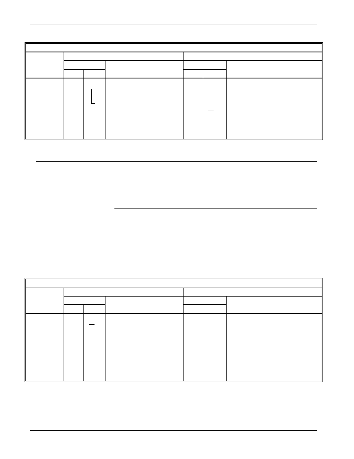
ROC800L Protocol Specifications Manual
Opcode 180
Communi-
Host Request to ROC800L
ROC800L Response to Host
cation
Data
Data
Opcode
Offset
Length
Description of Data
Offset
Length
Description of Data
Opcode 180:
6 1 Number of parameters
requested
6 1 Number of parameters requested
7
1
Point type
7
1
Point type
1
Point/Logic number
1
Point/Logic number
1
Parameter number
1
Parameter number
. (above repeated as
necessary)
x
Data comprising the parameter
.
(above repeated as necessary)
Version
Description
1.00
Introduced
Errors
The opcode responds with an error response if:
Opcode 181
Communi-
Host Request to ROC800L
ROC800L Response to Host
cation
Data
Data
Opcode
Offset
Length
Description of Data
Offset
Length
Description of Data
Opcode 181:
6 1 Number of parameters
requested
No data bytes.
7
1
Point type
Acknowledgment sent back.
1
Point/Logic number
1
Parameter number
x
Data comprising the
parameter
.
(above repeated as
necessary)
Table 2–23. Opcode 180, Request Parameters
Send
Specified
Parameters
2.24 Opcode 181, Write Parameters
Opcode 180 writes several parameters with a single request. The
parameters can be from different points and of different point types. The
opcode is intended to write any combination of parameters listed in this
document.
Set Specified
Parameters
The response is longer than 240 bytes.
The request is for an invalid parameter.
A parameter’s data is out of range.
A parameter is read-only.
Table 2–24. Opcode 181, Write Parameters
2-34 Opcodes Revised April 2020
Page 45

2.25 Opcode 203, General File Transfer
Version
Description
1.00
Introduced (Commands 1 – 5)
Paths
Opcode 255 Error
Codes
Invalid file FILE_DOES_NOT_EXIST 67
Opcode 203 transfers files to and from the flash file system.
/flash/userData (recommended for user C applications)
Flash file system full FLASH_FILE_SYSTEM_FULL 69
Invalid path INVALID_PATH 72
Invalid offset INVALID_OFFSET 73
Invalid option INVALID_OPTION 74
More than 10 files open TOO_MANY_FILES_OPEN 75
Other Limitations/
Special Cases
Maximum of 10 open files.
Can create only one directory per open command. That is, if
/flash/etc does not exist, you cannot open a file in /flash/etc/bin
You would be able to open a file in /flash/etc, which would create
the etc directory.
You can delete both directories and files with the delete command.
ROC800L Protocol Specifications Manual
Revised April 2020 Opcodes 2-35
Page 46

ROC800L Protocol Specifications Manual
Opcode 203
Host Request to ROC800L
ROC800L Response to Host
Data
Data
Command
Offset
Length
Description of Data
Offset
Length
Description of Data
Open
6 1 Command (1)
6 1 Command (1)
7 1 Options
writing
7 4 File Descriptor
8
100
Path
108
25
File Name (25 byte
character)
Read
6 1 Command (2)
6 1 Command (2)
7 4 File Descriptor
7 4 File Descriptor
11
4
Offset
11
4
File Size
15
4
Offset
19
1
Number of bytes
20
Numbytes
Data (maximum 230
(above repeated as
necessary)
Write
6 1 Command (3)
6 1 Command (3)
7
4
File Descriptor
7
4
File Descriptor
11
4
File Size
11
4
Offset
15
4
Offset
19
1
Number of bytes
20
Numbytes
Data (maximum 230
(above repeated as
necessary)
Close
descriptor)
6 1 Command (4)
6 1 Command (4)
7 4 File Descriptor
Delete
“/flash” 6 1
Command (5)
6 1 Command (5)
7
100
Path
107
25
File Name
Table 2–25. Opcode 203, General File Transfer
(An open must be
performed first
before reading or
writing to any file)
When creating a
new file the path
must start with
/flash/.
0 = Open file for reading
1 = Open file for writing
2 = Create new file for
writing (if doesn’t exist)
3 = Open file for update
(reading and writing)
4 = Truncate to zero
length or create file for
filename must include null
(Must use File
Descriptor returned
by the open
command)
(Must use File
Descriptor returned
by the open
command)
(Closes opened file
and removes
ber of
bytes)
ber of
bytes)
(Does not require
file descriptor) Can
delete file or
directory within
2-36 Opcodes Revised April 2020
Page 47

Opcode 203
Host Request to ROC800L
ROC800L Response to Host
Data
Data
Command
Offset
Length
Description of Data
Offset
Length
Description of Data
Read Directory
Contents
subdirectories
6 1 Command (6)
6 1 Command (5)
7 100
Path 7 1
Additional filenames to
1 = Yes
107
2 8 1 Total number of
filenames sent
9
Num-
Filenames (each file or
null character)
Version
Description
1.00
Introduced
Returns all
filenames in the
“./flash/data”
directory including
ROC800L Protocol Specifications Manual
read:
0 = No
2.26 Opcode 204, Long Request Event Data
Opcode 204 requests event data from the Event Log or Weights and
Measures log in the ROC800L. The Event Log consists of a maximum
of 450 events and the Weights and Measures Log consists of a
maximum of 1000 events. Each event consists of 92 bytes, organized
according to one of the five formats described below.
ber of
bytes
directory name is
separated with a null
character and the entire
data section ends with a
Revised April 2020 Opcodes 2-37
Page 48

ROC800L Protocol Specifications Manual
Opcode 204
Communi-
Host Request to ROC
ROC Response to Host
cation
Data
Data Opcode
Offset
Length
Description of Data
Offset
Length
Description of Data
Opcode 119:
6 1 Log type, 0 = standard events, 1 =
6 1 Number of events
7 1 # of events requested (max 10) *SEE
7 2 Starting Event Log
8 2 Starting Event Log index
9 2 Current Event Log
11
92
Event Data
.
(above repeated as
Description:
Type
Time
Event Specific Data
Byte:
0 1 2 3 4
5 - 91
Event
Description:
Type
Time
Operator ID
TLP
Data Type
New Value
Old Value
Table 2–26. Opcode 204, Long Request Event Data
Send
Specified
Number of
Events
Starting
with the
Specified
Event
Index
Event Data
Event Type
Parameter Change
weights and measures events
NOTE BELOW
being sent
index
index
necessary)
Note: If no events are requested, then no event data returns.
The event log stores the last 450 event entries. The Weights & Measures
log stores the last 1000 events. Each event consists of 92 bytes and has
the following general format:
The event type identifies what type of event is stored in the eventspecific data.
0 - No Event
1 - Parameter Change Event
2 - System Event
3 - FST Event
4 - User Event
5 - Power Lost Event
6 - Clock Set Event
7 - Calibrate Verify Event
A Parameter Change Event is logged any time a user makes a change to
any TLP. The data for the event has the following format:
2-38 Opcodes Revised April 2020
Byte: 0 1 5 6 7 8 9 10 11 12 - 51 52 - 91
Operator ID: Identifies who made the change.
TLP: Identifies what parameter was changed.
Page 49

ROC800L Protocol Specifications Manual
Event
Description
Code
Description
Spare
Data Type: Identifies the type of data stored in the new value and
old value fields.
0 - BIN
1 - INT8
2 - INT16
3 - INT32
4 - UINT8
5 - UINT16
6 - UINT32
7 - FL
8 - TLP
9 - AC (3 bytes)
10 - AC (7 bytes)
11 - AC (10 bytes)
12 - AC (12 bytes)
13 - AC (20 bytes)
14 - AC (30 bytes)
15 - AC (40 bytes)
16 – DOUBLE
17 - TIME
New Value: New value of the changed parameter.
System
Old Value: Old value of the changed parameter. The old value
always starts at byte offset 52.
A system event is an event logged internally by the ROC. The data for
the event has the following format:
Byte: 5 6-21 22-91
Code: More specifically defines the type of event that occurred.
144 - Initialization Sequence
145 - All Power Removed
146 - Initialize from defaults .
147 - ROM CRC Error
148 - Database Initialization
150 - Program Flash
151 - Reserved for ROC 800 only
152 - Reserved for ROC 800 only
153 - Reserved for ROC 800 only
154 - Smart Module Inserted
155 - Smart Module Removed
200 - Clock Set
248 - Text Message
249 - Download Configuration
250 - Upload Configurati on
251 - Calibration Timeout
252 - Calibration Cancel
253 - Calibration Success
254 - MVS Reset to Factory Defaults
Description: Textual description of the alarm.
Revised April 2020 Opcodes 2-39
Page 50

ROC800L Protocol Specifications Manual
Description
FST
Value
Description
Spare
Byte:
5 6 7 8 9
10
11
12
13
14
15
16
17
18
19
20 - 91
User Event
An event caused by the action of a logged in user. The data for the event
Description
Operator
Code
Description
Spare
Byte:
5 6 7 8 9
10
11
12
13
14
15
16
17
18
19
20
21
22 -
FST Event
:
An event logged by an FST. The data for the event has the following
format:
#
FST #: Identifies which FST logged the Event.
Value: Floating point value associated with event.
Description: Textual description of the event.
has the following format:
Operator ID: Identifies who made the change.
Code: More specifically defines the type of event that occurred.
Power Lost Event
144 - Initialization Sequence
145 - All Power Removed
146 - Initialize from defaults .
147 - ROM CRC Error
148 - Database Initialization
150 - Program Flash
151 - Reserved for ROC 800 only
152 - Reserved for ROC 800 only
153 - Reserved for ROC 800 only
154 - Smart Module Inserted
155 - Smart Module Removed
200 - Clock Set
248 - Text Message
249 - Download Configuration
250 - Upload Configurati on
251 - Calibration Timeout
252 - Calibration Cancel
253 - Calibration Success
254 - MVS Reset to Factory Defaults
Description: Textual description of the alarm.
An event logged when power to the ROC800-Series has been lost. The
data for the event has the following format:
Description: Time Not Used Spare
Byte: 5 6 7 8 9 10 11 12 13 14 15 16 17 18 19 20 21
2-40 Opcodes Revised April 2020
22 91
Page 51

ROC800L Protocol Specifications Manual
Clock Set Event
Event that is logged when the time is set on the ROC800-Series. The
Description:
Time
Not Used
Spare
Event
Version
Description
1.30
Introduced (Commands 1 & 2)
Time: Time that power to the unit was lost.
data for the event has the following format:
Byte: 5 6 7 8 9 10 11 12 13 14 15 16 17 18 19 20 21
Time: What the time on the ROC800-Series was set to.
Calibrate Verify
A Calibrate Verify Event is logged any time a user tests the calibration
of an I/O point.
Description:
Byte: 5 6 7 8 9 10 11 12 13 14
Operator
ID
TLP Raw Value Calibrated Value Spare
1
16 17 18 19 - 91
5
Operator ID: Identifies who tested the calibration.
TLP: Identifies what parameter was tested.
Raw Value: Value of input before calibration was applied. Data
type is float.
Calibrated Value: Value of input after calibration was applied.
Data type is float.
22 91
Timestamp
The timestamp for the alarm represents the time the alarm was logged.
The timestamp is a TIME [UINT32] which represents the number of
seconds that have elapsed since 12:00 a.m. Jan. 1, 1970.
2.27 Opcode 206, Read Transaction History Data
Opcode 206 requests a list of transaction numbers and the date those
numbers were created from a transactional history segment (command
1) and retrieves data from a particular transaction (command 2).
Revised April 2020 Opcodes 2-41
Page 52

ROC800L Protocol Specifications Manual
Opcode 206
Host Request to ROC800L
ROC800L Response to Host
Data
Data
Command
Offset
Length
Description of Data
Offset
Length
Description of Data
List Transactions
6 1 Command (1)
6 1 Command (1)
7 1 Segment
7 1 Number of transactions
in message
8 2 Transaction offset (starts
oldest transaction);
8 1 More transactions than
9 10
Description
Command (1)
19
2
Payload Size (size of
Command 2.
21
2
Transaction Number
23
4
Date created
(Above 6 bytes repeated for num
Read Transaction
6 1 Command (2)
6 1 Command (2)
7 1 Segment
7 1 Message Data Size
byte)
8 2 Transaction Number
8 1 More data than included
(Yes)
10
2
Offset into data (this is a
type value pairs)
9 1 Data Type1
10
Data
size
Value
(Above TLP, Data Type, Value repeated
U8 = 1
STRING10 = 11
S8 = 2
STRING12 = 12
U16 = 3
STRING20 = 13
U32 = 5
STRING30 = 14
S32 = 6
T_STRING40 = 15
FLOAT = 7
BINARY (1 byte) = 17
DOUBLE = 8
TLP (3 bytes) = 18
STRING3 = 9
TIME (4 bytes) = 20
STRING7 = 10
Table 2–27. Opcode 206, Read Transactional History Data
Gives a list of the
transactions
currently stored in
the system.
at first transaction stored
in the Segment, which is
index 0. After rollover, this
is not necessarily the
those returned in this
request. Valid values
are 0 (No) and 1 (Yes)
the data portion of this
segment’s transactions.
This is the size of all
data types and value
pairs returned in
Reads data for the
specified
transaction
1
Valid data types and the corresponding value returns:
transactions)
(size of data below this
in this response. Valid
values are 0 (No) and 1
byte index into the data
for num bytes)
2-42 Opcodes Revised April 2020
Page 53

2.28 Opcode 224, SRBX Signal
Version
Description
1.00
Introduced
Opcodes 224
Communi-
Host Request to ROC800L
ROC800L Response to Host
cation
Data
Data
Opcode
Offset
Length
Description of Data
Offset
Length
Description of Data
Opcode 224:
Exception
Host could possibly use a
No data bytes.
Version
Description
1.00
Introduced
Opcode 225
Communi-
Host Request to ROC800L
ROC800L Response to Host
cation
Data
Data
Opcode
Offset
Length
Description of Data
Offset
Length
Description of Data
Opcode 225:
6
2
Current Alarm Log index
No data bytes. Acknowledgment
received from the host.
Version
Description
1.00
Introduced
Opcode 224 represents the message that is sent to the host to signal an
SRBX. Refer to Chapter 6 for an example of spontaneous report-by-
exception.
Table 2–28. Opcode 224, SRBX Signal
ROC800L Protocol Specifications Manual
Signal
Report- by-
variety of different ways to
retrieve the alarm index.
2.29 Opcode 225, Acknowledge SRBX
Opcode 225 acknowledges receipt of an SRBX alarm message. Refer to
Chapter 6 for an example of spontaneous report-by-exception.
Table 2–29. Opcode 225, Acknowledge SRBX
Acknowledge
Report-byException
sent back.
ROC800L clears SRBX status if the
ROC800L’s alarm index equals data
2.30 Opcode 255, Error Indi c ator
Revised April 2020 Opcodes 2-43
Opcode 255 is an error message indicator. If an opcode request is
invalid, a request contains invalid data, or a value parmeter is out of
range, the response is Opcode 255.
This special opcode’s data consists of an error code byte and an offset
byte, as shown below:
Page 54

ROC800L Protocol Specifications Manual
Error Code
Description
Byte that caused error
1
Invalid Opcode request.
Opcode
2
Invalid parameter number.
Parameter number
3
Invalid logical number.
Logical number
4
Invalid point type.
Point type
5
Received too many data bytes.
Length
6
Received too few data bytes.
Length
12
Obsolete (Reserved, but not used)
13
Outside valid address range.
Address
14
Invalid history request.
History point number
16
Invalid event entry.
Event code
17
Requested too many alarms.
Number of alarms requested
18
Requested too many events.
Number of events requested
19
Write to read only parameter.
these may be RO, and some may not.
Parameter number
20
Security error.
Opcode
21
Invalid security logon.
Login ID or Password
22
Invalid store and forward path.
Any address or group
24
History configuration in progress.
Opcode
25
Invalid parameter range
Parameter
29
Invalid 1 day history index request.
History Segment, point, day or month
30
Invalid history point.
History Point
31
Invalid Min/Max request.
History segment or point number
32
Invalid TLP.
Point type, parameter, or logical number
33
Invalid time.
Seconds, minutes, hours, days, months, or years
34
Illegal Modbus range
Point/Logical number
63
Requested Access Level Too High
Access Level
77
Invalid logoff string
Ignored
Exception for Opcode 166 which can
have multiple parameters. Some of
2-44 Opcodes Revised April 2020
The offset is the byte offset into the message in which an error was
detected. Multiple parameters may cause an error, so there may be
multiple error codes in the Opcode 255 response. This enables the
separation of good data from bad. A multiple set could have some errors
returned as well as some data being set. Table 2-34, Valid Error Codes
for a Given Opcode, contains all of the error codes and the opcodes that
may cause them.
Page 55

Opcode 255
Communi-
Host Request to ROC800L
ROC800L Response to Host
Cation
Data
Data
Opcode
Offset
Length
Description of Data
Offset
Length
Description of Data
Opcode 255:
Invalid
Reserved for ROC800L
use.
1
Error code (see Opcode 200)
1
Offset of the byte that caused the
error.
.
(above repeated as necessary).
Note below:
Parameters
in Request
Received by
ROC800L
ROC800L Protocol Specifications Manual
Table 2–30. Opcode 255, Request Multiple History Point Data
6
7
With the exceptions shown in the
Note: The following are special cases for the value returned in offset 7:
For Opcodes 166 and 167:
Returns the requested point type’s Actual parameter. For
example, if you request parameters 5 through 10 and 6 fails,
the value of parameter 6 (not 2) is returned in offset 7.
For Opcodes 180 and 181:
Returns the TLP-Tuple offset. For example, if you request
ten TLPs and the 9th TLP has an error, 9 values are returned.
Revised April 2020 Opcodes 2-45
Page 56

ROC800L Liquids Protocol Specifications Manual
Request current ROC800L
Set operator id code
Request I/O Point Position
Request today and yesterday min
and max values
index
Request event data
Request single point parameters
RBX Ack from host
Error indicator
Description
# 6 7 8 10
11
17
24
50
105
108
118
119
135
136
137
166
167
180
181
224
225
255
Error Codes
Invalid opcode request
1
NA
NA
NA
NA
NA
NA
NA
NA
NA
NA
NA
NA
NA
NA
NA
NA
NA
NA
NA
NA
NA
NA
Invalid parameter number
2 NA NA
Invalid logical number
3 x x x x NA NA
Invalid point type
4 NA NA
Received too many data bytes
5 x x x x x x x x x x x x x x X x x x x NA NA
Received too few data bytes
6 x x x x x x x x x X x X x x x x NA x NA
Outside valid address range
13 NA NA
Invalid history request
14 x x NA NA
Invalid FST request
15 NA NA
Invalid event entry
16 NA NA
Requested too many alarms
17 X NA NA
Requested too many events
18 X NA NA
Write to read only parameter
19 x* x NA NA
Security error
20 x NA NA
Invalid security logon
21 x NA NA
Invalid store and forward path
22 x NA NA
Flash programming error
23 NA NA
History configuration in progress
24 x x x x x NA NA
Invalid parameter range
25 x x x x NA NA
Table 2–31. Valid Error Code for a Given Opcode
Read data and time
Set real time clock
This chart shows the ROC
Plus Protocol relationship
between opcodes and the
point types that they
reference.
Read configurable opcode point
Write configurable opcode point
Set store and forward action
Request history tag and periodic
Request alarm data
Request history point data
Request history index data
Request history index for a day
Set single point parameters
Request parameters
Write parameters
RBX send to host
2-46 Opcodes Revised April 2020
Page 57

This chart shows the ROC
Request current ROC800L
Set operator id code
Request I/O Point Position
Request today and yesterday min
and max values
index
Request event data
Request single point parameters
RBX Ack from host
Error indicator
Description
# 6 7 8 10
11
17
24
50
105
108
118
119
135
136
137
166
167
180
181
224
225
255
Invalid User C++ program number
26 NA NA No room for User C++ program
27 NA NA
Out of sequence User C++ packet
28 NA NA
Invalid 1 day history index request
29 x NA NA
Invalid history point
30 x NA NA
Invalid Min/Max request
31 x NA NA
Invalid TLP
32 x x x x NA NA
Invalid time.
33 x NA NA
Illegal Modbus range
34 x x NA NA
Plus Protocol relationship
between opcodes and the
point types that they
reference.
number
ROC800L Liquids Protocol Specifications Manual
Read data and time
Set real time clock
Read configurable opcode point
Write configurable opcode point
Set store and forward action
Request history tag and periodic
Request alarm data
Request history point data
Request history index data
Request history index for a day
Set single point parameters
Request parameters
Write parameters
RBX send to host
* = Exception, for opcode 166 which can have multiple parameters. Some of these may be RO or Invalid State, and some may not.
Revised April 2020 Opcodes 2-47
Page 58

ROC800L Liquids Protocol Specifications Manual
[This page is intentionally left blank.]
2-48 Opcodes Revised April 2020
Page 59

Chapter 3 – Paramet er Lists for Point Types
Configuring the ROC800L requires you to be familiar with the structure of the database. The database is broken
into individual parameters and each database parameter is uniquely associated by parameter number and point
type.
This section details ROC point types, Data Types, and User Defined Point (UDP) Types.
3.1 Type, Location/Logical, and Parameter (TLPs)
You reference data in the ROC800L by type, location or logical, and parameter (TLP). Type refers to the number
of the point type. The location or logical number is a value based on physical input or output. A parameter is a
numeric value assigned to each piece of data contained in a given point type. The tables in this section list the
parameters numbers and descriptions for each of the point types.
3.2 Logical/Location Details
Within a point type, you reference individual points by either a location or a logical number (the “L” in the TLP
referencing scheme). The ROC Plus protocol uses location (which is based on a physical input or output [I/O]
“module and point” location) for point types 101 through 109. All other point types use a logical number and are
simply numbered in sequence.
ROC800L Protocol Specifications Manual
Location (Physical Point Numbers 1 – 160): For point types 101 through 109, use the following location
numbers for the field I/O and for diagnostic inputs:
• Location Numbers 0 to 15 are assigned to the system I/O. For example, the five diagnostic points in a
ROC800L would be 0 through 4.
• Location Numbers 16 to 160 are assigned to field I/O. For example, an I/O module in slot 1 with 4 I/O
points would be assigned as points 16 through 19.
Logical (Point Numbers 0 – 127): For all other point types (other than 101 through 109), the logical number
is 0 to x, where x is one less than the total number of points that exist for that point type. For example, the 16
PIDs would be logical numbers 0 through 15.
Table 3-1 details data types.
Revised April 2020 Parameter Lists for Point Types 3-1
Page 60

ROC800L Protocol Specifications Manual
Data Type
Definition
# of Bytes
Default Range
BIN
Binary
1
01 For each Bit
AC
ASCII character groups
1 per character
0x20 0x7E for each character
INT8
Signed Integer – 8 bits 1 -128127
INT16
Signed Integer – 16 bits 2 -32,76832,767
INT32
Signed Integer – 32 bits
4
-2,147,483,6482,147,483,647
UINT8
Unsigned Integer – 8 bits 1 0255
UINT16
Unsigned Integer – 16 bits 2 065,535
UINT32
Unsigned Integer – 32 bits
4
04,294,967,295
FL
Single Precision Floating Point – IEEE
Format
4
Any valid IEEE double precision float (see Chapter 5)
DBL
Double Precision Floating Poi nt – IEEE
Format
8
Any valid IEEE double precision float (see Chapter 5)
TLP
Type, Point or Logical Number, Parameter
Number
3
{0255, 0255, 0255}
TIME
Arithmetic Time: Number of seconds since
4
004,294,967,296
Jan 1, 1970 00:00:00 Feb. 7, 2106 06:28:15
Jan 1 1970 @ 00:00:00. This is a UINT32.
Table 3–1. Data Type
3.3 Binary Field (BIN) Example
This section provides an example alarm code from an analog input point type to demonstrate how a binary
parameter is returned. A 1 in any bit indicates that bit is active or enabled.
3-2 Parameter Lists for Point Types Revised April 2020
Scanning Disabled Alarm
Point Fail Alarm
Not Used
Bit 7 6 5 4 3 2 1 0
Response Code 1 0 0 0 0 0 0 0
High High Alarm
Rate Alarm
Low Low Alarm
High Alarm
Low Alarm
Page 61

3.4 Point Type Table Fields
Name
Provides the name of the parameter.
R/W
R/W_Log
System or User Update
Length
Indicates the number of bytes the parameter uses.
Range
Default
Description
Provides a brief description of the parameter.
Each point type table is prefaced by a short description, a statement of the number of logical points (or
iterations) of the point type, and the storage location for point type information. Point type tables contain the
following information:
Field Description
Param# Defines the specific parameter number associated with that point type.
ROC800L Protocol Specifications Manual
Access
Data Type Identifies the type of data being stored. Data types are defined in Chapter 2.
Identifies the range of accepted values for the parameter.
Indicates the initial value of the parameter.
Ver Identifies the version of program in which the parameter was first introduced.
Indicates if the parameter can be read from and written to (
is read-only (R/O). Although Weights and Measures (W&M) parameters may always
be read-from, they may only be written-to on a conditional basis. When they are
written-to they are logged to the Weights and Measures log. This is Read-Write
Conditional (R/W_CNDL). Finally, there are parameters that can always be writtento and read-from but are logged to the Weights and Masures log. These are a
Read-Write-Log (
Identifies who has write access to the data.
)
) or if the parameter
Revised April 2020 Parameter Lists for Point Types 3-3
Page 62

ROC800L Protocol Specifications Manual
Description:
Point type 82 provides the Virtual Discrete Outputs parameters for setting up discrete outputs.
Number of Logical Points:
Storage Location:
Point Type 82, Virtual Discrete Outputs
3.4.1 Point Type 82: Virtual Discrete Outputs
24 logical points for Virtual Discrete Outputs may exist.
Point type 82 is saved to internal configuration memory.
Table 3-2: Point Type 82, Virtual Discrete Outputs
Param # Name Access
0 Point Tag ID R/W User AC 10
1 Units Tag R/W User AC 10
2 Scanning Mode R/W User UINT8 1
3 Alarming R/W User UINT8 1
4 SRBX on Clear R/W User UINT8 1
5 SRBX on Set R/W User UINT8 1
6 Alarm Code R/O System BIN 1
6.0 Not Used Bit 0 0 Not Used
6.1 Not Used Bit 1 0 Not Used
6.2 Not Used Bit 2 0 Not Used
6.3 Not Used Bit 3 0 Not Used
6.4 Not Used Bit 4 0 Not Used
6.5 Scanning Manual Alarm Bit 5 0 1.00
6.6 Not Used Bit 6 0 Not Used
System or
User Update
Data Type Length Range Default Ver
0x20 → 0x7E for each
0x20 → 0x7E for each
“DO
ASCII character
ASCII character
0 → 2
0 → 1
0 → 1
0 → 1
0x00 → 0xFF
Default”
“Percent “ 1.00
1 1.00 Indicates the scanning mode. Valid values are:
0 1.00
0 1.00
0 1.00
0x00 1.00
1.00
Description of functionality and meaning of
values
Identification name for specific DO. Values must
be printable ASCII characters.
Describes the units used by the DO. Values must
be printable ASCII characters.
0 = Disabled (no changes to output occur)
1 = Automatic (anything changes DO values)
2 = Manual (only user can change DO values)
If enabled, alarms may be generated and sent to
the Alarm Log. Valid values are 0 (Disabled) and
1 (Enabled).
Indicates a SRBX alarm is desired if an alarm
condition clears. Valid values are 0 (SRBX on
Clear Disabled) and 1 (SRBX on Clear Enabled).
Indicates a SRBX alarm is desired if an alarm
condition occurs. Valid values are 0 (SRBX on
Set Disabled) and 1 (SRBX on Set Enabled).
If set, the Scanning (parameter #2) has been set
to Manual. If clear, the Scanning (parameter #2)
has been set to either Disable or Automatic
3-4 Parameter Lists for Point Types Revised April 2020
Page 63

ROC800L Protocol Specifications Manual
Point Type 82, Virtual Discrete Outputs
Param # Name Access
6.7 Scanni ng Disabl ed Alarm Bit 7 0 1.00
7 Failsafe on Reset R/W User UINT8 1
8 Auto Output R/W Both UINT8 1
9 Accumulated Value R/W Both UINT32 4
10 Momentary Mode R/W User UINT8 1
11 Momentary Active R/O System UINT8 1
12 Toggle Mode R/W User UINT8 1
13
14 Time On R/W Both FL 4
Timed Discrete Output (TDO)
Mode
R/W User UINT8 1
System or
User Update
Data Type Length Range Default Ver
0 → 4,294,967,295
DO: 0.002 → 43,200.0
DOR: 0.05→ 43,200.0
0 → 1
0 → 1
0 → 1
0 → 1
0 → 1
0 → 1
0 1.00
0 1.00
0 1.00
0 1.00
0 1.00
0 1.00
0 1.00
1.0 1.00
Description of functionality and meaning of
values
If set, the Scanning (parameter #2) has been
disabled. If clear, the Scanning (parameter #2)
has been set to either Automatic or Manual.
If enabled, the Status (parameter #8) is set to the
status indicated in ‘Failsafe Status Value’
(Parameter #22) on a restart of any kind. If
disabled, the last Status before the restart will be
used. Valid values are 0 (Output Last Status on
Reset) and 1 (Use Failsafe value on Reset).
Controls the state of the DO when Scanning
(parameter #2) is in auto mode. In other words,
the physical output gets this status when the
mode (parameter # 2) is set to Automatic.
Number of times the Status (parameter #8) goes
from OFF to ON.
If enabled, the Status (parameter #8) is turned
ON for the entered Time On (parameter #14) and
then be turned OFF. Valid valules are 0
(Momentary Disabled) and 1 (Momentary
Enabled).
Indicates that the DO currently has the
Momentary ability active. Valid values are 0
(Momentary Not Active) and 1 (Momentary
Active).
If enabled, the Status (parameter #8) is ON for
the entered Time On (parameter #14) and then
turned OFF for the same Time On. The Status
continues to cycle between the ON and OFF
states. Vallid values are 0 (Toggle Disabled) and
1 (Toggle Enabled).
If enabled, the Status (parameter #8) is turned
ON for a calculated Time On (parameter #14)
based upon the entered EU Value (parameter
#20). After the Time On has expired, the Status is
turned OFF and remains that way until a new EU
Value is entered. Valid values are 0 (TDO
Disabled) and 1 (TDO Enabled).
Number of seconds the Status (parameter #8) is
turned on for if in TDO, Toggle, or Momentary
Mode.
Revised April 2020 Parameter Lists for Point Types 3-5
Page 64

ROC800L Protocol Specifications Manual
Point Type 82, Virtual Discrete Outputs
Param # Name Access
15 Cycle Time R/W User FL 4
16 Low Reading Time R/W User FL 4
17 High Reading Time R/W User FL 4
18 Low Reading EU R/W User FL 4 Any valid IEEE 754 float 0.0 1.00 Minimum EU Value (parameter #20) possible.
19 High Reading EU R/W User FL 4 Any valid IEEE 754 float 100.0 1.00 Maximum EU Value (parameter #20) possible.
20 EU Value R/W Both FL 4 Any valid IEEE 754 float 0.0 1.00 Value in Engineering Units.
21 Manual Output R/W Both UINT8 1
22 Failsafe Output R/W User UINT8 1
23
24 Physical Output R/O System UINT8 1
25 Invert Output Mode R/W User UINT8 1
26 DO Type R/O System UINT8 1
RESERVED
System or
User Update
Data Type Length Range Default Ver
>0.0 → 43,200.0
0.0 → 43,200.0
0.0 → 43,200.0
0 → 1
0 → 1
0 → 1
0 → 1
0 → 1
15.0 1.00
3.0 1.00
12.0 1.00
0 1.00
1 1.00
0 1.00
0 1.00
0 1.00
Description of functionality and meaning of
values
Number of seconds for when TDO Mode
(parameter #13) and Toggle Mode (parameter
#12) are selected. The Status (parameter #8) is
ON for the calculated Time On (parameter #14)
based upon the entered EU Value (parameter
#20). The Status is then turned OFF based upon
the Cycle Time minus the Time On.
Minimum number of seconds the calculated Time
On (parameter #14) is when the entered EU
Value (parameter #20) is less than or equal to the
entered Low Reading EU (parameter #18).
Maximum number of seconds the calculated Time
On (parameter #14) will be when the entered EU
Value (parameter #20) is greater than or equal to
the entered High Reading EU (parameter #19).
Controls the state of the DO when Scanning
(parameter #2) is in manual mode. In other
words, the physical output gets this status when
the mode (parameter # 2) is set to Automatic.
The state the output is placed in when the unit is
started and the Failsafe on Reset Parameter
(Parameter 7) is set to 1, Use Failsafe value on
reset.
I
Reserved for future use
Indicates the current state of the DO. Valid values
are 1 (ON) and 0 (OFF).
Inverts the output of the DO channel, allowing
you to use TDO mode to keep a channel OFF for
a set amount of time and then bring the channel
back ON. Valid values are 0 (Normal) and 1
(Inverted).
Note: This always inverts the output, including
the Failsafe Output.
Indicates the DO type. Valid values are 0 (DO
Relay) or 1 (DO Solid State).
3-6 Parameter Lists for Point Types Revised April 2020
Page 65

ROC800L Protocol Specifications Manual
Description:
Point type 84 provides additional parameters associated with the HART 2 module.
Number of Logical Points:
Storage Location:
Point Type 84, HART Extended
Note
persistent
Note
persistent
3.4.2 Point Type 84: HART Extended Point Type
4 logicals per installed module imay exist.
Any parameter noted as “persistent” is saved to internal configuration memory.
Table 3-3: Point Type 84, HART Extended Point Type
Param# Name Access
0 Channel Alarming R/W User UINT8 1 0-1 0 1.00
1 Channel Alarm Code R/O System BIN 1
1.0 AI Low Alarm Bit 0 0
1.2 AI High Alarm Bit 2 0
1.5 AO Readback Alarm B it 5 0
1.6 Point Fail Alarm Bit 6 0
2 AI Low Alarm EU R/W User FL 4
3 AI High Alarm EU R/W User FL 4
System or
User Update
Data Type Length Range Default Ver
0x00 → 0xFF
Any valid IEEE 754
float
Any valid IEEE 754
float
0 1.00 Alarm value for the HART channel.
-10.0 1.00 Alarm value for HART AI Low Alarm.
110.0 1.00 Alarm value for HART AI High Alarm.
Description of functionality and meaning
of values
If enabled, generates channel alarms and
sends them to the Alarm Log. Valid values
are 0 (Disabled) and 1 (Enabled).
Note: This parameter is persistent.
: This parameter is
If set, the HART AI EU value is less than or
equal to the AI Low Alarm EU (parameter
#2). If clear, the HART EU value is greater
than the AI Low Alarm EU (parameter #2).
Only applies when the channel is configured
as an AI.
If set, the HART AI EU value is greater than
or equal to the AI High Alarm EU (parameter
#3). If clear, the HART EU value is less than
the AI High Alarm EU (parameter #3). Only
applies when the channel is configured as
an AI.
If set, the HART module is not detecting a
device on the output line. If clear, the analog
output is functioning correctly. Only applies
when the channel is configured as an AO.
If set, communicating with the HART module
has failed. If clear, the HART’s hardware is
operating properly.
Note: This parameter is persistent.
: This parameter is
.
.
Revised April 2020 Parameter Lists for Point Types 3-7
Page 66

ROC800L Protocol Specifications Manual
Point Type 84, HART Extended
Note
persistent
Param# Name Access
4 Alarm Deadband R/W User FL 4
5 Device 1 Alarming R/W User UINT8 1 0-1 0 1.00
6 Device 1 Alarm Code R/O System BIN 1
6.0 Device 1 PV Low Alarm Bit 0 0
6.2 Device 1 PV High Alarm Bit 2 0
6.6 Device 1 Point Fail Alarm Bit 6 0
7 Device 1 PV Low Alarm Value R/W User FL 4
System or
User Update
Data Type Length Range Default Ver
Any valid IEEE 754
float
0x00 → 0xFF
Any valid IEEE 754
float
2.0 1.00
0 1.00
-10 1.00 Alarm value for Device PV Low Alarm.
Description of functionality and meaning
of values
Provides a range (±) that the HART AI EU
Value may move between without causing
another alarm.
Note: This parameter is persistent.
If enabled, generates device alarms and
sends them to the Alarm Log. Valid values
are 0 (Disabled) and 1 (Enabled).
Note: This parameter is persistent.
Alarm code for the device on the HART
channel.
Note: This parameter is persistent.
If set, the Device PV value is less than or
equal to the Device PV Low Alarm Value. If
clear, the Device PV value is greater than
the Device PV Low Alarm Value.
If set, the Device PV value is greater than or
equal to the Device PV High Alarm Value. If
clear, the Device PV value is less than the
Device PV High Alarm Value.
If set, communicating with the HART Device
has failed. If clear, the HART Device is
operating correctly.
Note: This parameter is persistent.
8
9 Device 1 Alarm Deadband R/W User FL 4
10 Device 1 Download PV R/W USER FL 4
11 Device 1 Live PV Value R/O System FL 4
Device 1 PV High Alarm
Value
3-8 Parameter Lists for Point Types Revised April 2020
R/W User FL 4
Any valid IEEE 754
float
Any valid IEEE 754
float
Any valid IEEE 754
float
Any valid IEEE 754
float
1,000,000 1.00 Alarm value for Device PV High Alarm.
0 1.00
0 1.00
0 1.00
: This parameter is
Provides a range (±) that the Device PV
Value may move between without causing
another alarm.
Note: This parameter is persistent.
When the device Poll Mode is set to
Download PV (4), the PV value of the device
is set to the Device Download PV value.
Note: This parameter is persistent.
The current value of the PV returned from
the card or last live value if scan mode is set
to Skip this Device or Slot modes.
Note: This parameter is persistent.
.
Page 67

ROC800L Protocol Specifications Manual
Point Type 84, HART Extended
Note
persistent
Note
persistent
Param# Name Access
12 Device 1 In Use Mode
13 Device 1 In Use Status R/O System UINT8 1 0-6 0 1.00
14 Device 2 Alarming R/W User UINT8 1 0-1 0 1.00
15 Device 2 Alarm Code R/O System BIN 1
15.0 Devic e 2 PV Low Alarm Bit 0 0
15.2 Devic e 2 PV High Alarm B it 2 0
15.6 Devic e 2 Point Fail Alarm Bit 6 0
16 Device 2 PV Low Alarm Value R/W User FL 4
17
18 Device 2 Alarm Deadband R/W User FL 4
Device 2 PV High Alarm
Value
R/W_
LOG
R/W User FL 4
System or
User Update
User UINT8 1 0-2 0 1.00
Data Type Length Range Default Ver
0x00 → 0xFF
Any valid IEEE 754
float
Any valid IEEE 754
float
Any valid IEEE 754
float
0 1.00
-10 1.00 Alarm value for Device PV Low Alarm.
1,000,000 1.00 Alarm value for Device PV High Alarm.
0 1.00
Description of functionality and meaning
of values
Determines what value is used to populate
the PV parameter. Valid values are:
0 = live or last live
1 = failsafe value
2 = download value. Overrides failsafe mode
except when in live mode.
Note: This parameter is persistent.
Status of what value is being used to
populate the PV. Valid values are:
0 = live or last live value without failure
1 = last live/scanning disabled
2 = failed to last live value
3 = failed to download value
4 = failed to failsafe value,
5 = set to download value, 6 = set to failsafe
value
Note: This parameter is persistent.
If enabled, device alarms may be generated
and sent to the Alarm Log. Valid values are
0 (Disabled) and 1 (Enabled).
Note: This parameter is persistent.
Alarm code for the device on the HART
channel.
Note: This parameter is persistent.
If set, the Device PV value is less than or
equal to the Device PV Low Alarm Value. If
clear, the Device PV value is greater than
the Device PV Low Alarm Value.
If set, the Device PV value is greater than or
equal to the Device PV High Alarm Value. If
clear, the Device PV value is less than the
Device PV High Alarm Value.
If set, communicating with the HART Device
has failed. If clear, the HART Device is
operating correctly.
: This parameter is
: This parameter is
Provides a range (±) within which the Device
PV Value may move between without
causing another alarm.
Note: This parameter is persistent.
.
.
Revised April 2020 Parameter Lists for Point Types 3-9
Page 68

ROC800L Protocol Specifications Manual
Point Type 84, HART Extended
Note
persistent
Note
persistent
Note
persistent
Param# Name Access
19 Device 2 Download PV R/W USER FL 4
20 Device 2 Live PV Value R/O System FL 4
21 Device 2 In Use Mode
22 Device 2 In Use Status R/O System UINT8 1 0-6 0 1.00
23 Device 3 Alarming R/W User UINT8 1 0-1 0 1.00
24 Device 3 Alarm Code R/O System BIN 1
24.0 Devic e 3 PV Low Alarm Bit 0 0
24.2 Devic e 3 PV High Alarm B it 2 0
24.6 Devic e 3 Point Fail Alarm Bit 6 0
R/W_
LOG
System or
User Update
User UINT8 1 0-2 0 1.00
Data Type Length Range Default Ver
Any valid IEEE 754
float
Any valid IEEE 754
float
0x00 → 0xFF
0 1.00
0 1.00
0 1.00
Description of functionality and meaning
of values
When the device Poll Mode is set to
Download PV (4), the PV value of the device
is set to the Device Download PV value.
: This parameter is
The current value of the PV returned from
the card or last live value if scan mode is set
to Skip this Device or Slot modes.
: This parameter is
Determines what value populates the PV
parameter. Valid values are:
0 = live or last live
1 = failsafe value
2 = download value. Overrides failsafe mode
except when in live mode.
Note: This parameter is persistent.
Status of what value is being used to
populate the PV. Valid values are:
0 = live or last live value without failure
1 = last live/scanning disabled
2 = failed to last live value
3 = failed to download value,
4 = failed to failsafe value
5 = set to download value
6 = set to failsafe value
Note: This parameter is persistent.
If enabled, device alarms may be generated
and sent to the Alarm Log. Valid values are
0 (Disabled) and 1 (Enabled). .
: This parameter is
Alarm code for the device on the HART
channel.
Note: This parameter is persistent.
If set, the Device PV value is less than or
equal to the Device PV Low Alarm Value. If
clear, the Device PV value is greater than
the Device PV Low Alarm Value.
If set, the Device PV value is greater than or
equal to the Device PV High Alarm Value. If
clear, the Device PV value is less than the
Device PV High Alarm Value.
If set, communicating with the HART Device
has failed. If clear, the HART Device is
operating correctly.
.
.
.
3-10 Parameter Lists for Point Types Revised April 2020
Page 69

ROC800L Protocol Specifications Manual
Point Type 84, HART Extended
Note
persistent
Note
persistent
Param# Name Access
25 Device 3 PV Low Alarm Value R/W User FL 4
26
27 Device 3 Alarm Deadband R/W User FL 4
28 Device 3 Download PV R/W USER FL 4
29 Device 3 Live PV Value R/O System FL 4
30 Device 3 In Use Mode
31 Device 3 In Use Status R/O System UINT8 1 0-6 0 1.00
32 Device 4 Alarming R/W User UINT8 1 0-1 0 1.00
33 Device 4 Alarm Code R/O System BIN 1
Device 3 PV High Alarm
Value
R/W User FL 4
R/W_
LOG
System or
User Update
User UINT8 1 0-2 0 1.00
Data Type Length Range Default Ver
Any valid IEEE 754
float
Any valid IEEE 754
float
Any valid IEEE 754
float
Any valid IEEE 754
float
Any valid IEEE 754
float
0x00 → 0xFF
-10 1.00 Alarm value for Device PV Low Alarm.
1,000,000 1.00 Alarm value for Device PV High Alarm.
0 1.00
0 1.00
0 1.00
0 1.00
Description of functionality and meaning
of values
Note: This parameter is persistent.
: This parameter is
Provides a range (±) that the Device PV
Value may move between without causing
another alarm.
Note: This parameter is persistent.
When the device Poll mode is set to
Download PV (4), the PV value of the device
is set to the Device Download PV value.
Note: This parameter is persistent.
The current value of the PV returned from
the card or last live value if Scan mode is set
to Skip this Device or Slot modes.
: This parameter is
Determines what value populates the PV
parameter. Valid values are:
0 = live or last live
1 = failsafe value
2 = download value. Overrides failsafe mode
except when in live mode.
Note: This parameter is persistent.
Status of what value is being used to
populate the PV. Valid values are:
0 = live or last live value without failure
1 = last live/scanning disabled
2 = failed to last live value
3 = failed to download value
4 = failed to failsafe value
5 = set to download value
6 = set to failsafe value
Note: This parameter is persistent.
If enabled, device alarms may be generated
and sent to the Alarm Log.
0 = Disabled, 1 = Enabled.
Note: This parameter is persistent.
Alarm code for the device on the HART
channel.
Note: This parameter is persistent.
.
.
Revised April 2020 Parameter Lists for Point Types 3-11
Page 70

ROC800L Protocol Specifications Manual
Point Type 84, HART Extended
Note
persistent
Param# Name Access
33.0 Devic e 4 PV Low Alarm Bit 0 0
33.2 Devic e 4 PV High Alarm B it 2 0
33.6 Devic e 4 Point Fail Alarm Bit 6 0
34 Device 4 PV Low Alarm Value R/W User FL 4
35
36 Device 4 Alarm Deadband R/W User FL 4
37 Device 4 Download PV R/W USER FL 4
38 Device 4 Live PV Value R/O System FL 4
39 Device 4 In Use Mode
Device 4 PV High Alarm
Value
R/W User FL 4
R/W_
LOG
System or
User Update
User UINT8 1 0-2 0 1.00
Data Type Length Range Default Ver
Any valid IEEE 754
float
Any valid IEEE 754
float
Any valid IEEE 754
float
Any valid IEEE 754
float
Any valid IEEE 754
float
-10 1.00 Alarm value for Device PV Low Alarm.
1,000,000 1.00 Alarm value for Device PV High Alarm.
0 1.00
0 1.00
0 1.00
Description of functionality and meaning
of values
If set, the Device PV value is less than or
equal to the Device PV Low Alarm Value. If
clear, the Device PV value is greater than
the Device PV Low Alarm Value.
If set, the Device PV value is greater than or
equal to the Device PV High Alarm Value. If
clear, the Device PV value is less than the
Device PV High Alarm Value.
If set, communicating with the HART Device
has failed. If clear, the HART Device is
operating correctly.
Note: This parameter is persistent.
: This parameter is
Provides a range (±) that the Device PV
Value may move between without causing
another alarm.
Note: This parameter is persistent.
When the device Poll Mode is set to
Download PV (4), the PV value of the device
is set to the Device Download PV value.
Note: This parameter is persistent.
The current value of the PV returned from
the card or last live value if scan mode is set
to Skip this Device or Slot modes.
Note: This parameter is persistent.
Determines what value populates the PV
parameter. Valid values are::
0 = live or last live
1 = failsafe value
2 = download value. Overrides failsafe mode
except when in live mode.
Note: This parameter is persistent.
.
3-12 Parameter Lists for Point Types Revised April 2020
Page 71

ROC800L Protocol Specifications Manual
Point Type 84, HART Extended
Note
persistent
Note
persistent
Note
persistent
Note
persistent
Param# Name Access
40 Device 4 In Use Status R/O System UINT8 1 0-6 0 1.00
41 Device 5 Alarming R/W User UINT8 1 0-1 0 1.00
42 Device 5 Alarm Code R/O System BIN 1
42.0 Devic e 5 PV Low Alarm
42.2 Devic e 5 PV High Alarm
42.6 Devic e 5 Point Fail Alarm
43 Device 5 PV Low Alarm Value
44
45 Device 5 Alarm Deadband
46 Device 5 Download PV
47 Device 5 Live PV Value
Device 5 PV High Alarm
Value
R/W
R/W
R/W
R/W
R/O
System or
User Update
Bit 0 0
Bit 2 0
Bit 6 0
User FL 4
User FL 4
User FL 4
USER FL 4
System FL 4
Data Type Length Range Default Ver
0x00 → 0xFF
Any valid IEEE 754
float
Any valid IEEE 754
float
Any valid IEEE 754
float
Any valid IEEE 754
float
Any valid IEEE 754
float
1,000,000 1.00 Alarm value for Device PV High Alarm.
0 1.00
-10 1.00 Alarm value for Device PV Low Alarm.
2.0 1.00
0 1.00
0 1.00
Description of functionality and meaning
of values
Status of what value is being used to
populate the PV. Valid values are: :
0 = live or last live value without failure
1 = last live/scanning disabled
2 = failed to last live value
3 = failed to download value
4 = failed to failsafe value
5 = set to download value
6 = set to failsafe value
: This parameter is
If enabled, device alarms may be generated
and sent to the Alarm Log. Valid values are
0 (Disabled) and 1 (Enabled).
: This parameter is
Alarm code for the device on the HART
channel.
: This parameter is
If set, the Device PV value is less than or
equal to the Device PV Low Alarm Value. If
clear, the Device PV value is greater than
the Device PV Low Alarm Value.
If set, the Device PV value is greater than or
equal to the Device PV High Alarm Value. If
clear, the Device PV value is less than the
Device PV High Alarm Value.
If set, communicating with the HART device
has failed. If clear, the HART device is
operating correctly.
Note: This parameter is persistent.
Note: This parameter is persistent.
Provides a range (±) in which the Device PV
Value may move between without causing
another alarm.
Note: This parameter is persistent.
When the device Poll Mode is set to
Download PV (4), the PV value of the device
is set to the Device Download PV value.
: This parameter is
The current value of the PV returned from
the card or last live value if scan mode is set
to Skip this Device or Slot modes.
.
.
.
.
Revised April 2020 Parameter Lists for Point Types 3-13
Page 72

ROC800L Protocol Specifications Manual
Point Type 84, HART Extended
Param# Name Access
48 Device 5 In Use Mode
R/W_
LOG
49 Device 5 In Use Status
R/O
50 Units Tag R/W User AC 10
System or
User Update
User UINT8 1 0-2 0 1.00
System UINT8 1 0-6 0 1.00
Data Type Length Range Default Ver
0x20 → 0x7E for each
ASCII character
“……….” 1.02
Description of functionality and meaning
of values
Determines what value is used to populate
the PV parameter. Valid values are:
0 = live or last live
1 = failsafe value
2 = download value. Overrides failsafe mode
except when in live mode.
Status of what value is being used to
populate the PV. Valid values are: :
0 = live or last live value without failure
1 = last live/scanning disabled
2 = failed to last live value
3 = failed to download value
4 = failed to failsafe value
5 = set to download value
6 = set to failsafe value
Note: This parameter is persistent.
Describes the units the HART AI uses.
Values must be primarily ASCII characters.
Note: This parameter is persistent.
3-14 Parameter Lists for Point Types Revised April 2020
Page 73

3.4.3 Point Type 85: HART Point Type
Description:
Point type 85 is a User Defined Point Type to allow storage for user defined data.
Number of Logical Points:
Storage Location:
Point Type 85, HART
User Update
of values
4 logicals per installed module may exist.
Any parameter noted as “persistent” is saved to internal configuration memory.
Param# Name Access
System or
Table 3-4: Point Type 85, HART Point Type
Data Type Length Range Default Ver
ROC800L Protocol Specifications Manual
Description of functionality and meaning
0
(HART 1)
0
(HART 2)
1
(HART 1)
1
(HART 2)
2
(HART 1)
2
(HART 2)
Channel Version R/O System AC 10
RESERVED R/O System AC 10
Channel I/O R/O System UINT8 1 0 – 1 0 1.00
Channel II/O
HART Communication Mode
HART Communication Mode
R/W_
CNDL
R/W_
CNDL
R/W_
CNDL
User UINT8 1 0 – 1 0 1.00
User UINT8 1 0 – 2 1 1.00
User UINT8 1
0x20 - 0x5F for each
byte
0x20 - 0x5F for each
byte
Bits 0-6: 0 — 2
Bit7: 0 — 1
"………" 1.00
"………" 1.00
1 1.00
Version number for the firmware in the
channel.
Version number for the firmware in the
channel.
Indicates if a channel is an analog input or
output. Valid values are 0 (Input) and 1
(Output).
Note: This parameter is persistent
Indicates if a channel is an analog input or
output. Valid values are 0 (Input,) and 1
(Output).
Note: This parameter is persistent.
If disabled, all HART communication stops
and no changes occur unless manually
entered. Valid values are:
0 = Disabled
1 = Point to Point,
2 = Multidrop
Note: This parameter is persistent.
If disabled, all HART communication stops
and no changes occur unless manually
entered.
Bits 0-6:
0 = Disabled
1 = Point to Point,
2 = Multidrop
Bit 7:
0 = Primary Master
1 = Secondary Master
Note: This parameter is persistent.
Revised April 2020 Parameter Lists for Point Types 3-15
Page 74

ROC800L Protocol Specifications Manual
Point Type 85, HART
Note
persistent
Note
persistent
Note
persistent.
Note
persistent
Note
persistent
Param# Name Access
3
4 HART COM Status R/O System UINT8 1 0 – 4 1 1.00
5 Analog Mode
6
7
(HART 1)
7
(HART 2)
8 EU Value R/O Both FL 4
Number of Devices
Connected
ROC Protocol Pass Thru
Enable
ROC Protocol Pass Thru
Timeout
Internal Resistor Control R/W User UINT32 4 0 - 4,294,967,295 5000 1.00
R/W_
CNDL
R/W_
LOG
R/W_
CNDL
R/W User UINT32 4 0 - 4,294,967,295 5000 1.00
System or
User Update
User UINT8 1 1 – 5 1 1.00
User UINT8 1 0– 4 1 1.00
User UINT8 1 0 – 2 1 1.00
Data Type Length Range Default Ver
Any valid IEEE 754
float
0 1.00 EU value of analog input or output.
Description of functionality and meaning
of values
Indicates the number of devices connected
in multidrop mode.
Note: This parameter is persistent.
0 = Not Scanning
1 = Scanning Normal
2 = Dual Master Detected
3 = Pass thru
4 = Device in Burst Mode Detected
: This parameter is
Analog Input:
0 = Disabled
1 = Enabled
3 = Calibration – EU Value not longer
updates and freezes at this value.
4 = Cancel Calibration (restore previous
calibration)
Analog Output:
0 = Disabled
1 = Enabled (Auto)
2 = Manual
: This parameter is
Enables ROC protocol pass thru
communication. 0 = Disabled, 1 = Enabled
0 = Disable
1 = Strip all bytes, including preambles,
before message
2 = Don’t alter the message, return all bytes.
This parameter is only R/W (to other than 0)
if the license is available for this feature.
: This parameter is
Timeout in milliseconds to resume polling of
HART device after receiving ROC protocol
pass thru communication.
: This parameter is
Enables or disables internal resistor. Bits 030 are unused. Valid values for Bit 31 are 0
(Enabled) and 1 (Disabled).
: This parameter is
Note: This parameter is persistent.
.
.
.
.
3-16 Parameter Lists for Point Types Revised April 2020
Page 75

ROC800L Protocol Specifications Manual
Point Type 85, HART
Note
persistent
Note
persistent
Note
persistent
Param# Name Access
9 Failsafe on Reset R/W User UINT8 1 0 – 1 0 1.00
10 Failsafe Value R/W Both FL 4
11 Manual Value R/W Both FL 4
12 Auto Value R/W Both FL 4
13 Physical Value R/O System FL 4
14 Physical Raw D/A Output R/O System UINT16 2
15 Cabribration Live Value R/O Both FL 4
16 EU Calibration Value Zero R/W User FL 4
17 EU Calibration Value Span R/W User FL 4
18 EU Raw Value R/O System UINT16 2 0 - 65535 0 1.00
19 EU Raw Calibration Zero R/W System UINT16 2 0 - 65535
20 EU Raw Calibration Span R/W System UINT16 2 0 - 65535
System or
User Update
Data Type Length Range Default Ver
Any valid IEEE 754
float
Any valid IEEE 754
float
Any valid IEEE 754
float
Any valid IEEE 754
float
0 → 65,535
Any valid IEEE 754
float
Any valid IEEE 754
float
Any valid IEEE 754
float
0.0 1.00
0.0 1.00
0.0 1.00
0.0 1.00
AI:0
AO: 5,257
0.0 1.00 Live value when calibrating an AI.
0.0 1.00 Indicates the zero EU calibration value.
100.0 1.00 Indicates the span EU calibration value.
AI: 740
AO: 5,150
AI:3,700
AO: 26,400
Description of functionality and meaning
of values
0 = Use last EU Value on reset
1 = Use Failsafe value on Reset
If enabled (1), the raw D/A Output will be set
to the Failsafe value on a restart of any kind.
If disabled, the last EU Value or the last
saved EU Value will be used to determine
the Raw D/A Output after a restart.
Note: This parameter is persistent.
The value outputted when the unit is started
and the Failsafe on Reset Parameter is set
to 1, Use Failsafe value on reset.
Note: This parameter is persistent.
Indicates the EU value used as an output
when Scanning is in manual mode.
Note: This parameter is persistent.
Indicates the EU value used as an output
when Scanning is in auto mode.
Note: This parameter is persistent.
Indicates the current value of the output in
Engineering Units.
Note: This parameter is persistent.
1.00
1.00 Indicates the zero raw EU calibration value.
1.00 Indicates the span raw EU calibration value.
Calculated Digital-to-Analog value based
upon the EU value currently being outputted
EU Value.
Note: This parameter is persistent.
Note: This parameter is persistent.
: This parameter is
Indicates the raw EU value of analog input or
output.
: This parameter is
Note: This parameter is persistent.
: This parameter is
.
.
.
Revised April 2020 Parameter Lists for Point Types 3-17
Page 76

ROC800L Protocol Specifications Manual
Point Type 85, HART
Note
persistent.
27
Device 1 Active Alarms
R/O
System
UINT8 1 0 - 255
0
1.00
Active alarms reported by device 1.
Param# Name Access
21
(HART 1)
21
(HART 2)
22 Device 1 Polling Address R/O Both UINT8 1 0-15 0 1.00 Polling address for device 1.
23 Device 1 Status R/O System UINT8 1 0-1 0 1.00
24 Device 1 Actual Scan Period R/O System FL 4
25 Device 1 Tag R/W Both AC 10
26
Device 1 Poll Mode
Device 1 Poll Mode
Device 1 Response
Code/Status
R/W_
LOG
R/W_
LOG
R/O System UINT16 2 0 - 65535 0 1.00
System or
User Update
User UINT8 1 0-5 0 1.00
User UINT8 1
Data Type Length Range Default Ver
Bit 7: 0 – 1
Bits 0-6: 0 –3
Any valid IEEE 754
float
0x20 - 0x5F for each
byte
0 1.00 Bit 7: Update State: 1=update, 0=no update
0 1.00 Period at which device 1 is being updated.
"………." 1.00 Tag that resides in devic e 1.
Description of functionality and meaning
of values
Indicates the polling mode for device. Valid
values are: :
0 = Skip This Device
1 = Primary Variable Only
2 = All Dynamic Variables
3 = All Slot Variables
4 = Full Update
Note: This parameter is persistent.
Bits 0-6:
0 = Skip This Device
1 = Primary Variable Only
2 = All Dynamic Variables
3 = All Slot Variables
Note: This parameter is persistent.
0 = No Device Found
1 = Communicating
2 = Comm Error
: This parameter is
Response code and status received from
device 1.
28 Device 1 Current (mA) R/O System FL 4
29 Device 1 Percent of Range R/O System FL 4
30
(HART 1)
Device 1 Fail Safe Enable R/W User UINT8 1 0 - 1 0 1.00
3-18 Parameter Lists for Point Types Revised April 2020
Any valid IEEE 754
float
Any valid IEEE 754
float
0 1.00 Current in milliamps reported by device 1.
0 1.00 Percent of range reported by device 1.
Enables the use of fail safe values for the
dynamic variables when the unit resets for
device 1:
Note: This parameter is persistent.
Page 77

ROC800L Protocol Specifications Manual
Point Type 85, HART
Note
persistent.
Note
persistent.
Note
persistent.
Note
persistent.
Note
persistent.
Param# Name Access
30
(HART 2)
31 Device 1 PV Units R/O System UINT8 1 0 - 255 0 1.00
32 Device 1 PV R/O System FL 4
33 Device 1 PV Fail Safe Value R/W User FL 4
34 Device 1 SV Units R/O System UINT8 1 0 - 255 0 1.00
35 Device 1 SV R/O System FL 4
36 Device 1 SV Fail Safe Value R/W User FL 4
37 Device 1 TV Units R/O System UINT8 1 0 - 255 0 1.00
38 Device 1 TV R/O System FL 4
39 Device 1 TV Fail Safe Value R/W User FL 4
40 Device 1 FV Units R/O System UINT8 1 0 - 255 0 1.00
41 Device 1 FV R/O System FL 4
42
43 Device 1 Slot 0 Assignment R/W User UINT8 1 0 - 255 0 1.00 Slot 0 variable to request from device 1.
44 Device 1 Slot 0 Units R/O System UINT8 1 0 - 255 0 1.00
45 Device 1 Slot 0 Variable R/O System FL 4
Device 1 Fail Safe Enable R/W User UINT8 1 0 - 1 0 1.00
Device 1 FV Fail Safe on
Reset Value
R/W User FL 4
System or
User Update
Data Type Length Range Default Ver
Any valid IEEE 754
float
Any valid IEEE 754
float
Any valid IEEE 754
float
Any valid IEEE 754
float
Any valid IEEE 754
float
Any valid IEEE 754
float
Any valid IEEE 754
float
Any valid IEEE 754
float
Any valid IEEE 754
float
0 1.00 Value of primary variable of device 1.
0 1.00 Primary fail safe value for device 1.
0 1.00 Value of secondary variable of device 1.
0 1.00 Secondary fail safe value for device 1.
0 1.00 Value of tertiary variable of device 1.
0 1.00 Tertiary fail safe value for device 1.
0 1.00 Value of fourth variable of device 1.
0 1.00 Fourth fail safe value of device 1.
0 1.00
Description of functionality and meaning
of values
Enables the use of fail safe or download
values for the dynamic variables when the
unit detects an error for device 1. Valid
values are: :
0 = live or last live
1 = failsafe values
2 = download value for PV, failsafe values
for other dynamic variables.
: This parameter is
Units code for primary variable reported by
device 1.
: This parameter is
Note: This parameter is persistent.
Units code for secondary variable reported
by device 1.
: This parameter is
Note: This parameter is persistent.
Units code for tertiary variable reported by
device 1.
: This parameter is
Note: This parameter is persistent.
Units code for fourth variable reported by
device 1.
: This parameter is
Note: This parameter is persistent.
Note: This parameter is persistent.
Units of slot 0 variable requested from
device 1.
Value of slot 0 variable requested from
device 1.
Revised April 2020 Parameter Lists for Point Types 3-19
Page 78

ROC800L Protocol Specifications Manual
Point Type 85, HART
Param# Name Access
46 Device 1 Slot 1 Assignment R/W User UINT8 1 0 - 255 0 1.00 Slot 1 variable to request from device 1.
47 Device 1 Slot 1 Units R/O System UINT8 1 0 - 255 0 1.00
48 Device 1 Slot 1 Variable R/O System FL 4
49 Device 1 Slot 2 Assignment R/W User UINT8 1 0 - 255 0 1.00 Slot 2 variable to request from device 1.
50 Device 1 Slot 2 Units R/O System UINT8 1 0 - 255 0 1.00
51 Device 1 Slot 2 Variable R/O System FL 4
52 Device 1 Slot 3 Assignment R/W User UINT8 1 0 - 255 0 1.00 Slot 3 variable to request from device 1.
53 Device 1 Slot 3 Units R/O System UINT8 1 0 - 255 0 1.00
54 Device 1 Slot 3 Variable R/O System FL 4
55 Device 1 Message R/W Both AC 40
56 Device 1 Descriptor R/W Both AC 20
57
58 Device 1 Serial Number R/O System UINT32 4 0 - 4,294,967,295 0 1.00 Device 1 serial number.
Device 1 Manufacture's ID
and Device ID
R/O System UINT16 2 0 - 65535 0 1.00 Device 1 manufacture's ID and device's ID
System or
User Update
Data Type Length Range Default Ver
Any valid IEEE 754
float
Any valid IEEE 754
float
Any valid IEEE 754
float
0x20 - 0x5F for each
byte
0x20 - 0x5F for each
byte
0 1.00
0 1.00
0 1.00
"" 1.00 Device 1 message.
"" 1.00 Device 1 descriptor.
Description of functionality and meaning
of values
Note: This parameter is persistent.
Units of slot 1 variable requested from
device 1.
Value of slot 1 variable requested from
device 1.
Note: This parameter is persistent.
Units of slot 2 variable requested from
device 1.
Value of slot 2 variable requested from
device 1.
Note: This parameter is persistent.
Units of slot 3 variable requested from
device 1.
Value of slot 3 variable requested from
device 1.
59 Device 1 ID Number R/O System UINT32 4 0 - 4,294,967,295 0 1.00 Device 1 ID number.
60 Device 1 Sensor Units R/O System UINT8 1 0 - 255 0 1.00 Device 1 sensor units.
61 Device 1 Upper Sensor Limit R/O System FL 4
62 Device 1 Lower Sensor Limit R/O System FL 4
63 Device 1 Minimum Span R/O System FL 4
64 Device 1 Output Units R/O System UINT8 1 0 - 255 0 1.00 Device 1 Output Units
65 Device 1 Upper Output Limit R/O System FL 4
66 Device 1 Lower Output Limit R/O System FL 4
3-20 Parameter Lists for Point Types Revised April 2020
Any valid IEEE 754
float
Any valid IEEE 754
float
Any valid IEEE 754
float
Any valid IEEE 754
float
Any valid IEEE 754
float
0 1.00 Device 1 upper sensor limit.
0 1.00 Device 1 lower sensor limit.
0 1.00 Device 1 minimum sensor span.
0 1.00 Device 1 upper output limit.
0 1.00 Device 1 lower output limit.
Page 79

ROC800L Protocol Specifications Manual
Point Type 85, HART
Note
persistent.
Note
persistent.
Param# Name Access
67 Device 1 Damping Value R/O System FL 4
68
(HART 1)
68
(HART 2)
69 Device 2 Polling Address R/O Both UINT8 1 0-15 0 1.00 Polling address for device 2.
70 Device 2 Status R/O System UINT8 1 0-1 0 1.00
71 Device 2 Actual Scan Period R/O System FL 4
72 Device 2 Tag R/W Both AC 10
73
74 Device 2 Active Alarms R/O System UINT8 1 0 - 255 0 1.00 Active alarms reported by device 2.
75 Device 2 Current (mA) R/O System FL 4
76 Device 2 Percent of Range R/O System FL 4
77
(HART `1)
Device 2 Poll Mode
Device 2 Poll Mode
Device 2 Response
Code/Status
Device 2 Fail Safe on Reset
Enable
R/W_
LOG
R/W_
LOG
R/O System UINT16 2 0 - 65535 0 1.00
R/W User UINT8 1 0 - 1 0 1.00
System or
User Update
User UINT8 1 0-5 0 1.00 Polling mode for device 2. Vali d values are:
User UINT8 1 0-5 0 1.00
Data Type Length Range Default Ver
Any valid IEEE 754
float
Any valid IEEE 754
float
0x20 - 0x5F for each
byte
Any valid IEEE 754
float
Any valid IEEE 754
float
0 1.00 Device 1 damping value.
0 1.00 Period at which device 2 is being updated.
"" 1.00 Tag that resides in device 2.
0 1.00 Current in milliamps reported by device 2.
0 1.00 Percent of range reported by device 2.
Description of functionality and meaning
of values
0 = Skip This Device
1 = Primary Variable Only
2 = All Dynamic Variables
3 = All Slot Variables
4 = Full Update
: This parameter is
Polling mode for device 2. Bit 7: Update
State: 1=update, 0=no update
Bits 0-6:
0 = Skip This Device
1 = Primary Variable Only
2 = All Dynamic Variables
3 = All Slot Variables
: This parameter is
0 = No Device Found
1 = Communicating
2 = Comm Error
Note: This parameter is persistent.
Response code and status received from
device 2.
Enables the use of fail values for the
dynamic variables when the unit is reset for
device 2:
Note: This parameter is persistent.
Revised April 2020 Parameter Lists for Point Types 3-21
Page 80

ROC800L Protocol Specifications Manual
Point Type 85, HART
Note
persistent.
Note
persistent.
Note
persistent.
Note
persistent.
Note
persistent.
Param# Name Access
77
(HART 2)
78 Device 2 PV Units R/O System UINT8 1 0 - 255 0 1.00
79 Device 2 PV R/O System FL 4
80 Device 2 PV Fail Safe Value R/W User FL 4
81 Device 2 SV Units R/O System UINT8 1 0 - 255 0 1.00
82 Device 2 SV R/O System FL 4
83 Device 2 SV Fail Safe Value R/W User FL 4
84 Device 2 TV Units R/O System UINT8 1 0 - 255 0 1.00
85 Device 2 TV R/O System FL 4
86 Device 2 TV Fail Safe Value R/W User FL 4
87 Device 2 FV Units R/O System UINT8 1 0 - 255 0 1.00
88 Device 2 FV R/O System FL 4
89 Device 2 FV Fail Safe Value R/W User FL 4
90 Device 2 Slot 0 Assignment R/W User UINT8 1 0 - 255 0 1.00 Slot 0 variable to request from device 2.
91 Device 2 Slot 0 Units R/O System UINT8 1 0 - 255 0 1.00
92 Device 2 Slot 0 Variable R/O System FL 4
Device 2 Fail Safe Enable R/W User UINT8 1 0 - 1 0 1.00
System or
User Update
Data Type Length Range Default Ver
Any valid IEEE 754
float
Any valid IEEE 754
float
Any valid IEEE 754
float
Any valid IEEE 754
float
Any valid IEEE 754
float
Any valid IEEE 754
float
Any valid IEEE 754
float
Any valid IEEE 754
float
Any valid IEEE 754
float
0 1.00 Value of primary variable of device 2.
0 1.00 Primary fail-safe value for device 2.
0 1.00 Value of secondary variable of device 2.
0 1.00 Secondary fail-safe value for device 2.
0 1.00 Value of tertiary variable of device 2.
0 1.00 Tertiary fail-safe value for device 2.
0 1.00 Value of fourth variable of device 2.
0 1.00 Fourth fail-safe value of device 2.
0 1.00
Description of functionality and meaning
of values
Enables the use of fail safe or download
values for the dynamic variables when the
unit detects an error for device 2. Valid
values are: :
0 = live or last live
1 = failsafe values
2 = download value for PV, failsafe values
for other dynamic variables.
: This parameter is
Units code for primary variable reported by
device 2.
: This parameter is
Note: This parameter is persistent.
Units code for secondary variable reported
by device 2.
: This parameter is
Note: This parameter is persistent.
Units code for tertiary variable reported by
device 2.
: This parameter is
Note: This parameter is persistent.
Units code for fourth variabl e reported by
device 2.
: This parameter is
Note: This parameter is persistent.
Note: This parameter is persistent.
Units of slot 0 variable requested from
device 2.
Value of slot 0 variable requested from
device 2.
3-22 Parameter Lists for Point Types Revised April 2020
Page 81

ROC800L Protocol Specifications Manual
Point Type 85, HART
Param# Name Access
93 Device 2 Slot 1 Assignment R/W User UINT8 1 0 - 255 0 1.00 Slot 1 variable to request from device 2.
94 Device 2 Slot 1 Units R/O System UINT8 1 0 - 255 0 1.00
95 Device 2 Slot 1 Variable R/O System FL 4
96 Device 2 Slot 2 Assignment R/W User UINT8 1 0 - 255 0 1.00 Slot 2 variable to request from device 2.
97 Device 2 Slot 2 Units R/O System UINT8 1 0 - 255 0 1.00
98 Device 2 Slot 2 Variable R/O System FL 4
99 Device 2 Slot 3 Assignment R/W User UINT8 1 0 - 255 0 1.00 Slot 3 variable to request from device 2.
100 Device 2 Slot 3 Units R/O System UINT8 1 0 - 255 0 1.00
101 Device 2 Slot 3 Variable R/O System FL 4
102 Device 2 Message R/W Both AC 40
103 Device 2 Descriptor R/W Both AC 20
104
105 Device 2 Serial Number R/O System UINT32 4 0 - 4,294,967,295 0 1.00 Device 2 serial number.
Device 2 Manufacture's ID
and Device ID
R/O System UINT16 2 0 - 65535 0 1.00 Device 2 manufacture's ID and device's ID
System or
User Update
Data Type Length Range Default Ver
Any valid IEEE 754
float
Any valid IEEE 754
float
Any valid IEEE 754
float
0x20 - 0x5F for each
byte
0x20 - 0x5F for each
byte
0 1.00
0 1.00
0 1.00
"" 1.00 Device 2 message.
"" 1.00 Device 2 descriptor.
Description of functionality and meaning
of values
Note: This parameter is persistent.
Units of slot 1 variable requested from
device 2.
Value of slot 1 variable requested from
device 2.
Note: This parameter is persistent.
Units of slot 2 variable requested from
device 2.
Value of slot 2 variable requested from
device 2.
Note: This parameter is persistent.
Units of slot 3 variable requested from
device 2.
Value of slot 3 variable requested from
device 2.
106 Device 2 ID Number R/O System UINT32 4 0 - 4,294,967,295 0 1.00 Device 2 ID number.
107 Device 2 Sensor Units R/O System UINT8 1 0 - 255 0 1.00 Device 2 sensor units.
108 Device 2 Upper Sensor Limit R/O System FL 4
109 Device 2 Lower Sensor Limit R/O System FL 4
110 Device 2 Minimum Span R/O System FL 4
111 Device 2 Output Units R/O System UINT8 1 0 - 255 0 1.00 Device 2 Output Units
112 Device 2 Upper Output Limit R/O System FL 4
113 Device 2 Lower Output Limit R/O System FL 4
Revised April 2020 Parameter Lists for Point Types 3-23
Any valid IEEE 754
float
Any valid IEEE 754
float
Any valid IEEE 754
float
Any valid IEEE 754
float
Any valid IEEE 754
float
0 1.00 Device 2 upper sensor limit.
0 1.00 Device 2 lower sensor limit.
0 1.00 Device 2 minimum sensor span.
0 1.00 Device 2 upper output limit.
0 1.00 Device 2 lower output limit.
Page 82

ROC800L Protocol Specifications Manual
Point Type 85, HART
Note
persistent.
Param# Name Access
114 Device 2 Damping Value R/O System FL 4
115
(HART 1)
115
(HART 2)
116 Device 3 Polling Address R/O Both UINT8 1 0-15 0 1.00 Polling address for device 3.
117 Device 3 Status R/O System UINT8 1 0-1 0 1.00
118 Device 3 Actual Scan Period R/O System FL 4
119 Device 3 Tag R/W Both AC 10
120
121 Device 3 Active Alarms R/O System UINT8 1 0 - 255 0 1.00 Active alarms reported by device 3.
122 Device 3 Current (mA) R/O System FL 4
123 Device 3 Percent of Range R/O System FL 4
124
(HART 1)
Device 3 Poll Mode
Device 3 Poll Mode
Device 3 Response
Code/Status
Device 3 Fail Safe on Reset
Enable
R/W_
LOG
R/W_
LOG
R/O System UINT16 2 0 - 65535 0 1.00
R/W User UINT8 1 0 - 1 0 1.00
System or
User Update
User UINT8 1 0-5 0 1.00 Polling mode for device 3: Vali d values are:
User UINT8 1
Data Type Length Range Default Ver
Any valid IEEE 754
float
Bit 7: 0-1
Bits 0-6: 0-3
Any valid IEEE 754
float
0x20 - 0x5F for each
byte
Any valid IEEE 754
float
Any valid IEEE 754
float
0 1.00 Device 2 damping value.
0 1.00 Bit 7: Update State: 1=update, 0=no update
0 1.00 Period at which device 3 is being updated.
"" 1.00 Tag that resides in device 3.
0 1.00 Current in milliamps reported by device 3.
0 1.00 Percent of range reported by device 3.
Description of functionality and meaning
of values
0 = Skip This Device
1 = Primary Variable Only
2 = All Dynamic Variables
3 = All Slot Variables
4 = Full Update
: This parameter is
Bits 0-6
0 = Skip This Device
1 = Primary Variable Only
2 = All Dynamic Variables
3 = All Slot Variables
Note: This parameter is persistent.
0: No Device Found
1: Communicating
2: Comm Error
Note: This parameter is persistent.
Response code and status received from
device 3.
Enable the use of fail-safe values for the
dynamic variables when the unit si reset for
device 3.
Note: This parameter is persistent.
3-24 Parameter Lists for Point Types Revised April 2020
Page 83

ROC800L Protocol Specifications Manual
Point Type 85, HART
Note
persistent.
Note
persistent.
Note
persistent.
Note
persistent.
Note
persistent.
Param# Name Access
124
(HART 2)
125 Device 3 PV Units R/O System UINT8 1 0 - 255 0 1.00
126 Device 3 PV R/O System FL 4
127 Device 3 PV Fail Safe Value R/W User FL 4
128 Device 3 SV Units R/O System UINT8 1 0 - 255 0 1.00
129 Device 3 SV R/O System FL 4
130 Device 3 SV Fail Safe Value R/W User FL 4
131 Device 3 TV Units R/O System UINT8 1 0 - 255 0 1.00
132 Device 3 TV R/O System FL 4
133 Device 3 TV Fail Safe Value R/W User FL 4
134 Device 3 FV Units R/O System UINT8 1 0 - 255 0 1.00
135 Device 3 FV R/O System FL 4
136 Device 3 FV Fail Safe Value R/W User FL 4
137 Device 3 Slot 0 Assignment R/W User UINT8 1 0 - 255 0 1.00 Slot 0 variable to request from device 3
138 Device 3 Slot 0 Units R/O System UINT8 1 0 - 255 0 1.00
139 Device 3 Slot 0 Variable R/O System FL 4
Device 3 Fail Safe Enable R/W User UINT8 1 0 - 1 0 1.00
System or
User Update
Data Type Length Range Default Ver
Any valid IEEE 754
float
Any valid IEEE 754
float
Any valid IEEE 754
float
Any valid IEEE 754
float
Any valid IEEE 754
float
Any valid IEEE 754
float
Any valid IEEE 754
float
Any valid IEEE 754
float
Any valid IEEE 754
float
0 1.00 Value of primary variable of device 3.
0 1.00 Primary fail-safe value for device 3.
0 1.00 Value of secondary variable of device 3.
0 1.00 Secondary fail-safe value for device 3.
0 1.00 Value of tertiary variable of device 3.
0 1.00 Tertiary fail-safe value for device 3.
0 1.00 Value of fourth variable of device 3.
0 1.00 Fourth fail-safe value of device 3.
0 1.00
Description of functionality and meaning
of values
Enable the use of fail safe or download
values for the dynamic variables when the
unit detects an error for device 3. Valid
values are:
0 = live or last live
1 = failsafe values
2 = download value for PV, f ails afe values
for other dynamic variables.
: This parameter is
Units code for primary variable reported by
device 3.
: This parameter is
Note: This parameter is persistent.
Units code for secondary variable reported
by device 3.
: This parameter is
Note: This parameter is persistent.
Units code for tertiary variable reported by
device 3.
: This parameter is
Note: This parameter is persistent.
Units code for fourth variable reported by
device 3.
: This parameter is
Note: This parameter is persistent.
Note: This parameter is persistent. .
Units of slot 0 variable requested from
device 3.
Value of slot 0 variable requested from
device 3.
Revised April 2020 Parameter Lists for Point Types 3-25
Page 84

ROC800L Protocol Specifications Manual
Point Type 85, HART
Param# Name Access
140 Device 3 Slot 1 Assignment R/W User UINT8 1 0 - 255 0 1.00 Slot 1 variable to request from device 3.
141 Device 3 Slot 1 Units R/O System UINT8 1 0 - 255 0 1.00
142 Device 3 Slot 1 Variable R/O System FL 4
143 Device 3 Slot 2 Assignment R/W User UINT8 1 0 - 255 0 1.00 Slot 2 variable to request from device 3.
144 Device 3 Slot 2 Units R/O System UINT8 1 0 - 255 0 1.00
145 Device 3 Slot 2 Variable R/O System FL 4
146 Device 3 Slot 3 Assignment R/W User UINT8 1 0 - 255 0 1.00 Slot 3 variable to request from device 3.
147 Device 3 Slot 3 Units R/O System UINT8 1 0 - 255 0 1.00
`1 Device 3 Slot 3 Variable R/O System FL 4
149 Device 3 Message R/W Both AC 40
150 Device 3 Descriptor R/W Both AC 20
151
152 Device 3 Serial Number R/O System UINT32 4 0 - 4,294,967,295 0 1.00 Device 3 serial number.
Device 3 Manufacture's ID
and Device ID
R/O System UINT16 2 0 - 65535 0 1.00 Device 3 manufacture's ID and device's ID
System or
User Update
Data Type Length Range Default Ver
Any valid IEEE 754
float
Any valid IEEE 754
float
Any valid IEEE 754
float
0x20 - 0x5F for each
byte
0x20 - 0x5F for each
byte
0 1.00
0 1.00
0 1.00
"" 1.00 Device 3 message.
"" 1.00 Device 3 descriptor.
Description of functionality and meaning
of values
Note: This parameter is persistent.
Units of slot 1 variable requested from
device 3.
Value of slot 1 variable requested from
device 3.
Note: This parameter is persistent.
Units of slot 2 variable requested from
device 3.
Value of slot 2 variable requested from
device 3.
Note: This parameter is persistent.
Units of slot 3 variable requested from
device 3.
Value of slot 3 variable requested from
device 3.
153 Device 3 ID Number R/O System UINT32 4 0 - 4,294,967,295 0 1.00 Device 3 ID number.
154 Device 3 Sensor Units R/O System UINT8 1 0 - 255 0 1.00 Device 3 sensor units.
155 Device 3 Upper Sensor Limit R/O System FL 4
156 Device 3 Lower Sensor Limit R/O System FL 4
157 Device 3 Minimum Span R/O System FL 4
158 Device 3 Output Units R/O System UINT8 1 0 - 255 0 1.00 Device 3 Output Units
159 Device 3 Upper Output Limit R/O System FL 4
160 Device 3 Lower Output Limit R/O System FL 4
3-26 Parameter Lists for Point Types Revised April 2020
Any valid IEEE 754
float
Any valid IEEE 754
float
Any valid IEEE 754
float
Any valid IEEE 754
float
Any valid IEEE 754
float
0 1.00 Device 3 upper sensor limit.
0 1.00 Device 3 lower sensor limit.
0 1.00 Device 3 minimum sensor span.
0 1.00 Device 3 upper output limit.
0 1.00 Device 3 lower output limit.
Page 85

ROC800L Protocol Specifications Manual
Point Type 85, HART
Note
persistent.
Param# Name Access
161 Device 3 Damping Value R/O System FL 4
162
(HART 1)
162
(HART 2)
163 Device 4 Polling Address R/O Both UINT8 1 0-15 0 1.00 Polling address for device 4.
164 Device 4 Status R/O System UINT8 1 0-1 0 1.00
165 Device 4 Actual Scan Period R/O System FL 4
166 Device 4 Tag R/W Both AC 10
167
168 Device 4 Active Alarms R/O System UINT8 1 0 - 255 0 1.00 Active alarms reported by device 4.
169 Device 4 Current (mA) R/O System FL 4
170 Device 4 Percent of Range R/O System FL 4
171
(HART 1)
Device 4 Poll Mode
Device 4 Poll Mode
Device 4 Response
Code/Status
Device 4 Fail Safe on Reset
Enable
R/W_
LOG
R/W_
LOG
R/O System UINT16 2 0 - 65535 0 1.00
R/W User UINT8 1 0 - 1 0 1.00
System or
User Update
User UINT8 1 0-5 0 1.00 Polling mode for device 4. Valid values are:
User UINT8 1
Data Type Length Range Default Ver
Any valid IEEE 754
float
Bit 7: 0-1
Bits 0-6: 0-3
Any valid IEEE 754
float
0x20 - 0x5F for each
byte
Any valid IEEE 754
float
Any valid IEEE 754
float
0 1.00 Device 3 damping value.
0 1.00 Bit 7: Update State: 1=update, 0=no update
0 1.00 Period at which device 4 is being updated.
"" 1.00 Tag that resides in device 4.
0 1.00 Current in milliamps reported by device 4.
0 1.00 Percent of range reported by device 4.
Description of functionality and meaning
of values
0 = Skip This Device
1 = Primary Variable Only
2 = All Dynamic Variables
3 = All Slot Variables
4 = Full Update
: This parameter is
Bits 0-6
0 = Skip This Device
1 = Primary Variable Only
2 = All Dynamic Variables
3 = All Slot Variables
Note: This parameter is persistent.
0: No Device Found
1: Communicating
2: Comm Error
Note: This parameter is persistent.
Response code and status received from
device 4.
Enable the use of fail safe values for the
dynamic variables when the unit is reset for
device 4.
Note: This parameter is persistent.
Revised April 2020 Parameter Lists for Point Types 3-27
Page 86

ROC800L Protocol Specifications Manual
Point Type 85, HART
Note
persistent.
Note
persistent.
Note
persistent.
Note
persistent.
Note
persistent.
Param# Name Access
171
(HART 2)
172 Device 4 PV Units R/O System UINT8 1 0 - 255 0 1.00
173 Device 4 PV R/O System FL 4
174 Device 4 PV Fail Safe Value R/W User FL 4
175 Device 4 SV Units R/O System UINT8 1 0 - 255 0 1.00
176 Device 4 SV R/O System FL 4
177 Device 4 SV Fail Safe Value R/W User FL 4
178 Device 4 TV Units R/O System UINT8 1 0 - 255 0 1.00
179 Device 4 TV R/O System FL 4
180 Device 4 TV Fail Safe Value R/W User FL 4
181 Device 4 FV Units R/O System UINT8 1 0 - 255 0 1.00
182 Device 4 FV R/O System FL 4
183 Device 4 FV Fail Safe Value R/W User FL 4
184 Device 4 Slot 0 Assignment R/W User UINT8 1 0 - 255 0 1.00 Slot 0 variable to request from device 4.
185 Device 4 Slot 0 Units R/O System UINT8 1 0 - 255 0 1.00
186 Device 4 Slot 0 Variable R/O System FL 4
Device 4 Fail Safe Enable R/W User UINT8 1 0 - 1 0 1.00
System or
User Update
Data Type Length Range Default Ver
Any valid IEEE 754
float
Any valid IEEE 754
float
Any valid IEEE 754
float
Any valid IEEE 754
float
Any valid IEEE 754
float
Any valid IEEE 754
float
Any valid IEEE 754
float
Any valid IEEE 754
float
Any valid IEEE 754
float
0 1.00 Value of primary variable of device 4.
0 1.00 Primary fail-safe value for device 4.
0 1.00 Value of secondary variable of device 4.
0 1.00 Secondary fail-safe value for device 4.
0 1.00 Value of tertiary variable of device 4.
0 1.00 Tertiary fail-safe value for device 4.
0 1.00 Value of fourth variable of device 4.
0 1.00 Fourth fail-safe value of device 4.
0 1.00
Description of functionality and meaning
of values
Enable the use of fail safe or download
values for the dynamic variables when the
unit detects an error for device 4: Valid
values are:
0 = live or last live
1 = failsafe values
2 = download value for PV, failsafe values
for other dynamic variables.
: This parameter is
Units code for primary variable reported by
device 4.
: This parameter is
Note: This parameter is persistent.
Units code for secondary variable reported
by device 4.
: This parameter is
Note: This parameter is persistent.
Units code for tertiary variable reported by
device 4.
: This parameter is
Note: This parameter is persistent.
Units code for fourth variable reported by
device 4.
: This parameter is
Note: This parameter is persistent.
Note: This parameter is persistent.
Units of slot 0 variable requested from
device 4.
Value of slot 0 variable requested from
device 4.
3-28 Parameter Lists for Point Types Revised April 2020
Page 87

ROC800L Protocol Specifications Manual
Point Type 85, HART
float
Param# Name Access
187 Device 4 Slot 1 Assignment R/W User UINT8 1 0 - 255 0 1.00 Slot 1 variable to request from device 4.
188 Device 4 Slot 1 Units R/O System UINT8 1 0 - 255 0 1.00
189 Device 4 Slot 1 Variable R/O System FL 4
190 Device 4 Slot 2 Assignment R/W User UINT8 1 0 - 255 0 1.00 Slot 2 variable to request from device 4.
191 Device 4 Slot 2 Units R/O System UINT8 1 0 - 255 0 1.00
192 Device 4 Slot 2 Variable R/O System FL 4
193 Device 4 Slot 3 Assignment R/W User UINT8 1 0 - 255 0 1.00 Slot 3 variable to request from device 4.
194 Device 4 Slot 3 Units R/O System UINT8 1 0 - 255 0 1.00
195 Device 4 Slot 3 Variable R/O System FL 4
196 Device 4 Message R/W Both AC 40
197 Device 4 Descriptor R/W Both AC 20
198
199 Device 4 Serial Number R/O System UINT32 4 0 - 4,294,967,295 0 1.00 Device 4 serial number.
Device 4 Manufacture's ID
and Device ID
R/O System UINT16 2 0 - 65535 0 1.00 Device 4 manufacture's ID and device's ID
System or
User Update
Data Type Length Range Default Ver
Any valid IEEE 754
float
Any valid IEEE 754
float
Any valid IEEE 754
float
0x20 - 0x5F for each
byte
0x20 - 0x5F for each
byte
0 1.00
0 1.00
0 1.00
"" 1.00 Device 4 message.
"" 1.00 Device 4 descriptor.
Description of functionality and meaning
of values
Note: This parameter is persistent.
Units of slot 1 variable requested from
device 4.
Value of slot 1 variable requested from
device 4.
Note: This parameter is persistent.
Units of slot 2 variable requested from
device 4.
Value of slot 2 variable requested from
device 4.
Note: This parameter is persistent.
Units of slot 3 variable requested from
device 4.
Value of slot 3 variable requested from
device 4.
200 Device 4 ID Number R/O System UINT32 4 0 - 4,294,967,295 0 1.00 Device 4 ID number.
201 Device 4 Sensor Units R/O System UINT8 1 0 - 255 0 1.00 Device 4 sensor units.
202 Device 4 Upper Sensor Limit R/O System FL 4
203 Device 4 Lower Sensor Limit R/O System FL 4
204 Device 4 Minimum Span R/O System FL 4
205 Device 4 Output Units R/O System UINT8 1 0 - 255 0 1.00 Device 4 Output Units
206 Device 4 Upper Output Limit R/O System FL 4
207 Device 4 Lower Output Limit R/O System FL 4
Revised April 2020 Parameter Lists for Point Types 3-29
Any valid IEEE 754
float
Any valid IEEE 754
Any valid IEEE 754
float
Any valid IEEE 754
float
Any valid IEEE 754
float
0 1.00 Device 4 upper sensor limit.
0 1.00 Device 4 lower sensor limit.
0 1.00 Device 4 minimum sensor span.
0 1.00 Device 4 upper output limit.
0 1.00 Device 4 lower output limit.
Page 88

ROC800L Protocol Specifications Manual
Point Type 85, HART
Note
persistent.
Param# Name Access
208 Device 4 Damping Value R/O System FL 4
209
(HART 1)
209
(HART 2)
210 Device 5 Polling Address R/O Both UINT8 1 0-15 0 1.00 Polling address for device 5.
211 Device 5 Status R/O System UINT8 1 0-1 0 1.00 Valid values are:
212 Device 5 Actual Scan Period R/O System FL 4
213 Device 5 Tag R/W Both AC 10
214
215 Device 5 Active Alarms R/O System UINT8 1 0 - 255 0 1.00 Active alarms reported by device 5.
216 Device 5 Current (mA) R/O System FL 4
217 Device 5 Percent of Range R/O System FL 4
218
(HART 1)
Device 5 Poll Mode
Device 5 Poll Mode
Device 5 Response
Code/Status
Device 5 Fail Safe on Reset
Enable
R/W_
LOG
R/W_
LOG
R/O System UINT16 2 0 - 65535 0 1.00
R/W User UINT8 1 0 - 1 0 1.00
System or
User Update
User UINT8 1 0-5 0 1.00 Polling mode for device 5. Valid values are:
User UINT8 1
Data Type Length Range Default Ver
Any valid IEEE 754
float
Bit 7: 0 – 1
Bits 0-6: 0-3
Any valid IEEE 754
float
0x20 - 0x5F for each
byte
Any valid IEEE 754
float
Any valid IEEE 754
float
0 1.00 Device 4 damping value.
0 1.00 Bit 7: Update State: 1=update, 0=no update
0 1.00 Period at which device 5 is being updated.
"" 1.00 Tag that resides in device 5.
0 1.00 Current in milliamps reported by device 5.
0 1.00 Percent of range reported by device 5.
Description of functionality and meaning
of values
0 = Skip This Device
1 = Primary Variable Only
2 = All Dynamic Variables
3 = All Slot Variables
4 = Full Update
: This parameter is
Bits 0-6
0 = Skip This Device
1 = Primary Variable Only
2 = All Dynamic Variables
3 = All Slot Variables
Note: This parameter is persistent.
0 = No Device Found
1 = Communicating
2 = Comm Error
Note: This parameter is persistent.
Response code and status received from
device 5.
Enable the use of fail-safe values for the
dynamic variables when the unit is reset for
device 5.
Note: This parameter is persistent.
3-30 Parameter Lists for Point Types Revised April 2020
Page 89

ROC800L Protocol Specifications Manual
Point Type 85, HART
Note
persistent.
Note
persistent.
Note
persistent.
Note
persistent.
Note
persistent.
Param# Name Access
218
(HART 2)
219 Device 5 PV Units R/O System UINT8 1 0 - 255 0 1.00
220 Device 5 PV R/O System FL 4
221 Device 5 PV Fail Safe Value R/W User FL 4
222 Device 5 SV Units R/O System UINT8 1 0 - 255 0 1.00
223 Device 5 SV R/O System FL 4
224 Device 5 SV Fail Safe Value R/W User FL 4
225 Device 5 TV Units R/O System UINT8 1 0 - 255 0 1.00
226 Device 5 TV R/O System FL 4
227 Device 5 TV Fail Safe Value R/W User FL 4
228 Device 5 FV Units R/O System UINT8 1 0 - 255 0 1.00
229 Device 5 FV R/O System FL 4
230 Device 5 FV Fail Safe Value R/W User FL 4
231 Device 5 Slot 0 Assignment R/W User UINT8 1 0 - 255 0 1.00 Slot 0 variable to request from device 5.
232 Device 5 Slot 0 Units R/O System UINT8 1 0 - 255 0 1.00
233 Device 5 Slot 0 Variable R/O System FL 4
Device 5 Fail Safe Enable R/W User UINT8 1 0 - 1 0 1.00
System or
User Update
Data Type Length Range Default Ver
Any valid IEEE 754
float
Any valid IEEE 754
float
Any valid IEEE 754
float
Any valid IEEE 754
float
Any valid IEEE 754
float
Any valid IEEE 754
float
Any valid IEEE 754
float
Any valid IEEE 754
float
Any valid IEEE 754
float
0 1.00 Value of primary variable of device 5.
0 1.00 Primary fail-safe value for device 5.
0 1.00 Value of secondary variable of device 5.
0 1.00 Secondary fail-safe value for device 5.
0 1.00 Value of tertiary variable of device 5.
0 1.00 Tertiary fail-safe value for device 5.
0 1.00 Value of fourth variable of device 5.
0 1.00 Fourth fail safe value of device 5.
0 1.00
Description of functionality and meaning
of values
Enable the use of fail safe or download
values for the dynamic variables when the
unit detects an error for device 5. Valid
values are:
0 = live or last live
1 = failsafe values
2 = download value for PV, failsafe values
for other dynamic variables.
: This parameter is
Units code for primary variable reported by
device 5.
: This parameter is
Note: This parameter is persistent.
Units code for secondary variable reported
by device 5.
: This parameter is
Note: This parameter is persistent.
Units code for tertiary vari abl e report ed by
device 5.
: This parameter is
Note: This parameter is persistent.
Units code for fourth variable reported by
device 5.
: This parameter is
Note: This parameter is persistent.
Units of slot 0 variable requested from
device 5.
Value of slot 0 variable requested from
device 5.
Revised April 2020 Parameter Lists for Point Types 3-31
Page 90

ROC800L Protocol Specifications Manual
Point Type 85, HART
252
Device 5 Output Units
R/O
System
UINT8 1 0 - 255
0
1.00
Device 5 Output Units
Param# Name Access
234 Device 5 Slot 1 Assignment R/W User UINT8 1 0 - 255 0 1.00 Slot 1 variable to request from device 5.
235 Device 5 Slot 1 Units R/O System UINT8 1 0 - 255 0 1.00
236 Device 5 Slot 1 Variable R/O System FL 4
237 Device 5 Slot 2 Assignment R/W User UINT8 1 0 - 255 0 1.00 Slot 2 variable to request from device 5.
238 Device 5 Slot 2 Units R/O System UINT8 1 0 - 255 0 1.00
239 Device 5 Slot 2 Variable R/O System FL 4
240 Device 5 Slot 3 Assignment R/W User UINT8 1 0 - 255 0 1.00 Slot 3 variable to request from device 5.
241 Device 5 Slot 3 Units R/O System UINT8 1 0 - 255 0 1.00
242 Device 5 Slot 3 Variable R/O System FL 4
243 Device 5 Message R/W Both AC 40
244 Device 5 Descriptor R/W Both AC 20
245
246 Device 5 Serial Number R/O System UINT32 4 0 - 4,294,967,295 0 1.00 Device 5 serial number.
247 Device 5 ID Number R/O System UINT32 4 0 - 4,294,967,295 0 1.00 Device 5 ID number.
248 Device 5 Sensor Units R/O System UINT8 1 0 - 255 0 1.00 Device 5 sensor units.
249 Device 5 Upper Sensor Limit R/O System FL 4
250 Device 5 Lower Sensor Limit R/O System FL 4
251 Device 5 Minimum Span R/O System FL 4
Device 5 Manufacture's ID
and Device ID
R/O System UINT16 2 0 - 65535 0 1.00 Device 5 manufacture's ID and device's ID
System or
User Update
Data Type Length Range Default Ver
Any valid IEEE 754
float
Any valid IEEE 754
float
Any valid IEEE 754
float
0x20 - 0x5F for each
byte
0x20 - 0x5F for each
byte
Any valid IEEE 754
float
Any valid IEEE 754
float
Any valid IEEE 754
float
0 1.00
0 1.00
0 1.00
"" 1.00 Device 5 message.
"" 1.00 Device 5 descriptor.
0 1.00 Device 5 upper sensor limit.
0 1.00 Device 5 lower sensor limit.
0 1.00 Device 5 minimum sensor span.
Description of functionality and meaning
of values
Note: This parameter is persistent.
Units of slot 1 variable requested from
device 5.
Value of slot 1 variable requested from
device 5.
Note: This parameter is persistent.
Units of slot 2 variable requested from
device 5.
Value of slot 2 variable requested from
device 5.
Note: This parameter is persistent.
Units of slot 3 variable requested from
device 5.
Value of slot 3 variable requested from
device 5.
253 Device 5 Upper Output Limit R/O System FL 4
254 Device 5 Lower Output Limit R/O System FL 4
3-32 Parameter Lists for Point Types Revised April 2020
Any valid IEEE 754
float
Any valid IEEE 754
float
0 1.00 Device 5 upper output limit.
0 1.00 Device 5 lower output limit.
Page 91

Point Type 85, HART
Param# Name Access
255 Device 5 Damping Value R/O System FL 4
System or
User Update
Data Type Length Range Default Ver
Any valid IEEE 754
float
ROC800L Protocol Specifications Manual
Description of functionality and meaning
of values
0 1.00 Device 5 damping value.
Revised April 2020 Parameter Lists for Point Types 3-33
Page 92

ROC800L Protocol Specifications Manual
Description:
Point type 91 provides the System Variables parameters for the system configuration.
Number of Logical Points:
Storage Location:
Point Type 91, System Variables
User Update
values
‘W68xxx
3.4.4 Poi nt Type 91: System Variabl es
1 logic point for this variable may exist.
Point type 91 is saved to internal configuration memory.
Table 3-5: Point Type 91, System Variables
Param # Name Access
0 ROC Address R/W User UINT8 1 0 255 1 1.00
1 ROC Group R/W User UINT8 1 0 255 2 1.00 Group c ode of t he stati on address.
2 Station Name R/W User AC 20
3 Part Number and Version R/O System AC 20
4 Time Created R/O System AC 20
5 Manufacturer ID R/O System AC 20
6 Product Descripti on R/O System AC 20
7 Serial Number R/O System UINT32 4 0x0 0xFFFFFFFF
8 Maximum Events R/O System UINT16 2 450 450 1.00
9 Maximum Alarms R/O System UINT16 2 450 450 1.00
10 Maximum PIDs R/O System UINT8 1 0 16 16 1.00
11 Maximum Meter Runs R/O System UINT8 1 0, 6, 12 0 1.00
System or
Data Type Length Range Default Ver
0x200x7E for each
0x20 0x7E for each
0x20 0x7E for each
0x20 0x7E for each
0x20 0x7E for each
byte
byte
byte
byte
byte
‘Remote
Oprtns
Cntrlr’
Ver y.yy’
‘mmm dd,
yyyy
HH:MM’
‘Emerson
Process
Mgmt’
‘ROC800L‘ 1.00 The m anufacturing description of product.
0xFFFFFFF
F
1.00
1.00
1.00
1.00 The m anufacturing identification string.
1.00 The serial number for the unit.
Description of functionality and meaning of
One-byte unit code of the station address. You
can configure the unit code for a ROC
address.
Note: 0 is used for broadcast and should not
be used by the ROC.
A 20-character ASCII field for the station
name.
The software part number and version number
string.
The time and date stamp the firmware was
created.
The maximum number of events that the Event
Log may store.
The maximum number of alarms that the
Alarm Log may store.
The maximum number of PID loops that may
run on the system
The maximum number of gas meter runs that
may run on the system (0, 6, or 12, based on
the license key installed).
3-34 Parameter Lists for Point Types Revised April 2020
Page 93

ROC800L Protocol Specifications Manual
Point Type 91, System Variables
CNDL
24
Unused
R/W
User
UINT8 1 0
0
1.00
Unused
Param # Name Access
12 Maximum FSTs R/O System UINT8 1 6 6 1.00
13 Event Index R/O System UINT16 2
14 Alarm Index R/O System UINT16 2
15 Active PIDs
16 Active Stations
17 Active Differential Meter Runs
18 Active Linear Meter Runs
19 FST Clear
20 Clear configuration memory
21
22
23 MPU Loading R/O System FL 4 0.0 100.0 0.0 1.00
Write to Configuration
Memory
Configuration Memory Write
Complete
R/W_
R/W_
CNDL
R/W_
CNDL
R/W_
CNDL
R/W_
CNDL
R/W_
CNDL
R/W User UINT8 1 0 1 0 1.00
R/O System UINT8 1 0 1 1 1.00
System or
User Update
System UINT8 1 0 16 16 1.00 Number of active PIDs
User UINT8 1
User UINT8 1
User UINT8 1
User UINT8 1 0 1 0 1.00
User UINT8 1 0 1 0 1.00
Data Type Length Range Default Ver
0 → Maximum # of
0 → Maximum # of
0 → Maximum # of
0 → 449
0 → 449
Meter Runs
Meter Runs
Meter Runs
0 1.00 The current event index for the Event Log.
0 1.00 The current alarm index in the Alarm Log.
1 1.00 Number of active stations
1 1.00 Number of active differential meter runs
1 1.00 Number of active linear meter runs
Description of functionality and meaning of
values
The maximum number of FSTs that may run
on the system
Clears all FST code from Flash ROM. Valid
values are 0 (Do nothing) and 1 (Clear FST
code).
Clears the internal configuration memory
stored in flash ROM. Valid values are 0 (Do
nothing) and 1 (Enable clearing of
Configuration Memory).
Commands the ROC to store certain point
types (indicated throughout this document) to
flash configuration memory. Valid values are 0
(Do nothing) and 1 (Perform Write to
Configuration Memory).
Indicates if the system is in the process of
writing the configuration to flash ROM. Valid
values are 0 (Currently Performing the Write)
and 1 (Completed the Write).
The current percentage of time t he CPU is
being loaded, updated every 5 seconds.
25 I/O Scanning R/W User UINT8 1 0 1 1 1.00
26 Warm Start
Revised April 2020 Parameter Lists for Point Types 3-35
R/W_
LOG
User UINT8 1 0 1 0 1.00
Used to enable or disable scanning of all I/O in
the system. Valid values are 0 (Disabled) and
1 (Enabled).
Used to re-start the system. A warm start is a
reboot of the system without performing all the
power-on-self tests. Valid values are 0 (Do
nothing) and 1 (Perform Warm Start).
Page 94

ROC800L Protocol Specifications Manual
Point Type 91, System Variables
Param # Name Access
27 Cold start
28 Unused R/O User UINT8 1 0 0 1.00 Unused
29 Unused R/W User UINT8 1 0 0 1.00 Unused
30 Reserved R/W User UINT8 1 0 0 1.00 Unused
31
32
33
34 Baud Rate Generator #3Rate R/W User UINT32 4
35 CRC Check R/W User UINT8 1 0 1 1 1.00
36 LED Enable R/W User UINT8 1 0 601 5 1.00
Baud Rate Generator #0
Rate
Baud Rate Generator #1
Rate
Baud Rate Generator #2
Rate
R/W_
CNDL
R/W User UINT32 4
R/W User UINT32 4
R/W User UINT32 4
System or
User Update
User UINT8 1 0 7 0 1.00
Data Type Length Range Default Ver
300, 600, 1200, 2400,
4800, 9600, 19200,
38400, 57600, 115200
300, 600, 1200, 2400,
4800, 9600, 19200,
38400, 57600, 115200
300, 600, 1200, 2400,
4800, 9600, 19200,
38400, 57600, 115200
300, 600, 1200, 2400,
4800, 9600, 19200,
38400, 57600, 115200
19200
9600
38400
57600
Description of functionality and meaning of
values
Used to re-start the system. A cold start
always includes starting from the boot sector
and performing power-on-self tests, plus the
following options. Valid values are:
0 = Do nothing
1 = Restore Configuration from Flash
2 = Clear Alarms
3 = Clear Events
4 = Clear FSTs
5 = Clear History Data
6 = Restore Configuration from Flash, Clear
Alarms/Events/FSTs/History Data
7 = Restore Configuration from Defaults
The baud rate that baud rate generator #0 is to
be set to.
The baud rate that baud rate generator #1 is to
be set to.
The baud rate that baud rate generator #2is to
be set to.
The baud rate that baud rate generator #3 is to
be set to.
The CRC check flag. If this flag is enabled, a
CRC is appended to all messages and a CRC
is expected on all received messages. Valid
values are 0 (Disabled) and 1 (Enabled).
Note: Ethernet communications ignore the
CRC since TCP/IP protocol already does error
checking.
Note: The CRC must still be sent over
Ethernet communications.
Indicates the number of minutes the LEDs are
on before automatically turning themselves off.
(The LED button activea the LEDs for the
configured time). Valid values are 0 (LEDs
always on) and 1 - 60 (Specifying the number
of minutes LEDs are on).
3-36 Parameter Lists for Point Types Revised April 2020
Page 95

ROC800L Protocol Specifications Manual
Point Type 91, System Variables
‘W68xxx
Param # Name Access
37
38 Boot Firmware Time Created R/O System AC 20
39 Unused R/W User UINT8 1 0 0 1.00 Unused
40 Clear History
41 Flash Disk Spac e Used R/O System UINT32 4
42 Flash Disk Space Free R/O System UINT32 4
43
44 Number of Warm Starts R/W Both UNIT16 2 0 65535 0 1.00 Number of warm starts.
45 Number of Cold Starts R/W Both UNIT16 2 0 65535 0 1.00 Number of cold starts.
46 Number of Power Cycles R/W Both UNIT16 2 0 65535 0 1.00 Number of power cycles.
47 Last Power-Down Time R/O System TIME 4 N/A 0 1.00
48 Last Power Up Time R.O System TIME 4 N/A 0 1.00
49 RESERVED Reserved for future use
Boot Part Number and
Version
Number of System
Initializations
R/W User AC 20
R/W_
CNDL
R/W Both UNIT16 2 0 65535 0 1.00 Number of system initializations.
System or
User Update
User UINT8 1 0 1 0 1.00
Data Type Length Range Default Ver
0x20 0x7E for each
0x20 0x7E for each
0 → 0xFFFFFFFF
0 → 0xFFFFFFFF
byte
byte
Ver y.yy’
‘mmm dd,
yyyy
HH:MM’
Varies 1.00
Varies 1.00 The amount of disk space that is available
1.00
1.00
Description of functionality and meaning of
values
Contains the boot software part number and
version number string.
Contains the time and date stamp that the boot
firmware was created
Clears history database and resets
configuration back to factory defaults without
power cycling the ROC. Valid values are 0
(Don't clear) and 1 (Clear).
The amount of disk space that has been
consumed.
Note: A regular cold start (not a Cold Start and
Clear All) does not reset this parameter.
However, a firmware upgrade does reset this
parameter.
Note: A regular cold start (not a Cold Start and
Clear All) does not reset this parameter.
However, a firmware upgrade does reset this
parameter.
Note: A regular cold start (not a Cold Start and
Clear All) does not reset this parameter.
However, a firmware upgrade does reset this
parameter.
Note: A regular cold start (not a Cold Start and
Clear All) does not reset this parameter.
However, a firmware upgrade does reset this
parameter.
Contains the last power-down time in the
number of seconds elapsed since 12:00 a.m.
Jan. 1, 1970.
Contains the last power-up time in the number
of seconds elapsed since 12:00 a.m. Jan. 1,
1970.
Revised April 2020 Parameter Lists for Point Types 3-37
Page 96

ROC800L Protocol Specifications Manual
Point Type 91, System Variables
Param # Name Access
50 Logical Compatibil ity Mode
51 W&M Status R/O System UINT8 1 0 1 0 1.00
52
53
54 ROC Series R/O System AC20 20
55 Num Active Virtual DO
56
57 Locked Configuration CRC R/O System INT32 4 -1 65535 -1 1.00
58
59 Locked Configuration Version R/O System FLOAT 4
60 Rollback Status R/O System UINT8 1 03 0 1.00
Weights and Measures
Maximum Events
Weights and Measures Event
Index
System Rollover for Double
Precision Parameters
Locked Configuration Time
Stamp
R/W_
CNDL
R/O System UNIT16 2 1000 1000 1.00
R/O System UINT16 2 0 999 0 1.00
R/W_
CNDL
R/W_
CNDL
R/O System TIME 4
System or
User Update
User UINT8 1 0 1 1 1.00
User UINT8 1 0 24 0 1.00 Number of act iv e virtual DO points.
User DBL 8
Data Type Length Range Default Ver
0x20 0x7E for each
Any positive valid IEEE
double precision float -
0→4,294,967,295
0.0Any positive valid
byte
2.996 * 10
IEEE 754 float
306
Series 2 1.00 Indicates the hardware version
1000000 1.00
0 1.00
0.0 1.00 The version of the current configuration.
Description of functionality and meaning of
values
Indicates the logical compatibility mode. Valid
values are:
0 = 16 points per slot [Opcode 50 information
and logical indexing for I/O is used in the same
way as with version 1.XX of firmware]
1 = 8 points per slot [Opcode 50 information
and logical indexing for I/O is based on 8
points per module and allows for up to 27
modules to be accessed.]
See Opcode 50 for more information.
Weights and Measures status. Valid values
are 0 (System is Unlocked) and 1(System is
Locked).
The maximum number of events that the
Weights and Measures Event Log may store.
The current event index for the Weights and
Measures Event Log
The value at which the double precision
accumulators roll over.
The current CRC for all of the locked
configuration parameters.
The time and date of when the current
configuration was stored. Value represents
the umber of seconds elapsed since 12:00
a.m. Jan 1, 1970.
Indicates if a rollback configuration exists.
Valid values are:
0 = not available
1 = current available
2 = previous available
3 = current & previous available
3-38 Parameter Lists for Point Types Revised April 2020
Page 97

ROC800L Protocol Specifications Manual
Point Type 91, System Variables
Param # Name Access
61 Configuration Mode R/W User UINT8 1 0 3 0 1.00
62 Configuration Status R/O System UINT8 1 0 8 0 1.00
63 Constant Log Status R/O System UINT8 1 0 1 0 1.00
64
Weights and Measures Log
Enable
R/W_
CNDL
System or
User Update
User UINT8 1 0 1 1 1.00
Data Type Length Range Default Ver
Description of functionality and meaning of
values
Indicates the current action for mode. Valid
values are:
0 = Nothing
1 = Rollback to Current
2 = Rollback to Previous
3 = Create Constant Log
Indicates the current status of the mode. Valid
values are:
0 = Nothing/Complete
1 = Calculating CRC
2 = Saving Configuration
3 = Rolling back configuration
4 = Creating Constant Log
5 = Error calculating CRC
6 = Error Saving configuration
7 = Error Rolling back configuration
8 = Error creating constant log
Indications if constant log exists. 0 = not
available, 1 = available
Enables or disables the logging of Weights &
Measures events to the separate Weights &
Measures log. Valid values are:
0 = All events are logged in standard event log
1 = Weights & Measures events are logged in
the Weights & Measures log
Revised April 2020 Parameter Lists for Point Types 3-39
Page 98

ROC800L Protocol Specifications Manual
Description:
Point type 92 provides the parameters for logging onto the ROC800L.
Number of Logical Points:
Storage Location:
Point Type 92, Logon Parameters
User Update
of values
3.4.5 Point Type 92: Logon Parameters
32 logical points for this parameter may exist.
Point type 92 is saved to internal configuration memory.
Table 3-6: Point Type 92, Logon Parameters
Param# Name Access
0 Operator Identifier R/W User AC 3
1 Unused #1 R/O User UINT8 1 0 0 1.00
2 Unused #2 R/O User UINT8 1 0 0 1.00
3 Unused #3 R/O User UINT8 1 0 0 1.00
4 Password R/W User UINT16 2 0000 9999 See note 1.00
5 Access Level R/W User UINT8 1 0 255 0 1.00
6 Group #1 R/W User UINT8 1 019,255 255 1.00
7 Group #2 R/W User UINT8 1 019,255 255 1.00
8 Group #3 R/W User UINT8 1 019,255 255 1.00
9 Group #4 R/W User UINT8 1 019,255 255 1.00
System or
Data Type Length Range Default Ver
0x20 0x7E for each
byte.
‡ 1.00
Description of functionality and meaning
A three-character ASCII operator identifier
(such as LOI).
A numerical value that is used as a password
for the Operator Identifier (such as 1000).
Note: The first point (logical 0) defaults to the
familiar operator ID (LOI) and password
(1000). The remaining 31 points default to
operator ID “ “ and password of 0000. You
cannot use the defaults of “*” and 0000 to log
in.
A value that is used to limit access to
parameters when parameter (95, x, 44) is set
to 2 (Security by User Access Level) where x
= to the logical of the port that the request is
being made on.
States the first group the user is a member.
The Group is then mapped to PT123 Logical
1, Parameters 019.
States the first group the user is a member.
The Group is then mapped to PT123 Logical
1, Parameters 019.
States the first group the user is a member.
The Group is then mapped to PT123 Logical
1, Parameters 019.
States the first group the user is a member.
The Group is then mapped to PT123 Logical
1, Parameters 019.
3-40 Parameter Lists for Point Types Revised April 2020
Page 99

ROC800L Protocol Specifications Manual
Point Type 92, Logon Parameters
1, Parameters 019.
Param# Name Access
10 Group #5 R/W User UINT8 1 019,255 255 1.00
11 Group #6 R/W User UINT8 1 019,255 255 1.00
12 Group #7 R/W User UINT8 1 019,255 255 1.00
13 Group #8 R/W User UINT8 1 019,255 255 1.00
14 Group #9 R/W User UINT8 1 019,255 255 1.00
15 Group #10 R/W User UINT8 1 019,255 255 1.00
16 Group #11 R/W User UINT8 1 019,255 255 1.00
17 Group #12 R/W User UINT8 1 019,255 255 1.00
18 Group #13 R/W User UINT8 1 019,255 255 1.00
19 Group #14 R/W User UINT8 1 019,255 255 1.00
20 Group #15 R/W User UINT8 1 019,255 255 1.00
21 Group #16 R/W User UINT8 1 019,255 255 1.00
22 Group #17 R/W User UINT8 1 019,255 255 1.00
23 Group #18 R/W User UINT8 1 019,255 255 1.00
System or
User Update
Data Type Length Range Default Ver
Description of functionality and meaning
of values
States the first group the user is a member.
The Group is then mapped to PT123 Logical
1, Parameters 019.
States the first group the user is a member.
The Group is then mapped to PT123 Logical
1, Parameters 019.
States the first group the user is a member.
The Group is then mapped to PT123 Logical
1, Parameters 019.
States the first group the user is a member.
The Group is then mapped to PT123 Logical
States the first group the user is a member.
The Group is then mapped to PT123 Logical
1, Parameters 019.
States the first group the user is a member.
The Group is then mapped to PT123 Logical
1, Parameters 019.
States the first group the user is a member.
The Group is then mapped to PT123 Logical
1, Parameters 019.
States the first group the user is a member.
The Group is then mapped to PT123 Logical
1, Parameters 019.
States the first group the user is a member.
The Group is then mapped to PT123 Logical
1, Parameters 019.
States the first group the user is a member.
The Group is then mapped to PT123 Logical
1, Parameters 019.
States the first group the user is a member.
The Group is then mapped to PT123 Logical
1, Parameters 019.
States the first group the user is a member.
The Group is then mapped to PT123 Logical
1, Parameters 019.
States the first group the user is a member.
The Group is then mapped to PT123 Logical
1, Parameters 019.
States the first group the user is a member.
The Group is then mapped to PT123 Logical
1, Parameters 019.
Revised April 2020 Parameter Lists for Point Types 3-41
Page 100

ROC800L Protocol Specifications Manual
Point Type 92, Logon Parameters
Param# Name Access
24 Group #19 R/W User UINT8 1 019,255 255 1.00
25 Group #20 R/W User UINT8 1 019,255 255 1.00
System or
User Update
Data Type Length Range Default Ver
Description of functionality and meaning
of values
States the first group the user is a member.
The Group is then mapped to PT123 Logical
1, Parameters 019.
States the first group the user is a member.
The Group is then mapped to PT123 Logical
1, Parameters 019.
3-42 Parameter Lists for Point Types Revised April 2020
 Loading...