

Page 1

Flow Computer Division
Pass Through Program
(For the ROC800-Series Remote Operations Controller)
User Manual
(QER 05Q045)
D301835X012
Form A6200
March 2006
Page 2

Pass Through Program User Manual
Revision Tracking Sheet
March 2006
This manual may be revised periodically to incorporate new or updated information. The revision date
of each page appears at the bottom of the page opposite the page number. A change in revision date to
any page also changes the date of the manual that appears on the front cover. Listed below is the
revision date of each page (if applicable):
Page Revision
Initial release Mar-06
ROCLINK is a mark of one of the Emerson Process Management companies. The Emerson logo is a trademark and service mark of Emerson
Electric Co. All other marks are the property of their respective owners.
Fisher Controls International, LLC. 2006. All rights reserved. Printed in the U.S.A.
www.EmersonProcess.com/flow
While this information is presented in good faith and believed to be accurate, Fisher Controls does not guarantee satisfactory results from
reliance upon such information. Nothing contained herein is to be construed as a warranty or guarantee, express or implied, regarding the
performance, merchantability, fitness or any other matter with respect to the products, nor as a recommendation to use any product or process
in conflict with any patent. Fisher Controls reserves the right, without notice, to alter or improve the designs or specifications of the products
described herein.
Issued Mar-06 ii
Page 3

Pass Through Program User Manual
Table of Contents
Page
1 INTRODUCTION ................................................................................................................................. 1
1.1 Scope and Organization ........................................................................................................... 1
1.2 Product Overview .................................................................................................................... 1
1.2.1 Product Environment ............................................................................................................ 2
1.3 Program Requirements ............................................................................................................. 4
1.3.1. License Keys ............................................................................................................ 4
2 INSTALLATION ................................................................................................................................... 5
2.1 Installing the License Key ....................................................................................................... 5
2.1.1 Verifying the License Key Installation ..................................................................... 6
2.2 Downloading the Program ....................................................................................................... 6
3 CONFIGURATION ............................................................................................................................. 11
3.1 Comm Port Screen ................................................................................................................. 12
3.2 Pass Through Configuration Screen ...................................................................................... 13
3.3 Saving the Configuration ....................................................................................................... 17
4 REFERENCE MATERIALS ............................................................................................................... 19
4.1 Point Type 41: Pass Through Configuration ......................................................................... 20
Issued Mar-06 iii
Page 4

Pass Through Program User Manual
1 INTRODUCTION
1.1 Scope and Organization
This document serves as the user manual for the Pass Through program (QER 05Q045), which is
intended for use in the ROC800-Series Remote Operation Controllers (“ROC800s”). This manual
describes how to download, install, and configure the Pass Through user program (referred to as the
“Pass Through program” or “the program” throughout the rest of this manual). You access and configure
this program using ROCLINK 800 Configuration Software loaded on an IBM-compatible personal
computer running Windows 98, NT 4.0 (with Service Pack 6), 2000 (with Service Pack 2), or XP.
The sections in this manual provide information in a sequence appropriate for first-time users. Once you
become familiar with the procedures and the software, the manual becomes a reference tool.
This manual has the following major sections:
Section 1 – Introduction
Section 2 – Installation
Section 3 – Configuration
Section 4 – Reference
This manual assumes that you are familiar with the ROC800s and their configuration. For more
information, refer to the following manuals:
ROC809 Remote Operations Controller Instruction Manual (Form A6116).
ROC827 Remote Operations Controller Instruction Manual (Form A6175).
ROCLINK 800 Configuration Software User Manual (Form A6121).
1.2 Product Overview
The Pass Through program enables host programs to send and receive messages from other devices
through the host’s connection to the ROC800. This pass-through feature supports host messages coming
in through Ethernet or serial connections and then passing back out through another Ethernet connection
or through different serial connections. Essentially, this means you can route requests from highbandwidth (Ethernet-based) devices to low-bandwidth (serial-based) devices and back again. The
program also provides a method to convert serial and Ethernet messages passing to and from devices
attached to different physical connections.
For example, a host is connected via Ethernet to a ROC800. A FloBoss 407 is physically connected
serially to the same ROC800. The Pass Through program enables the host to pass a message through the
ROC800 to the FloBoss 407 via the serial connection. This can be especially useful for remote
connections to ROC300-Series, FloBoss 100-Series, FloBoss 500-Series, FloBoss 407s, Modbus slave
devices, or other ROC800s.
Note: The ROC Protocol limits the total number of serially-connected devices you can manage. Refer
to the ROC Plus Protocol Specification Manual (Form A6127) for further information.
Issued Mar-06 1
Page 5

Pass Through Program User Manual
To accomplish this pass-through functionality, you complete the parameters on the Pass Through
configuration screen, identifying the communications port the host connection and the slave
connection(s) use.
Note: In addition to routing host requests through Ethernet-connected to serially connected flow
computers or ROCs, you can also enable the routing ROC to respond to the host request using the
industry-standard internal loopback address of 127.0.0.1:4000. Since this program, by default, passes
through all messages, it does not allow the ROC800 to “monitor” and then respond to messages
intended for itself. However, you can configure the program to route incoming messages to the internal
loopback address, which enables the ROC800 to respond to incoming Ethernet messages addressed to
itself.
1.2.1 Product Environment
Figure 1 presents an example environment in which you might use the Pass Through program.
(such as HMI with an OPC driver)
Host has:
resides at address 155.177.79.12:5000 with
device address A1G10
resides at 155.177.79.12:5000 with device
address A2G10
resides at 155.177.79.12:5000 with device
address A3G10
resides at 155.177.79.22:5000 with device
address A4G10.
Modbus device 1 is configured for 155.177.79.2:5000
at Modbus address 33.
could be polled at address 155.177.79.2:4000,
A1G2, but cannot be reached through port 5000.
can be polled at address 155.177.79.12:4000,
A2G2. but cannot be reached through port 5000.
can be reached at 155.177.79.22:5000, A3G2
Serial
(RS-232)
Modbus Device 1
Address 33
FloBoss 407
A1G10
FloBoss 407
A2G10
FloBoss 407
A3G10
FloBoss 503
A4G10 (North)
ROC800 loaded with Pass Through)
Address : A1G2
TCP/IP : 155.177.79.2
TCP port : 5000
Pass Through Configuration: Incoming msgs
are passed through to Comm 2
ROC800 loaded with Pass Through)
Address : A2G2
TCP/IP : 155.177.79.12
Ethernet
TCP port : 5000
Pass through Configuration: Incoming msgs are
passed through to Comm 2 and Comm 3
ROC800 loaded with Pass Through)
Address : A3G2
TCP/IP : 155.177.79.22
TCP port : 5000
Internal Loopback
127.0.0.1:4000
Pass through Configuration: Incoming msgs are
passed through to Comm2 and to th e Ethernet
address 127.0.0.1:4000 (“internal loopback
address”)
Comm 2
Comm 2
Comm 3
Comm 2
))))) ((((((
Figure 1. Pass Through Environment
Figure 1 shows how remote serial devices might be connected to a host using the Pass Through program.
In this example, the host connects to the ROC800s (ROC1, ROC2, and ROC3) via Ethernet. The Pass
Through program is located on each ROC800. Host requests come to port 5000 of the ROC800s and are,
Issued Mar-06 2
Page 6

Pass Through Program User Manual
in turn, sent out to the appropriate serial or Ethernet ports according to the configuration of the Pass
Through program.
The Modbus device, the FloBoss 503, and the FloBoss 407s connect to the ROC800s using either a
serial connection or a radio connection. Without the Pass Through program, they cannot respond to
requests from the host. Once both the host and the Pass Through program are configured correctly, these
devices can communicate with the host.
Note also that ROC3 uses the internal loopback address (127.0.0.1:4000) in order to respond to requests
from the host. This would not typically be the way the host is configured, since ROC3 would probably
be polled directly on port 4000. However, this loopback example is provided to illustrate this
functionality.
Note: Refer to Appendix A in the Protocol Driver Host Program User Manual (Form A6201) for more
information in using the Pass Through program in conjunction with the Protocol Driver Host program.
Issued Mar-06 3
Page 7

Pass Through Program User Manual
1.3 Program Requirements
The Pass Through program is compatible with version 1.50 (or greater) of the ROC800-Series firmware
and with version 1.51 (or greater) of the ROCLINK 800 software.
Program specifics include:
DRAM
Used (in
bytes)
ROCKLINK
800 Version
Display
Number
File Name
PassThrough.tar
Target
Unit/
Version
ROC800
1.52
User Defined
Point (UDP)
41 99782 558 229376 1.60 41
Flash Used
(in bytes)
SRAM Used
(in bytes)
Note: You must connect a PC to the ROC800’s LOI port before starting the download.
For information on viewing the memory allocation of user programs, refer to the ROCLINK 800
Configuration Software User Manual (Form A6121).
1.3.1. License Keys
License keys, when matched with valid license codes, grant access to applications such as the Run
Switching program.
The term “license key” refers to the physical piece of hardware that can contain up to seven different
licenses (refer to Figure 1). Each ROC800 can have none, one, or two license keys installed. If you
remove a license key after enabling an application, the firmware disables the task from running. This
prevents unauthorized execution of protected applications in a ROC800.
J1
U1
DOC0422A
Figure 2. License Key
Note: You must install the 05Q045 license key to use the Pass Through program.
Issued Mar-06 4
Page 8

Pass Through Program User Manual
2 INSTALLATION
This section provides instructions for installing the Run Switching program. Read Section 1.3 of this
manual for program requirements.
2.1 Installing the License Key
If you order the Pass Through program for a new ROC800, your ROC800 is delivered with the license
key installed. Go to Section 2.2.
If you order the program for an existing ROC800, you must install the license key yourself.
Failure to exercise proper electrostatic discharge precautions—such as wearing a
grounded wrist strap—may reset the processor or damage electronic components,
resulting in interrupted operations.
When working on units located in a hazardous area (where explosive gases may be
present), make sure the area is in a non-hazardous state before performing these
procedures. Performing these procedures in a hazardous area could result in personal
injury or property damage
To install a license key:
1. Remove power from the ROC800.
2. Remove the wire channel cover.
3. Unscrew the screws from the Central Processing Unit (CPU) faceplate.
4. Remove the CPU faceplate.
5. Place the license key in the appropriate terminal slot (P4 or P6) in the CPU (refer to Figure 2).
Incorrect
Correct
DOC0423A
Figure 3. License Key Installation
Note: When using a single license key, install it in slot P4.
6. Press the license key into the terminal until it is firmly seated (refer to Figure 2).
7. Replace the CPU faceplate.
8. Replace the screws on the CPU faceplate.
9. Replace the wire channel cover.
Issued Mar-06 5
Page 9
Pass Through Program User Manual
10. Restore power to the ROC800.
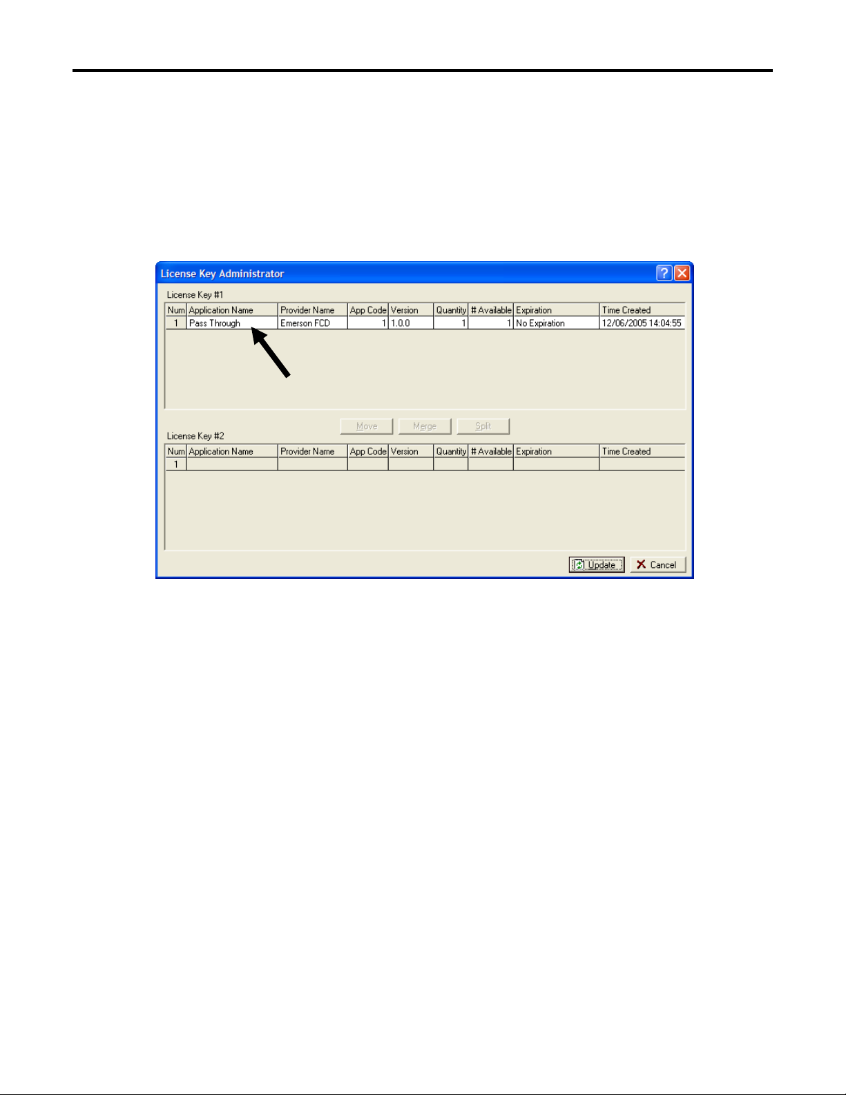
2.1.1 Verifying the License Key Installation
After you install the license key, you can verify whether the ROC800 recognizes the key. From the
ROCLINK 800 screen, select Utilities > License Key Administrator. The License Key Administrator
screen displays:
Figure 4. License Key Administrator
The Pass Through program appears in the Application Name column. (For further information on the
License Key Administrator screen, refer to the ROCLINK 800 Configuration Software User Manual,
Form A6121).
After you verify that the license key is correctly installed and recognized, proceed to Section 2.2.
2.2 Downloading the Program
This section provides instructions for installing the program into the Flash memory on the ROC800.
To download the program using ROCLINK 800 software:
1. Connect the ROC to your computer using the LOI port.
2. Start and logon to ROCLINK 800.
3. Select Utilities > User Program Administrator from the ROCLINK menu bar. The User
Program Administrator screen displays (see Figure 4):
Issued Mar-06 6
Page 10

Pass Through Program User Manual
Figure 5. User Program Administrator
4. Select any empty program number into which to download the program.
5. Click Browse in the Download User Program File frame. The Select User Program File screen
displays (see Figure 5).
6. Select the path and user program file to download from the CD-ROM. (Program files are
typically located in the Program Files folder on the CD-ROM). As Figure 5 shows, the screen
lists all valid user program files with the .TAR extension:
Issued Mar-06 7
Page 11

Pass Through Program User Manual
Figure 6. Select User Program File
7. Click Open to select the program file. The User Program Administrator screen displays. As
shown in Figure 6, note that the Download User Program File frame identifies the selected
program and that the Download & Start button is active:
Figure 7. User Program Administrator
8. Click Download & Start to begin loading the selected programs. The following message
displays:
Issued Mar-06 8
Page 12

Pass Through Program User Manual
Figure 8. Confirm Download
9. Click Yes to begin the download. When the download completes the following message
displays:
Figure 9. ROCLINK 800 Download Confirmation
10. Click OK. The User Program Administrator screen displays (see Figure 10). Note that:
The Device User Program Environment frame reflects the use of system memory.
The User Programs Installed in Device frame identifies the installed program(s).
Figure 10. User Program Administrator
11. Click Close. The ROCLINK 800 screen displays and the download is complete.
Issued Mar-06 9
Page 13

Pass Through Program User Manual
Figure 11. ROCLINK 800
Issued Mar-06 10
Page 14
Pass Through Program User Manual
3 CONFIGURATION
After you have loaded the Pass Through program on the ROC800, you configure the program using one
ROCLINK 800 screen and a program-specific screen (Pass Through Configuration):
Use ROCLINK 800’s Comm Port screen to associate the Pass Through program with a comm
port.
Use the program-specific Pass Through Configuration screen to configure all other program
parameters.
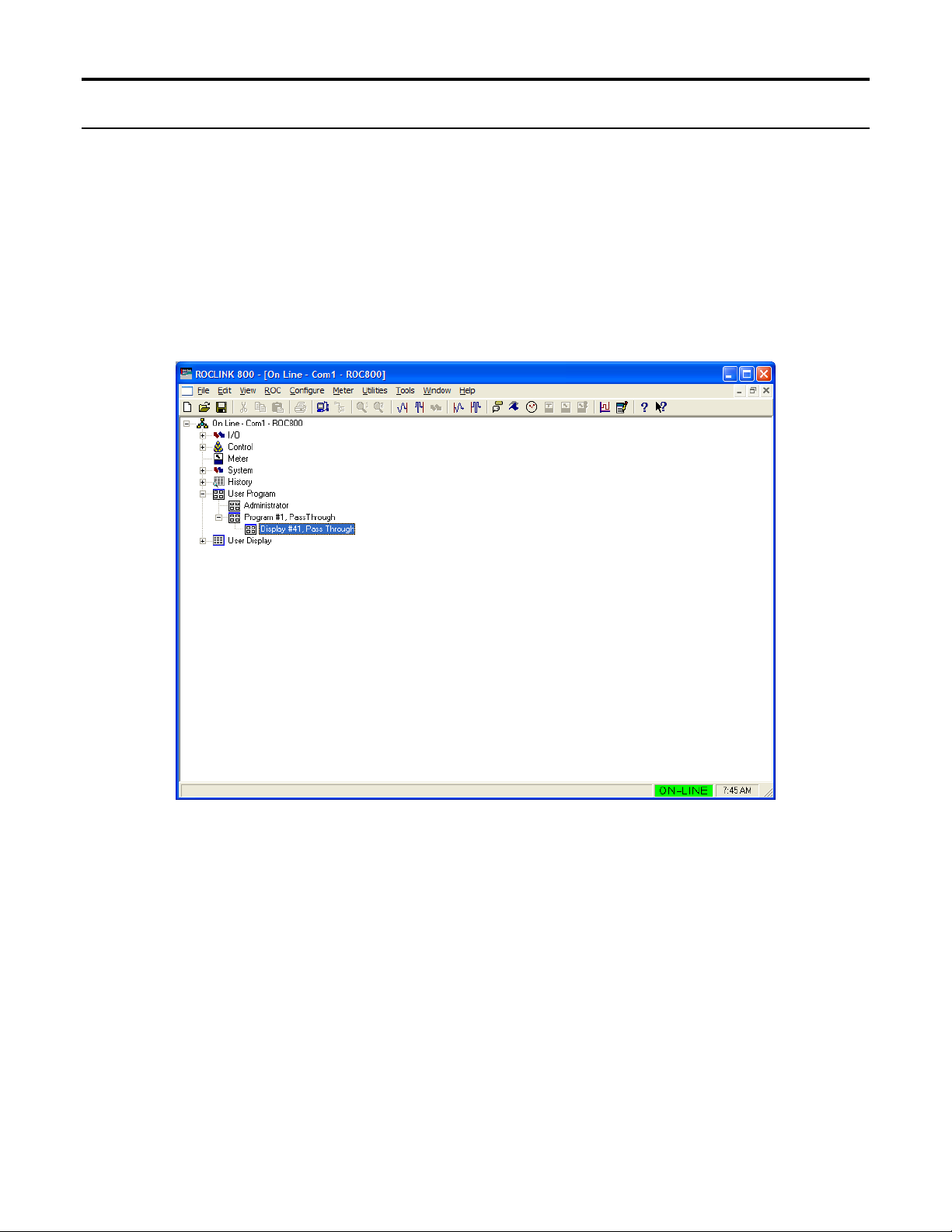
You can access the program-specific screen from the main ROCLINK 800 screen:
Figure 12. ROCLINK 800
Issued Mar-06 11
Page 15

Pass Through Program User Manual
3.1 Comm Port Screen
Use this screen to indicate the serial communications ports the external host (such as an HMI with an
OPC driver) uses when passing requests through the ROC800 to other communication ports.
Many other user programs use a one-to-one correlation between a communication port and a program.
This program permits a many-to-one correlation, allowing you associate multiple ports with the Pass
Through program. With different logical instances of this screen, you identify the communication ports
through which host requests come. You can ignore the Ethernet port (Comm1) since the Ethernet
program is configured to pass through host requests on one of the user displays installed with this
program.
Once you associate a communications port with a user program, you cannot use that port as a slave port
(a port through which the ROC800 passes host messages). For reference, ROC2 in Figure 1 has Comm2
and Comm3 designated as slave ports.
To access this screen:
1. From the ROCLINK 800 menu bar, select ROC > Comm Ports. The Comm Port screen
displays.
Figure 13. Comm Port
2. Select a comm port (in this example, COMM3) and associate it with the specific user program
number (in this case, User Program 1) that represents the Pass Through program.
Note: The program number may change, depending on where you have installed it.
3. Click Apply to save your changes. Proceed to Section 3.2.
Issued Mar-06 12
Page 16
Pass Through Program User Manual
3.2 Pass Through Configuration Screen
Use this screen to configure parameters for the Pass Through program. As you configure this program,
keep the following conditions (or “operational rules”) in mind:
A“host” port is any comm port to which a host connects with the intent of passing messages
through a slave port.
If you intend that a host connect to one or more serial ports, you must associate those ports with
the Pass Through program (see Section 3.1). You can associate multiple serial ports with the
program. Using the Pass Through Configuration screen, you can designate the Ethernet port as a
host port.
Note: SRBX is not supported for the comm port you associate with the Pass Through program.
You cannot designate a port as both slave and host. To assist in the configuration, the program
automatically “grays out” invalid selections.
For example, you associated Comm 3 with the program (see Section 3.1). Comm 3 is now
available for selection on any of the logical iterations of the Pass Through Configuration screen.
However, once you select Comm 3 on any logical iteration of the Pass Through Configuration
screen, the program prevents you from selecting it as a host on any other logical iteration and
grays the port out as a reminder.
Note: Use the tabs on the configuration screen (which represent logical iterations—or
“logicals”—of this program) to configure up to three unique pass-through scenarios.
Slaves can be slaves on any logical.
To access this screen:
1. From the Directory Tree, select User Program > Program #2, Pass Through.
Note: The program number may change depending on where you installed it.
2. Double-click Display #41, Pass Through. The Pass Through Configuration screen displays:
Issued Mar-06 13
Page 17
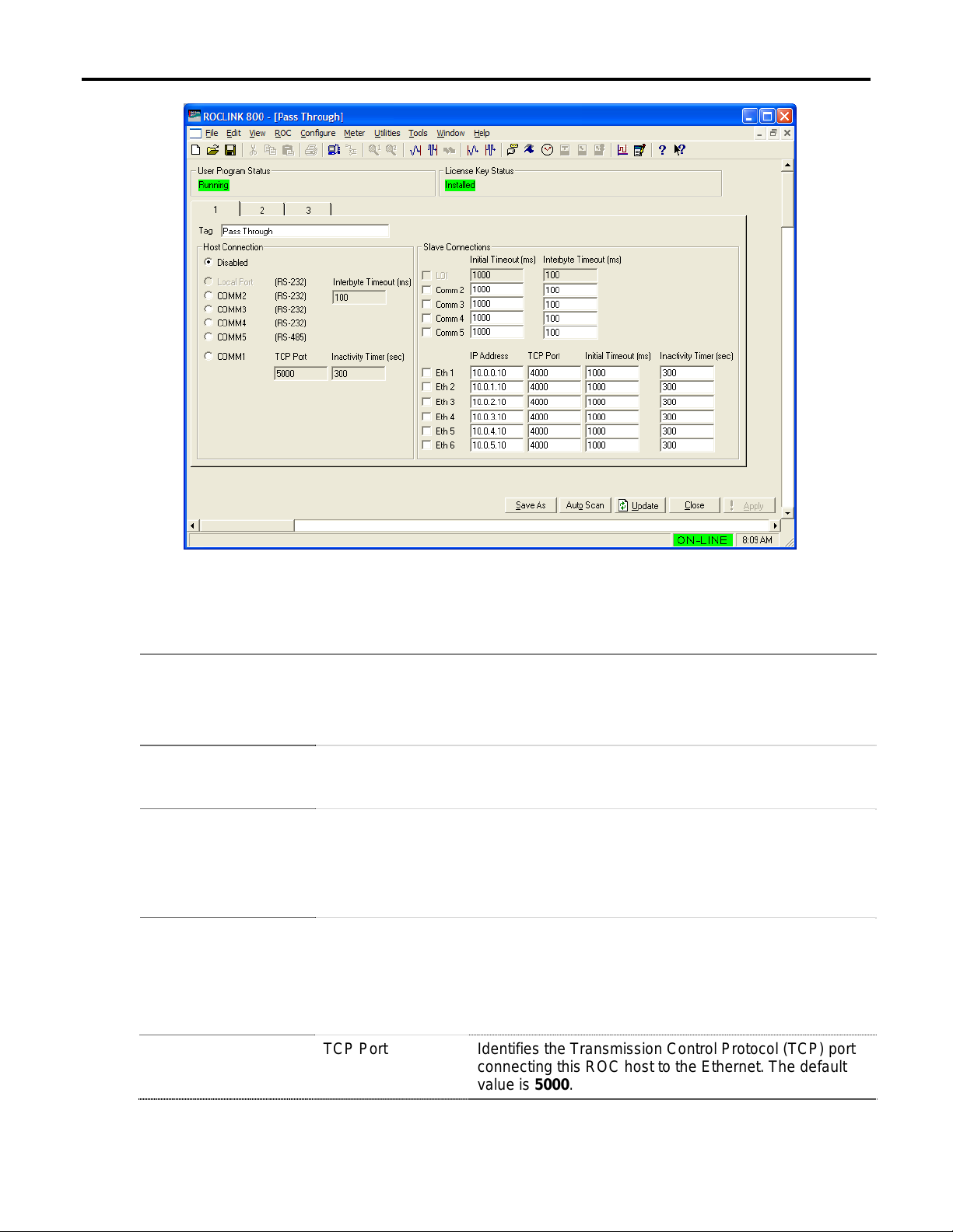
Pass Through Program User Manual
Figure 14. Pass Through Configuration
3. Review the values in the following fields:
Field Description
User Program Status
License Key Status
Tag
Host Connection
Indicates the program’s status. Valid values are Running (program is currently
available for use) or Loaded (program is installed but has not been started).
Note: To start this program, select Utilities > User Program Administrator.
Select the program and click Start.
Indicates whether the Pass Through license key is installed. Valid values are
Installed (license key is installed and recognized) or Key Not Found (license
key is not installed or is not installed correctly).
Provides a label for this pass-through scenario. Enter up to 40 alphanumeric
characters. The default tag is Pass Through.
Note: Using the tabs (1, 2, or 3) on this screen, you can define up to three
unique pass-through scenarios. Use the Tag field to uniquely identify each
scenario you define.
Indicates, for this logical iteration of the Pass Through Configuration screen,
which ports are available as host ports. The ports on this screen reflect the
associations you made on the Comm Port screen (see Section 3.1). The
program grays out any port you defined as a slave on another iteration of this
screen. Select Disabled to prevent this ROC from responding to host
requests.
Issued Mar-06 14
TCP Port Identifies the Transmission Control Protocol (TCP) port
connecting this ROC host to the Ethernet. The default
value is 5000.
Page 18

Field Description
Host Connection
Inactivity Timer Sets, in seconds, how long the ROC host waits for a
(continued)
Pass Through Program User Manual
response before canceling the request. The default
value is 300.
Note: This program does not support retires.
Slave Connections
Interbyte Timeout Indicates, in milliseconds, the amount of time the ROC
host waits between portions of a response before
canceling the entire request and proceeding to the next
request. The default value is 100.
Note: To ensure response receipt, you may need to
tune this value to accommodate the baud rate and the
request volume for your environment.
Indicates, for this logical iteration of the Pass Through Configuration screen,
slave ports through which the program passes messages from host ports
identified on this same logical iteration of the screen.
Note: The program grays out any invalid comm port (“invalid” meaning the port
has previously been defined as a host port).
Initial Timeout Defines, in milliseconds, how long the master waits for a
response to a request on this connection. If the
response time exceeds the value you define, the master
goes to the next request in the serial message queue
and drops the first. You may need to tune this value to
accommodate the baud rate and the request volume for
your environment.
Note: This program does not support retries.
Interbyte Timeout Indicates, in milliseconds, the amount of time the ROC
host waits between portions of a response before
canceling the entire request and proceeding to the next
request.
Note: To ensure response receipt, you may need to
tune this value to accommodate the baud rate and the
request volume for your environment.
IP Address Defines an Internet Protocol (IP) address for up to six
Ethernet-based slave connections. The default values
for slave connections 1 through 6 are, respectively,
10.0.0.10, 10.0.1.10, 10.0.2.10, 10.0.3.10, 10.0.4.10,
and 10.0.5.10.
Note: 127.0.0.1 is an industry-standard IP address you
can enter to enable this ROC to respond to the host’s
request. It must be defined for the 4000 port to function.
TCP Port Defines a TCP port for the selected Ethernet-based
slave connection. The default value is 4000.
Issued Mar-06 15
Page 19

Field Description
Slave Connections
(continued)
Initial Timeout Defines, in milliseconds, how long the master waits for a
Pass Through Program User Manual
response to a request on this connection. The default
value is 1000.
If the response time exceeds the value you define, the
master goes to the next request in the serial message
queue and drops the first. You may need to tune this
value to accommodate the baud rate and the request
volume for your environment.
Note: This program does not support retries.
Inactivity Timer Sets, in seconds, how long the ROC host waits for a
response before canceling the request. The default
value is 300.
Note: This program does not support retires.
4. Click Apply to save any changes you have made to this screen.
5. Click OK to return to the ROCLINK 800 screen. Proceed to Section 3.3 to save the
configuration.
Issued Mar-06 16
Page 20

Pass Through Program User Manual
3.3 Saving the Configuration
Whenever you modify or change the configuration, it is a good practice to save the final configuration to
memory. To save the configuration:
1. Select ROC > Flags. The Flags screen displays:
Figure 15. Flags screen
2. Click Save Configuration. A verification message displays:
Figure 16. Perform screen
Issued Mar-06 17
Page 21

Pass Through Program User Manual
3. Click Yes. A confirmation message displays:
Figure 17. Flags screen
4. Click OK to begin the save process. The Status field on the Flags screen displays In Progress.
When the process ends, the Status field on the Flags screen displays Completed.
5. Click Update on the Flags screen. This completes the process of saving your new configuration.
Issued Mar-06 18
Page 22

Pass Through Program User Manual
4 REFERENCE MATERIALS
This section provides tables of information on the user-defined point type the Pass Through program
uses:
41 (Pass Through Configuration)
Issued Mar-06 19
Page 23

Pass Through Program User Manual
4.1 Point Type 41: Pass Through Configuration
Point type 41 is the Pass Through configuration point type. The program maintains 3 logical instances of this point type, and saves point type 41
to internal configuration memory.
Parm
#
0 Point Version R/O UINT32
1 Tag R/W String40 AC40 ‘Pass
2 Status R/O UINT8
3 Host Connection Type R/W UINT8
4 Host TCP Port R/W UINT16
5 Host TCP Inactivity
6 Host Interbyte Timeout R/W UINT32
7 LOI Slave Enable R/W UINT8
8 LOI Slave Initial Timeout R/W UINT32
9 LOI Slave Interbyte
10 CM2 Slave Enable R/W UINT8
11 CM2 Slave Initial
12 CM2 Slave Interbyte
13 CM3 Slave Enable R/W UINT8
14 CM3 Slave Initial
15 CM3 Slave Interbyte
16 CM4 Slave Enable R/W UINT8
17 CM4 Slave Initial
18 CM4 Slave Interbyte
19 CM5 Slave Enable R/W UINT8
Name Access
R/W UINT16
Timeout
R/W UINT32
Timeout
R/W UINT32
Timeout
R/W UINT32
Timeout
R/W UINT32
Timeout
R/W UINT32
Timeout
R/W UINT32
Timeout
R/W UINT32
Timeout
Data
Type
Range Default Version
4294967295
0
1
0
6 seconds
0
65535
0
65535 seconds
0
4294967295
0
1
0
4294967295
0
4294967295
0
1
0
4294967295
0
4294967295
0
1
0
4294967295
0
4294967295
0
1
0
4294967295
0
4294967295
0
1
0
1.00
1.00 Label for iteration
Through’
1.00
1.00 Indicates the comm port associated with the host.
5000 1.00 TCP port host connection uses
300 1.00 Indicates how long the host waits for a response
100 1.00 Indicates how long the host waits between
0 1.00 Enables or disables this port as a slave port.
1000 1.00 Indicates how long the host waits for a response to
100 1.00 Indicates how long the host waits between
0 1.00 Enables or disables this port as a slave port.
1000 1.00 Indicates how long the host waits for a response to
100 1.00 Indicates how long the host waits between
0 1.00 Enables or disables this port as a slave port.
1000 1.00 Indicates how long the host waits for a response to
100 1.00 Indicates how long the host waits between
0 1.00 Enables or disables this port as a slave port.
1000 1.00 Indicates how long the host waits for a response to
100 1.00 Indicates how long the host waits between
0 1.00 Enables or disables this port as a slave port.
Description of functionality and meaning of
values
before canceling the request.
portions of a response before canceling the
request.
a request on this connection.
portions of a response before cancelling the
request.
a request on this connection.
portions of a response before cancelling the
request.
a request on this connection.
portions of a response before cancelling the
request.
a request on this connection.
portions of a response before cancelling the
request.
Issued Mar-06 20
Page 24

Pass Through Program User Manual
Parm
#
20 CM5 Slave Initial
21 CM5 Slave Interbyte
22 TCP Slave 1 Enable R/W UINT8
23 TCP Slave 1 IP R/W String20 AC20 10.0.0.10 1.00 Indicates the IP address for this port.
24 TCP Slave 1 Port R/W UINT16
25 TCP Slave 1 Initial
26 TCP Slave 1 Inactivity
27 TCP Slave 2 Enable R/W UINT8
28 TCP Slave 2 IP R/W String20 AC20 10.0.1.10 1.00 Indicates the IP address for this port.
29 TCP Slave 2 Port R/W UINT16
30 TCP Slave 2 Initial
31 TCP Slave 2 Inactivity
32 TCP Slave 3 Enable R/W UINT8
33 TCP Slave 3 IP R/W String20
34 TCP Slave 3 Port R/W UINT16 AC20 4000 1.00 Indicates the TCP port for this slave connection.
35 TCP Slave 3 Initial
36 TCP Slave 3 Inactivity
37 TCP Slave 4 Enable R/W UINT8
38 TCP Slave 4 IP R/W String20 AC20 10.0.3.10 1.00 Indicates the IP address for this port.
39 TCP Slave 4 Port R/W UINT16
40 TCP Slave 4 Initial
41 TCP Slave 4 Inactivity
42 TCP Slave 5 Enable R/W UINT8
43 TCP Slave 5 IP R/W String20 AC20 10.0.4.10 1.00 Indicates the IP address for this port.
44 TCP Slave 5 Port R/W UINT16
45 TCP Slave 5 Initial
46 TCP Slave 5 Inactivity
47 TCP Slave 6 Enable R/W UINT8
48 TCP Slave 6 IP R/W String20 AC20 10.0.5.10 1.00 Indicates the IP address for this port.
49 TCP Slave 6 Port R/W UINT16
Name Access
R/W UINT32
Timeout
R/W UINT32
Timeout
R/W UINT32
Timeout
R/W UINT16
Timer
R/W UINT32
Timeout
R/W UINT16
Timer
R/W UINT32
Timeout
R/W UINT16
Timer
R/W UINT32
Timeout
R/W UINT16
Timer
R/W UINT32
Timeout
R/W UINT16
Timer
Data
Type
Range Default Version
4294967295
0
4294967295
0
1
0
65535
0
65535 mSec
0
65535 seconds
0
1
0
65535
0
65535 mSec
0
65535 seconds
0
1
0
65535
0
65535 mSec
0
65535 seconds
0
1
0
65535
0
65535 mSec
0
65535 seconds
0
1
0
65535
0
65535 mSec
0
65535 seconds
0
1
0
65535
0
1000 1.00 Indicates how long the host waits for a response to
100 1.00 Indicates how long the host waits between
0 1.00 Enables or disables this port as a slave port.
4000 1.00 Indicates the TCP port for this slave connection.
1000 1.00 Indicates how long the host waits for a response to
300 1.00 Indicates how long the host waits for a response
0 1.00 Enables or disables this port as a slave port.
4000 1.00 Indicates the TCP port for this slave connection.
1000 1.00 Indicates how long the host waits for a response to
300 1.00 Indicates how long the host waits for a response
0 1.00 Enables or disables this port as a slave port.
10.0.2.10 1.00 Indicates the IP address for this port.
1000 1.00 Indicates how long the host waits for a response to
300 1.00 Indicates how long the host waits for a response
0 1.00 Enables or disables this port as a slave port.
4000 1.00 Indicates the TCP port for this slave connection.
1000 1.00 Indicates how long the host waits for a response to
300 1.00 Indicates how long the host waits for a response
0 1.00 Enables or disables this port as a slave port.
4000 1.00 Indicates the TCP port for this slave connection.
1000 1.00 Indicates how long the host waits for a response to
300 1.00 Indicates how long the host waits for a response
0 1.00 Enables or disables this port as a slave port.
4000 1.00 Indicates the TCP port for this slave connection.
Description of functionality and meaning of
values
a request on this connection.
portions of a response before cancelling the
request.
a request.
before canceling the request.
a request.
before canceling the request.
a request.
before canceling the request.
a request.
before canceling the request.
a request.
before canceling the request.
Issued Mar-06 21
Page 25

Pass Through Program User Manual
Parm
#
50 TCP Slave 6 Initial
51 TCP Slave 6 Inactivity
Name Access
R/W UINT32
Timeout
R/W UINT16
Timer
Data
Type
Range Default Version
65535 mSec
0
65535 seconds
0
1000 1.00 Indicates how long the host waits for a response to
300 1.00 Indicates how long the host waits for a response
Description of functionality and meaning of
values
a request.
before canceling the request.
Issued Mar-06 22
Page 26

Pass Through Program User Manual
If you have comments or questions regarding this manual, please direct them to your local sales representative or
contact:
Emerson Process Management
Flow Computer Division
Marshalltown, Iowa 50158 USA
Houston, TX 77065 USA
Pickering, North Yorkshire UK Y018 7JA
Website: www.EmersonProcess.com/flow
Issued Mar-06 23
 Loading...