

Page 1

s
User Manual
Document: D5120
Part: D301421X012
May 2013
OpenBSI Harvester Manual
OpenBSI Version 5.9
Remote Automa ti on Solution
www.EmersonProcess.com/Remote
Page 2

Be sure that these instructions are carefully read and understood before any operation is
attempted. Improper use of this device in some applications may result in damage or injury. The
user is urged to keep this book filed in a convenient location for future reference.
These instructions may not cover all details or variations in equipment or cover every possible
situation to be met in connection with installation, operation or maintenance. Should problems arise
that are not covered sufficiently in the text, the purchaser is advised to contact Emerson Process
Management, Remote Automation Solutions for further information.
IMPORTANT! READ INSTRUCTIONS BEFORE STARTING!
EQUIPMENT APPLICATION WARNING
The customer should note that a failure of this instrument or system, for whatever reason, may
leave an operating process without protection. Depending upon the application, this could result in
possible damage to property or injury to persons. It is suggested that the purchaser review the
need for additional backup equipment or provide alternate means of protection such as alarm
devices, output limiting, fail-safe valves, relief valves, emergency shutoffs, emergency switches,
etc. If additional information is required, the purchaser is advised to contact Remote Automation
Solutions.
RETURNED EQUIPMENT WARNING
When returning any equipment to Remote Automation Solutions for repairs or evaluation,
please note the following: The party sending such materials is responsible to ensure that the
materials returned to Remote Automation Solutions are clean to safe levels, as such levels are
defined and/or determined by applicable federal, state and/or local law regulations or codes. Such
party agrees to indemnify Remote Automation Solutions and save Remote Automation Solutions
harmless from any liability or damage which Remote Automation Solutions may incur or suffer due
to such party's failure to so act.
ELECTRICAL GROUNDING
Metal enclosures and exposed metal parts of electrical instruments must be gr ounded in
accordance with OSHA rules and regulations pertaining to "Design Safety Standards for Electrical
Systems," 29 CFR, Part 1910, Subpart S, dated: April 16, 1981 (OSHA rulings are in agreement
with the National Electrical Code).
The grounding requirement is also applicable to mechanical or pneumatic instruments that
include electrically operated devices such as lights, switches, relays, alarms, or chart drives.
EQUIPMENT DAMAGE FROM ELECTROSTATIC DISCHARGE VOLTAGE
This product contains sensitive electronic components that can be damaged by exposure to an
electrostatic discharge (ESD) voltage. Depending on the magnitude and duration of the ESD, this
can result in erratic operation or complete failure of the equipment. Read supplemental document
S14006 for proper care and handling of ESD-sensitive components.
Page 3

OpenBSI Harvester Manual
Contents
Introduction – What is the Harvester? 1
What types of data can be collected? .......................................................................... 1
What determines how often data is collected? ........................................................... 2
What happens to the data once it is collected? ........................................................... 2
Overview of Steps Which Must be Completed to Successfully Use the Harvester . 3
Installing the Software 5
Configuring Your Controller to Work with the Harvester 6
EGM 3530-10A, EGM 3530-50A TeleFlow™ Users .................................................. 6
DPC 3330, DPC 3335, RTU 3305, RTU 3310, 3530B-series, GFC 3308,
ControlWave Users ....................................................................................................... 6
Data Arrays ............................................................................................................................ 7
Storage without Wrapping (Push Down Array) ........................................................ 7
Storage with Wrapping (Wrap Array) ....................................................................... 8
Storage in Wrap Multiple Arrays ............................................................................... 9
Raw Array ................................................................................................................... 10
Archive Files ......................................................................................................................... 10
EAudit Module, Audit Function Block .............................................................................. 11
Signal Lists, Configuration Signal List .............................................................................. 11
Radio Turn ON Time Logic ................................................................................................ 11
Logical Signals to Regulate Data Collection & Modem Control ..................................... 12
Communications Off Signal ....................................................................................... 13
Maintenance Mode Signal .......................................................................................... 13
Force List Collection Signal ....................................................................................... 13
Modem Control Signals .............................................................................................. 13
Starting the Harvester 14
Defining Common Lists 15
Changing a signal Name already in a Common List ............................................... 16
Deleting a signal Name already in a Common List .................................................. 16
Deleting an entire Common List ................................................................................ 16
Exiting the Common List Configuration dialog box ............................................... 16
Adding a Controller and Configuring Collections 17
Adding the Controller ................................................................................................ 17
Node Configuration - General Page .......................................................................... 19
Node Configuration - Scheduling Page ..................................................................... 22
Node Configuration - Collections Page ..................................................................... 25
Adding a new Collection for this Controller ............................................................ 25
Modifying an existing Collection ............................................................................... 25
Issued May-2013 Contents iii
Page 4

OpenBSI Harvester Manual
Deleting an existing collection ....................................................................................25
Using the Collection Configuration Dialog Box ........................................................26
Defining / Modifying an Archive Collection: ............................................................26
Defining / Modifying an Audit Collection: ................................................................28
Defining / Modifying a Signal List Collection:..........................................................29
Defining / Modifying a Pushdown Array Collection: ...............................................30
Defining / Modifying a Raw Array Collection: .........................................................31
Defining / Modifying a Wrap Array Collection: ......................................................32
Defining / Modifying a Wrap Multiple Array Collection: .......................................33
Specifying Distributed User On-Times (OpenBSI 5.0 and newer) .........................35
Modifying the Configuration for a Controller 37
Deleting a Controller 37
Defining System Information 38
Monitoring the Status of Your Collections 42
Controllers with Collection Errors ............................................................................44
Viewing / Hiding the Tool Bar ....................................................................................45
Viewing / Hiding the Status Bar .................................................................................45
Viewing a List of the Controllers in which a Collection is Occurring Right Now.45
Viewing a List of Controllers which are experiencing Communication Errors or
other Failures ...............................................................................................................46
Viewing a list of Debugging Messages .......................................................................47
Placing a controller into Maintenance Mode 47
Viewing the List of Controllers Currently in Maintenance Mode ..........................48
Taking a Controller Out of Maintenance Mode .......................................................48
Turning on Polling for a Particular Controller 49
Performing an 'On Demand' Collection 49
Clearing Error, Status, and Timestamp Information using ‘Init Collection’ 49
Appendix A - Writing File Data to Signals A-1
Appendix B - File Naming Conventions B-1
Appendix C - Sample ACCOL Task for Radio Control C-1
Appendix D - Harvester Database Tables D-1
iv Contents Issued May-2013
Page 5

OpenBSI Harvester Manual
Appendix E – HARVESTER Initialization Files E-1
Appendix F - Harvester Error Messages F-1
Addendum – Using the Data File Conversion Utility
Issued May-2013 Contents v
Page 6

This page is intentionally left blank
Page 7

Introduction - What is the Harvester?
PC workstation running
Open BSI and Harvester
software (plus HMI software
e.g. OpenEnterprise)
Radio connection
Cable or dial-up
connections
Network 3000 Flow
computers/correctors
Network 3000
controller
Network 3000
controller
Network 3000
controller
ControlWave
controller
ControlWave
controller
Introduction – What is the Harvester?
The Harvester is a utility which allows collection of historical data from a network of
ControlWave and Network 3000 controllers. It combines many of the features of the OpenBSI
Scheduler and OpenBSI Data Collector programs, available in earlier releases of OpenBSI.
What types of data can be collected?
This historical data which can be collected by the Harvester includes:
• Data array values
• Archives
• Audit data (alarms and/or events)
• Lists (typically containing configuration data)
The Harvester can be used with Network 3000 series controllers (DPC 3330, TeleFlow, etc.) as
well as the ControlWave series of controllers.
1 OpenBSI Harvester
Page 8
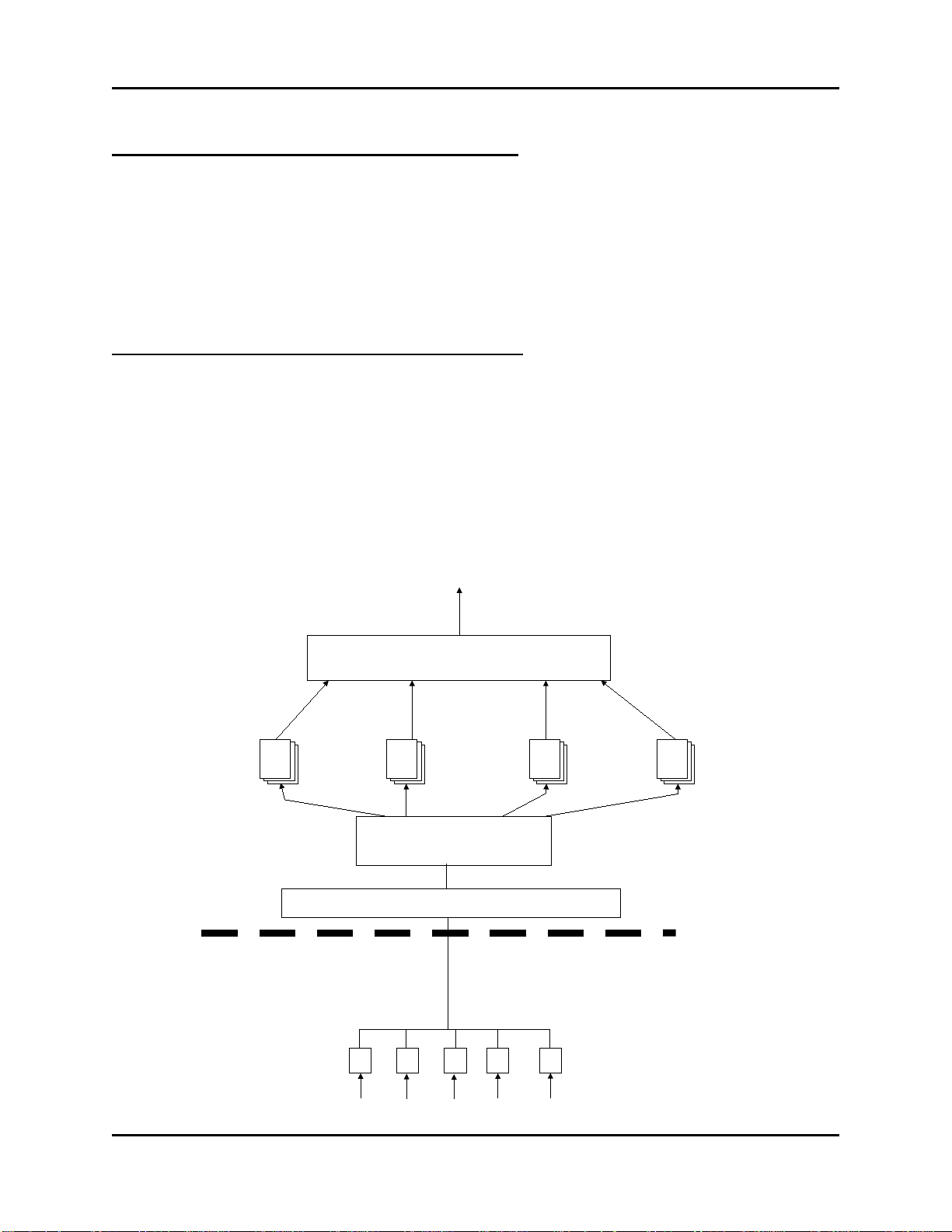
Introduction - What is the Harvester?
Controller
Network
Communication Link
(direct cable connection,
dial-up modem, or radio)
Inputs from field instrumentation
Open BSI Communications Layer
PC
Harvester
Array
data
files
Archive
data
files
Audit
data
files
List
data
files
Data File Conversion Utility
Export to OpenEnterprise,
Access, Excel, etc.
What determines how often data is collected?
Data can be collected at scheduled intervals e.g. hourly, or at a specified set of up to ten times
during the day, or based on a pre-defined collection scheme which takes into account various
factors affecting communications.
OpenBSI communications must be active for collections to occur.
What happens to the data once it is collected?
The data collected by the Harvester is stored in files at the PC workstation. These files can be
converted to a variety of formats using the OpenBSI Data File Conversion Utility, making them
accessible to other programs:
• OpenEnterprise database
• Comma Separated Variable format (CSV) - for use in Microsoft® Excel
• Coastal Flow Measurement's Flow-Cal™ package
• ODBC - for use in Microsoft® Access
OpenBSI Harvester 2
Page 9

Introduction - What is the Harvester?
NOTE:
which simplify data management, and make data collection more efficient.
Overview of Steps Which Must be Completed to Successfully Use the Harvester
1. The OpenBSI Network Edition, and the Harvester kit must be installed on your PC
workstation. In addition, if this is a new system, you will need the ControlWave Designer
kit, and/or the ACCOL Workbench kit, to create a control strategy which will execute in
the controller.
2. Create structures in your control strategy which will hold the data you want to collect
with the Harvester. These structures can include lists, arrays, archives, or audit trail. You
may find it advantageous to use the same signal names, list numbers, array numbers, and
archive numbers in each controller you configure, since this can simplify your
configuration activities later on.
We strongly recommend you consider using Archives instead of Arrays, because
Archives are more versatile. Archives include sequence numbers and timestamps
3. Create necessary configuration signals in each control strategy. These are used for modem
control, and to set various modes of operation for the controller, when it is used with the
Harvester. Again, you may find it advantageous to use the same configuration signal
names in each controller.
4. Download the completed and compiled control strategy files (ACCOL or ControlWave)
into each controller.
5. Configure your controller network. Before attempting to use the Harvester, you must have
an existing network of controllers to communicate with. These controllers must exist in
your NETDEF database. Verify that communications between the PC and the controller
network are functioning properly before trying to configure and use the Harvester.
6. Start the Harvester software, and sign on.
7. If you used lists with the same list numbers and signal names, you can configure common
lists at this point, otherwise, skip this step.
8. Add new node(s), and configure the node(s) using the Node Configuration pages, and the
Collection Configuration dialog box.
9. Edit the system information to specify the locations where Harvester files should be
output, and if you are using the scan interval for your on-time method, specify its
associated parameters.
3 OpenBSI Harvester
Page 10

Introduction - What is the Harvester?
10. Examine the status of your collections in the monitor window.
11. Configure the OpenBSI Data File Conversion Utility to set up export of the Harvester
data files to formats which may be exported to OpenEnterprise or various third-party
packages.
OpenBSI Harvester 4
Page 11

Installing the Softw are
Installing the Softw are
The Harvester software is included on the OpenBSI CD-ROM.
To install it, choose “Install OpenBSI” from the choices provided in the CD browser, and then
select “Harvester”. If it isn’t already installed, you should also select “Network Edition”.
Continue with the installation by following the directions onscreen. For more information on the
installation process, and on other software packages, see Chapter 2 of the OpenBSI Utilities
Manual (document# D5081).
5 OpenBSI Harvester
Page 12

Configuring Your Controller
Configuring Your Controller to Work with the Harvester
Before attempting to use the OpenBSI Harvester, your controller network must already be 'up and
running', and collecting data from field instrumentation. Instructions for setting up each
controller are included in the hardware manual accompanying the device.
The node name for each and every controller must exist in the Network Definition (NETDEF)
files. During later stages of configuration, you will need to know the node name, local address,
and expanded node addressing group number (if applicable) for each controller.
EGM 3530-10A, EGM 3530-50A TeleFlow™ Users
If you are using an EGM 3530-10A or -50A TeleFlow™ electronic gas measuring computer, it is
already pre-configured with the required signals, signal lists, Audit Trail, and archive structures;
if you need to alter the configuration, please contact our Technical Support Group for assistance.
DPC 3330, DPC 3335, RTU 3305, RTU 3310, 3530B-series, GFC 3308, ControlWave Users
If you are using Network 3000-series DPC 3330, DPC 3335, RTU 3305, RTU 3310, 'B' or newer
3530-series units supporting ACCOL, or a GFC 3308 unit, the ACCOL load running in the unit
must be configured with certain structures. Similar structures must also be created if you are
using a ControlWave controller running one of the IEC 61131 languages.
These structures (data arrays, the EAudit Module (or AUDIT function block for ControlWave),
signal lists, and signals) are discussed, briefly, below:
OpenBSI Harvester 6
Page 13
Configuring Your Controller
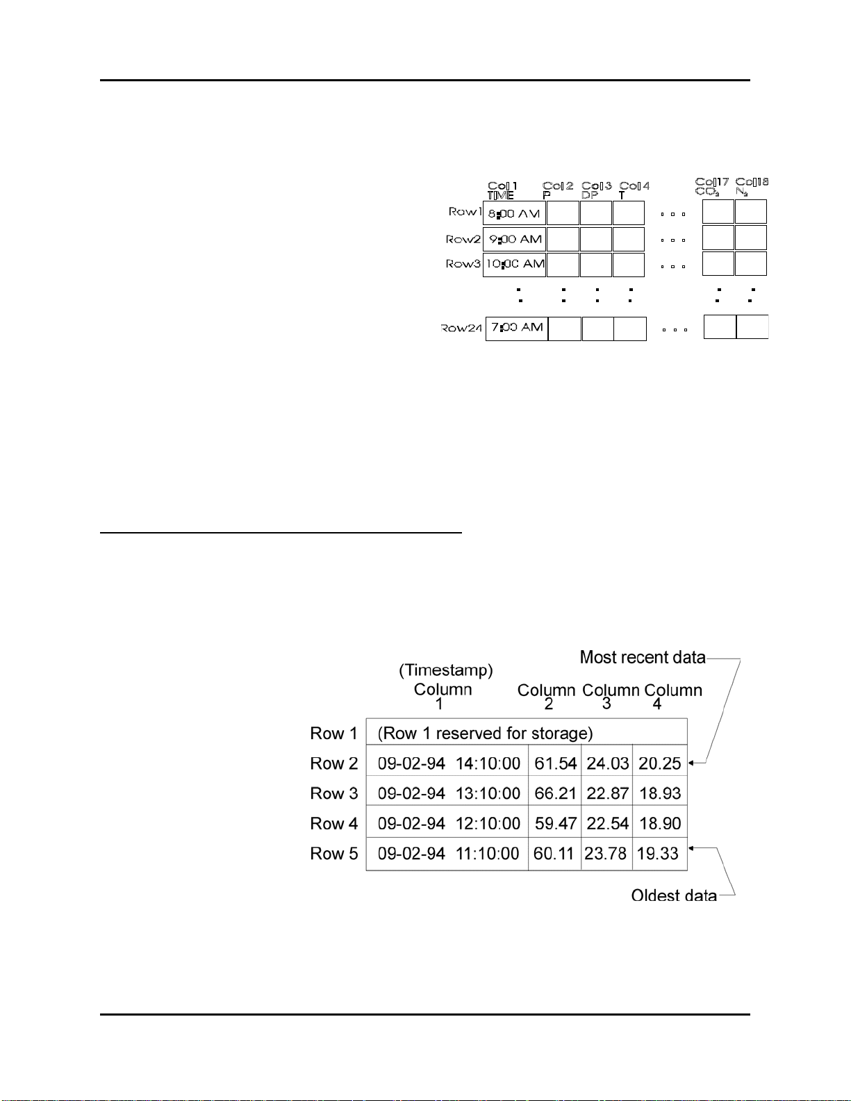
Data Arrays
The Harvester collects data from an analog readwrite data array, or from multiple such arrays
which share the same row/column dimensions.
These arrays are used to hold historical data.
In most cases, the first column of each analog
read-write array must contain a timestamp in the
Julian format of the ACCOL system signal
#TIME.000 or the ControlWave _TIME_000
variable.
The remaining columns of each array row contain the actual data collected at the time designated
by the timestamp in column 1. An example array is shown, above, which contains hourly flow
data from a natural gas pipeline. The type of data in the array will vary depending upon your
particular application.
There are four basic methods of array storage, each of which is discussed, below:
Storage without Wrapping (Push Down Array)
Storage without wrapping means that the most recent data is always stored in row 2 of the data
array; and as new data is entered, the previous data in row n is moved to row n+1, with the data
in the last row of the array discarded. (Note: Row 1 is reserved for temporary storage of running
totals.)
The pictures at right
illustrate this concept by
showing two snapshots of a 5
row by 4 column data array.
In the first picture, the most
recent data has a time stamp
of September 2, 1994 at 2:10
PM and is in row 2.
7 OpenBSI Harvester
Page 14
Configuring Your Controller
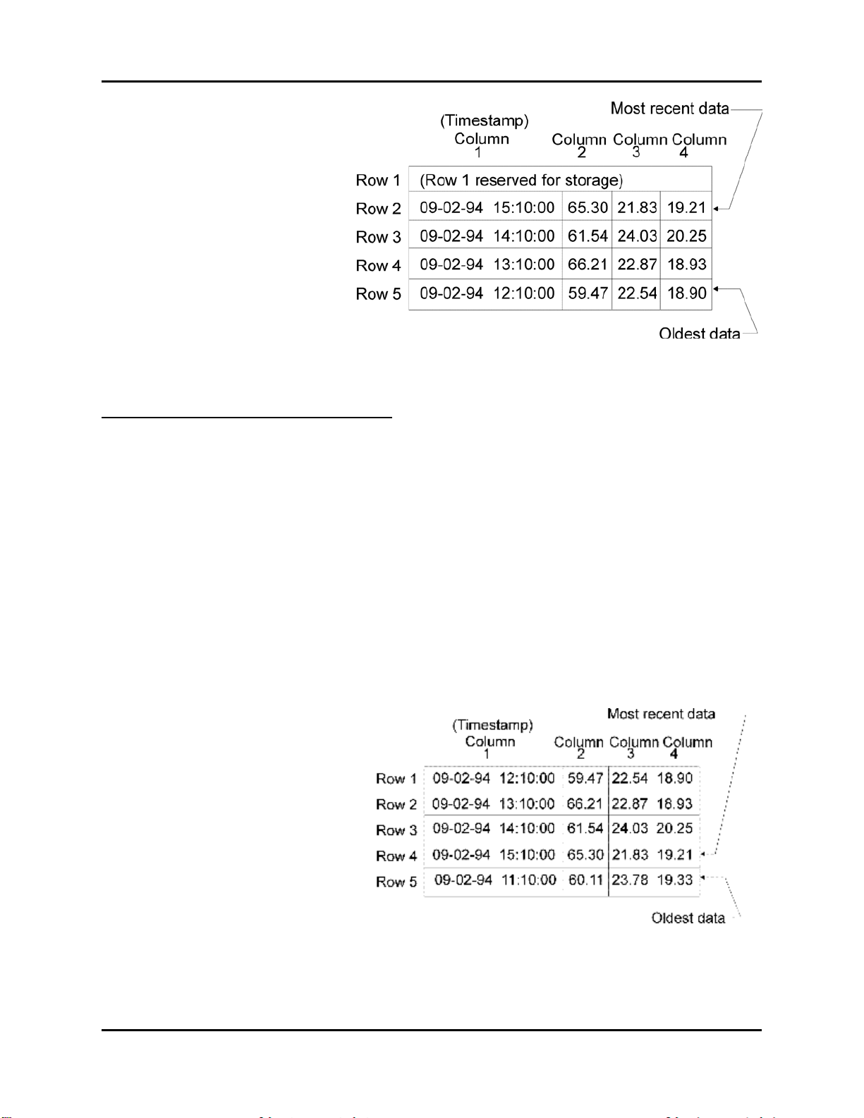
In the second picture, new data has
been collected, at 3:10 PM,
pushing the 2:10 PM data down
into row 3, the row 3 data into row
4, and the row 4 data into row 5.
The previous data that had been in
row 5 is discarded.
Storage with Wrapping (Wrap Array)
Storage with wrapping means that if the most recent data is currently in row n of the data array,
the next data will be stored in row n+1, unless row n is the last row of the array, in which case,
the next data will go to row 1. This wrap-around method is also referred to as a 'circular' array.
In this way, the oldest data is always overwritten with the newest data. When configuring this
array, data should always be stored beginning with Row 1. In addition, data must be stored in the
array at regular intervals, which are less than or equal to the specified scan interval. (Scan
intervals are discussed later in this manual.)
The pictures, below, illustrate the wrap array concept by showing three snapshots of a 5 row by 4
column data array.
In the first snapshot, the most recent
data has a time stamp of September 2,
1994 at 3:10 PM and is in the fourth
row.
OpenBSI Harvester 8
Page 15

Configuring Your Controller
In the second picture, new data has
been collected, at 4:10 PM,
overwriting the oldest data (i.e.
11:10 AM data which had been in
row 5). The 12:10 PM data in row 1
is now the oldest.
In the third picture, new data is
collected again. It would be stored
in Row 6, except there isn't one, so
the array wraps-around and it is
stored in Row 1. Now the oldest
data, which was the 12:10 PM data
in row 1, has been over-written
with the most recent data, from
5:10 PM. The next collection will
overwrite Row 2, and so on.
Storage in Wrap Multiple Arrays
The final method of data array storage is typically used in applications involving large amounts
of data, such as gas flow metering, using the GFC 3308 AccuRate Gas Flow Computer with its
standard ACCOL load. In this type of application, arrays in the GFC 3308 unit's ACCOL load are
configured to store data on an hourly basis, and each array has 24 rows, one for each hour in the
24 hour period corresponding to a 'gas day.' When the gas day ends, i.e. the first array is full, new
data is stored in another array, until that array is full, and then still another array is used. (See the
figure, below.)
9 OpenBSI Harvester
Page 16

Configuring Your Controller
IMPORTANT
rd ACCOL load for the GFC 3308, or you
create a load of your own, remember that multiple array collection can only
be performed if each and every array to be collected has th e exact sam e row /
izes through
multiple collection will cause the Harvester to terminate its collection. In
addition, when multiple arrays are to be collected, they must be numbered
This process continues until some pre-defined number of arrays has been filled, at which time,
the process will start over again. (This is similar to the wrapping discussed earlier, except instead
of wrapping around within a single array, wrapping occurs to another array.) When configuring
these arrays in ACCOL, data should always be stored beginning with Row 1 of the first array.
When wrapping to another array, storage should also always begin with Row 1. Data must be
stored at regular intervals, which are less than or equal to the specified scan interval.
If you decide to modify the standa
column dimensions. Any attempt to collect arrays of different s
consecutively.
Raw Array
A Raw Array collection involves an array where the Harvester simply collects the entire array,
without regard to timestamps, or rows.
No matter which of the methods are used, the Harvester will collect the historical data from the
data arrays, at a pre-defined scan interval, and store the data in files on the PC hard disk.
Archive Files
As an alternative to using data arrays, some controllers support the use of historical archive files.
Archive files reside within the controller, and are similar to data arrays, except that each column
is directly associated with a particular signal, and each column also has a descriptive title. See the
'ARC_STORE' section of the ACCOL II Reference Manual (document# D4044) for details.
ControlWave users should see the ControlWave Designer on-line help for the ‘ARCHIVE’
function block.
Wherever possible, we strongly recommend you use Archive Files for your historical storage.
NOTE: When using the Harvester to collect Archive Files in a BSAP network, the archive
records to be displayed must be 220 bytes or less. This is explained in more detail later in this
manual.
OpenBSI Harvester 10
Page 17

Configuring Your Controller
EAudit Module, Audit Function Block
ACCOL users must configure the Extended Audit Trail Module (EAudit).1 This module is used
to record alarm and event conditions, and is discussed in detail in the 'Audit Trail /EAudit'
section of the ACCOL II Reference Manual (document# D4044.) Similarly, ControlWave users
must configure the AUDIT function block. See the ControlWave Designer on-line help in
ControlWave Designer for details.
The alarm/event data is collected by the Harvester, and stored in files on the PC hard disk.
Signal Lists, Conf iguration Signal List
The Harvester can collect signal lists. One of these lists may be the Configuration Signal List
which contains any configuration parameters related to your particular application. The
configuration list generally contains information which does not change often, because it is
normally collected only on system startup, if a change occurs, or if the operator explicitly
requests that it be collected. In a natural gas pipeline application, for example, this list might
contain signals whose values represent pipe diameters, or orifice types.
NOTE: Signal lists collected via the Harvester cannot have more than 1000 signals.
Radio Turn ON Time Logic
If you are using radios as your communication link, your program must include user-defined
logic to turn ON its radio, at a pre-determined time, so as to be ready for data collection from the
Harvester. This pre-determined time is calculated based on the node's local address, its expanded
node addressing group number, and various parameters defined in the Harvester. Appendix C of
this manual includes a sample ACCOL task which may be used to turn on a Network 3000
controller's radio at a scheduled time. For information on the turn on logic for the Harvester
program, see the box, below:
1
Protected mode firmware (PLS00/PLX00 or newer) currently only supports use of the EAudit Module. 186-based
units (except for the 3308) with AL (or newer firmware) or 386EX Real Mode units with RMS02 (or newer
firmware) can be used with either the Audit Module, or the EAudit Module.
11 OpenBSI Harvester
Page 18

Configuring Your Controller
Calcul ati on of N ode Turn ON Time, A ctu al Colle ct i on Time
Turn ON T im e = Start T ime Off set + ([ Loc al Address - 1] * Poll Tim e Per Node)+
(Expanded Node Addressing G roup N o.)* (Po ll Time Per Group )
A ctual Start o f Co llec tio n = Turn ON Time + T urn on Delay
So, f or example, if:
Start Time O f fset = 1 se cond
Poll Time Per No de = 20 seconds
Poll Time Per Group = 5 sec onds
Turn on D elay = 5 se conds
Then, the c o ntro ller w ith the group # and local address # show n, will turn ON at
the time w ithin the scan interval shown:
Gro up #
L ocal A ddress #
Turn ON time
A ctual Start of
Collection
0 1 1 second 6 seconds
0 2 21 seco nds 26 seconds
0 3 41 seco nds 46 seconds
1 1 6 seconds 11 seconds
1 2 26 seco nds 31 seconds
1 3 46 seco nds 51 seconds
2 1 11 seco nds 16 seconds
2 2 31 seco nds 36 seconds
2 3 51 seco nds 56 seconds
Logical Signals t o Re gulate Data Collection & Modem Control
In addition to the signals collected via the signal lists, and turn ON time logic, each program
requires certain logical signals which are either used to notify the Harvester to perform a certain
function, or are used by the Harvester, to indicate it has performed a certain function. These
signals are as follows:
OpenBSI Harvester 12
Page 19

Configuring Your Controller
Communications Off Signal
This signal is turned ON by the Harvester to notify the controller that it has finished collecting
data for this scan interval. This can trigger user-defined logic which turns OFF the radio.
Maintenance Mode Signal
This signal is set ON by the Harvester monitor as a notification that the radio should not be
turned OFF, even if no collections are currently occurring. (This might be done so maintenance
or testing can be performed.)
Force List Collection Signal
This signal is set ON by user-defined logic in the program as a notification to the Harvester that
the configuration list has changed, somehow, and so it should be re-collected by the Harvester.
This signal MUST be designated for audit trail collection via the EAudit Module or AUDIT
function block.
Modem Control Signals
If the Harvester is collecting data from a slave controller which communicates to its master
controller in the network via a dial-up modem, the master must have a pair of logical (boolean)
signals for modem control. One signal is turned on by the Harvester (Request signal) to signify
that the master controller should dial-up its slave controller. The second signal (Confirm signal)
is turned on by the master controller to indicate that the dial-up connection with the slave node
has been established, thereby signifying to the Harvester, that collections can begin.
13 OpenBSI Harvester
Page 20

Starting the Harvester
r
r
r
Starting the Harvester
In order to start the Harvester, communications with the controller network must already be
active, via NetView. To start the Harvester, click as follows: StartProgramsOpenBSI
Tools Collection ProgramsHarvester
IMPORTANT: If this is the very first time the Harvester has been started
on this particular computer, you will be prompted to register the software.
Otherwise, the software can only be used for a maximum of 60 days. For
more information on the registration process, see Chapter 2 of the OpenBSI
Utilities Manual (document# D5081).
The Harvester Main Page will appear, as shown below:
Menu ba
Timestamp associated with most
recent collection
These sections of the screen
allow you to monitor information
about the status of the currently
configured collections.
Tool ba
Tree of
configured
controllers
Status ba
This window pane can display either a list of the active
nodes (controllers for which collections are occurring
right now) or a list of nodes which are in Maintenance
Mode, or a list of nodes which are experiencing
communication problems, or any current Harvester
debugging messges. You can select which items are
displayed either from icons in the tool bar or from the
“View” menu bar selection.
OpenBSI Harvester 14
Page 21

Defining Common Lists
Defining Common Lists
If you are running an identical application load/project in more than one controller, that contains
signals you want to collect, you can use Common Lists to simplify your collections. A common
list is just a group of signals you want to collect, in which the signals share the same name in
more than one controller. For example, if you have ten controllers, and each one has signals
named CURRENT.FLOW, CURRENT.TEMP, and CURRENT.PRESUR that you want to
collect, you could define a Common List containing these three signals. The advantage is that the
Common List is defined in only one place (the Harvester program itself); so as long as those
individual signals already exist in the your running application, you don’t need to modify your
application to add or change the Common List. Another advantage of using common lists is that
you save on certain communications overhead, because signal names do not need to be collected,
just the signal values.
To access the Common List Configuration dialog box, click on Edit Common Lists.
To create a common list, click on the [Add List] button.
The Enter Common List Number dialog box will appear.
Enter a number which will identify the common list, then
click on [OK].
15 OpenBSI Harvester
Page 22

Defining Common Lists
That list number will now appear in the "List" window on the left side of the Common List
Configuration dialog box. Click on it, and then click on either the [Insert After] or [Insert
Before] buttons to begin inserting signal names in the list.
The Enter Common List
Signal Name dialog box will
appear. Enter the name of the
first signal of the list, and
click on [OK].
That signal name will now appear in the "Signals" window on the right side of the Common
List Configuration dialog box. Repeat this process, using the [Insert After] button to insert
additional signals in the list. NOTE: The signal names and ordering of signals must match
exactly the corresponding signals in the controller's signal list.
The common list you define can be used, later, when you are defining a Signal List collection in
the Collection Configuration dialog box.
Changing a signal Name already in a Common List
To change the signal name of a signal already in the list, click on the signal, then click on the
[Modify] button. The Enter Common List Signal Name dialog box will re-appear, and you can
edit the signal name.
Deleting a signal Name already in a Common List
To delete the signal name of a signal already in the list, click on the signal, then click on the
[Delete] button. The signal name will be removed from the list.
Deleting an entire Common List
To delete an entire common list, click on the number of the list, in the "List" window of the
Common List Configuration dialog box, then click on the [Delete List] button.
Exiting the Common List Configuration dialog box
To exit the Common List Configuration dialog box, click on the [Close] button.
OpenBSI Harvester 16
Page 23

Adding a Controller and Configuring Collections
First, select one of the controllers in this list. (This
Next, if configuration
Finally, click on [Add]
Adding a Controller and Configuring Collections
Before data can be collected from a controller, it must be added into the list of nodes accessible
by the Harvester, and certain configuration entries must be made.
Adding the Controller
To add a controller, click on the 'New Node' icon, shown above, or click on File New Node
from the menu bar. The Add Nodes dialog box will appear.
list is all controllers in your NETDEF file which have
NOT yet been defined in the Harvester.)
details for the controller
(e.g. numbers of structures
used in the collections,
configuration signals, etc.)
are identical with a
controller you already
defined, choose that
controller’s name from the
“Default Config” list box.
to bring up the Node
Configuration pages.
17 OpenBSI Harvester
Page 24

Adding a Controller and Configuring Collections
• The "New Nodes" list box, displays a list of all controllers in your NETDEF database which
have NOT yet been configured for use with the Harvester. Select any one of these controllers
by clicking on it.
• Optionally, you can add multiple controllers at the same time by holding down the [Ctrl] key
as you select. This will cause all of the controllers you add to have the same collection
configuration parameters (you can alter them individually, after the initial configuration is
complete.) When you add multiple controllers via this method, you will prompted to enter an
"Auto Increment" value (in seconds).
If your collection method is 'Time
Interval', the "Auto Increment" is
used to space out collections if
collections from multiple
controllers are scheduled to occur
within the same interval.
(Otherwise the Harvester would
attempt to collect all the collections
at the same time, which could cause
communication problems.)
You can adjust the offset for individual nodes, later using the "Offset in seconds" parameter
described on page 23.
• Optionally, if you have already configured another controller with a similar configuration (for
example, it shares the same configuration signal names, and will use the same list, array
numbers, etc.) you can select its name from the "Default Config" list box. Once you have
selected a default configuration, common configuration details will be used for the new
controller you are adding.
• Finally, click on the [Add] button.
The Node Configuration pages will now appear. These pages allow you to enter various
configuration details, to choose how often your Harvester collections will be performed, and to
specify the type(s) of data to be collected by the Harvester from this particular controller.
OpenBSI Harvester 18
Page 25

Adding a Controller and Configuring Collections
Node
Enter a textual description of the node. For example, 'OAK
characters you enter will be displayed as the description.
Disable Collections
When checked, the Harvester will NOT attempt to make any
Skip Historical Collections
When checked, the Harvester will NOT attempt to perform an
Turn Off Polling after
Normally, if communications with a particular controller are via a
collections, polling would be turned off, and the modem would be
Node Configuration - General Page
The Node Configuration pages appear immediately after you add a new controller.
Identification
STREET COMPRESSOR STATION'. This will appear in the
Harvester "Node Information" window. Only the first 64
Flags
collections from this controller. This would typically be checked
if a controller has been temporarily taken out of service for
repairs, or if there are communication problems which must be
fixed prior to attempting collections.
on First Pass
initial array / archive collection on startup. Instead, it will wait for
the next calculated interval.
Collections
dial-up modem or radio, as soon as the Harvester completes its
19 OpenBSI Harvester
Page 26

Adding a Controller and Configuring Collections
hung up, because there is no reason to continue requesting data. If
Write to Station File
When checked, will automatically update the station file used by
to update the station file.
Communications Off
This signal is turned ON by the Harvester to notify the controller
Maintenance Mode Signal
This signal is set ON by the Harvester as a notification that the
Force List Collection
This signal is set ON by user-defined logic in the program as a
Username
RESERVED FOR FUTURE USE.
Password
RESERVED FOR FUTURE USE.
this box is NOT checked, however, polling will continue, even
after a collection has been completed. This can be useful if the
controller has a direct cable connection (i.e. it is always
connected.)
the OpenBSI Data File Conversion Utility. If no station file exists,
one will be created. NOTE: If there are multiple list, arrays, etc.
being collected from this controller, only the first one will be used
Communications Signals
Signal
Signal
ControlWave Security
Modem Control
If the Harvester is collecting data from a slave controller which communicates to its master
controller in the network via a dial-up modem, the master must have a pair of logical (boolean)
signals for modem control.
The Harvester will turn on the request signal, which should be used as a notification to execute
user-defined logic in the master for dialing up the slave node. When this is successfully done, the
user-defined logic should set the confirm signal to ON, as a notification to the Harvester that
collections from the slave node can proceed. The Harvester will check the confirm signal at a
OpenBSI Harvester 20
that it has finished collecting data for this scan interval. This can
trigger user-defined logic which turns OFF the radio.
radio should not be turned OFF, even if no collections are
currently occurring. (This might be done while maintenance or
testing is being performed.)
notification to the Harvester that the configuration list has
changed, somehow, and so it should be recollected by the
Harvester. This signal MUST be designated for audit trail
collection via the EAudit Module or AUDIT function block.
Page 27

Adding a Controller and Configuring Collections
Request Signal
The Harvester turns on the "Request Signal" in the Master node, to activate
Confirm
User-defined logic in the control strategy file must turn this signal on to notify
Retries
After setting the "Request Signal", this is the number of times the Harvester
Confirm Wait
After setting the "Request Signal", this is the length of time (in seconds) the
user-specified interval (see "Confirm Wait" and "Retries", below).
Signal
user-defined logic in the control strategy file, that will initiate a dial-up
operation to the Slave node.
the Harvester that the Slave node has been successfully dialed, and collections
can commence.
will check to see that the "Confirm Signal" has been turned ON.
Harvester will wait before checking to see that the "Confirm Signal" has
been turned ON. This same period applies to all "Retries" as well.
21 OpenBSI Harvester
Page 28
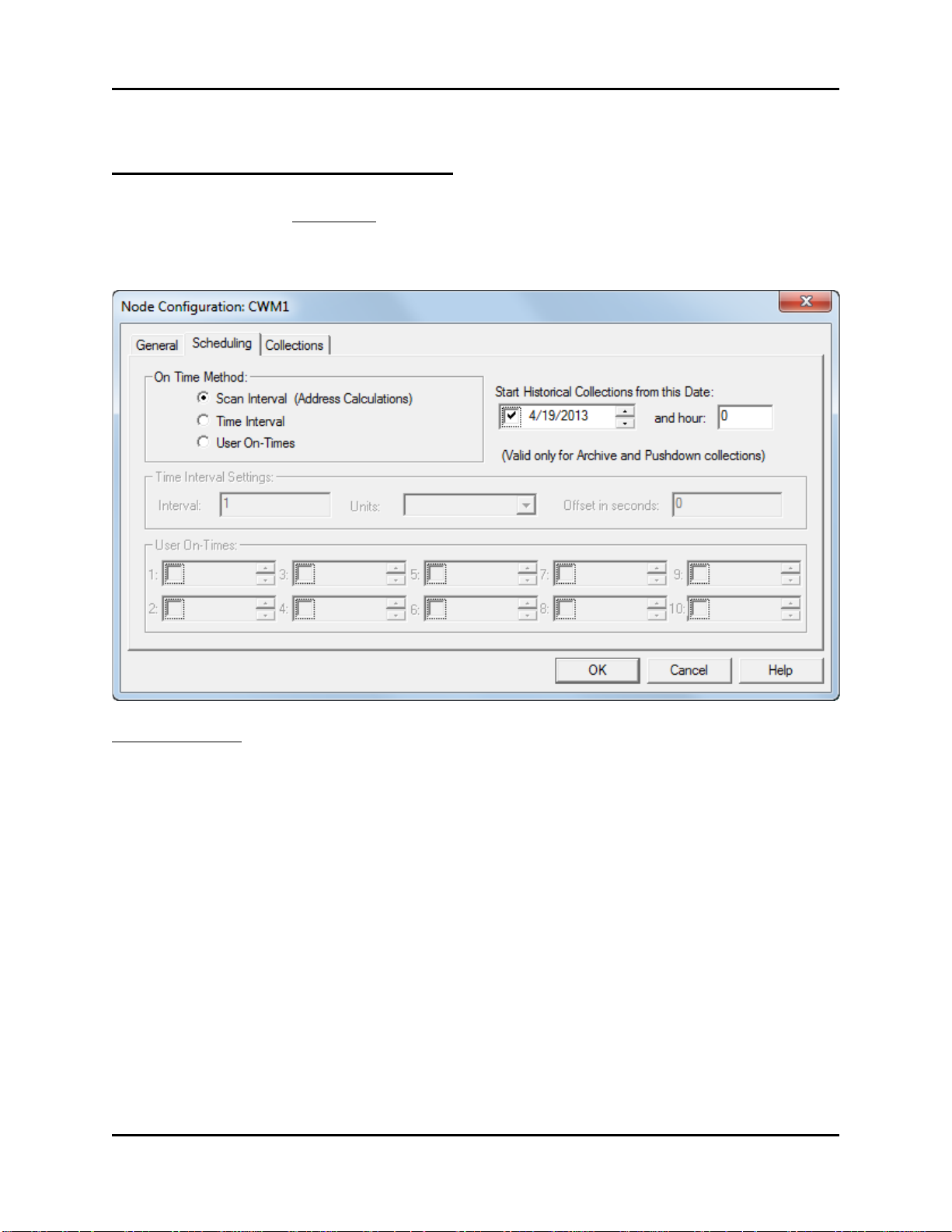
Adding a Controller and Configuring Collections
Scan Interval (Address
When this is chosen, the Harvester attempts to
Time Interval
When this is chosen, the Harvester attempts to
User On-Times
When this is chosen, the Harvester attempts to
below.
Node Configuration - Scheduling Page
NOTE: If you are using Distributed User On-Times (different from ‘User On-Times’ shown
below) skip the ‘Scheduling’ page. Distributed User On-Times is discussed later in this manual
in the ‘Specifying Distributed User On-Times’ section.
On Time Method
Only one On Time Method per controller may be used. There are three possible choices:
Calculations)
OpenBSI Harvester 22
communicate with a particular node based on its location
in the network, as determined by an address calculation.
communicate with a particular node every time a
particular period of time has expired, for example, every
hour. See "Timer Interval Settings" below.
communicate with a particular node at up to ten specified
times during the day. See the "User On-Times" section,
Page 29

Adding a Controller and Configuring Collections
Start Historical Collections from
If you have several days of pushdown array or archive
and hour
If you want to specify that this historical data that you
23). (Requires OpenBSI 5.9 or newer)
Interval
Together with the "Units" this defines the period of time between
Units
This defines the units of the interval. The possible choices are 'minutes',
Offset in seconds
This specifies a period of time in seconds (measured from the beginning of
occur within the same interval.
First, check this box
Now click on any part of
arrows to adjust the date.
Optionally specify a different
this Date:
data stored in the controller, this allows you to specify
the first date from this historical data from which you
want the collections to begin. Any stored data for dates
earlier than this will not be collected. (This applies only
to Archive and pushdown arrays.)
the date and type a new
date, or optionally use the
hour than midnight here.
To set the date, check the box next to the date, then
select one of the date fields, and either enter new
numbers for the date, or use the up-down controls on the
right to adjust the date as desired.
collect doesn’t start at the default of midnight (0) you
can specify a different hour here (in 24 hour format 0-
Time Interval Settings
collections. For example, if the "Interval" is set to 1, and "Units" is set to
'hours', then collections will occur every hour.
'hours' or 'days'.
the interval) that the Harvester will wait before beginning its collection. This
is often necessary if arrays or archives are being updated in the controller
every hour, and it is necessary to wait this number of seconds for the array /
archive manipulation to be completed. If left at 0, the collection will begin at
the very start of the interval. The offset can also be used to space out
collections, if several collections from multiple controllers are scheduled to
23 OpenBSI Harvester
Page 30

Adding a Controller and Configuring Collections
First, check this box
Now cl ick on any part o f
the time and type a new
time, or optionally use the
arrows to adjust the time.
User On-Times
If User On-Times is selected as the On-Time Method, up to 10 different times during the day can
be specified as times at which the Harvester should collect data from this controller. Use the
"User On-Times" boxes, shown, to specify a time for collection.
NOTE: If you have a large number of controllers, and do not want to manually enter on times for
each one, you can use an alternate method called Distributed User On-Times. This is discussed
later in this manual in the ‘Specifying Distributed User On-Times’ section.
Reducing Communication Message Traffic (OpenBSI 5.8 Service Pack 1 and newer only):
By default, Harvester collects column header information each collection pass. To prevent this
re-collection of column header data and thereby reduce the number of communication messages
per collection, you can use the Advanced Configuration tool to turn off re-collection of column
header information. This option can reduce communication costs if your communication link is
expensive, for example a satellite link.
To do this:
1. First start the Advanced Configuration tool by clicking OpenBSI Tools > Common
Tools > Advanced Configuration.
2. Then on the Harvester tab of the OpenBSI INI Configuration Settings dialog box, check
the “Do Not collect Column Header Information on Archive Collections” and click
“OK”. Harvester will not collect column header information on subsequent collections.
OpenBSI Harvester 24
Page 31

Adding a Controller and Configuring Collections
Node Configuration - Collections Page
The Collections page lists all currently configured collections for this controller, and also allows
you to configure additional collections
Adding a new Collection for this Controller
To add a collection, click on the [Add] button, then configure the collection in the Collection
Configuration dialog box. (See 'Using the Collection Configuration Dialog Box').
Modifying an existing Collection
To modify an existing collection, click on the line for that collection in the list of collections
window, then click on the [Modify] button to call up the Collection Configuration dialog box.
(See 'Using the Collection Configuration Dialog Box').
Deleting an existing collection
To delete an existing collection, click on the line for that collection in the list of collections
window, then click on the [Delete] button.
25 OpenBSI Harvester
Page 32

Adding a Controller and Configuring Collections
Collection Type
This must be set to 'Archive'.
Item Number
Enter the Archive File Number here.
ControlWave users: The Archive File must have been
Using the Collection Configuration Dialog Box
The Collection Configuration dialog box is accessible by clicking on the [Add] button from the
Node Configuration - Collections page. If you select an existing collection on that page, you can
call it up by clicking on the [Modify] button.
The fields visible in the Collection Configuration dialog box vary depending upon your choice of
"Collection Type". The available choices are: Archive, Audit, Pushdown Array, Raw Array,
Signal List, Wrap Array, Wrap Multiple Array. Each choice will be explained in a separate
section, below.
Defining / Modifying an Archive Collection:
Complete the fields as described, below, then
click on [OK]:
OpenBSI Harvester 26
Network 3000 users: The Archive File must have been
defined in ACCOL Workbench. The Archive File Number
must match the value on the ARCHIVE terminal of the
ARC_STORE module.
Page 33

Adding a Controller and Configuring Collections
defined using either the Flash Configuration Utility or the
ARCHIVE function block.
Flags
View TimeStamp in RTU Tree
When checked, will display the most recently collected
Communications
Max Rows Collected Per Pass
This specifies the maximum number of Archive Records
Collect all history using ‘Max
If your system is having communication problems, outside
(OpenBSI 5.4 and newer.)
Type of Data
Number of bytes required
Timestamp
4
Local Sequence Number
2
Global Sequence Number
2
Analog Floating Point value
4
Logical / BOOL value
1
Archive web page. The Archive File Number must match
the value on the iiArchiveNumber parameter in the
Disable
Max Retries Per Pass
Rows’ as maximum per message
When checked, will stop this collection from occurring.
timestamp ("Last Timestamp") from this controller, in the
tree of nodes on the left hand side of the main Harvester
window. NOTE: Even if there are multiple collections for a
controller, only one collection timestamp will be displayed.
This specifies the total number of attempts the Harvester
will make to collect data from this controller on a given
collection pass. A retry occurs if there is a communication
timeout.
(rows) which the Harvester will attempt to collect from the
controller on a given collection pass.
of OpenBSI, you may want to use this option. This
specifies that the Harvester should attempt to collect the
maximum number of Archive Records (as specified by the
parameter above) but it will do it using shorter messages.
NOTE: When using the Harvester to collect Archive Files in a BSAP network, the archive
records to be displayed must be 220 bytes or less. A total of 4 bytes of the 220 are already used to
display the timestamp, plus 2 bytes are used for the local sequence number, and 2 bytes are used
for the global sequence number. This leaves 212 bytes for other columns of data. This could
include up to 53 columns of floating point data.
27 OpenBSI Harvester
Page 34

Adding a Controller and Configuring Collections
Collection Type
This must be set to 'Audit'.
Flags
Communications
Special Parms
Harvester, they will be deleted from the controller.
Defining / Modifying an Audit Collection:
Complete the fields as described, below, then
click on [OK]:
Usage Notes:
If Harvester users select a [Demand Coll]
collection, all audit records which the
Harvester has not already collected, will be
brought back. If audit records have already
been collected and still exist at the RTU, they
will not be collected again.
If the [Init Collection] button has been
pressed, prior to a [Demand Coll] collection,
all audit records available at the RTU will be
brought back, whether or not they have been
collected previously.1
Disable
Max Retries Per Pass
Reset after Collection
1
Prior to OpenBSI 5.6 Service Pack 1, Harvester would collect all available audit records, whether or not they had
been collected earlier, unless the audit buffer had been reset, using the “Reset after Collection” option, to delete
records already collected.
OpenBSI Harvester 28
When checked, will stop this collection from occurring.
This specifies the total number of attempts the Harvester
will make to collect data from this controller on a given
collection pass. A retry occurs if there is a communication
timeout.
If checked, once audit records have been collected by the
Page 35

Adding a Controller and Configuring Collections
Collection Type
This must be set to 'Signal List'.
Item Number
This is the number of the signal list.
Communications
Special Parms
If you have more than one controller which uses the same set of signal
Collect via Common
List
When selected, specifies that the common list, specified above, will be
collected, using signal names specified in the common list.
Defining / Modifying a Signal List Collection:
Complete the fields as described, below, then click
on [OK]:
NOTE: Signal lists collected via the Harvester
cannot have more than 1000 signals.
Flags
Disable
Max Retries Per Pass
When checked, will stop this collection from occurring.
This specifies the total number of attempts the Harvester will make to
collect data from this controller on a given collection pass. A retry
occurs if there is a communication timeout.
Common List
Number
names, and you want to be able to collect those signals via the
Harvester, you can optionally define a common list. This allows you to
define the list of signals in one place (the Harvester) and then enter that
list number here. This avoids the need of having a dedicated list of
those signals in each controller, and also allows on-line changes to the
common list without editing the control strategy in the controller. See
'Defining Common Lists' earlier in this manual.
29 OpenBSI Harvester
Page 36

Adding a Controller and Configuring Collections
Collection Type
This must be set to 'Pushdown Array'.
Item Number
This is the number of the array.
View TimeStamp in RTU
When checked, will display the most recently collected
Communications
Max Rows Collected Per Pass
This specifies the maximum number of array rows which the
given collection pass.
Defining / Modifying a Pushdown Array Collection:
For an explanation of what a Pushdown Array
is, please see the 'Configuring Your Controller'
section.
Complete the fields as described, below, then
click on [OK]:
Flags
Disable
Tree
Max Retries Per Pass
OpenBSI Harvester 30
When checked, will stop this collection from occurring.
timestamp ("Last Timestamp") from this controller, in the
tree of nodes on the left hand side of the main Harvester
window. NOTE: Even if there are multiple collections for a
controller, only one collection timestamp will be displayed.
This specifies the total number of attempts the Harvester will
make to collect data from this controller on a given collection
pass. A retry occurs if there is a communication timeout.
Harvester will attempt to collect from the controller on a
Page 37

Adding a Controller and Configuring Collections
Collection Type
This must be set to 'Raw Array'.
Item Number
This is the number of the array.
Flags
Communications
occurs if there is a communication timeout.
Special Parms
Push Rows Collected First
Pass
This is the number of array rows to collect during the first
collection pass. This should be set to match the number of
rows of data generated within the controller, that need to be
collected on a given collection pass.
Defining / Modifying a Raw Array Collection:
For an explanation of what a Raw Array is, please
see the 'Configuring Your Controller' section.
Complete the fields as described, below, then click
on [OK]:
Disable
Max Retries Per Pass
31 OpenBSI Harvester
When checked, will stop this collection from occurring.
This specifies the total number of attempts the Harvester will make to
collect data from this controller on a given collection pass. A retry
Page 38

Adding a Controller and Configuring Collections
Collection Type
This must be set to 'Wrap Array'.
Item Number
This is the number of the array.
Flags
View TimeStamp in RTU
When checked, will display the most recently collected
Communications
Max Rows Collected Per Pass
This specifies the maximum number of array rows which the
Defining / Modifying a Wrap Array Collection:
For an explanation of what a Wrap Array is,
please see the 'Configuring Your Controller'
section.
Complete the fields as described, below, then
click on [OK]:
Disable
Tree
Max Retries Per Pass
OpenBSI Harvester 32
When checked, will stop this collection from occurring.
timestamp ("Last Timestamp") from this controller, in the
tree of nodes on the left hand side of the main Harvester
window. NOTE: Even if there are multiple collections for a
controller, only one collection timestamp will be displayed.
This specifies the total number of attempts the Harvester will
make to collect data from this controller on a given collection
pass. A retry occurs if there is a communication timeout.
Harvester will attempt to collect from the controller on a given
collection pass.
Page 39

Adding a Controller and Configuring Collections
Collect all history using ‘Max
If your system is having communication problems, outside of
will do it using shorter messages. (OpenBSI 5.4 and newer.)
Collection Type
This must be set to 'Wrap Multiple Array'.
Item Number
This is the number of the first array in the group of multiple
Flags
View TimeStamp in RTU
When checked, will display the most recently collected
controller, only one collection timestamp will be displayed.
Rows’ as maximum per
message
OpenBSI, you may want to use this option. This specifies that
the Harvester should attempt to collect the maximum number
of Archive Records (as specified by the parameter above) but it
Defining / Modifying a Wrap Multiple Array Collection:
For an explanation of what a Wrap Multiple
Array is, please see the 'Configuring Your
Controller' section.
Complete the fields as described, below,
then click on [OK]:
arrays to be collected. All arrays in the group must be
consecutively numbered from this first array number.
Disable
Tree
When checked, will stop this collection from occurring.
timestamp ("Last Timestamp") from this controller, in the
tree of nodes on the left hand side of the main Harvester
window. NOTE: Even if there are multiple collections for a
33 OpenBSI Harvester
Page 40

Adding a Controller and Configuring Collections
Communications
Max Rows Collected Per Pass
This specifies the maximum number of array rows which the
collection pass.
Number of Multiple Arrays
This is the total number of arrays to be collected.
Max Retries Per Pass
Special Parms
This specifies the total number of attempts the Harvester will
make to collect data from this controller on a given collection
pass. A retry occurs if there is a communication timeout.
Harvester will attempt to collect from the controller on a given
OpenBSI Harvester 34
Page 41

Adding a Controller and Configuring Collections
RTU Interval
This is the period of time (in seconds) to wait, after starting collection
Hourly Start
These are the hours in which collections should be started, entered in 24
Interval”. Entering 0 for an hour disables that particular user on-time.
Enter up to 4 start times here
Specifying Distributed User On-Times (OpenBSI 5.0 and newer)
The Harvester can be configured to collect data from an RTU at a pre-defined set of times during
the day. In systems with a very large number of RTUs, however, it may be tedious for the user to
specify on-times for each RTU. In this case, the user can opt to use distributed user on-times.
The user specifies a base set of up to four on-times, and an interval (in seconds) between RTU
collections on the same communication port. The Harvester will automatically calculate, from
the base time, and the interval, offsets at which collections should occur for each RTU on a given
communication port.
To specify user configured on-times, choose Edit Distribute User On-Times
from one RTU, before beginning a collection from the next RTU on this
same communication port. For example, if you want collections to RTUs
on a port one minute apart, enter 60 here.
Times
hour format (1=1AM, 24=12 midnight) For example, to start collections at
midnight, 6AM, 12 noon, and 6PM, enter 24, 6, 12, and 18. Up to four
hourly start times can be specified. NOTE: Actual collections for a given
RTU occur at offsets from these start times, as calculated by the “RTU
35 OpenBSI Harvester
Page 42

Adding a Controller and Configuring Collections
[Apply Times to
This loads the Harvester Database collection schedule, and calculates, for
[Save New Times]
This stores the newly defined collection schedule in the database. You
[Cancel]
Exits the dialog box.
Click on [Ap p ly Times to RTUs] to
Each column displays collections the
Finally, click on [Save New Times]
for collection in the database.
RTUs]
each RTU on a given PC communication port, at which offsets from the
start times, collections should occur.
bring in the existing Harvester
database and calculate collection
times, which the Harvester displays
on the screen.
to store the newly defined times
Harvester makes through a particular
communication port on the PC. Each RTU
name is displayed, followed by a calculated
offset from the beginning of the start time
hour, at which a collection should occur. The
offsets are based on the “RTU Interval” value.
NOTE: The new collection offsets are only displayed on the screen. They must be stored in the
Harvester database, using the [Save New Times] button.
must do this before exiting, or the new schedule will not be used.
OpenBSI Harvester 36
Page 43

Adding a Controller and Configuring Collections
Modifying the Configuration for a Controller
Once you have added a controller, and configured collections for it in the Node
Configuration pages, you can recall those pages to modify the configuration by
three different methods:
• Double-click on the controller's icon in the tree on the left hand side of the
Harvester main page or
• Click once on the controller's icon (to highlight it) then click on the Edit
Node icon, shown above or
• Click once on the controller's icon (to highlight it) then click on Edit Node
Configuration from the menu bar.
Deleting a Controller
To delete a controller from the list of configured nodes, click on the controller's icon, then click
on File Delete Node. You will be prompted to confirm the deletion.
37 OpenBSI Harvester
Page 44

Defining System Information
Defining System Information
To call up the System Information dialog box, either click on the icon, shown above, or click on
Edit System Information from the menu bar.
The System Information dialog box allows you to specify several things:
Where the Harvester will store the data files generated from its data collections.
Where the Harvester will look for Write List Files and Write Signal Files.
What the configuration parameters are if you choose the scan interval as the On Time
Method. (See "Scan Interval (Address Calculations)" choice on the Node Configuration Scheduling page.)
OpenBSI Harvester 38
Page 45

Defining System Information
Scan Interval Method Configuration:
Scan Interval
Start Time Offset
Poll Time per Node
Poll Time per Group
Turn On Delay
This value defines the period of time (in
seconds) over which the Harvester will
attempt to collect data from each and every
node in the network. Typically, this would be
set to 3,600 seconds to indicate that
collections occur hourly, however the value
can range from 600 to 172,800 seconds, and
should be set large enough to accommodate
collection of data from all of the nodes under
normal operating conditions. The initial scan
interval is measured from 00:00:00 (midnight)
of the current day, therefore it is
recommended that the scan interval be chosen
so as to divide a 24 hour period into equal
parts (without remaining time left over).
This value defines the offset into the scan
interval, at which the polling should start. If,
for example, the scan interval is 3,600
seconds (1 hour), and the start time offset is
60 seconds, no polling will start until after the
first minute of the hour has expired. The Start
time offset can range from 0 to 3600 seconds.
This value defines the amount of time
required to poll a single node for data, under
normal operating conditions.
This value defines the amount of time from
the start time for polling nodes from one
expanded addressing group, before the
Harvester will attempt to start polling nodes
from the next expanded node addressing
group. See the ACCOL II Reference Manual
(document# D4044) for details on expanded
node addressing. This value can range from 0
to 3600 seconds.
This is a delay (in seconds) which is added to
the calculated 'ON' time, which must expire
before the actual collection begins. This value
can range from 0 to 3600 seconds. See the
calculation on page 13 for details.
39 OpenBSI Harvester
Page 46

Defining System Information
Harvester Directories:
Raw File Storage Directory
Write File Directory
Stagger Mode:
Number of Active Nodes forcing Stagger
Mode
Number of Nodes to skip in Stagger Mode
This entry defines the DOS drive and
directory (file path) where array, archive,
audit trail, and list files will be stored. You
can type the path in directly, or use the
[Browse] button to locate it.
This entry defines the DOS drive and
directory (file path) where the Harvester will
look for Write List (*.WLS) files and Write
Signal (*.WSG) files. (These files are
discussed, in detail, in Appendix A.) You can
type the path in directly, or use the [Browse]
button to locate it.
The OpenBSI Harvester will automatically
enter stagger mode if the number of nodes,
which the Harvester is currently attempting to
communicate with, is greater than or equal to
"Number of Active Nodes forcing Stagger
Mode".
If, the number of nodes the Harvester is
actively trying to collect data from exceeds a
user-defined number, it is said to be in an
’over-run’ condition, and so will enter stagger
mode. In stagger mode, the Harvester will
only attempt to collect the full amount of new
data from a portion of all of the nodes during
any scan interval. For each node which the
Harvester collects from it will skip a full
collection from "Number of Nodes to skip
in Stagger Mode" nodes. For example, if
"Number of Nodes to skip in Stagger
Mode" is set to 5, the Harvester will collect
the full amount of data from one node, skip
full collections from the next 5 nodes, then
collect the full amount of data from another
node, then skip another 5 nodes, etc. In other
words, the full amount of data is only
th
collected from every 6
node. On the next
OpenBSI Harvester 40
Page 47

Defining System Information
scan interval, the Harvester will collect the
full amount of data from a different set of
nodes (again, skipping 5 nodes for each node
collected) and so on. This effectively staggers
collections over "Number of Nodes to skip
in Stagger Mode" + 1 scan intervals. When,
and if, the Harvester’catches up’ and has
collected all data not collected on previous
passes, it will return to its normal collection
method, as defined by the scan interval.
Setting "Number of Nodes to skip in
Stagger Mode" to 0 effectively prevents the
use of stagger mode.
Dial:
Number of Dial Retries on a busy line
Time in seconds to wait between Dial Retries
DIALING APPLICATION NOTE
If you have multiple controllers multi-dropped on the same dial-up line, once
OpenBSI has successfully connected to the first node, you can configure it to also
continue to poll, in sequence, all other nodes on that same dial-up line. To do this, you
must set the SpecialDial parameter in the BSBSAP.INI initialization file to 1.
If when attempting to dial, a busy signal is
encountered, this is the number of dial retry
attempts which will be made.
This is the length of time (in seconds)
between dial retry attempts.
41 OpenBSI Harvester
Page 48

Monitoring the Status of Your Collections
Monitoring the Status of Your Collections
The right hand side of the Harvester main window displays information about the status of
collections. Simply click on a node's icon (in the tree on the left) and its corresponding collection
status information will appear in the right window pane.
Click on a node to see information on the
status of its collections.
Node Information
Name
Descriptor
Session Status
OpenBSI Harvester 42
The controller's node name, as defined in the NETDEF files.
A textual description of the controller. (This comes from the "Node
Identification" field on the Node Configuration - General page.)
'Success' indicates collections are occuring without errors. If an error
message appears, it usually indicates some sort of communication or
Page 49

Monitoring the Status of Your Collections
configuration problem. NOTE: This status is only for the current Harvester
session, it does NOT report the status of the previous Harvester session.
Disabled
Time Information
Next On Time
Last On Time
Average On
Time
Total On Time
Collections
Type
Item
Dis.
Last Timestamp
Last Status
Errors - Cons.
Errors - Total
Will appear checked, if collections have been disabled.
This is the next time that the Harvester will attempt to collect any data from
this controller.
This is the last time that the Harvester attempted to collect any data from
this controller.
This is the average time (in seconds) that the Harvester requires to collect
all necessary data from this controller.
This is a running total of the amount of time (in seconds) that the Harvester
has been in communication with this node during all collection passes since
the last time the [Init Collection] button was pressed.
This indicates the kind of data being collected. There are seven collection
types: 'Archive', 'Audit', 'List', 'Raw', 'Wrap' 'Push' and 'MWrap'. The last
four refer to different types of array collection.
This is the number of the structure being collected, i.e. the array number,
the archive number, or the signal list number. If multiple arrays are
collected, this would be the number of the first array in the group of
consecutively numbered arrays. This field does not apply to Audit.
Indicates whether or not this collection has been disabled.
During the last collection, of this type of data, this was the timestamp
collected.
During the last collection, of this type of data, this was the status of the
collection. 'Success' indicates the collection occurred without errors. Any
other message indicates an error.
The total number of consecutive errors received during this type of
collection.
The total number of errors received during this type of collection.
43 OpenBSI Harvester
Page 50

Monitoring the Status of Your Collections
Retries - Cons.
Retries - Total
Controllers with Collection Errors
If, as the Harvester attempts to collect data from a particular controller, an
error occurs, the icon for that controller will be surrounded by an red box,
indicating that there are errors with the most recent collection. Typically,
collection errors relate to communication problems, or invalid configuration of
the structures (arrays, archive, etc.) in the controller.
If the Harvester is currently collecting data from a particular controller,
and a communication failure occurs prior to the collection being
completed, Harvester will store whatever partial valid data it was able to
collect.
The total number of consecutive communication retries made during this
type of collection.
The total number of communication retries made during this type of
collection.
NOTE:
OpenBSI Harvester 44
Page 51
Monitoring the Status of Your Collections
Viewing / Hiding the Tool Bar
If desired, you can remove the Tool Bar from the screen by clicking on ViewToolbar. To
restore the Tool Bar, repeat the same command.
Viewing / Hiding the Status Bar
If desired, you can remove the Status Bar from the screen by clicking on ViewStatus bar. To
restore the Status Bar, repeat the same command.
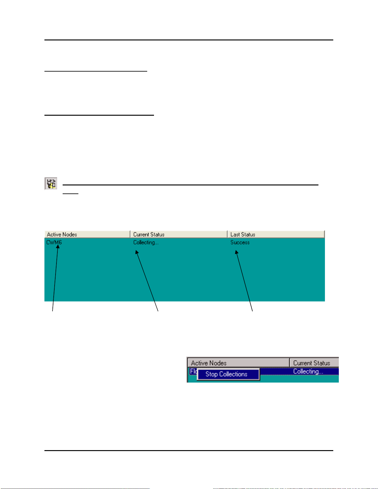
Viewing a List of the Controllers in which a Collection is Occurring Right Now
To view a list of the controllers to which a collection is underway, at this moment, click on the
'Active Nodes' icon, shown above, or click on ViewActive Collections.
List of the controllers for
which collections are
currently underway.
Status of the
collection that is
underway.
Status of the
previous collecton
from this controller.
If desired, you can stop the collection
underway, by right clicking on the node
name, and choosing "Stop Collections"
from the pop-up menu.
45 OpenBSI Harvester
Page 52

Monitoring the Status of Your Collections
Viewing a List of Controllers which are experiencing Communication Errors or other Failures
To view a list of the controllers which are experiencing communication errors or other errors on
one or more of their last scheduled collections, click on the 'Node Errors' icon, or click on View
Collection Errors.
This is a list of
the controllers
which are having
errors while
trying to collect
data.
This is the
current status
of collections
This is a list of the error
on the last collection
attempt
OpenBSI Harvester 46
Page 53

Monitoring the Status of Your Collections
Viewing a list of Debugging Messages
The Harvester reports various debugging messages which relate to how collections are
occurring, and what errors are encountered. These messages are primarily for use by Bristol
development and support personnel, however, they may be viewed by clicking on the 'Debug
Msgs' icon, shown above, or by clicking on View Debug Messages. NOTE: Only debugging
errors related to the currently selected controller will be displayed.
Placing a controller into Maintenance Mode
Maintenance Mode is a mode of operation in which communications with a controller (via radio,
etc.) are kept running, even when no collections are occurring. This may be useful during
maintenance or testing, or if other programs need access to the controller (e.g. DataView or an
HMI package) even though the Harvester is between collections.
To place a controller into Maintenance Mode, click on the icon for it, then click on the [Start
Maint] button.
To place a controller into Maintenance Mode, click on its
icon, then click on [Start Maint].
The Harvester will then send a message to turn ON the Maintenance Mode signal inside the
controller. (This signal triggers user defined logic in the control strategy which leaves
communications active.)
47 OpenBSI Harvester
Page 54

Monitoring the Status of Your Collections
Once Maintenance Mode has been successfully activated, the icon for the controller
placed into maintenance will be displayed with a yellow “M” over it, and the controller
will be added to the list of controllers in Maintenance Mode.
Viewing the List of Controllers Currently in Maintenance Mode
To view a list of the controllers currently in Maintenance Mode, click on the 'Maint. Mode' icon,
shown above, or click on ViewMaintenance Mode.
Controllers which
are currently in
Maintenance Mod e
Status of the
controller
Status of
last collection
Taking a Controller Out of Maintenance Mode
To remove a controller from Maintenance Mode, click on the icon for it, then click on the [Stop
Maint.] button.
OpenBSI Harvester 48
Page 55

Monitoring the Status of Your Collections
Turning on Polling for a Particular Controller
Polling is a term referring to a request for data sent by the OpenBSI communications system to
the controller network. Normally, polling from a particular controller would only be activated
when the Harvester is ready to perform a collection, according to a predefined schedule. For
example, in a radio system, polling of a particular controller would only occur when radio
communication is scheduled to be active with that controller; at all other times, polling of that
controller would be shut off.
The [Start Poll] button allows the user to force polling at other non-scheduled times (for
example, if communications with the controller need to be tested.) To do this, click on the icon
for the controller you want to poll, and click on the [Start Poll] button. Polling will begin. You
can shut off polling by clicking on the [Stop Poll] button.
Performing an 'On Demand' Collection
If you want the Harvester to collect data
from a controller at some time other than
when it is normally scheduled to perform a
collection, you can force an 'on demand'
collection.
To do this, click on the icon for the controller from which you want to collect data, and click on
the [Demand Coll] button. The On Demand dialog box will appear.
In the "Enter maximum number of records to collect" field, enter the maximum number of
records (i.e. array rows, archive rows, signals from a list) that you want to collect, then click on
[OK]. The Harvester will immediately attempt to perform collections from that controller.
Clearing Error, Status, and Timestamp Information using ‘Init Collection’
To clear (erase) the Error, Last Collection, and Timestamp information showing in the window
for a particular controller, click on the icon for that controller, then click on the [Init Collection]
button.
49 OpenBSI Harvester
Page 56

This page is intentionally left blank
Page 57

Appendix A - Writing File Data to Signals
Appendix A - Writing File Data to Signals
The Harvester's can optionally read ASCII text files containing signal values, and write those
signal values to corresponding signals in the node. This is useful for changing the value of
configuration signals in the node.
There are two different file formats supported - Write List Files (*.WLS) and Write Signal Files
(*.WSG).
During the collection of data for a particular node, the Harvester will check to see if a WLS or
WSG file exists for that node; if it does, the values in the file will be written to the node, during
the collection pass.
Write List File Format
The Write List File must be in an ASCII text format, and must be located in the Write Files
directory, as specified in the "Write File Directory" in the Harvester's System Information
dialog box. The file base name must be the node name, as defined in the NETDEF files, and the
file extension must be "WLS".
The format of the Write List File is presented below:
n number of list definitions in this Write List File
list definition 1
list definition 2
.
.
.
list definition n
the number of the signal list
the starting index into the list
x number of signals being written to
value 1
value 2
.
.
value x
Values in the definition must be consecutive. They can be analog values; or for logical signals,
either ON/OFF or TRUE/FALSE.
where a list definition consists of:
A-1 Open BSI Harvester
Page 58

Appendix A - Writing File Data to Signals
File Entry in RTU3.WLS Explanation
In the example shown, below, a Write List file has been created for the node called RTU3. Its
Write List File must therefore be named RTU3.WLS.
The first line of the RTU3.WLS file indicates that it contains 2 list definitions.
The first list definition applies to signal list 1 in RTU3, and will write to 2 consecutive list
entries, starting with the fifth entry in the list. It will write a value of 1.9 to the fifth entry in the
list 1, and a value of TRUE to the sixth entry in list 1.
The second list definition applies to signal list 27 in RTU3. It will write to 3 consecutive list
entries, starting with the eighth entry in the list. It will write a value of ON to the eighth entry of
list 27, a value of 1001 to the ninth entry of list 27, and a value of 45 to the tenth entry of list 27.
2 number of list definitions
1 list definition for signal list 1
5 start with 5th signal in signal list 1
2 write values to 2 consecutive signals, i.e. signal 5 and 6 in list1
1.9 signal 5 val ue
TRUE signal 6 val ue
27 list definition for signal list 27
8 start with 8th signal in signal list 27
3 write values to 3 consecutive signals, i.e. signals 8, 9, and 10
ON signal 8 val ue
1001 signal 9 val ue
45 signal 10 value
Write Signal File
A Write Signal File must be in an ASCII text format, and must be located in the Write Files
directory, as specified in the "Write File Directory" in the Harvester's System Information
dialog box. A Write Signal file must be named
where the file base name of node is the node name of the controller which will be written to, and
WSG is the file extension. This node name must exist in the NETDEF files. The first line of the
WSG file must be an integer specifying the number of signals in the file. Each of the remaining
lines of the file must consist of a signal name, and a signal value, separated by a space. Either
analog or logical signals may be used; string signals are not supported. If a logical signal is used,
its value must be either ON/OFF or TRUE/FALSE.
In the example shown, below, a Write Signal file has been created for the node called DPU5. Its
Write Signal file must therefore be named DPU5.WSG.
Open BSI Harvester A-2
node.WSG
Page 59

Appendix A - Writing File Data to Signals
3
VALVE01.OPEN.NOW TRUE
PUMP01.POWER.ON ON
SETPOINT.WATER.TEMP 32
Open BSI Harvester A-3
Page 60

This page is intentionally left blank
Page 61

Appendix B - File Naming Conventions
File Type
File Format
File Naming Convention
Example File Name
Archive
Binary
nnnnnnnn_Cxxx.yyy
RPC5_C001.000
Array
Binary
nnnnnnnn_Axxx.yyy
NORTHWD_A001.000
Audit
ASCII
nnnnnnnn_Exxx.yyy
FLOW3_E001.000
List
ASCII
nnnnnnnn_Lxxx.yyy
PARKROAD_L001.000
Appendix B - File Naming Conventions
The data collected from controllers by the Harvester is saved in data files at the OpenBSI
Workstation.
The directory where these files are saved is specified in the "Raw File Storage Directory" field
in the Harvester's System Information dialog box.
Once the files are saved, they are typically exported to OpenEnterprise, Microsoft® Excel, or
some other third-party package, using the OpenBSI Data File Conversion Utility, described in an
addendum to this manual.
A maximum of 999 files can be saved of a given type in the Raw File Storage Directory. Once
this number is exhausted, older files will be overwritten, as new data must be saved.
The table, below, details the file naming conventions:
Where:
nnnnnnnn = the controller's node name (as defined in the NETDEF files)
xxx = the structure number beginning with 001 (e.g. array number)
yyy = the file number ranging from 000 to 999
B-1 OpenBSI Harvester
Page 62

This page is intentionally left blank
Page 63

Appendix C - Sample ACCOL Task for Radio Control
Appendix C - Sample ACCOL Task for Radio Control
When using radios as the communication link between the Harvester and a Network 3000
controller, power consumption by the radio is normally an important consideration. Power may
be conserved by ensuring that under normal operating conditions, a controller's radio is ONLY
turned ON when it is scheduled to send/receive data from the Harvester. This is also important in
preventing interference between multiple controllers which share the same radio frequency.
The radio turn ON logic is based on a calculation involving a controller's local address, its
expanded node addressing group number, and other parameters defined both in the ACCOL load,
and in the Harvester.
The sample ACCOL task in this appendix represents one approach to creating such logic, and
should only be used as a guide. This sample task only shows the part of the ACCOL load related
to radio control; it does NOT cover other communication details such as buffers, port definitions,
etc. Questions regarding this task should be directed to Bristol's Application Support Group.
Task Description
Turn-ON Logic Highlights
This task assumes the Harvester has a scan interval of 1 hour (3,600 seconds).1 The time within
each hour that the controller will turn ON its radio is stored in the signals HOUR.MIN and
HOUR.SEC, and is calculated by the lines:
60 * CALCULATOR
10 :IF(#NODEADR!=127)
20 NODE.TIME=((#NODEADR-1)*26)+(GROUP.ADDR*5)+60
30 HOUR.MIN=:INT(NODE.TIME/60)
40 HOUR.SEC=NODE.TIME-(60*HOUR.MIN)
where in line 20, #NODEADR is a system signal representing the local address of this
controller, and GROUP.ADDR is a signal which holds the Expanded Node Addressing group
number (as defined during system configuration). The values "26", "5", and "60" are the poll
time per node, poll time per group, and start time offset, respectively, which must be identical to
the values for those parameters defined in the Harvester. Lines 30 and 40 of the Calculator
convert the turn ON time (in seconds) to minutes and seconds. The HOUR.MIN and HOUR.SEC
values are checked against #TIME system signals, later in the task, to determine when it is time
2
to turn on the radio:
160 :IF((#TIME.007==HOUR.SEC)&(#TIME.006==HOUR.MIN))
170 :IF(RADIO.HOUR.ENBL)
180 RADIO.HOUR.REQ=#ON
1
The start time of a scan interval is measured from midnight (00:00) of the current day.
2
As part of its communication activities, the Harvester regularly sends a Node Routing Table (NRT) to each
controller. This prevents a loss of time synchronization between the PC and controllers.
C-1 OpenBSI Harvester
Page 64

Appendix C - Sample ACCOL Task for Radio Control
190 :ENDIF
Later, after various checking is performed, the radio is actually activated using the Turn DTR
ON feature of the Portstatus module.
30 :C CHECK TO SEE IF REQUIRED TO BE ON
40 :IF(RADIO.ACTIVE)
50 MASTER.RADIO.MODE=5
60 :ENDIF
330 * PORTSTATUS
PORT MASTER.PORT.
MODE MASTER.RADIO.MODE
STATUS MASTER.RADIO.STAT
Modes of Operation
This ACCOL task supports 5 different modes of operation. Most of the modes also include userdefined setpoints which are fed into Timer Module logic to determine how long the radio stays
ON. Each mode is summarized, briefly, in the table below:
Local Turn ON Mode
Daily Turn ON Mode
Hourly Turn ON Mode
This mode is enabled by turning ON the signal
RADIO.LOCAL.ENBL. This mode allows the radio to be activated
manually by an operator using a keypad device. The signals
LOCAL.TIME.SP and LOCAL.TIMOUT.SP are used to define the
length of the ON time, and timeout periods for this mode.
This mode supports turning on the radio daily, and is enabled by
setting valid values on the DAY.HOUR, DAY.MIN and DAY.SEC
signals. These turn ON time values are checked against the
#TIME.005 (hours) #TIME.006 (minutes) and #TIME.007 (seconds)
system signals, respectively. The signals DAY.TIME.SP and
DAY.TIMOUT.SP are used to define the length of the ON time, and
timeout periods for this mode.
This mode is the normal method of communication with the Harvester,
as discussed, above, under Turn ON Logic Highlights. This mode is
enabled by turning ON the signal RADIO.HOUR.ENBL. The actual
turn ON time is defined in the signals HOUR.MIN and HOUR.SEC.
The signals HOUR.TIME.SP and HOUR.TIMOUT.SP define the
length of the ON time, and timeout periods for this mode. A daylight
hours mode option is also provided. This option is enabled by turning
ON the signal RADIO.DLIGHT.ENBL. When ON this mode limits
the Hourly Turn ON Mode to hours between the value of
RADIO.DLIGHT.STRT and RADIO.DLIGHT.END. If the time of
day in hours, as indicated on the system signal #TIME.005 is not
between those two values, Hourly Turn ON Mode will be disabled.
OpenBSI Harvester C-2
Page 65

Appendix C - Sample ACCOL Task for Radio Control
Maintenance Mode
Maintenance Mode allows a radio to be left ON for longer than the
normally scheduled time period. This may be useful during radio
maintenance or system debugging. This mode is enabled by the
operator, by turning ON the signal RADIO.MAINT.REQ. (This signal
must also be defined in the Harvester as the Maintenance Mode
Signal.) The signals MAINT.TIME.SP and MAINT.TIMOUT.SP
define the length of the ON time, and timeout periods for this mode.
Radio Turn OFF Mode
This mode allows the Harvester to notify the controller that it has
finished collecting data, and that the radio may be turned OFF. This is
part of normal Harvester communications, and is handled by the signal
RADIO.RESET.REQ. (This signal must also be defined in the
Harvester as the Communications OFF Signal.)
ACCOL Task Code
*TASK 6
10 * C@
THIS TASK IS TO CONTROL THE RADIO VIA THE DTR SIGNAL ON THE@
NETWORK PORT (PORT C).@
THE SIGNAL "RADIO.ACTIVE." CONTROLS THE PORT STATUS MODULE.@
THE SIGNAL "RADIO.TIMER.RSET" IS USED TO TURN OFF RADIO@
20 * C@
THE PORT IS CONTROLLED VIA A TIMER SO THAT IF THERE IS@
NO COMMUNICATION TO THE UNIT THE RADIO IS THEN TURNED OFF@
30 * C CHECK TO SEE IF TIME TO CALCULATE HOURLY AND DAILY ENABLE TIMES
40 * IF (NODE.CALC)
50 * C@
DETERMINE NODE OFFSET COLLECTION TIME:@
@
SECONDS PAST HOUR= ((NODE ADDR-1)*26)+(GROUP#*5)+OFFSET@
@
**** NOTE: GROUP.ADDR (GROUP#) MUST BE MANUALY CONFIGURED !!!@
60 * CALCULATOR
10 :IF(#NODEADR!=127)
20 NODE.TIME=((#NODEADR-1)*26)+(GROUP.ADDR*5)+60
30 HOUR.MIN=:INT(NODE.TIME/60)
40 HOUR.SEC=NODE.TIME-(60*HOUR.MIN)
50 DAY.MIN=HOUR.MIN
60 DAY.SEC=HOUR.SEC
70 NODE.CALC=#OFF
80 :ENDIF
70 * ENDIF
80 * C CHECK FOR TIMER TRIGGER SIGNAL IF ON THEN SKIP HOUR TESTS AND@
TURN OFF TRIGGER TO ALLOW FOR RE-TRIGGER OF TIMER
90 * IF (RADIO.TIMER.TRIG)
100 * CALCULATOR RADIO.TIMER.TRIG=#OFF
110 * ELSE
120 * C@
CHECK FOR TIME OF HOUR TURNON (WITH DAYLIGHT OPTION) SIGNALS:@
RADIO.DLIGHT.ENBL ON IF ACTIVE ONLY DURING DAYLIGHT HOURS@
HOUR.MIN MINUTE FOR HOURLY TURN ON@
HOUR.SEC SEC OF MIN FOR HOURLY TURNON@
RADIO.DLIGHT.STRT START HOUR OF DAY LIGHT@
RADIO.DLIGHT.END END HOUR OF DAY LIGHT@
OpenBSI Harvester C-3
Page 66

Appendix C - Sample ACCOL Task for Radio Control
RADIO.HOUR.ENBL ENABLE SIGNAL FOR HOURLY TURN ON
130 * CALCULATOR
10 :C CHECK TO SEE IF TIME OF DAY ENABLE
20 :IF(RADIO.DLIGHT.ENBL)
30 :C IF DAYLIGHT, THEN CHECK TIME OF DAY FOR ENABLE OF HOURLY COMM.
40 :IF((#TIME.005>RADIO.DLIGHT.STRT)&(#TIME.005<RADIO.DLIGHT.END))
50 RADIO.DLIGHT.OK=#ON
60 :ELSE
70 RADIO.DLIGHT.OK=#OFF
80 :ENDIF
90 :ELSE
100 :C DAY LIGHT NOT ENABLED, THEREFORE ALWAYS OK!
110 RADIO.DLIGHT.OK=#ON
120 :ENDIF
130 :C DAYLIGHT TEST DONE, CHECK FOR HOURLY TURN ON
140 :IF(RADIO.DLIGHT.OK)
150 :C CHECK IF MIN AND SECOND = START RADIO
160 :IF((#TIME.007==HOUR.SEC)&(#TIME.006==HOUR.MIN))
170 :IF(RADIO.HOUR.ENBL)
180 RADIO.HOUR.REQ=#ON
190 :ENDIF
200 :ELSE
210 RADIO.HOUR.REQ=#OFF
220 :ENDIF
230 :ENDIF
140 * C CHECK TO SEE IF TIME FOR DAY (ONCE PER DAY) AS DEFINED BY:@
DAY.HOUR@
DAY.MIN@
DAY.SEC
150 * CALCULATOR
10 :C CHECK TO SEE IF TIME TO TURN ON ONCE PER DAY COMMAND
20 :C TO ELIMINATE DAILY POLL .. MAKE DAY.HOUR > 24
30 :IF((#TIME.007==DAY.SEC)&(#TIME.006==DAY.MIN)&(#TIME.005==DAY.HOUR))
40 RADIO.DAY.REQ=#ON
50 :ELSE
60 RADIO.DAY.REQ=#OFF
70 :ENDIF
160 * C CHECK TO SEE IF LOCAL USER@
@
RADIO.LOCAL.ENBL MUST BE ON FOR LOCAL SELECTION@
170 * CALCULATOR
10 :C CHECK FOR KEYPAD SENSE OF OPERATOR
20 :IF(RADIO.LOCAL.ENBL)
30 :IF(KEYPAD.STATE)
40 :C KEYPAD SENSOR ON, TURN ON LOCAL REQUEST, TURN OFF KEYPAD
50 RADIO.LOCAL.REQ=#ON
60 KEYPAD.STATE=#OFF
70 :ENDIF
80 :ENDIF
180 * C RADIO COMMANDED ON CHECK TIMEOUT
190 * C CHECK # OF DATA REQUESTS
200 * PORTSTATUS
PORT MASTER.PORT.
MODE STATUS.MODE.
LIST COMMSTAT.LIST.
210 * C DETERMINE WHAT SETPOINT TO USE
220 * CALCULATOR
10 :C CHECK FOR POLLS FROM THE MASTER ( IS COMM. ESTABLISHED)
20 COMMSTAT.TRIG=(COMMSTAT.POLL!=COMMSTAT.POLL.LAST)|(COMMSTAT.RX!=@
COMMSTAT.RX.LAST)|(RADIO.LOCAL.REQ|RADIO.MAINT.REQ|RADIO.DAY.REQ|@
RADIO.HOUR.REQ)
30 COMMSTAT.POLL.LAST=COMMSTAT.POLL
40 COMMSTAT.RX.LAST=COMMSTAT.RX
OpenBSI Harvester C-4
Page 67

Appendix C - Sample ACCOL Task for Radio Control
50 :C CHECK FOR TURN ON REQUEST BY PRIORITY
60 :IF(RADIO.LOCAL.REQ)
70 RADIO.TIME.SP=LOCAL.TIME.SP
80 RADIO.TIMOUT.SP=LOCAL.TIMOUT.SP
90 RADIO.TIMER.TRIG=#ON
100 RADIO.TIMER.RSET=#ON
110 RADIO.LOCAL.REQ=#OFF
120 :ELSEIF(RADIO.MAINT.REQ)
130 RADIO.TIME.SP=MAINT.TIME.SP
140 RADIO.TIMOUT.SP=MAINT.TIMOUT.SP
150 RADIO.TIMER.TRIG=#ON
160 RADIO.TIMER.RSET=#ON
170 RADIO.MAINT.REQ=#OFF
180 :ELSEIF(RADIO.DAY.REQ)
190 RADIO.TIME.SP=DAY.TIME.SP
200 RADIO.TIMOUT.SP=DAY.TIMOUT.SP
210 RADIO.TIMER.TRIG=#ON
220 RADIO.TIMER.RSET=#ON
230 RADIO.DAY.REQ=#OFF
240 :ELSEIF(RADIO.HOUR.REQ)
250 RADIO.TIME.SP=HOUR.TIME.SP
260 RADIO.TIMOUT.SP=HOUR.TIMOUT.SP
270 RADIO.TIMER.TRIG=#ON
280 RADIO.TIMER.RSET=#ON
290 RADIO.HOUR.REQ=#OFF
300 :ENDIF
230 * ENDIF
240 * C END OF "RADIO.TIMER.TRIG" TEST
250 * C@
CHECK RADIO RESET REQUEST FROM HOST@
IF REQUESTED, THEN WAIT FOR ~ 1.5 SECONDS TO ALLOW@
COMMUNICATIONS TO COMPLETE BETWEEN MASTER AND REMOTE
260 * CALCULATOR
10 :C CHECK FOR RESET REQUEST
20 :IF(RADIO.RESET.REQ)
30 :C IF RESET REQUEST THEN INCREMENT LOOP COUNTER
40 RADIO.RESET.CNT=RADIO.RESET.CNT+1
50 :C IF COUNTER =3 (1.5 SECONDS AFTER SHUTOFF) THEN RESET TIMERS
@
THIS IS NEEDED TO ALLOW THE REMOTE TO RESPOND TO THE TURN
OFF@
COMMAND.
60 :IF(RADIO.RESET.CNT>=3)
70 RADIO.RESET.CNT=0
80 RADIO.RESET.REQ=#OFF
90 RADIO.TIMER.RSET=#OFF
100 :ENDIF
110 :ELSE
120 RADIO.RESET.CNT=0
130 :ENDIF
270 * C RETRIGGER COMM TIMER
280 * TIMER
INPUT COMMSTAT.TRIG.
SETPOINT RADIO.TIMOUT.SP
RESET RADIO.TIMER.RSET
TIME COMMSTAT.TIME.
OUTPUT_1 RADIO.TIMER.RSET
290 * C IF NO POLLS IN TIME OUT PERIOD THEN RESET BOTH TIMERS AND@
TURN OFF PORT
300 * TIMER
INPUT RADIO.TIMER.TRIG
SETPOINT RADIO.TIME.SP
RESET RADIO.TIMER.RSET
OpenBSI Harvester C-5
Page 68

Appendix C - Sample ACCOL Task for Radio Control
TIME RADIO.TIME.REM
OUTPUT_1 RADIO.ACTIVE.
310 * C UPDATE STATUS OF RADIO CONTROL OUTPUT
320 * CALCULATOR
10 :C SET MODE COMMAND STATE FOR RADIO OFF
20 MASTER.RADIO.MODE=6
30 :C CHECK TO SEE IF REQUIRED TO BE ON
40 :IF(RADIO.ACTIVE)
50 MASTER.RADIO.MODE=5
60 :ENDIF
330 * PORTSTATUS
PORT MASTER.PORT.
MODE MASTER.RADIO.MODE
STATUS MASTER.RADIO.STAT
OpenBSI Harvester C-6
Page 69

Appendix D - Harvester Database Tables
Field Name
Data Type
Description
Version
Number
Version of the Harvester Database. This controls updates to
tables on new releases.
Scan
Interval
Number
User configured scan interval, in seconds.
Stagger
Nodes
Number
When in stagger mode, the number of nodes to skip.
Stagger
Force
Number
When this number of nodes is active, Stagger Mode is
activated.
Turn on
Delay
Number
The number of seconds to delay after the calculated ON time.
Start Time
Offset
Number
Offset (in seconds) into the Scan Interval when polling should
start.
Node Poll
Time
Number
The time required (in seconds) to collect data from a node.
Group Poll
Time
Number
The Offset (in seconds) to separate EBSAP groups throughout
the interval.
File Storage
Text
The directory path in which the Harvester will store data files
collected from the nodes.
Write Path
Text
The directory path where the Harvester will look for WLS and
WSG files.
Dial Retries
Number
The number of times the Harvester will retry dial nodes when
the line is busy.
Dial Wait
Number
The number of seconds between dial retries..
Add RTU
Yes/No
When this field is set to YES by an external program, the
HARV_ADD.INI file. This field is checked every 5 seconds.
Appendix D - Harvest er Database T ables
The Harvester uses several database tables for storing configuration information. These tables
can optionally be read from / written to by third-party applications specifically written for this
purpose.
System Information Table
The System Information Table contains information about the overall configuration of the
Harvester, calculation parameters for the scan interval, and directory paths.
Harvester will look for new RTUs to add in the
D-1 OpenBSI Harvester
Page 70

Appendix D - Harvester Database Tables
Field Name
Data Type
Description
Node Identifier
Text
User defined text to describe this node.
Disable
Yes/No
If set, no collection is performed.
On Demand
Yes/No
If set, data from the node is collected
simply by setting this database field to Yes.
On Demand List
Yes/No
If set, lists from the node are collected
that simply by setting this database field to Yes.
OnUserTimeChange
Yes/No
If set, the User Times have been changed
simply by setting OnUserTimeChange to Yes.
Turn Off Polling
Yes/No
If set, polling to this unit is stopped, and the
have been completed.
Scan Type
Number
The method of collection:
2 = User entered ON times
Interval
Number
If User entered interval, this field contains the
interval value.
Interval Units
Text
If User entered interval, this field contains the
user selected units.
Interval Offset
Number
Number of seconds to offset collections from
the inerval
Comm Off Sig
Text
This signal is set in the node to turn off
communications at the node end.
Maint Sig
Text
This signal is set in the node to start Maint.
Mode.
Collect Audit Sig
Text
If the signal is within an Audit record, all lists
for the node are collected.
Field Table
The field table contains information on the configuration of a controller.
immediately. NOTE: Harvester regularly
monitors this table entry for changes. Therefore,
if you want to have an external program trigger
an on-demand collection, you can do that
immediately. NOTE: Harvester regularly
monitors this table entry for changes. Therefore,
if you want to have an external program trigger
an on-demand collection of list data, you can do
externally. NOTE: Harvester regularly monitors
this table entry for changes. Therefore, you
could have an external program change the user
on times (User Time 1 through User Time 10,
later in this table) and activate the new on times
modem will be hung up after the collections
0 = Scan Interval
1 = User entered Interval
OpenBSI Harvester D-2
Page 71

Appendix D - Harvester Database Tables
Field Name
Data Type
Description
Skip History
Yes/No
If set Archive, Array, and Audit collections are
skipped on the first collection pass.
Username
Text
ControlWave nodes require a username and
Encrypted.
Password
Text
Password must be correct for the Username
entered above. Encrypted.
Start Collection Date
Date/Time
If set, indicates from what Date/Time to start
collecting Archive and/or Array data.
Avg On Time
Number
Average time in seconds the node is online and
collecting.
Num On Times
Number
The number of times data has been collected
from this node.
Last On Time
Date/Time
The last time data was collected from the node.
Total On Time
Number
The total time in seconds the node has been on
line.
Modem Request Sig
Text
Signal in node's master that turns on modem to
target node.
Modem Confirm Sig
Text
Signal in node's master that confirms node is
online.
Modem Retries
Number
The number of times the modem connection
will be attempted.
Modem Wait
Number
The number of seconds to wait before checking
the Modem Confirm signal.
User Time 1
Date/Time
User Configured On Time 1
User Time 2
Date/Time
User Configured On Time 2
User Time 3
Date/Time
User Configured On Time 3
User Time 4
Date/Time
User Configured On Time 4
User Time 5
Date/Time
User Configured On Time 5
User Time 6
Date/Time
User Configured On Time 6
User Time 7
Date/Time
User Configured On Time 7
User Time 8
Date/Time
User Configured On Time 8
User Time 9
Date/Time
User Configured On Time 9
User Time 10
Date/Time
User Configured On Time 10
password be supplied for collections to occur.
OpenBSI Harvester D-3
Page 72

Appendix D - Harvester Database Tables
Field Name
Data Type
Description
Node
Text
Target Node Name
Type
Text
Type of Collection
Item
Number
Node structure number (e.g.
list 10)
Disable
Yes/No
If set, this collection is
disabled.
Last Timestamp
Date/Time
Last valid timestamp collected
and Raw Arrays)
Last Error
Text
Error encountered on the last
collection pass.
Max Retries
Number
Maximum number of Retries
'failed'.
Common List
Number
Number of the Common
node)
Reset Audit
Yes/No
If set, the Audit records
Audit buffer in the node.
Max Rows
Number
Max number of archive rows
to collect per pass.
Push Rows
Number
Number of array rows to
the Pushdown Array scheme.
Mult Arrays
Number
Number of Arrays in the Wrap
Multiple Array scheme.
Last Row
Number
The last sequence number or
array row collected.
Last Array
Number
For Multiple wrap collections,
this is the last array collected.
Crop Table
The crop table contains information about what type of data will be collected from the controller.
(for Archives and Arrays) or
last time structure was
collected (for Lists, Audits,
before marking a collection as
Signal Name List to associate
with this list (if zero signal
names are collected from the
collected are removed in the
collect in the first message, in
OpenBSI Harvester D-4
Page 73

Appendix D - Harvester Database Tables
Field Name
Data Type
Description
List
Number
Common List Number 1
Entries
Number
Number of signals in List 1
List
Number
Common List Number 2
Entries
Number
Number of signals in List 2
: : :
List
Number
Common List Number n
Entries
Number
Number of signals in list n
List
Entries
10
8
20 2 43
7
Field Name
Data Type
Description
List Number
Number
Common List Number
Signal
Text
Signal Name
List Number
Signal
1
STATION.FLOW.
1
STATION.PRES.
1
STATION.TEMP.
Common List Tables
The Common List Tables contain signal names for signal lists in the controllers. The user can
configure these to eliminate the communications overhead of collecting the signal names. The
first table (common lists table) shows the number of the list, then the number of entries in the
list. The second table (common list signals table) contains all of the signal names for all of the
common lists.
Common Lists Table
For example, if there are three common lists numbered 10, 20, and 42, and they have 8, 2, and 7
signals in them, respectively, then the Common Lists Table would appear as follows:
Common List Signals Table
For the Common List Signals Table, the table must include a list number (identifying which
Common List a signal belongs to) and the signal name of each signal.
For example, if you have two common lists (numbered 1 and 2) each with four and three signals
in them, respectively, the Common List Signals Table would appear similar to that shown below:
OpenBSI Harvester D-5
Page 74

Appendix D - Harvester Database Tables
List Number
Signal
1
STATION.ACTIVE.
2
DAILY.FLOW.AVG
2
DAILY.TEMP.AVG
2
DAILY.PRES.AVG
OpenBSI Harvester D-6
Page 75

Appendix E – HARVESTER Initialization Files
Appendix E – HARVESTER Initia l ization Files
HARVESTER.INI
The HARVESTER.INI file, which is located in the \WINDOWS folder, sets certain
defaults for how the Harvester operates. The format of the HARVESTER.INI file is
as follows:
[TIMERS]
CONFIGVIEW_TIMER=config_time
MONVIEW_TIMER=monitor_time
RTUVIEW_TIMER=rtu_time
ONDEMAND_TIMER=demand_time
STATION=station
BROADCAST=broadcast
CRITICAL=critical
SILENTEXIT=silent
[DEBUG]
ENABLE=enable
[DISTRIBUTE]
INTERVAL=interval
STARTTIME1=time1
STARTTIME2=time2
STARTTIME3=time3
STARTTIME4=time4
where: config_time is the rate (in milliseconds) at which the
configuration pane on the right hand top of the
window is updated.
monitor_time is the default rate (in milliseconds) at which the
monitor pane of the window is updated.
rtu_time is the default rate (in milliseconds) at which the
tree of RTUs pane of the window is updated.
demand_time is the default rate (in milliseconds) at which the
Harvester will check for an on-demand request for
data.
station when set to ‘1’ will write RTU configuration data to
the station file.
E-1 OpenBSI Harvester
Page 76

Appendix E – Harvester Initialization Files
broadcast if set to ‘1’, broadcasts a message at the start and
end of a collection.
critical while the Harvester is normally considered to be a
critical message exchange (mex), thereby
preventing OpenBSI from being shut down. When
this is set to ‘0’, however, Harvester is not
considered critical, and so OpenBSI can be shut
down.
silent when set to ‘1’, will allow the Harvester to be closed
without a confirmation prompt. In addition, when
set to ‘1’, Harvester startup will be in a minimized
state.
enable set to ‘1’ to activate debug mode, or ‘0’ to turn off
debug mode. In Debug mode, the contents of the
monitor window is written to the file harv_log.txt
in the \ProgramData\Bristol\OPENBSI directory.
interval is the default interval used with the distributed on
times.
time1,time2, time3,
time4 are a set of four base times during the day from
which the interval will be added to calculate the
collection times for RTUs. Times should be
specified as hours and minutes in 24 hour format:
hh:mm.
OpenBSI Harvester E-2
Page 77

Appendix E – Harvester Initialization Files
HARV_ADD.INI
The HARV_ADD.INI file allows one or more RTU definitions to be added or
removed from OpenBSI, and Harvester collections to be configured for RTUs.
OpenBSI periodically checks the \ProgramData\Bristol\OPENBSI installation
directory to see whether a HARV_ADD.INI file has been added, and if it has,
dynamically re-configures the system based on the entries in the file. Once this
configuration is completed the HARV_ADD.INI file is automatically deleted so the
configuration does not get repeated.
This allows a user, or some external program, to change the system configuration
using a batch file, instead of using the dialog boxes of the standard graphical user
interface.
If a failure occurs during the parsing of the HARV_ADD.INI file, it will be renamed
to HARV_ADD.ERR, and the configuration changes will not be processed.
Multiple RTU definitions may exist in the same file.
[RTU_x]
Name=rtu_name
Delete=delete
Node_ID=description
Write_Station=station_file
Default_Config=default_RTU_config
Disable=disable_collections
Skip_Hist=skip
Turn_Off_Poll=no_poll
Comm_Off_Signal=comm_off_sig
Maint_Mode_Signal=maint_mode_sig
Force_List_Signal=force_list_sig
Modem_Req_Signal=modem_req_sig
Modem_Confirm_Signal=modem_confirm_sig
Modem_Retries=retries
Modem_Wait=wait_time
Scan_Type=scantype
Interval=interval
Interval_Units=interval_units
Interval_Offset=interval_offset
Start_Coll_Date=start_date
User_Time_1=user_time1
OpenBSI Harvester E-3
Page 78

Appendix E – Harvester Initialization Files
User_Time_2=user_time2
:
User_Time_10=user_time10
Collection1=coll_1
Collection2=coll_2
:
Collectionn=coll_n
Network=network_name
RTUType=type
Local_Addr=local_address
Prim_IP=aaa.bbb.ccc.ddd
Pred=node
Sec_IP=eee.fff.ggg.hhh
MsgTmo=timeout
Load=filename
Dial=dial_string
WebPage=startup_page
AlarmDest1=aaa.bbb.ccc.ddd
AlarmDest2=eee.fff.ggg.hhh
AlarmDest3=iii.jjj.kkk.lll
AlarmDest4=mmm.nnn.ooo
RBEDest1=aaa.bbb.ccc.ddd
RBEDest2=eee.fff.ggg.hhh
RBEDest3=iii.jjj.kkk.lll
RBEDest4=mmm.nnn.ooo.ppp
FailType=ip_fail_choice
TS_Disable=toggle
Comm_Direct=proxydirect
[Coll_n]
Type=collection_type
Item=item_num
Disable=disable
View_Timestamp=show_timestamp
Max_Retry=num_attempts
Max_Rows=max_rows
Collect_All=max_coll
Audit_Reset=delete_records
Push_First=number
Common_List=list_number
Wrap_Number=num_arrays
OpenBSI Harvester E-4
Page 79

Appendix E – Harvester Initialization Files
where:
[RTU_x] x is an integer referring to which RTU definition is
being added or deleted. For the first RTU
definition in the file, x would be 1, for the second
definition in the file, it would be 2, etc.
Name=rtu_name rtu_name is the name of the RTU being added to
or deleted from the system via this definition.
rtu_name must either match the name of an RTU
already configured in NetView, or the RTU must
be added to NetView using the ‘Network’ keyword
further on in this definition.
Delete=delete if delete is set to ‘1’, this RTU will be deleted from
the Harvester.
Node_ID=description Enter a textual description of the node that will
appear in the Harvester "Node Information"
window. Only the first 64 characters you enter will
be displayed as the description.
Write_Station=toggle if toggle is set to 0, information from the RTU
definition will NOT be written to the station file. If
set to 1 (default), it will be written to the station
file. If set to 1 and no station file exists, it will be
created.
NOTE: If there are multiple list, arrays, etc. being
collected from this controller, only the first one
will be used to update the station file.
Default_Config =
default_RTU_config
Disable=disable_collections If disable_collections is set to 1, collections for this
Skip_Hist=skip
If specified, the Harvester will use the defaults for
the RTU named in default_RTU_config for this
RTU’s configuration. NOTE: If a
default_RTU_config is specified, the remaining
entries for this RTU are not necessary, as they
will assume the defaults of the RTU specified by
default_RTU_config.
RTU are disabled. If set to 0 (default) collections
remain active. This would typically be used only if
a controller has been temporarily taken out of
service for repairs, or if there are communication
problems which must be fixed prior to attempting
collections.
If skip is set to 1, collection of array/archive data
for this RTU is disabled during the first collection
OpenBSI Harvester E-5
Page 80

Appendix E – Harvester Initialization Files
pass, and instead it will wait for the next
calculated interval. If set to 0 (default) the
Harvester will attempt to collect historical data
during the first collection pass.
Turn_Off_Poll=no_poll
Comm_Off_Signal=
comm_off_sig
Maint_Mode_Signal=
maint_mode_sig
Force_List_Signal=
force_list_sig
Modem_Req_Signal=
modem_req_sig
Modem_Confirm_Signal= If the Harvester is collecting data from a slave
If communications with a particular controller are
via a dial-up modem or radio, as soon as the
Harvester completes its collections, it may be
desirable to turn polling off, because there is no
reason to continue requesting data. If the
controller has a direct cable connection (i.e. it is
always connected) it may make sense to continue
polling.
If no_poll is set to ‘1’, polling will cease after a
collection is completed. If set to ‘0’ (default) polling
continues after a collection is completed.
comm_off_sig is a signal that the Harvester will
turn ON in the RTU when collection is complete.
This may be used to trigger user-defined logic in
the RTU to turn off a radio.
maint_mode_sig is a signal in the RTU. If set ON
(True), by the Harvester, it is intended to trigger
user-configured logic that keeps communications
active with the RTU, even though no collections
are occurring, so that maintenance /
communications testing/ debugging can be
performed.
This signal is set ON by user-defined logic in the
program as a notification to the Harvester that the
configuration list has changed, somehow, and so it
should be re-collected by the Harvester. This
signal MUST be designated for audit trail
collection via the EAudit Module or AUDIT
function block.
If the Harvester is collecting data from a slave
controller which communicates to its master
controller in the network via a dial-up modem, the
signal identified by modem_req_sig is turned ON
by the Harvester as a trigger to execute userdefined logic in the Master controller that will
cause it that will cause it to dial-up its slave
controller.
OpenBSI Harvester E-6
Page 81

Appendix E – Harvester Initialization Files
modem_confirm_sig
Modem_Retries=retries
Modem_Wait=wait_time
Scan_Type=scantype
Interval=interval
Interval_Units=interval_units This defines the units of the interval. The possible
Interval_Offset=interval_offset This specifies a period of time in seconds (0 to
controller which communicates to its master
controller in the network via a dial-up modem, the
signal identified by modem_confirm_sig must be
turned ON by user-defined logic in the Master
controller as a confirmation to the Harvester that
the Slave node has been successfully dialed, and
collections can commence.
After setting the modem_req_sig to ON, this is the
number of times the Harvester will check to see
that the modem_confirm_sig has been turned ON.
This number can range from 0 to 5. The default is
1,
After setting the modem_req_sig, this is the length
of time (in seconds) the Harvester will wait before
checking to see that the modem_confirm_sig has
been turned ON. This same period applies to all
"Modem_Retries" as well. (This can range from 1
to 5.) The default is 1.
Specifies how data scanning is performed. Choose
from the following: 0=Scan Interval (default),
1=User Interval, 2=User On Times
This applies when scantype is either 1 or 2 (scan
interval) or (user interval). The interval is a period
of time that may range from 1 to 3600. The units
of time are specified by Interval_Units. The
default is 1.
When used as the scan interval, the Harvester
attempts to communicate with a particular node
based on its location in the network, as
determined by an address calculation.
When used as a user interval, the Harvester
attempts to communicate with a particular node
every time a particular period of time has expired,
for example, every hour. For example, if the
interval is set to 1, and interval_units is set to
’hours’, then collections will occur every hour.
choices are ’minutes’,’hours’ or ’days’.
86400) measured from the beginning of the
interval, that the Harvester will wait before
OpenBSI Harvester E-7
Page 82

Appendix E – Harvester Initialization Files
Start_Coll_Date=start_date
User_Time_1= user_time1
User_Time_2= user_time2
:
User_Time_10= user_time10
Collection1=coll_1
Collection2=coll_2
:
Collectionn=coll_n
Network=network_name
RTUType=type
beginning its collection. This is often necessary if
arrays or archives are being updated in the
controller every hour, and it is necessary to wait
this number of seconds for the array / archive
manipulation to be completed. If left at the default
of 0, the collection will begin at the very start of
the interval. The offset can also be used to space
out collections, if several collections from multiple
controllers are scheduled to occur within the same
interval.
start_date specifies from which date in the
historical system, data collection should start. It
should be expressed in the format mm/dd/yyyy
where mm=months, dd=days, and yyyy=years.
When this is chosen, the Harvester attempts to
communicate with a particular node at up to ten
user-specified times during the day. user_time
must be specified as hh:mm:ss PM or hh:mm:ss
AM, depending upon whether the time is before or
after 12 noon.
These identify the names of collections for this
particular RTU. Parameters for the collections will
be defined in a section of the file with this name.
If this field is included in the [RTU_x] group,
Harvester will add this RTU to OpenBSI before
adding it to its own database. A check for RTUs
being added to the system is performed every 5
seconds. The network must already exist in
OpenBSI.
Several additional fields (RTUType, LocalAddr,
Prim_IP, Pred, Sec_IP, MsgTmo, Load, Dial,
WebPage, AlarmDest, RBEDest, FailType,
TS_Disable, Comm_Direct) are used to define the
RTU (some are required, some are optional).
type defines the type of RTU being defined.
Possible types are as follows:
Type: RTU:
1 RTU 3305
2 GFC 3308
3 RTU 3310
OpenBSI Harvester E-8
Page 83

Appendix E – Harvester Initialization Files
4 DPC 3330
5 DPC 3335
6 3508 TeleTrans
7 3530-series TeleFlow / TeleRTU /
TeleRecorder
9 ControlWave
10 ControlWave LP
12 ControlWave MICRO
13 ControlWave EFM
14 ControlWave GFC
15 ControlWave XFC
16 CW_10
17 CW_30
19 ControlWave Express
Local_Addr=local_address This is the BSAP local address (1 to 127).
Prim_IP=aaa.bbb.ccc.ddd
Pred=node
Sec_IP= eee.fff.ggg.hhh
MsgTmo=timeout
Load=filename
Dial=dial_string
WebPage=startup_page
AlarmDest1=aaa.bbb.ccc.ddd
AlarmDest2=eee.fff.ggg.hhh
AlarmDest3=iii.jjj.kkk.lll
AlarmDest4=mmm.nnn.ooo
RBEDest1=aaa.bbb.ccc.ddd
RBEDest2=eee.fff.ggg.hhh
RBEDest3=iii.jjj.kkk.lll
RBEDest4=mmm.nnn.ooo
FailType=ip_fail_choice
Prim_IP=aaa.bbb.ccc.ddd - If this is an IP node,
you must define a primary IP address.
Pred=node For BSAP networks, this would be the
predecessor RTU. If this is the first level of the
BSAP network, then specify the NHP name.
(Required)
Sec_IP=eee.fff.ggg.hhh - If this is an IP node, you
may optionally define a secondary IP address. The
default is 0.
This is the message timeout in seconds. The
default is 45.
filename is the name of the control strategy
running in the RTU (either an ACCOL load, or a
ControlWave project.)
The phone number this RTU will dial if
communication is via a dial-up modem.
The initial web page that will be displayed for this
RTU. Default: blank
Each RTU can send alarm messages to up to 4
different IP addresses. These are defined as alarm
destinations. The default is 0.
Each RTU can send RBE messages to up to 4
different IP addresses. These are defined as RBE
destinations. The default for these is 0.
Specifies what happens if IP communications fail.
There are two choices.
OpenBSI Harvester E-9
Page 84

Appendix E – Harvester Initialization Files
type=‘0’ Always try to establish Primary link.'
If you choose this option, OpenBSI will always
attempt to communicate with this RTU using the
Primary link (Primary IP Address), unless that link
fails, in which case, it will try to communicate using
the Secondary link (Secondary IP Address).
type=’1’ 'Stay with link that is working.
(Symmetric)' If you choose this option, OpenBSI
will attempt to use the current working
communication link (either Primary or Secondary)
and then if that link fails, fail-over to the alternate
link.
TS_Disable=toggle
Comm_Direct=proxydirect
[coll_n]
Type=collection_type
Item=item_num
Disable=disable
View_Timestamp= Can be set to display the most recently collected
Determines whether or not timestamps will be sent
to this RTU.
‘0’ TimeSync Enabled - If you choose this option,
time synchronization messages will NOT be
sent to this RTU. (Default)
‘1’ TimeSync Enabled' If you choose this option,
time synchronization messages will be sent to
this RTU.
Determines whether proxy direct access is allowed
to this IP RTU. 0 = Proxy direct access disabled
(default). 1 = Proxy direct access enabled.
The name of a collection section, as specified in the
[RTU] section. The same collection section can be
used by multiple RTUs if they share the same
collection parameters.
This indicates the kind of data being collected.
There are seven collection types: (Archive, Audit,
PushdownArray, RawArray, SignalList,
WrapArray, WrapMultipleArray)
This is the number of the structure being
collected, i.e. the array number, the archive
number, or the signal list number. If multiple
arrays are collected, this would be the number of
the first array in the group of consecutively
numbered arrays. This field does not apply to
Audit.
Specifies whether this collection is disabled:
0=collect (default), 1=disable collection
OpenBSI Harvester E-10
Page 85

Appendix E – Harvester Initialization Files
show_timestamp
Max_Retry=num_attempts
Max_Rows=max_rows
Collect_All=max_coll
Audit_Reset=delete_records
Push_First=number
Common_List=list_number
Wrap_Number=num_arrays If using Wrap Multiple arrays, this is the number
timestamp ("Last Timestamp") from this
controller, in the tree of nodes on the left hand
side of the main Harvester window. NOTE: Even
if there are multiple collections for a controller,
only one collection timestamp will be displayed.
Choices are:
0=timestamp not displayed (default)
1 =last timestamp displayed
This specifies the total number of attempts the
Harvester will make to collect data from this
controller on a given collection pass. A retry occurs
if there is a communication timeout. This can
range from 0 to 10. The default is 1.
This specifies the maximum number of array rows
which the Harvester will attempt to collect from
the controller on a given collection pass. This can
range from 1 to 99999. The default is 24.
Determines whether the Harvester will try to
collect only some rows, or the maximum number of
rows.
0=Normal collection (default)
1=Collect all using Max_Rows as max per message
Specifies whether audit records that have been
collected by the Harvester, will be deleted from the
controller.
0 = Don’t delete audit records in the RTU.
(default)
1 = Delete audit records in the RTU that have
already been collected.
This is the number of pushdown array rows to
collect during the first collection pass. This should
be set to match the number of rows of data
generated within the controller, that need to be
collected on a given collection pass. number can be
either 0 or 1 (default).
If using a Common List, list_number is the
number of that signal list. This can range from 1
(default) to 99999. If 0, collection occurs via signal
names.
of arrays used. This can range from 1 (default) to
99999.
OpenBSI Harvester E-11
Page 86

This page is intentionally left blank
Page 87

Appendix F - Harvester Error Messages
Error Message
Cause / Possible Remedy
Error - Archive File Not Found
The specified archive file could not be collected
in the ARCHIVE function block.
Error - Array Not Found
The specified data array could not be collected
than actually exists.
Error - Audit Buffer Not Found
The Audit data could not be collected because it
system properly in the RTU. In ACCOL II,
Appendix F - Harvester Error Messages
A list of common Harvester error messages, and their explanations, is included, below:
because it did not exist in the RTU.
• Verify that you did configure an Archive file
in the ACCOL load or ControlWave project
with that number.
• Check to see that you specified the correct
archive file number in the “Item Number”
field of the Collection Configuration dialog
box. For ACCOL II users, this number must
match the value on the ARCHIVE terminal
of the ARC_STORE module; for
ControlWave users; this number must match
the value on the iiArchiveNumber parameter
because it did not exist in the RTU.
• Verify that you did configure an array with
that array number in the ACCOL load or
ControlWave project. For ControlWave
users, make sure you have registered the
array using the REG_ARRAY function
block.
• Check to see that you specified the correct
array number in the “Item N u mber” field of
the Collection Configuration dialog box.
• If using Wrap Multiple Array collection,
verify that you did not specify too large a
value for the “Number of Multiple Arrays”
parameter in the Collection Configuration
dialog box, as this could cause the Harvester
to attempt to read a higher numbered array
F-1 OpenBSI Harvester
did not exist in the RTU.
• Verify that you did in fact set up the Audit
Page 88

Appendix F - Harvester Error Messages
Error Message
Cause / Possible Remedy
this would involve configuring the EAUDIT
Error - Collections Stopped
A collection has been stopped by the user by
collection.
Error - Common List Read
A problem occurred while trying to read the
check box marked.
Error - Comm Send Failure
The Harvester could not communicate with the
communicating.
Error - Comm Timeout
The RTU did not respond within the expected
too short.
Error - Crop Write Failure
Failure to update field with new timestamp.
Error - Dial Comm Line Busy
The phone line used for dial-up is already is use.
Module, and allocating sufficient memory
for the Audit entries. In ControlWave, this
would involve configuring the AUDIT
function block.
clicking on the “Stop Collections” pop-up
menu selection, thereby aborting the current
Common List in the RTU.
• Verify that a list with the number specified
in the Common List Configuration dialog
box actually exists in the RTU, and that the
names of the signals in that list match the
ones defined in the Common List
Configuration dialog box, and that they are
in the correct order.
• Verify that all the signals in the list can be
collected. For ControlWave users, this
means that they must have been their PDD
OpenBSI Harvester F-2
specified RTU.
• Verify that the RTU is on-line and
period of time.
• Verify that the RTU is on-line and
communicating, and that timeouts are not set
• Check to see that another RTU is not using
the line. If it is, check to see if hang-up
parameters may be improperly configured.
Page 89

Appendix F - Harvester Error Messages
Error Message
Cause / Possible Remedy
• If using one of the ‘On-Times’ features to
time.
Error - Failed to lookup node status
Node status could not be verified in OpenBSI.
caused by an internal error.
Error - Failed to Turn on Polling
Polling could not be turned on for this RTU.
error.
Error - Invalid Maint Mode Signal
The “Maintenance Mode Signal” configured in
• Verify that the signal is NOT inhibited.
Error - Invalid Radio Off Signal
The “Communications Off Signal” configured
• Verify that the signal is accessible (marked
collect data at specified times during the day,
check to see if there might be too many
RTU’s configured for collection at the same
• Check to see that the RTU is configured
properly in OpenBSI. This could also be
• Check to see that the RTU is configured
properly in OpenBSI.
• Check that the communication line is not
already in use.
• This could also be caused by an internal
the Node Configuration dialog box is not set up
correctly.
• Verify that the signal name entered in the
dialog box is syntactically correct.
• Verify that this signal exists in the RTU, and
that it is a logical (or BOOL) signal.
• Verify that the signal is accessible (Marked
PDD for ControlWave).
in the Node Configuration dialog box is not set
up correctly.
• Verify that the signal name entered in the
dialog box is syntactically correct.
• Verify that this signal exists in the RTU, and
that it is a logical (or BOOL) signal.
OpenBSI Harvester F-3
Page 90

Appendix F - Harvester Error Messages
Error Message
Cause / Possible Remedy
PDD for ControlWave.)
• Verify that the signal is NOT inhibited.
Error - Modem Confirm Configuration
The signal name entered for the “Modem
dialog box is syntactically correct.
Error - Modem Request Configuration
The signal name entered for the “Modem
not syntactically correct.
Error - No Comm Line assigned in OpenBSI
No communication line has been configured in
by the Harvester.
Error - Node failed to turn on-line
The Harvester was unable to communicate with
etc.)
Error - Node not configured in OpenBSI
The Harvester cannot communicate with the
OpenBSI and is visible in the NetView tree.
Error - No Modem Confirm
The Modem Confirm signal in the RTU did
correctly turns on this signal to notify the
Control Confirm Signal” in the Node
Configuration dialog box is incorrect.
• Verify that the signal name entered in the
Control Request Signal” in the Node
Configuration dialog box is incorrect.
• The signal name entered in the dialog box is
OpenBSI for this particular RTU’s address.
• Check that a communication line has been
defined in NetView, and that it handles the
address range encompassing the RTUs used
OpenBSI Harvester F-4
the RTU.
• Verify that dialing is working properly and
that the line is NOT busy.
• Verify that timeouts are configured such that
the RTU has enough time to come on line
(proper delays allowed for modems, radios,
specified node because it is undefined.
• Verify that the node is configured in
NOT turn ON.
• Verify that user-defined logic in the RTU
Page 91

Appendix F - Harvester Error Messages
Error Message
Cause / Possible Remedy
Harvester that the slave could be dialed
correctly.
Error - Output File Open
An array, archive, audit or list file is currently
collection schedules accordingly.
Error - Read Modem Request
The Modem Control Request Signal does NOT
the proper signal type.
Error - Remote List Not Found
A requested signal list could not be found in the
does exist in the RTU.
Error - Remote Signal Not Found
A required signal does NOT exist in the RTU.
box checked.
Error - Signal not found in Node
A signal could not be read from in the RTU.
Error - Unexpected %d
Bad data was received from the RTU.
communication line (noise, etc.) If this
successfully.
• Verify that dialing to the slave works
open at the same time the Harvester is
attempting to write to it.
• Verify that the Data File Conversion Utility
(Converter) is not scheduled to access the
raw data files at the same time that they are
to be written to by the Harvester. Change
exist in the RTU.
• Verify that the Modem Control Request
Signal actually exists in the RTU, and is of
RTU.
• Verify that a list of that specified number
• Check for syntax errors. Verify that a signal
with the particular signal name does in fact
exist in the RTU.
• Verify that the signal is accessible, i.e for
ControlWave users, it must have its PDD
• Verify that all the signals defined in the
Common List actually exist in the RTU.
• Verify that there is not a problem with the
OpenBSI Harvester F-5
Page 92

Appendix F - Harvester Error Messages
Error Message
Cause / Possible Remedy
problem persists, contact Bristol.
Error - Write Modem Request %l
The modem request signal in the RTU could not
marked PDD.
Error - Write Signal / List Not Found
A signal could not be written to in the RTU.
exist in the RTU.
Error or Status Message
Cause / Possible Remedy
group name – RTU Keyword not found
The HARV_ADD.INI file does not have any
so no RTUs can be added or deleted.
RTU name – Audit Collection already present
Because an RTU only has one set of audit
data.
RTU name – Copy operation. RTU not found.
The RTU specified by the Default_Config
misspelling.
RTU name – Delete operation, RTU not found.
The ‘delete’ keyword specifies that an RTU
exist in the Harvester.
RTU name – Duplicate Collection Type
More than one collection has been defined with
the same name.
RTU name – Failure to access OpenBSI API
There was an error with the OpenBSI
-142 RTU name already in use.
be written to.
• Verify that the modem request signal exists
in the RTU, that its name matches that
defined in the Node Configuration dialog
box, and that it is not inhibited.
• Verify that the modem request signal is
• Verify that all the signals defined in the
Common List or Write List File actually
The following are error and status messages generated as the result of processing the
HARV_ADD.INI file.
Error = -nnn
OpenBSI Harvester F-6
sections named [RTU_x] where x is an integer,
buffers, there can be only one collection
defined for a particular RTU that collects audit
keyword does not exist. Check for a
should be deleted, but the RTU name does not
Application Program mer ’s Interf ace (API)
while trying to add an RTU to the system. The
error codes nnn are as follows:
Page 93

Appendix F - Harvester Error Messages
Error or Status Message
Cause / Possible Remedy
-145 No Communications Line found for
-162 Illegal Local or IP Address specified.
RTU name – Failed to write to the Harvester
Database.
Parameters could not be written to the
Harvester database tables.
RTU name – Illegal Collection Item Number
The numbered structure (arra y, archiv e, lis t )
does not exist, or the number is out of range.
RTU name – Illegal Collection Type
An incorrect entry was made for the collection
‘WrapArray’, ‘WrapMultipleArray’.
RTU name – Illegal Interval specified
An incorrect entry was made for the interval.
The interval must be an integer from 1 to 3600.
RTU name – Illegal Interval Units specified
An incorrect entry was made for the interval
following: ‘Hours’, ‘Minutes’, or ‘Days’.
RTU name – Illegal Scan Type specified
An incorrect entry was made for the Scan
Type. This value must be either 0, 1, or 2.
RTU name – Illegal Start Collection Date
The start collection date was invalid. The date
and yyyy is the four digit year.
RTU name – Illegal User On Time
One of the user one times is invalid. These
digit second.
RTU name – RTU already exists
You have attempted to add an RTU that
already exists in the Harvester or OpenBSI.
RTU name – Successfully Added to Database
The RTU has been successfully added to the
Harvester Database.
RTU name – Successfully Deleted from
Database
The RTU has been successfully deleted from
the Harvester Database.
this address.
-158 Network not in OpenBSI Definition.
-159 Message Timeout not within 1-1800
range.
-160 Bad RTU Type specified.
-161 Illegal Predecessor specified.
type. The collection type must be one of the
following: ‘Archive’, ‘Audit’,
‘PushDownArray’, ‘RawArray’, ‘SignalList’,
units. Interval units must be one of the
must be formatted as mm/dd/yyyy where mm
is the two digit month, dd is the two digit day,
must be in the format: hh:mm:ss PM or
hh:mm:ss AM where hh is the two digit hour,
mm is the two digit minute, and ss is the two
OpenBSI Harvester F-7
Page 94

This page is intentionally left blank
Page 95

Addendum to: D5082, D5083, D5120
Using the OpenBSI Data File Conversion Utility
This addendum applies to the following manuals:
OpenBSI Scheduler Manual (document# D5082) - OBSOLETE
OpenBSI Collection/Export Utilities Manual (document# D5083) - OBSOLETE
OpenBSI Harvester Manual (document# D5120)
Introduction
The OpenBSI Harvester, OpenBSI Data
Collector, and OpenBSI Scheduler store
data array, signal list, archive, and audit
trail data in multiple files on the PC hard
disk.1 Although it is possible to view the
individual data files2, most users will,
The Open BSI D ata
3
Conversion Utility
(Converter) grabs
the files and activates
appropriate DLL’s to
perf o rm conversions
on them
DLL converts data into
4
appropriate format for
use in othe r applications.
PGAS DLL
CSV DLL
Coastal DLL
PIBDC DLL
BBODBC DLL
EXBBODBC DLL
OEEXP DLL
User-created DLL
Data File Conversion Utility
(BSICNVRT)
PGAS Application
Microsoft Excel
Flow-Cal
PI Database
Microsof t Acce ss
OpenEnterprise
Other ap pl ic at i on
instead, find it easier to export the data to
other packages, such as OpenEnterprise,
Microsoft Access®, Microsoft® Excel,
or Coastal Flow Measurement Inc.'s
Flow-Cal™ software. In order to
The collec te d
2
data is stored
in files
Array /
Archive
Files
Audi t
Trail
Files
Signal
List
Files
successfully export the data, however, it
must be converted to a format
compatible with the other software
packages.
The Data File Conversion Utility
provides this conversion capability.
1
Data is collected
by the Collector,
Scheduler, or
Harvester
Controller
Network
Open BSI
Scheduler
Open BSI Communications L ayer
Open BSI
Harvester
Open BSI
Data Collector
IMPORTANT: If you are using the Harvester in addition to the Data Collector in the same OpenBSI
system, you must ensure that the files stored by these utilities are NOT in the same directory, or
there will be file conflicts.
1
These files are sometimes referred to as UOI files, because they follow the format used by the Universal Operator
Interface software: signal list data and audit trail data are stored in ASCII format; data array entries and archive data
are stored in binary format. For more information on the internal structure of the files, see Appendix C of the Universal
Operator Interface Configuration Manual (document# D5074).
2
ASCII files may be viewed with any ASCII text editor. For information on viewing binary array/archive
files, see appendices in the OpenBSI Scheduler Manual (document# D5082) and OpenBSI Collection /
Export Utilities Manual (document# D5083).
Addendum to D5082, D5083, D5120 Using the Data File Conversion Utility
ADD-1
Page 96

How Does the Conversion Process Work?
At a pre-defined interval, the Data File Conversion Utility searches for Collector/
Scheduler/Harvester data files that should be converted. If it finds such files, the utility converts the
files into one or more specified file formats by calling sets of special export filters called dynamic
link libraries (DLLs).
3
The utility comes with several DLLs to choose from.4 If errors occur during
the conversion process, error messages will appear in a window on the screen. Optionally, the data
which caused the errors may be saved in an error recovery database, to allow for a later conversion
attempt to be made.
How Is the Data File Conversion Utility Configured?
The configuration process varies, somewhat, depending upon whether you are using the Data
Collector, Scheduler, or Harvester and which software package(s) you will be exporting data to.
Changes to the configuration of the utility require all exporting to be stopped, and then re-started, for
the changes to take effect.
Once the Data File Conversion Utility, DLL, and related configuration is complete, and the export
process has been activated, data conversions occur automatically, and are essentially transparent to
the user. There are six major steps involved in configuring this utility:
Step 1 - Start the Data File Conversion Utility - In order to configure the various parameters of
this utility, it must be running. See 'Starting the Data File Conversion Utility' for details.
Step 2 - Specify Initialization Parameters - In all cases, the user must specify initialization
parameters, such as the interval at which conversions should occur. This is done from the
"Parameters" page of the Data File Conversion Setup dialog box. See 'Specifying Initialization
Parameters' for details.
Step 3 - Specify Station Names and Collection Names - The collection names (file base names of
data files collected by the Scheduler, Data Collector, or Harvester) and the station name (file base
name which will be used for the exported files) must also be defined. This configuration is done
using the Station File Configuration dialog box. See 'Specifying Station Names and Collection
Names' for details.
Step 4 - Configure Dynamic Link Libraries which will perform conversions - The user must
decide which of the available dynamic link libraries should be used to perform conversions, and may
also need to specify, in a text file named EXPDLL.INI, certain special parameters required by the
selected DLLs. See the sub-section on configuring the particular DLL, for details. Depending upon
the choice of DLL, special configuration of databases and field mapping may need to be performed
using the Data Storage Configuration Utility and other utilities.
Step 5 - Select Appropriate DLLs - Once the desired DLLs have been configured, they must be
selected from the "Export Libraries" page of the Data File Conversion Setup dialog box. See the
sub-section 'Selecting DLLs Using the Data File Conversion Setup Dialog Box' for details.
3
Dynamic Link Libraries (DLLs) are simply a collection of software sub-routines or procedures which may be called on
to perform a particular task. In this case, a customized DLL exists for each type of file conversion to be performed. The
user specifies which type of conversions are needed by selecting the required DLLs.
4
Facilities exist for adding new DLLs, when new ones become available.
Using the Data File Conversion Utility Addendum to D5082, D5083 D5120
ADD-2
Page 97
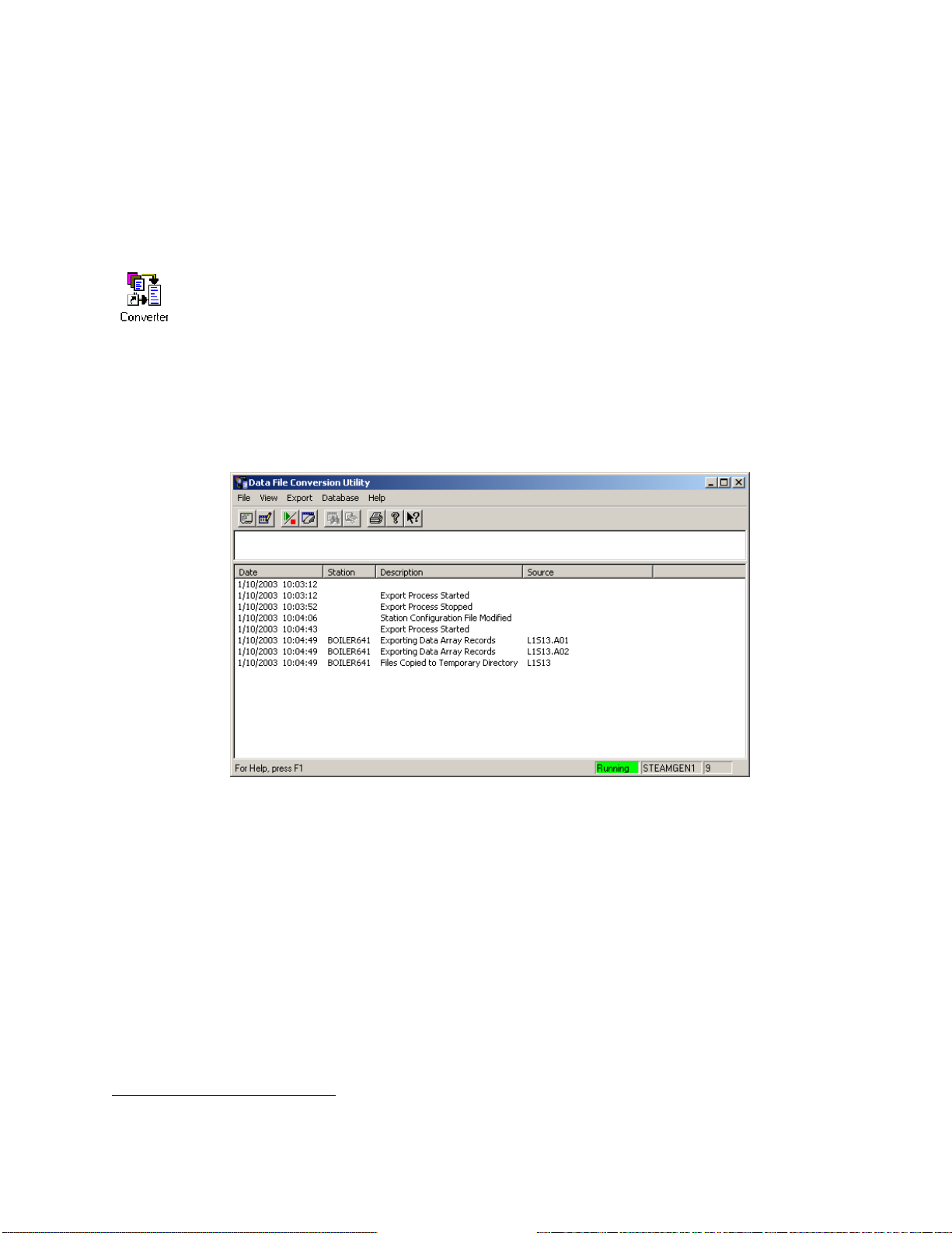
Step 6 - Start the Export Process - Once configuration is complete, the export process can be
activated. The Data File Conversion Utility will then search for files to be converted, and
conversions will begin. The operator can observe the progress of the conversions in the monitor area
of the window. See 'Activating the Export Process' for details.
NOTE: With the exception of the EXPDLL.INI file, users should not attempt to edit configuration
files with a text editor. Always use the dialog boxes and utilities provided.
Starting the Data File Conversion Utility
To start the Data File Conversion Utility, OpenBSI communications must already be active.5 Click
on StartProgramsOpenBSI Tools Collection Programs Converter. A message may
appear concerning database files being loaded. The Data File Conversion Utility window will then
appear. This window includes a monitor area which displays messages concerning the operation of
the utility.
5
See the OpenBSI Utilities Manual (document# D5081) for information about configuring and starting OpenBSI
communications.
Addendum to D5082, D5083, D5120 Using the Data File Conversion Utility
ADD-3
Page 98

Specifying Initialization Parameters
For the Data File Conversion Utility to function correctly, certain information must be specified
before exporting is started. This information is defined in the Data File Conversion Setup dialog box.
To call up this dialog box, click on the icon, shown above, or click on FileInitialization.
Parameters Page:
The first page of the dialog box defines initialization parameters, and is accessible by clicking on the
"Parameters" file tab. The fields on the page are described, below:
Time Interval specifies the interval (in seconds) at which the Data File
Conversion utility will check to see whether Collector /
Scheduler /Harvester data files exist which require
conversion. This interval must be short (fast) enough to
prevent files from being used up. See IMPORTANT note,
below:
IMPORTANT
No more than 99 (999 for Harvester) data files of a given file type are saved for a given
collection name/node name. Once they have been used, data will wrap-around and overwrite the
existing files. IT IS THE RESPONSIBILITY OF THE USER TO RETRIEVE DATA (BY
USING THE DATA FILE CONVERSION UTILITY) BEFORE THESE FILES ARE
OVERWRITTEN; OTHERWISE IMPORTANT DATA MAY BE LOST.
Using the Data File Conversion Utility Addendum to D5082, D5083 D5120
ADD-4
Page 99

Error History Buffer Size specifies the number of errors which may be saved in each
station's dedicated error history buffer. Any change to this
parameter will cause the Error History to be cleared, losing all
previous error messages.
Monitor Size defines the number of status messages which may exist in the
monitor area at any one time.
Copy Path specifies the file path where the original, unconverted data
files should be copied after conversion/exporting has been
completed. This is to prevent them from being re-used during
the next file conversion. If this parameter is left blank, the
individual date files will be automatically deleted following
conversion. NOTE: Do NOT specify the copy path to be the
same as the path where the OpenBSI Data Collector,
Scheduler, or Harvester generate their data files, or problems
may occur.
Station Interval specifies the length of time (in seconds) that the Data File
Conversion utility will wait before attempting to process the
next station. This value can range from 0 to 3600.
Click on the [OK] push button to save the parameters, and exit the dialog box.
NOTE: Initialization parameters are stored in the system directory under the name DFCU.INI. A
description of this file is included at the end of this addendum.
Addendum to D5082, D5083, D5120 Using the Data File Conversion Utility
ADD-5
Page 100

Files Page:
The second page of the dialog box is accessible by clicking on the “Files” tab. This page allows you
to specify that you would like timestamps included in the first row of all list files you export. If you
select “Timestamp exported UOI list files”, an entry LIST.CREATE.TIME with an accompanying
timestamp will be the first record exported. The format of the time / date in the timestamp of this
record is governed by “Regional Settings” in the Windows™ Control Panel. The timestamp
corresponds to the time the data was exported, not the time it was collected; however these are
usually within a few moments of each other, depending upon your configuration settings.
If you check the “Use UTC time for timestamped records” box, all timestamps in
array/archive or audit files will be converted to Universal Time (UTC) when exported
via the Data File Conversion Utility.
Export Libraries Page:
The third page of the dialog box defines which dynamic link libraries (DLLs) should be used to
convert and export the data files. It is accessible by clicking on the "Export Libraries" file tab.
Instructions for using this page of the dialog box are included later in this addendum, in the section
'Configuring and Selecting Export DLLs'.
Using the Data File Conversion Utility Addendum to D5082, D5083 D5120
ADD-6
 Loading...