

Page 1

Training Manual
D301660X412
May, 2010
ObjectServer for Beginners
ObjectServer
Remote Automation Solutions
www.EmersonProcess.com/Remote
Page 2

D301660X412 - ObjectServer for Beginners
This page has been left intentionally blank
ii
Page 3

D301660X412 - ObjectServer for Beginners
Table of Contents
Chapter 1 – Introduction – What is ObjectServer? ............................................ 1-1
Objects ............................................................................................................................. 1-2
Bristol Controllers ............................................................................................................. 1-2
Automated Control........................................................................................................ 1-2
Supervisory Control ...................................................................................................... 1-2
ObjectServer Database .................................................................................................... 1-2
Data Collection ............................................................................................................. 1-2
OPC Servers .................................................................................................................... 1-3
OPC Data Server.......................................................................................................... 1-3
Support for Legacy Applications ................................................................................... 1-3
OPC .................................................................................................................................. 1-3
OLE .................................................................................................................................. 1-3
The OPC Standard ....................................................................................................... 1-3
OPC Clients ...................................................................................................................... 1-4
WebTookit ........................................................................................................................ 1-4
Getting Data into the ObjectServer Database .................................................................. 1-5
The Controller-to-ObjectServer Communication Chain ................................................ 1-5
Alarm Data Collection ....................................................................................................... 1-6
Polled Data Collection ...................................................................................................... 1-6
Report by Exception (RBE) Collection.............................................................................. 1-7
Chapter 2 – OpenBSI and ObjectServer Installation ......................................... 2-1
Before You Begin ............................................................................................................. 2-1
Role 1 – Complete OPC Server ................................................................................... 2-1
Role 2 – Centralised Data Collector ............................................................................. 2-2
Role 3 – OPC Access to another Computer ................................................................. 2-3
Installation Option 1 - Complete OPC Server ............................................................... 2-5
Installation Option 2 – Centralised Data Collector ........................................................ 2-6
Installation Option 3 - OPC Access to Another Computer ............................................ 2-7
ObjectServer Installation – Step by Step .......................................................................... 2-7
Chapter 3 – Basic Bristol Controller Preparation .............................................. 3-1
Bristol RTU/Controllers and their Control Strategy Files .................................................. 3-1
NW3000 Series Controllers .......................................................................................... 3-1
ControlWave Controllers .............................................................................................. 3-2
Marking Signals for Collection by ObjectServer ............................................................... 3-2
Using ACCOL Workbench ................................................................................................ 3-4
1. Creating an Alarm Signal.......................................................................................... 3-4
2. Creating a Global Signal........................................................................................... 3-5
3. Creating an RBE Signal............................................................................................ 3-6
Saving, Compiling, and Downloading the ACCOL Load .............................................. 3-6
Using ControlWave Designer ........................................................................................... 3-7
1. Creating an Alarm Variable ...................................................................................... 3-7
2. Creating an RBE Variable ........................................................................................ 3-8
3. Marking Local Variables for Collection ................................................................... 3-10
4. Manually Marking Global Variables for Collection .................................................. 3-10
5. Setting All Global Variables for Collection .............................................................. 3-11
Compiling and Downloading the ControlWave Project ............................................... 3-12
Chapter 4 – ObjectServer Preparation ................................................................ 4-1
Step 1: Start OpenBSI ...................................................................................................... 4-1
Step 2: Start ObjectServer Database ............................................................................... 4-1
Step 3: Import Device and Signal Information from OpenBSI .......................................... 4-2
NW3000 Setup Tool ..................................................................................................... 4-3
The NW3000 System Set-up Wizard ................................................................................ 4-3
iii
Page 4

D301660X412 – ObjectServer for Beginners
OpenBSI AutoStart Page .............................................................................................. 4-3
Message Buffers Page ................................................................................................. 4-4
Device Health Checking Page ...................................................................................... 4-4
Remote Alarm Support Page ........................................................................................ 4-5
RBE Support Page ....................................................................................................... 4-5
Polling Support Page .................................................................................................... 4-6
Signal Import Settings .................................................................................................. 4-7
Summary of Settings .................................................................................................... 4-7
NW3000 Device Set-up Wizard ........................................................................................ 4-8
Import from Netview Page ............................................................................................ 4-8
RBE Support Page ....................................................................................................... 4-8
Polling Support Page .................................................................................................... 4-9
Device Set-up Summary Page ..................................................................................... 4-9
Database Builder ........................................................................................................ 4-10
Template Builder ........................................................................................................ 4-11
Confirming that Data is Being Collected ......................................................................... 4-11
Chapter 5 – Monitoring Bristol Controllers ........................................................ 5-1
Starting the Monitor .......................................................................................................... 5-1
Viewing Device Status ...................................................................................................... 5-2
Viewing ACCOL Versions ................................................................................................ 5-3
Viewing RBE Stats ........................................................................................................... 5-5
Viewing Alarm Stats ......................................................................................................... 5-6
Viewing Template Stats .................................................................................................... 5-6
Viewing Alarms ................................................................................................................. 5-7
Viewing All Alarms ........................................................................................................ 5-7
Viewing Filtered Alarms ................................................................................................ 5-8
Acknowledging Alarms ..................................................................................................... 5-8
Viewing Signals ................................................................................................................ 5-9
Signal Filters ................................................................................................................. 5-9
Using a Device Filter .................................................................................................. 5-10
Modifying Signal Properties ............................................................................................ 5-11
Chapter 6 – Basic Configuration Changes ......................................................... 6-1
Adding a Controller ........................................................................................................... 6-1
Adding the New Controller to NetView ......................................................................... 6-2
Updating ObjectServer ................................................................................................. 6-3
Removing a Controller ...................................................................................................... 6-5
Adding Signals/Variables ................................................................................................. 6-6
Removing Signals/Variables ......................................................................................... 6-8
Changing Signal Descriptions from within the Load File .................................................. 6-8
Adding Signal Descriptors ............................................................................................ 6-8
Updating Basename Descriptors in ACCOL ................................................................ 6-9
Updating Variable Descriptions with ControlWave Designer ………………………….6- 10
Getting Descriptor Changes into the ObjectServer Database .................................... 6-12
Changing Data Collection Rates .................................................................................... 6-14
Making Changes to RBE Settings .................................................................................. 6-16
Setting the RBE Mode in Workbench (ACCOL) ......................................................... 6-16
Setting the RBE Module in ControlWave Designer .................................................... 6-18
Updating RBE Settings in ObjectServer ..................................................................... 6-18
Chapter 7 – Displaying ObjectServer Data in OPC Clients ............................... 7-1
Getting ObjectServer Real-time Data into OPC Clients on the Same Computer ............. 7-1
An OPC Tag is a Query ................................................................................................ 7-3
Preparation ................................................................................................................... 7-5
Getting ObjectServer Real-time Data into Genesis32™ .................................................... 7-6
Using ObjectServer with Legacy GraphWorX™ HMIs ................................................. 7-12
iv
Page 5

D301660X412 - ObjectServer for Beginners
Modifying a Tag in GraphWorX ...................................................................................... 7-13
Getting ObjectServer Real-time Data into InTouch® ...................................................... 7-15
Using the Text Tool in InTouch to Show ObjectServer Tags ...................................... 7-24
Getting ObjectServer Real-time Data into iFix™ ............................................................ 7-27
Using the iFix Datalink Stamper to Display ObjectServer Tags ................................. 7-31
Getting Real-time Data into OPC Clients from a Remote Workstation ........................... 7-34
ObjectServer and Licensing for Remote Workstation Clients ..................................... 7-34
Troubleshooting .............................................................................................................. 7-38
My OPC Server doesn’t connect to the ObjectServer database ................................ 7-38
My OPC server connects to the ObjectServer database, but it is not licensed! ......... 7-39
Getting ObjectServer Alarm and Event Data into an OPC Client ................................... 7-43
Alarm Data.................................................................................................................. 7-44
Getting ObjectServer OPC Alarm and Event Data into AlarmWorX32 ....................... 7-45
Chapter 8 – Troubleshooting and Maintenance ................................................. 8-1
Data Collection ................................................................................................................. 8-1
Confirming that Data is Being Collected ....................................................................... 8-1
Fixing ACCOL/ControlWave Version Mismatches ....................................................... 8-2
Running the NW3000 Signal Builder and Template Builder in Monitor Mode .............. 8-2
Troubleshooting RBE Failure ....................................................................................... 8-3
Troubleshooting Alarm Collection Failure ..................................................................... 8-4
OPC Server ...................................................................................................................... 8-4
Starting the OPC Server ............................................................................................... 8-4
Automatically Starting the OPC Server ........................................................................ 8-4
Manually Starting the OPC Server ............................................................................... 8-5
Confirming that the OPC Server is Running on a Server ............................................. 8-5
Confirming the OPC Server is Running on a Client ...................................................... 8-5
Confirming that the OPC Server is Connected ............................................................. 8-5
What to do if the OPC Server is not Connected ........................................................... 8-6
Workstation Licensing ...................................................................................................... 8-8
Determining if a Workstation is Licensed ..................................................................... 8-8
Troubleshooting Licensing Problems ........................................................................... 8-8
System Maintenance ...................................................................................................... 8-10
Remote Automation Solutions
www.EmersonProcess.com/Remote
Page 6

Chapter 1 – Introduction – What is ObjectServer?
d
Clie
I
(
(
Chapter 1 – Introduction – What is ObjectServer?
This chapter introduces ObjectServer and provides a broad overview of what it does.
ObjectServer is an OPC Server for Bristol Controllers, providing OPC
real-time and alarm & event data to any OPC Compliant software –
normally Human Machine Interface (HMI) or SCADA software packages
The following graphic shows ObjectServer’s relationship to various components in
the technical environment:
r
ObjectServer
(Workstation)
Party OPC
3
nt HMI
OPC Servers
Workstation components)
i
ObjectServer
(Server)
Database
Server component)
OpenBS
Bristol
Controllers
Objects
Expanding on our definition in the box above, ObjectServer takes real-time and
alarm data from objects that Bristol controllers manage and make it available to thirdparty OPC clients using OPC servers (that provide the data from a central database).
Let’s examine each part of this statement.
Issued 01-10 1-1 ObjectServer for Beginners
Page 7

Chapter 1 – Introduction – What is ObjectServer?
Objects
Bristol Controllers
Objects are tanks, pumps, valves, filters, or any kind of plant
equipment used to monitor or control a product that requires
processing (such as water, gas, or oil).
Sensors attached to these objects generate electronic impulses –
signals – which they send to controllers. The values the sensors
send to the controllers (such as flow, pressure, or temperature)
are called “input signals”. Input signals provide information on the
state of the objects.
In turn, the controllers send values – “output signals” – to the
objects. Output signals can change the state of the object, by
opening or closing a valve or switching a pump on or off.
ObjectServer communicates with all of the controllers in the
whole process system. It retrieves the object data and places it in
a storage location, or database. The OPC server accesses the
database and provides this data to OPC clients.
Human supervisors can then monitor and control all the objects
in the process from an OPC client workstation.
Automated Control
Bristol controllers use programs you write (called “control
strategy files” or “loads”) to control the objects (tanks, pumps,
valves, and so on). Currently there are two types of Bristol
controllers: the older NW3000 series (which are programmed in
ACCOL) and the newer ControlWaves, (which are programmed
with an IEC 61131 control language). ObjectServer can send
data to and retrieve data from both types of controllers.
ObjectServer Database
Supervisory Control
Even though the controllers are managing the objects, you need
to monitor whether a particular pump is actually on or off or
whether a particular tank is full yet. You may also need to
override the controller program and manually control the objects.
ObjectServer enables you to do this by collecting data from the
controllers and, using its OPC server, making the data available
to any OPC client (through its Human Machine Interface).
ObjectServer ”serves up” or directs data from controllers to OPC
clients, but requires only a minimum of ”know how” and
configuration effort on your part to get that data collection started.
Data Collection
ObjectServer uses a program called RDI3000 to communicate
with OpenBSI to get real-time controller data, and place it into the
database. A section at the end of this chapter explains this
process in greater detail.
ObjectServer for Beginners 1-2 Issued 01-10
Page 8

Chapter 1 – Introduction – What is ObjectServer?
OPC Servers
OPC Data Server
Unlike OpenEnterprise, ObjectServer does not include its own
OPC
OLE
HMI. Instead, it supplies OPC data to third-party OPC clients (or
HMIs) via its OPC servers.
The ObjectServer OPC server and OPC Alarm and Event
servers serve OPC Data Access data and OPC Alarm and Event
data from the ObjectServer database directly to OPC clients.
Support for Legacy Applications
The ObjectServer OPC server supports legacy OPC client
applications that have been configured using the Bristol BSI OPC
server (also often referred to as the “Bristol Standalone OPC
Server”). OPC tags configured with the Bristol BSI OPC server
would normally require reformatting to be read. However, you
can configure the ObjectServer OPC server to support tags in the
Bristol BSI OPC Server format, reducing the need for display
modification. More instructions on this procedure appear later in
this guide (see Chapter 7 page 12).
OPC stands for OLE for Process Control. So, firstly we need to
understand what OLE is.
OLE (Object Linking and Embedding) is a Microsoft®-developed
technology. It initially allowed you to take objects from one
application (such as Excel® spreadsheets) and embed them in
another application (such as a Word document). In this example
Excel is the server and Word is the client.
OLE technology was later written into Microsoft’s COM
(Component Object Model) and then DCOM (Distributed
Component Object Model), which enabled programs running on
different PCs over a network to communicate and exchange
data.
The OPC Standard
The OPC Foundation (www.opcfoundation.org) then added
extensions to OLE technology to standardize the process of
exchanging data in process control applications in a server-client
environment. OPC Servers obtain process control data from a
source and make it available to OPC client applications.
Issued 01-10 1-3 ObjectServer for Beginners
Page 9

Chapter 1 – Introduction – What is ObjectServer?
OPC Clients
WebTookit
OPC client programs are often called HMI applications because
they provide process data in a form that humans can easily
understand.
OPC clients are applications that display real-time or alarm data
from OPC servers in a graphical form. For instance, a tank level
can be drawn as a rectangle that shrinks or grows according to the
actual level of the tank.
Some examples of third-party OPC client applications are
Genesis32™, iFix™, Citect, or InTouch®. OPC clients can request
data from any OPC server. The ObjectServer OPC server provides
these OPC clients with data from Bristol controllers. ObjectServer
does not have its own OPC client; instead, it provides data to OPC
clients from third-party vendors.
When you create a
dynamic object on a
display, you can browse
available OPC servers
for OPC tags. The OPC
client will list the
ObjectServer OPC
server. If you select the
ObjectServer OPC
server, you can browse
for OPC tags, which
you can then drop into
the data source field for
the dynamic object.
WebToolkit is a web based application from OpenEnterprise
Development that enables you to display ObjectServer data in a
web browser without using OPC. This removes the need for
dedicated OPC client workstations.
If you would like to view your ObjectServer data from any location
over the Internet, consider setting up a web server running
WebToolkit rather than investing in one or more dedicated OPC
client workstations.
For more information on WebToolkit, see the manual WebToolkit
for Beginners.
What are OPC Tags?
OPC tags are strings that the OPC
server uses to identify the object
values that you want to view.
Typically, an OPC tag includes the
OPC server’s ProgramID, the
PrimaryID of the signal, and the
signal property. The OPC server
allows you to browse for controller
tags as objects from any OPC client.
It then inserts the selected object into
the display as a tag. There will be
more about tags later.
ObjectServer for Beginners 1-4 Issued 01-10
Page 10

Chapter 1 – Introduction – What is ObjectServer?
Getting Data into the ObjectServer Database
The ObjectServer database stores data collected from your network of remote
process controllers. OpenBSI, using the communications driver program RDI3000,
handles the actual communication between both types of Bristol controllers and the
ObjectServer database. Typically, OpenBSI and RDI3000 both run on the
ObjectServer computer.
The Controller-to-ObjectServer Communication Chain
ObjectServer
Database
RDI3000
OpenBSI
ObjectServer
PC
Controller
Network
Data goes from the controllers into the ObjectServer database by three methods:
• Alarm Data Collection
RTU sends an alarm message to ObjectServer when a signal value passes a
predetermined limit
• Polled Data Collection
ObjectServer asks RTU for specific signal values at regular intervals
• Report By Exception (RBE) Collection
RTU sends a change of value report to ObjectServer
Note that the RTU initiates two of the methods while ObjectServer initiates one. Let’s
look at these three methods in more detail.
Issued 01-10 1-5 ObjectServer for Beginners
Page 11

Chapter 1 – Introduction – What is ObjectServer?
Alarm Data Collection
Alarms occur in a controller when a particular
signal goes outside a pre-defined range or
changes state into an alarm state. Typical alarm
conditions might be that a liquid level is too high,
a temperature is too low, or that a pump has
failed to start.
The Bristol controller sends a message to
ObjectServer when an alarm condition occurs.
Once ObjectServer receives the alarm message,
it raises the alarm. The ObjectServer OPC
Alarms and Events Server then allows the thirdparty OPC client software to display the alarm
message to the monitoring operator.
The alarm message tells the operator that something potentially serious has
happened.
An alarm means something
just happened and needs
attention. For example, the
controller detects that a
pump has failed or a
pressure signal is too
high….
Polled Data Collection
Most people are familiar with the term polling in
connection with elections. Every two years, for
example, your town might have an election for
mayor, and people go to the polls to vote. That’s
similar to the type of polling we’re discussing
here. When using the polled data collection
method, ObjectServer sends data requests to the
controllers according to a pre-defined schedule.
For example, you may want to collect a certain
group of signals every two hours.
All signals collected as part of the same
scheduled collection are said to be in the same
scan “timeclass”. For example, if you need to
collect hourly flow totals you define an hourly
timeclass, and all hourly flow totals are collected
as part of that timeclass. An ObjectServer tool
called Poll List Builder automatically includes
signals for a particular scan timeclass into structures called “poll lists”. Similarly, if
you had other signals that you wanted collected every minute, you would create a 1minute scan time class, and so on.
Polled Data Collection
operates on a schedule,
such as “Collect all flow
total signals every hour” or
“Collect all logical signals
every minute”. It doesn’t
matter whether the data
changes; Polled Data
Collection just collects the
values anyway.
ObjectServer for Beginners 1-6 Issued 01-10
Page 12

Chapter 1 – Introduction – What is ObjectServer?
S
Report by Exception (RBE) Collection
The controller initiates Report by Exception
(RBE) Collection. Important differences exist
between data collected by polling and data
collected by RBE.
With polling-collected data, the ObjectServer
requests the data from the Bristol controller at
regular intervals. However, with RBE-collected
data, the controller reports to ObjectServer
only when a signal’s value changes.
With polling, ObjectServer collects the data at
the specified time regardless of whether there
has been a change. With RBE, if a signal
doesn’t change, no communication occurs
between the controller and ObjectServer. If
your data changes slowly, this can be a much
more efficient use of network resources.
With polling, if a signal’s value changes just
after a poll, it could be a comparatively long time before ObjectServer registers that
change (based on the frequency of polling). However, with RBE, as soon as the
signal’s value changes, the RTU notifies ObjectServer of the change.
For logical (Boolean) signals, a report is sent to ObjectServer when the signal
changes state (from on to off or off to on). For analog signals, a report transmits only
if the signal’s value changes significantly from its previous value. The determination
of whether or not a change is significant is controlled by the deadband. The
deadband is a range above and below the signal’s value, and you must configure
that range for every signal within the RTU (though multiple signals can use the same
deadband, making configuration easier).
If the value of an analog signal has not changed more than the deadband since it
was last sent to the ObjectServer, any change is considered insignificant, and no
report is sent to the ObjectServer.
As you can see, RBE collection reduces the amount of data that has to be collected
while allowing changed data to be displayed more rapidly than would be possible via
polled collection.
Well, that’s enough basic information on what ObjectServer is and how it
accomplishes its task in conjunction with OpenBSI. Let’s get started by installing
these programs. The next chapter describes how to do this.
The RBE module in the
controller runs at regular
intervals. It says, “Check to see
if the data is different from the
last time we collected it. If it
hasn’t changed, don’t bother
collecting it. If it has changed,
collect it and send a report of
the change to ObjectServer.”
Value: Collect it?:
SAME
CHANGED ;
SAME
SAME
SAME
CHANGED ;
AME
Issued 01-10 1-7 ObjectServer for Beginners
Page 13

Chapter 1 – Introduction – What is ObjectServer?
[This page intentionally left blank.]
ObjectServer for Beginners 1-8 Issued 01-10
Page 14

Chapter 2 – OpenBSI and ObjectServer Installation
Chapter 2 – OpenBSI and ObjectServer Installation
This chapter describes the installation options for ObjectServer and the process of
installing ObjectServer on your computer.
Before You Begin
Before installing ObjectServer, you need to know and decide what functions or roles
ObjectServer should have on this computer. The options are:
• Complete OPC server, collecting data from Bristol controllers and making the
data available through OPC
• Centralised data collector, collecting data from Bristol controllers and
storing within a local repository
• OPC access to another computer, sourcing OPC data from a centralised
data collector
Role 1 – Complete OPC Server
In this role, the computer acts as both an ObjectServer server and client. It runs
OpenBSI and the ObjectServer database to collect data from Bristol controllers and
serves that data to the ObjectServer client that is installed on this machine.
The ObjectServer client on this computer is an ObjectServer workstation, even
though it exists on the same computer. In order to serve tags, the client requires a
concurrent license from the server that is running on the same machine. When the
ObjectServer client starts, it runs the Workstation License Manager, which connects
with the server’s Concurrent License server to determine that a concurrent license is
available.
A third-party OPC client can then display the data on this machine. Of course, the
ObjectServer database on this machine also serves any remote ObjectServer
workstations that request data, as long as the number of connected workstations
does not exceed the number allowed on the server’s concurrent license.
Issued 01/10 2-1 ObjectServer for Beginners
Page 15

Chapter 2 – OpenBSI and ObjectServer Installation
Serve real-time and alarm
data from Bristol RTUs to
remote ObjectServer
clients. The number of
clients is limited by the
concurrent license on the
Server and
Client of Bristol
Data
ObjectServer
Client
(Requires
concurrent license
on Server)
View OPC
Data on
Server
rd
3
Party
OPC HMI
ObjectServer
Database
OpenBSI
Role 2 – Centralised Data Collector
If this is the intended role, then you only need to install the ObjectServer database.
Of course, you also need to install OpenBSI and configure any RTUs with it before
you run and configure ObjectServer. This computer then becomes a server of Bristol
RTU data to ObjectServer workstations.
The ObjectServer database installation includes a number of components that are
required for serving Bristol data:
• The ObjectServer database
• The Session Manager
• The NW3000 and ControlWave device interface
• Database configuration tools
• The Concurrent License Server (CSL)
• The License Manager
For this role, this computer requires the ObjectServer database but does not need
the ObjectServer client. The ObjectServer client consists of the Data Access OPC
server, the Alarm and Event OPC server, and a client license verification tool called
the Workstation License Manager.
You also need to apply for a concurrent license for any connected ObjectServer
clients (also known as workstations) that want to serve tags to third-party OPC
clients. For example, if you require five ObjectServer workstations to provide tags,
the server must have a concurrent license for five ObjectServer workstations. The
ObjectServer for Beginners 2-2 Issued 01/10
Page 16

Chapter 2 – OpenBSI and ObjectServer Installation
ObjectServer server uses an application called the Concurrent License Server (CSL)
to determine the number of connected workstations. The concurrent license installed
on the server determines how many ObjectServer workstations can connect at the
same time and serve tags.
The following diagram shows how the dedicated server role works.
Serve real-time and
alarm data from Bristol
RTUs to a licensed
number of remote
ObjectServer Clients.
Dedicated Server of Bristol Data
ObjectServer Database
OpenBSI
Bristol RTUs
Role 3 – OPC Access to another Computer
For this role, the computer becomes an ObjectServer client (also known as an
ObjectServer workstation). You install the Workstation License Manager on this
machine, along with the Data Access and Alarm & Event OPC servers. The
ObjectServer client serves OPC tags to local third-party OPC clients as long as the
server to which it connects can provide it with a concurrent license.
Issued 01/10 2-3 ObjectServer for Beginners
Page 17

Chapter 2 – OpenBSI and ObjectServer Installation
d
Client
I
(Obj
r
3
Party OPC
HM
A dedicated Client
of Bristol data
OPC Servers
ectServer Clients)
Request realtime and
alarm data
from
ObjectServer
Server.
So, before you install ObjectServer, it’s essential to determine which options the
computer should perform.
More about “servers and clients”
Like people, computer programs can be either clients or servers. Sometimes the
computer running the program is called a server or a client, but strictly speaking it
is the program that is either a server or a client. The rules are always the same: a
server provides something and a client requests something from the server. With
computers, the commodity is usually data, but with human beings, it could be
anything. Take for instance the chain of servers and clients involved when we eat
out at a restaurant. The restaurant supplies us with a meal when we request it. So
from our point of view, the restaurant is the server.
However, the restaurant has to get the ingredients for our meal from a supplier.
So when the restaurant orders food from its suppliers, the restaurant becomes a
client to the food supplier. The food supplier is now a server to the restaurant.
In the same way, a computer program can be a server in one scenario and a
client in another. For instance, the OPC servers provide OPC data to any thirdparty OPC HMI that requests it, so they are servers in this context. However, to
the ObjectServer database, the OPC servers are always seen as clients, because
they request the data from the database. So, the ObjectServer installation
process refers to the OPC servers as the “ObjectServer client”. They are
collectively referred to as “client” (singular). This expression includes both the
real-time and alarm-event OPC servers.
The following headings show the ObjectServer installation options you can select
based on the role you’ve chosen for the computer.
ObjectServer for Beginners 2-4 Issued 01/10
Page 18

Chapter 2 – OpenBSI and ObjectServer Installation
Installation Option 1 - Complete OPC Server
If the installation computer runs the ObjectServer database (collecting data from
Bristol RTUs and displaying data from the database via a third-party OPC client
HMI), then select the following options from the OpenBSI CD when you install
ObjectServer:
• OpenBSI Network Edition – enables the Bristol controller network to collect
Bristol controller data.
• ACCOL Workbench – enables you to write control strategy files for Bristol
33x controllers.
• ControlWave Designer – enables you to write control strategy files for
ControlWave controllers.
• ObjectServer database – stores collected data that the ObjectServer client
(that is, the OPC servers) can access.
• ObjectServer client – provides the real-time and alarm-event OPC servers,
which enable third-party OPC HMIs to obtain and display Bristol OPC data
from the ObjectServer database.
Select these options from the Select Features screen to enable your computer to be
a dual server and client of Bristol OPC data.
Select Network Edition, along with
ACCOL Workbench (if using Bristol 33x
RTUs), and ControlWave Designer (if
using ControlWave RTUs)
Also, select the ObjectServer Database
and the ObjectServer client option from
here.
Issued 01/10 2-5 ObjectServer for Beginners
Page 19

Chapter 2 – OpenBSI and ObjectServer Installation
Installation Option 2 – Centralised Data Collector
If the computer is dedicated solely to serving Bristol RTU data to clients, then select
the following options from the OpenBSI CD when you install ObjectServer:
• OpenBSI Network Edition – enables the Bristol controller network to collect
controller data.
• ACCOL Workbench – enables you to write control strategy files for Bristol
33X controllers.
• ControlWave Designer – enables you to write control strategy files for
ControlWave controllers.
• ObjectServer Database – stores collected data that the ObjectServer client
(that is, the OPC servers) can access..
When you start the installation program, it presents an automatic sequence of
screens (called a “wizard”) from which you select the options you want. One of these
screens is Select Features. Following is a screen shot of the installation options you
need to select from that screen so the computer can function as a dedicated server
of Bristol RTU data.
Select Network Edition, along with
ACCOL Workbench (if using Bristol 33x
RTUs), and ControlWave Designer (if
using ControlWave RTUs)
Also, select the ObjectServer Database
option from here.
ObjectServer for Beginners 2-6 Issued 01/10
Page 20

Chapter 2 – OpenBSI and ObjectServer Installation
Installation Option 3 - OPC Access to Another Computer
If you want the computer to display ObjectServer data that another computer running
the ObjectServer database collects, then when you install ObjectServer you only
need to select the ObjectServer Client option from the installation wizard’s Select
Features screen.
This option installs the real-time and alarm-event OPC servers, which enable thirdparty OPC HMIs obtain and display Bristol OPC data. Of course, you also need to
install the third-party HMI software on this computer.
Select only the ObjectServer
Client option if this is a
dedicated ObjectServer OPC
client workstation.
ObjectServer Installation – Step by Step
1. Place the OpenBSI installation CD into the CD drive on your computer and
close the drive. If “autoplay” is turned off on your computer, when the
contents of the CD are displayed, double click on the OpenBSI.exe program.
If you have “autoplay” turned on, the InstallShield Wizard dialog displays
automatically:
2. The OpenBSI InstallShield Wizard Welcome screen displays:-
Issued 01/10 2-7 ObjectServer for Beginners
Page 21

Chapter 2 – OpenBSI and ObjectServer Installation
Review the warnings (performing any necessary actions) and click Next>
(highlighted above).
3. Read the Licensing Requirements carefully (click Print to print the
requirements). Select I accept the terms of the license agreement and
click Next>.
ObjectServer for Beginners 2-8 Issued 01/10
Page 22

Chapter 2 – OpenBSI and ObjectServer Installation
4. The Choose Destination Location dialog shows the default installation
location for the software (c:\Program Files\OpenBSI), but you can change this
location by clicking Browse. Click Next>.
5. Once the Select Features screen displays, scroll through it carefully to
determine the programs you want to install. (If you are uncertain which
options to select, review the Before You Begin section at the beginning of this
chapter.)
You can click Cancel at this point if you need to review the installation options
(you can restart the installation later). Once you know what options you need,
click Next> to continue.
Issued 01/10 2-9 ObjectServer for Beginners
Page 23

Chapter 2 – OpenBSI and ObjectServer Installation
6. If you are installing only the ObjectServer client, one more selection screen
displays before the installation begins. Use this screen to identify the name of
the computer that houses the ObjectServer database to which we want to
connect. Remember: use the server’s Windows domain name rather than an
alias configured in the Hosts file (see below). Click Next>.
ObjectServer for Beginners 2-10 Issued 01/10
Page 24

Chapter 2 – OpenBSI and ObjectServer Installation
7. The Installshield Wizard begin installing the OpenBSI and ObjectServer
products that you selected. The wizard displays informative messages as the
installation proceeds, but you do not need to do anything until the final page
(OpenBSI Installation Complete) of the wizard displays.
Finalizing the installation requires that you restart the computer, so the
recommended actions are to leave the Yes, I want to restart my computer
now option selected and click Finish.
However, if you need to save any work or do anything else first, select the No,
I will restart my computer later option and click Finish. You will need to
restart the computer after you finish your tasks.
When the computer reboots, you can begin coding the control strategy
programs for controllers. That is the subject for the next chapter.
Issued 01/10 2-11 ObjectServer for Beginners
Page 25

Chapter 2 – OpenBSI and ObjectServer Installation
[This page intentionally left blank.]
ObjectServer for Beginners 2-12 Issued 01/10
Page 26
Chapter 3 – Basic Bristol Controller Preparation
s
r
Chapter 3 – Basic Bristol Controller Preparation
This chapter briefly explains how you ensure that the control strategy files you create
and download to the Bristol controllers work with ObjectServer.
Bristol RTU/Controllers and their Control Strategy Files
As we have seen, Bristol controllers
come in two basic forms: the older
NW3000 Series (that includes the
DPC 3330, DPC 3335, RTU 3305, or
RTU 3310) and the newer
ControlWave series (that includes
the ControlWave, ControlWave
MICRO, and ControlWave LP,
among others).
These controllers execute a predefined program (called a control
strategy) which reads data from
process instrumentation (flow
meters, pressure transmitters, etc.),
performs calculations based on the
data collected, and sends out
commands to instrumentation
(switches, valves, etc.)
NW3000 Series Controllers
You program the
NW3000 Series
devices with a
language called
ACCOL II, using the
ACCOL Workbench
program.
Network 3000
eries Controlle
You download the resulting file (called the ACCOL “load”) into the computer. The
primary structure for storing an individual data value (pump status, flow reading, etc.)
in the ACCOL load is called an ACCOL signal.
Are RTUs and Remote
Controllers the same?
If you study the theory of control
systems there are slight differences
between these terms, but for our
purposes, they all mean the same
thing. RTU is just an abbreviation for
the term remote terminal unit, which
is basically the same thing as a remote
process controller. Sometimes
people will just use the term femote.
You might also hear people say DPC
(distributed process controller.) You
may even hear someone say node,
which is a reference to the fact that a
controller can serve as part of a
network.
All of these terms refer to a smallcomputerized device located at a
remote site that collects data from
instrumentation and performs control
operations based on the data it
collects.
Issued 01-10 3-1 ObjectServer for Beginners
Page 27

Chapter 3 – Basic Bristol Controller Preparation
ControlWave Controllers
For ControlWave-series controllers, you
write the control strategy in any of five IEC
61131-3 languages, using a program called
ControlWave Designer. (IEC 61131-3 is
an international standard for process
control programming languages.)
You download the resulting file (called a
ControlWave project) into the ControlWave
controller. The primary structure for storing a data
value (temperature reading, valve position, etc.)
in the ControlWave project is called a variable,
and is equivalent to a ”signal” in a 33xx controller.
NOTE: ObjectServer makes no distinction
between the terms “signal” and “variable”; they
are all referred to as “signals”. Other
manufacturers may use the word:”tag” to refer to
the same thing. These three terms—tag, signal
and variable—are often used interchangeably
The principles for ensuring that ObjectServer can collect signal data are the same no
matter what language is used.
ControlWave
series Controller
What’s “downloading”?
Downloading means transferring
programs and/or data from one
device to another. In this case,
we’re downloading a file from the
computer to the controller.
Marking Signals for Collection by ObjectServer
Important - For ObjectServer to collect and store a signal (in an ACCOL load)
or a variable (in a ControlWave project) in its database, that signal must fall into
one of the following categories.
• Alarm (ACCOL and ControlWave loads): Any signal or variable configured as
an alarm is automatically collected when it enters an alarm state or returns to a
normal state. Normally these are signals important for alerting operators, such as
when a pre-determined condition (like a maximum tank level) is exceeded.
Analog alarm signals are also automatically collected via polling, unless you
configure them as RBE within the RTU.
• Global (ACCOL loads only): A global signal in ACCOL is marked for collection
via Polled List collection. ObjectServer simply collects these signals at a fixed
rate (such as once per minute). You configure this rate once for each RTU, so all
polled signals for a particular RTU are collected at the same frequency or rate.
ObjectServer for Beginners 3-2 Issued 01-10
Page 28

Chapter 3 – Basic Bristol Controller Preparation
NOTE
A signal marked as “global” in ACCOL is included in the .SIG file. This
means that ObjectServe marks it for automatic polling collection. This is not
the case for ControlWave variables. ControlWave variables marked as
“global” are simply marked as being available to all program organization
units (POUs) and are not automatically marked for ObjectServer collection.
To mark a ControlWave variable for ObjectServer collection, be sure the
check both its PDD and OPC parameters.
• RBE (ACCOL and ControlWave loads): The controller sends a report by
exception (RBE) signal to ObjectServer whenever a signal value changes by
more than a pre-configured amount (called the ”deadband”). You can configure a
deadband of zero, which ensures that all signals go to the ObjectServer.
• PDD (ControlWave loads only): Marking a variable as PDD (Process Data
Directory) and OPC (OLE for Process Control) means that the variable is marked
for polled collection by ObjectServer and is also viewable using OpenBSI’s
Dataview utility.
• OPC (ControlWave loads only): Marking a variable as OPC (OLE for Process
Control) and PDD (Process Data Directory) means that the variable is marked for
polled collection by ObjectServer, and is also viewable using OpenBSI’s
Dataview utility.
Following are the steps within ACCOL Workbench and ControlWave Designer that
you need to complete to identify the data (signals or variables) ObjectServer collects.
NOTE
This section does not tell you everything you need to know when using
ACCOL Workbench or ControlWave Designer. Instead, it just highlights the
parts which are related to whether a signal or variable becomes a part of the
ObjectServer database. It doesn’t give detailed instructions. If you need help
using ACCOL Workbench, see the ACCOL Workbench User Manual
(document# D4051). If you need help using ControlWave Designer, see the
Getting Started with ControlWave Designer Manual (document# D5085).
Issued 01-10 3-3 ObjectServer for Beginners
Page 29

Chapter 3 – Basic Bristol Controller Preparation
Using ACCOL Workbench
First, let’s use ACCOL Workbench to see how to create signals ObjectServer
collects. Use ACCOL Workbench to create control strategy files for NW3000 Series
controllers.
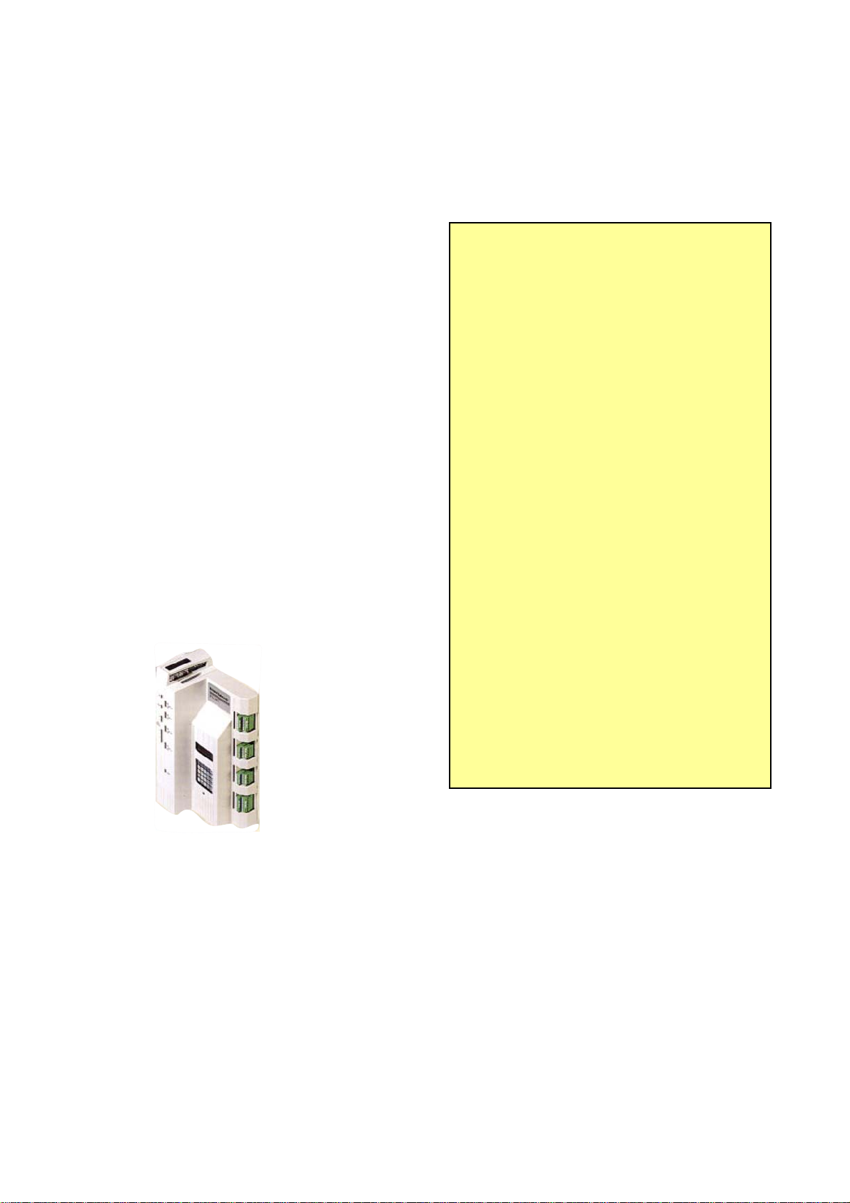
1. Creating an Alarm Signal
On the General tab of
the Signal Properties
dialog box for the
signal, choose either
Logical Alarm or Analog
Alarm as the signal’s
Type.
The Type should be either Logical Alarm or Analog Alarm.
On the Settings tab of
the Signal Properties
dialog box for the
signal, select Alarm
Enable.
Select the Alarm Enable check box.
ObjectServer for Beginners 3-4 Issued 01-10
Page 30
Chapter 3 – Basic Bristol Controller Preparation
For analog alarm
signals, you must also
specify at least one
alarm limit. You should
also specify an alarm
deadband.
Click Alarm Limits to
begin this configuration.
Click Alarm Limits to configure one or more alarm limits
for analog alarm signals.
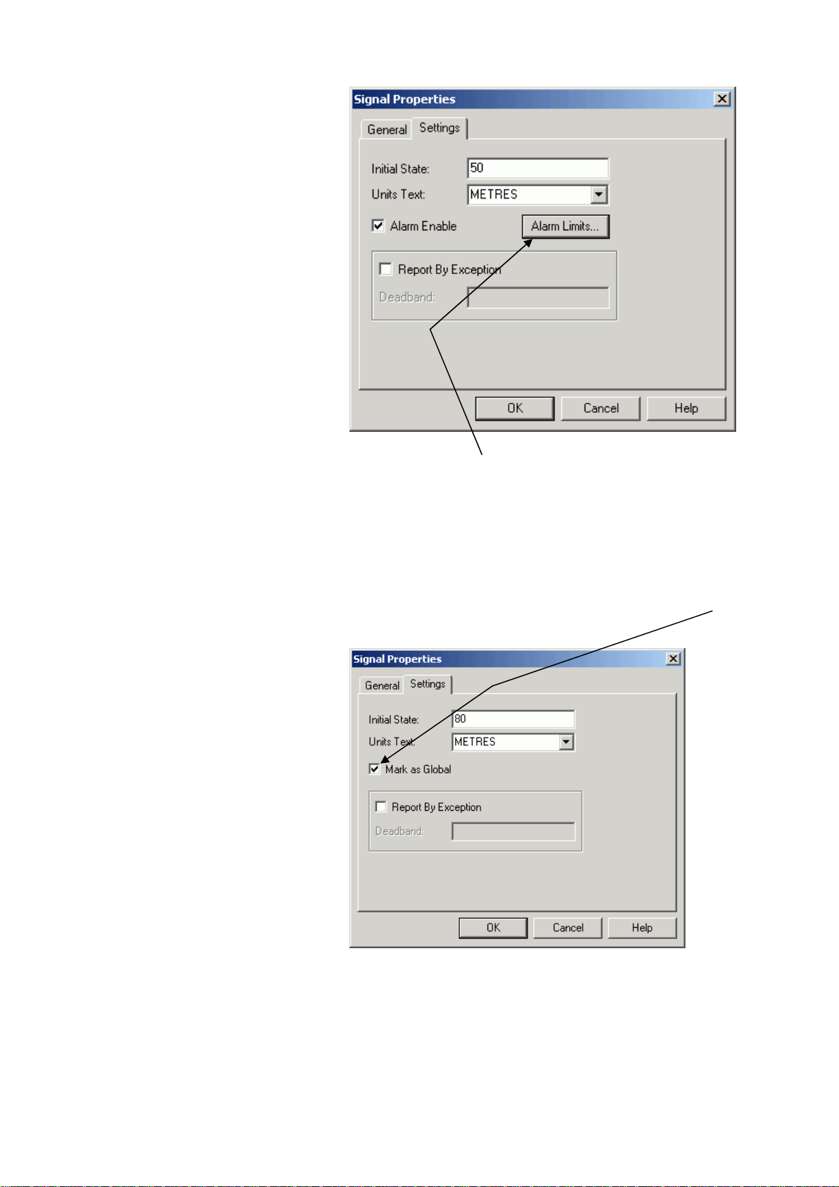
2. Creating a Global Signal
On the Settings tab of
the Signal Properties
dialog box you should
select the Mark as
Global check box.
To make a signal global, select the Mark as Global check
box.
Issued 01-10 3-5 ObjectServer for Beginners
Page 31

Chapter 3 – Basic Bristol Controller Preparation
3. Creating an RBE Signal
On the Settings tab of
the Signal Properties
dialog box for the
signal, select the
Report By Exception
check box.
If this is an analog
signal, you must enter
a deadband. Do not
leave the deadband
field blank, or you will
overload your
communications
network!
You must also add an
RBE module to the RTU
load, typically in task
zero. This is discussed
in the RBE section of
the ACCOL II
Reference Manual
(document# D4044).
Select the Report By Exception check box to ensure this is
an RBE signal.
You must specify a deadband if this is an analog signal.
Saving, Compiling, and Downloading the ACCOL Load
• When you have finished editing in ACCOL Workbench, save the ACCOL
source file. Click File Æ Save or click the Save icon.
• You must then build the ACCOL load (*.ACL) file from the ACCOL source
file using the ACCOL Workbench’s Build command. Click Actions Æ
Build or click the Build icon.
• When the ACCOL load builds successfully without errors, download it into
the Network 3000 controller using the Open BSI Downloader. You access
the Downloader utility from within ACCOL Workbench. Click Actions Æ
Download or click on the Download icon. For full instructions on
downloading, see Chapter 7 of the Open BSI Utilities Manual (document#
D5081).
ObjectServer for Beginners 3-6 Issued 01-10
Page 32

Chapter 3 – Basic Bristol Controller Preparation
WARNING! Test Before Downloading
You should always test your control strategy file (ACCOL load or ControlWave
project) before using it in a live running plant or process. This is especially true
when you’re first learning things. We strongly recommend you do this using a
controller that is currently disconnected from the process, or for which manual
overrides are ready and staffed should something go wrong. This is really
important, because if you download an untested control strategy, you could
potentially lose control of your plant or process due to a programming logic error
and you could damage your equipment or—even worse—hurt somebody! So if
you want to avoid flooding something, blowing something up, or dealing with
personal injury lawyers, always test before you download to a live RTU
connected to a plant!
Using ControlWave Designer
ControlWave Designer enables you to create variables (signals) that ObjectServer
collects. Use ControlWave Designer to create control strategy files for ControlWave
controllers.
1. Creating an Alarm Variable
In your ControlWave Designer project, each
variable which you want to serve as an
alarm must have its own alarm function
block configured. The alarm function blocks
available are:
ALARM_ANALOG, ALARM_STATE,
ALARM_LOGICAL_ON and
ALARM_LOGICAL_OFF.
Descriptions on how to configure these
function blocks are included in the
ControlWave Designer online help and in
the ControlWave Designer Programmer’s
Handbook (document# D5125).
An alarm condition can only be detected at
the time its Alarm function block is
executed.
You must also mark the alarm variable for
PDD and OPC when you create it. See the
variable grid worksheet for the program
organization uint (POU) to the right.
Select the PDD and OPC check
boxes if you also want the variable
to be collected by polling.
Issued 01-10 3-7 ObjectServer for Beginners
Page 33

Chapter 3 – Basic Bristol Controller Preparation
2. Creating an RBE Variable
To designate a variable for
RBE collection in a
ControlWave project, select
the View menu option and
then the Variable Extension
Wizard option..
When the Variable
Extension Wizard dialog
appears, select the RBE
check box for each variable
you want collected via
RBE.
For non-BOOL variables
(REAL, INT, etc.), you
would also specify a
deadband.
ObjectServer for Beginners 3-8 Issued 01-10
Page 34

Chapter 3 – Basic Bristol Controller Preparation
•
This information is saved in
a file called “RBE.INI’ that
you download to the
ControlWave with the
bootproject.
You must also add and
configure a POU containing
the RBE function block.
Finally, configure the
appropriate RBE system
variables depending upon
whether RBE is running on
a serial or IP port. Use the
Variable Extension
Wizard to do this.
For details on all these
subjects, please see the
online help in ControlWave
Designer.
If you do not specify a deadband, this could
strain your network bandwidth when the value
changes rapidly over a period of time.
• If you set the deadband to zero, this may
produce the same effect as having it not set a
deadband at all.
• If the deadband is too small (too narrow a
range), you can again strain your network
bandwidth when a value changes rapidly over
a period of time.
• When setting deadbands, keep in mind the
total range (span) of values that the variable
can have (such as 0-100), as well as the
possible speed and duration of changes the
value may experience. For instance, a
variable with a total range between 0 and 100
may experience a maximum rate of change of
10 units per minute. So, you may feel that a
deadband of 5 is sufficient to keep you
informed without flooding the network.
Issued 01-10 3-9 ObjectServer for Beginners
Page 35

Chapter 3 – Basic Bristol Controller Preparation
3. Marking Local Variables for Collection
Mark local variables for collection when you create them.
When you create a local variable, you can specify that you want ObjectServer to
collet the variable by selecting the PDD and OPC check boxes on this dialog.
4. Manually Marking Global Variables for Collection
ControlWave Designer global variables are variables that all the POUs in the project
can access. You designate variables as global when you create them. Marking these
global variables as PDD and OPC guarantees that ObjectServer collects these
signals during polling at regular intervals. (If you don’t know what a POU is, you
probably need to review the documentation accompanying ControlWave Designer.)
In your ControlWave Designer project, we recommend that you designate only I/O
variables as global. Configure your I/O variables in the ControlWave Designer’s I/O
Configurator first. You can create them as global variables, and then use the
RTU_RESOURCEV worksheet to verify they are marked as PDD and OPC.
ObjectServer for Beginners 3-10 Issued 01-10
Page 36

Chapter 3 – Basic Bristol Controller Preparation
The RTU_RESOURCEV
Global worksheet (with
VAR_GLOBAL selected in the
VAR_GLOBAL in the Usage field identifes a global
variable:
Usage column) lists all
designated global variables in
ControlWave Designer.
If you need to collect only
specific global variables, you
must manually check their
PDD and OPC options (shown
on the right).
Otherwise, use the Device
Resource Settings dialog to
specify that all global
variables should have their
PDD and OPC options
selected See 5. Setting All
Global Variables for for more
information.
If you select the Marked variables option on the
device’s Resource Settings dialog (see heading 5
below) only global variables which also have PDD and
OPC selected appear in the ObjectServer database.
5. Setting All Global Variables for Collection
Any variable which you want to include in the ObjectServer database must
have its own specific PDD and OPC parameter check box selected (as
described previously under 4. Manually Marking Global Variables for
Collection).
In addition, you must specify (on the device’s Resource Settings dialog) whether you
want ObjectServer to collect only those global variables that you have specifically
marked as PPD and OPC or whether you want ControlWave Designer to mark all
global variables for collection by ObjectServer. If you choose this latter option
ControlWave Designer automatically marks all global variables as PDD and OPC.
Issued 01-10 3-11 ObjectServer for Beginners
Page 37

Chapter 3 – Basic Bristol Controller Preparation
The practice we recommend
is that you first explicitly
mark the global variables
that you want ObjectServer
to collect as PDD and OPC.
Then select the Marked
variables check boxes on
this dialog so that only
those variables which you
have explicitly marked for
collection are included in the
ObjectServer database.
However, if you want all
global variables to be part of
the ObjectServer database,
select the All global
variables check boxes in
the PDD and OPC sections
on this dialog. This
automatically marks all
global variables for
Select the Marked variables check boxes to ensure that
ObjectServer only collects the signals you have explicitly
marked as PDD and OPC.
ObjectServer’s polled
collection.
Select the All
global
variables
check boxes
to ensure that
ObjectServer
collects all
global
variables
marked as
PDD and
OPC.
Compiling and Downloading the ControlWave Project
Finally, compile the ControlWave project. Click Build Æ Make or click the Make
icon.
When the ControlWave project compiles successfully, you must download it into the
ControlWave controller. Please heed the warning about downloading on page 3-7. For
details on performing a download into the ControlWave, see the Downloading section of
the ControlWave Designer Programmer’s Handbook (document# D5125).
ObjectServer for Beginners 3-12 Issued 01-10
Page 38

Chapter 4 – ObjectServer Preparation
Chapter 4 – ObjectServer Preparation
This chapter explains how to prepare
ObjectServer so it can run and begin
collecting data from your ControlWave
and NW3000 controllers.
Before you take the steps described in this chapter, you must first complete the
following pre-requisite activities:
1. Configured your controller network using the Netview application.
2. Created your control strategy files and marked all signals or variables for
ObjectServer collection (as described in Chapter 3).
3. Downloaded your control strategy files to all your controllers (as described in
Chapter 3).
4. Installed ObjectServer.
With those pre-requisites accomplished, these are the steps you need to accomplish
to get the ObjectServer database functioning.
Note: The terms “controller”, “RTU”, and
“device” are interchangeable and, for our
purposes all mean essentially the same
thing.
Controller = RTU = Device.
Step 1: Start OpenBSI
Start OpenBSI (which you have previously installed and configured). OpenBSI must
be running for the ObjectServer database to function correctly. How you start
OpenBSI depends upon your particular system configuration and requirements, but
one way is to run NetView:
Start Æ Programs Æ OpenBSI Tools Æ NetView
For further information, see the OpenBSI documentation (available on the OpenBSI
CD).
Step 2: Start ObjectServer Database
By default, the ObjectServer database is configured to start automatically when the
PC reboots. You can also start it manually using the Session Manager.
Start Æ Programs Æ OpenBSI Tools Æ ObjectServer Æ ObjectServer Session
Note: The program folder shown is the default; you may have changed the folder to
suit particular requirements during installation.
This icon displays in the System Tray when the ObjectServer database is
running.
Double-clicking on this System Tray icon displays the Session Manager window:
Issued: 01/10 4-1 ObjectServer for Beginners
Page 39

Chapter 4 – ObjectServer Preparation
Step 3: Import Device and Signal Information from OpenBSI
Open up the Toolbox as follows:
Start Æ Programs Æ OpenBSI Tools Æ ObjectServer Æ ToolBox
If you are not currently logged on, then the Sign On dialog displays:
When you first install
OpenBSI, you can sign on
with a username of SYSTEM
and a password of SYSTEM
(the password is case
sensitive).
Note: We recommend you
change this default password
as soon as possible after
installation to something
more secure.
Once you sign on, the
Toolbox displays. Note the
NW3000 Setup Tool icon in
the Toolbox window in the
screenshot to the right.
Double-click the icon.
You need to sign on as a user with administrative
privileges in order to perform this step. Type the
password here.
ObjectServer for Beginners 4-2 Issued: 01/10
Page 40

Chapter 4 – ObjectServer Preparation
NW3000 Setup Tool
We now need to run two
wizards to set up the
ObjectServer RDI3000
communication driver.
To begin the first wizard, click
System Set-up.
The NW3000 System Set-up Wizard
This wizard guides you through all of the steps required to set up basic ObjectServer
data collection behaviour. This section describes the options on the individual wizard
pages. Additionally, each page has a Help button which provides you with online
help.
OpenBSI AutoStart Page
Use this page to define some basic ObjectServer settings.
Check these boxes to automatically start and stop
OpenBSI when ObjectServer starts and stops.
Browse and
identify your
You can
change these
default settings
if you need to.
They are fine
for most
purposes.
Network
definition
file using
this button.
Issued: 01/10 4-3 ObjectServer for Beginners
Page 41

Chapter 4 – ObjectServer Preparation
Message Buffers Page
Use this page to specify the maximum number of messages issued to your RTU(s)
before waiting for a reply. A small number slows the system down significantly,
especially if you are collecting a lot of data from an individual RTU. However it is
very important that the number doesn’t exceed the number of buffers available within
the RTU or within OpenBSI.
If you do not
choose the
default value, the
selected
maximum
number of
pending requests
should be less
than the total
number available
within OpenBSI.
For most purposes this default value is fine. If you need to
change it, bear in mind that the value should be significantly
less than the number of message buffers allocated within
the device. See the online help file for more information.
Device Health Checking Page
Use this page to define how often you want ObjectServer to check communications
with the controllers.
Increase this
number if you
have lots of
controllers or
more than
one level in
the controller
network.
On large telemetry systems,
you may need to reduce this
value. This would cause a
different block of devices to be
processed during each health
check period. Minus one (-1)
signifies all devices.
Adjust this number depending on
network loading. If you are unsure,
accept the default; you can change it
later.
ObjectServer for Beginners 4-4 Issued: 01/10
Page 42

Chapter 4 – ObjectServer Preparation
Remote Alarm Support Page
Use this page to define collection criteria for remote alarms.
ObjectServer
assumes that
you want to
collect alarm
data from your
Controllers.
Check these options only if you
need acknowledgement for Returnto-Normal alarm reports
RBE Support Page
Use this page to define report-by-exception (RBE) collection criteria.
ObjectServer assumes that you
require support for RBE
Signals/Variables.
Note: For this to work, you must configure RBE within the RTU as well as
here.
Issued: 01/10 4-5 ObjectServer for Beginners
Page 43

Chapter 4 – ObjectServer Preparation
Polling Support Page
Use this page to define polling support.
If you select One shot poll, the wizard disables the Maximum Interval field.
Leave the One shot poll option blank to set up a logical alarm polling frequency
using the Maximum Interval and Offset fields.
These settings define Active
Polling. ObjectServer
temporarily polls the selected
signal types using this faster
frequency when data is
requested by the OPC
Server.
This setting defines a default
background polling frequency.
This can be overridden for
specific devices using the
Device Set-up wizard.
If checked,
ObjectServer only
polls in-alarm and
acknowledged states
for logical alarm
signals when it starts
up and at other key
device events. We
recommend this
setting to ensure that
logical alarm values
correctly initialize.
If checked, ObjectServer collects in-alarm and
acknowledged states for non-RBE analog alarm
signals/variables. This information is collected at the rate
defined for the device to which the signal belongs and is
in addition to the data collected when an alarm signal
goes into alarm. You can define device polling rates which
override the default frequency on this page using the
Device Set-up wizard.
ObjectServer for Beginners 4-6 Issued: 01/10
Page 44

Chapter 4 – ObjectServer Preparation
(
Signal Import Settings
Use this page to define how the Database Builder will import signals from your
control strategy programs into the ObjectServer database.
Using these general
options you can import
system signals and/or
use case sensitive RTU
names.
These options allow you to
choose whether to use the
“Control Wave Designer”
variable extension wizard to
determine your alarm signals
or identify them by using
“_ALM” in the name.
These options tell the Database Builder to
automatically resolve MSD (Master Signal
Directory) data. The MSD number specifies a
signal's memory location and is used for
efficient template and RBE data collection
when importing signals. You can also tell it to
import signals using ACCOL type names
base, extension and attribute).
Summary of Settings
This page displays the configuration details you have just defined. If you want to
change anything, click <Back.
When you are sure you have selected all the right options, click Finish to apply this
configuration to ObjectServer. and display the NW3000 Setup Tool dialog.
Issued: 01/10 4-7 ObjectServer for Beginners
Page 45

Chapter 4 – ObjectServer Preparation
NW3000 Device Set-up Wizard
Click Device Set-up to start the device set-up wizard.
You can now go on
to set up your
individual devices.
ObjectServer refers
to your controllers
as ”devices”.
Click Device Set-
up.
Each page of the
NW3000 Device
Set-up wizard has a
Help button which
provides online help.
Import from Netview Page
Use this page to select the devices that import data into ObjectServer.
ObjectServer imports signal and MSD
data for the selected devices.
By default, the wizard selects All
Devices. ObjectServer assumes
that you want to collect data from all
of your controllers.
If you want to import data from a
single device, select this option.
RBE Support Page
Use the RBE Support page to specify RBE settings. This can done only if you have
set the MODE input within the controllers’ RBE module to zero (0).
ObjectServer for Beginners 4-8 Issued: 01/10
Page 46

Chapter 4 – ObjectServer Preparation
g
g
Since this option is not
checked by default,
ObjectServer assumes
that you want to apply the
RBE settings defined in
the control strategy file for
your controller.
If you have set the RBE
module in your
controller(s) to zero (0),
you can configure your
RBE settings using this
roup of options.
Note: Although all of
these settings work for
NW3000 RTUs, not all
settings work for
ControlWave RTUs.
Polling Support Page
Use this page to specify a polling rate for the selected controller(s). If you have more
than one device and have chosen to import data for all devices, you can specify a
collection schedule for each device from here.
ObjectServer assumes that you want to set up a polling schedule for
the selected device(s). This collects data for all global signals.
If you have selected
more than one device,
ObjectServer creates
a separate polling
schedule for each
device when you
select this option.
You define the frequency of polling for each device here, but you can
change these polling frequencies later by running the NW3000 Set-up
Tool and selectin
the Advanced button.
Device Set-up Summary Page
Use this page to view a summary of the configuration prior to accepting it.
Issued: 01/10 4-9 ObjectServer for Beginners
Page 47

Chapter 4 – ObjectServer Preparation
If you want to change any
of the settings listed here
click <Back to go back to
the relevant page and
make the changes.
If you are happy with the configuration, click Finish. The wizard then applies
these settings using the Database Builder and Template Builder.
Database Builder
The Database Builder runs automatically, importing the devices and signals you
have defined during the set-up procedure.
ObjectServer for Beginners 4-10 Issued: 01/10
Page 48

Chapter 4 – ObjectServer Preparation
Template Builder
After the Database Builder finishes, it closes and the Template Builder opens. The
Template Builder creates the necessary templates to ensure the data is collected
efficiently. When finished, it closes.
Congratulations! You have completed the configuration of ObjectServer for data
collection from your controllers. ObjectServer should begin collecting data
immediately.
Confirming that Data is Being Collected
ObjectServer comes with a suite of tools that enable you to monitor and configure
your system. These tools are available from the ObjectServer Toolbox. Open the
Toolbox by selecting Start Æ Programs Æ OpenBSI Æ ObjectServer Æ Toolbox.
The Monitor tool icon is in the Toolbox:
You can use the Monitor tool to confirm that data is being collected. We cover the
Monitor tool in some detail in the next chapter (5, Monitoring Controllers).
In this chapter we have shown how you prepare ObjectServer for collecting data
from your ControlWave and NW3000 controllers by using the NW3000Setup tool.
Issued: 01/10 4-11 ObjectServer for Beginners
Page 49

Chapter 5 – Monitoring Bristol Controllers
Chapter 5 – Monitoring Bristol Controllers
We need to be able to know the state of our Bristol controllers at all times. Are they
connected to ObjectServer? Are they polling successfully? Are they sending RBE
signal data? Are they sending alarm data properly? The Monitor tool answers these
and other questions.
NOTE: This is not an exhaustive description of every feature of the Monitor tool.
For that, consult the Monitor tool’s online help. This is just a discussion of a few
of the most important features related to monitoring your controllers.
Starting the Monitor
1. Click Start Æ All
Programs Æ OpenBSI
Tools Æ ObjectServer Æ
Toolbox. The Sign On
dialog appears.
2. You must log in as the
SYSTEM user. The
password is SYSTEM in
capitals, exactly the same
as the name. It is advisable
once you have logged in
the first time to change the
password, using the
Change Password button.
This green symbol on the left labelled rtrdb1
indicates that you are connected to the
ObjectServer data service. If you were not
connected, the symbol would be red.
Note that the SYSTEM user’s name
displays here once you are logged in.
Issued 01-10 5-1 ObjectServer for Beginners
Page 50
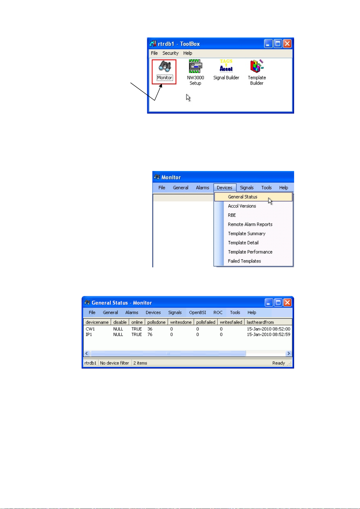
Chapter 5 – Monitoring Bristol Controllers
3. Once you are logged in, the
tools in the toolbox display.
Double-click the Monitor tool
icon to start it.
Viewing Device Status
This option allows you to view the general communication status of your devices.
When the Monitor first opens, its window is blank until you make a selection from
one of the menus.
1. To view the status of your
NW3000 or ControlWave
devices, select Devices Æ
General Status from the menu
bar.
2. The devices list with key
properties displayed.
ObjectServer for Beginners 5-2 Issued 01-10
Page 51

Chapter 5 – Monitoring Bristol Controllers
What do the General Status Values Mean?
Let’s look at these properties to see what they mean, and the kinds of values
that you should expect when your controllers are working correctly.
Online indicates the general
communication status of your
controller. TRUE means
healthy communications.
Pollsdone and pollsfailed
indicate how successful
template collection has been. If
the pollsfailed count is
increasing, you need to check
that control strategy load version
numbers match up, since this is
the most likely explanation for
this kind of behaviour.
Writesdone and writesfailed counts
indicate how well ObjectServer is
doing when writing to the controllers. If
writesfailed is increasing, you need to
The time of the last successful
communication with the
controller.
Viewing ACCOL Versions
The ACCOL Versions menu item shows discrepancies in the control strategy file
version number between the database and the device. If you find that some of the
polls are failing on one of your controllers, one of the first things you should check is
that the control strategy file version numbers match up for the controller that is
affected.
What are Control Strategy (ACCOL or 1131) File Version Numbers?
Whenever you download a modified control strategy file, it is given a new version
number in the controller.
What can happen when a new version is downloaded to a controller?
When you download a new version of the control strategy file to a controller, if you
do not update the ObjectServer database the version number in the database
conflicts with the version number in the RTU. This could cause polling to fail.
Issued 01-10 5-3 ObjectServer for Beginners
Page 52

Chapter 5 – Monitoring Bristol Controllers
1. To view control strategy file
version numbers, select
Devices Æ Accol Versions
from the Monitor menu bar.
2. The control strategy file
version numbers for each
device display.
More about Version Numbers
As we said previously, when you download a modified strategy file, it is given a
new version number within the controller.
All version numbers (signals, msd, and rtu)
should agree for each device. This is correct.
ObjectServer for Beginners 5-4 Issued 01-10
Page 53

Viewing RBE Stats
Chapter 5 – Monitoring Bristol Controllers
Here, a new version has been
downloaded to the IP1 device. The
rtu version number is now differs from
the signal and msd version numbers
for that device.
This increases the pollsfailed count
for that device. The only way we can
stop this is to update the database.
Instructions are given on how to do
this in the chapter on troubleshooting.
RBE (Report By Exception) statistics confirm that RBE is working correctly for a
device.
1. Select Devices Æ RBE.
2. RBE statistics display for each
device.
This device has no RBE signals, so
no reports are being received.
This device has RBE signals and reports are being received.
Issued 01-10 5-5 ObjectServer for Beginners
Page 54

Chapter 5 – Monitoring Bristol Controllers
Viewing Alarm Stats
You can also check that alarm signal data is being collected.
1. Select Devices Æ Remote
Alarm Reports from the menu
bar.
2. Remote alarm report statistics
display.
Viewing Template Stats
The final few options on the Device menu enable you to review the statistics for
template collection from a number of angles.
We have already seen the pollsdone and pollsfailed statistics displayed in the
General Status page, so we can look at the Template Detail view. Select Devices Æ
Template Detail from the Monitor menu bar.
ObjectServer for Beginners 5-6 Issued 01-10
Page 55

Chapter 5 – Monitoring Bristol Controllers
The scheduleid for each
template displays. Each row
signifies a single template.
The timestamps for templates
collected from a device should be
close together.
statustext for each template
should be “Collected”.
Request id numbers should
be contiguous.
Viewing Alarms
Not only can you view alarm statistics on a per device basis with the Monitor tool,
you can also view alarms.
Viewing All Alarms
Select Alarms Æ All from the menu bar.
All current alarms display
Issued 01-10 5-7 ObjectServer for Beginners
Page 56

Chapter 5 – Monitoring Bristol Controllers
Viewing Filtered Alarms
You can also filter the alarms using options on the Alarms menu.
1. You can filter the alarms
according to priority by using
the appropriate option in the
Priorities group from the
Alarms menu.
2. Or you can view
suppressed alarms by
selecting the “Suppressed”
option. Suppressed alarms
are not signals which have
their Alarm Inhibit flag set.
They are actually alarms,
but the Suppressed
property of the alarm is set
Acknowledging Alarms
You can also acknowledge alarms using the Monitor tool.
1. Right-click on an alarm’s acknowledged attribute:
2. Select the Modify Data option from the context menu.
3. Type true into the New Value field.
Check that the
field named
here is the one
you want to
modify.
Then click
OK.
4. The alarm is acknowledged. If was already cleared (as shown in the
example in step 1 above) it would disappear from the alarm list. If it was
not cleared, the acknowledged property is set to true.
You can change any value of an alarm except for the occurencetime.
ObjectServer for Beginners 5-8 Issued 01-10
Page 57

Chapter 5 – Monitoring Bristol Controllers
Viewing Signals
It is possible to view analog, digital, and string signals with the Monitor tool. Select
Signals Æ Analogs from the Monitor menu bar.
The Monitor window displays a list of all analog
signals.
Signal Filters
These are all of the filtering options on the Signals menu.
1. You can filter by signal type.We
have already mentioned the
analogs filter, but you can also
view digital or string-only signals
by selecting the appropriate
option.
2. You can view only signals which
are alarm-inhibited.
3. Disabled signals…
Issued 01-10 5-9 ObjectServer for Beginners
Page 58

Chapter 5 – Monitoring Bristol Controllers
4. Or signals that are in alarm.
Using a Device Filter
You can filter any of the views available from the Monitor tool according to the device
name.
1. Right click on the view and
select the Filter by device
name option from the context
menu.
2. If we now select the Signals
Æ Analogs menu, the signal
list content filters according
to the device filter that we
supplied. Here, only objects
from the IP1 device display.
3. We can clear the device filter
by right-clicking on any
object and selecting the
Clear filter option from the
context menu.
ObjectServer for Beginners 5-10 Issued 01-10
Page 59

Chapter 5 – Monitoring Bristol Controllers
Modifying Signal Properties
The Monitor tool allows you to monitor all signal properties except for the timestamp.
1. Right-click on the field of a
signal that you want to modify,
and then select the Modify
data option. Here we have
selected the value field.
2. The title bar on the Modify field
dialog indicates the specific
signal property you are
modifying. Type a new value
into the New Value field and
click OK.
The new value is applied.
That completes this chapter. We have demonstrated how you can use
ObjectServer’s Monitor tool to:
1. View the status of any controller
2. View and acknowledge alarms
3. View and change signal values
Note: If you encounter problems viewing your controllers or signals in the
Monitor tool, please refer to Chapter 8 – Troubleshooting.
Issued 01-10 5-11 ObjectServer for Beginners
Page 60

Chapter 5 – Monitoring Bristol Controllers
[This page is left intentionally blank]
ObjectServer for Beginners 5-12 Issued 01-10
Page 61

Chapter 6 – Basic Configuration Changes
Chapter 6 – Basic Configuration Changes
From time to time, you need to modify most process control/SCADA systems. You
may need to add or remove signals or even controllers. This chapter deals with this
process of changing things in your system so that your controllers and ObjectServer
match up every time you change something.
We see how to:
Add controllers
Remove controllers
Add signals/variables
Remove signals/variables
Add signal/variable descriptions
Change data collection rates
Change RBE data collection
Remember, for our purposes the terms
“controller”, “RTU”, and “device” are
interchangeable and all mean the same
thing.
= Controller = Device = RTU
Adding a Controller
Imagine we have created our control strategy program, downloaded it locally to the
new controller, and tested that the program works. We can now add the new
controller to our OpenBSI network. Let’s walk through the first few steps.
Issued: 01/10 6-1 ObjectServer for Beginners
Page 62
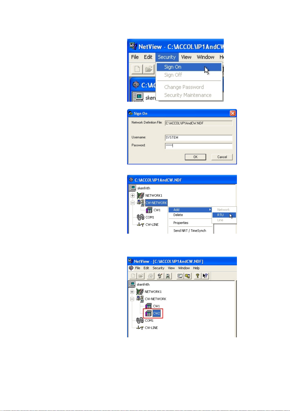
Chapter 6 – Basic Configuration Changes
Adding the New Controller to NetView
1. Log onto NetView as the
SYSTEM user. Select Security
Æ Sign On from the NetView
menu bar.
2. Sign on as the SYSTEM user.
3. Select the network for the new
RTU/controller and select Add
Æ RTU as shown here.
Configure the RTU as you
would normally. (For full
instructions on how to do this,
see the Open BSI Utilities
Manual, document# D5081).
4. Once you’ve added the new
controller to the network and the
downloaded the tested control
strategy program, it’s time to
update ObjectServer.
ObjectServer for Beginners 6-2 Issued: 01/10
Page 63
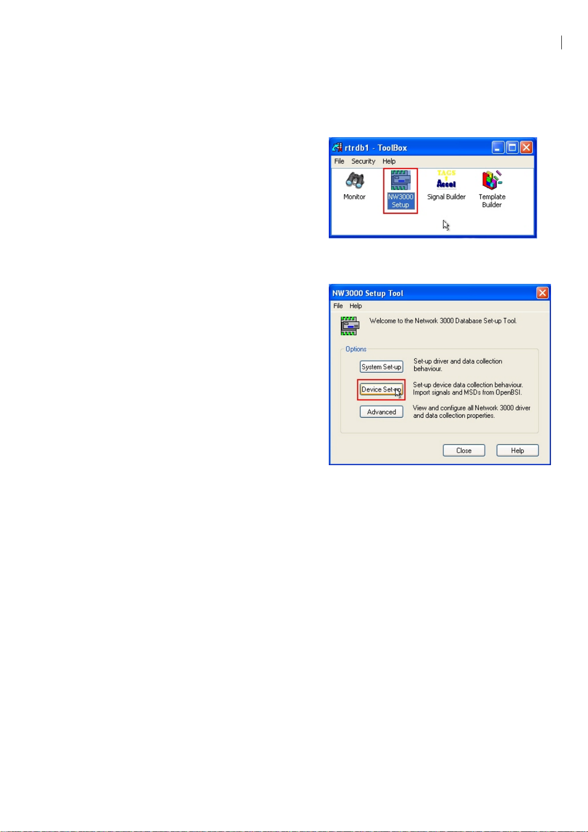
Chapter 6 – Basic Configuration Changes
Updating ObjectServer
You now need to update the ObjectServer database with the new RTU and its
signals. To do this, use the NW3000 Setup tool. This process also uses the
Database Builder and Poll List Builder tools.
1. Open up the Toolbox and log in
as the SYSTEM user.
(Instructions for doing this are in
Step3: Import Device and Signal
Information from OpenBSI
section of Chapter 4 –
ObjectServer Preparation.)
Double-click on the NW3000
Setup icon, highlighted in the
image on the right.
2. Click Device Set-up.
Issued: 01/10 6-3 ObjectServer for Beginners
Page 64

Chapter 6 – Basic Configuration Changes
3. When the Import from NetView
dialog opens the All Devices
option is selected by default.
Select the Single Device option.
Then select the new controller
that you have just added to
NetView, as shown.
Click Next>.
4. Follow the instructions in the
NW3000 Device Set-up Wizard
section in Chapter 4 to complete
the import of the new device and
its signals into ObjectServer.
When the wizard completes it opens the
Database Builder and Poll List Builder
tools and imports the new device and its
signals into the ObjectServer database.
The new controller, its signals, and its polling templates have now been added to the
ObjectServer database. ObjectServer can begin collecting data from the new device.
ObjectServer for Beginners 6-4 Issued: 01/10
Page 65

Chapter 6 – Basic Configuration Changes
Removing a Controller
Removing a controller is very similar to adding one and requires the same two
activities:
Removing the controller from NetView.
Removing the device from ObjectServer.
1. Open NetView and delete the
device that is no longer required.
2. Open the NW3000 Set-up
tool from the Toolbox and
click Advanced.
Issued: 01/10 6-5 ObjectServer for Beginners
Page 66

Chapter 6 – Basic Configuration Changes
3. When the “nw3000 Properties” dialog displays select
the “Device” tab and then select the device that has
been deleted from NetView. Then click the [Delete]
button, followed by the [OK] button.
Adding Signals/Variables
Occasionally you may need to add or remove a complete device from the controller
network. More often than not, though, you just need to add or remove signals from
existing controllers.
Note: “Signals” and “variables” are the same thing. They represent our real world
process control objects. However, this guide uses ”signal” in reference with NW3000
controllers and “variable” in reference to ControlWave devices.
ObjectServer for Beginners 6-6 Issued: 01/10
Page 67

Chapter 6 – Basic Configuration Changes
1. Create a signal using either
Workbench or ControlWave
Designer, depending on the
device. Bear in mind the rules
outlined in the Identifying and
Preparing Signals for Collection
by ObjectServer (from Chapter 3
– Controller Preparation), and
download the updated strategy
file to the controller.
Note: For details of how to download a new control strategy file to a
NW3000 or ControlWave device see the OpenBSI Utilities Manual
(Document #D5081). You can find this on the OpenBSI installation disk.
2. Open the NW3000 Set-up tool
from the Toolbox and click
Device Set-up.
3. When the “Import From
NetView” dialog displays,
select the Single Device
option and click Next>. The
wizard completes as
described in Chapter 3 and
adds the new signal to the
ObjectServer database.
Issued: 01/10 6-7 ObjectServer for Beginners
Page 68

Chapter 6 – Basic Configuration Changes
Removing Signals/Variables
To delete signals/variables, follow the same instructions as for adding a signal,
except that you need to delete the signal/variable from the control strategy program
(rather than adding it) and then download the control strategy program back to the
controller.
Use the NW3000 Set-up tool exactly as described above to remove the signal from
the ObjectServer database.
Changing Signal Descriptions from within the Load File
When you originally created the control strategy file for a controller, you may not
have included signal descriptors. Later, you can decide to provide descriptors for the
signals in the load. This process describes how to change signal descriptions and
update the ObjectServer database.
Adding Signal Descriptors
Adding descriptors to NW3000 or ControlWave signals involves two things:
1. Update the signal descriptions in the control strategy file. The exact procedure
differs for the NW3000 or ControlWave controller.
2. Run the Database Builder and Template Builder for the controller to update
the ObjectServer database.
Here are the details.
ObjectServer for Beginners 6-8 Issued: 01/10
Page 69

Chapter 6 – Basic Configuration Changes
Updating Basename Descriptors in ACCOL (NW3000 Controllers)
1. Open Workbench from NetView
by right-clicking the controller
that you want to change and
selecting RTU and Workbench
from the menus (as shown on
the right). Alternately, you can
start Workbench from the
Windows Start button.
2. Double-click Basenames
from the list of program
entities Workbench displays.
3. Type the Basenames and
Descriptors under the
Basename section. Then
build and download the file to
the controller.
For an explanation of
“basename” see An
Introduction to ACCOL
(Document #D4056).
Now follow the instructions in the section Getting Descriptor Changes into the
ObjectServer Database later in this chapter to get the new descriptors into the
database.
Issued: 01/10 6-9 ObjectServer for Beginners
Page 70

Chapter 6 – Basic Configuration Changes
Updating Variable Descriptions with ControlWave Designer (ControlWave Controllers)
This procedure outlines the process to update the signal description in ControlWave
Designer.
1. In NetView, right-click on the
controller you want to change.
Select RTU Æ ControlWave
Designer (as show on the right)
to open ControlWave Desiger.
Alternatively, you can also open
ControlWave Designer by
selecting Start Æ All Programs
Æ OpenBSI Tools Æ
ControlWave Tools Æ
ControlWave Designer.
2. Select View Æ Variable
Extension Wizard from the
ControlWave Designer menu
bar.
ObjectServer for Beginners 6-10 Issued: 01/10
Page 71

Chapter 6 – Basic Configuration Changes
3. Leave the All Variables option
selected and click OK.
4. For each signal requiring a descriptor, select that signal’s Descriptor field
and enter the descriptor:
5. Select File Æ Save then File Æ
Exit on the Variable Extension
Wizard dialog. The ControlWave
Designer screen displays. Select
Build Æ Make. Ensure that the
project compiles successfully
without errors.
6. Select Online Æ Project
Control… from the ControlWave
Designer menu bar.
Issued: 01/10 6-11 ObjectServer for Beginners
Page 72

Chapter 6 – Basic Configuration Changes
7. Sign in, if required. Then click
Download on the Project
Control dialog. The Download
dialog displays.
8. Click Download to download
the control strategy file to the
controller.
Now follow the instructions in the section Getting Descriptor changes into the
ObjectServer Database to get the new descriptors into the database.
Getting Descriptor Changes into the ObjectServer Database
Until now you have updated the ObjectServer database using the Device Set-up
wizard in the NW3000 Set-up tool. This wizard uses the Signal Builder and the
Template Builder tools to update the database. This section explains how to use
these tools directly to update the ObjectServer database.
Note: This explanation assumes you have already made changes to your control
strategy file, and tested and downloaded it the controller.
ObjectServer for Beginners 6-12 Issued: 01/10
Page 73

Chapter 6 – Basic Configuration Changes
1. Open the ObjectServer
Toolbox and double-click the
Signal Builder tool icon. The
Build Database from OpenBSI
dialog displays.
2. Select the RTU that you
changed.
3. Select the Init descriptors,
areas check box. (This is
critical!)
4. Click Build.
As the Signal Builder
updates the database,
various progress messages
display here. When the
process successfully
completes, the message
DBB completed (0 errors)
displays at the top of the
list.
When the build process
completes, click Close.
This adds the new descriptors from the control strategy file to the ObjectServer
database.
Issued: 01/10 6-13 ObjectServer for Beginners
Page 74

Chapter 6 – Basic Configuration Changes
Changing Data Collection Rates
If you used the default settings when you initially built the ObjectServer database,
you may want to change the rate at which ObjectServer collects data from
controllers. Do this using the NW3000 Setup tool.
1. Open the NW3000 Setup Tool
from the ObjectServer Toolbox
and click Advanced (highlighted
in the image on the right).
2. When the nw3000 Properties
dialog displays, select the
Device tab (to view the
collection schedule for each
device).
3. Select the controller that you
want to change from the list of
controllers.
4. Click Properties.
ObjectServer for Beginners 6-14 Issued: 01/10
Page 75

Chapter 6 – Basic Configuration Changes
5. Note the value in the Schedule
Id field for the device
(highlighted to the right). In this
example, the Schedule Id for the
device is 2. Click OK to return to
the nw3000 Properties dialog.
6. Now select the Schedules tab.
Then select the schedule for the
device that you are changing.
Click Properties.
7. Now change the polling period
for the schedule by changing the
values in the hours, minutes, or
seconds fields. You can either
type values directly into these
boxes or click d and c. In this
example, we have changed the
schedule period from one
minute to 15 seconds. When
finished, click OK on this dialog,
click OK on the nw3000
Properties dialog, and finally
click Close on the NW3000
Setup Tool dialog. Job done!
Issued: 01/10 6-15 ObjectServer for Beginners
Page 76

Chapter 6 – Basic Configuration Changes
8. Note: Schedule number
255 is the Active Polling
schedule. If an OPC
client requests a tag for a
signal, the system
automatically (but
temporarily) assigns that
signal to this schedule as
well as the one to which it
normally belongs. This
ensures faster updates
for that signal. By default,
the Active Polling
Schedule polls every 10
seconds.
Making Changes to RBE Settings
Sometimes you need to change the default RBE settings for a system. The network
may be struggling, and you may need to experimentally alter RBE settings until you
get them right.
Accessing and changing these values from ObjectServer prevents you from having
to keep changing and downloading the RBE settings in the control strategy file.
Setting the RBE Mode in Workbench (ACCOL)
Set the RBE mode in your control strategy file to zero (0) in order to change the rest
of the RBE settings on the fly from ObjectServer.
ObjectServer for Beginners 6-16 Issued: 01/10
Page 77

Chapter 6 – Basic Configuration Changes
1. Select the controller you want to
change in NetView, right-click
and select Workbench.
2. Select Task 0 from the
Workbench interface, then rightclick and select Edit Code. Task
0 has no rate, and is always
used for the RBE module.
3. Change the MODE value to zero
(0.0) as shown here.
4. Build the load and download it to
the controller.
Issued: 01/10 6-17 ObjectServer for Beginners
Page 78

Chapter 6 – Basic Configuration Changes
Setting the RBE Module in ControlWave Designer
1. Set the Active On Startup value
to TRUE.
2. Initialize the ioabInit input of the
RBE module to zero.
Updating RBE Settings in ObjectServer
1. Open the NW3000 Setup Tool
from the ObjectServer Toolbox
and select Advanced.
2. Select the Device tab and then
select the controller that has the
modified RBE module.
Then click Properties.
ObjectServer for Beginners 6-18 Issued: 01/10
Page 79

Chapter 6 – Basic Configuration Changes
On the Device dialog, set the
3.
RBE options in the RBE Data
Collection section. Click the
[Help] button the dialog for an
explanation of each option.
This chapter reviewed the processes you can use to modify your system as it grows
and changes:
Adding controllers
Removing controllers
Adding signals/variables
Removing signals/variables
Adding signal/variable descriptions
Changing data collection rates
Changing RBE data collection
Issued: 01/10 6-19 ObjectServer for Beginners
Page 80

Chapter 6 – Basic Configuration Changes
[This page is intentionally left blank.]
ObjectServer for Beginners 6-20 Issued: 01/10
Page 81

Chapter 7 – Displaying ObjectServer Data in OPC Clients
r
Chapter 7 – Displaying ObjectServer Data in OPC Clients
This chapter explains how to configure a number of OPC clients to display
ObjectServer data. OPC clients are also called HMIs, because they provide a
”human-machine interface” onto process control data.
Getting ObjectServer Real-time Data into OPC Clients on the Same Computer
In Chapter 1 of this manual we saw how the data got from the Bristol controllers into
the ObjectServer database. We can now look at how the data gets from the
ObjectServer database to the OPC client. Firstly, we see how this happens when the
client is running on the same PC as ObjectServer.
It’s really simple.
The OPC server
running on the
ObjectServer
computer serves
Bristol controller
real-time data
directly from the
database to OPC
clients in the form
of ”tags”.
ObjectServer
PC
TagBrowse
OPC Server
Database
RDI3000
ObjectServer
Open BSI
OPC clients typically
employ an OPC tag
browser to initially find
and request tags from
the OPC server.
Controller
Network
Issued: 01-10 7-1 ObjectServer for Beginners
Page 82

Chapter 7 – Displaying ObjectServer Data in OPC Clients
Help – What’s a Tag?
At the most basic level, a “tag” is a
label that identifies an object. For
instance, we tie labels to our luggage
when we go on holiday so that if the
luggage gets lost, the airport people
can identify it as ours.
According to the dictionary, a tag can also be described as:-
a. A label assigned to identify data in a computer’s memory.
b. A sequence of characters in a markup language used to provide information, such
as formatting specifications, about a document.
These definitions belong to the disciplines of computer programming and web
development respectively.
However, these definitions are also useful in describing what an OPC tag is.
DEFINITION: An OPC tag can be seen as a coded label that describes a single
property of an object (= signal = variable) within an OPC server’s object store.
One Tank
Objects and ObjectServer
As we said in Chapter 1 of this manual, on a very basic
level, the objects stored in ObjectServer are pumps,
tanks, valves, and so on.
However, process control systems are more interested in
the state of each object in the system. We obtain this
data by attaching sensors to the objects, which send
signals to our RTU. A simple valve only requires one
sensor to indicate that it is open or closed. However, we
may need more than one sensor to understand the state
of other objects.
For instance, we may need to know the level,
temperature, and pressure of fluid inside a tank. We
attach sensors to the tank that signal these
measurements to the RTU. In effect, each of these three
sensors is represented in the database as a separate
signal object, but they reference the same physical object
Three Sensors
Level
Temperature
Pressure
Three signals
ObjectServer for Beginners 7-2 Issued: 01-10
Page 83

Chapter 7 – Displaying ObjectServer Data in OPC Clients
How do OPC Servers Define Signal Data?
We have established that the objects in our ObjectServer process control
system are more correctly understood as sensors that are attached to actual
physical objects. Because sensors communicate via electronic signals, they are
known as “signals” to ObjectServer.
Each signal has a value. Our TANK1.LEVEL. signal is the height of fluid in our
tank, the TANK1.PRES. signal is the pressure in the tank, and TANK1.TEMP.
signal is the temperature in the tank.
But besides value, each signal also has a number of other properties. These
can be its name (TANK1.LEVEL.) which distinguishes it from other signals and
its units property (such as metres) which tells us the units in which its value is
measured.
In fact, non-alarm Bristol controller signals have a total of seven properties the
ObjectServer OPC server can expose: name, value, description, units,
questionable, controlinhibit, and manualinhibit. Bristol alarm signals have
11 additional properties, relating to their alarm status. The OPC Server makes
each property of each signal available to our OPC client as an OPC tag. So
what is an OPC tag again?
An OPC Tag is a Query
OPC clients display OPC data by requesting the data from OPC servers in the form
of an OPC tag. So, an OPC tag is actually a type of query.
Databases enable us to get at the data they store by permitting us to query that data.
Query methods have evolved with the needs of applications. Following are three
examples of how query methods are employed for different purposes.
The first of the three example query methods applies to a flat file database in the
form of an address book. This query method returns data as collections of records
starting with the same letter.
The second example method queries a relational database as the rows and columns
of a table. The third example method shows how OPC tags return the value of a
single attribute to the OPC client, for display as a shape or text object.
The objects ObjectServed serves are actually single properties of objects that are
visualized as drawn objects on a display. Each OPC tag on the client requests a
single property or attribute of a signal in our database.
Issued: 01-10 7-3 ObjectServer for Beginners
Page 84

Chapter 7 – Displaying ObjectServer Data in OPC Clients
Alphabetical Query
The simplest of databases is an address
book. This type of database is known as
a flat file database. It has only one table.
We query this kind of database by
grouping the entries alphabetically. This
kind of query enables us to find what we
want in two steps:-
1. We find a group of records which
begins with the same letter
2. We search down these records to
find the exact one we want.
This kind of query returns a record object
with all of its attributes (such as a name,
an address, or a phone number).
SQL Query
Relational databases make queries
a much more complex task, so
complex in fact that it requires a
language to formulate the query.
This language is called Structured
Query Language (SQL).
SQL enables us to search for one
or more attributes of one or more
objects in one or more tables.
The example on the left shows an
SQL query sent to the ObjectServer
database using the SQL client. The
results of an SQL query are always
shown as a table with rows and
columns.
In this type of query, an “ object” is
understood to be a single row from
the returned table. Each row in our
example displays three properties
for each object (signal).
ObjectServer for Beginners 7-4 Issued: 01-10
Page 85

Chapter 7 – Displaying ObjectServer Data in OPC Clients
Object Query
OPC Data Access clients display objects visually as shapes or text. Display
objects can be static or dynamic. Each dynamic visual object is linked to the value
of single attribute in the database. The “object: that ObjectServer serves up here
is actually a single attribute (not a row) from the ObjectServer database.
For each OPC tag registered by the client display, the OPC server sends an
Object Query (which requests a single attribute) from the ObjectServer database.
The value requested is updated on the Client display every few seconds.
The OPC tag associated with this text object returns the
name of the signal.
The OPC tag associated with this dynamically
sized object returns the value of the signal.
Preparation
Before you attempt to configure any OPC client HMI to display ObjectServer data,
you must make sure that ObjectServer is running and collecting data from your
controllers. You can also start the OPC server manually, but the OPC client should
do this for you if you don’t. Select Start Æ Run, then type BristolOPCServer.exe
into the Open field, and click OK..
Issued: 01-10 7-5 ObjectServer for Beginners
Page 86

Chapter 7 – Displaying ObjectServer Data in OPC Clients
Getting ObjectServer Real-time Data into Genesis32™
Genesis32 is an OPC data access client application developed by ICONICS, Inc.
Here’s how to get ObjectServer data into a GraphWorX™32 display (GraphWorX32
is the display tool included within Genesis32).
What follows is not a detailed description of how to use every feature of
GraphWorX32. It is intended only as an example to show how to get tags
from the ObjectServer OPC server into GraphWorX32. Please use the online
help provided with GraphWorX32 for information on any other feature.
We are going to display a tank level on our display as a rectangle, so that the height
of the rectangle represents the value of the signal. You can use any real analog
signal having a value that fluctuates between a defined maximum and minimum
value.
NOTE
1. First, we open
GraphWorX32 and
select the rectangle
tool
2. Then we click on the
display area, and create
the rectangle. We now
have a visible rectangle
object, but it is not yet
connected through OPC
with our signal value. To
do this, we need to
make this into a
dynamic object.
Drag the mouse in
this direction
ObjectServer for Beginners 7-6 Issued: 01-10
Page 87

Chapter 7 – Displaying ObjectServer Data in OPC Clients
3. With the rectangle
still selected, select
Dynamics Æ
Actions Æ Size
from the menu bar.
You could also click
on the Size dynamic
button on the
dynamic toolbar.
4. The rectangle’s
Property Inspector
dialog displays
with the new Size
tab added, and the
cursor inside the
Data Source box.
We can now
browse for Tags by
clicking Data
Tags.
Issued: 01-10 7-7 ObjectServer for Beginners
Page 88

Chapter 7 – Displaying ObjectServer Data in OPC Clients
5. The ICONICS Unified
Data Browser
searches for the
available OPC
servers. We can see
two ObjectServer
OPC servers outlined
in red.
Make sure you select
the right OPC Server.
You need real-time
data, not alarm/event
data.
Double-click on the
BristolBabcock.BristolOPCServer
6. Now, in the left pane,
click the plus sign to
the left of the “rtrdb1”
folder. This folder
represents the whole
ObjectServer
Database
We are drilling down
to get at the tag we
want.
ObjectServer for Beginners 7-8 Issued: 01-10
Page 89

Chapter 7 – Displaying ObjectServer Data in OPC Clients
7. Now we can see
the available
controllers . In
the right pane
double-click
controller that
contains the
signal you want.
In this example
we double-click
controller ‘CW1’.
8. We can now see
lots of signals
that belong to the
controller. We
need to find the
signal we are
after, and then
double click on it.
For this example,
we use
TANK1_LEVEL.
Issued: 01-10 7-9 ObjectServer for Beginners
Page 90
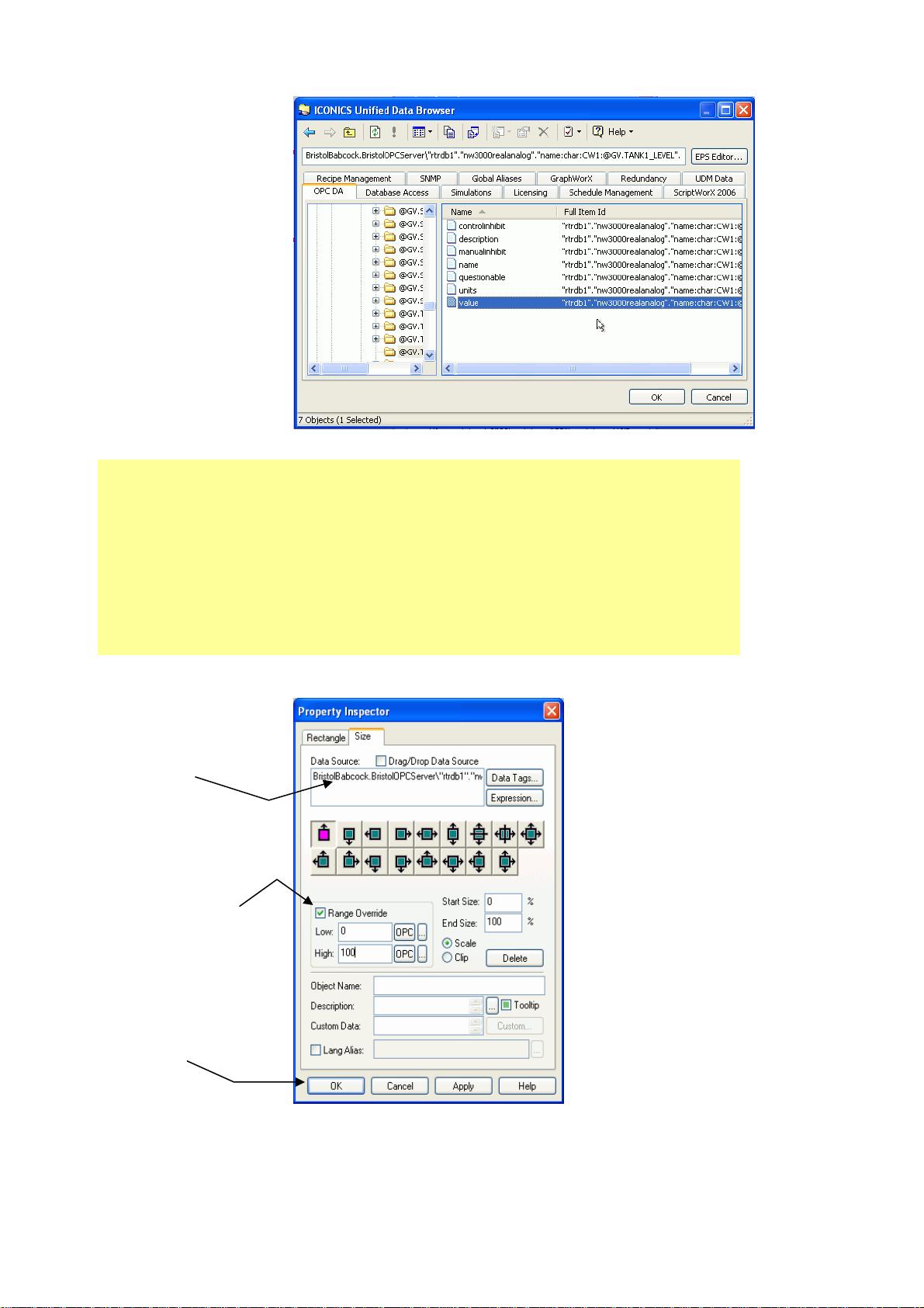
Chapter 7 – Displaying ObjectServer Data in OPC Clients
9. This exposes the
individual tags for
the signal we want.
Select the ‘value’
tag, then click OK.
This re-displays the
Property Inspector
dialog.
Why do Different Signals Have Different Tags?
The OPC server serves different OPC tags depending on the signal type.
Tags for Bristol controller non-alarm realanalog signals include
controlinhibit, manualinhibit, description, name, questionable, units, and
value. Realanalog alarm signals use all of these plus highlimit and
lowlimit tags.
Note: The tag is
automatically written
into the Data Source
field.
10. Select the
Range Override
check box and
enter in the Low
and High values
for the signal
value. Then click
OK.
ObjectServer for Beginners 7-10 Issued: 01-10
Page 91

Chapter 7 – Displaying ObjectServer Data in OPC Clients
More about OPC Tags
An OPC tag is a string that enables the OPC server to serve object values that
OPC clients request.
The actual format of the OPC tag used differs between OPC servers, but the
format is typically <OPCServerProgID>\<OPCItem>. The <OPCServerProgID>
portion of the tag is always present, followed by a backslash delimiter (\). The
OPC Item part of the tag defines an object property. The number of elements in
the part of the tag that defines the OPC Item may differ widely for each OPC
server. For instance, an ObjectServer OPC Item includes the data-service, table
name, signal name, and signal property. You delimit each part of this section of
the tag with a period.
An Example ObjectServer OPC Tag
Here’s an example ObjectServer OPC tag. Labels on each part of the tag explain
what that part identifies. Once you know the tag structure, you can use this
information to copy and modify tags textually rather than having to use the tag
browser every time.
OPC Server ID
11. Back on the
display page, we
can see that the
selected rectangle
,has red dots
around it. These,
signify that it is a
dynamic object,
now associated
with an OPC tag
value.
We need to put the
display into
Runtime mode to
see the dynamic
object in action.
Select the Runtime
menu option,
highlighted here.
Data
Service
Table
(Signal Type)
Object ID
Object Property
And Data Type
Issued: 01-10 7-11 ObjectServer for Beginners
Page 92

Chapter 7 – Displaying ObjectServer Data in OPC Clients
12. In Runtime mode, the rectangle’s height adjusts to represent the value of
the tag that we have associated it with. If we hold the mouse over the
rectangle a tooltip displays the tag and its value.
That’s all there is to it. The OPC server is now serving ObjectServer data to the
GraphWorX OPC client and displaying it on the page.
TIP – Copy, Paste and Change the Tag
Once you have retrieved one OPC tag in this way, there is no need to go
through this whole process again. You can copy, paste and change the
original OPC tag into the Data Source field for any dynamic object to display
any tag you like on the HMI display.
Using ObjectServer with Legacy GraphWorX™ HMIs
HMI systems created to view NW3000 and ControlWave controller data before the
introduction of ObjectServer used the ICONICS OPC Server (also known as the
OpenBSI OPC Server).
The ICONICS OPC server used a different tag format to the one ObjectServer uses,
but the ObjectServer OPC Server can be set to read the old tag format simply by
running the 'IconicsOPCServerReplace.cmd' file found in the ObjectServer bin
folder (the default location is 'C:\OpenBSI\ObjectServer\bin').
Now the ObjectServer OPC server can register and serve OpenBSI OPC tags. This
action can be reversed at any time by running the 'IconicsOPCServerRestore.cmd'
file from the same directory.
ObjectServer for Beginners 7-12 Issued: 01-10
Page 93

Chapter 7 – Displaying ObjectServer Data in OPC Clients
Modifying a Tag in GraphWorX
If we want to display the name of the signal above the Tank Level, using a Process
Point, this is what we can do:-
1. Copy the tag from the Size
tab’s Data Source field.
2. Create a Process
Point by selecting the
Dynamics Æ
Intrinsics Æ Process
Point option from the
menu bar, as shown
here. A Process Point
displays a tag as text.
3. Click on the display area
where you want the Process
Point to appear and then
paste the copied tag into the
Process Point’s Data Source
field.
Issued: 01-10 7-13 ObjectServer for Beginners
Page 94
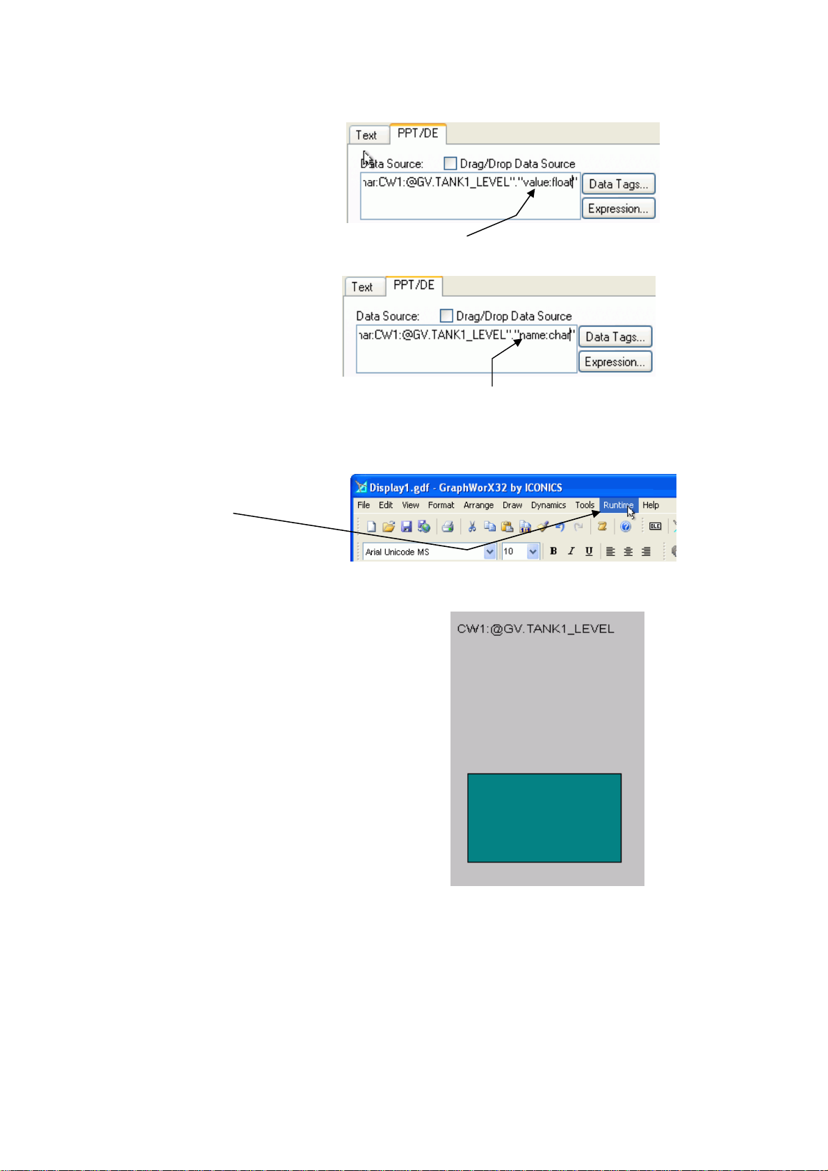
Chapter 7 – Displaying ObjectServer Data in OPC Clients
4. Change the object property
of the tag to be the name.
You have to specify the
data type of the attribute, so
change “value:float” to
“name:char”. Retain the
paired quotation marks! The
Delete the “value:float” property.
name is a string or
character data type (“char”
for short).
Type in the new “name:char”
property. Keep the double quotes.
5. Close the Property Inspector
dialog and put the display into
Runtime mode.
6. The signal name is now
displays above the rectangular
level display.
We have used a Process Point
to display the tag as text. We
have modified the text of the
original “value” tag to display
the “name” tag instead.
You should now be able to get ObjectServer data into the Genesis32 HMI application
via the OPC Server.
ObjectServer for Beginners 7-14 Issued: 01-10
Page 95

Chapter 7 – Displaying ObjectServer Data in OPC Clients
y
Getting ObjectServer Real-time Data into InTouch®
Sold by Wonderware®, InTouch is an HMI software package that includes an OPC
client, so it can display data from OPC servers. This section shows how to get
ObjectServer data into an InTouch window that is running on the same computer as
ObjectServer.
NOTE
What follows is not a detailed description of how to use every feature of
InTouch. It is intended only as an example to show how to get tags from the
ObjectServer OPC server into InTouch. Please use the online help provided
with InTouch for information on an
1. You must first install the
OPCLink I/O Server in
order to view data from
the ObjectServer OPC
Server with InTouch.
After installing InTouch,
place the I/O Servers
disk into the CD/DVD
Drive and click the ‘IO
Servers option.
other feature.
2. Select the OPCLink
option from the list of I/O
Servers. Then click Next>
and finish the installation
wizard.
Issued: 01-10 7-15 ObjectServer for Beginners
Page 96

Chapter 7 – Displaying ObjectServer Data in OPC Clients
We now need to configure OPCLink to connect to the ObjectServer OPC
server. We can then set up an OPC Path for the OPC Server, so the client can
request tags based on that path.
3. Start the OPC Link
application. Click Start Æ
All Programs Æ
Wonderware
FactorySuite Æ IO
Servers Æ OPCLink.
The user interface
displays.
4. In OPCLink, a topic
contains the necessary
configuration for a group of
tags used in an InTouch
window (display). Select
Configure Æ Topic
Definition.
5. Click New on the Topic Definition
dialog, and then configure a new
Topic.
Type a name for the topic here. The name can be any text you want, so
be descriptive to remind yourself of what the topic does. In this example
we want to be able find all analog tags from the CW1 device, so the topic
name (CW1ANALOGS) should reflect this.
Select the
BristolBabcock.BristolOPCServer
object from the list of OPC Servers.
Click Browse next to the OPC
Server Name field to browse
for tags using the selected
OPC server.
ObjectServer for Beginners 7-16 Issued: 01-10
Page 97

Chapter 7 – Displaying ObjectServer Data in OPC Clients
6. From the OPC Browser
interface, go through the tag
hierarchy and select any
realanalog signal. Then click
OK.
Why Don’t You Select a Specific Tag?
We don’t select a specific tag because a Topic Definition is more useful if we can
use it to select multiple tags. We are going to use the first part of the OPC tag
string to define a path that exposes all the analog signals that are within a
selected Bristol controller. Below is a fully qualified ObjectServer OPC tag.
Data
Service
OPC Server ID
We are going to use this part of the
tag as an OPC path in InTouch.
Table
(Signal Type)
Object ID
Object Property
And Data Type
Then we can define this part of
the tag ourselves when creating
InTouch windows (displays). We
can use the OPC Browser
interface to search for the exact
tag we want, and then copy this
last part of the tag into the Item
field on the Tagname Dictionary
dialog (see step 17 below).
Issued: 01-10 7-17 ObjectServer for Beginners
Page 98

Chapter 7 – Displaying ObjectServer Data in OPC Clients
7. If you see this warning
dialog, just click OK. We will
be adjusting the OPC path
manually in the next step.
8. Back on the OPC Link Topic
Definition dialog, we need to
modify the OPC Path. The
modified path name ensures
that we can specify any
realanalog tag within the
InTouch Tag Dictionary.
Delete the part of the tag from after the
second period to the end of the tag, as
shown here. Do not include the second
period in the selection
When you have made this
modification click OK.
The OPC Path should now read
“rtrdb1”.”nw3000realanalog”.
ObjectServer for Beginners 7-18 Issued: 01-10
Page 99

Chapter 7 – Displaying ObjectServer Data in OPC Clients
9. Now start InTouch WindowMaker
by selecting Start Æ All Programs
Æ Wonderware FactorySuite Æ
InTouch WindowMaker. Then
select File Æ New Window… to
create a new window. In this
example, we will name this window
”Tank1 Level”.
10. We have re-sized the window and
created a rectangle with a blue
background To represent the level
in Tank1. We now need to
animate this visual object and
control its height by the value of
the Tank1.Level tag in the
ObjectServer OPC server.
To do this, we need to know the
ObjectServer OPC tag format and
the names of the signals in the
Bristol Controller load.
11. We now need to create a new tag
in the InTouch ‘Tag Dictionary’
that links to the topic we created
in OPCLink and uses its path to
form the tag for the Tank1 Level
value.
Select Special Æ Tagname
Dictionary from the InTouch
WindowMaker menu bar.
Issued: 01-10 7-19 ObjectServer for Beginners
Page 100

Chapter 7 – Displaying ObjectServer Data in OPC Clients
12. Click New on the ‘Tagname
Dictionary’ dialog to create a
new tag definition.
13. Click Type.
14. Select IO Real check box
from the Tag Types dialog.
Click OK.
15. A new section appears at the
bottom of the Tagname
Dictionary dialog. We need
to create an Access Name,
so click Access Name.
ObjectServer for Beginners 7-20 Issued: 01-10
 Loading...