

Micro Motion Coriolis Interface Module User Manual (for ROC800-Series and FloBoss 107 Flow Managers)
Table of contents
 Loading...
Remote Automation Solutions Micro Motion Coriolis Interface Module User Manual (for ROC800-Series and FloBoss 107 Flow Managers) Manuals & Guides
Page 1

Part D301753X012
May 2016
Micro Motion® Coriolis Interface Module
User Manual (for ROC800-Series and FloBoss
107 Controllers)
™
Remote Automation Solutions
Page 2

Micro Motion Coriolis Interface Module User Manual (for ROC800-Series and FloBoss 107)
Page
Revision
All pages
May-2016
All pages
August-2015
All pages
May-2015
Initial release
February-2014
Revision Tracking Sheet
May 2016
This manual may be revised periodically to incorporate new or updated information. The revision date of each
page appears at the bottom of the page opposite the page number. A change in revision date to any page also
changes the date of the manual that appears on the front cover. Listed below is the revision date of each page (if
applicable):
ii Revised May-2016
Page 3

Micro Motion Coriolis Interface Module User Manual (for ROC800-Series and FloBoss 107)
Contents
Chapter 1 – Introduction 1
1.1 Scope and Organization ................................................................................................................. 1
1.2 Product Overview ........................................................................................................................... 2
1.3 Program Requirements .................................................................................................................. 3
Chapter 2 – Installation 5
2.1 Installing the Module ....................................................................................................................... 5
2.2 Wiring the Module ........................................................................................................................... 5
2.3
MPU Loading Threshold (ROC800) ............................................................................................... 8
Chapter 3 – Configuration 9
3.1 Coriolis Setup and Values Screen ................................................................................................ 10
3.1.1 Coriolis Setup and Values – General Tab ..................................................................... 12
3.1.2 Coriolis Setup and Values – Calibration Tab ................................................................. 15
3.1.3 Coriolis Setup and Values – Diagnostics Tab ................................................................ 17
3.1.4 Coriolis Setup and Values – Smart Meter Verification ................................................... 20
3.1.5 Coriolis Setup and Values – TBR/TMR ......................................................................... 22
3.1.6 Coriolis Setup and Values – Meter Zero ........................................................................ 25
3.1.7 Coriolis Setup and Values – Units Configuration ........................................................... 27
3.1.8 Coriolis Setup and Values – Values .............................................................................. 28
3.1.9 Coriolis Setup and Values – Current Dump Cycle ......................................................... 33
3.1.10 Coriolis Setup and Values – Dump Cycle Min/Max Data .............................................. 35
3.1.11 Coriolis Setup and Values – PVR .................................................................................. 38
3.2 Saving the Configuration .............................................................................................................. 40
Chapter 4 – Reference 43
4.1 Point Type 65/244: Micro Motion Coriolis Interface Module ......................................................... 44
Revised May-2016 iii
Page 4

Micro Motion Coriolis Interface Module User Manual (for ROC800-Series and FloBoss 107)
[This page is intentionally left blank.]
iv Revised May-2016
Page 5

Micro Motion Coriolis Interface Module User Manual (for ROC800-Series and FloBoss 107)
Chapter 1 – Introduction
Caution
When using inputs that are not resident in the flow computer or RTU (that is,
are provided by a communication mechanism) for control, ensure that a
supervisory system or mechanical safety equipment is in place to provide
proper function. While communication errors are noted in the device’s alarm
log, be aware that you may need to perform actions to prevent field issues.
This chapter describes the structure of this manual and presents an
overview of the Micro Motion® Coriolis Interface module for the
FloBoss 107 Flow Manager (FB107) and the ROC800-Series Remote
Operations Controller (both the ROC800 and the ROC800L). The
Coriolis Interface module provides all of the functions necessary to
communicate with the core processor of a Micro Motion Coriolis meter
and includes an onboard RS-485 communications port that enables
communications between the module and the Coriolis meter without
using one of the communications ports of the FB107 or the
ROC800/ROC800L.
Additionally, in simple allocation situations which do not require
custody transfer, one Coriolis Interface module (which connects with up
to six Coriolis meters) can take the place of transmitters. In situations
requiring custody transfer and the pulse counts transmitters provide,
connecting the Coriolis Interface module to the transmitter provides
extensive real-time analysis of flow data.
APP 485 application modules for the ROC800/ROC800L and FB107
(including the Micro Motion Coriolis Interface module) streamline the
installation process by automatically installing all point types and
screens that are part of the application. APP 485 modules can house a
variety of applications; for further information about additional APP
485 modules, contact your sales representative.
1.1 Scope and Organization
This document serves as the user manual for the Micro Motion Coriolis
Interface Module, which is intended for use in a FB107 or
ROC800/ROC800L. This manual describes how to install and configure
the Coriolis Interface module (referred to as the “Coriolis Interface” or
“the module” throughout the rest of this manual). You access and
configure this module using ROCLINK 800 configuration software
loaded on a personal computer running Microsoft® Windows 2000
(with Service Pack 2), Windows XP, Windows Vista, or Windows 7.
The sections in this manual provide information in a sequence
appropriate for first-time users. Once you become familiar with the
procedures and the software, the manual becomes a reference tool.
This manual has the following major sections:
Revised May-2016 Introduction 1
Page 6

Micro Motion Coriolis Interface Module User Manual (for ROC800-Series and FloBoss 107)
Chapter 1 – Introduction
Chapter 2 – Installation
Chapter 3 – Configuration
Chapter 4 – Reference
This manual assumes that you are familiar with the FB107 and the
ROC800/ROC800L and its configuration. For more information, refer
to the following manuals:
FloBoss™ 107 Flow Manager Instruction Manual (part
D301232X012).
ROC800-Series Remote Operations Controller Instruction Manual
(part D301217X012).
ROCLINK™ 800 Configuration Software User Manual (for
FloBoss™ 107) (part D301249X012).
ROCLINK™ 800 Configuration Software User Manual (for
ROC800-Series) (part D301250X012).
ROCLINK™ 800 Configuration Software User Manual (for
ROC800L) (part D301246X012).
1.2 Product Overview
The MMI Coriolis Interface module enables the FB107 or the
ROC800/ROC800L to communicate directly with the core processor in
up to 6 (4 on the FB107) Micro Motion Coriolis meters on the same
EIA-485 (RS-485) communications port. (The module provides its own
communications port for this purpose.) The module serves as an
interface between Coriolis meters, transmitters, and the FB107 or
ROC800/ROC800L, retrieving, validating, and then processing the data.
By supporting multiple core processors or transmitters at one time, the
module eliminates the need to have one transmitter for each core
processor. Additionally, it removes the need for a water cut probe in a 2phase separator for liquid output. Finally, it manages transient mist
remediation (TMR), transient bubble remediation (TBR), production
value reconciliation (PVR), meter zeroing, and Smart Meter
Verification (provided these functions are activated on the Coriolis
meter’s core processor).
The module operates in either continuous mode (during which flow
never ceases) or dump cycle mode (during which, should flow drop
below a minimum setpoint, the module stops accumulating flow, counts
cycles, and stores cycle-specific data).
Using Modbus, the module continuously requests data from the meters.
When it receives new data, the module compares the volume flow rate
from the meter to the user-defined volume low flow cutoff value and
performs the following actions:
If the value of the volume flow rate register is zero, the
parameters in the module’s point type corresponding to the values
2 Introduction Revised May-2016
Page 7

Micro Motion Coriolis Interface Module User Manual (for ROC800-Series and FloBoss 107)
received from the meter are updated, and no further processing of
the data is performed.
If the value is greater than zero but less than the volume low
flow cutoff value, the module considers the volume and mass
accumulated to be trickle flow. The accumulated volume and mass
values are added to both the daily totals parameters and the separate
trickle flow totals.
If the value of volume flow rate is greater than the module’s low
flow cutoff value, the module considers the values received during
the period at which the volume flow rate remains above the volume
low flow cutoff value to be part of a dump cycle. The module keeps
track of the total volume and mass accumulated during a dump
cycle, and updates the volume and mass totals once the dump cycle
has ended. The maximum and minimum density and drive gain
values that occurred during the dump cycle are also determined.
The module uses the contract hour you define using ROCLINK 800 to
determine when a new contract day has begun. The module stores the
maximum and minimum density and drive gain values, the number of
dump cycles, and the volume and mass accumulators for the current and
previous contract days. When a new contract day is reached, the module
saves the values for the current contract day as the previous day values,
and then resets the current day values. The module also records monthly
totals for volume, mass, and the number of dump cycles. The module
zeroes totals at the beginning of a new month, which occurs on the
contract hour of the first day of a new month.
Note: The totals shown on the Values tab are based on the specified
contract hour. These totals are independent from the Force End
of Day selection (ROC > Information), and are not updated
when you perform a Force End of Day.
The continuous mode is designed to measure gas or liquid flow when
the flow is not coming from a separator monitoring system. In this mode
the module continuously requests data from the meters, retrieving and
saving values for Total Volume for Today, Yesterday Total Volume,
Yesterday's, Monthly and the accumulated value since the last reset. The
module retrieves and saves mass values for the same periods.
Note: In case of a communications failure, the module is set to “hold
last value.”
1.3 Program Requirements
The Micro Motion Coriolis Interface module is compatible with version
1.70 (or greater) of the FB107 firmware, with version 3.61 (or greater)
of the ROC800 firmware, with version 1.41 (or greater) of the
ROC800L firmware, and with version 2.40 (or greater) of the
ROCLINK 800 configuration software.
Revised May-2016 Introduction 3
Page 8

Micro Motion Coriolis Interface Module User Manual (for ROC800-Series and FloBoss 107)
Device Type
Firmware Version
If used in conjunction with user programs, the Micro Motion Coriolis
Interface module works with version 1.02 (or greater) of the Linear
Meter Flow Calculation program.
The Coriolis Interface module supports the following firmware versions
of these core processors and transmitters:
700 Core Processors V3.42 or greater
800 Enhanced Core Processor V4.14 or greater
1500 Transmitter V6.6 or greater
1700 Transmitter V6.6 or greater
2500 Transmitter V6.6 or greater
2700 Transmitter V6.6 or greater
3000-Series Transmitter V8.40 or greater
Note: The comm settings for the Interface module are fixed at a baud
rate of 19,200, no parity, 8 data bits, and 1 stop bit. You cannot
change these values; the meter’s core processor detects this
protocol and matches them automatically. However, if you are
using transmitters, you must use Micro Motion’s ProLink®
software to change the comm settings on those transmitters to
match these settings.
4 Introduction Revised May-2016
Page 9

Micro Motion Coriolis Interface Module User Manual (for ROC800-Series and FloBoss 107)
General Procedure
Installation requires that you perform a number of steps in a specific
Chapter 2 – Installation
This chapter provides instructions for installing the Coriolis Interface
module. Read Section 1.3 of this manual for program requirements. The
FB107 and the ROC800/ROC800L each support only one Coriolis
Interface module.
Note: The FB107 can support only one APP 485 module. If you
already have an APP 485-based application in your FB107,
consider which application is most appropriate for your needs.
sequence:
1. Power down the FB107 or ROC800/ROC800L.
2. Install the application module (refer to Section 2.1).
3. Wire the module (refer to Section 2.2).
4. Power up the FB107 or ROC800/ROC800L.
5. Configure the module (refer to Chapter 3).
2.1 Installing the Module
The application module occupies the standard footprint of an FB107 or
ROC800/ROC800L I/O or communications module. Place the module
in any empty slot on the ROC800/ROC800L or FB107.
To ensure that the device recognizes the module, you must perform a
warm start (ROC > Flags > Warm Start).
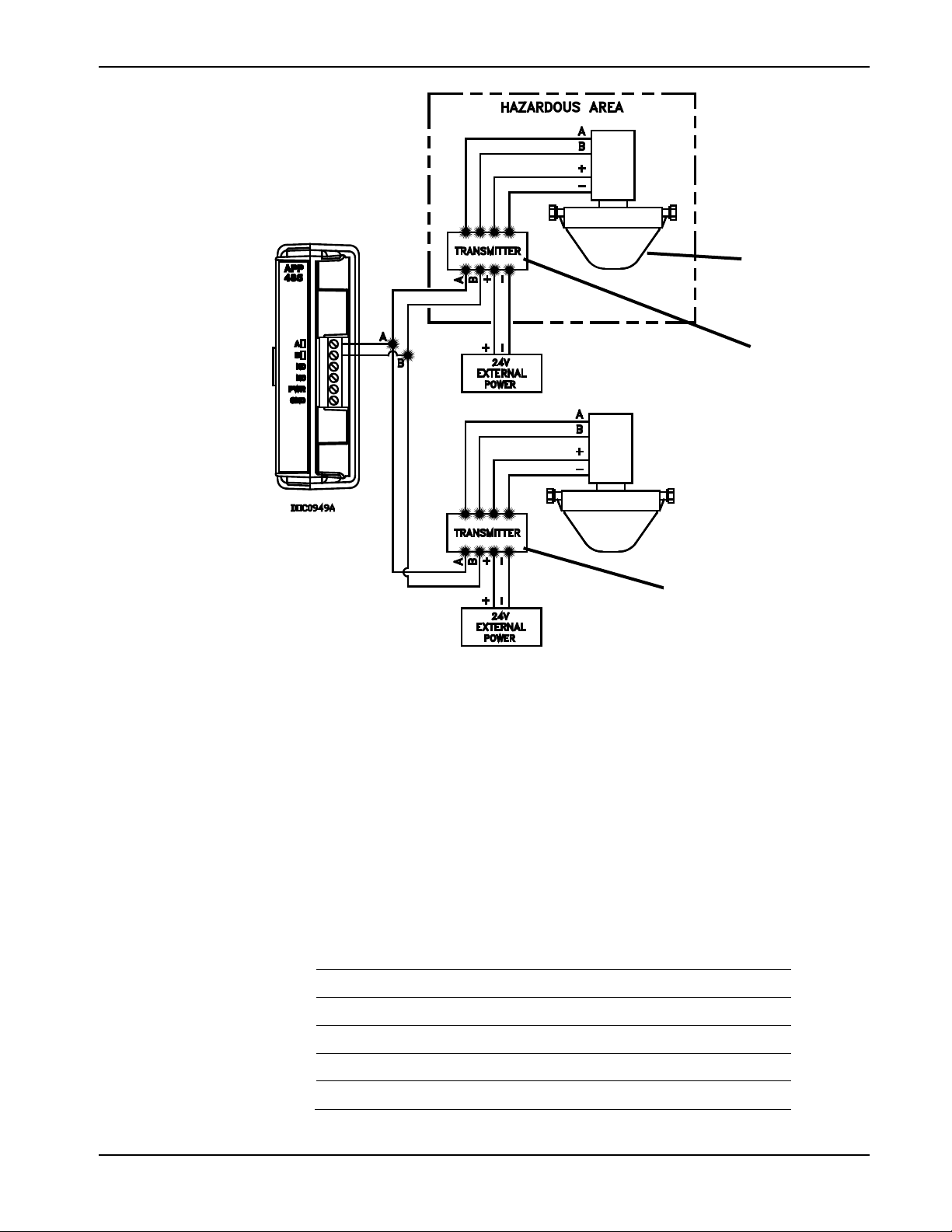
2.2 Wiring the Module
Connect the Coriolis meter(s) to the communications port on the module
using between 16 and 24 AWG wiring. Figure 1 and Figure 2 show
example wiring between the module and several meters.
Note: Coriolis meters must be externally powered.
Revised May-2016 Reference 5
Page 10

Micro Motion Coriolis Interface Module User Manual (for ROC800-Series and FloBoss 107)
A
Micro Motion 700/800 Coriolis Meter with Internal Core Processor
B
Micro Motion MVD Direct Connect™ Safety Barrier
B
A
Figure 1. Module Wiring
6 Configuration Revised May-2016
Page 11
Micro Motion Coriolis Interface Module User Manual (for ROC800-Series and FloBoss 107)
A
Micro Motion 700/800 Coriolis Meter with Internal Core Processor
B
Micro Motion 1700 (single variable), 2700 (multi-variable), or 3000-Series
transmitter suited for use in a hazardous area
C
Micro Motion 1500 (single variable), 2500 (multi-variable), or 3000-Series
transmitter suited for used in a non-hazardous area.
A
B
C
Figure 2. Module Wiring
For best results, all Micro Motion Coriolis meter and transmitters
require 24Vdc power. The following table outlines the typical power
draw for standard Coriolis meter configurations. When designing an
application, consider these power requirements.
Table 1. Configuration Power Requirements
Configuration 24 VDC Current
Sensor with Core Processor Only 768 mW 32 mA
Sensor with Core Processor & Barrier 1440 mW 60 mA
Sensor with 1500-2500 Transmitter 3432 mW 143 mA
Sensor with 1700-2700 Transmitter 6000 mW 250 mA
Sensor with 3700 Net Oil Transmitter 7420 mW 309 mA
Revised May-2016 Configuration 7
Page 12
Micro Motion Coriolis Interface Module User Manual (for ROC800-Series and FloBoss 107)
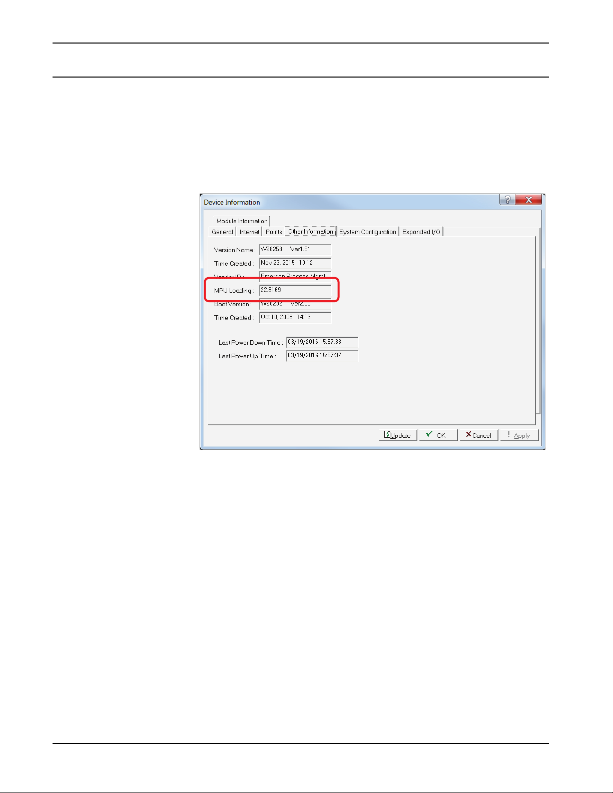
2.3 MPU Loading Threshold (ROC800)
To maximize the performance of your ROC800 device, always verify
the performance of specific application combinations before using them
in the field to ensure the MPU load typically remains below 85% with
peak MPU loading levels below 95%.
To check the current MPU load at any time, select ROC > Information
> Other Information and review the value in the MPU loading field.
Figure 3. MPU Loading
8 Configuration Revised May-2016
Page 13
Micro Motion Coriolis Interface Module User Manual (for ROC800-Series and FloBoss 107)
Chapter 3 – Configuration
After you have successfully installed the MMI Coriolis Interface
module and wired the meter to the module, start ROCLINK 800 and
configure the module using the Coriolis Setup and Values screen (see
Section 3.1). Use the screen – and its component tabs – to configure
communications with the Coriolis meter, perform calibration, view flow
rates and totals, and view diagnostic information.
To ensure that the device recognizes the module, you must perform a
warm start (ROC > Flags > Warm Start).
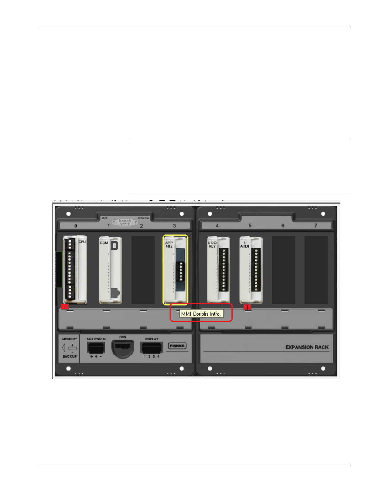
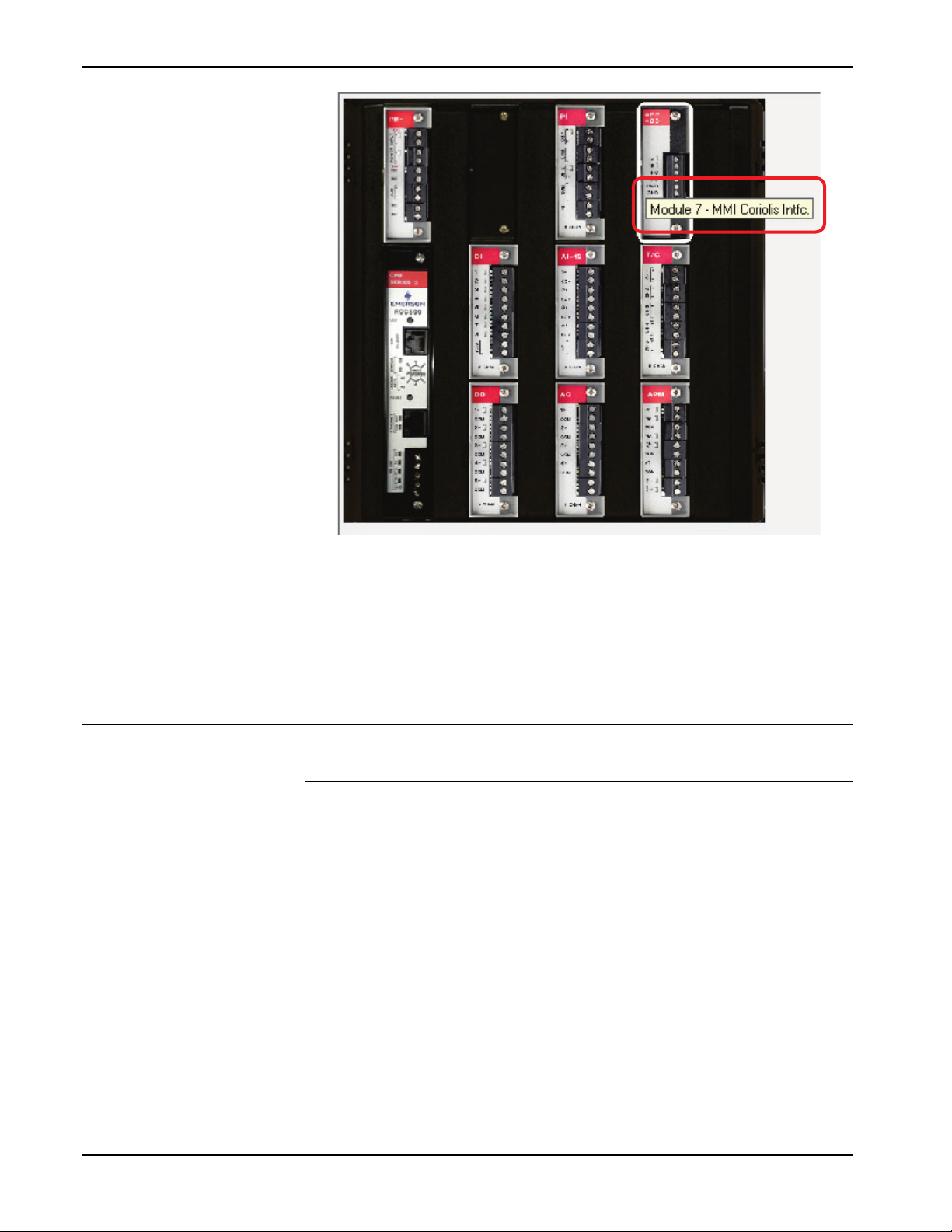
Note: Once the module is installed, you can identify a ROC800
Coriolis Interface module from the label on the face of the
module. On the FB107, the label is on the side of the physical
case. Using ROCLINK 800, click the APP 485 module shown in
the ROCLINK 800 graphic display. A label appears identifying
the module (see Figures 3 and 4).
Figure 4. Micro Motion Coriolis Interface Module (FB107)
Revised May-2016 Configuration 9
Page 14
Micro Motion Coriolis Interface Module User Manual (for ROC800-Series and FloBoss 107)
For the ROC800
1. From the Directory Tree, double-click User Display.
For the FB107
1. From the Directory Tree, double-click Application Module.
Figure 5. Micro Motion Coriolis Interface Module (ROC800)
You must configure the module before you can establish
communications with the Coriolis meter. To configure the module (after
successfully installing and wiring the module) proceed through the
screens as shown in this chapter.
3.1 Coriolis Setup and Values Screen
Note: The Coriolis Setup and Values screen is identical for both the
FB107 and ROC800/ROC800L.
Use this screen to configure communications with the Coriolis meter,
perform meter calibration, view flow rates and totals, and view
diagnostic information. To access this screen:
2. Double-click Display #66 – Coriolis Setup and Values. The
Coriolis Setup and Values screen displays.
2. Double-click MMI Coriolis Intfc.
3. Double-click Display #66, Coriolis Setup and Values.
4. Double-click 1 – Meter #1. The Coriolis Setup and Values screen
displays.
10 Configuration Revised May-2016
Page 15
Micro Motion Coriolis Interface Module User Manual (for ROC800-Series and FloBoss 107)
Field
Description
Figure 6. Coriolis Setup and Values
Notes:
The Coriolis Setup and Values screen has a tab format. Sections
3.1.1 through 3.1.11 discuss the requirements for each tab on the
Coriolis Setup and Values screen.
Two fields (Point Number and Meter Tag) at the top of the
screen appear on all tabs (see Figure 5).
For many fields on these screens, bracketed numbers follow the
field labels (see Figure 5). These numbers identify the specific
Modbus register in the Coriolis meter’s core processor that
provides the value.
1. Review the values in the following fields:
Point Number
Meter Tag
Selects the Coriolis meter to configure. Click
to display a drop-down menu of all meters.
Sets a short (10-character) identifier for the
selected Coriolis meter.
Revised May-2016 Configuration 11
Page 16

Micro Motion Coriolis Interface Module User Manual (for ROC800-Series and FloBoss 107)
Note: The default value for the Point Number field is x – Meter#x,
corresponding to the number of meters your device supports
(1 – Meter#1, 2 – Meter#2, and so on). Similarly, Meter
Tag is the default value for the Meter Tag field until you
provide a value. The values displayed in the examples in this
documentation are for illustrative purposes only and do not
reflect the factory default.
2. Click Apply to save any changes you have made to this screen.
3. Proceed to Section 3.1.1 to configure the General tab.
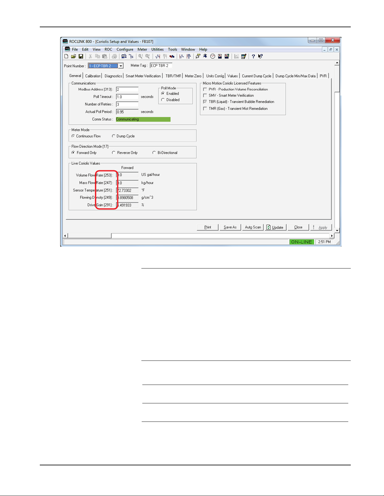
3.1.1 Coriolis Setup and Values – General Tab
Use this tab (which displays when you access the Coriolis Setup and
Values screen) to configure communications with one or more Coriolis
meters, configure and enable polling, and set communications
parameters.
Figure 7. Coriolis Setup and Values – General Tab
12 Configuration Revised May-2016
Page 17

Micro Motion Coriolis Interface Module User Manual (for ROC800-Series and FloBoss 107)
Field
Description
1. Review the values in the following fields:
Communications
Modbus Address
Poll Timeout
Number of Retries
Actual Poll Period
Enter the Modbus address of the target Coriolis
device. Valid values are 1–15, 32–47, 64–79,
and 96–110. The default is 255.
Note: The Modbus address you select must be
unique and not assigned to any other
meter connected to this module. That is,
you cannot select Address 2 for meter 2
if that address is already assigned to
meter 1.
Sets the amount of time, in seconds, the
program waits to receive a response from a
Coriolis meter. If a response is not received
within the specified time period, the message is
retried or the meter is marked with a response
timeout status in the Comm Status field.
Sets the number of times the program attempts
to successfully communicate with the selected
Coriolis meter before issuing a response
timeout status in the Comm Status field. If a
meter does not respond within the specified
number of retries, the program attempts to
restore communications with the meter every
10 seconds.
This read-only field shows the period of time,
in seconds, between meter polls.
Comm Status
This read-only field shows the current
communication status with the selected meter.
Valid values are Communication Disabled,
Communicating, Configuring Slot Registers,
Retrying, Response Timeout, Invalid CRC,
Invalid Response Format, and Slot Register
Configuration Failed, Slow Poll Mode, Reset
Totals Failed, and Incompatible Target Device.
Note: “Slow poll mode” occurs when the
module’s poll request fails, all retries are
exhausted, and the device is not
responding (which might occur if the
connecting wire has been cut). In this
case, the device automatically slows
polling, shifting from a once-per-second
poll sequence to a once-every-10seconds poll sequence. Once the
communication problem is resolved,
normal polling resumes within 10
seconds.
Revised May-2016 Configuration 13
Page 18

Micro Motion Coriolis Interface Module User Manual (for ROC800-Series and FloBoss 107)
Field
Description
using the Continuous Flow meter mode.
Poll Mode
Meter Mode
Flow Direction Mode
Enables polling between the module and the
selected Coriolis meter. Valid values are
Enabled and Disabled. The default is
Disabled.
Note: When you select Enabled, the module
re-synchronizes with the current value
of the Coriolis device’s mass and
volume accumulators. If any flow occurs
during Disabled, it will not be recorded
by the module accumulations. To avoid
accumulation issues, you must assure
the Coriolis device is in a state of noflow when disabling polling.
Defines how the module handles flow. Valid
values are Continuous Flow and Dump
Cycle. The default is Continuous Flow.
For liquid flow measurement, use Dump Cycle
mode. For gas flow measurement, use
Continuous mode.
Sets the Flow Direction configured for the
meter. The default is Forward Only.
Note: Bi-Directional is available only when
Live Coriolis Values
Volume Flow Rate
Mass Flow Rate
Sensor Temperature
This read-only field shows the current volume
flow rate, as reported by the meter. Configure
display units using the Units Configuration tab.
The Flow Direction Mode you select controls
the values shown in this frame. Values in the
Forward column display only if you select
Forward Only or Bi-Directional. Values in the
Reverse column display only if you select
Reverse Only or Bi-Directional.
This read-only field shows the current mass
flow rate, as reported by the meter. Configure
display units using the Units Configuration tab.
The Flow Direction Mode you select controls
the values shown in this frame. Values in the
Forward column display only if you select
Forward Only or Bi-Directional. Values in the
Reverse column display only if you select
Reverse Only or Bi-Directional.
This read-only field shows the current
temperature value retrieved from the meter.
You configure the display units using the Units
Configuration tab.
14 Configuration Revised May-2016
Flowing Density
This read-only field shows the current density
value retrieved from the meter. Configure
display units using the Units Configuration tab.
Page 19
Micro Motion Coriolis Interface Module User Manual (for ROC800-Series and FloBoss 107)
Field
Description
Drive Gain
Micro Motion
Coriolis Licensed
Features
This read-only field shows, as a percentage,
the current drive gain value.
This read-only field shows the specific
licensed features of the Coriolis meter which
are currently active.
2. Click Apply to save any changes you have made to this screen.
3. Proceed to Section 3.1.2 to configure the Calibration tab.
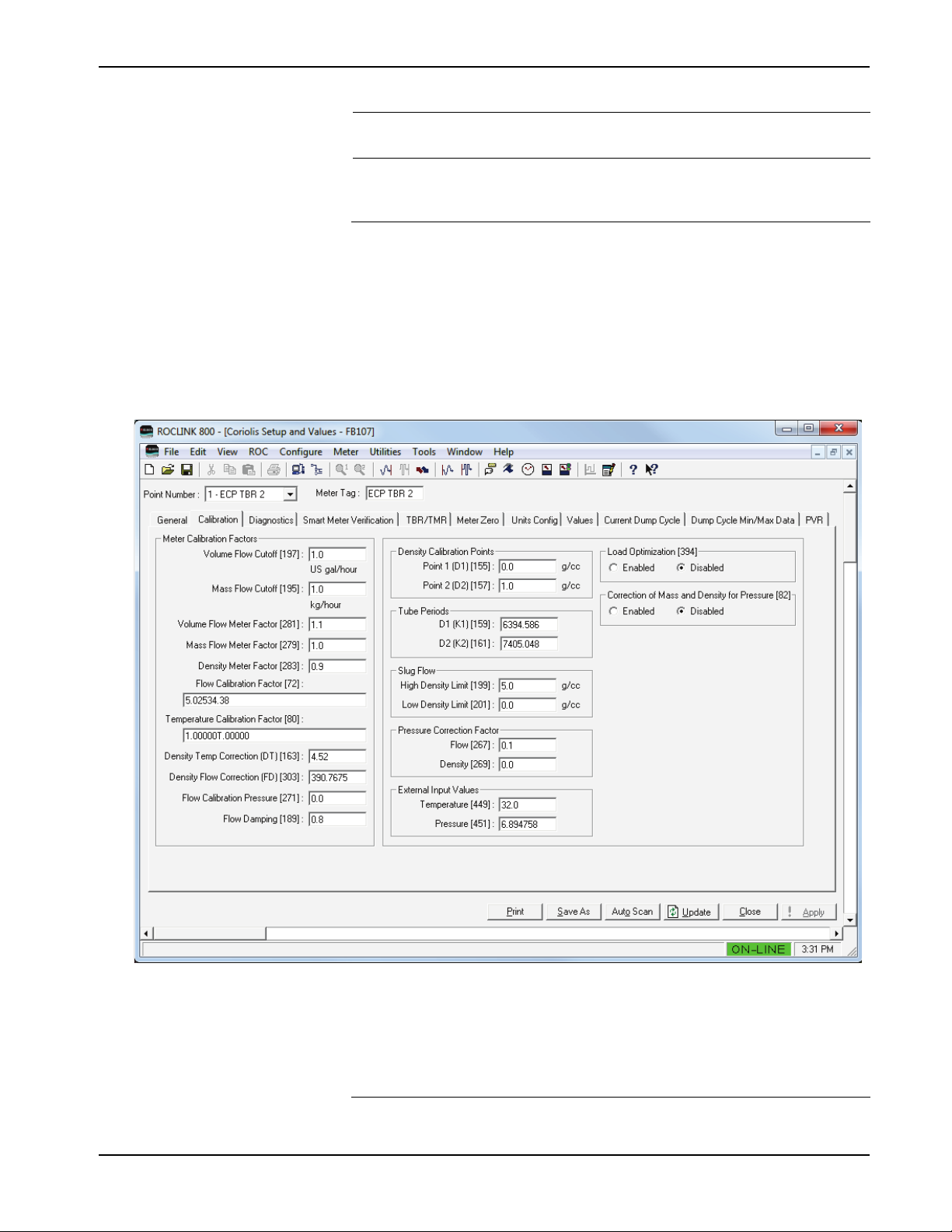
3.1.2 Coriolis Setup and Values – Calibration Tab
Use this screen to perform and view meter calibration factors. To access
this screen:
1. Select the Calibration tab. The Calibration screen displays:
Figure 8. Coriolis Setup and Values – Calibration Tab
2. Review—and change as necessary—the values in the following
fields:
Field Description
Revised May-2016 Configuration 15
Page 20

Micro Motion Coriolis Interface Module User Manual (for ROC800-Series and FloBoss 107)
Field Description
Volume Flow Cutoff
Mass Flow Cutoff
Volume Flow Meter
Factor
Mass Flow Meter
Factor
Density Meter Factor
Flow Calibration
Factor
Temperature
Calibration Factor
Density Temp
Correction (DT)
Sets the Volume Flow Cutoff value for the
target Coriolis meter. The default is 0.
Sets the Mass Flow Cutoff value for the target
Coriolis meter. The default is 0.
Sets the Volume Flow Meter Factor value for
the target Coriolis meter. Valid values are from
0.8 to 1.2. The default is 0.
Sets the Mass Flow Meter value for the target
Coriolis meter. Valid values are from 0.8 to 1.2.
The default is 0.
Sets the Density Meter Factor value for the
selected Coriolis meter. Enter any decimal
value greater than zero. The system multiplies
this value by the live density reading to
produce the published density value.
Sets the Flow Calibration Factor value for the
selected Coriolis meter. The default is 0.
Sets the Temperature Calibration Factor value
for the selected Coriolis meter. The default is 0.
Sets the Density Temperature Correction value
for the selected Coriolis meter. Valid values are
from -20 to 20. The default is 0.0.
Density Flow
Correction (FD)
Flow Calibration
Pressure
Flow Damping
Density Calibration
Points
Tube Periods
Slug Flow
Sets the Density Flow Correction value for the
selected Coriolis meter. The default is 0.0.
Sets the Flow Calibration Pressure value of the
selected Coriolis meter. Enter any decimal
value greater than zero. The default is 0.0.
Sets the flow rate internal damping in seconds.
Valid values are from 0 to 60 seconds. The
default is 0.0.
Sets the values for Density Calibration Point 1
(D1) and Density Calibration Point 2 (D2). Valid
values are from 0 to 5 g/cc. The default is 0.0.
Sets the values for Tube Period D1 (K1) and
Tube Period D2 (K2) from the physical Coriolis
sensor plates. K1 is the tube period when the
sensor is filled with a fluid of Density D1. K2 is
the tube period when the sensor is filled with a
fluid of Density D1. Both of these values are in
units of microseconds. Valid values are from
1000 to 50000. The default is 0.0.
Sets, in g/cc, the high and low density values
for slug flow. The high density limit should be
greater than the low value. Valid values are
from 0 to 5 g/cc. The default is 0.0.
16 Configuration Revised May-2016
Page 21

Micro Motion Coriolis Interface Module User Manual (for ROC800-Series and FloBoss 107)
Field Description
Pressure Correction
Factor
External Input Values
Load Optimization
Correction of Mass
and Density for
Pressure
Sets the values for Pressure Correction Factor
for flow and density. Valid values are from -0.1
to 0.1. The default is 0.0.
Sets the values for External Input Values for
temperature and pressure. Valid temperature
values range from –240 °C to 450 °C. Valid
pressure values range from –.5 to 10000 BAR.
The default for both is 0.0.
Enables Load Optimization. Valid values are
Enabled and Disabled. Default is Disabled.
Enables the module to calculate compensation
for the effect of high pressure on the
measurement accuracy of the Coriolis mass
flow and density.
This calculation requires that you first provide
flow and density values for the Pressure
Correction Factors, and you must provide a
pressure value for the External Input Value.
Valid values are Enabled and Disabled. The
default is Disabled.
3. Click Apply to save any changes you have made to this screen.
4. Proceed to Section 3.1.3 to configure the Diagnostics tab.
3.1.3 Coriolis Setup and Values – Diagnostics Tab
Use this screen to view the meter status and diagnostic messages for the
selected Coriolis meter. To access this screen:
1. Select the Diagnostics tab. The Diagnostic screen displays:
Revised May-2016 Configuration 17
Page 22

Micro Motion Coriolis Interface Module User Manual (for ROC800-Series and FloBoss 107)
Figure 9. Coriolis Setup and Values – Diagnostics Tab
2. Review the values in the following fields:
Field Description
Meter Status
Sensor Failure
Data Loss Possible
Flow Direction
Meter RTD Temp Out
of Range
Line RTD Temp Out
of Range
This read-only field shows the current status
of the selected meter based on the value in
the primary Coriolis status register. Valid
values are Yes and No.
This read-only field shows the meter’s
possibility of data loss. Valid values are Yes
and No.
This read-only field shows the meter’s flow
direction. Valid values are Forward or
Reverse.
This read-only field shows whether the
temperature for the meter’s RTD is out of
range. Valid values are Yes and No.
This read-only field shows whether the
temperature for the line’s RTD is out of range.
Valid values are Yes and No.
18 Configuration Revised May-2016
Page 23

Micro Motion Coriolis Interface Module User Manual (for ROC800-Series and FloBoss 107)
Field Description
Density Outside
Standard Range
Temp. Outside
Standard Range
RAM Diagnostic
Failure
EEPROM Checksum
Failure
Drive Overrange
Density Outside of
Limits
Communication Statistics
Number Requests
Sent to Meter
This read-only field shows whether the
meter’s reported density is outside of standard
API ranges. Valid values are Yes and No.
This read-only field shows whether the
meter’s temperature is outside of standard
API ranges. Valid values are Yes and No.
This read-only field shows whether the RAM
diagnostic procedure (initiated during a power
reset) has failed. Valid values are Yes and
No.
This read-only field shows whether the
EEPROM Checksum procedure (initiated
during a power reset) has failed. Valid values
are Yes and No.
This read-only field shows whether the drive
is outside of its proscribed range. Valid values
are Yes and No.
This read-only field shows whether the
density is outside of standard limits. Valid
values are Yes and No.
This read-only field shows the total number of
Modbus requests the module has sent to the
selected meter.
Number of Good
Responses
Number of Response
Timeouts
Number of Error
Reponses
Reset Comm Stats
Meter Information
Meter Model Type
Manufacturer ID
Device Type
This read-only field shows the total number of
valid Modbus responses the module has
received from the selected meter.
This read-only field shows the total number of
instances when the program has not received
a response within the timeout period from the
selected meter.
This read-only field shows the total number of
erroneous Modbus responses the module has
received from the selected meter.
Click to reset all communication statistics
values displayed in the Communication
Statistics frame.
This read-only field shows the type of sensor
for the selected meter. Valid values are
Curved Tube and Straight Tube.
This read-only field shows the manufacturer’s
ID for the selected meter.
This read-only field shows the specific type of
meter or transmitter connected to the module.
Revised May-2016 Configuration 19
Page 24

Micro Motion Coriolis Interface Module User Manual (for ROC800-Series and FloBoss 107)
Field Description
Current Pressure
Compensation Effect
on Flow
Current Pressure
Compensation Effect
on Density
Board Temperature
Input Voltage
Live Zero
Zero Standard
Deviation
Raw Tube Frequency
Left Pickoff Voltage
This read-only field shows the current
pressure compensation effect on flow of the
Coriolis meter. Default value is 0.
This read-only field shows the current
pressure compensation effect on density of
the Coriolis meter. Default value is 0.
This read-only field shows the board
temperature of the selected meter. Default
value is 0.
This read-only field shows the input voltage
of the selected meter. Default value is 0.
This read-only field shows the live zero in
mass flow of the selected meter. Default value
is 0.
This read-only field shows the zero standard
deviation value of the selected meter. Default
value is 0.
This read-only field shows the raw tube
frequency in Hz of the selected meter. Default
value is 0.
This read-only field shows the left pickoff
voltage of the selected meter. Default value is
0.
Left Pickoff
Amplitude
Right Pickoff Voltage
Right Pickoff
Amplitude
This read-only field shows the left pickoff
amplitude in volts of the selected meter.
Default value is 0.
This read-only field shows the right pickoff
voltage of the selected meter. Default value is
0.
This read-only field shows the right pickoff
amplitude of the selected meter. Default value
is 0.
3. Proceed to Section 3.1.4 to configure the Smart Meter Verification
tab.
3.1.4 Coriolis Setup and Values – Smart Meter Verification
Use this screen to view the Smart Meter Verification status for the
selected Coriolis meter. This screen displays only if Smart Meter
Verification is available for that sensor and only if that sensor is
connected to a Coriolis meter using the 800 enhanced core processor.
Note: The message Feature not supported on this Micro Motion meter
displays if this meter does not support Smart Meter Verification.
To access this screen:
20 Configuration Revised May-2016
Page 25

Micro Motion Coriolis Interface Module User Manual (for ROC800-Series and FloBoss 107)
Sets the value the meter uses when initiating the
with Output Fixed.
1. Select the Smart Meter Verification tab. The Smart Meter
Verification screen displays:
Figure 10. Coriolis Setup and Values – Smart Meter Verification Tab
2. Review—and change as necessary—the values in the following
fields:
Field Description
Output State
Stiffness Setpoint
Start Action
Current State
Percent Complete
Sets the output state of the Smart Meter during
the verification procedure. Default is Last Value.
Sets the stiffness setpoint for the Smart Meter
verification. Valid values range from 0.0025 to
0.4.
Smart Meter verification process. Default is Start
This read-only field shows the current state of
the verification. Valid values are Stopped and
Running.
This read-only field shows the completion
percentage of the current verification procedure.
Revised May-2016 Configuration 21
Page 26

Micro Motion Coriolis Interface Module User Manual (for ROC800-Series and FloBoss 107)
Field Description
Inlet
Outlet
Abort Code
This read-only field shows the inlet stiffness
value for the verification. Valid values are 0 (In
Limits) and 1 (Out of Limits).
This read-only field shows the outlet stiffness
value for the verification. Valid values are 0 (In
Limits) and 1 (Out of Limits).
This read-only field shows the Abort (Error)
Code for the previous verification. Valid values
are:
0 = No Error
1 = User Initiated Abort
2 = Frequency Drift
3 = Unstable flow
4= No Air
5 = No Water Reference
6 = Missing Configuration Data
7 = General drive error
8 = Delta T erratic
9 = Delta T too high
10 = State running
11 = State completed
12 = Meter verification data error
13 = Unit has not been calibrated on air
14 = Unit has not been calibrated on water
15 = Meter verification configuration items are
not correct
State at Abort
Start Meter
Verification
This read-only field shows the state of the
verification when the last abort occurred. Valid
values are 16 (SMV Completed) and 0-15 (SMV
Aborted before completion).
Click to begin the verification process.
Note: The label on this button changes with the
state of the verification. Once the
verification begins, the label changes to
Abort.
3. Click Apply to save any changes you have made to this screen.
4. Proceed to Section 3.1.5 to configure the TBR/TMR tab.
3.1.5 Coriolis Setup and Values – TBR/TMR
Transient bubble remediation (TBR) applies only to liquid flow;
transient mist remediation (TMR) applies only to gas flow. This screen
displays only if the connected Micro Motion Coriolis device has the
factory-enabled TBR or TMR feature. Otherwise the message Feature
not supported on this Micro Motion meter displays. Additionally, If you
are connecting to a Micro Motion transmitter (models 1500, 1700, 2500,
2700, or 3000-series), this tab is not available.
Use this screen to configure and view the TBR and TMR settings for the
selected Coriolis meter.
22 Configuration Revised May-2016
Page 27

Micro Motion Coriolis Interface Module User Manual (for ROC800-Series and FloBoss 107)
Note: The TBR/TMR screen shown in Figure 10 is a composite,
showing both TBR and TMR values. It is only an example for
documentation purposes and would not occur in a live system.
To access this screen:
1. Select the TBR/TMR tab. The TBR/TMR screen displays.
Figure 11. Coriolis Setup and Values – TBR/TMR Tab
2. Review—and change as necessary—the values in the following
fields:
Field Description
Mode
Status
Duration of Last
Indicates whether TBR or TMR is enabled on
the selected meter.
This read-only field shows the TBR or TMR
status for the selected meter (if the option is
activated).
This read-only field shows the number of
seconds for the last recorded TBR or TMR
event.
Revised May-2016 Configuration 23
Page 28

Micro Motion Coriolis Interface Module User Manual (for ROC800-Series and FloBoss 107)
Field Description
Drive Gain
TBR (Liquid) Control
Timeout
Timeout Period
Initial Action
Drive Gain Averaging
Apply to Flow
This read-only field shows current drive gain
value, in percent, retrieved from the selected
meter.
Sets, in seconds, the amount of time the
module holds the last measured value after
first detecting a bubble.
Sets, in seconds, the amount of time the
module holds the last measured value after
first detecting a bubble. Valid values range
from 10 to 30,000 seconds. The default is 10
seconds.
Indicates whether the module holds the last
measured density value from the time period
before transient bubbles were detected. The
Set TBR Active Status Only option allows
for the indication of transient bubbles, but
takes no action. Default is Hold Last Value.
Sets the number of seconds during which the
module determines the average drive gain.
Default is 1 Second.
Determines if the TBR event affects the mass
flow rate and accumulation. Default is Yes.
Timeout Action
Timeout Alarm Type
Apply to Density
Drive Gain Threshold
Lookback Period
TMR (Gas)
Pre-Mist Ave Period
Sets the behavior of the selected meter when
the defined number of seconds in the timeout
period has passed and the TBR event is still
active. Default is Show Actual Values.
Determines the type of alarm that the module
triggers in the event of TBR timeout. Valid
values are Slug Flow or Density OOL (out of
limits). Default is Slug Flow.
Note: You must also set the Timeout Action
option to Alarm.
Determines if the TBR event modifies the
density calculations. Default is Yes
Sets the Drive Gain percentage above which
the system initiates a TBR event. The default
is 1.8.
Sets the number of seconds back in time from
which the program calculates the last
measured value (LMV) for density. Valid
values range from 5 to 30 seconds. Default is
0.
Defines, in seconds, the application goes
back in time to determine the density to use in
TMR remediation.
24 Configuration Revised May-2016
Page 29

Micro Motion Coriolis Interface Module User Manual (for ROC800-Series and FloBoss 107)
Field Description
Post-Mist Adj Delay
Drive Gain Threshold
Mass Flowrate
Unremediated
Mass Flowrate
Remediated
Mass Total
Unremediated
Mass Total
Remediated
Defines, in seconds, how long the application
waits before beginning density adjustments
due to TMR.
Sets the Drive Gain percentage that triggers a
TMR event. The default is 1.8.
This read-only field shows the mixture’s
unremediated mass flow rate.
This read-only field shows the mixture’s
remediated mass flow rate. When used with
gas meter runs on the ROC800/ROC800L or
FB107, use this value as the flow rate input.
This read-only field shows the mixture’s
unremediated accumulated mass total.
This read-only field shows the mixture’s
remediated accumulated mass total. When
used with gas meter runs on the
ROC800/ROC800L or FB107, use this value
as the accumulator input.
3. Click Apply to save any changes you have made to this screen.
4. Proceed to Section 3.1.5 to configure the Meter Zero tab.
3.1.6 Coriolis Setup and Values – Meter Zero
Note: Before you activate the zeroing process, shut off the meter’s
flow and block the meter with valves to isolate any pulsations
from the line. Refer to the appropriate Micro Motion calibration
procedures.
Zeroing the meter establishes a baseline for process measurement, by
analyzing the sensor’s output when there is no flow through the sensor
tubes.
Use this screen to perform the meter zero process for the selected
Coriolis meter. To access this screen:
1. Select the Meter Zero tab. The Meter Zero screen displays:
Revised May-2016 Configuration 25
Page 30

Micro Motion Coriolis Interface Module User Manual (for ROC800-Series and FloBoss 107)
Figure 12. Coriolis Setup and Values – Meter Zero Tab
2. Review—and change as necessary—the values in the following
fields:
Field Description
Meter Zero Status
Previous Meter Zero
Offset
New Meter Zero
Offset
Start Zero
This read-only field shows the current status
of the meter zero procedure. Valid values are
Complete; In Progress; Zeroing failed, Zero too
low; Zeroing failed, Zero too high; and Zeroing
failed, zero too noisy.
This read-only field shows the value of the
meter zero offset as determined by the
previous meter zero procedure.
This read-only field shows the value of the
meter zero offset as determined by the most
recent meter zero procedure.
Click to begin the meter zero procedure.
3. Proceed to Section 3.1.7 to configure the Units Configuration tab.
26 Configuration Revised May-2016
Page 31

Micro Motion Coriolis Interface Module User Manual (for ROC800-Series and FloBoss 107)
3.1.7 Coriolis Setup and Values – Units Configuration
Use this screen to configure the units used for the selected Coriolis
meter. To access this screen:
1. Select the Units Configuration tab. The Unit Configuration screen
displays:
Figure 13. Coriolis Setup and Values – Units Config Tab
2. Review—and change as necessary—the values in the following
fields:
Revised May-2016 Configuration 27
Page 32

Micro Motion Coriolis Interface Module User Manual (for ROC800-Series and FloBoss 107)
Field Description
Volume Flow Rate
Units
Mass Flow Rate
Units
Sets the unit of volume flow rate for the
selected meter. Click to display all defined
options.
Notes:
If you change this value, the module resets
and clears all totals. No conversion of units
occurs.
If you select Special as a flow rate unit for a
Coriolis device, the module is unable to
perform the required unit conversions for
accumulations. Instead, accumulations
display in the native internal units of the
associated core processor (liters or cubic
centimeters).
Sets the unit of mass flow rate for the selected
meter. Click to display all defined options.
Notes:
If you change this value, the module resets
and clears all totals. No conversion of units
occurs.
If you select Special as a flow rate unit for a
Coriolis device, the module is unable to
perform the required unit conversions for
accumulations. Instead, accumulations
display in the native internal units of the
associated core processor (kilograms or
grams).
Temperature Units
Density Units
Pressure Units
Mass Total Units
Volume Total Units
Sets the unit of temperature for the selected
meter. Click to display all defined options.
Sets the unit of density for the selected meter.
Click to display all defined options.
Sets the unit of pressure for the selected
meter. Click to display all defined options.
This read-only field shows the Mass Total
Units of the selected meter. The units are
determined from Mass units selected above
without a time base. Note that units differ when
measuring liquids as compared to gas. Select
units accordingly.
This read-only field shows the Volume Total
Units of the Coriolis meter. The Volume units
are determined from the selections above
without a time base.
3. Click Apply to save any changes you have made to this screen.
4. Proceed to Section 3.1.8 to configure the Values tab.
3.1.8 Coriolis Setup and Values – Values
28 Configuration Revised May-2016
Page 33
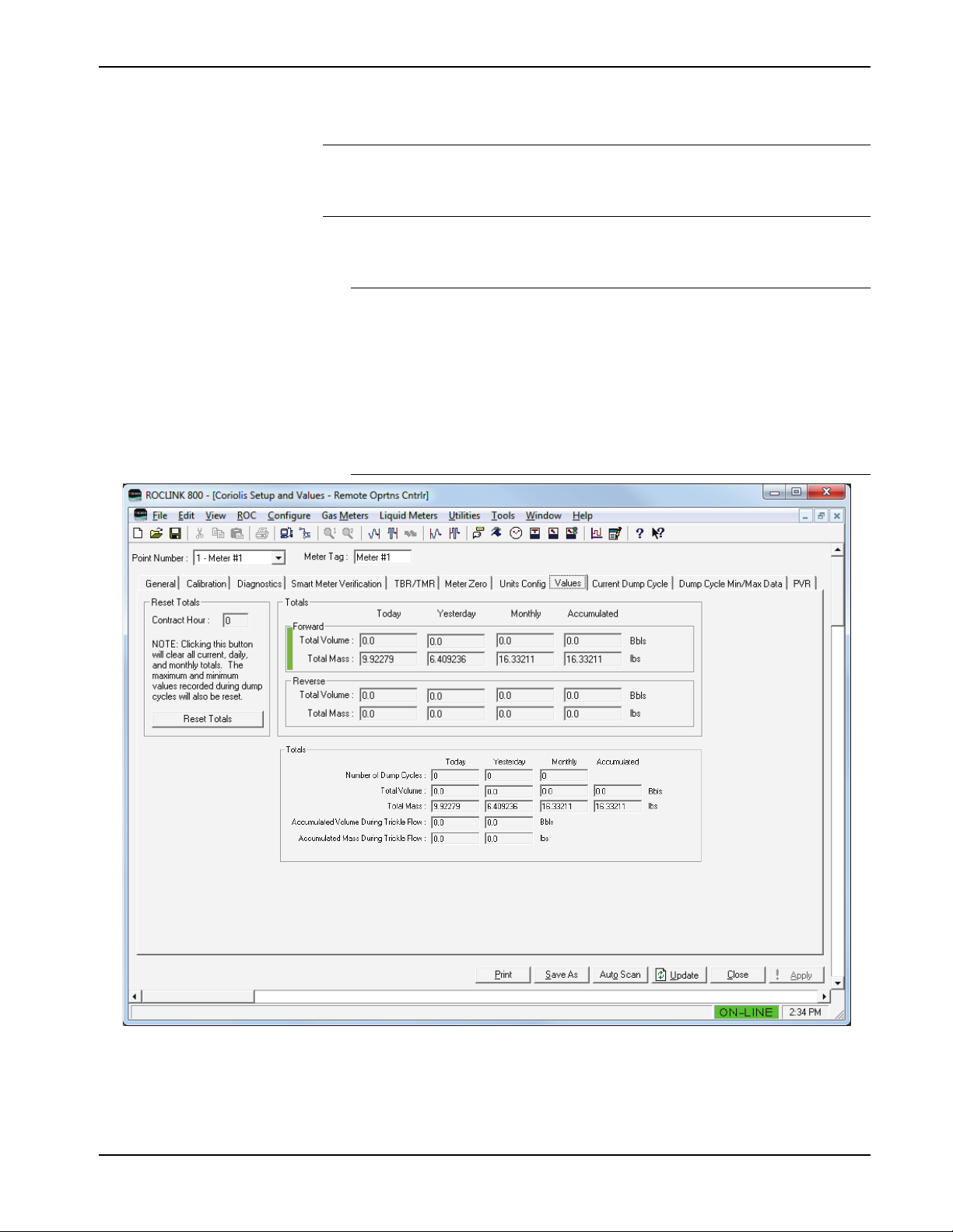
Micro Motion Coriolis Interface Module User Manual (for ROC800-Series and FloBoss 107)
Use this screen to view the total accumulated volume and mass values
for the selected Coriolis meter.
Note: The Values screen shown in Figure 13 is a composite. It is only
an example for documentation purposes and would never occur
in a live system.
To access this screen:
1. Select the Values tab. The Values screen displays.
Note:
The displayed fields on this screen depend on the values you
select for Meter Mode and Flow Direction Mode in the General
Tab.
The totals shown on the Values tab are based on the specified
contract hour. These totals are independent from the Force End
of Day selection (ROC > Information), and are not updated
when you perform a Force End of Day.
Figure 14. Coriolis Setup and Values – Values Tab
2. Review the values in the following fields:
Revised May-2016 Configuration 29
Page 34

Micro Motion Coriolis Interface Module User Manual (for ROC800-Series and FloBoss 107)
Field Description
Reset Totals
Contract Hour
Reset Totals
Totals (Forward Only, Reverse Only, Bi-Directional)
Forward Total
Volume
This read-only field shows the contract hour
as configured on the ROC > Information
screen.
Click to clear all totals and reset all minimum
and maximum values stored in the module.
These read-only fields show the volumes
accumulated in the current contract day
(Today), in the previous contract day
(Yesterday), and in the current month
(Monthly). The value in the Accumulated field
provides a running total for all dump cycles, is
updated after the completion of a dump cycle
and during trickle flow, and rolls over at
1,000,000 units. Configure units using the
Units Configuration tab.
Once the contract day is over, the value in the
Today field resets to zero, and the last value
recorded by the meter becomes the value of
the Yesterday Total Volume field.
Note: These fields display only if you select
Continuous as the Meter Mode and
either Forward Only or Bi-Directional
as the Flow Direction Mode on the
General tab.
Forward Total Mass
These read-only fields show the mass
accumulated in the current contract day
(Today), in the previous contract day
(Yesterday), and in the current month
(Monthly). The value in the Accumulated field
provides a running total for all dump cycles, is
updated after the completion of a dump cycle
and during trickle flow, and rolls over at
1,000,000 units Configure units using the Units
Configuration tab.
Once the contract day is over, the value in the
Today field resets to zero, and the last value
recorded by the meter becomes the value of
the Yesterday Total Volume field.
Note: These fields display only if you select
Dump Cycle as the Meter Mode and
either Forward Only or BiDirectional as the Flow Direction
Mode on the General tab.
30 Configuration Revised May-2016
Page 35

Micro Motion Coriolis Interface Module User Manual (for ROC800-Series and FloBoss 107)
Field Description
Reverse Total
Volume
Reverse Total Mass
These read-only fields show the volumes
accumulated in the current contract day
(Today), in the previous contract day
(Yesterday), and in the current month
(Monthly). The value in the Accumulated field
provides a running total for all dump cycles, is
updated after the completion of a dump cycle
and during trickle flow, and rolls over at
1,000,000 units. Configure units using the
Units Configuration tab.
Once the contract day is over, the value in the
Today field resets to zero, and the last value
recorded by the meter becomes the value of
the Yesterday Total Volume field.
Note: These fields display only if you select
Continuous as the Meter Mode and
either Reverse Only or Bi-Directional
as the Flow Direction Mode on the
General tab.
These read-only fields show the mass
accumulated in the current contract day
(Today), in the previous contract day
(Yesterday), and in the current month
(Monthly). The value in the Accumulated field
provides a running total for all dump cycles, is
updated after the completion of a dump cycle
and during trickle flow, and rolls over at
1,000,000 units. Configure units using the
Units Configuration tab.
Once the contract day is over, the value in the
Today field resets to zero, and the last value
recorded by the meter becomes the value of
the Yesterday Total Volume field.
Note: These fields display only if you select
Dump Cycle as the Meter Mode and
either Reverse Only or Bi-Directional
as the Flow Direction Mode on the
General tab.
Totals (Dump Cycle selected as Meter Mode on General tab)
Number of Dump
Cycles
These read-only fields show the number of
dump cycles that have occurred in the current
contract day (Today), in the previous contract
day (Yesterday), and for the current month
(Monthly).
Note: These fields display only if you select
Dump Cycle as the Meter Mode on the
General tab.
Revised May-2016 Configuration 31
Page 36

Micro Motion Coriolis Interface Module User Manual (for ROC800-Series and FloBoss 107)
These read-only fields show the volumes
General tab.
These read-only fields show the mass
General tab.
Field Description
Total Volume
Total Mass
accumulated in the current contract day
(Today), in the previous contract day
(Yesterday), and in the current month
(Monthly). The value in the Accumulated field
provides a running total for all dump cycles, is
updated after the completion of a dump cycle
and during trickle flow, and rolls over at
1,000,000 units. Configure units using the
Units Configuration tab.
Once the contract day is over, the value in the
Today field resets to zero, and the last value
recorded by the meter becomes the value of
the Yesterday Total Volume field.
Note: These fields display only if you select
Dump Cycle as the Meter Mode on the
32 Configuration Revised May-2016
Accumulated Volume
During Trickle Flow
These read-only fields show the volume
accumulated while the meter was not in a
dump cycle for the current (Today) contract
day and for the previous contract day
(Yesterday). The program updates these
values whenever a dump cycle is not in
progress. Rollover occurs at 1,000,000.
Configure units using the Units Configuration
tab.
Note: These fields display only if you select
Dump Cycle as the Meter Mode on the
General tab.
Page 37

Micro Motion Coriolis Interface Module User Manual (for ROC800-Series and FloBoss 107)
Field Description
Accumulated Mass
During Trickle Flow
These read-only fields show the mas
accumulated while the meter was not in a
dump cycle for the current (Today) contract
day and for the previous contract day
(Yesterday). The program updates these
values whenever a dump cycle is not in
progress. Rollover occurs at 1,000,000.
Configure units using the Units Configuration
tab.
Note: These fields display only if you select
Dump Cycle as the Meter Mode on the
General tab.
3. Proceed to Section 3.1.9 to configure the Current Dump Cycle tab.
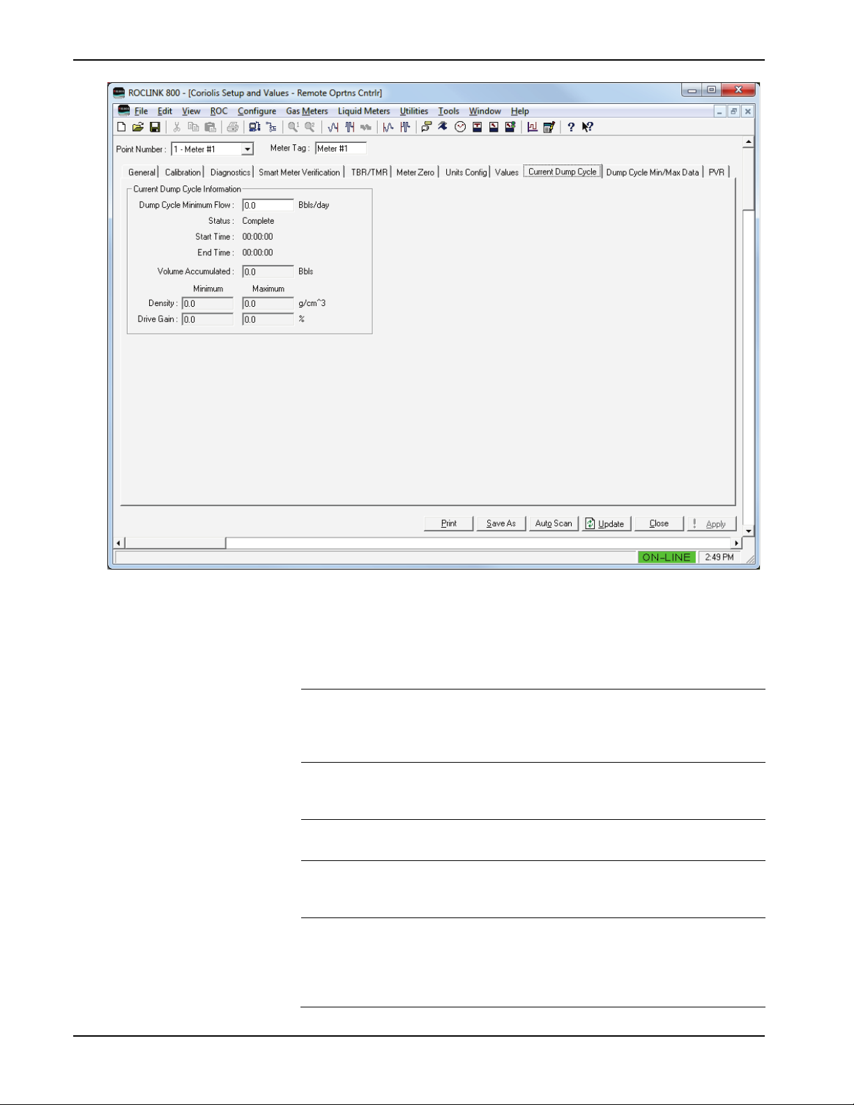
3.1.9 Coriolis Setup and Values – Current Dump Cycle
Note: This screen is available only if you select Dump Cycle as the
Meter Mode on the General tab. Dump Cycle mode applies only
to liquid flow.
Use this screen to view the current dump cycle information for the
selected Coriolis meter. To access this screen:
1. Select the Current Dump Cycle tab. The Current Dump Cycle
screen displays:
Revised May-2016 Configuration 33
Page 38
Micro Motion Coriolis Interface Module User Manual (for ROC800-Series and FloBoss 107)
Figure 15. Coriolis Setup and Values – Current Dump Cycle Tab
2. Review—and change as necessary—the values in the following
fields:
Field Description
Dump Cycle
Minimum Flow
Status
Start Time
End Time
Volume Accumulated
Sets the minimum flow rate for a dump cycle. If
flow is less than this value, the module
assumes the dump cycle is closed and trickle
flow accumulation is in effect.
This read-only field shows the current status
of a dump cycle. Valid values are Complete
and In Progress.
This read-only field shows the start time of the
current (in progress) dump cycle.
This read-only field shows the end time of
either the current (in progress) or the most
recently completed dump cycle.
This read-only field shows the volume
accumulated during either the current (in
progress) or the most recently completed dump
cycle. Configure units using the Units
Configuration tab.
34 Configuration Revised May-2016
Page 39

Micro Motion Coriolis Interface Module User Manual (for ROC800-Series and FloBoss 107)
Field Description
Density
Drive Gain
These read-only fields show the minimum and
maximum density during either the current (in
progress) or the most recently completed dump
cycle. Configure units using the Units
Configuration tab.
These read-only fields show, in percent, the
minimum and maximum drive gain during
either the current (in progress) or the most
recently completed dump cycle.
3. Click Apply to save any changes you have made to this screen.
4. Proceed to Section 3.1.10 to configure the Dump Cycle Min/Max
Data tab.
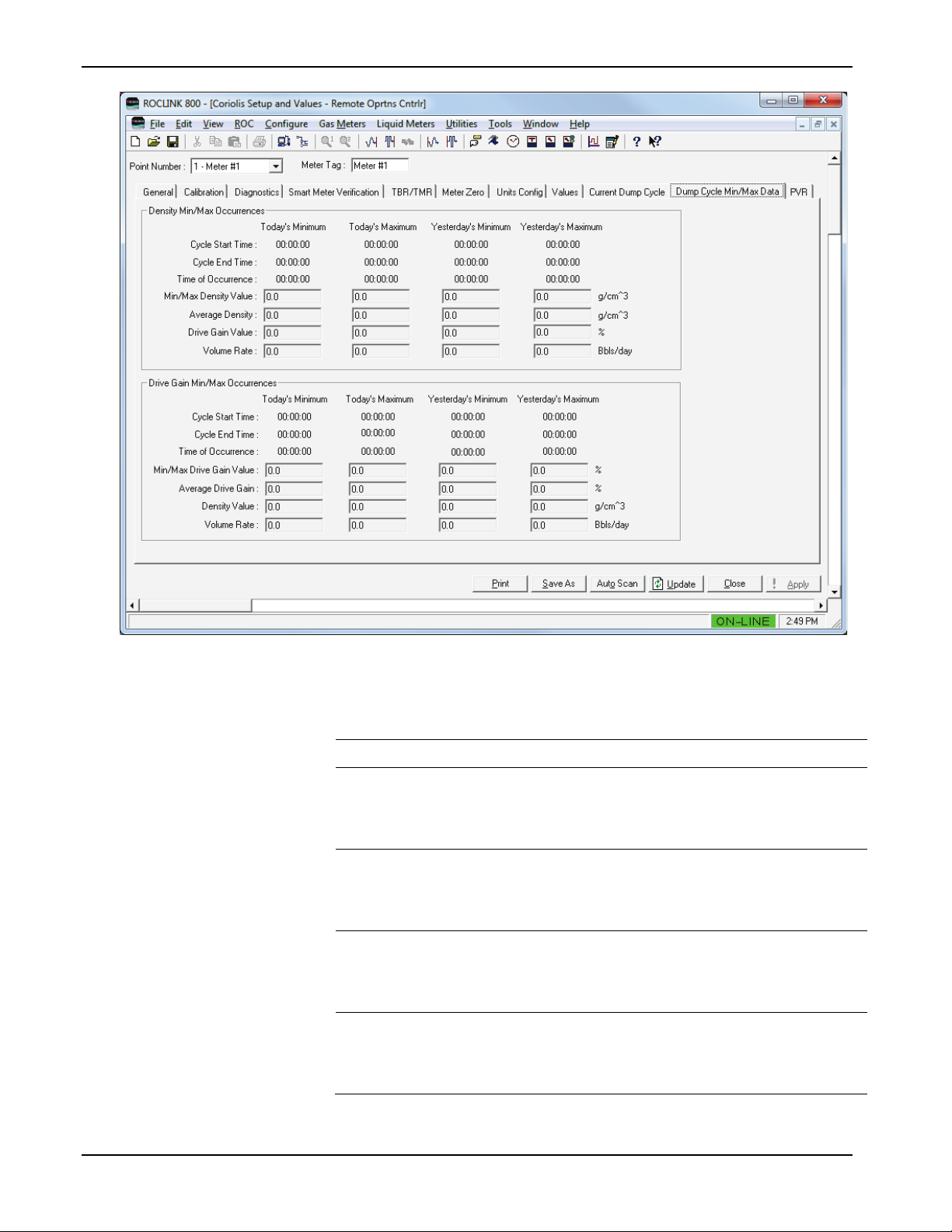
3.1.10 Coriolis Setup and Values – Dump Cycle Min/Max Data
Note: This screen is available only if you select Dump Cycle as the
Meter Mode on the General tab.
Use this screen to view density and drive gain minimum and maximum
values, cycle start and end times, and volume rates for the selected
Coriolis meter. To access this screen:
1. Select the Dump Cycle Min/Max Data tab. The Dump Cycle
Min/Max Data screen displays:
Revised May-2016 Configuration 35
Page 40
Micro Motion Coriolis Interface Module User Manual (for ROC800-Series and FloBoss 107)
Field
Description
Figure 16. Coriolis Setup and Values – Dump Cycle Min/Max Data Tab
2. Review the values in the following fields:
Density Min/Max Occurrences
Cycle Start Time
Cycle End Time
Time of Occurrence
Min/Max Density
Value
These read-only fields show the start time of the
dump cycle in which the minimum and the
maximum density values were recorded during
the current and the previous contract day.
These read-only fields show the end time of the
dump cycle in which the minimum and the
maximum density values were recorded during
the current and the previous contract day.
These read-only fields show the time at which
the minimum and the maximum density values
were recorded during the current and the
previous contract day.
These read-only fields show the minimum and
the maximum density values recorded during the
current and the previous contract day. Units are
configured in the Units Configuration tab
36 Configuration Revised May-2016
Page 41

Micro Motion Coriolis Interface Module User Manual (for ROC800-Series and FloBoss 107)
Field
Description
Average Density
Drive Gain Value
Volume Rate
Drive Gain Min/Max Occurrences
Cycle Start Time
Cycle End Time
These read-only fields show the average density
for the day at the moment when the minimum
and the maximum density values were recorded
during the current and the previous contract day.
Units are configured in the Units Configuration
tab.
These read-only fields show, in percent, the
drive gain value at the moment when the
minimum and the maximum density values were
recorded during the current and the previous
contract day.
These read-only fields show the volume rate at
the moment when the minimum and the
maximum density values were recorded during
the current and the previous contract day. Units
are configured in the Units Configuration tab.
These read-only fields show the start time of the
dump cycle in which the minimum and the
maximum drive gain values were recorded during
the current and the previous contract day.
These read-only fields show the end time of the
dump cycle in which the minimum and the
maximum drive gain values were recorded during
the current and the previous contract day.
Time of Occurrence
Min/Max Drive Gain
Value
Average Drive Gain
Density Value
Volume Rate
These read-only fields show the time at which
the minimum and the maximum drive gain values
were recorded during the current and the
previous contract day.
These read-only fields show, in percent, the
minimum and the maximum drive gain values
recorded during the current and the previous
contract day.
These read-only fields show, in percent, the
average drive gain values recorded during the
current and the previous contract day.
These read-only fields show the density value at
the moment when the minimum and the
maximum drive gain values were recorded during
the current and the previous contract day.
Configure units using the Units Configuration tab.
These read-only fields show the volume rate at
the moment when the minimum and the
maximum drive gain values occurred during the
current and the previous contract day. Configure
units using the Units Configuration tab.
3. Proceed to Section 3.1.11 to configure the PVR tab.
Revised May-2016 Configuration 37
Page 42

Micro Motion Coriolis Interface Module User Manual (for ROC800-Series and FloBoss 107)
Field
Description
3.1.11 Coriolis Setup and Values – PVR
This screen displays only if the connected Micro Motion Coriolis device
has the factory-enabled production volume reconciliation (PVR) feature.
Otherwise the message Feature not supported on this Micro Motion
meter displays.
Use this screen to configure PVR parameters and view PVR-related
flow rates and totals. To access this screen:
1. Select the PVR tab. The PVR screen displays:
38 Configuration Revised May-2016
Figure 17. Coriolis Setup and Values – PVR Tab
Note: Unit values on this screen are dynamic, and reflect the values
defined on the Units Config tab.
2. Review the values in the following fields:
PVR Configuration
Ref Temperature
Sets the temperature to which “corrected”
flowrates and totals have been corrected,
typically 60 °F or 15 °C.
Page 43

Micro Motion Coriolis Interface Module User Manual (for ROC800-Series and FloBoss 107)
Field
Description
Oil Base Density
Water Base Dens
PVR Flow Rates
Water Cut
Net Water Flw
Net Oil Flow
Mix Mass Rate
Sets the density of “dry” oil at base conditions.
The module uses this value to calculate the
water cut and determine the percentage of oil
versus water in the stream. Value is obtained
from a petroleum analysis laboratory or an
external calculation routine.
Sets the density of produced water at base
conditions. The module uses this value to
calculate the water cut and determine the
percentage of oil versus water in the stream.
Value is obtained from a petroleum analysis
laboratory or an external calculation routine.
These read-only fields show the calculated
water cut (percentage), where 100% is pure
produced water and 0% is pure oil.
These read-only fields show the volume flow
rate of the water.
These read-only fields show the mass flow rate
of the liquid mixture, unremediated by PVR.
This read-only field shows the mass flow rate of
the liquid mixture, remediated for PVR.
Mix Volume Rate
PVR Totals
Net Water Flw
Net Oil Flow
Mix Mass
This read-only field shows the volume flow rate
of the mixture, remediated by PVR.
These read-only fields show the net volume
accumulation of the water. The uncorrected
value is at line (flowing) conditions, and the
corrected value is at reference temperature
conditions.
These read-only fields show the net volume total
accumulation of the oil. The uncorrected value is
at line (flowing) conditions, and the corrected
value is at reference temperature conditions.
This read-only field shows the mass
accumulated total of the mixture, unremediated
for PVR.
3. Click Close to return to the ROCLINK 800 screen. Proceed to
Section 3.2 to save your configuration.
Revised May-2016 Configuration 39
Page 44

Micro Motion Coriolis Interface Module User Manual (for ROC800-Series and FloBoss 107)
3.2 Saving the Configuration
Whenever you modify or change the configuration, it is a good practice
to save the final configuration to memory. To save the configuration:
1. Select ROC > Flags. The Flags screen displays:
Figure 18. Flags screen
2. Click Save Configuration. A verification message displays:
Figure 19. Perform screen
3. Click Yes to begin the save process. The Status field on the Flags
screen displays In Progress. When the process completes, the
following message displays:
40 Configuration Revised May-2016
Page 45

Micro Motion Coriolis Interface Module User Manual (for ROC800-Series and FloBoss 107)
Figure 20. Save Confirmation
4. Click OK. The Status field on the Flags screen displays Completed.
5. Click Update on the Flags screen. This completes the process of
saving your new configuration.
Note: For archive purposes, you should also save this configuration to
your PC’s hard drive or a removable media (such as a flash
drive) using the File > Save Configuration option on the
ROCLINK 800 menu bar.
Revised May-2016 Configuration 41
Page 46

Micro Motion Coriolis Interface Module User Manual (for ROC800-Series and FloBoss 107)
[This page is intentionally left blank.]
42 Configuration Revised May-2016
Page 47

Micro Motion Coriolis Interface Module User Manual (for ROC800-Series and FloBoss 107)
Chapter 4 – Reference
This section provides tables of information on the point types the MMI
Coriolis Interface module uses.
Point Type 65 (for the FB107) or Point Type 244 (for the
ROC800/ROC800L)
Revised May-2016 Reference 43
Page 48

Micro Motion Coriolis Interface Module User Manual (for ROC800-Series and FloBoss 107)
Point Type 65/244: Coriolis Interface Application Module
System
Update
0
Point Tag ID
R/W
User
AC
10
0x20 → 0x7E for
Logical 0 =
Meter #6
1.00
1
Coriolis Modbus
R/W
User
UINT8
1
1 → 15,
255
1.00
instance.
2
Polling Enable
R/W
User
UINT8 1 0-1
0
1.00
3
Number of Retries
R/W
User
UINT8 1 0-255
3
1.00
Status parameter is set.
4
Poll Timeout
R/W
User
FL 4 0.5-15.0
1.0
1.00
Poll timeout
5
Actual Poll Period
R/O
System
FL 4 Any positive
number
0
1.00
4.1 Point Type 65/244: Micro Motion Coriolis Interface Module
Point type 65 (for FB107) or point type 244 (for ROC800/ROC800L) contains the parameters for configuring the Coriolis Interface Application
module. The FB107 supports four logicals of this point type, corresponding to the four meter runs the FB107 supports; the ROC800/ROC800L
supports six logicals, corresponding to the six meter runs the ROC800/ROC800L supports.
Parm
#
Address
Name Access
or User
Data
Type
Length Range Default Version
each ASCII
character
32 → 47,
64 → 79,
96 → 110
“Meter #1“,
Logical 1 =
“Meter #2”,
Logical 2 =
“Meter #3”,
Logical 3 =
“Meter #4”
For ROC800:
Logical 4 =
Meter #5
Logical 5 =
Description of functionality and
meaning of values
Point Type Description
Modbus address of the target
Coriolis meter. Note this address
cannot be changed to a value that
is in use by another logical
Enable communication with the
target Coriolis meter.
0 = Polling Disabled
1 = Polling Enabled
The number of times
communication with a Coriolis
meter will be retried before a
response timeout in the Comm
44 Revised May-2016
floating point
The time between polls to a meter
in seconds.
Page 49

Micro Motion Coriolis Interface Module User Manual (for ROC800-Series and FloBoss 107)
Point Type 65/244: Coriolis Interface Application Module
System
Update
6
Comm Status
R/O
System
UINT8 1 0-10
0
1.00
within 10 seconds.
7
Meter Status
R/O
System
UINT8 1 0-1
0
1.00
1 = Sensor Failure
Parm
#
Name Access
or User
Data
Type
Length Range Default Version
Description of functionality and
meaning of values
Current communication status with
the target meter.
0 = Communication Disabled
1 = Communicating
2 = Configuring Slot Registers
3 = Retrying
4 = Response Timeout
5 = Invalid CRC
6 = Invalid Response Format
7 = Slot Register Configuration
Failed
8 = Slow Poll Mode
9 = Reset Totals Failed
10 = Incompatible target device
firmware version
Note: “Slow poll mode” occurs
when the module’s poll request
fails, all retries are exhausted, and
the device is not responding (which
might occur if the connecting wire
has been cut). In this case, the
device automatically slows polling,
shifting from a once-per-second
poll sequence to a once-every-10seconds poll sequence. Once the
communication problem is
resolved, normal polling resumes
Revised May-2016 45
The current status of the Coriolis
meter based on the primary
Coriolis status register.
0 = No Failure
Page 50

Micro Motion Coriolis Interface Module User Manual (for ROC800-Series and FloBoss 107)
Point Type 65/244: Coriolis Interface Application Module
System
Update
8
Volume Low Flow
R/W
User
FL
4
Any floating point
0
1.00
flow.
9
Live Volume Flow
R/O
System
FL 4 Any positive
0
1.00
configuration of the meter.
Live Volume Flow
R/O
System
FL 4 Any positive
0
1.00
on the configuration of the meter.
Parm
#
Cutoff
Rate
Rate
Name Access
or User
Data
Type
Length Range Default Version
number
floating point
number
floating point
number
Description of functionality and
meaning of values
The volume flow rate limit at which
the flow rate should be considered
as no flow. This value allows the
module to identify the beginning
and end of dump cycles. Volume
accumulated below this cutoff, but
above the Coriolis meter’s low flow
cutoff is considered to be trickle
For TBR, the current volume flow
rate retrieved from the meter. Rate
units are determined based on the
For TMR, the remediated volume
flow rate retrieved from the meter.
Rate units are determined based
46 Revised May-2016
Page 51

Micro Motion Coriolis Interface Module User Manual (for ROC800-Series and FloBoss 107)
Point Type 65/244: Coriolis Interface Application Module
System
Update
10
Volume Flow Rate
R/W
System
UINT16 2 0, 15-253
0
1.00
253 = Special
11
Live Mass Flow Rate
R/O
System
FL 4 Any positive
0
1.00
the configuration of the meter.
Live Mass Flow Rate
R/O
System
FL 4 Any positive
0
1.00
meter.
Parm
#
Units
Name Access
or User
Data
Type
Length Range Default Version
Description of functionality and
meaning of values
Volume Flow Rate Units:
0 = Unknown
15 = Cubic feet/minute
16 = Gallons/minute
17 = Liters/minute
18 = Imperial gallons/minute
19 = Cubic meters/hour
22 = Gallons/second
23 = Mlllion U.S. gallons/day
24 = Liters/second
25 = Millions liters/day
26 = Cubic feet/second
27 = Cubic feet/day
28 = Cubic meters/second
29 = Cubic meters/day
30 = Imperial gallons/hour
31 = Imperial gallons/day
130 = Cubic feet/hour
131 = Cubic meters/minute
132 = Barrels/second
133 = Barrels/minute
134 = Barrels/hour
135 = Barrels/day
136 = U.S. gallons/hour
137 = Imperial gallons/second
138 = Liters/hour
Revised May-2016 47
floating point
number
floating point
number
For TBR, the current mass flow
rate retrieved from the meter. Mass
rate units are determined based on
For TMR, the unremeditated mass
flow rate retrieved from the meter.
Mass rate units are determined
based on the configuration of the
Page 52

Micro Motion Coriolis Interface Module User Manual (for ROC800-Series and FloBoss 107)
Point Type 65/244: Coriolis Interface Application Module
System
Update
12
Mass Flow Rate Units
R/W
System
UINT16 2 0, 70-253
0
1.00
253 = Special
13
Live Sensor
R/O
System
FL 4 Any positive
0
1.00
meter.
14
Temperature Units
R/W
System
UINT16 2 0, 32-35
0
1.00
35 = Kelvin
Parm
#
Name Access
or User
Data
Type
Length Range Default Version
Description of functionality and
meaning of values
Mass Flow Rate Units:
0 = Unknown
70 = Grams/second
71 = Grams/minute
72 = Grams/hour
73 = Kilograms/second
74 = Kilograms/minute
75 = Kilograms/hour
76 = Kilograms/day
77 = Metric tons/minute
78 = Metric tons/hour
79 = Metric tons/day
80 = Pounds/second
81 = Pounds/minute
82 = Pounds/hour
83 = Pounds/day
84 = Short tons (2000
pounds)/minute
85 = Short tons (2000
pounds)/hour
86 = Short tons (2000
pounds)/day
87 = Long tons (2240
pounds)/hour
88 = Long tons (2240
pounds)/day
Temperature
48 Revised May-2016
floating point
number
Current Temperature value
retrieved from the meter.
Temperature units are determined
based on the configuration of the
Temperature Units:
0 = Unknown
32 = Degrees C
33 = Degrees Fahrenheit
34 = Degrees Rankine
Page 53

Micro Motion Coriolis Interface Module User Manual (for ROC800-Series and FloBoss 107)
Point Type 65/244: Coriolis Interface Application Module
System
Update
15
Live Flowing Density
R/O
System
FL 4 Any positive
0
1.00
configuration of the meter.
16
Density Units
R/W
System
UINT16 2 0, 90-104
0
1.00
104 = Degrees API
17
Live Drive Gain
R/O
System
FL 4 Any positive
0
1.00
are percent.
18
Dump Cycle Status
R/O
System
UINT8 1 0-1
0
1.00
1 = In Progress
19
Current Dump Cycle
R/O
System
UINT32 4 0-235959
0
1.00
Byte 0 = Seconds
20
Current Dump Cycle
R/O
System
UINT32 4 0-235959
0
1.00
Byte 0 = Seconds
Parm
#
Name Access
or User
Data
Type
Length Range Default Version
floating point
number
floating point
number
Description of functionality and
meaning of values
Current Density value retrieved
from the meter. Density units are
determined based on the
Density Units:
0 = Unknown
90 = Specific gravity units
91 = Grams/cubic centimeter
92 = Kilograms/cubic meter
93 = Pounds/gallon
94 = Pounds/cubic foot
95 = Grams/milliliter
96 = Kilograms/liter
97 = Grams/liter
98 = Pounds/cubic inch
99 = Short tons (2000
pounds)/cubic yard
Current Drive Gain value retrieved
from the meter. Drive Gain units
The current status of a dump cycle.
0 = Complete
Start Time
Revised May-2016 49
End Time
The start time of the current (in
progress) or most recently
completed dump cycle.
Byte 3 = Unused
Byte 2 = Hours
Byte 1 = Minutes
The end time of the current (in
progress) or most recently
completed dump cycle.
Byte 3 = Unused
Byte 2 = Hours
Byte 1 = Minutes
Page 54

Micro Motion Coriolis Interface Module User Manual (for ROC800-Series and FloBoss 107)
Point Type 65/244: Coriolis Interface Application Module
System
Update
21
Current Dump Cycle
R/W
System
FL 4 Any positive
0
1.00
meter.
22
Current Dump Cycle
R/O
System
FL 4 Any positive
0
1.00
meter.
23
Current Dump Cycle
R/O
System
FL 4 Any positive
0
1.00
Drive Gain units are percent.
24
Current Dump Cycle
R/O
System
FL 4 Any positive
0
1.00
meter.
25
Current Dump Cycle
R/O
System
FL 4 Any positive
0
1.00
Drive Gain units are percent.
26
Today’s Total Number
R/O
System
UINT16 2 0-65536
0
1.00
contract day.
27
Today’s Total
R/W
System
FL 4 Any positive
0
1.00
configuration of the meter.
Parm
#
Name Access
Volume Accumulated
Maximum Density
Maximum Drive Gain
Minimum Density
Minimum Drive Gain
or User
Data
Type
Length Range Default Version
floating point
number
floating point
number
floating point
number
floating point
number
floating point
number
Description of functionality and
meaning of values
The volume accumulated during
the current (in progress) or most
recently completed dump cycle.
Volume Total units are determined
based on the configuration of the
The maximum density during the
current (in progress) or most
recently completed dump cycle.
Density units are determined
based on the configuration of the
The maximum drive gain during
the current (in progress) or most
recently completed dump cycle.
The minimum density during the
current (in progress) or most
recently completed dump cycle.
Density units are determined
based on the configuration of the
The minimum drive gain during the
current (in progress) or most
recently completed dump cycle.
of Dump Cycles
Accumulated Volume
50 Revised May-2016
floating point
number
The number of dump cycles that
have occurred in the current
The volume accumulated in the
current contract day. Volume Total
units are determined based on the
Page 55

Micro Motion Coriolis Interface Module User Manual (for ROC800-Series and FloBoss 107)
Point Type 65/244: Coriolis Interface Application Module
System
Update
28
Volume Total Units
R/O
System
UINT16 2 0, 40-253
0
1.00
253 = Special
29
Today’s Total
R/W
System
FL 4 Any positive
0
1.00
configuration of the meter.
30
Mass Total Units
R/O
System
UINT16 2 0, 60-253
0
1.00
253 = Special
31
Yesterday’s Total
R/O
System
UINT16 2 0-65536
0
1.00
contract day.
32
Yesterday’s Total
R/W
System
FL 4 Any positive
0
1.00
configuration of the meter.
33
Yesterday’s Total
R/W
System
FL 4 Any positive
0
1.00
configuration of the meter.
34
Monthly Total Number
R/O
System
UINT32
4
0-4294967295
0
1.00
current month
35
Monthly Total
R/W
System
FL 4 Any positive
0
1.00
configuration of the meter.
Parm
#
Name Access
Accumulated Mass
Number of Dump
Cycles
Accumulated Volume
or User
Data
Type
Length Range Default Version
floating point
number
floating point
number
Description of functionality and
meaning of values
Volume Total Units:
0 = Unknown
40 = U.S. gallons
41 = Liters
42 = Imperial gallons
43 = Cubic Meters
46 = Barrels (42 U.S. gallons)
112 = Cubic feet
The mass accumulated in the
current contract day. Mass Total
units are determined based on the
Mass Total Units:
0 = Unknown
60 = Grams
61 = Kilograms
62 = Metric tons
63 = Pounds
64 = Short tons (2000 pounds)
65 = Long tons (2240 pounds)
The number of dump cycles that
have occurred in the previous
The volume accumulated in the
previous contract day. Volume
units are determined based on the
Accumulated Mass
of Dump Cycle
Revised May-2016 51
Accumulated Volume
floating point
number
floating point
number
The mass accumulated in the
previous contract day. Mass units
are determined based on the
The total number of dump cycles
that have occurred during the
The volume accumulated in the
current month. Volume units are
determined based on the
Page 56

Micro Motion Coriolis Interface Module User Manual (for ROC800-Series and FloBoss 107)
Point Type 65/244: Coriolis Interface Application Module
System
Update
36
Monthly Total
R/W
System
FL 4 Any positive
0
1.00
configuration of the meter.
37
Today’s Maximum
R/O
System
UINT32 4 0-235959
0
1.00
Byte 0 = Seconds
38
Today’s Maximum
R/O
System
UINT32 4 0-235959
0
1.00
Byte 0 = Seconds
39
Today’s Maximum
R/O
System
UINT32 4 0-235959
0
1.00
Byte 0 = Seconds
40
Today’s Maximum
R/O
System
FL 4 Any positive
0
1.00
configuration of the meter.
41
Today’s Average
R/O
System
FL 4 Any positive
0
1.00
meter.
Parm
#
Name Access
Accumulated Mass
Density Cycle Start
Time
Density Cycle End
Time
Density Time of
Occurrence
or User
Data
Type
Length Range Default Version
floating point
number
Description of functionality and
meaning of values
The mass accumulated in the
current month. Mass units are
determined based on the
The start time of the dump cycle in
which the maximum density value
for the current contract day was
recorded.
Byte 3 = Unused
Byte 2 = Hours
Byte 1 = Minutes
The end time of the dump cycle in
which the maximum density value
for the current contract day was
recorded.
Byte 3 = Unused
Byte 2 = Hours
Byte 1 = Minutes
The time at which the maximum
density value for the current
contract day was recorded.
Byte 3 = Unused
Byte 2 = Hours
Byte 1 = Minutes
Density
Density
52 Revised May-2016
floating point
number
floating point
number
The maximum density value
recorded during the current
contract day. Density units are
determined based on the
The average density value during
active dump cycles recorded
during the current contract day.
Density units are determined
based on the configuration of the
Page 57

Micro Motion Coriolis Interface Module User Manual (for ROC800-Series and FloBoss 107)
Point Type 65/244: Coriolis Interface Application Module
System
Update
42
Drive Gain at Today’s
R/O
System
FL 4 Any positive
0
1.00
percent.
43
Volume Rate at
R/O
System
FL 4 Any positive
0
1.00
meter.
44
Today’s Minimum
R/O
System
UINT32 4 0-235959
0
1.00
Byte 0 = Seconds
45
Today’s Minimum
R/O
System
UINT32 4 0-235959
0
1.00
Byte 0 = Seconds
46
Today’s Minimum
R/O
System
UINT32 4 0-235959
0
1.00
Byte 0 = Seconds
47
Today’s Minimum
R/O
System
FL 4 Any positive
0
1.00
configuration of the meter.
Parm
#
Name Access
Maximum Density
Today’s Maximum
Density
Density Cycle Start
Time
Density Cycle End
Time
or User
Data
Type
Length Range Default Version
floating point
number
floating point
number
Description of functionality and
meaning of values
The drive gain value recorded
when the maximum density value
for the current contract day
occurred. Drive gain units are
The volume rate recorded when
the maximum density value for the
current contract day occurred.
Volume units are determined
based on the configuration of the
The start time of the dump cycle in
which the minimum density value
for the current contract day was
recorded.
Byte 3 = Unused
Byte 2 = Hours
Byte 1 = Minutes
The end time of the dump cycle in
which the minimum density value
for the current contract day was
recorded.
Byte 3 = Unused
Byte 2 = Hours
Byte 1 = Minutes
Density Time of
Occurrence
Density
Revised May-2016 53
floating point
number
The time at which the minimum
density value for the current
contract day was recorded.
Byte 3 = Unused
Byte 2 = Hours
Byte 1 = Minutes
The minimum density value
recorded during the current
contract day. Density units are
determined based on the
Page 58

Micro Motion Coriolis Interface Module User Manual (for ROC800-Series and FloBoss 107)
Point Type 65/244: Coriolis Interface Application Module
System
Update
48
Drive Gain at Today’s
R/O
System
FL 4 Any positive
0
1.00
percent.
49
Volume Rate at
R/O
System
FL 4 Any positive
0
1.00
meter.
50
Yesterday’s Maximum
R/O
System
UINT32 4 0-235959
0
1.00
Byte 0 = Seconds
51
Yesterday’s Maximum
R/O
System
UINT32 4 0-235959
0
1.00
Byte 0 = Seconds
52
Yesterday’s Maximum
R/O
System
UINT32 4 0-235959
0
1.00
Byte 0 = Seconds
53
Yesterday’s Maximum
R/O
System
FL 4 Any positive
0
1.00
configuration of the meter.
Parm
#
Name Access
Minimum Density
Today’s Minimum
Density
Density Cycle Start
Time
Density Cycle End
Time
or User
Data
Type
Length Range Default Version
floating point
number
floating point
number
Description of functionality and
meaning of values
The drive gain value recorded
when the minimum density value
for the current contract day
occurred. Drive gain units are
The volume rate recorded when
the minimum density value for the
current contract day occurred.
Volume units are determined
based on the configuration of the
The start time of the dump cycle in
which the maximum density value
for the previous contract day was
recorded.
Byte 3 = Unused
Byte 2 = Hours
Byte 1 = Minutes
The end time of the dump cycle in
which the maximum density value
for the previous contract day was
recorded.
Byte 3 = Unused
Byte 2 = Hours
Byte 1 = Minutes
Density Time of
Occurrence
Density
54 Revised May-2016
floating point
number
The time at which the maximum
density value for the previous
contract day was recorded.
Byte 3 = Unused
Byte 2 = Hours
Byte 1 = Minutes
The maximum density value
recorded during the previous
contract day. Density units are
determined based on the
Page 59

Micro Motion Coriolis Interface Module User Manual (for ROC800-Series and FloBoss 107)
Point Type 65/244: Coriolis Interface Application Module
System
Update
54
Yesterday’s Average
R/O
System
FL 4 Any positive
0
1.00
meter.
55
Drive Gain at
R/O
System
FL 4 Any positive
0
1.00
percent.
56
Volume Rate at
R/O
System
FL 4 Any positive
0
1.00
meter.
57
Yesterday’s Minimum
R/O
System
UINT32 4 0-235959
0
1.00
Byte 0 = Seconds
58
Yesterday’s Minimum
R/O
System
UINT32 4 0-235959
0
1.00
Byte 0 = Seconds
59
Yesterday’s Minimum
R/O
System
UINT32 4 0-235959
0
1.00
Byte 0 = Seconds
Parm
#
Name Access
Density
Yesterday’s Maximum
Density
Yesterday’s Maximum
Density
Density Cycle Start
Time
or User
Data
Type
Length Range Default Version
floating point
number
floating point
number
floating point
number
Description of functionality and
meaning of values
The average density value during
active dump cycles recorded
during the previous contract day.
Density units are determined
based on the configuration of the
The drive gain value recorded
when the maximum density value
for the previous contract day
occurred. Drive gain units are
The volume rate recorded when
the maximum density value for the
previous contract day occurred.
Volume units are determined
based on the configuration of the
The start time of the dump cycle in
which the minimum density value
for the previous contract day was
recorded.
Byte 3 = Unused
Byte 2 = Hours
Byte 1 = Minutes
Density Cycle End
Time
Density Time of
Occurrence
Revised May-2016 55
The end time of the dump cycle in
which the minimum density value
for the previous contract day was
recorded.
Byte 3 = Unused
Byte 2 = Hours
Byte 1 = Minutes
The time at which the minimum
density value for the previous
contract day was recorded.
Byte 3 = Unused
Byte 2 = Hours
Byte 1 = Minutes
Page 60

Micro Motion Coriolis Interface Module User Manual (for ROC800-Series and FloBoss 107)
Point Type 65/244: Coriolis Interface Application Module
System
Update
60
Yesterday’s Minimum
R/O
System
FL 4 Any positive
0
1.00
configuration of the meter.
61
Drive Gain at
R/O
System
FL 4 Any positive
0
1.00
percent.
62
Volume Rate at
R/O
System
FL 4 Any positive
0
1.00
meter.
63
Today’s Maximum
R/O
System
UINT32 4 0-235959
0
1.00
Byte 0 = Seconds
64
Today’s Maximum
R/O
System
UINT32 4 0-235959
0
1.00
Byte 0 = Seconds
65
Today’s Maximum
R/O
System
UINT32 4 0-235959
0
1.00
Byte 0 = Seconds
Parm
#
Name Access
Density
Yesterday’s Minimum
Density
Yesterday’s Minimum
Density
Drive Gain Cycle Start
Time
or User
Data
Type
Length Range Default Version
floating point
number
floating point
number
floating point
number
Description of functionality and
meaning of values
The minimum density value
recorded during the previous
contract day. Density units are
determined based on the
The drive gain value recorded
when the minimum density value
for the previous contract day
occurred. Drive gain units are
The volume rate recorded when
the minimum density value for the
previous contract day occurred.
Volume units are determined
based on the configuration of the
The start time of the dump cycle in
which the maximum drive gain
value for the current contract day
was recorded.
Byte 3 = Unused
Byte 2 = Hours
Byte 1 = Minutes
Drive Gain Cycle End
Time
Drive Gain Time of
Occurrence
56 Revised May-2016
The end time of the dump cycle in
which the maximum drive gain
value for the current contract day
was recorded.
Byte 3 = Unused
Byte 2 = Hours
Byte 1 = Minutes
The time at which the maximum
drive gain value for the current
contract day was recorded.
Byte 3 = Unused
Byte 2 = Hours
Byte 1 = Minutes
Page 61

Micro Motion Coriolis Interface Module User Manual (for ROC800-Series and FloBoss 107)
Point Type 65/244: Coriolis Interface Application Module
System
Update
66
Today’s Maximum
R/O
System
FL 4 Any positive
0
1.00
percent.
67
Today’s Average Drive
R/O
System
FL 4 Any positive
0
1.00
Drive gain units are percent.
68
Density at Today’s
R/O
System
FL 4 Any positive
0
1.00
meter.
69
Volume Rate at
R/O
System
FL 4 Any positive
0
1.00
meter.
70
Today’s Minimum
R/O
System
UINT32 4 0-235959
0
1.00
Byte 0 = Seconds
71
Today’s Minimum
R/O
System
UINT32 4 0-235959
0
1.00
Byte 0 = Seconds
Parm
#
Name Access
Drive Gain
Gain
Maximum Drive Gain
Today’s Maximum
Drive Gain
Drive Gain Cycle Start
Time
or User
Data
Type
Length Range Default Version
floating point
number
floating point
number
floating point
number
floating point
number
Description of functionality and
meaning of values
The maximum drive gain value
recorded during the current
contract day. Drive gain units are
The average density value during
active dump cycles recorded
during the current contract day.
The density value recorded when
the maximum drive gain value for
the current contract day occurred.
Density units are determined
based on the configuration of the
The volume rate recorded when
the maximum drive gain value for
the current contract day occurred.
Volume units are determined
based on the configuration of the
The start time of the dump cycle in
which the minimum drive gain
value for the current contract day
was recorded.
Byte 3 = Unused
Byte 2 = Hours
Byte 1 = Minutes
Drive Gain Cycle End
Time
Revised May-2016 57
The end time of the dump cycle in
which the minimum drive gain
value for the current contract day
was recorded.
Byte 3 = Unused
Byte 2 = Hours
Byte 1 = Minutes
Page 62

Micro Motion Coriolis Interface Module User Manual (for ROC800-Series and FloBoss 107)
Point Type 65/244: Coriolis Interface Application Module
System
Update
72
Today’s Minimum
R/O
System
UINT32 4 0-235959
0
1.00
Byte 0 = Seconds
73
Today’s Minimum
R/O
System
FL 4 Any positive
0
1.00
percent.
74
Density at Today’s
R/O
System
FL 4 Any positive
0
1.00
meter.
75
Volume Rate at
R/O
System
FL 4 Any positive
0
1.00
meter.
76
Yesterday’s Maximum
R/O
System
UINT32 4 0-235959
0
1.00
Byte 0 = Seconds
77
Yesterday’s Maximum
R/O
System
UINT32 4 0-235959
0
1.00
Byte 0 = Seconds
Parm
#
Name Access
Drive Gain Time of
Occurrence
Drive Gain
Minimum Drive Gain
Today’s Minimum
Drive Gain
Drive Gain Cycle Start
Time
or User
Data
Type
Length Range Default Version
floating point
number
floating point
number
floating point
number
Description of functionality and
meaning of values
The time at which the minimum
drive gain value for the current
contract day was recorded.
Byte 3 = Unused
Byte 2 = Hours
Byte 1 = Minutes
The minimum drive gain value
recorded during the current
contract day. Drive gain units are
The density value recorded when
the minimum drive gain value for
the current contract day occurred.
Density units are determined
based on the configuration of the
The volume rate recorded when
the minimum drive gain value for
the current contract day occurred.
Volume units are determined
based on the configuration of the
The start time of the dump cycle in
which the maximum drive gain
value for the previous contract day
was recorded.
Byte 3 = Unused
Byte 2 = Hours
Byte 1 = Minutes
Drive Gain Cycle End
Time
58 Revised May-2016
The end time of the dump cycle in
which the maximum drive gain
value for the previous contract day
was recorded.
Byte 3 = Unused
Byte 2 = Hours
Byte 1 = Minutes
Page 63

Micro Motion Coriolis Interface Module User Manual (for ROC800-Series and FloBoss 107)
Point Type 65/244: Coriolis Interface Application Module
System
Update
78
Yesterday’s Maximum
R/O
System
UINT32 4 0-235959
0
1.00
Byte 0 = Seconds
79
Yesterday’s Maximum
R/O
System
FL 4 Any positive
0
1.00
percent.
80
Yesterday’s Average
R/O
System
FL 4 Any positive
0
1.00
percent.
81
Density at Yesterday’s
R/O
System
FL 4 Any positive
0
1.00
meter.
82
Volume Rate at
R/O
System
FL 4 Any positive
0
1.00
meter.
83
Yesterday’s Minimum
R/O
System
UINT32 4 0-235959
0
1.00
Byte 0 = Seconds
Parm
#
Name Access
Drive Gain Time of
Occurrence
Drive Gain
Drive Gain
Maximum Drive Gain
Yesterday’s Maximum
Drive Gain
or User
Data
Type
Length Range Default Version
floating point
number
floating point
number
floating point
number
floating point
number
Description of functionality and
meaning of values
The time at which the maximum
drive gain value for the previous
contract day was recorded.
Byte 3 = Unused
Byte 2 = Hours
Byte 1 = Minutes
The maximum drive gain value
recorded during the previous
contract day. Drive gain units are
The average drive gain value
during active dump cycles
recorded during the previous
contract day. Drive gain units are
The density value recorded when
the maximum drive gain value for
the previous contract day occurred.
Density units are determined
based on the configuration of the
The volume rate recorded when
the maximum drive gain value for
the previous contract day occurred.
Volume units are determined
based on the configuration of the
Drive Gain Cycle Start
Time
Revised May-2016 59
The start time of the dump cycle in
which the minimum drive gain
value for the previous contract day
was recorded.
Byte 3 = Unused
Byte 2 = Hours
Byte 1 = Minutes
Page 64

Micro Motion Coriolis Interface Module User Manual (for ROC800-Series and FloBoss 107)
Point Type 65/244: Coriolis Interface Application Module
System
Update
84
Yesterday’s Minimum
R/O
System
UINT32 4 0-235959
0
1.00
Byte 0 = Seconds
85
Yesterday’s Minimum
R/O
System
UINT32 4 0-235959
0
1.00
Byte 0 = Seconds
86
Yesterday’s Minimum
R/O
System
FL 4 Any positive
0
1.00
percent.
87
Density at Yesterday’s
R/O
System
FL 4 Any positive
0
1.00
meter.
88
Volume Rate at
R/O
System
FL 4 Any positive
0
1.00
meter.
89
Meter Zero
R/W
User and
UINT8 1 0-1
0
1.00
1 = Start Meter Zero
Parm
#
Name Access
Drive Gain Cycle End
Time
Drive Gain Time of
Occurrence
Drive Gain
Minimum Drive Gain
or User
Data
Type
Length Range Default Version
floating point
number
floating point
number
Description of functionality and
meaning of values
The end time of the dump cycle in
which the minimum drive gain
value for the previous contract day
was recorded.
Byte 3 = Unused
Byte 2 = Hours
Byte 1 = Minutes
The time at which the minimum
drive gain value for the previous
contract day was recorded.
Byte 3 = Unused
Byte 2 = Hours
Byte 1 = Minutes
The minimum drive gain value
recorded during the previous
contract day. Drive gain units are
The density value recorded when
the minimum density value for the
previous contract day occurred.
Density units are determined
based on the configuration of the
Yesterday’s Minimum
Drive Gain
System
60 Revised May-2016
floating point
number
The volume rate recorded when
the minimum drive gain value for
the previous contract day occurred.
Volume units are determined
based on the configuration of the
Perform Meter Zero. The value of
this parameter returns to 0 once
the Start Meter process is
complete.
0 = No action
Page 65

Micro Motion Coriolis Interface Module User Manual (for ROC800-Series and FloBoss 107)
Point Type 65/244: Coriolis Interface Application Module
System
Update
90
Meter Zero Status
R/O
System
UINT8 1 0-4
0
1.00
4 = Zeroing failed, zero too noisy
91
Previous Meter Zero
R/O
System
FL
4
Any valid floating
0
1.00
Start Meter Zero cycle.
92
New Meter Zero Offset
R/O
System
FL 4 -5 to 5 uS
0
1.00
procedure
93
Volume Flow Cutoff
R/W
System
FL
4
0 to High Volume
Sensor
0
1.00
94
Volume Flow Meter
R/W
System
FL 4 0.8 - 1.2
0
1.00
currently being used by the meter.
95
Mass Flow Meter
R/W
System
FL 4 0.8 - 1.2
0
1.00
currently being used by the meter.
96
Density Meter Factor
R/W
System
FL 4 Any positive
number
0
1.00
97
Number of Requests
R/O
System
UINT32
4
0-4294967295
0
1.00
requests sent to the Coriolis meter.
98
Number of Good
R/O
System
UINT32
4
0-4294967295
0
1.00
Coriolis meter.
99
Number of Response
R/O
System
UINT32
4
0-4294967295
0
1.00
the Coriolis meter.
100
Number of Error
R/O
System
UINT32
4
0-4294967295
0
1.00
Coriolis meter.
Parm
#
Name Access
Offset
Factor
Factor
Sent to Meter
Responses
or User
Data
Type
Length Range Default Version
point number
Flow Limit of
floating point
Description of functionality and
meaning of values
Current status of the meter zero
procedure.
0 = Complete
1 = In Progress
2 = Zeroing failed, zero too low
3 = Zeroing failed, zero too high
The value of the meter zero offset
previous to the last initiation of the
The value of the meter zero offset
as determined by the meter zero
The Volume Flow Cutoff currently
being used by the meter.
The Volume Flow Meter Factor
The Mass Flow Meter Factor
The Density Meter Factor currently
being used by the meter.
The total number of Modbus
The total number of valid Modbus
responses received from the
Timeouts
Responses
Revised May-2016 61
The total number of times a
response was not received from
The total number of error Modbus
responses received from the
Page 66

Micro Motion Coriolis Interface Module User Manual (for ROC800-Series and FloBoss 107)
Point Type 65/244: Coriolis Interface Application Module
System
Update
101
Reset Communication
R/W
User and
UINT8 1 0-1
0
1.00
1 = Reset Stats.
102
Reset Totals
R/W
User and
UINT8 1 0-1
0
1.00
1 = Reset Totals
103
Today’s Total
Volume
R/O
System
FLOAT
4
Any positive
number
0
1.00
The total volume that the meter
cycle for the current contract day
104
Today’s Total
Mass
R/O
System
FLOAT
4
Any positive
number
0
1.00
The total mass that the meter has
for the current contract day.
105
Yesterday’s Total
Volume
R/O
System
FLOAT
4
Any positive
number
0
1.00
The total volume that the meter
cycle for the previous contract day
106
Yesterday’s Total
Mass
R/O
System
FLOAT
4
Any positive
number
0
1.00
The total mass that the meter has
for the previous contract day.
107
Current Volume Total
R/O
System
FLOAT
4
Any positive
0
1.00
Volume total based on the volume
Coriolis meter.
108
Previous Volume Total
R/O
System
FLOAT
4
Any positive
0
1.00
Previous volume total based on the
second.
109
Current Mass Total
R/O
System
FLOAT
4
Any positive
number
0
1.00
Mass total based on the mass total
accumulator in the Coriolis meter.
110
Previous Mass Total
R/O
System
FLOAT
4
Any positive
0
1.00
Previous mass total based on the
second.
Parm
#
Name Access
Statistics
Accumulated Trickle
Accumulated Trickle
Accumulated Trickle
Accumulated Trickle
or User
System
System
Data
Type
Length Range Default Version
floating point
floating point
floating point
floating point
Description of functionality and
meaning of values
Reset all communication statistics.
The value of this parameter returns
to 0 once the reset process is
complete.
0 = Disabled
Reset all totals -Current, Today,
Yesterday, and Monthly- that are
stored in the module. The
Minimum and Maximum values are
also reset.
0 = Disabled
has recorded while not in a dump
recorded while not in a dump cycle
has recorded while not in a dump
recorded while not in a dump cycle
62 Revised May-2016
floating point
number
floating point
number
floating point
floating point
number
total read from the double
precision accumulator in the
volume total read from the double
precision accumulator in the
Coriolis meter during the previous
read from the double precision
mass total read from the double
precision accumulator in the
Coriolis meter during the previous
Page 67

Micro Motion Coriolis Interface Module User Manual (for ROC800-Series and FloBoss 107)
Point Type 65/244: Coriolis Interface Application Module
System
Update
111
Licensed Features
R/O
System
UINT8 1 0-3
0
1.10
Indicates the licensed features.
3 = TMR License
112
SMV Start
R/W
User and
UINT8 2 0-2
0
1.00
Sends the SMV Start Mode to the
2 = Start or Abort in progress.
113
Flow Type
R/W
User and
UINT8 1 0-1
0
1.00
Defines how the module handles
1 = Dump Cycle Flow Mode
114
TBR Enable/Disable
R/W
System
UINT8 1 0 or 1
0
1.00
Indicates if the TBR (Transient
1 = TBR Enabled
115
Current Pressure
R/O
System
FLOAT
4
Any positive
0.0
1.00
Current pressure compensation
used.
116
Current Pressure
R/O
System
FLOAT
4
Any positive
0.0
1.00
Current pressure compensation
used.
117
Duration of Last TBR
R/O
System
FLOAT
4
Any positive
number
0.0
1.00
Amount of time (in seconds) TBR
executed
118
Zero Standard
Deviation
R/O
System
FLOAT
4
Any floating point
number
0.0
1.00
Zero Standard Deviation
119
Left pickoff voltage
(volts)
R/O
System
FLOAT
4
Any floating point
number
0.0
1.00
Left pickoff voltage (volts)
120
Right pickoff voltage
(volts)
R/O
System
FLOAT
4
Any floating point
number
0.0
1.00
Right pickoff voltage (volts)
Parm
#
Name Access
or User
System
System
Data
Type
Length Range Default Version
Description of functionality and
meaning of values
Valid values are:
0 = SMV License
1 = PVR License
2 = TBR License
meter to begin the SMV process,
or aborts the process if it is already
started
0 = No Action
1 = Start SMV by sending the SMV
Start Mode to the meter, or
send a 0 to the meter to abort
the SMV process
flow:
0 = Continuous Flow Mode
Bubble Remediation) capabilities
of the meter have been enabled or
disabled.
0 = TBR Disabled
Compensation Effect
On Flow
Compensation Effect
On Density
Revised May-2016 63
floating point
number
floating point
number
floating point
effect on flow. This value is not
populated when a transmitter is
effect on density. This value is not
populated when a transmitter is
was active the last time it was
Page 68

Micro Motion Coriolis Interface Module User Manual (for ROC800-Series and FloBoss 107)
Point Type 65/244: Coriolis Interface Application Module
System
Update
121
Live zero (mass flow)
R/O
System
FLOAT
4
Any floating point
number
0.0
1.00
Live zero (mass flow)
122
SMV Start Mode
R/W
User and
UINT16 2 1, 6
1
1.00
Value sent to Meter to initiate the
6 = Start with Continuous Values
123
SMV State
R/O
System
UINT16 2 0-255
0
1.00
Smart Meter Verification State:
>0 = Running
124
SMV Abort Code
R/O
System
UINT16 2 0-15
0
1.00
Abort (Error) Code for the previous
configuration items are not correct
125
SMV State at Abort
R/O
System
UINT16 2 0-255
0
1.00
Smart Meter Verification State
completion
126
SMV Inlet Stiffness
R/O
System
UINT16 2 0-65535
0
1.00
Smart Meter Verification Inlet
>0 = Out of Limits
Parm
#
Name Access
or User
System
Data
Type
Length Range Default Version
Description of functionality and
meaning of values
Smart Meter Verification Process:
1 = Start with Output Fixed
0 = Not Running
SMV Procedure. Valid values are:
0 = No Error
1 = User Initiated Abort
2 = Drive Settle Time error
3 = Frequency Drift
4 = Drive voltage too high
5 = Drive current too high
(unstable drive)
6 = Drive current erratic (unstable
drive)
7 = General drive error
8 = Delta T erratic
9 = Delta T too high
10 = State running
11 = State complete
12 =Meter verification data error
13 = Unit has not been calibrated
on air
14 = Unit has not been calibrated
on water
15 = Meter verification
64 Revised May-2016
When Abort Occurred:
16 = SMV Completed
0-15 = SMV Aborted before
Stiffness:
0 = In Limits
Page 69

Micro Motion Coriolis Interface Module User Manual (for ROC800-Series and FloBoss 107)
Point Type 65/244: Coriolis Interface Application Module
System
Update
127
SMV Outlet Stiffness
R/O
System
UINT16 2 0-65535
0
1.00
Smart Meter Verification Outlet
>0 = Out of Limits
128
Meter Model Type
R/O
System
UINT8 1 0-1
0
1.00
Sensor Type
1 = Straight Tube
129
SMV Percent
Complete
R/O
System
UINT16 2 0-100
0
1.00
Percentage of the current SMV
procedure that is complete.
130
Raw tube frequency
(Hz)
R/O
System
FLOAT
4
Any floating point
number
0.0
1.00
Raw tube frequency (Hz)
131
LPO amplitude (volts)
R/O
System
FLOAT
4
Any floating point
number
0.0
1.00
LPO amplitude (volts)
132
RPO amplitude (volts)
R/O
System
FLOAT
4
Any floating point
number
0.0
1.00
RPO amplitude (volts)
133
Board temperature
(°C)
R/O
System
FLOAT
4
Any floating point
number
0.0
1.00
Board temperature (°C)
134
Input voltage (volts)
R/O
System
FLOAT
4
Any floating point
number
0.0
1.00
Input voltage (volts)
135
TBR status
R/O
System
UINT8 1 0 or 1
0
1.00
Set by METER (if TBR option is
status.
136
Status Word 1
R/O
System
UINT16 2 0-65535
0
1.00
Status Word 1:
Bit 15 = Fault
Parm
#
Name Access
or User
Data
Type
Length Range Default Version
Description of functionality and
meaning of values
Stiffness:
0 = In Limits
0 = Curved Tube
activated) to indicate current
Bit 0 = Core EEPROM Checksum
Error
Bit 1 = Core RAM Test Error
Bit 2 = Real-Time Interrup Failure
Bit 3 = Sensor Failure
Bit 4 = Temperature Sensor Out-
of-Range
Bit 5 = Calibration Failure
Bit 6 = Other Failure
Bit 7 = Transmitter
Initializing/Warming Up
Bit 8 = PV Out-of-Limits
Bit 9 = Non-PV Out-of-Limits
Bit 10 = Simulation Mode Active
Bit 11 = Undefined
Bit 12 = Watchdog Error
Bit 13 = Cold Start
Bit 14 = Transmitter Configuration
Changed
Revised May-2016 65
Page 70

Micro Motion Coriolis Interface Module User Manual (for ROC800-Series and FloBoss 107)
Point Type 65/244: Coriolis Interface Application Module
System
Update
137
Status Word 2
R/O
System
UINT16 2 0-65535
0
1.00
Status Word 2:
Failure
Parm
#
Name Access
or User
Data
Type
Length Range Default Version
Description of functionality and
meaning of values
Bit 0 = Primary mA Output
Saturated
Bit 1 = Secondary mA Output
Saturated
Bit 2 = Primary mA Output Fixed
Bit 3 = Secondary mA Output
Fixed
Bit 4 = Density Outside Limits
Bit 5 = Drive Over-Range
Bit 6 = PIC/Daughterboard
Communication Failure
Bit 7 = External Input Failure
Bit 8 = Core EEPROM Checksum
Error
Bit 9 = Core RAM Error
Bit 10 = Sensor Not Responding
Bit 11 = Temperature Sensor Out-
of-Range
Bit 12 = Input Over-Range
Bit 13 = Frequency Output
Saturated
Bit 14 = Transmitter Not
Characterized
Bit 15 = Real-Time Interrupt
66 Revised May-2016
Page 71

Micro Motion Coriolis Interface Module User Manual (for ROC800-Series and FloBoss 107)
Point Type 65/244: Coriolis Interface Application Module
System
Update
138
Status Word 3
R/O
System
UINT16 2 0-65535
0
1.00
Status Word 3:
Bit 15 = Slug flow
Parm
#
Name Access
or User
Data
Type
Length Range Default Version
Description of functionality and
meaning of values
Bit 0 = Burst Mode Enabled
Bit 1 = Power Reset Occurred
Bit 2 = Transmitter
Initializing/Warming Up
Bit 3 = Sensor/Xmtr
Communication Failure
Bit 4 = Paper Out
Bit 5 = Event #2 Triggered
Bit 6 = Event #1 Triggered
Bit 7 = Sensor/Xmtr
Communication Failure
Bit 8 = Calibration Failure
Bit 9 = Excess Calibration
Correction, Auto Zero too
Low
Bit 10 = Excess Calibration
Correct, Autozero too High
Bit 11 = Process too Noisy to
Perform Auto Zero
Bit 12 = Transmitter Failed
Bit 13 = Data Loss Possible
Bit 14 = Calibration-In-Progress
Revised May-2016 67
Page 72

Micro Motion Coriolis Interface Module User Manual (for ROC800-Series and FloBoss 107)
Point Type 65/244: Coriolis Interface Application Module
System
Update
139
Status Word 4
R/O
System
UINT16 2 0-65535
0
1.00
Status Word 4:
Bit 15 = Core Program Corrupt
140
SMV Output State
R/W
User and
UINT16 2 0-1
0
1.00
Smart Meter Verification Output
1 = Fault Value
141
TBR Timeout
R/W
User and
UNIT16 2 0-30,000
0
1.00
For TBR, the amount of time, in
first detected.
TMR Pre-Mist Average
Period (seconds)
R/W
User and
System
UNIT16 2 0-30,000
0
1.00
For TMR, the amount of time, in
seconds, for the pre-mist period.
Parm
#
Name Access
or User
Data
Type
Length Range Default Version
Description of functionality and
meaning of values
Bit 0 = API.VCF: Temperature
Outside Standard
Bit 1 = API.VCF: Line Density
Outside Standard Range
Bit 2 = Line RTD Temperature Out-
of-Range
Bit 3 = Case/Meter RTD
Temperature Out-of-Range
Bit 4 = Flow Direction (0 =
Forward/1 = Reverse)
Bit 5 = Factory Configuration Data
is Invalid
Bit 6 = Enhanced Density: Unable
to fit curve data
Bit 7 = Last Measured Value
Override Active
Bit 8 = Enhanced Density
Extrapolation Alarm
Bit 9 = Cal Factors Unentered
Bit 10 = 1000/2000/3000 EEPROM
Checksum Error
Bit 11 = 1000/2000/3000 RAM
Test Error
Bit 12 = Unrecognized/Unenterd
Sensor Type
Bit 13 = Core Configuration
Database Corrupt
Bit 14 = Core Power Down Totals
Corrupt
System
(seconds)
68 Revised May-2016
System
State during procedure:
0 = Last Value
seconds that the last measured
value will be held after a bubble is
Page 73

Micro Motion Coriolis Interface Module User Manual (for ROC800-Series and FloBoss 107)
Point Type 65/244: Coriolis Interface Application Module
System
Update
142
TBR LMV Sample
R/W
User and
UNIT16 2 5 to 30
0
1.00
For TBR, the number of seconds
LMV.
TMR Post-Mist Adjust
Delay
R/W
User and
System
UNIT16 2 5 to 30
0
1.00
For TMR, the number of seconds
the post-mist is delayed.
143
TBR Control
R/W
User and
UINT8 4 0-127
0
1.00
TBR Control
1 = Enabled
144
SMV Stiffness Setpoint
R/W
User and
System
FLOAT
4
Any floating point
value
0.0025 – 0.4
1.00
Smart Meter Verification Stiffness
Setpoint
145
TBR Drive Gain
R/W
User and
FLOAT
4
Any positive
number
0
1.00
For TBR, the Drive Gain
triggers.
TMR Drive Gain
R/W
User and
FLOAT
4
Any positive
number
0
1.00
For TMR, the Drive Gain
triggers.
146
Flow Damping
R/W
User and
System
FLOAT
4
0-60 seconds
0.0
1.00
Flow rate internal damping
(seconds)
147
Mass Flow Cutoff
R/W
User and
FLOAT
4
0 to High Mass
Sensor
0.0
1.00
Mass Flow Cutoff
148
Density Calibration
Point 1 (D1)
R/W
User and
System
FLOAT 4 0 – 5 g/cc
0.0
1.00
Density Calibration Point 1 (D1)
Parm
#
Position
Name Access
or User
System
System
Data
Type
Length Range Default Version
Description of functionality and
meaning of values
back in time to calculate density
Bit 0: Initial Action
0 = Hold Last Value
1 = Set TBR Active Status
Only
Bit 1: Timeout Action
0 = Show Actual Values
1 = Alarm
Bit 2: Drive Averaging
0 = 1 Second
1 = 4 Seconds
Bit 3: Affects flow
0 = Yes
1 = No
Bit 4: Affects Density
0 = Yes
1 = No
Bit 5: Timeout Alarm Type
0 = Slug Flow
1 = Density OOL
Bit 6: Timeout
0 = Disabled
Threshold
Threshold
System
System
System
Revised May-2016 69
floating point
floating point
Flow Limit of
percentage above which TBR
percentage above which TMR
Page 74

Micro Motion Coriolis Interface Module User Manual (for ROC800-Series and FloBoss 107)
Point Type 65/244: Coriolis Interface Application Module
System
Update
149
Density Calibration
Point 2 (D2)
R/W
User and
System
FLOAT 4 0 – 5 g/cc
0.0
1.00
Density Calibration Point 2 (D2)
150
Tube Period @ D1
(K1)
R/W
User and
System
FLOAT
4
1000 - 50000
0.0
1.00
Tube Period @ D1 (K1)
151
Tube Period @ D2
(K2)
R/W
User and
System
FLOAT
4
1000 - 50000
0.0
1.00
Tube Period @ D2 (K2)
152
Density Temperature
Correction (DT)
R/W
User and
System
FLOAT 4 -20 to 20
0.0
1.00
Density Temperature Correction
(DT)
153
Density Flow
R/W
User and
FLOAT
4
Any positive
number
0.0
1.00
Density Flow Correction (FD)
154
Slug Flow High
Density Limit (g/cc)
R/W
User and
System
FLOAT 4 0 – 5 g/cc
0.0
1.00
Slug Flow High Density Limit (g/cc)
155
Slug Flow Low Density
Limit (g/cc)
R/W
User and
System
FLOAT 4 0 – 5 g/cc
0.0
1.00
Slug Flow Low Density Limit (g/cc)
156
Sensor High Mass
R/W
System
FLOAT
4
Any positive
number
0
1.00
The maximum Mass flow rate that
157
Sensor High Volume
R/W
System
FLOAT
4
Any positive
number
0
1.00
The maximum volume flow rate
158
Device Type
R/O
System
UINT16 2 0-65535
0
1.00
Identifies the type of device
65 = 3000 series transmitter
159
Manufacturer ID
R/O
System
UINT16 2 0-65535
0
1.00
Manufacturer ID
160
External temperature
input value
R/W
User and
System
FLOAT
4
-240 to 450 C
0.0
1.00
External temperature input value
161
External pressure
input value
R/W
User and
System
FLOAT
4
-1.5 to 10000 BAR
0.0
1.00
External pressure input value
162
Pressure correction
factor for flow
R/W
User and
System
FLOAT 4 -0.1 to 0.1
0.0
1.00
Pressure correction factor for mass
flow
163
Pressure correction
factor for density
R/W
User and
System
FLOAT 4 -0.1 to 0.1
0.0
1.00
Pressure correction factor for
density
Parm
#
Name Access
Correction (FD)
Flow Limit
Flow Limit
or User
System
Data
Type
Length Range Default Version
floating point
floating point
floating point
Description of functionality and
meaning of values
the sensor can detect.
that the sensor can detect.
attached to the module. Valid
values are:
40 = 700 Core Processor
50 = 800 Enhanced Core
Processor
36 = 1500 Transmitter
37 = 2500 Transmitter
41 = 1700 Transmitter
42 = 2700 Transmitter
70 Revised May-2016
Page 75

Micro Motion Coriolis Interface Module User Manual (for ROC800-Series and FloBoss 107)
Point Type 65/244: Coriolis Interface Application Module
System
Update
164
Flow Calibration
R/W
User and
FLOAT
4
Any positive
number
0.0
1.00
Flow calibration pressure
165
LD Optimization
R/W
User and
UINT16 1 0-1
0
1.00
LD Optimization for liquid
1 = Enabled
166
Flow Direction Setup
R/W
User and
UINT8 4 0-5
0
1.00
The flow direction configured for
5 = Negate/Bi-Directional
Parm
#
Pressure
Name Access
or User
System
System
System
Data
Type
Length Range Default Version
floating point
Description of functionality and
meaning of values
hydrocarbons. Should not be
enabled for gas measurement.
0 = Disabled
the meter.
0 = Forward Only
1 = Reverse Only
2 = Bi-Directional
3 = Absolute Value
4 = Negate/Forward Only
Revised May-2016 71
Page 76

Micro Motion Coriolis Interface Module User Manual (for ROC800-Series and FloBoss 107)
Point Type 65/244: Coriolis Interface Application Module
System
Update
167
Pressure Units
R/W
User and
UINT16 1 0-239
0
1.00
degrees Celsius
168
Flow Calibration
Factor (FCF)
R/W
User and
System
AC
20
ASCII
“”
1.00
Flow Calibration Factor (FCF)
169
Temperature
Calibration Factor
R/W
User and
System
AC
20
ASCII
“”
1.00
Temperature Calibration Factor
170
Volume Accumulated
R/O
System
FLOAT
4
Any positive
number
0.0
1.00
Amount of volume accumulated by
over at 1,000,000.0
Parm
#
Name Access
or User
System
Data
Type
Length Range Default Version
Description of functionality and
meaning of values
Pressure Units. Valid values are
0 = Unknown
1 = Inches water @ 68 degrees
Fahrenheit
2 = Inches mercury @ 0 degrees
Celsius
3 = Feet water @ 68 degrees
Fahrenheit
4 = Millimeters water @ 68
degrees Fahrenheit
5 = Millimeters mercury @ 0
degrees Celsius
6 = Pounds/square inch
7 = Bar
8 = Millibar
9 = Grams/square centimeter
10 = Kilograms/square centimeter
11 = Pascals
12 = Kilopascals
13 = Torr @ 0 degrees Celsius
14 = Atmospheres
145 = Inches water @ 60 degrees
Fahrenheit
237 = Megapascals
238 = Inches water @ 4 degrees
Celsius
239 = Millimeters water @ 4
72 Revised May-2016
floating point
the module. This accumulator rolls
Page 77

Micro Motion Coriolis Interface Module User Manual (for ROC800-Series and FloBoss 107)
Point Type 65/244: Coriolis Interface Application Module
System
Update
171
Mass Accumulated
R/W
System
FLOAT
4
Any positive
number
0.0
1.00
Amount of mass accumulated by
over at 1,000,000.0
172
Flow Direction
R/W
System
UNIT8 1 0-1
0
1.00
The flow direction, as read from
1 = Reverse
173
Rev Volume Today
R/W
System
FLOAT
4
Any positive
0.0
1.00
The volume accumulated in the
configuration of the meter.
174
Rev Volume Yesterday
R/W
System
FLOAT
4
Any positive
0.0
1.00
The volume accumulated in the
configuration of the meter.
175
Rev Volume Monthly
R/W
System
FLOAT
4
Any positive
0.0
1.00
The volume accumulated in the
configuration of the meter.
176
Rev Volume
R/W
System
FLOAT
4
Any positive
0.0
1.00
Amount of reverse volume
1,000,000.0
177
Rev Mass Today
R/W
System
FLOAT
4
Any positive
0.0
1.00
The mass accumulated in the
configuration of the meter.
178
Rev Mass Yesterday
R/W
System
FLOAT
4
Any positive
0.0
1.00
The mass accumulated in the
configuration of the meter.
179
Rev Mass Monthly
R/W
System
FLOAT
4
Any positive
0.0
1.00
The mass accumulated in the
configuration of the meter.
180
Rev Mass
R/W
System
FLOAT
4
Any positive
0.0
1.00
Amount of reverse mass
1,000,000.0
Parm
#
Name Access
Calculated
Accumulated
or User
Data
Type
Length Range Default Version
floating point
floating point
number
floating point
number
floating point
number
floating point
number
floating point
number
Description of functionality and
meaning of values
the module. This accumulator rolls
the meter.
0 = Forward (Direct)
current contract day. Volume units
are determined based on the
previous contract day. Volume
units are determined based on the
previous month. Volume units are
determined based on the
accumulated by the module. This
accumulator rolls over at
current contract day. Mass units
are determined based on the
Accumulated
Revised May-2016 73
floating point
number
floating point
number
floating point
number
previous contract day. Mass units
are determined based on the
previous month. Mass Total units
are determined based on the
accumulated by the module. This
accumulator rolls over at
Page 78

Micro Motion Coriolis Interface Module User Manual (for ROC800-Series and FloBoss 107)
Point Type 65/244: Coriolis Interface Application Module
System
Update
181
Volume Flow Rate
R/O
System
FLOAT
4
Any positive
0.0
1.00
Current Reverse Volume Flow
meter.
182
Mass Flow Rate
R/O
System
FLOAT
4
Any positive
0.0
1.00
Current Reverse Mass Flow Rate
on the configuration of the meter.
183
Mass Den Correction
R/W
User
UNIT8 1 0-1
0
1.00
Enables/disables the meter
1 = Enabled
184
Water Cut Uncorrected
R/W
System
FLOAT
4
Any positive
number
0.0
1.10
The value of the calculated water
(flowing) conditions.
185
Water Cut Corrected
R/W
System
FLOAT
4
Any positive
number
0.0
1.10
The value of the calculated water
reference (base) conditions.
186
Net Water Flow
R/W
System
FLOAT
4
Any positive
number
0.0
1.10
The volume flowrate of the water at
187
Net Water Flow
R/W
System
FLOAT
4
Any positive
number
0.0
1.10
The volume flowrate of the water at
188
Net Oil Flow
R/W
System
FLOAT
4
Any positive
number
0.0
1.10
The volume flowrate of the oil at
189
Net Oil Flow Corrected
R/W
System
FLOAT
4
Any positive
number
0.0
1.10
The volume flowrate of the oil at
190
Net Water Total
R/W
System
FLOAT
4
Any positive
number
0.0
1.10
The volume accumulation of the
191
Net Water Total
R/W
System
FLOAT
4
Any positive
number
0.0
1.10
The volume accumulation of the
conditions.
Parm
#
Name Access
Reverse
Reverse
for Pressure
or User
Data
Type
Length Range Default Version
floating point
number
floating point
number
floating point
floating point
Description of functionality and
meaning of values
Rate retrieved from the meter.
Volume Rate units are determined
based on the configuration of the
retrieved from the meter. Mass
Rate units are determined based
correction for the effect of pressure
on the mass flow and density. This
feature requires the external
pressure (parameter 161) to be
populated, as well as the pressure
correction factors (parameters 162
and 163).
0 = Disabled
cut of the oil/water mixture at line
cut of the oil/water mixture at
Uncorrected
Corrected
Uncorrected
74 Revised May-2016
Uncorrected
Corrected
floating point
floating point
floating point
floating point
floating point
floating point
line (flowing) conditions.
reference (base) conditions.
line (flowing) conditions.
reference (base) conditions.
water at line (flowing) conditions.
water at reference (base)
Page 79

Micro Motion Coriolis Interface Module User Manual (for ROC800-Series and FloBoss 107)
Point Type 65/244: Coriolis Interface Application Module
System
Update
192
Net Oil Total
R/W
System
FLOAT
4
Any positive
number
0.0
1.10
The volume accumulation of the oil
193
Net Oil Total Correcte
R/W
System
FLOAT
4
Any positive
number
0.0
1.10
The volume accumulation of the oil
194
Mix Mass Total
R/W
System
FLOAT
4
Any positive
number
0.0
1.10
The mass accumulation of the
measured by the meter.
195
Mass Flowrate
R/W
System
FLOAT
4
Any positive
number
0.0
1.10
The mass flowrate of the oil/water
transient bubbles.
196
Mass Total
R/W
System
FLOAT
4
Any positive
number
0.0
1.10
The mass accumulation of the
any transient bubbles..
197
Volume Total
R/W
System
FLOAT
4
Any positive
number
0.0
1.10
The combined oil and water
transient bubbles.
198
Reference Temp
R/W
User
FLOAT
4
Any positive
0.0
1.10
The temperature at which the
selected (parameter 14).
199
Oil Base Density
R/W
User
FLOAT
4
Any positive
0.0
1.10
The density of “dry” oil at base
16).
Parm
#
Name Access
Uncorrected
Unremediated
Remediated
Remediated
Remediated
or User
Data
Type
Length Range Default Version
floating point
floating point
floating point
floating point
floating point
floating point
floating point
number
Description of functionality and
meaning of values
at line (flowing) conditions.
at reference (base) conditions.
oil/water mixture as directly
mixture remediated for any
oil/water mixture remediated for
volume total remediated for any
“corrected” flowrates and totals
have been corrected. This is
typically 60 deg F or 15 deg C. The
units are determined by the
associated temperature unit
Revised May-2016 75
floating point
number
conditions. This is used to
calculate the water cut and
therefore determine the
percentage of oil versus water in
the stream. This value is obtained
by use of a petroleum analysis
laboratory or an external
calculation routine. The units
expected for the value are
determined by the associated
density unit selection (parameter
Page 80

Micro Motion Coriolis Interface Module User Manual (for ROC800-Series and FloBoss 107)
Point Type 65/244: Coriolis Interface Application Module
System
Update
200
Water Base Density
R/W
User
FLOAT
4
Any positive
0.0
1.10
The density of produced water at
16).
Parm
#
Name Access
or User
Data
Type
Length Range Default Version
floating point
number
Description of functionality and
meaning of values
base conditions. This is used to
calculate the water cut and
therefore determine the
percentage of oil versus water in
the stream. This value is obtained
by use of a petroleum analysis
laboratory or an external
calculation routine. The units
expected for the value are
determined by the associated
density unit selection (parameter
76 Revised May-2016
Page 81

Micro Motion Coriolis Interface Module User Manual (for ROC800-Series and FloBoss 107)
[This page is intentionally left blank.]
Revised May-2016 77
Page 82

Micro Motion Coriolis Interface Module User Manual (for ROC800-Series and FloBoss 107)
For customer service and technical support,
Global Headquarters,
North America, and Latin America:
rocess Management
business unit of Emerson Electric Co. Emerson Process Management, Emerson and the Emerson
Remote Automation Solutions product remains solely with the purchaser and end-user.
Europe:
Middle East/Africa:
Asia-Pacific:
T +65 6777 8211| F +65 6777 0947
visit www.EmersonProcess.com/Remote/Support.
Emerson Process Management
Remote Automation Solutions
6005 Rogerdale Road
Houston, TX 77072 U.S.A.
T +1 281 879 2699 | F +1 281 988 4445
www.EmersonProcess.com/Remote
Emerson Process Management
Remote Automation Solutions
Unit 8, Waterfront Business Park
Dudley Road, Brierley Hill
Dudley UK DY5 1LX
T +44 1384 487200 | F +44 1384 487258
Emerson Process Management
Remote Automation Solutions
Emerson FZE
P.O. Box 17033
Jebel Ali Free Zone – South 2
Dubai U.A.E.
T +971 4 8118100 | F +971 4 8865465
Emerson Process Management
Remote Automation Solutions
1 Pandan Crescent
Singapore 128461
© 2014–2016 Remote Automation Solutions, a business unit of Emerson Process
Management. All rights reserved.
Remote Automation Solutions, a business unit of Emerson Process Management, shall not be
liable for technical or editorial errors in this manual or omissions from this manual. REMOTE
AUTOMATION SOLUTIONS MAKES NO WARRANTIES, EXPRESSED OR IMPLIED, INCLUDING THE
IMPLIED WARRANTIES OF MERCHANTABILITY AND FITNESS FOR A PARTICULAR PURPOSE WITH
RESPECT TO THIS MANUAL AND, IN NO EVENT SHALL REMOTE AUTOMATION SOLUTIONS BE
LIABLE FOR ANY INCIDENTAL, PUNITIVE, SPECIAL OR CONSEQUENTIAL DAMAGES INCLUDING,
BUT NOT LIMITED TO, LOSS OF PRODUCTION, LOSS OF PROFITS, LOSS OF REVENUE OR USE
AND COSTS INCURRED INCLUDING WITHOUT LIMITATION FOR CAPITAL, FUEL AND POWER,
AND CLAIMS OF THIRD PARTIES.
Emerson Process Management Ltd, Remote Automation Solutions (UK), is a wholly owned
subsidiary of Emerson Electric Co. doing business as Remote Automation Solutions, a business
unit of Emerson Process Management. FloBoss, ROCLINK, ControlWave, Helicoid, FBxConnect,
and OpenEnterprise are trademarks of Remote Automation Solutions. AMS, PlantWeb, and the
PlantWeb logo are marks owned by one of the companies in the Emerson P
logo are trademarks and service marks of the Emerson Electric Co. All other marks are property
of their respective owners.
The contents of this publication are presented for informational purposes only. While every
effort has been made to ensure informational accuracy, they are not to be construed as
warranties or guarantees, express or implied, regarding the products or services described
herein or their use or applicability. Remote Automation Solutions reserves the right to modify
or improve the designs or specifications of such products at any time without notice. All sales
are governed by Remote Automation Solutions’ terms and conditions which are available upon
request. Remote Automation Solutions does not assume responsibility for the selection, use or
maintenance of any product. Responsibility for proper selection, use and maintenance of any
Remote Automation Solutions
Loading...