


s
User Manual
Document: D5120
Part: D301421X012
May 2013
OpenBSI Harvester Manual
OpenBSI Version 5.9
Remote Automa ti on Solution
www.EmersonProcess.com/Remote

Be sure that these instructions are carefully read and understood before any operation is
attempted. Improper use of this device in some applications may result in damage or injury. The
user is urged to keep this book filed in a convenient location for future reference.
These instructions may not cover all details or variations in equipment or cover every possible
situation to be met in connection with installation, operation or maintenance. Should problems arise
that are not covered sufficiently in the text, the purchaser is advised to contact Emerson Process
Management, Remote Automation Solutions for further information.
IMPORTANT! READ INSTRUCTIONS BEFORE STARTING!
EQUIPMENT APPLICATION WARNING
The customer should note that a failure of this instrument or system, for whatever reason, may
leave an operating process without protection. Depending upon the application, this could result in
possible damage to property or injury to persons. It is suggested that the purchaser review the
need for additional backup equipment or provide alternate means of protection such as alarm
devices, output limiting, fail-safe valves, relief valves, emergency shutoffs, emergency switches,
etc. If additional information is required, the purchaser is advised to contact Remote Automation
Solutions.
RETURNED EQUIPMENT WARNING
When returning any equipment to Remote Automation Solutions for repairs or evaluation,
please note the following: The party sending such materials is responsible to ensure that the
materials returned to Remote Automation Solutions are clean to safe levels, as such levels are
defined and/or determined by applicable federal, state and/or local law regulations or codes. Such
party agrees to indemnify Remote Automation Solutions and save Remote Automation Solutions
harmless from any liability or damage which Remote Automation Solutions may incur or suffer due
to such party's failure to so act.
ELECTRICAL GROUNDING
Metal enclosures and exposed metal parts of electrical instruments must be gr ounded in
accordance with OSHA rules and regulations pertaining to "Design Safety Standards for Electrical
Systems," 29 CFR, Part 1910, Subpart S, dated: April 16, 1981 (OSHA rulings are in agreement
with the National Electrical Code).
The grounding requirement is also applicable to mechanical or pneumatic instruments that
include electrically operated devices such as lights, switches, relays, alarms, or chart drives.
EQUIPMENT DAMAGE FROM ELECTROSTATIC DISCHARGE VOLTAGE
This product contains sensitive electronic components that can be damaged by exposure to an
electrostatic discharge (ESD) voltage. Depending on the magnitude and duration of the ESD, this
can result in erratic operation or complete failure of the equipment. Read supplemental document
S14006 for proper care and handling of ESD-sensitive components.

OpenBSI Harvester Manual
Contents
Introduction – What is the Harvester? 1
What types of data can be collected? .......................................................................... 1
What determines how often data is collected? ........................................................... 2
What happens to the data once it is collected? ........................................................... 2
Overview of Steps Which Must be Completed to Successfully Use the Harvester . 3
Installing the Software 5
Configuring Your Controller to Work with the Harvester 6
EGM 3530-10A, EGM 3530-50A TeleFlow™ Users .................................................. 6
DPC 3330, DPC 3335, RTU 3305, RTU 3310, 3530B-series, GFC 3308,
ControlWave Users ....................................................................................................... 6
Data Arrays ............................................................................................................................ 7
Storage without Wrapping (Push Down Array) ........................................................ 7
Storage with Wrapping (Wrap Array) ....................................................................... 8
Storage in Wrap Multiple Arrays ............................................................................... 9
Raw Array ................................................................................................................... 10
Archive Files ......................................................................................................................... 10
EAudit Module, Audit Function Block .............................................................................. 11
Signal Lists, Configuration Signal List .............................................................................. 11
Radio Turn ON Time Logic ................................................................................................ 11
Logical Signals to Regulate Data Collection & Modem Control ..................................... 12
Communications Off Signal ....................................................................................... 13
Maintenance Mode Signal .......................................................................................... 13
Force List Collection Signal ....................................................................................... 13
Modem Control Signals .............................................................................................. 13
Starting the Harvester 14
Defining Common Lists 15
Changing a signal Name already in a Common List ............................................... 16
Deleting a signal Name already in a Common List .................................................. 16
Deleting an entire Common List ................................................................................ 16
Exiting the Common List Configuration dialog box ............................................... 16
Adding a Controller and Configuring Collections 17
Adding the Controller ................................................................................................ 17
Node Configuration - General Page .......................................................................... 19
Node Configuration - Scheduling Page ..................................................................... 22
Node Configuration - Collections Page ..................................................................... 25
Adding a new Collection for this Controller ............................................................ 25
Modifying an existing Collection ............................................................................... 25
Issued May-2013 Contents iii

OpenBSI Harvester Manual
Deleting an existing collection ....................................................................................25
Using the Collection Configuration Dialog Box ........................................................26
Defining / Modifying an Archive Collection: ............................................................26
Defining / Modifying an Audit Collection: ................................................................28
Defining / Modifying a Signal List Collection:..........................................................29
Defining / Modifying a Pushdown Array Collection: ...............................................30
Defining / Modifying a Raw Array Collection: .........................................................31
Defining / Modifying a Wrap Array Collection: ......................................................32
Defining / Modifying a Wrap Multiple Array Collection: .......................................33
Specifying Distributed User On-Times (OpenBSI 5.0 and newer) .........................35
Modifying the Configuration for a Controller 37
Deleting a Controller 37
Defining System Information 38
Monitoring the Status of Your Collections 42
Controllers with Collection Errors ............................................................................44
Viewing / Hiding the Tool Bar ....................................................................................45
Viewing / Hiding the Status Bar .................................................................................45
Viewing a List of the Controllers in which a Collection is Occurring Right Now.45
Viewing a List of Controllers which are experiencing Communication Errors or
other Failures ...............................................................................................................46
Viewing a list of Debugging Messages .......................................................................47
Placing a controller into Maintenance Mode 47
Viewing the List of Controllers Currently in Maintenance Mode ..........................48
Taking a Controller Out of Maintenance Mode .......................................................48
Turning on Polling for a Particular Controller 49
Performing an 'On Demand' Collection 49
Clearing Error, Status, and Timestamp Information using ‘Init Collection’ 49
Appendix A - Writing File Data to Signals A-1
Appendix B - File Naming Conventions B-1
Appendix C - Sample ACCOL Task for Radio Control C-1
Appendix D - Harvester Database Tables D-1
iv Contents Issued May-2013

OpenBSI Harvester Manual
Appendix E – HARVESTER Initialization Files E-1
Appendix F - Harvester Error Messages F-1
Addendum – Using the Data File Conversion Utility
Issued May-2013 Contents v

This page is intentionally left blank

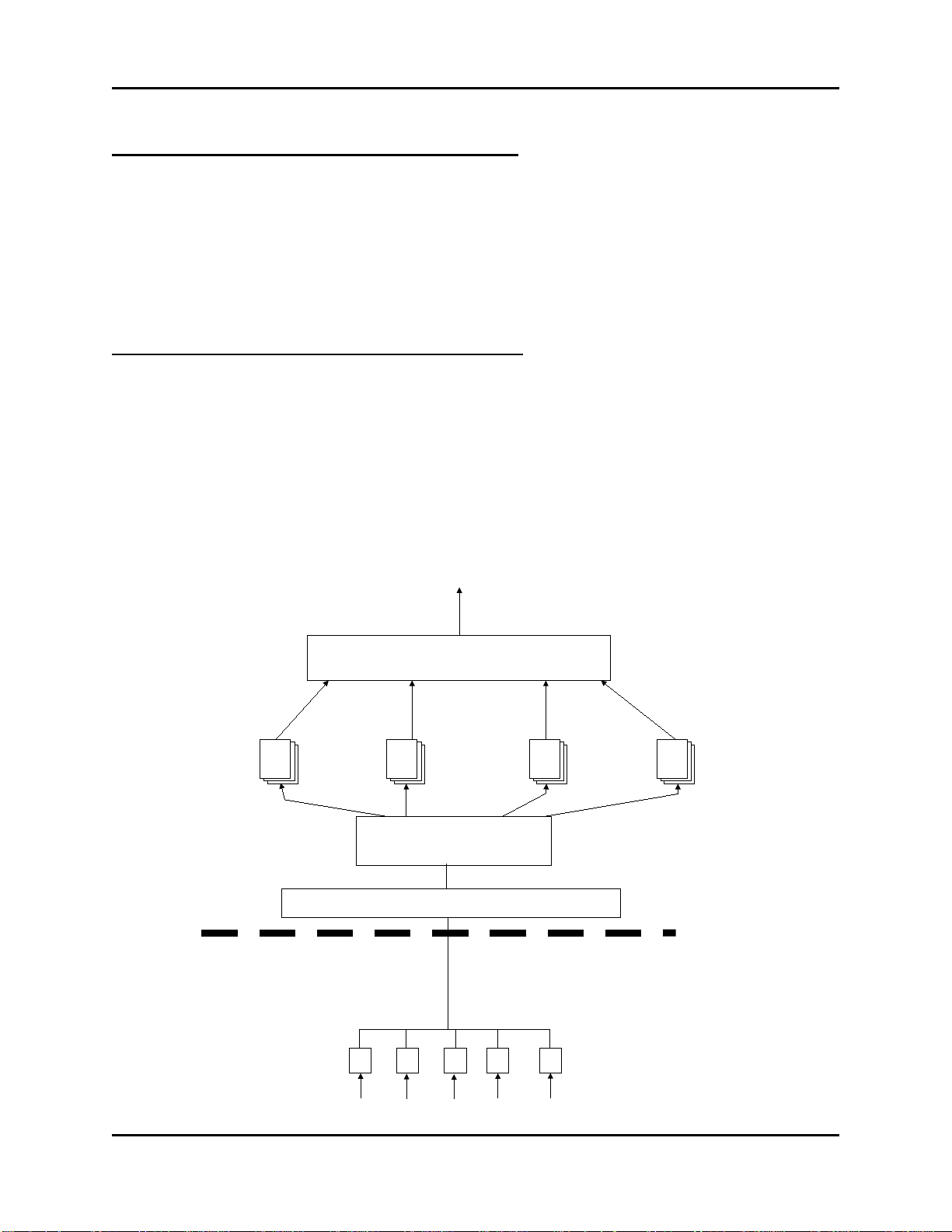
Introduction - What is the Harvester?
PC workstation running
Open BSI and Harvester
software (plus HMI software
e.g. OpenEnterprise)
Radio connection
Cable or dial-up
connections
Network 3000 Flow
computers/correctors
Network 3000
controller
Network 3000
controller
Network 3000
controller
ControlWave
controller
ControlWave
controller
Introduction – What is the Harvester?
The Harvester is a utility which allows collection of historical data from a network of
ControlWave and Network 3000 controllers. It combines many of the features of the OpenBSI
Scheduler and OpenBSI Data Collector programs, available in earlier releases of OpenBSI.
What types of data can be collected?
This historical data which can be collected by the Harvester includes:
• Data array values
• Archives
• Audit data (alarms and/or events)
• Lists (typically containing configuration data)
The Harvester can be used with Network 3000 series controllers (DPC 3330, TeleFlow, etc.) as
well as the ControlWave series of controllers.
1 OpenBSI Harvester
Introduction - What is the Harvester?
Controller
Network
Communication Link
(direct cable connection,
dial-up modem, or radio)
Inputs from field instrumentation
Open BSI Communications Layer
PC
Harvester
Array
data
files
Archive
data
files
Audit
data
files
List
data
files
Data File Conversion Utility
Export to OpenEnterprise,
Access, Excel, etc.
What determines how often data is collected?
Data can be collected at scheduled intervals e.g. hourly, or at a specified set of up to ten times
during the day, or based on a pre-defined collection scheme which takes into account various
factors affecting communications.
OpenBSI communications must be active for collections to occur.
What happens to the data once it is collected?
The data collected by the Harvester is stored in files at the PC workstation. These files can be
converted to a variety of formats using the OpenBSI Data File Conversion Utility, making them
accessible to other programs:
• OpenEnterprise database
• Comma Separated Variable format (CSV) - for use in Microsoft® Excel
• Coastal Flow Measurement's Flow-Cal™ package
• ODBC - for use in Microsoft® Access
OpenBSI Harvester 2

Introduction - What is the Harvester?
NOTE:
which simplify data management, and make data collection more efficient.
Overview of Steps Which Must be Completed to Successfully Use the Harvester
1. The OpenBSI Network Edition, and the Harvester kit must be installed on your PC
workstation. In addition, if this is a new system, you will need the ControlWave Designer
kit, and/or the ACCOL Workbench kit, to create a control strategy which will execute in
the controller.
2. Create structures in your control strategy which will hold the data you want to collect
with the Harvester. These structures can include lists, arrays, archives, or audit trail. You
may find it advantageous to use the same signal names, list numbers, array numbers, and
archive numbers in each controller you configure, since this can simplify your
configuration activities later on.
We strongly recommend you consider using Archives instead of Arrays, because
Archives are more versatile. Archives include sequence numbers and timestamps
3. Create necessary configuration signals in each control strategy. These are used for modem
control, and to set various modes of operation for the controller, when it is used with the
Harvester. Again, you may find it advantageous to use the same configuration signal
names in each controller.
4. Download the completed and compiled control strategy files (ACCOL or ControlWave)
into each controller.
5. Configure your controller network. Before attempting to use the Harvester, you must have
an existing network of controllers to communicate with. These controllers must exist in
your NETDEF database. Verify that communications between the PC and the controller
network are functioning properly before trying to configure and use the Harvester.
6. Start the Harvester software, and sign on.
7. If you used lists with the same list numbers and signal names, you can configure common
lists at this point, otherwise, skip this step.
8. Add new node(s), and configure the node(s) using the Node Configuration pages, and the
Collection Configuration dialog box.
9. Edit the system information to specify the locations where Harvester files should be
output, and if you are using the scan interval for your on-time method, specify its
associated parameters.
3 OpenBSI Harvester

Introduction - What is the Harvester?
10. Examine the status of your collections in the monitor window.
11. Configure the OpenBSI Data File Conversion Utility to set up export of the Harvester
data files to formats which may be exported to OpenEnterprise or various third-party
packages.
OpenBSI Harvester 4

Installing the Softw are
Installing the Softw are
The Harvester software is included on the OpenBSI CD-ROM.
To install it, choose “Install OpenBSI” from the choices provided in the CD browser, and then
select “Harvester”. If it isn’t already installed, you should also select “Network Edition”.
Continue with the installation by following the directions onscreen. For more information on the
installation process, and on other software packages, see Chapter 2 of the OpenBSI Utilities
Manual (document# D5081).
5 OpenBSI Harvester

Configuring Your Controller
Configuring Your Controller to Work with the Harvester
Before attempting to use the OpenBSI Harvester, your controller network must already be 'up and
running', and collecting data from field instrumentation. Instructions for setting up each
controller are included in the hardware manual accompanying the device.
The node name for each and every controller must exist in the Network Definition (NETDEF)
files. During later stages of configuration, you will need to know the node name, local address,
and expanded node addressing group number (if applicable) for each controller.
EGM 3530-10A, EGM 3530-50A TeleFlow™ Users
If you are using an EGM 3530-10A or -50A TeleFlow™ electronic gas measuring computer, it is
already pre-configured with the required signals, signal lists, Audit Trail, and archive structures;
if you need to alter the configuration, please contact our Technical Support Group for assistance.
DPC 3330, DPC 3335, RTU 3305, RTU 3310, 3530B-series, GFC 3308, ControlWave Users
If you are using Network 3000-series DPC 3330, DPC 3335, RTU 3305, RTU 3310, 'B' or newer
3530-series units supporting ACCOL, or a GFC 3308 unit, the ACCOL load running in the unit
must be configured with certain structures. Similar structures must also be created if you are
using a ControlWave controller running one of the IEC 61131 languages.
These structures (data arrays, the EAudit Module (or AUDIT function block for ControlWave),
signal lists, and signals) are discussed, briefly, below:
OpenBSI Harvester 6
Configuring Your Controller
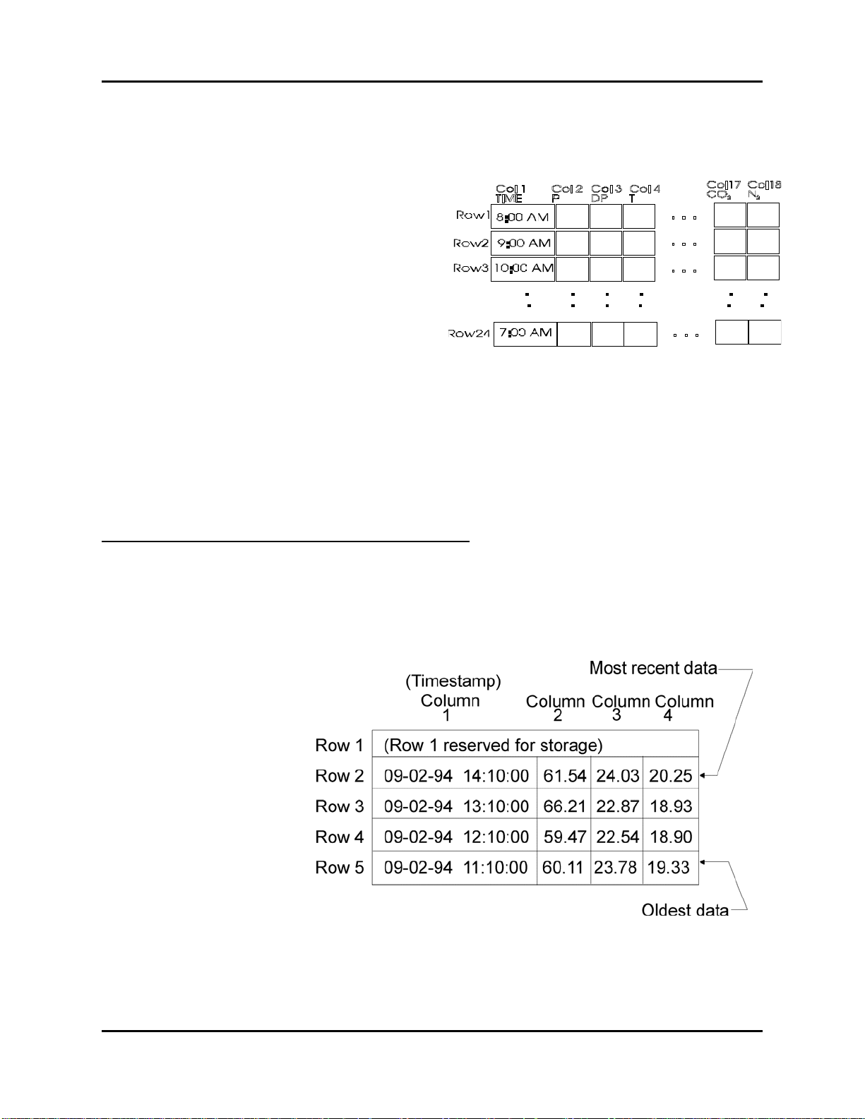
Data Arrays
The Harvester collects data from an analog readwrite data array, or from multiple such arrays
which share the same row/column dimensions.
These arrays are used to hold historical data.
In most cases, the first column of each analog
read-write array must contain a timestamp in the
Julian format of the ACCOL system signal
#TIME.000 or the ControlWave _TIME_000
variable.
The remaining columns of each array row contain the actual data collected at the time designated
by the timestamp in column 1. An example array is shown, above, which contains hourly flow
data from a natural gas pipeline. The type of data in the array will vary depending upon your
particular application.
There are four basic methods of array storage, each of which is discussed, below:
Storage without Wrapping (Push Down Array)
Storage without wrapping means that the most recent data is always stored in row 2 of the data
array; and as new data is entered, the previous data in row n is moved to row n+1, with the data
in the last row of the array discarded. (Note: Row 1 is reserved for temporary storage of running
totals.)
The pictures at right
illustrate this concept by
showing two snapshots of a 5
row by 4 column data array.
In the first picture, the most
recent data has a time stamp
of September 2, 1994 at 2:10
PM and is in row 2.
7 OpenBSI Harvester
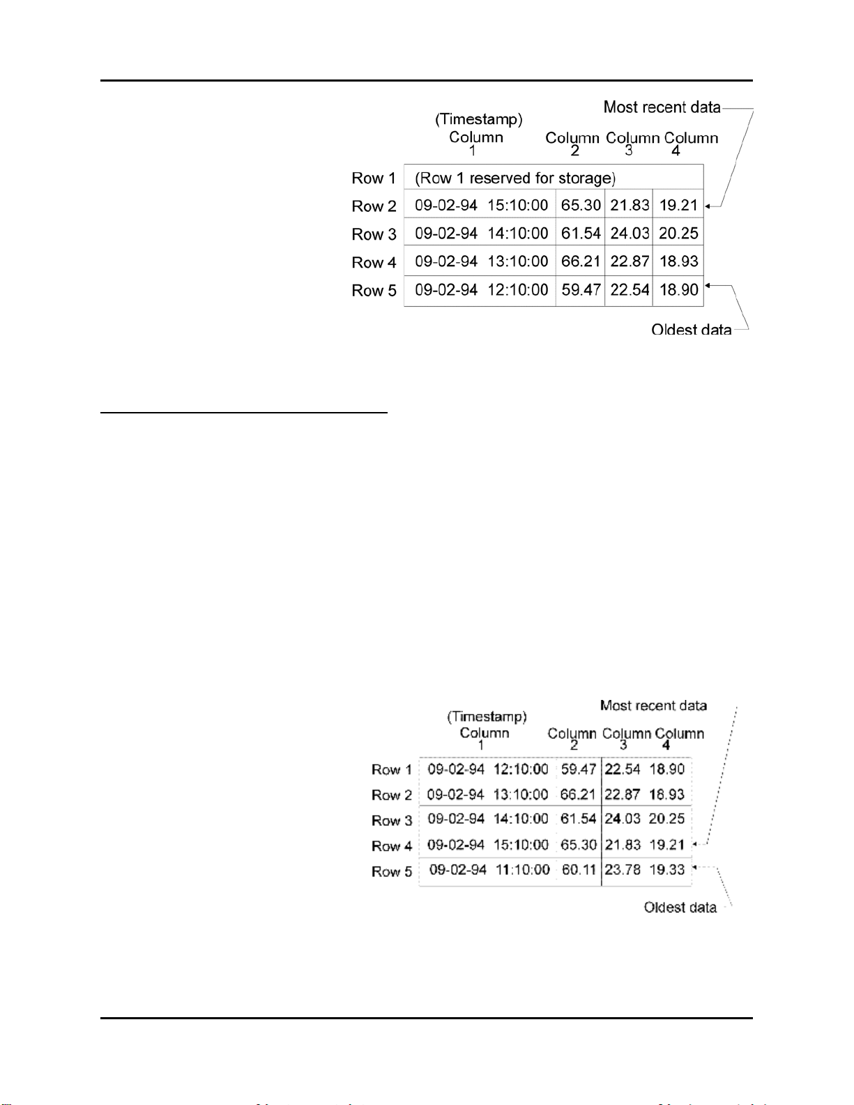
Configuring Your Controller
In the second picture, new data has
been collected, at 3:10 PM,
pushing the 2:10 PM data down
into row 3, the row 3 data into row
4, and the row 4 data into row 5.
The previous data that had been in
row 5 is discarded.
Storage with Wrapping (Wrap Array)
Storage with wrapping means that if the most recent data is currently in row n of the data array,
the next data will be stored in row n+1, unless row n is the last row of the array, in which case,
the next data will go to row 1. This wrap-around method is also referred to as a 'circular' array.
In this way, the oldest data is always overwritten with the newest data. When configuring this
array, data should always be stored beginning with Row 1. In addition, data must be stored in the
array at regular intervals, which are less than or equal to the specified scan interval. (Scan
intervals are discussed later in this manual.)
The pictures, below, illustrate the wrap array concept by showing three snapshots of a 5 row by 4
column data array.
In the first snapshot, the most recent
data has a time stamp of September 2,
1994 at 3:10 PM and is in the fourth
row.
OpenBSI Harvester 8

Configuring Your Controller
In the second picture, new data has
been collected, at 4:10 PM,
overwriting the oldest data (i.e.
11:10 AM data which had been in
row 5). The 12:10 PM data in row 1
is now the oldest.
In the third picture, new data is
collected again. It would be stored
in Row 6, except there isn't one, so
the array wraps-around and it is
stored in Row 1. Now the oldest
data, which was the 12:10 PM data
in row 1, has been over-written
with the most recent data, from
5:10 PM. The next collection will
overwrite Row 2, and so on.
Storage in Wrap Multiple Arrays
The final method of data array storage is typically used in applications involving large amounts
of data, such as gas flow metering, using the GFC 3308 AccuRate Gas Flow Computer with its
standard ACCOL load. In this type of application, arrays in the GFC 3308 unit's ACCOL load are
configured to store data on an hourly basis, and each array has 24 rows, one for each hour in the
24 hour period corresponding to a 'gas day.' When the gas day ends, i.e. the first array is full, new
data is stored in another array, until that array is full, and then still another array is used. (See the
figure, below.)
9 OpenBSI Harvester

Configuring Your Controller
IMPORTANT
rd ACCOL load for the GFC 3308, or you
create a load of your own, remember that multiple array collection can only
be performed if each and every array to be collected has th e exact sam e row /
izes through
multiple collection will cause the Harvester to terminate its collection. In
addition, when multiple arrays are to be collected, they must be numbered
This process continues until some pre-defined number of arrays has been filled, at which time,
the process will start over again. (This is similar to the wrapping discussed earlier, except instead
of wrapping around within a single array, wrapping occurs to another array.) When configuring
these arrays in ACCOL, data should always be stored beginning with Row 1 of the first array.
When wrapping to another array, storage should also always begin with Row 1. Data must be
stored at regular intervals, which are less than or equal to the specified scan interval.
If you decide to modify the standa
column dimensions. Any attempt to collect arrays of different s
consecutively.
Raw Array
A Raw Array collection involves an array where the Harvester simply collects the entire array,
without regard to timestamps, or rows.
No matter which of the methods are used, the Harvester will collect the historical data from the
data arrays, at a pre-defined scan interval, and store the data in files on the PC hard disk.
Archive Files
As an alternative to using data arrays, some controllers support the use of historical archive files.
Archive files reside within the controller, and are similar to data arrays, except that each column
is directly associated with a particular signal, and each column also has a descriptive title. See the
'ARC_STORE' section of the ACCOL II Reference Manual (document# D4044) for details.
ControlWave users should see the ControlWave Designer on-line help for the ‘ARCHIVE’
function block.
Wherever possible, we strongly recommend you use Archive Files for your historical storage.
NOTE: When using the Harvester to collect Archive Files in a BSAP network, the archive
records to be displayed must be 220 bytes or less. This is explained in more detail later in this
manual.
OpenBSI Harvester 10

Configuring Your Controller
EAudit Module, Audit Function Block
ACCOL users must configure the Extended Audit Trail Module (EAudit).1 This module is used
to record alarm and event conditions, and is discussed in detail in the 'Audit Trail /EAudit'
section of the ACCOL II Reference Manual (document# D4044.) Similarly, ControlWave users
must configure the AUDIT function block. See the ControlWave Designer on-line help in
ControlWave Designer for details.
The alarm/event data is collected by the Harvester, and stored in files on the PC hard disk.
Signal Lists, Conf iguration Signal List
The Harvester can collect signal lists. One of these lists may be the Configuration Signal List
which contains any configuration parameters related to your particular application. The
configuration list generally contains information which does not change often, because it is
normally collected only on system startup, if a change occurs, or if the operator explicitly
requests that it be collected. In a natural gas pipeline application, for example, this list might
contain signals whose values represent pipe diameters, or orifice types.
NOTE: Signal lists collected via the Harvester cannot have more than 1000 signals.
Radio Turn ON Time Logic
If you are using radios as your communication link, your program must include user-defined
logic to turn ON its radio, at a pre-determined time, so as to be ready for data collection from the
Harvester. This pre-determined time is calculated based on the node's local address, its expanded
node addressing group number, and various parameters defined in the Harvester. Appendix C of
this manual includes a sample ACCOL task which may be used to turn on a Network 3000
controller's radio at a scheduled time. For information on the turn on logic for the Harvester
program, see the box, below:
1
Protected mode firmware (PLS00/PLX00 or newer) currently only supports use of the EAudit Module. 186-based
units (except for the 3308) with AL (or newer firmware) or 386EX Real Mode units with RMS02 (or newer
firmware) can be used with either the Audit Module, or the EAudit Module.
11 OpenBSI Harvester

Configuring Your Controller
Calcul ati on of N ode Turn ON Time, A ctu al Colle ct i on Time
Turn ON T im e = Start T ime Off set + ([ Loc al Address - 1] * Poll Tim e Per Node)+
(Expanded Node Addressing G roup N o.)* (Po ll Time Per Group )
A ctual Start o f Co llec tio n = Turn ON Time + T urn on Delay
So, f or example, if:
Start Time O f fset = 1 se cond
Poll Time Per No de = 20 seconds
Poll Time Per Group = 5 sec onds
Turn on D elay = 5 se conds
Then, the c o ntro ller w ith the group # and local address # show n, will turn ON at
the time w ithin the scan interval shown:
Gro up #
L ocal A ddress #
Turn ON time
A ctual Start of
Collection
0 1 1 second 6 seconds
0 2 21 seco nds 26 seconds
0 3 41 seco nds 46 seconds
1 1 6 seconds 11 seconds
1 2 26 seco nds 31 seconds
1 3 46 seco nds 51 seconds
2 1 11 seco nds 16 seconds
2 2 31 seco nds 36 seconds
2 3 51 seco nds 56 seconds
Logical Signals t o Re gulate Data Collection & Modem Control
In addition to the signals collected via the signal lists, and turn ON time logic, each program
requires certain logical signals which are either used to notify the Harvester to perform a certain
function, or are used by the Harvester, to indicate it has performed a certain function. These
signals are as follows:
OpenBSI Harvester 12

Configuring Your Controller
Communications Off Signal
This signal is turned ON by the Harvester to notify the controller that it has finished collecting
data for this scan interval. This can trigger user-defined logic which turns OFF the radio.
Maintenance Mode Signal
This signal is set ON by the Harvester monitor as a notification that the radio should not be
turned OFF, even if no collections are currently occurring. (This might be done so maintenance
or testing can be performed.)
Force List Collection Signal
This signal is set ON by user-defined logic in the program as a notification to the Harvester that
the configuration list has changed, somehow, and so it should be re-collected by the Harvester.
This signal MUST be designated for audit trail collection via the EAudit Module or AUDIT
function block.
Modem Control Signals
If the Harvester is collecting data from a slave controller which communicates to its master
controller in the network via a dial-up modem, the master must have a pair of logical (boolean)
signals for modem control. One signal is turned on by the Harvester (Request signal) to signify
that the master controller should dial-up its slave controller. The second signal (Confirm signal)
is turned on by the master controller to indicate that the dial-up connection with the slave node
has been established, thereby signifying to the Harvester, that collections can begin.
13 OpenBSI Harvester

Starting the Harvester
r
r
r
Starting the Harvester
In order to start the Harvester, communications with the controller network must already be
active, via NetView. To start the Harvester, click as follows: StartProgramsOpenBSI
Tools Collection ProgramsHarvester
IMPORTANT: If this is the very first time the Harvester has been started
on this particular computer, you will be prompted to register the software.
Otherwise, the software can only be used for a maximum of 60 days. For
more information on the registration process, see Chapter 2 of the OpenBSI
Utilities Manual (document# D5081).
The Harvester Main Page will appear, as shown below:
Menu ba
Timestamp associated with most
recent collection
These sections of the screen
allow you to monitor information
about the status of the currently
configured collections.
Tool ba
Tree of
configured
controllers
Status ba
This window pane can display either a list of the active
nodes (controllers for which collections are occurring
right now) or a list of nodes which are in Maintenance
Mode, or a list of nodes which are experiencing
communication problems, or any current Harvester
debugging messges. You can select which items are
displayed either from icons in the tool bar or from the
“View” menu bar selection.
OpenBSI Harvester 14

Defining Common Lists
Defining Common Lists
If you are running an identical application load/project in more than one controller, that contains
signals you want to collect, you can use Common Lists to simplify your collections. A common
list is just a group of signals you want to collect, in which the signals share the same name in
more than one controller. For example, if you have ten controllers, and each one has signals
named CURRENT.FLOW, CURRENT.TEMP, and CURRENT.PRESUR that you want to
collect, you could define a Common List containing these three signals. The advantage is that the
Common List is defined in only one place (the Harvester program itself); so as long as those
individual signals already exist in the your running application, you don’t need to modify your
application to add or change the Common List. Another advantage of using common lists is that
you save on certain communications overhead, because signal names do not need to be collected,
just the signal values.
To access the Common List Configuration dialog box, click on Edit Common Lists.
To create a common list, click on the [Add List] button.
The Enter Common List Number dialog box will appear.
Enter a number which will identify the common list, then
click on [OK].
15 OpenBSI Harvester

Defining Common Lists
That list number will now appear in the "List" window on the left side of the Common List
Configuration dialog box. Click on it, and then click on either the [Insert After] or [Insert
Before] buttons to begin inserting signal names in the list.
The Enter Common List
Signal Name dialog box will
appear. Enter the name of the
first signal of the list, and
click on [OK].
That signal name will now appear in the "Signals" window on the right side of the Common
List Configuration dialog box. Repeat this process, using the [Insert After] button to insert
additional signals in the list. NOTE: The signal names and ordering of signals must match
exactly the corresponding signals in the controller's signal list.
The common list you define can be used, later, when you are defining a Signal List collection in
the Collection Configuration dialog box.
Changing a signal Name already in a Common List
To change the signal name of a signal already in the list, click on the signal, then click on the
[Modify] button. The Enter Common List Signal Name dialog box will re-appear, and you can
edit the signal name.
Deleting a signal Name already in a Common List
To delete the signal name of a signal already in the list, click on the signal, then click on the
[Delete] button. The signal name will be removed from the list.
Deleting an entire Common List
To delete an entire common list, click on the number of the list, in the "List" window of the
Common List Configuration dialog box, then click on the [Delete List] button.
Exiting the Common List Configuration dialog box
To exit the Common List Configuration dialog box, click on the [Close] button.
OpenBSI Harvester 16

Adding a Controller and Configuring Collections
First, select one of the controllers in this list. (This
Next, if configuration
Finally, click on [Add]
Adding a Controller and Configuring Collections
Before data can be collected from a controller, it must be added into the list of nodes accessible
by the Harvester, and certain configuration entries must be made.
Adding the Controller
To add a controller, click on the 'New Node' icon, shown above, or click on File New Node
from the menu bar. The Add Nodes dialog box will appear.
list is all controllers in your NETDEF file which have
NOT yet been defined in the Harvester.)
details for the controller
(e.g. numbers of structures
used in the collections,
configuration signals, etc.)
are identical with a
controller you already
defined, choose that
controller’s name from the
“Default Config” list box.
to bring up the Node
Configuration pages.
17 OpenBSI Harvester

Adding a Controller and Configuring Collections
• The "New Nodes" list box, displays a list of all controllers in your NETDEF database which
have NOT yet been configured for use with the Harvester. Select any one of these controllers
by clicking on it.
• Optionally, you can add multiple controllers at the same time by holding down the [Ctrl] key
as you select. This will cause all of the controllers you add to have the same collection
configuration parameters (you can alter them individually, after the initial configuration is
complete.) When you add multiple controllers via this method, you will prompted to enter an
"Auto Increment" value (in seconds).
If your collection method is 'Time
Interval', the "Auto Increment" is
used to space out collections if
collections from multiple
controllers are scheduled to occur
within the same interval.
(Otherwise the Harvester would
attempt to collect all the collections
at the same time, which could cause
communication problems.)
You can adjust the offset for individual nodes, later using the "Offset in seconds" parameter
described on page 23.
• Optionally, if you have already configured another controller with a similar configuration (for
example, it shares the same configuration signal names, and will use the same list, array
numbers, etc.) you can select its name from the "Default Config" list box. Once you have
selected a default configuration, common configuration details will be used for the new
controller you are adding.
• Finally, click on the [Add] button.
The Node Configuration pages will now appear. These pages allow you to enter various
configuration details, to choose how often your Harvester collections will be performed, and to
specify the type(s) of data to be collected by the Harvester from this particular controller.
OpenBSI Harvester 18

Adding a Controller and Configuring Collections
Node
Enter a textual description of the node. For example, 'OAK
characters you enter will be displayed as the description.
Disable Collections
When checked, the Harvester will NOT attempt to make any
Skip Historical Collections
When checked, the Harvester will NOT attempt to perform an
Turn Off Polling after
Normally, if communications with a particular controller are via a
collections, polling would be turned off, and the modem would be
Node Configuration - General Page
The Node Configuration pages appear immediately after you add a new controller.
Identification
STREET COMPRESSOR STATION'. This will appear in the
Harvester "Node Information" window. Only the first 64
Flags
collections from this controller. This would typically be checked
if a controller has been temporarily taken out of service for
repairs, or if there are communication problems which must be
fixed prior to attempting collections.
on First Pass
initial array / archive collection on startup. Instead, it will wait for
the next calculated interval.
Collections
dial-up modem or radio, as soon as the Harvester completes its
19 OpenBSI Harvester

Adding a Controller and Configuring Collections
hung up, because there is no reason to continue requesting data. If
Write to Station File
When checked, will automatically update the station file used by
to update the station file.
Communications Off
This signal is turned ON by the Harvester to notify the controller
Maintenance Mode Signal
This signal is set ON by the Harvester as a notification that the
Force List Collection
This signal is set ON by user-defined logic in the program as a
Username
RESERVED FOR FUTURE USE.
Password
RESERVED FOR FUTURE USE.
this box is NOT checked, however, polling will continue, even
after a collection has been completed. This can be useful if the
controller has a direct cable connection (i.e. it is always
connected.)
the OpenBSI Data File Conversion Utility. If no station file exists,
one will be created. NOTE: If there are multiple list, arrays, etc.
being collected from this controller, only the first one will be used
Communications Signals
Signal
Signal
ControlWave Security
Modem Control
If the Harvester is collecting data from a slave controller which communicates to its master
controller in the network via a dial-up modem, the master must have a pair of logical (boolean)
signals for modem control.
The Harvester will turn on the request signal, which should be used as a notification to execute
user-defined logic in the master for dialing up the slave node. When this is successfully done, the
user-defined logic should set the confirm signal to ON, as a notification to the Harvester that
collections from the slave node can proceed. The Harvester will check the confirm signal at a
OpenBSI Harvester 20
that it has finished collecting data for this scan interval. This can
trigger user-defined logic which turns OFF the radio.
radio should not be turned OFF, even if no collections are
currently occurring. (This might be done while maintenance or
testing is being performed.)
notification to the Harvester that the configuration list has
changed, somehow, and so it should be recollected by the
Harvester. This signal MUST be designated for audit trail
collection via the EAudit Module or AUDIT function block.

Adding a Controller and Configuring Collections
Request Signal
The Harvester turns on the "Request Signal" in the Master node, to activate
Confirm
User-defined logic in the control strategy file must turn this signal on to notify
Retries
After setting the "Request Signal", this is the number of times the Harvester
Confirm Wait
After setting the "Request Signal", this is the length of time (in seconds) the
user-specified interval (see "Confirm Wait" and "Retries", below).
Signal
user-defined logic in the control strategy file, that will initiate a dial-up
operation to the Slave node.
the Harvester that the Slave node has been successfully dialed, and collections
can commence.
will check to see that the "Confirm Signal" has been turned ON.
Harvester will wait before checking to see that the "Confirm Signal" has
been turned ON. This same period applies to all "Retries" as well.
21 OpenBSI Harvester
Adding a Controller and Configuring Collections
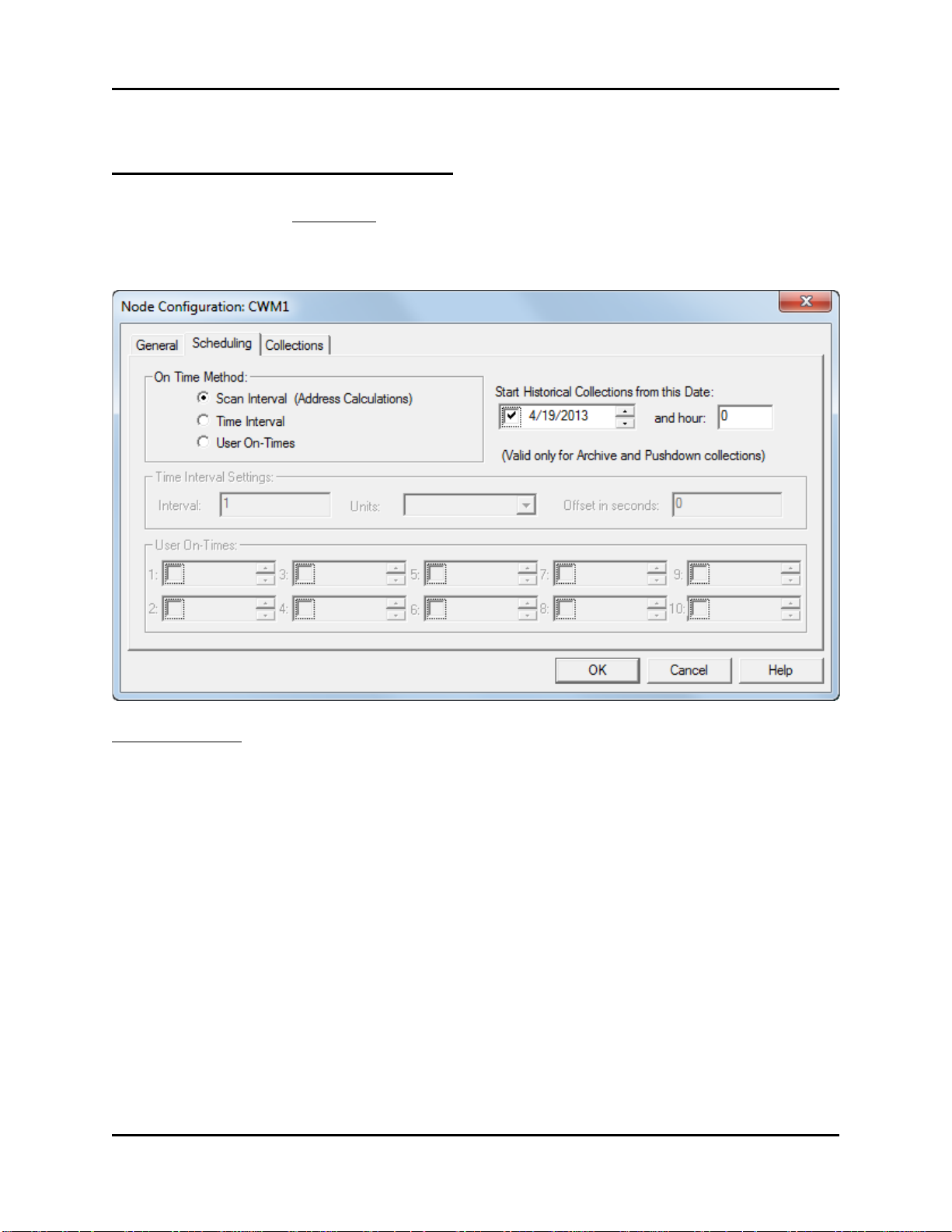
Scan Interval (Address
When this is chosen, the Harvester attempts to
Time Interval
When this is chosen, the Harvester attempts to
User On-Times
When this is chosen, the Harvester attempts to
below.
Node Configuration - Scheduling Page
NOTE: If you are using Distributed User On-Times (different from ‘User On-Times’ shown
below) skip the ‘Scheduling’ page. Distributed User On-Times is discussed later in this manual
in the ‘Specifying Distributed User On-Times’ section.
On Time Method
Only one On Time Method per controller may be used. There are three possible choices:
Calculations)
OpenBSI Harvester 22
communicate with a particular node based on its location
in the network, as determined by an address calculation.
communicate with a particular node every time a
particular period of time has expired, for example, every
hour. See "Timer Interval Settings" below.
communicate with a particular node at up to ten specified
times during the day. See the "User On-Times" section,

Adding a Controller and Configuring Collections
Start Historical Collections from
If you have several days of pushdown array or archive
and hour
If you want to specify that this historical data that you
23). (Requires OpenBSI 5.9 or newer)
Interval
Together with the "Units" this defines the period of time between
Units
This defines the units of the interval. The possible choices are 'minutes',
Offset in seconds
This specifies a period of time in seconds (measured from the beginning of
occur within the same interval.
First, check this box
Now click on any part of
arrows to adjust the date.
Optionally specify a different
this Date:
data stored in the controller, this allows you to specify
the first date from this historical data from which you
want the collections to begin. Any stored data for dates
earlier than this will not be collected. (This applies only
to Archive and pushdown arrays.)
the date and type a new
date, or optionally use the
hour than midnight here.
To set the date, check the box next to the date, then
select one of the date fields, and either enter new
numbers for the date, or use the up-down controls on the
right to adjust the date as desired.
collect doesn’t start at the default of midnight (0) you
can specify a different hour here (in 24 hour format 0-
Time Interval Settings
collections. For example, if the "Interval" is set to 1, and "Units" is set to
'hours', then collections will occur every hour.
'hours' or 'days'.
the interval) that the Harvester will wait before beginning its collection. This
is often necessary if arrays or archives are being updated in the controller
every hour, and it is necessary to wait this number of seconds for the array /
archive manipulation to be completed. If left at 0, the collection will begin at
the very start of the interval. The offset can also be used to space out
collections, if several collections from multiple controllers are scheduled to
23 OpenBSI Harvester

Adding a Controller and Configuring Collections
First, check this box
Now cl ick on any part o f
the time and type a new
time, or optionally use the
arrows to adjust the time.
User On-Times
If User On-Times is selected as the On-Time Method, up to 10 different times during the day can
be specified as times at which the Harvester should collect data from this controller. Use the
"User On-Times" boxes, shown, to specify a time for collection.
NOTE: If you have a large number of controllers, and do not want to manually enter on times for
each one, you can use an alternate method called Distributed User On-Times. This is discussed
later in this manual in the ‘Specifying Distributed User On-Times’ section.
Reducing Communication Message Traffic (OpenBSI 5.8 Service Pack 1 and newer only):
By default, Harvester collects column header information each collection pass. To prevent this
re-collection of column header data and thereby reduce the number of communication messages
per collection, you can use the Advanced Configuration tool to turn off re-collection of column
header information. This option can reduce communication costs if your communication link is
expensive, for example a satellite link.
To do this:
1. First start the Advanced Configuration tool by clicking OpenBSI Tools > Common
Tools > Advanced Configuration.
2. Then on the Harvester tab of the OpenBSI INI Configuration Settings dialog box, check
the “Do Not collect Column Header Information on Archive Collections” and click
“OK”. Harvester will not collect column header information on subsequent collections.
OpenBSI Harvester 24
 Loading...