

Remote Automation Solutions IEC 62591 Wireless Interface Instruction Manual Manuals & Guides
Page 1

Part Number D301708X012
October 2021
IEC 62591 Wireless Interface Instruction
Manual (for ROC800-Series and FloBoss™
107)
Remote Automation Solutions
Page 2

IEC 62591 Wireless Interface Instruction Manual (for ROC800-Series and FloBoss 107)
Device Safety Considerations
Reading these Instructions
Before operating the device, read these instructions carefully and understand their safety implications. In some situations,
improperly using this device may result in damage or injury. Keep this manual in a convenient location for future reference.
Note that these instructions may not cover all details or variations in equipment or cover every possible situation regarding
installation, operation, or maintenance. Should problems arise that are not covered sufficiently in the text, immediately
contact Customer Support for further information.
Protecting Operating Processes
A failure of this device – for whatever reason -- may leave an operating process without appropriate protection and could
result in possible damage to property or injury to persons. To protect against this, you should review the need for additional
backup equipment or provide alternate means of protection (such as alarm devices, output limiting, fail-safe valves, relief
valves, emergency shutoffs, emergency switches, etc.). Contact Remote Automation Solutions for additional information.
Returning Equipment
If you need to return any equipment to Remote Automation Solutions, it is your responsibility to ensure that the equipment
has been cleaned to safe levels, as defined and/or determined by applicable federal, state and/or local law regulations or
codes. You also agree to indemnify Remote Automation Solutions and hold Remote Automation Solutions harmless from
any liability or damage which Remote Automation Solutions may incur or suffer due to your failure to ensure device
cleanliness.
Grounding Equipment
Ground metal enclosures and exposed metal parts of electrical instruments in accordance with OSHA rules and regulations
as specified in Design Safety Standards for Electrical Systems, 29 CFR, Part 1910, Subpart S, dated: April 16, 1981 (OSHA
rulings are in agreement with the National Electrical Code). You must also ground mechanical or pneumatic instruments
that include electrically operated devices such as lights, switches, relays, alarms, or chart drives.
Important: Complying with the codes and regulations of authorities having jurisdiction is essential to ensuring personnel
safety. The guidelines and recommendations in this manual are intended to meet or exceed applicable codes and
regulations. If differences occur between this manual and the codes and regulations of authorities having jurisdiction, those
codes and regulations must take precedence.
Protecting from Electrostatic Discharge (ESD)
This device contains sensitive electronic components which be damaged by exposure to an ESD voltage. Depending on the
magnitude and duration of the ESD, it can result in erratic operation or complete failure of the equipment. Ensure that you
correctly care for and handle ESD-sensitive components.
System Training
A well-trained workforce is critical to the success of your operation. Knowing how to correctly install, configure, program,
calibrate, and trouble-shoot your Emerson equipment provides your engineers and technicians with the skills and
confidence to optimize your investment. Remote Automation Solutions offers a variety of ways for your personnel to
acquire essential system expertise. Our full-time professional instructors can conduct classroom training at several of our
corporate offices, at your site, or even at your regional Emerson office. You can also receive the same quality training via our
live, interactive Emerson Virtual Classroom and save on travel costs. For our complete schedule and further information,
contact the Remote Automation Solutions Training Department at 800-338-8158 or email us at education@emerson.com
Ethernet Connectivity
This automation device is intended to be used in an Ethernet network which does not have public access. The inclusion of
this device in a publicly accessible Ethernet-based network is
not recommended.
System Training
A well-trained workforce is critical to the success of your operation. Knowing how to correctly install, configure, program,
calibrate, and trouble-shoot your Emerson equipment provides your engineers and technicians with the skills and
confidence to optimize your investment. Remote Automation Solutions offers a variety of ways for your personnel to
acquire essential system expertise. Our full-time professional instructors can conduct classroom training at several of our
corporate offices, at your site, or even at your regional Emerson office. You can also receive the same quality training via our
live, interactive Emerson Virtual Classroom and save on travel costs. For our complete schedule and further information,
contact the Remote Automation Solutions Training Department at 800-338-8158 or email us at education@emerson.com.
.
iv Revised October 2021
Page 3

IEC 62591 Wireless Interface Instruction Manual (for ROC800-Series and FloBoss 107)
Contents
Chapter 1 – General Information 1-1
1.1 Overview ........................................................................................................................................ 1-1
1.2 Scope of Manual ............................................................................................................................ 1-2
1.3 Hardware ........................................................................................................................................ 1-2
1.3.1 IEC 62591 Wireless Interface Module ............................................................................... 1-2
1.3.2 Emerson Wireless 781S Smart Antenna ........................................................................... 1-3
1.3.3 WirelessHART Field Devices ............................................................................................. 1-4
1.4 Configuration/Commissioning Software (Field Tools) .................................................................... 1-4
1.5 Additional Technical Information .................................................................................................... 1-5
Chapter 2 – Installation 2-1
2.1 Installing the IEC 62591 Module .................................................................................................... 2-1
2.2 Installing the Wireless 781S Smart Antenna .................................................................................. 2-3
2.2.1 Optimizing the Location ...................................................................................................... 2-3
2.2.2 Positioning the 781S .......................................................................................................... 2-4
2.2.3 Mounting the 781S ............................................................................................................. 2-4
2.2.4 Grounding the 781S ........................................................................................................... 2-5
2.3 Wiring the Module and 781S .......................................................................................................... 2-5
2.3.1 Wiring the 781S .................................................................................................................. 2-5
2.3.2 Wiring the IEC 62591 Module to the 781S ......................................................................... 2-6
2.4 Preparing for Configuration and Commissioning ........................................................................... 2-8
Chapter 3 – Configuration and Commissioning 3-1
3.1 Overview ........................................................................................................................................ 3-2
3.1.1 Configuring Devices and Planning the Network................................................................. 3-2
3.1.2 Network ID and Join Key .................................................................................................... 3-3
3.1.3 Rosemount THUM™ Adapter ............................................................................................. 3-3
3.2 IEC 62591 Module Interface (FB107) ............................................................................................ 3-4
3.2.1 Commissioning Devices ..................................................................................................... 3-8
3.2.2 Managing Device Information .......................................................................................... 3-10
3.2.3 Viewing Network Statistics ............................................................................................... 3-18
3.2.4 Retrieving a Diagnostic Log ............................................................................................. 3-20
3.2.5 Displaying Commissioned Transmitters ........................................................................... 3-21
3.3 IEC 62591 Module Interface (ROC800) ....................................................................................... 3-22
3.3.1 Accessing the Network ..................................................................................................... 3-24
3.3.2 Commissioning Devices ................................................................................................... 3-26
3.3.3 Managing Device Information .......................................................................................... 3-29
3.3.4 Viewing Network Statistics ............................................................................................... 3-36
3.3.5 Retrieving a Diagnostic Log ............................................................................................. 3-38
3.4 Updating Module Firmware .......................................................................................................... 3-39
3.4.1 Updating the IEC 62591 Module Firmware (ROC800/ FloBoss 107) .............................. 3-41
Chapter 4 – Troubleshooting 4-1
4.1 General Guidelines......................................................................................................................... 4-1
4.2 Common Troubleshooting Techniques .......................................................................................... 4-2
4.2.1 Identifying which System Components are Working ......................................................... 4-2
4.2.2 Conducting Basic Hardware Checks ................................................................................. 4-2
4.2.3 Looking for Possible Configuration Errors ......................................................................... 4-3
Revised October 2021 v
Page 4

IEC 62591 Wireless Interface Instruction Manual (for ROC800-Series and FloBoss 107)
4.2.4 Rebooting after a Power Loss ............................................................................................. 4-3
4.2.5 USB Flash Drive Not Recognized ....................................................................................... 4-3
4.3 Errors from the IEC 62591 Transmitter Tab .................................................................................... 4-3
4.3.1 NaN value ........................................................................................................................... 4-3
4.3.2 Stale / Communication Failure ............................................................................................ 4-4
Index I-1
vi Revised October 2021
Page 5

IEC 62591 Wireless Interface Instruction Manual (for ROC800-Series and FloBoss 107)
Chapter 1 – General Information
In This Chapter
1.1 Overview ............................................................................................1-1
1.2 Scope of Manual ................................................................................1-2
1.3 Hardware ...........................................................................................1-2
1.3.1 IEC 62591 Wireless Interface Module ................................1-2
1.3.2 Emerson Wireless 781S Smart Antenna ............................1-3
1.3.3 WirelessHART Field Devices ..............................................1-4
1.4 Configuration/Commissioning Software (Field Tools) .......................1-4
1.5 Additional Technical Information .......................................................1-5
1.1 Overview
This manual covers both the hardware – the IEC 62591 Wireless
Interface module for the Series 2 ROC800 RTU, the IEC 62591
Wireless Interface module for the FloBoss™ 107 flow computer, and the
Emerson™ Wireless 781S Smart Antenna (“781S”) – and the Field
Tools software you need to configure and commission the hardware
components.
Note: The IEC 62591 Wireless Interface uses open source software.
Refer to Open Source Software Listing document (included in
the same .zip file as this manual) for a complete listing of all
components. Source code is available upon request by contacting
Remote Automation Solutions’ Technical Support.
This chapter details the structure of this manual and provides an
overview of the IEC 62591 Wireless Interface and its components.
The International Electrotechnical Commission’s 62591 standard
(commonly called WirelessHART®) is a global IEC-approved standard
that specifies an interoperable self-organizing mesh technology in which
field devices form wireless networks that dynamically mitigate
obstacles in the process environment. This architecture creates a costeffective automation alternative that does not require wiring and other
supporting infrastructure.
Remote Automation Solutions IEC 62591implementation consists of an
IEC 62591 Wireless Interface module installed in a Series 2 ROC800 or
an FB107 device. The module is wired to a field-installed 781S. The
wiring powers the 781S and transmits signals between the 781S and a
number of field-installed WirelessHART devices. (Figure 1-1 shows a
ROC809/FB107, a 781S, and several WirelessHART devices.) The
ROC800 implementation supports up to 60 devices at a 4-second
communications rate, while the FB107 implementation supports up to
20 devices at a 2-second communications rate. Refer to the product data
sheets for each device for additional device/communication rate values.
Revised October 2021 General Information 1-1
Page 6

IEC 62591 Wireless Interface Instruction Manual (for ROC800-Series and FloBoss 107)
General Information
62591 Wireless Interface.
Figure 1-1. IEC 62591 Field Installation
1.2 Scope of Manual
This manual contains the following chapters:
Chapter 1
Chapter 2
Installation
Chapter 3
Configuring and
Commissioning
Chapter 4
Troubleshooting
1.3 Hardware
The IEC 62591 Wireless Interface has two basic components: the IEC
62591 Wireless Interface module (“module”) and the 781S.
Provides an overview of the hardware for the IEC
Provides information on installing the IEC 62591
Wireless Interface modules, installing the 781S, and
wiring the 781S to the module.
Provides information using ROCLINK 800 to
configure and commission the Wireless Interface.
Provides information on diagnosing and correcting
problems for the IEC 62591 Wireless Interface.
1-2 General Information Revised October 2021
1.3.1 IEC 62591 Wireless Interface Module
Functionally, there is no difference between the module for the FB107
and the module for the ROC800. Each module uses the same printed
circuit board (PCB) but has a slightly different plastic casing. See
Figure 1-2; the ROC800 module is on the left and the FB107 module is
on the right.
Page 7

IEC 62591 Wireless Interface Instruction Manual (for ROC800-Series and FloBoss 107)
USB Port
The module’s USB port supports firmware upgrades and provides
Figure 1-2. IEC 62591 Wireless Interface Module
You can place the module in any available slot on the ROC800 and in
any available slot on the FB107. However, each ROC800 or FB107 can
support only one IEC 62591 Wireless Interface module.
Note: For information on installing modules in the FB107, refer to the
FloBoss™ 107 Flow Manager Instruction Manual (Part
D301232X012). For information on installing modules in the
ROC800, refer to the ROC800-Series Remote Operations
Controller Instruction Manual (Part D301217X012).
debug information for product support. For further information, refer
to Chapter 3, Configuration and Commissioning.
Caution
Do not use the USB connector unless the area is known to be nonhazardous.
1.3.2 Emerson Wireless 781S Smart Antenna
The second component in the Wireless Interface is the 781S (see Figure
1-3). You install the 781S away from the controller in the optimal
location for best network performance. A 4-wire connection between the
module and the 781S provides the 24 Vdc power the 781S requires and
transmits communication signals sent to the 781S from the various
WirelessHART field devices.
Revised October 2021 General Information 1-3
Page 8

IEC 62591 Wireless Interface Instruction Manual (for ROC800-Series and FloBoss 107)
Figure 1-3. Emerson Wireless 781S Smart Antenna
For instructions on installing the 781S in the field, refer to Chapter 2,
Installation.
1.3.3 WirelessHART Field Devices
The two components of Remote Automation Solutions’ IEC 62591
Wireless Interface provide you with the ability to manage signals from a
network of WirelessHART field devices. The physical configuration of
the IEC 62591 Wireless Interface is based on the controller (FB107 or
ROC800) and the total number of field devices. A ROC800
implementation supports up to 60 devices, while a FB107
implementation supports up to 20 devices.
Remote Automation Solutions supports transmitters that conform to the
WirelessHART protocol. For a current list of the transmitters Remote
Automation Solutions has tested with the IEC 62591 Interface, refer to
the following product data sheets (available at
www.EmersonProcess.com/RemoteAutomation):
FloBoss
ROC800-Series IEC 62591 Interface (part D301712X012)
™
107 IEC 62591 Interface (part D301713X012)
1.4 Configuration/Commissioning Software (Field Tools)
Field Tools is a comprehensive software solution that folds several
Remote Automation Solutions configuration software tools –
ROCLINK™, ControlWave Designer, and TechView, among others –
into one point-of-access tool. Field Tools simplifies the process of
configuring both wired and wireless HART devices.
Once you have installed the IEC 62591 modules and wired them to the
781S, you use Field Tools to configure and then commission
(“activate”) the entire network. Refer to Chapter 3, Configuring and
Commissioning, for specific instructions.
1-4 General Information Revised October 2021
Page 9

IEC 62591 Wireless Interface Instruction Manual (for ROC800-Series and FloBoss 107)
Name
Part Number
ROC800-Series IEC 62591 Interface Product Data
Sheet
D301712X012
FloBoss™ IEC 62591 Interface Product Data Sheet
D301713X012
FloBoss™ 107 Flow Manager Instruction Manual
D301232X012
ROC800-Series Remote Operations Controller
Instruction Manual
D301217X012
1.5 Additional Technical Information
Refer to the following technical documentation (available at
www.Emerson.com) for additional technical and most-current
information:
Table 1-1. Additional Technical Information
Revised October 2021 General Information 1-5
Page 10

IEC 62591 Wireless Interface Instruction Manual (for ROC800-Series and FloBoss 107)
1-6 General Information Revised October 2021
Page 11

IEC 62591 Wireless Interface Instruction Manual (for ROC800-Series and FloBoss 107)
device and try again.
ROC800
To install a module in
If any processes require backup, arrange for that before removing
Chapter 2 – Installation
In This Chapter
2.1 Installing the IEC 62591 Module ...................................................... 2-1
2.2 Installing the Wireless 781S Smart Antenna ................................... 2-3
2.2.1 Optimizing the Location ........................................................ 2-3
2.2.2 Positioning the 781S ............................................................ 2-4
2.2.3 Mounting the 781S ............................................................... 2-4
2.2.4 Grounding the 781S ............................................................. 2-5
2.3 Wiring the Module and 781S ........................................................... 2-5
2.3.1 Wiring the 781S .................................................................... 2-5
2.3.2 Wiring the IEC 62591 Module to the 781S ........................... 2-6
2.4 Preparing for Configuration and Commissioning ............................. 2-8
This chapter describes installing the IEC 62591 module in either a
ROC800 or FB107, installing the Emerson Wireless 781S Smart
Antenna (“781S”), and connecting the 781S to the IEC 62591 Wireless
Interface module.
Note: This chapter covers the physical installation process. To
configure and commission the IEC 62591 Wireless Interface,
refer to Chapter 3, Configuring and Commissioning.
Caution
Module initialization can take up to five minutes. During this time,
module configuration is not possible and the USB port on the module
is not recognized. Attempting configuration before initialization is
complete may cause errors on your network. The module is initialized
when the Status field on the Network tab includes the word Online. If
network errors persist after module initialization, power cycle your
2.1 Installing the IEC 62591 Module
You install the IEC 62591 Wireless Interface module in a Series 2
ROC800 or an FB107 as you would any other module. However, you
can install only one IEC 62591 module in either device.
Caution
power from the device.
1. Remove power from the device.
the Series 2 ROC800:
2. Remove the wire channel cover.
Note: Leaving the wire channel cover in place can prevent the
module from correctly connecting to the socket on the
backplane.
Revised October 2021 Installation 2-1
Page 12

IEC 62591 Wireless Interface Instruction Manual (ROC800-Series and FloBoss 107)
FB107
To install a module in th
3. Perform one of the following:
If a module is currently in the slot, unscrew the captive screws
and remove that module. Store it in an anti-static bag.
If the slot is currently empty, remove and store the module
cover.
4. Insert the module through the module slot in the front of the
ROC800 or EXP housing. Make sure that the label on the front of
the module faces right side up (see Figure 1-2). Gently slide the
module in place until it contacts properly with the connectors on the
backplane.
Note: If the module stops and does not go any farther, do not force
the module. Remove the module and see if the pins are bent.
If the pins are bent, gently straighten the pins and re-insert
the module. The back of the module must connect fully with
the connectors on the backplane.
5. Tighten the captive screws on the front of the module.
Caution
Caution
6. Wire the module to the 781S (refer to Wiring the Modules and 781S
Link section in this chapter).
7. Replace the wire channel cover.
Never connect the sheath surrounding shielded wiring to a signal
ground terminal or to the common terminal of an I/O module. Doing so
makes the module susceptible to static discharge, which can
permanently damage the module. Connect the shielded wiring sheath
only to a suitable earth ground.
e FB107:
If any processes require backup, arrange for that before removing
power from the device.
1. Remove power from the device.
2. Perform one of the following:
If a module is currently in the desired slot, remove the module
and store it in an anti-static bag.
If the slot is currently empty, remove and store the module
cover.
2-2 Installation Revised October 2021
Page 13

IEC 62591 Wireless Interface Instruction Manual (for ROC800-Series and FloBoss 107)
Note: When you install an IEC 62591 module in the FB107’s slot
2, the firmware redirects the COM2 communications port on
the CPU to the module installed in slot 2. To prevent this
from occurring, install the module in slot 3 through slot 7.
3. Close the module cover (the piece with ridged edges) against the
body of the module. This enables the locking mechanism to secure
the module in the slot.
4. Insert the module in the slot on the base unit or expansion rack,
making sure that the module faces the correct direction (see Figure
1-2). Gently slide the module into place until it contacts properly
with the connectors on the backplane.
Note: If the module stops and does not go any farther, do not force
the module. Remove the module and see if the pins are bent.
If the pins are bent, gently straighten the pins and re-insert
the module. The back of the module must connect fully with
the connectors on the backplane.
5. Wire the module to the 781S (refer to Wiring the Modules and 781S
section in this chapter).
Caution
Never connect the sheath surrounding shielded wiring to a signal
ground terminal or to the common terminal of an I/O module. Doing so
makes the module susceptible to static discharge, which can
permanently damage the module. Connect the shielded wiring sheath
only to a suitable earth ground.
6. Proceed to Installing the 781S.
2.2 Installing the Wireless 781S Smart Antenna
This section covers where and how to install the 781S.
2.2.1 Optimizing the Location
Mount the 781S in a location that provides convenient access to the host
system network (wireless I/O devices) and the network of wireless field
devices. Find a location where the 781S has optimal wireless
performance. Ideally, this is 4.6 to 7.6 m (15-25 ft) above the ground or
2 m (6 ft) above obstructions or major infrastructures. See Figure 2-1.
Revised October 2021 Installation 2-3
Page 14

IEC 62591 Wireless Interface Instruction Manual (ROC800-Series and FloBoss 107)
A
Control room
B
RS-485 cable
C
Emerson Wireless 781S Smart Antenna
D
Mast or pipe
E
Infrastructure
Figure 2-1. Mounting the 781S
2.2.2 Positioning the 781S
Position the 781S vertically approximately 3 ft. (1 m) from any large
structure, building, or conductive surfaces to allow clear communication
with other devices. If you are installing multiple antennas, ensure that
each antenna has at least 3 feet of horizontal separation from any other.
See Figure 2-1.
2.2.3 Mounting the 781S
You typically mount the 781S on a pipe or mast using the clamps
provided in the kit (see Figure 2-2).
1. Insert the U-bolt around a 2-in. pipe or mast, through the saddle,
through the L-shaped bracket, and through the washer plate.
2. Use a ½-in. socket-head wrench to fasten the nuts to the U-bolt.
3. Secure the antenna to the L-shaped bracket with a 5/16-in. threaded
bolt.
4. Use a 5/16 in. wrench to tighten the nuts to the housing.
2-4 Installation Revised October 2021
Page 15

IEC 62591 Wireless Interface Instruction Manual (for ROC800-Series and FloBoss 107)
Figure 2-2. 781S Mounting
2.2.4 Grounding the 781S
For further information on grounding the 781S, refer to the
documentation that accompanied the device (Emerson Wireless 781S
Smart Antenna Quick Start Guide, part 00825-0700-4410, Rev AB).
2.3 Wiring the Module and 781S
Note: Although its housing is permanently sealed, the 781S is prewired
and only needs to be connected to the module. Ensure that
wiring between the IEC 62591 module and the 781S meets all
appropriate local requirements (use of conduit, etc.).
This section assumes you have already successfully installed the IEC
62591 module in either a ROC800 or a FB107 and installed the 781S in
its permanent field location.
Communications between the IEC 62591 module and the 781S occur
through an RS-485 connection. Remote Automation Solutions
recommends that you use shielded, twisted-pair cable for I/O signal
wiring. The twisted-pair minimizes signal errors caused by electromagnetic interference (EMI), Radio Frequency Interference (RFI), and
transients. The removable terminal blocks on the module accept wire
sizes 16 to 22 AWG.
2.3.1 Wiring the 781S
1. Power down the IEC 62591 module (if it is currently powered).
2. Connect the positive power lead to the “+” power terminal and the
negative power lead to the “–” power terminal.
3. Connect the data + lead to the “A (+)” terminal and the data – lead
to the “B (–)” terminal (see Figure 2-3).
4. Connect the grounding wire to the modules and seal any unused
conduit connectors.
If you are connecting multiple antennas, repeat this process for terminal
connection 2.
Revised October 2021 Installation 2-5
Page 16

IEC 62591 Wireless Interface Instruction Manual (ROC800-Series and FloBoss 107)
A. Power output
B. RS-485 comm
Figure 2-3. 781S Power and Data Wiring
2.3.2 Wiring the IEC 62591 Module to the 781S
Note: Although its housing is permanently sealed, the 781S is prewired
and only needs to be connected to the module. Examine the two
leads coming out of the 781S and identify which are the
communication (RS-485) leads (white and blue) and the power
leads (red and black).
Since the ROC800 and FB107 modules use the same PCB, you wire the
modules to the 781S in the same way. Figure 2-4 shows wiring for the
FB107 IEC 62591 module; Figure 2-5 shows wiring for the ROC800
IEC 62591 module.
Note: The wire loop between connectors 1 and 3 and between
connectors 2 and 4 provides termination for the RS-485
connections between the 781S and the module.
2-6 Installation Revised October 2021
Page 17

IEC 62591 Wireless Interface Instruction Manual (for ROC800-Series and FloBoss 107)
Figure 2-4. FB107 IEC 62591 Module Power and Data Wiring to 781S
Figure 2-5. ROC800 IEC 62591 Module Power and Data Wiring to 781S
Revised October 2021 Installation 2-7
Page 18

IEC 62591 Wireless Interface Instruction Manual (ROC800-Series and FloBoss 107)
2.4 Preparing for Configuration and Commissioning
Once you have completed the wiring between the 781S and the ROC800
or FB107, re-attach the wire covers (on the ROC800) and apply power
to the ROC800 or FB107.
Proceed to Chapter 3.
2-8 Installation Revised October 2021
Page 19

IEC 62591 Wireless Interface Instruction Manual (for ROC800-Series and FloBoss 107)
Chapter 3 – Configuration and Commissioning
In This Chapter
3.1 Overview .......................................................................................... 3-2
3.1.1 Configuring Devices and Planning the Network ................... 3-2
3.1.2 Network ID and Join Key ...................................................... 3-3
3.1.3 Rosemount THUM™ Adapter ................................................ 3-3
3.2 IEC 62591 Module Interface (FB107) .............................................. 3-4
3.2.1 Commissioning Devices ....................................................... 3-8
3.2.2 Managing Device Information............................................. 3-10
3.2.3 Viewing Network Statistics ................................................. 3-18
3.2.4 Retrieving a Diagnostic Log ............................................... 3-20
3.2.5 Displaying Commissioned Transmitters ............................. 3-21
3.3 IEC 62591 Module Interface (ROC800) ........................................ 3-22
3.3.1 Accessing the Network ....................................................... 3-24
3.3.2 Commissioning Devices ..................................................... 3-26
3.3.3 Managing Device Information............................................. 3-29
3.3.4 Viewing Network Statistics ................................................. 3-36
3.3.5 Retrieving a Diagnostic Log ............................................... 3-38
3.4 Updating Module Firmware ............................................................ 3-39
3.4.1 Updating the IEC 62591 Module Firmware ........................ 3-41
After you have wired the Emerson Wireless 781S Smart Antenna
(“781S”) to the IEC 62591 module and applied power to the module,
you use the AMS Device Configurator to configure transmitters for the
wireless network. You then use ROCLINK 800 to activate (or
“commission”) each WirelessHART device into the entire network.
Note: Refer to the AMS Device Manager Installation Guide (part
AW7030M01V131EN) for complete instructions on using the
AMS Device Configurator to configure the WirelessHART
devices with the long tag name, Network ID, and Join Key.
Keep in mind that for each device configuration and commissioning is a
two-step process:
1. Configure each device using the AMS Device Configurator and a
HART modem (or you can use a hand-held configuration device
such as the Emerson 375 or 475 Field Communicator). During this
step you individually add network information (Network ID, Join
Key, and long tag name) to the field-based wireless device.
2. Use ROCLINK 800 to configure the network by commissioning the
device as a working part of the network.
Note: The commissioning process assumes that you have already
placed and powered up several WirelessHART devices in the
field.
Revised October 2021 Configuration and Commissioning 3-1
Page 20

IEC 62591 Wireless Interface Instruction Manual (for ROC800-Series and FloBoss 107)
3.1 Overview
As indicated previously, a wireless interface network consists of
wireless devices (up to 60 in a ROC800-based network or up to 20 in an
FB107-based network), a 781S, and an IEC 62591 module installed in
an FB107 or a ROC800. Use a PC running ROCLINK 800 for the
configuration and commissioning tasks described in this chapter.
Figure 3-1. IEC 62591 Wireless Interface
3.1.1 Configuring Devices and Planning the Network
Before you can use a WirelessHART device, you must first configure it.
For this task (which is outside the scope of this manual) you may use a
hand-held field communicator (such as Emerson’s 375 or 475 Field
Communicator) or the AMS Device Configurator. Ideally, you
configure individual devices at a workbench in a protected environment,
although you can field-configure a device you might add to the network.
During the configuration, you identify the Network ID to which the
device eventually belongs and provide the network-specific Join Key
(see Network ID and Join Key).
During configuration, you also give the wireless device a 32-character
tag based on its use or location (such as PUMP1TEMPORARY,
PUMP2WESTPRESSURE, or WELL02NORTHLEVEL). The serial
number for the device provides further identifiers the configuration
software uses. We also suggest you use all capital letters for the tags,
which correlates to the way the system stores this information.
3-2 Configuration and Commissioning Revised October 2021
Page 21

IEC 62591 Wireless Interface Instruction Manual (for ROC800-Series and FloBoss 107)
Notes:
Tag names cannot exceed 32 characters, and tag names must be
unique to the wireless network.
Use upper-case (capital) letters for tags names; this corresponds to
how the program internally stores tag names.
The individual devices should fit into a general organizational plan for
your fields. By identifying logical groups and pre-assigning devices to
those groups, you can eliminate guesswork during commissioning,
efficiently define networks, and more quickly begin to acquire data.
Note: An important restriction in planning networks is to know that a
network can have only one Network ID, one Join Key, one
781S, and one controller (a ROC800 supporting up to 60 devices
or a FB107 supporting up to 20 devices).
3.1.2 Network ID and Join Key
A Network ID defines one logical grouping of WirelessHART devices,
all of which send their information to one 781S. (You define a device’s
Network ID when you first configure the device using a 375 or 475
Field Communicator or the AMS Device Configurator.)
Note: A Network ID cannot be all zeros (such as 00000).
The Join Key is the password that allows a device to access its defined
network. During configuration, you also provide the device with its
network-specific Join Key. During configuration and commissioning,
ROCLINK 800 uses the Network ID and Join Key to create the network
(see Figure 3-3).
3.1.3 Rosemount THUM Adapter
Note: Each THUM adapter supports only one wired HART device.
Rosemount’s THUM Adapter provides wireless connectivity to a wired
HART device. If you have already commissioned a wired HART device
into your network and want to connect it to a THUM adapter, you must
first decommission the device, attach the THUM adapter, and then recommission the device. For further information about THUM adapters,
refer to:
Emerson™ Wireless 775 THUM™ Adapter Reference Manual,
00809-0100-4075
Emerson™ Wireless 775 THUM™ Adapter Quick Installation
Guide, 00825-0100-4075
The Quick Installation Guide is packed in the box with the THUM; the
Reference Manual is available through the Emerson website
(www.Emerson.com).
Revised October 2021 Configuration and Commissioning 3-3
Page 22

IEC 62591 Wireless Interface Instruction Manual (for ROC800-Series and FloBoss 107)
3.2 IEC 62591 Module Interface (FB107)
The FB107 automatically recognizes the IEC62691 module when you
install it and adds it to the graphical interface. When you click on the
module, ROCLINK 800 displays the main IEC 62591 screen below the
image of the FB107:
Figure 3-2. FB107 Graphic Interface with IEC 62591 Module
The module screen has three tabs:
Tab Description
General
Network
Transmitter
3-4 Configuration and Commissioning Revised October 2021
Provides read-only statistical information about the
IEC 62591 module.
Defines the Join Key and Network ID for the
network. These values must correspond to the
Network ID and Join Key in the devices.
Lists all transmitters defined in the network. Click
on a defined device to access the Transmitter
screen, which displays statistics and information for
that transmitter.
Page 23

IEC 62591 Wireless Interface Instruction Manual (for ROC800-Series and FloBoss 107)
Field
Description
Configure all devices belonging to a site to use the same Network ID
adjacent networks to us a different Network ID and Join Key.
In addition to several display-only fields, the General screen has these
fields:
Integrity
Uninstall
Commission
Displays any integrity problems with the wireless
network.
Note: If a transmitter has a problem, this field
turns red and displays a message
identifying the transmitter at fault (here, the
transmitter in logical position 2).
Click to uninstall the IEC 62591 module and restore
factory defaults. Since the FB107 automatically
recognizes installed modules, it immediately
redisplays the module in the graphic interface.
Note: Click this button to reset all values for the
module back to factory default. You must
redefine all values for your network.
Click to access the Commission screen, which
displays all devices the 781S
network.
has identified for the
To commission the network, select the Network tab. The Network
screen displays:
Figure 3-3. Network screen
Caution
and Join Key. To avoid network errors, configure all devices in
Revised October 2021 Configuration and Commissioning 3-5
Page 24

IEC 62591 Wireless Interface Instruction Manual (for ROC800-Series and FloBoss 107)
Field
Description
Enter a five-character Network ID. Valid values are
00000).
three
Note: The values initially shown in the Network ID and Join Key
fields in Figure 3-3 are default values. You must change these
to your network-specific ID and join keys and save the
configuration to flash memory. This prevents the default values
from overwriting your network-specific values during a cold
start.
Complete the Network ID and Join Key fields with the Network ID and
Join Key you have defined for the transmitters.
Network ID
Join Key (hex)
Status
Enable Active
Advertising
1 to 36863.
Each IEC62591 Module / RTU can only have a
single Network ID. The "grouping" should be
related to the control/monitoring network for a given
RTU.
For example if two RTUs are installed at a site,
each grouping should be the set of meter runs each
RTU controls.
Note: A Network ID cannot be all zeros (such as
Enter a valid Join Key to permit the device to
access its defined network.
A Join Key is a 128-byte value expressed as four
32-bit portions. As shown in the example, you can
use zeros for the first
This read-only field shows the current status of the
connection between the network and ROCLINK
800.
Click to enable active advertising, in which the IEC
62591 module continuously broadcasts network
information. This enables new devices to quickly
join the network. Active advertising broadcasts
network information continuously for approximately
30 minutes.
Additionally, active advertising occurs automatically
when:
You first power up or restart the IEC 62591
module; or
A device leaves the network (which allows
communications to re-establish).
parts of the Join Key.
Click Apply. As the 781S processes your request to add the device to
the network, the value displayed in the Status field changes:
Initializing. The module is in the boot-up sequence. The module
sends info (Part Number, firmware version, etc.) to the RTU. During
this time, the module is not yet communicating with the RTU. Once
the code starts up (usually after 30-60 seconds), the module switches
from Initializing to Configuring Network.
3-6 Configuration and Commissioning Revised October 2021
Page 25
IEC 62591 Wireless Interface Instruction Manual (for ROC800-Series and FloBoss 107)
Statistics
Provides read-only statistics the 781S has
Statistics
Configuring Network. The code is running and the module is
attempting to pull configuration info from the RTU. If the
Initializing status is taking too long, it means that either
the board is not completely booting up, or
the application code is not correctly loading. As a result, the
sequence cannot complete.
Detecting radio. The 781S recognizes the network.
On-Line. When the Status field shows On-line, you can begin
commissioning devices for the network.
Select the General tab and click Commission. The IEC 62591 Module
screen displays.
Revised October 2021 Configuration and Commissioning 3-7
Figure 3-4. IEC 62591Module
The screen has four tabs:
Tab Description
Commission
Transmitter
Diagnostics
Auto-detects available uncommissioned devices
and enables you to add them to the defined
network.
Accesses both read-only statistics and modifiable
parameters for a specific device associated with the
network.
Note: You must first commission a device before
you can access this tab.
accumulated for the network. Click Reset
Describes how to use the module’s USB port to
generate log information for resolving issues.
to reset these values at any time.
Page 26

IEC 62591 Wireless Interface Instruction Manual (for ROC800-Series and FloBoss 107)
The following sections discuss how to use these tabs to manage your
network.
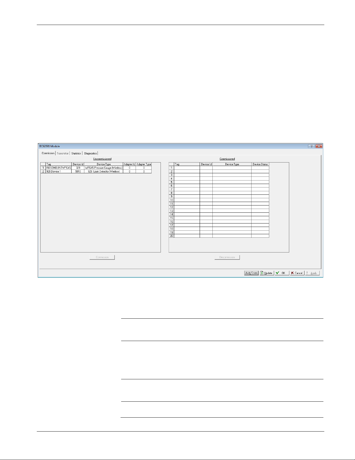
3.2.1 Commissioning Devices
You use the Commission tab to individually or collectively commission
devices.
Figure 3-5. Commission tab
This screen has two lists, Uncommissioned and Commissioned. When
the Status field on the Network screen displays On-line, the 781S
automatically begins adding devices to the Uncommissioned list. To
commission a device, you move it to the Commissioned list in either of
two ways:
Select the device (see Figure 3-5) and click Commission.
ROCLINK 800 places the device in the first available empty row
on the Commissioned list.
Notes:
To select several devices, press Ctrl and left-click each
additional device. Click Commission when you have finished
selecting devices.
When commissioning a HART device connected to an Emerson
Wireless 775 THUM Adapter, the system detects both the
HART device and the THUM Adapter and places them both in
the Uncommissioned list. Commission the device as normal.
Commission the THUM Adapter only if you need the Adapter’s
process data.
Select the device and “drag” it to a position on the Commissioned
list.
3-8 Configuration and Commissioning Revised October 2021
Page 27

IEC 62591 Wireless Interface Instruction Manual (for ROC800-Series and FloBoss 107)
The device does not disappear from the Uncommissioned List until
communication issues have been resolved.
The number of rows on the Commission screen correlates to the number
of wireless devices your controller supports. Each row represents a
specific logical position. If, during commissioning, you want the
controller to store information from a specific wireless device in a
specific logical position, you can commission that device to that logical
by selecting that device and “dragging” it to the appropriate position on
the Commissioned list.
Note: Once you commission a device to a particular logical, you
cannot drag it another logical position. You must first
decommission the device and then re-commission it to the new
logical position.
After a few minutes, the device moves from the Uncommissioned to the
Commissioned list:
Figure 3-6. Commissioned Device
Another indicator that the device has been successfully commissioned is
the activation of the Transmitter tab.
Note: If you change the tag for a transmitter using either a hand-held
375/475 device or the AMS Device Configurator, the new tag
may not display until the device appears on the Commissioned
list.
Decommissioning a Device
If you decide to remove a device from your network, use this screen to
decommission the device. Select the device and drag it to the
Uncommissioned list.
Revised October 2021 Configuration and Commissioning 3-9
Page 28
IEC 62591 Wireless Interface Instruction Manual (for ROC800-Series and FloBoss 107)
Note: Remember to adjust or redefine any TLPs you have designated
to accumulate the information for the decommissioned device’s
logical position.
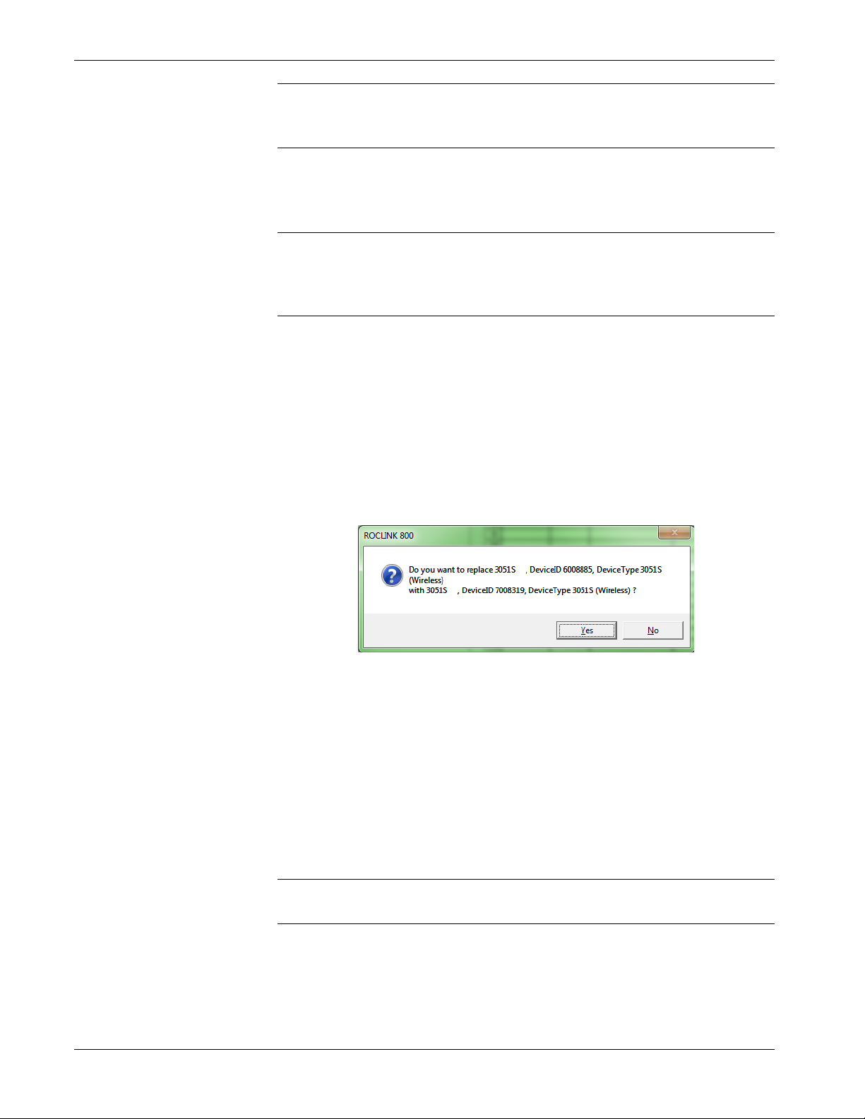
Replacing a Device
If a particular wireless device in your network stops working, you can
easily replace it with a similar device.
Note: Using this option does not require you to adjust or redefine any
TLPs you have designated to accumulate the information for the
decommissioned device’s logical position. The new device
assumes all parameters you have defined for the old device.
First, configure the device for the network, assigning it the appropriate
Network ID and Join Key. Install the device in the field. Start
ROCLINK 800, select the IEC 62591 module, and display the
Commission tab. When the replacement device appears on the
Uncommissioned list, select it and drag it on top of the non-working
device. This tells ROCLINK 800 that you want this new device to
assume all the defined characteristics of the old device.
ROCLINK 800 displays a verification dialog to prevent you from
accidentally replacing a device:
Figure 3-7. Device Replacement Verification Dialog
Click Yes to complete the replacement. ROCLINK commissions the
new device and automatically decommissions the old device, moving it
to the Uncommissioned list.
3.2.2 Managing Device Information
Once you have commissioned a device, the Transmitter tab can provide
you with a variety of information on that device. Select the Transmitter
tab to display the Transmitter screen:
Note: When viewing a transmitter connected to a THUM adaptor, only
the process variables are returned to the IEC62591 module.
3-10 Configuration and Commissioning Revised October 2021
Page 29

IEC 62591 Wireless Interface Instruction Manual (for ROC800-Series and FloBoss 107)
Descriptor
Provides an optional 20-character alphanumeric
Figure 3-8. Transmitter screen
Notes:
You can also double-click a commissioned device on the
Commission screen to immediately access the Transmitter screen for
that device.
If you use ROCLINK to change transmitter values when the
transmitter is busy with other communications tasks, the transmitter
may fail to update and reverts to previous values. If this occurs, you
can use ROCLINK to re-attempt the update when the transmitter is
not busy with other communications tasks. Alternately, avoid this
issue entirely by using a 475 Field Communicator to change
transmitter values.
Field Description
Transmitter
Tag
Message
Displays the 40-character alphanumeric tag
associated with the transmitter. The system adds
the logical position (here, 2 -) to the tag. Click to
display all devices currently defined for this network.
Defines a 40-character alphanumeric identifier for
the transmitter (such as Tank2Level or
Pump1NorthTemporary).
Provides an optional 40-character message
associated with the transmitter. Use this field for
explanatory or warning messages (such as Not to
exceed 300 psi).
Revised October 2021 Configuration and Commissioning 3-11
Configuration
Change Counter
descriptor for the transmitter (such as Casing
press).
This read-only field shows the number of times the
configuration of the transmitter has been changed,
as reported by the transmitter itself.
Page 30

IEC 62591 Wireless Interface Instruction Manual (for ROC800-Series and FloBoss 107)
Field
Description
Transmitter
Information
Comm Status
Device Status
Commission Status
Poll Mode
Process Variables on
Reset
This section displays read-only information
reported by the transmitter, including serial
number, manufacturer ID, type of device, battery
life, and other data.
Note: Battery life is calculated by the transmitter.
Refer to the transmitter’s manufacturer for
further details.
This read-only field shows the status of the
communications channel.
This read-only field shows the Field Device Status
code to indicate the current communication and
operating state of the transmitter. For any value
other than 0, the field turns red.
Note: Hover your mouse over this field to view the
meaning of the response code. Response
codes are manufacturer-defined. Refer to the
documentation provided with the transmitter
or to the manufacturer’s website for a
complete list of response codes, their
meanings, and their resolutions.
This read-only field shows the current status of the
device in the commissioning process. Valid values
are:
0 = Idle (not used)
1 = Configuring Burst Command
2 = Configuring Burst Variables
3 = Configuring Burst Rate
4 = Enabling Bursting
5 = Bursting (field highlighted in green)
6 = Data Stale (field highlighted in yellow)
7 = Communication Failure (field highlighted in red)
8 = Disabling Bursting
Indicates the mode the transmitter uses to acquire
information. The default is Normal, based on the
value in the Burst Rate field. Select Update and
click Apply to immediately perform an on-demand
polling and refresh all fields on this screen. The
mode reverts to Normal at the next Burst Rate
interval.
Sets the process variables to use after a failure.
Valid values are Retain Last Value (use the last
known values for the process variables) or Use
Failsafe Value (use the values entered in the PV
Failsafe, SV Failsafe, TV Failsafe, and QV Failsafe
fields).
3-12 Configuration and Commissioning Revised October 2021
Page 31

IEC 62591 Wireless Interface Instruction Manual (for ROC800-Series and FloBoss 107)
Field
Description
to the FB107.
Process Variables
Enable Fault
Detection
Displays the value, health, and status for the
primary (PV), secondary (SV), tertiary (TV), and
quaternary (QV) dynamic variables. For each
variable, two status fields display to the right of the
Value field.
The upper status field is the Process Data Status,
indicating the overall status of the process variable.
Possible values for this field are Good,
Manual/Fixed, Poor Accuracy, and Bad. The lower
status field is the Limit Status, indicating if the
process variable is responding to changes. Possible
values for this field are Constant, High Limited, Low
Limited, and Not Limited.
The module returns four additional bits, but these
are not displayed through ROCLINK. Bit 3 indicates
the More Device Variable Status Available. Bits 2
through 0 indicate the Device Family Specific
Status. Use TLPs to retrieve these additional bits for
the PV Status (177,x,60), SV Status (177,x,61), TV
Status (177,x,62), and QV Status (177,x,63). For
more information, refer to the Command Summary
Specification (HCF_SPEC-99), available from the
HART Communication Foundation.
Check to enable fault detection on the process
variables. If enabled and the system detects a fault,
the system marks the field in red and displays NaN
(not a number).
Note: You enable fault detection individually for
each process variable. This field applies only
Dynamic Variables
Defines the slot assignment and associated value
for up to four slot-based variables.
Each wireless transmitter contains up to 250 slots
able to store variable information (such as
temperature, pressure, scaling factors, altitude,
flow, and so on). Each transmitter manufacturer
defines which slots contain what information. Refer
to the documentation provided with the transmitter
or to the manufacturer’s website for a complete list
of slot assignments.
Note: WirelessHART conventions require that all
manufacturers reserve slots 246 through
249 for the dynamic variables PV, SV, TV,
and FV, respectively. Slot 250 is also
reserved as permanently unassigned and
does not accumulate values.
Revised October 2021 Configuration and Commissioning 3-13
Page 32

IEC 62591 Wireless Interface Instruction Manual (for ROC800-Series and FloBoss 107)
Field
Description
Discrete Variables
Bursting
Min Update Time
Max Update Time
Trigger Mode
Sets the configuration and shows the status of
connected discrete devices that support discrete
variables. The IEC 62591 module can control a
maximum of four discrete variables that display in a
list in the Discrete Variables field. Refer to the
documentation for your specific discrete device for a
list of available set points and possible statuses.
An example of a discrete device that supports
discrete variables is a discrete valve. You can
configure the set point of the discrete valve as being
Open or Closed. These set points are shown as
radio buttons in the Discrete Variables list. The
status of the device in relation to the configured set
point is displayed in the Discrete Variables list to the
left of the set point. In the discrete valve example,
the status might show Closed, Open, Closing, or
Opening.
Note: Click Update to manually refresh the Status
field.
Displays the Min Update Time, Max Update Time,
Trigger Mode, Trigger Level, Dev Var Classif, Unit
Code and HART Command Execution Status.
Sets the time interval (in seconds) at which the
HART device communicates.
Sets the maximum amount of time (in seconds)
without an update before the HART device
automatically publishes an update.
Sets what conditions cause the HART device to
publish an update at the interval set in the Min
Update time field. Possible options are:
Continuous
Windowed
Rising
Constantly publishes updates at the
Min Update Time.
Publishes updates at the interval set
in the Min Update Time field when the
source deviates from the last
communicated source value by more
than the value set in the Trigger Level
field. If this condition is not met,
updates are published at the interval
set in the Max Update Time field.
Publishes updates at the interval set
in the Min Update Time field when the
source value rises above the value
set in the Trigger Level field. Updates
are published at the Min Update Time
until the value falls below the
threshold. If this condition is not met,
updates are published at the interval
set in the Max Update Time field.
3-14 Configuration and Commissioning Revised October 2021
Page 33

IEC 62591 Wireless Interface Instruction Manual (for ROC800-Series and FloBoss 107)
Field
Description
possible values and their meaning.
Trigger Level
Dev Var Classif
Falling
On-Change
Sets additional data the system needs based on
your selection in the Trigger Mode field.
If you select Windowed in the Trigger Mode field,
sets a deadband value that the source value must
rise above or fall below the last communicated
source value to trigger the change in update
frequency.
If you select Rising in the Trigger Mode field, sets
a value that the source value must rise above to
trigger the change in update frequency.
If you select Falling in the Trigger Mode field, sets
a value that the source value must fall below to
trigger the change in update frequency.
Note: This field displays only if you select
Windowed, Raising, or Falling in the
Trigger Mode field.
This read-only field shows the device variable
classification code that is read at the time of device
discovery.
Note: Refer to HART Communication Foundation
document number HCF Spec 183 for a list of
Publishes updates at the interval set
in the Min Update Time field when the
source value falls below the value set
in the Trigger Level field. Updates are
published at the Min Update Time
until the value rises above the
threshold. If this condition is not met,
updates are published at the interval
set in the Max Update Time field.
Publishes updates at the interval set
in the Min Update Time field when
any value changes. If this condition is
not met, updates are published at the
interval set in the Max Update Time
field.
Unit Code
Revised October 2021 Configuration and Commissioning 3-15
The device engineering unit code that is read at the
time of device discovery.
Note: Refer to HART Communication Foundation
document number HCF_Spec 183 for a list
of possible values and their meaning.
Page 34

IEC 62591 Wireless Interface Instruction Manual (for ROC800-Series and FloBoss 107)
Field
Description
Bit 0
Bit 2
Bit 4
Bit 6
Bit 8
Bit 10
Bit 12
Bit 14
Note:
HART Command
Execution Status
Events
This read-only field shows an indicator when the
IEC 62591 module sends a HART command to the
sensor, and that command is unsuccessful. Each bit
of the indicator represents the following HART
command:
Command 103 Message 0
Bit 1 Command 103 Message 1
Command 104 Message 0
Bit 3 Command 104 Message 1
Command 107 Message 0
Bit 5 Command 107 Message 1
Command 108 Message 0
Bit 7 Command 108 Message 1
Command 109 Message 0
Bit 9 Command 109 Message 1
Command 117
Bit 11 Command 118
Spare
Bit 13 Spare
Spare
Bit 15 Spare
This field shows the status of important
commands for Bursting and Events.
Bursting
o Command 103 Write Burst Period – Writes
Min and Max burst update periods
o Command 104 Write Burst Triggers – Sets
burst trigger mode
o Command 107 Write Burst Device Variables -
Burst device variables returned by device on
command 9 or 33 in burst mode
o Command 108 Write Burst mode command
number
o Command 109 Burst Mode Control – Sets
bursting ON/OFF
Event Notification
o Command 117 Write Event notification timing
– Sets Event notification retry time, Maximum
update time, Event De-bounce interval
o Command 118 Event notification control -
Enable/ Disable event notification
Displays the Publish Time, Max Publish Time,
Debounce Interval, Cur Event Time, Event
Summary, Control Code and Events Pending
3-16 Configuration and Commissioning Revised October 2021
Page 35

IEC 62591 Wireless Interface Instruction Manual (for ROC800-Series and FloBoss 107)
Field
Description
Note:
not
Note:
not
Note: This feature is not currently supported.
read-only
Note:
not
Note:
not
read-only
Note:
not
Note:
not
Min Publish Time
Max Publish Time
Debounce Interval
Cur Event Time
Event Summary
Control Code
Events Pending
Reset Events
Sets the time interval (in seconds) at which the
HART device publishes its events. This value must
be less than or equal to the value you set in the
Maximum Update Time field.
Note: This feature is not currently supported.
Sets the maximum amount of time (in seconds)
without publishing its events before the HART
device is forced to publish its events. This field
applies only if you select Windowed, Raising,
Falling, or On-Change in the Trigger Mode field.
This feature is
This read-only field shows the amount of time (in
seconds) that an event must persist before the
HART device sends a notification.
This feature is
This read-only field shows the time of the current
event as returned from the HART device (the
number of seconds that have passed since the start
of the day) and the system’s interpretation of that
value.
This
pending events.
This feature is
This read-only field shows the Event Notification
Control Code returned from the HART device.
Possible values are:
Off
Token Pass DLL
TDMA DLL
Both TDMA and Token DLLs
This feature is
This
HART device that have not been acknowledged.
Possible values are:
Configuration Changed Event
Device Status Event
More Status Available Event
This feature is
Select this button to acknowledge all pending
events on the HART device.
This feature is
field shows any unacknowledged
field displays a list of events on the
currently supported.
currently supported.
currently supported.
currently supported.
currently supported.
currently supported.
Revised October 2021 Configuration and Commissioning 3-17
Click Apply to save any changes you may make to the values on this
screen.
Page 36
IEC 62591 Wireless Interface Instruction Manual (for ROC800-Series and FloBoss 107)
Field
Description
Bytes Transmitted
read-only
Note: You can also double-click a commissioned device on the
Commission screen to immediately access the Transmitter
screen for that device.
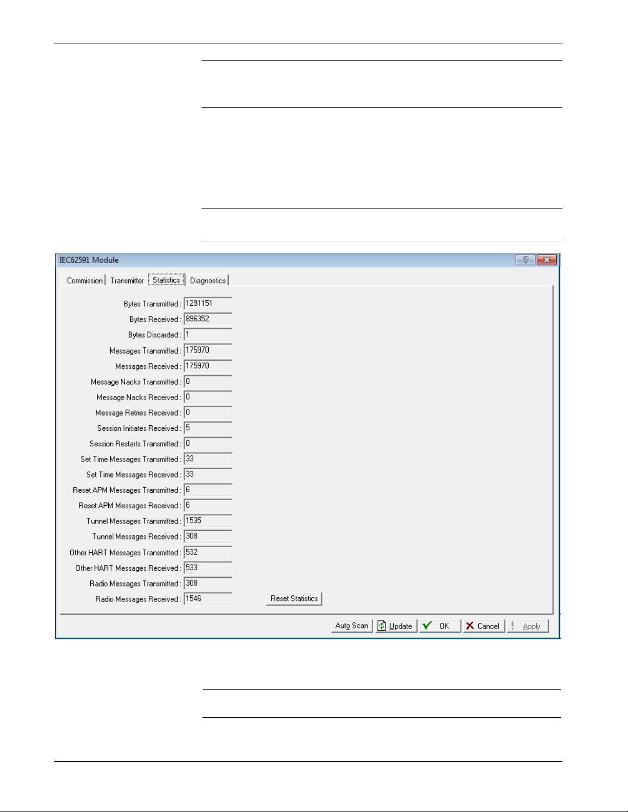
3.2.3 Viewing Network Statistics
The network accumulates a variety of statistical information you can
review to assess system health. This content is returned from the
transmitters and is updated every ten seconds. Select the Statistics tab
to view this information.
Note: Refer to the transmitter's manufacturer for more information
about the fields on this tab.
3-18 Configuration and Commissioning Revised October 2021
Figure 3-9. Statistics screen
This
bytes the IEC62591 module has sent to the 781S.
field shows the number of data
Page 37

IEC 62591 Wireless Interface Instruction Manual (for ROC800-Series and FloBoss 107)
Field
Description
the bus.
781S.
781S.
Received
Bytes Received
Bytes Discarded
Messages
Transmitted
Messages Received
Message Nacks
Transmitted
Message Nacks
Message Retries
Received
Session Initiates
Received
Session Restarts
Transmitted
Set Time Messages
Transmitted
Set Time Messages
Received
This read-only field shows the number of data
bytes the IEC62591 module has received from the
781S.
This read-only field shows the number of bytes
discarded by the IEC62591 module. Discarded
bytes are usually erroneous and due to noise on
This read-only field shows the number of
messages the IEC62591 module has sent to the
This read-only field shows the number of
messages IEC62591 module has received from the
This read-only field shows the number of NACKs
the IEC62591 module has sent to the 781S. A
NACK is typically sent when a received message
contains an error and a re-transmission request is
sent. A high number of NACKs is often an
indication of a poor link connection.
Reserved
This read-only field shows the number of retry
requests the IEC62591 module has received from
the 781S. A retry request is sent by the 781S when
it does not receive an acknowledgement from the
IEC62591 module. A high number of retries is often
an indication of a poor link connection.
This read-only field shows the number of Session
Initiates the IEC62591 module has received from
the 781S. A Session Initiate is sent by the 781S
when it wants to start and/or restart
communications with the IEC62591 module (for
example, after the 781S (first powers up).
This read-only field shows the number of Session
Restart requests the IEC62591 module has sent to
the 781S. A Session Restart request is sent by the
IEC62591 module to request a bus restart of the
communications with the 781S (for example, after
the IEC62591 module first powers up).
This read-only field shows the number of Set Time
messages the IEC62591 module has sent to the
781S. A Set Time message is part of the time
management process used to keep the
WirelessHART network time up to date.
This read-only field shows the number of Set Time
messages the IEC62591 module has received from
the 781S.
Revised October 2021 Configuration and Commissioning 3-19
Page 38

IEC 62591 Wireless Interface Instruction Manual (for ROC800-Series and FloBoss 107)
Field
Description
Reset APM Messages
This read-only field shows the number of Reset
Reset Statistics
Click to reset all values on this tab.
Reset APM Messages
Transmitted
Received
Tunnel Messages
Transmitted
Tunnel Messages
Received
Other HART
Messages
Transmitted
Other HART
Messages Received
Radio Messages
Transmitted
Radio Messages
Received
This read-only field shows the number of Reset
APM messages the IEC62591 module has sent to
the 781S. A Reset APM message is part of the
wireless management process used to restart the
WirelessHART radio on the 781S.
APM messages the IEC62591 module has received
from the 781S.
This read-only field shows the number of Tunnel
messages the IEC62591 module has sent to the
781S. A Tunnel message is part of the wireless
management process used to send information
across the WirelessHART network.
This read-only field shows the number of Tunnel
messages the IEC62591 module has received from
the 781S.
This read-only field shows the number of 781S-
specific messages the IEC62591 module has sent
to the 781S. These messages are sent to retrieve
data from the 781S.
This read-only field shows the number of 781S-
specific messages the IEC62591 module has
received from the 781S.
This read-only field shows the number of
WirelessHART network messages the IEC62591
module has sent to the 781S.
This read-only field shows the number of
WirelessHART network messages the IEC62591
module has received from the 781S.
3.2.4 Retrieving a Diagnostic Log
The IEC 62591 module has a USB port which you can use to retrieve a
diagnostic log to assist in troubleshooting. Select the Diagnostics tab to
display the Diagnostics screen:
Note: It may take up to three minutes after initial installation or after
3-20 Configuration and Commissioning Revised October 2021
updating module firmware before the IEC 62591 module
recognizes a drive plugged into the module's USB port.
Page 39

IEC 62591 Wireless Interface Instruction Manual (for ROC800-Series and FloBoss 107)
Field
Description
Figure 3-10. Diagnostics screen
The screen provides basic information to create and process the
diagnostic log. However, Technical Support personnel can use the
Logging Severity frame to more thoroughly identify problems in your
system.
Set Logging Level
Click to set the severity of logs. The system
validates your selection by displaying the message
Set Logging Severity X COMPLETED, where X
represents the severity you have selected.
3.2.5 Displaying Commissioned Transmitters
From the main IEC 62591 module screen, you can display and quickly
access transmitter-specific information. Select the Transmitter tab to
display the Transmitter screen.
Revised October 2021 Configuration and Commissioning 3-21
Page 40

IEC 62591 Wireless Interface Instruction Manual (for ROC800-Series and FloBoss 107)
Figure 3-11. Transmitter screen
This screen shows the logical point to which you have installed the
device, the device’s 23-character alphanumeric (long) tag, and any
integrity issues for that device (as shown for the device assigned to
point 2). Double-click a device to display the Transmitter screen (see
Figure 3-7) for that device.
3.3 IEC 62591 Module Interface (ROC800)
To access the screens you use to configure and commission the network:
Start ROCLINK 800 and click the IEC62591 Module on the graphical
interface. The IEC62591 Module screen displays:
3-22 Configuration and Commissioning Revised October 2021
Page 41

IEC 62591 Wireless Interface Instruction Manual (for ROC800-Series and FloBoss 107)
Tab
Description
Network
Defines the Join Key and Network ID for the
Statistics
Figure 3-12. IEC 62591Module
The module has six tabs:
Module
Commission
Transmitter
Statistics
Provides read-only statistical information about the
IEC 62591 module, such as serial number and part
numbers.
network. These values must correspond to the
Network ID and Join Key in the devices.
Auto-detects available uncommissioned devices
and enables you to add them to the defined
network.
Accesses both read-only statistics and modifiable
parameters for a specific device associated with the
network.
Provides read-only statistics the 781S has
accumulated for the network. Click Reset
to reset these values at any time.
Revised October 2021 Configuration and Commissioning 3-23
Page 42
IEC 62591 Wireless Interface Instruction Manual (for ROC800-Series and FloBoss 107)
Tab
Description
Diagnostics
The following sections discuss how to use these tabs to manage your
network.
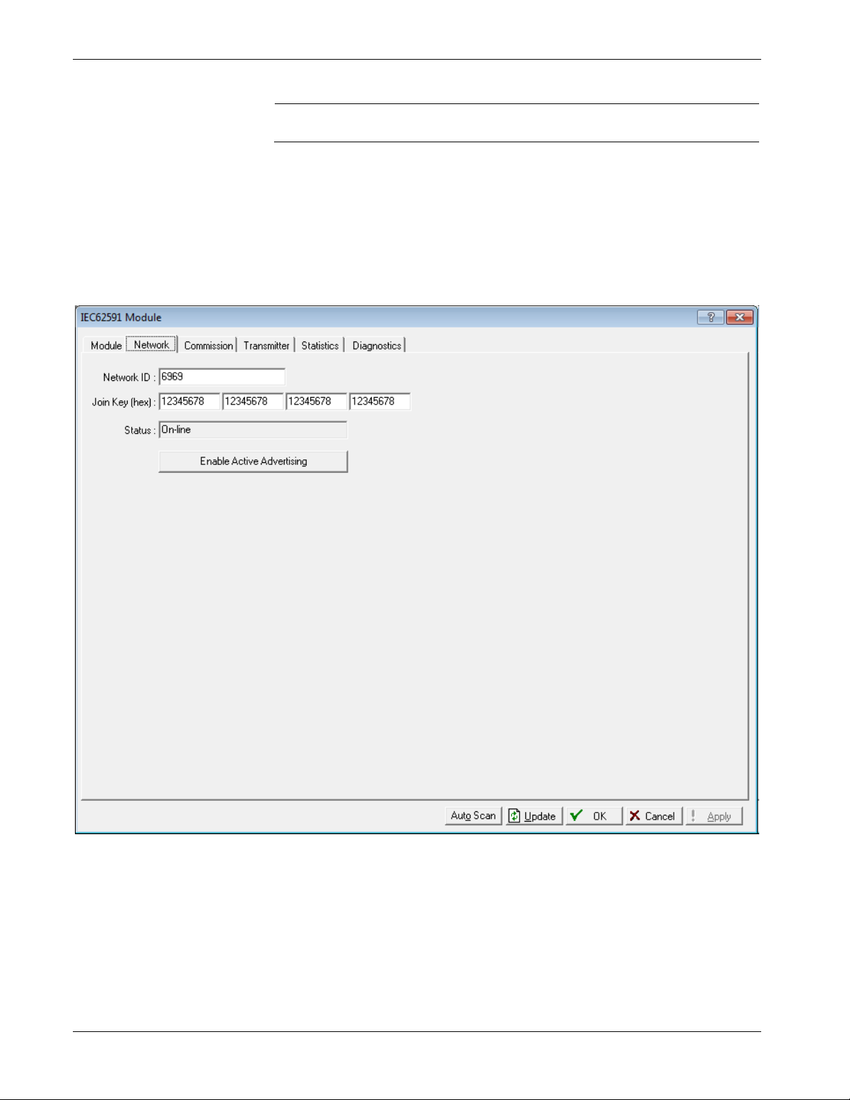
3.3.1 Accessing the Network
Use this screen to identify the Network ID and Join Key for the devices
in your network. When you select the Network tab, you must complete
two fields:
Describes how to use the module’s USB port to
generate log information for resolving issues.
Figure 3-13. Network tab
3-24 Configuration and Commissioning Revised October 2021
Page 43

IEC 62591 Wireless Interface Instruction Manual (for ROC800-Series and FloBoss 107)
Field
Description
Enter a five-character Network ID. Valid values are
00000).
three
Network ID
Join Key (hex)
Status
Enable Active
Advertising
1 to 36863.
Should be noted that each IEC62591 Module / RTU
can only have a single Network ID. The "grouping"
should be related to the control/monitoring network
for a given RTU. For example, if two RTUs are
installed at a site, each grouping should be the set
of meter runs each RTU controls.
Note: A Network ID cannot be all zeros (such as
Enter a valid Join Key to permit the device to
access its defined network.
A Join Key is a 128-byte value expressed as four
32-bit portions. As shown in the example, you can
use zeros for the first
This read-only field shows the current status of the
connection between the network and ROCLINK
800.
Click to enable active advertising, in which the IEC
62591 module continuously broadcasts network
information. This enables new devices to quickly
join the network. Active advertising broadcasts
network information continuously for approximately
30 minutes.
Additionally, active advertising occurs automatically
when:
You first power up or restart the IEC 62591
module or
A device leaves the network (which allows
communications to re-establish).
parts of the Join Key.
Click Apply. As the 781S processes your request to add the device to
the network, the value displayed in the Status field changes:
Initializing. The module is in the boot-up sequence. The module
Configuring Network. The code is running and the module is
Detecting radio. The 781S recognizes the network.
Revised October 2021 Configuration and Commissioning 3-25
sends info (Part Number, firmware version, etc.) to the RTU. During
this time, the module is not yet communicating with the RTU. Once
the code starts up (usually after 30-60 seconds), the module switches
from Initializing to Configuring Network.
attempting to pull configuration info from the RTU. If the
Initializing status is taking too long, it means that either
the board is not completely booting up, or
the application code is not correctly loading. As a result, the
sequence cannot complete.
Page 44
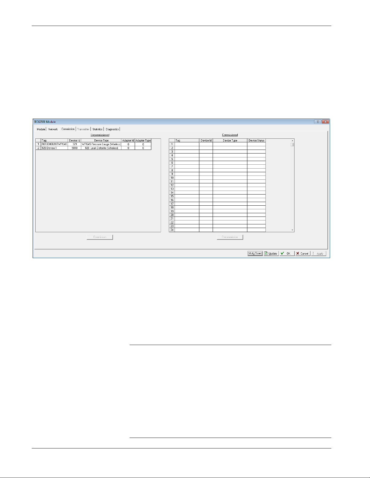
IEC 62591 Wireless Interface Instruction Manual (for ROC800-Series and FloBoss 107)
On-Line. When the Status field shows On-line, you can begin
commissioning devices for the network.
Proceed to Commissioning Devices.
3.3.2 Commissioning Devices
When you select the Commission tab, ROCLINK 800 displays the
Commission screen (see Figure 3-16). You use this screen to
individually or collectively commission devices.
Figure 3-14. Commission tab
This screen has two lists, Uncommissioned and Commissioned. When
the Status field on the Network screen displays On-line, ROCLINK 800
automatically begins adding devices to the Uncommissioned list. To
commission a device, you move it to the Commissioned list in either of
two ways:
Select the device and click Commission. ROCLINK 800 places the
device in the first available empty position.
Notes:
To select several devices, press Ctrl and left-click each
additional device. Click Commission when you have finished
selecting devices.
When commissioning a HART device connected to an Emerson
Wireless 775 THUM Adapter, the system detects both the
HART device and the THUM Adapter and places them both in
the Uncommissioned list. Commission the device as normal.
Commission the THUM Adapter only if you need the Adapter’s
process data.
3-26 Configuration and Commissioning Revised October 2021
Page 45
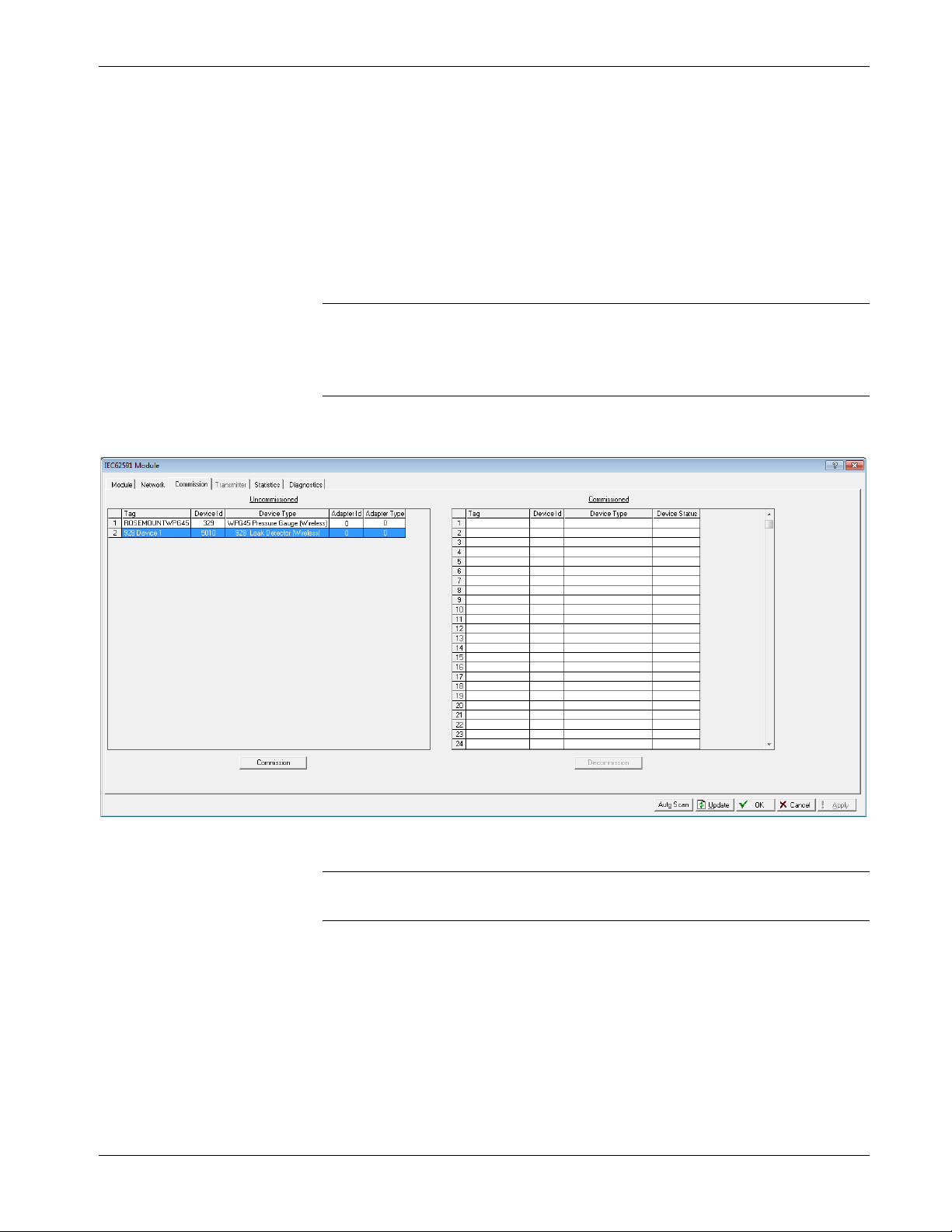
IEC 62591 Wireless Interface Instruction Manual (for ROC800-Series and FloBoss 107)
Select the device and “drag” it to a position on the Commissioned
list.
The number of rows on the Commission screen correlates to the number
of wireless devices your controller supports. Each row represents a
specific logical position. If, during commissioning, you want the
controller to store information from a specific wireless device in a
specific logical position, you can commission that device to that logical
by selecting that device and “dragging” it to the appropriate position on
the Commissioned list.
Note: Once you commission a device to a particular logical, you
cannot drag it another logical position. You must first
decommission the device and then recommission it to the new
logical position.
When you select a device in the Uncommissioned column, the
Commission button activates:
Figure 3-15. Active Commission button
Note: To select more than one device, press the Ctrl key and left-click
each additional device.
Click Commission. After a few minutes, the device moves from the
Uncommissioned to the Commissioned list:
Revised October 2021 Configuration and Commissioning 3-27
Page 46
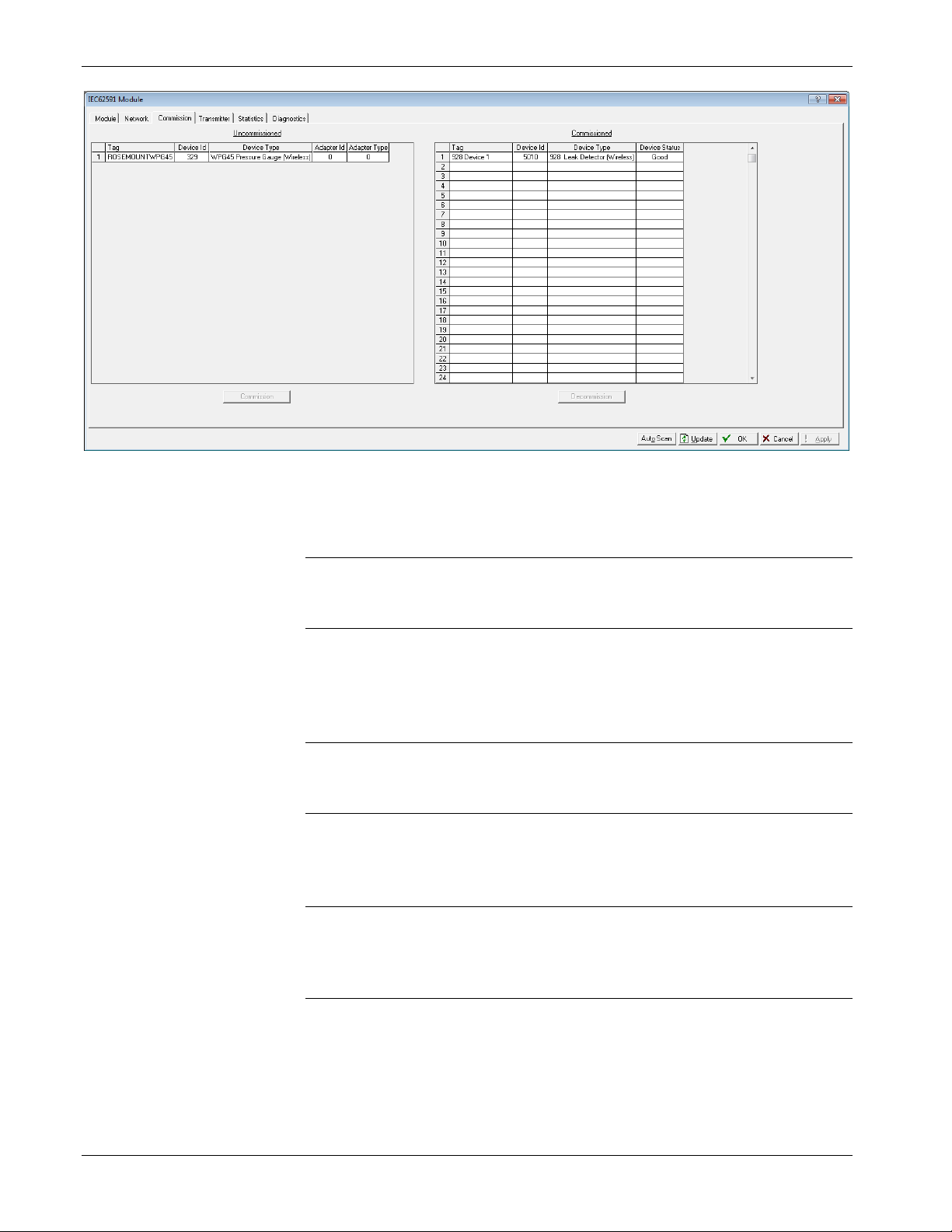
IEC 62591 Wireless Interface Instruction Manual (for ROC800-Series and FloBoss 107)
Figure 3-16. Commissioned Device
Another indicator that the device has been successfully commissioned is
the activation of the Transmitter tab.
Note: If you change the tag for a transmitter using either a hand-held
375/475 device or AMS Device Configurator, the new tag may
not display until the device appears on the Commissioned list.
Decommissioning a Device
If you decide to remove a device from your network, use this screen to
decommission the device. Select the device and drag it to the
Uncommissioned list.
Note: Remember to adjust or redefine any TLPs you have designated
to accumulate the information for the decommissioned device’s
logical position.
Replacing a Device
If a particular wireless device in your network stops working, you can
easily replace it with a similar device.
Note: Using this option does not require you to adjust or redefine any
TLPs you have designated to accumulate the information for the
decommissioned device’s logical position. The new device
assumes all parameters you have defined for the old device.
First, configure the device for the network, assigning it the appropriate
Network ID and Join Key. Install the device in the field. Start
ROCLINK 800, select the IEC 62591 module, and display the
Commission tab. When the replacement device appears on the
Uncommissioned list, select it and drag it on top of the non-working
3-28 Configuration and Commissioning Revised October 2021
Page 47
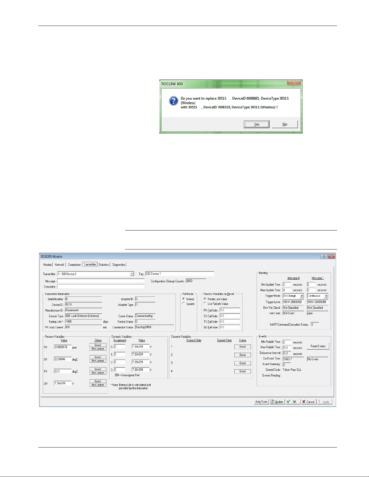
IEC 62591 Wireless Interface Instruction Manual (for ROC800-Series and FloBoss 107)
device. This tells ROCLINK 800 that you want this new device to
assume all the defined characteristics of the old device.
ROCLINK 800 displays a verification dialog to prevent you from
accidentally replacing a device:
Figure 3-17. Device Replacement Verification Dialog
Click Yes to complete the replacement. ROCLINK commissions the
new device and automatically decommissions the old device, moving it
to the Uncommissioned list.
3.3.3 Managing Device Information
Once you have commissioned a device, the Transmitter tab can provide
you with a variety of information on that device. Selecting the
Transmitter tab displays the Transmitter screen:
Note: When viewing a transmitter connected to a THUM adaptor, only
the process variables are returned to the IEC62591 module.
Figure 3-18. Transmitter tab
Revised October 2021 Configuration and Commissioning 3-29
Page 48

IEC 62591 Wireless Interface Instruction Manual (for ROC800-Series and FloBoss 107)
Field
Description
network.
Transmitter
read-onl
communications channel.
Device Status
Notes:
You can also double-click a commissioned device on the
Commission screen to immediately access the Transmitter screen for
that device.
If you use ROCLINK to change transmitter values when the
transmitter is busy with other communications tasks, the transmitter
may fail to update and reverts to previous values. If this occurs, you
can use ROCLINK to re-attempt the update when the transmitter is
not busy with other communications tasks. Alternately, avoid this
issue entirely by using a 475 Field Communicator to change
transmitter values.
Transmitter
Tag
Message
Descriptor
Configuration
Change Counter
Information
Comm Status
Displays the 40-character alphanumeric tag
associated with the transmitter. The system adds
the logical position (here, 1 - ) to the tag. Click
to display all devices currently defined for this
Defines a 40-character alphanumeric identifier for
the transmitter (such as Tank2Level or
Pump1Temporary).
Provides an optional 40-character alphanumeric
message associated with the transmitter. Use this
field for explanatory or warning messages (such
as Not to exceed 300 psi).
Provides an optional 20-character alphanumeric
description of transmitter (such as Casing press).
This read-only field shows the number of times
the configuration of the transmitter has been
changed, as reported by the transmitter itself.
This section displays
reported by the transmitter, including serial
number, manufacturer ID, type of device, battery
life, and other data.
Note: Battery life is calculated by the transmitter.
Refer to the transmitter’s manufacturer for
further details.
This read-only field shows the status of the
y information
3-30 Configuration and Commissioning Revised October 2021
This read-only field shows the Field Device Status
code to indicate the current communication and
operating state of the transmitter. For any value
other than 0, the field turns red.
Note: Hover your mouse over this field to view
the meaning of the response code.
Response codes are manufacturer-defined.
Refer to the documentation provided with
the transmitter or to the manufacturer’s
website for a complete list of response
codes, their meanings, and their
resolutions.
Page 49

IEC 62591 Wireless Interface Instruction Manual (for ROC800-Series and FloBoss 107)
Field
Description
Process Variables on
Adapter ID
Adapter Type
Commission Status
Poll Mode
Reset
Process Variables
Dynamic Variables
Indicates the THUM adapter ID, attached to the
device.
Indicates the THUM adapter type, attached to the
device.
Indicates the current status of the device in the
commissioning process. Valid values are:
0 = Logical Not Used (Idle)
1 = Configuring Burst Command
2 = Configuring Burst Variables
3 = Configuring Burst Rate
4 = Enabling Bursting
5 = Bursting (field highlighted in green)
6 = Data Stale (field highlighted in yellow)
7 = Communication Failure (field highlighted in
red)
8 = Disabling Bursting
9 = Delayed Response
10 = Commissioning Failed
Indicates the mode the transmitter uses to acquire
information. The default is Normal, based on the
value in the Burst Rate field. Select Update and
click Apply to immediately perform an on-demand
polling and refresh all fields on this screen. The
mode reverts to Normal at the next Burst Rate
interval.
Sets the process variables to use after a failure.
Valid values are Retain Last Value (use the last
known values for the process variables) or Use
Failsafe Value (use the values entered in the PV
Failsafe, SV Failsafe, TV Failsafe, and QV Failsafe
fields).
Displays the values for the primary (PV),
secondary (SV), tertiary (TV), and quaternary (QV)
process variables.
Defines the slot assignment and associated value
for up to four slot-based variables.
Each wireless transmitter contains up to 250 slots
able to store variable information (such as
temperature, pressure, scaling factors, altitude,
flow, and so on). Each transmitter manufacturer
defines which slots contain what information. Refer
to the documentation provided with the transmitter
or to the manufacturer’s website for a complete list
of slot assignments.
Note: WirelessHART conventions require that all
manufacturers reserve slots 246 through
249 for the dynamic variables PV, SV, TV,
and FV, respectively. Slot 250 is also
reserved as permanently unassigned and
does not accumulate values.
Revised October 2021 Configuration and Commissioning 3-31
Page 50

IEC 62591 Wireless Interface Instruction Manual (for ROC800-Series and FloBoss 107)
Field
Description
Code and HART Command Execution Status.
Max Update Time
automatically publishes an update.
Min Update Time.
set in the Max Update Time field.
Discrete Variables
Process Variables
Dynamic Variables
Sets the configuration and shows the status of
connected discrete devices that support discrete
variables. The IEC 62591 module can control a
maximum of four discrete variables that display in
a list in the Discrete Variables field. Refer to the
documentation for your specific discrete device for
a list of available set points and possible statuses.
An example of a discrete device that supports
discrete variables is a discrete valve. You can
configure the set point of the discrete valve as
being Open or Closed. These set points are shown
as radio buttons in the Discrete Variables list. The
status of the device in relation to the configured
set point is displayed in the Discrete Variables list
to the left of the set point. In the discrete valve
example, the status might show Closed, Open,
Closing, or Opening.
Note: Click Update to manually refresh the Status
field.
Displays the Min Update Time, Max Update Time,
Trigger Mode, Trigger Level, Dev Var Classif, Unit
Sets the time interval (in seconds) at which the
HART device communicates.
Sets the maximum amount of time (in seconds)
without an update before the HART device
Trigger Mode
Sets what conditions cause the HART device to
publish an update at the interval set in the Min
Update time field. Possible options are:
Continuous
Windowed
Rising
Constantly publishes updates at the
Publishes updates at the interval set
in the Min Update Time field when the
source deviates from the last
communicated source value by more
than the value set in the Trigger Level
field. If this condition is not met,
updates are published at the interval
set in the Max Update Time field.
Publishes updates at the interval set
in the Min Update Time field when the
source value rises above the value
set in the Trigger Level field. Updates
are published at the Min Update Time
until the value falls below the
threshold. If this condition is not met,
updates are published at the interval
3-32 Configuration and Commissioning Revised October 2021
Page 51

IEC 62591 Wireless Interface Instruction Manual (for ROC800-Series and FloBoss 107)
Field
Description
Trigger Level
Dev Var Classif
Unit Code
Falling
On-Change
Sets additional data the system needs based on
your selection in the Trigger Mode field.
If you select Windowed in the Trigger Mode field,
sets a deadband value that the source value must
rise above or fall below the last communicated
source value to trigger the change in update
frequency.
If you select Rising in the Trigger Mode field, sets
a value that the source value must rise above to
trigger the change in update frequency.
If you select Falling in the Trigger Mode field, sets
a value that the source value must fall below to
trigger the change in update frequency.
Note: This field displays only if you select
Windowed, Raising, or Falling in the
Trigger Mode field.
This read-only field shows the device variable
classification code that is read at the time of device
discovery.
Note: Refer to HART Communication Foundation
document number HCF Spec 183 for a list of
possible values and their meaning.
The device engineering unit code that is read at the
time of device discovery.
Note: Refer to HART Communication Foundation
document number HCF_Spec 183 for a list
of possible values and their meaning.
Publishes updates at the interval set
in the Min Update Time field when the
source value falls below the value set
in the Trigger Level field. Updates are
published at the Min Update Time
until the value rises above the
threshold. If this condition is not met,
updates are published at the interval
set in the Max Update Time field.
Publishes updates at the interval set
in the Min Update Time field when
any value changes. If this condition is
not met, updates are published at the
interval set in the Max Update Time
field.
Revised October 2021 Configuration and Commissioning 3-33
Page 52

Field
Description
HART Command
Bit 0
Bit 2
Bit 4
Bit 6
Bit 8
Bit 10
Bit 12
Bit 14
Note:
IEC 62591 Wireless Interface Instruction Manual (for ROC800-Series and FloBoss 107)
This read-only field shows an indicator when the
Execution Status
Events
IEC 62591 module sends a HART command to the
sensor, and that command is unsuccessful. Each bit
of the indicator represents the following HART
command:
Command 103 Message 0
Bit 1 Command 103 Message 1
Command 104 Message 0
Bit 3 Command 104 Message 1
Command 107 Message 0
Bit 5 Command 107 Message 1
Command 108 Message 0
Bit 7 Command 108 Message 1
Command 109 Message 0
Bit 9 Command 109 Message 1
Command 117
Bit 11 Command 118
Spare
Bit 13 Spare
Spare
Bit 15 Spare
This field shows the status of important
commands for Bursting and Events.
Bursting
o Command 103 Write Burst Period – Writes
Min and Max burst update periods
o Command 104 Write Burst Triggers – Sets
burst trigger mode
o Command 107 Write Burst Device Variables
- Burst device variables returned by device
on command 9 or 33 in burst mode
o Command 108 Write Burst mode command
number
o Command 109 Burst Mode Control – Sets
bursting ON/OFF
Event Notification
o Command 117 Write Event notification timing
– Sets Event notification retry time, Maximum
update time, Event De-bounce interval
o Command 118 Event notification control -
Enable/ Disable event notification
Displays the Publish Time, Max Publish Time,
Debounce Interval, Cur Event Time, Event
Summary, Control Code and Events Pending
3-34 Configuration and Commissioning Revised October 2021
Page 53

IEC 62591 Wireless Interface Instruction Manual (for ROC800-Series and FloBoss 107)
Field
Description
Note:
not
Note:
not
Note:
not
Note: This feature is not currently supported.
read-only
Note:
not
Note: This feature is not currently supported.
read-only
Note:
not
Note:
not
Min Publish Time
Max Publish Time
Debounce Interval
Cur Event Time
Sets the time interval (in seconds) at which the
HART device publishes its events.
Note: This value must be less than or equal to the
value you set in the Maximum Update Time
field.
This feature is
Sets the maximum amount of time (in seconds)
without publishing its events before the HART
device is forced to publish its events.
Note: This field applies only if you select
Windowed, Raising, Falling, or OnChange in the Trigger Mode field.
This feature is
This read-only field shows the amount of time (in
seconds) that an event must persist before the
HART device sends a notification.
This feature is
This read-only field shows the time of the current
event as returned from the HART device (the
number of seconds that have passed since the start
of the day) and the system’s interpretation of that
value.
currently supported.
currently supported.
currently supported.
Event Summary
Control Code
Events Pending
Reset Events
This
pending events.
This feature is
This read-only field shows the Event Notification
Control Code returned from the HART device.
Possible values are:
Off
Token Pass DLL
TDMA DLL
Both TDMA and Token DLLs
This
HART device that have not been acknowledged.
Possible values are:
Configuration Changed Event
Device Status Event
More Status Available Event
This feature is
Select this button to acknowledge all pending
events on the HART device.
This feature is
field shows any unacknowledged
currently supported.
field displays a list of events on the
currently supported.
currently supported.
Revised October 2021 Configuration and Commissioning 3-35
Click Apply to save any changes you may make to the values on this
screen.
Page 54
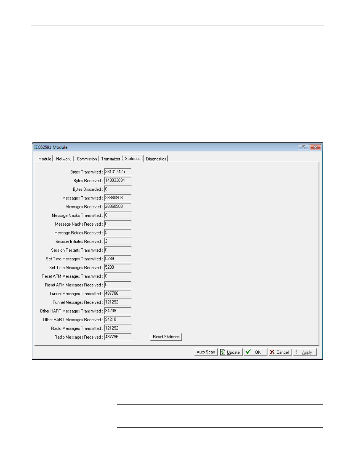
IEC 62591 Wireless Interface Instruction Manual (for ROC800-Series and FloBoss 107)
Field
Description
Bytes Received
read-only
Note: You can also double-click a commissioned device on the
Commission screen to immediately access the Transmitter
screen for that device.
3.3.4 Viewing Network Statistics
The network accumulates a variety of statistical information you can
review to assess system health. This content is returned from the
transmitters and is updated every ten seconds. Select the Statistics tab
to view this information.
Note: Refer to the transmitter's manufacturer for more information
about the fields on this tab.
3-36 Configuration and Commissioning Revised October 2021
Figure 3-19. Statistics tab
Bytes Transmitted
This read-only field shows the number of data
bytes the IEC62591 module has sent to the 781S.
This
bytes the IEC62591 module has received from the
781S.
field shows the number of data
Page 55

IEC 62591 Wireless Interface Instruction Manual (for ROC800-Series and FloBoss 107)
Field
Description
781S.
781S.
Received
Bytes Discarded
Messages
Transmitted
Messages Received
Message Nacks
Transmitted
Message Nacks
Message Retries
Received
Session Initiates
Received
Session Restarts
Transmitted
Set Time Messages
Transmitted
Set Time Messages
Received
Reset APM Messages
Transmitted
Reset APM Messages
Received
This read-only field shows the number of bytes
discarded by the IEC62591 module. Discarded
bytes are usually erroneous and due to noise on
the bus.
This read-only field shows the number of
messages the IEC62591 module has sent to the
This read-only field shows the number of
messages IEC62591 module has received from the
This read-only field shows the number of NACKs
the IEC62591 module has sent to the 781S. A
NACK is typically sent when a received message
contains an error and a retransmission request is
sent. A high number of NACKs is often an
indication of a poor link connection.
Reserved
This read-only field shows the number of retry
requests the IEC62591 module has received from
the 781S. A retry request is sent by the 781S when
it does not receive an acknowledgement from the
IEC62591 module. A high number of retries is often
an indication of a poor link connection.
This read-only field shows the number of Session
Initiates the IEC62591 module has received from
the 781S. A Session Initiate is sent by the 781S
when it wants to start and/or restart
communications with the IEC62591 module (for
example, after the 781S (first powers up).
This read-only field shows the number of Session
Restart requests the IEC62591 module has sent to
the 781S. A Session Restart request is sent by the
IEC62591 module to request a bus restart of the
communications with the 781S (for example, after
the IEC62591 module first powers up).
This read-only field shows the number of Set Time
messages the IEC62591 module has sent to the
781S. A Set Time message is part of the time
management process used to keep the
WirelessHART network time up to date.
This read-only field shows the number of Set Time
messages the IEC62591 module has received from
the 781S.
This read-only field shows the number of Reset
APM messages the IEC62591 module has sent to
the 781S. A Reset APM message is part of the
wireless management process used to restart the
WirelessHART radio on the 781S.
This read-only field shows the number of Reset
APM messages the IEC62591 module has received
from the 781S.
Revised October 2021 Configuration and Commissioning 3-37
Page 56

IEC 62591 Wireless Interface Instruction Manual (for ROC800-Series and FloBoss 107)
Field
Description
Tunnel Messages
This read-only field shows the number of Tunnel
data from the 781S.
received from the 781S.
module has sent to the 781S.
module has received from the 781S.
Reset Statistics
Click to reset all values on this tab.
Tunnel Messages
Transmitted
Received
Other HART
Messages
Transmitted
Other HART
Messages Received
Radio Messages
Transmitted
Radio Messages
Received
This read-only field shows the number of Tunnel
messages the IEC62591 module has sent to the
781S. A Tunnel message is part of the wireless
management process used to send information
across the WirelessHART network.
messages the IEC62591 module has received from
the 781S.
This read-only field shows the number of 781S
specific messages the IEC62591 module has sent
to the 781S. These messages are sent to retrieve
This read-only field shows the number of 781S
specific messages the IEC62591 module has
This read-only field shows the number of
WirelessHART network messages the IEC62591
This read-only field shows the number of
WirelessHART network messages the IEC62591
3.3.5 Retrieving a Diagnostic Log
The IEC 62591 module has a USB port which you can use to retrieve a
diagnostic log to assist in troubleshooting. Select the Diagnostics table
to display the Diagnostics screen:
3-38 Configuration and Commissioning Revised October 2021
Page 57

IEC 62591 Wireless Interface Instruction Manual (for ROC800-Series and FloBoss 107)
Field
Description
Figure 3-20. Diagnostics tab
The screen provides basic information to create and process the
diagnostic log. However, Technical Support personnel can use the
Logging Severity frame to more thoroughly identify problems with your
system.
Logging Severity
Set Logging Level
3.4 Updating Module Firmware
You can also use the USB port on the IEC 62591 module to upgrade the
firmware on the module.
Sets the amount of accumulated system activity
data included on the diagnostic log. 1 is the least
comprehensive setting and 9 is the most
comprehensive setting. The default setting is 7.
Note: Use this field only under the direction of
Technical Support personnel.
Click to set the severity of logs. The system
validates your selection by displaying the message
Set Logging Severity X COMPLETED, where X
represents the severity you have selected.
Caution
Revised October 2021 Configuration and Commissioning 3-39
Do not use the USB port unless the area is known to be non-hazardous.
Page 58

IEC 62591 Wireless Interface Instruction Manual (for ROC800-Series and FloBoss 107)
To access this option, select Utilities > Update Firmware on the
ROCLINK 800 main menu bar. The Update Firmware screen displays.
Figure 3-21. Update Firmware tab
Select the IEC62591 Module tab. The IEC 62591 Module screen
displays:
3-40 Configuration and Commissioning Revised October 2021
Page 59

IEC 62591 Wireless Interface Instruction Manual (for ROC800-Series and FloBoss 107)
Figure 3-22. IEC 62591 Module Firmware Update screen
Follow the procedures on this screen to update the firmware in the IEC
62591 module.
Note: The value in the Current Version field changes when the
firmware update completes.
3.4.1 Updating the IEC 62591 Module Firmware (ROC800/ FloBoss 107)
Follow the procedures on this screen to update the firmware in the IEC
62591 module.
Attach a USB drive (with at least 40Mb of free space) to the PC.
Revised October 2021 Configuration and Commissioning 3-41
Page 60
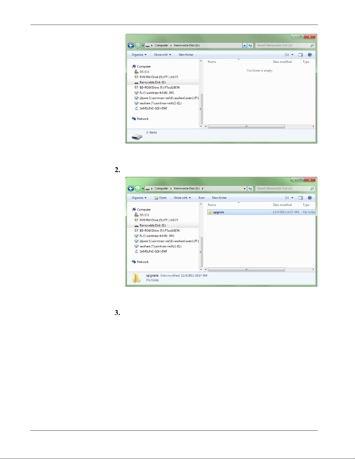
IEC 62591 Wireless Interface Instruction Manual (for ROC800-Series and FloBoss 107)
Figure 3-23. Attaching a USB drive
Create a folder named upgrade in the root directory.
Figure 3-24. Creating the Upgrade Folder
Copy the upgrade file (here, ras-wihart-1.10-release.zip) to the
Upgrade folder on the USB drive.
3-42 Configuration and Commissioning Revised October 2021
Page 61
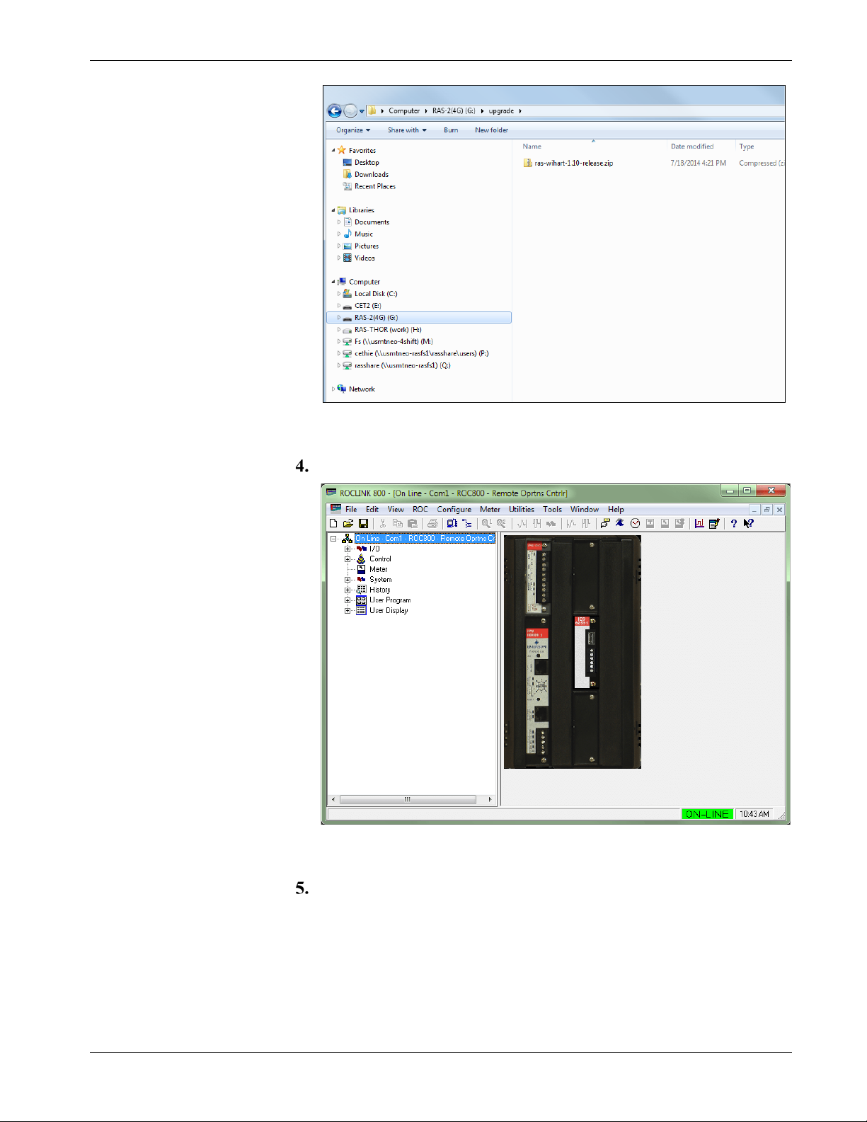
IEC 62591 Wireless Interface Instruction Manual (for ROC800-Series and FloBoss 107)
Figure 3-25. Copying the Upgrade File
Start ROCLINK.
Figure 3-26. Starting ROCLINK
Click on the IEC62591 Module to verify that it is running. The
System Mode field should display Run Mode.
Revised October 2021 Configuration and Commissioning 3-43
Page 62

IEC 62591 Wireless Interface Instruction Manual (for ROC800-Series and FloBoss 107)
Figure 3-27. Verifying Run Mode
Verify that the module is connected to the network and that the
module is currently on-line.
Figure 3-28. Verifying Online Status
Remove the USB drive for your PC’s USB port and attach it to the
USB port on the IEC 62591 module.
On the main ROCLINK screen select Utilities > Update Firmware.
3-44 Configuration and Commissioning Revised October 2021
Page 63

IEC 62591 Wireless Interface Instruction Manual (for ROC800-Series and FloBoss 107)
Figure 3-29. Selecting Utilities > Update Firmware
Select the IEC62591 Module tab and verify that the Current
Version. Click Start to begin the update process.
Figure 3-30. Verifying Current Version
When the dialog displays, click Yes to start the update process.
Revised October 2021 Configuration and Commissioning 3-45
Page 64

IEC 62591 Wireless Interface Instruction Manual (for ROC800-Series and FloBoss 107)
Figure 3-31. Starting the Firmware Update Process
ROCLINK begins the firmware update and displays status messages
at the bottom of the screen.
Figure 3-32. Status message: Waiting for upgrade to start
Once the update starts, it takes several minutes to complete. Status
messages continue to display at the bottom of the screen.
3-46 Configuration and Commissioning Revised October 2021
Page 65

IEC 62591 Wireless Interface Instruction Manual (for ROC800-Series and FloBoss 107)
Figure 3-33. Status message: Upgrade in Progress
When the update completes, the program reboots the module.
Figure 3-34. Status message: Waiting for module to reboot
When the firmware update finishes, a dialog displays. Click OK to
continue.
Revised October 2021 Configuration and Commissioning 3-47
Page 66

IEC 62591 Wireless Interface Instruction Manual (for ROC800-Series and FloBoss 107)
Figure 3-35. Firmware Update Completed Dialog
Verify that the version of firmware for the module is now updated.
Figure 3-36. Verifying Version of Upgraded Firmware
The update process preserves the network settings for your module,
but you should still verify that the settings are correct. Click Cancel
to close the Update Firmware screen, click on the IEC62591
Module tab, and select the Network tab to review the network
settings.
3-48 Configuration and Commissioning Revised October 2021
Page 67

IEC 62591 Wireless Interface Instruction Manual (for ROC800-Series and FloBoss 107)
Figure 3-37. Verifying the Correct Settings
The update is complete. Remove the USB drive from the port on the
IEC 62591 module.
Revised October 2021 Configuration and Commissioning 3-49
Page 68

IEC 62591 Wireless Interface Instruction Manual (for ROC800-Series and FloBoss 107)
3-50 Configuration and Commissioning Revised October 2021
Page 69

IEC62591 Wireless Interface Instruction Manual (for ROC800-Series and FloBoss 107)
Chapter 4 – Troubleshooting
In This Chapter
4.1 General Guidelines .......................................................................... 4-1
4.2 Common Troubleshooting Techniques ............................................ 4-2
4.2.1 Identifying which System Components are Working ............ 4-2
4.2.2 Conducting Basic Hardware Checks .................................... 4-2
4.2.3 Looking for Possible Configuration Errors ............................ 4-3
4.2.4 Rebooting after a Power Loss .............................................. 4-3
4.2.5 USB Flash Drive Not Recognized ........................................ 4-3
4.3 Errors from the IEC 62591 Transmitter Tab .................................... 4-3
4.3.1 NaN value ............................................................................. 4-3
4.3.2 Stale / Communication Failure ............................................. 4-4
This chapter provides general guidelines for troubleshooting the
IEC62591 module and the Emerson Wireless 781S Smart Antenna
(“781S”).
4.1 General Guidelines
Before you begin to troubleshoot the interface, you should observe the
following guidelines:
Don’t overlook the obvious. With all the activity involved in
setting up a wireless network, it is easy to accidentally unplug an
antenna or disconnect power from a device. Check those things first.
(For a list of common problems, see the Troubleshooting Checklist
at the end of this chapter.)
If something worked previously but has now stopped working,
did you change something? For example, if you re-downloaded the
application and now it has stopped working, it’s possible that the
change you made to the application might have caused a problem.
Adopt a systematic approach. Don’t try to solve the problem by
changing several different things at once. Change one thing, see if it
causes an improvement, and make notes about what you did. Then
you can try to make other changes. If you haphazardly begin
swapping hardware modules, re-routing cables, and changing
software parameters, you may end up in worse shape than when you
started, or you may end up masking symptoms of an underlying
problem.
Try to isolate the problem. For example, if you can communicate
with some wireless devices but not others, then concentrate on
what’s different with the non-functional wireless devices, or their
configuration parameters. If you can’t communicate with any
wireless devices, you might not have correctly configured network
parameters in the application, or there may be a problem at the
781S.
Revised October 2021 Troubleshooting 4-1
Page 70

IEC62591 Wireless Interface Instruction Manual (for ROC800-Series and FloBoss 107)
Use the hardware and software diagnostic tools provided with
the product. The IEC 62591 wireless application includes error
codes which you can check; often these will identify configuration
problems for you.
Collect and save as much relevant information as you can. If
possible, make notes concerning what steps you took leading up to
the initial occurrence of the problem. Save printouts, screen
captures, error codes, and so on so you can refer to them if you have
to call for technical assistance.
4.2 Common Troubleshooting Techniques
Common troubleshooting techniques are given below:
4.2.1 Identifying which System Components are Working
The wireless interface has several different pieces of hardware and
software. A failure in any one of them can cause problems, so you
should consider all the different pieces to try to identify the source of
your problem. For hardware you have:
FB107/ROC800 controller with IEC 62591 module installed in a
slot
PC or laptop connecting the IEC 62591
Cable between IEC 62591 module and 781S
One or more wireless devices in the wireless network
Field Communicator (optional)
For software you have:
The IEC 62591 application running in ROCLINK 800
IEC 62591 protocol software running in the 781S and in all the
wireless devices
4.2.2 Conducting Basic Hardware Checks
Ensure power is connected.
Check that all modules are properly seated in slots.
Ensure cable connections are good between the 781S and controller,
and between the PC/laptop and the controller.
Check status LEDs on the controller.
Check for indications on the 781S. See its accompanying
documentation (Emerson Wireless 781S Smart Antenna Quick Start
Guide, part 00825-0700-4410, Rev AB) for details.
4-2 Troubleshooting Revised October 2021
Page 71

IEC62591 Wireless Interface Instruction Manual (for ROC800-Series and FloBoss 107)
4.2.3 Looking for Possible Configuration Errors
Does the IEC 62591 Wireless Interface support your wireless
device(s)?
Did you place the IEC62591 module in the proper slot as specified
in the IEC 62591 application?
Did you assign a unique Long Tag Name to each wireless device
and specify the exact same long tag names in the IEC 62591
application?
Did you assign a Network ID which must be the same in each
wireless device in this network, and must also match the Network
ID defined in the IEC 62591 application?
Did you assign a Join Key which must be the same in each wireless
device in this network, and must also match the Join Key defined in
the IEC 62591 application?
4.2.4 Rebooting after a Power Loss
In the event of low power or complete power loss, if the IEC module
fails to successfully reboot, the FB107 and/or ROC800 raise
Communication Failure and Point Failure alarms, indicating that IEC
62591 communications are not functioning. To resolve the issue,
remove and re-apply power to the RTU.
4.2.5 USB Flash Drive Not Recognized
Module initialization can take up to five minutes. During this time, the
USB port on the module is not recognized. The module is initialized
when the Status field on the Network tab includes the word Online. If a
USB flash drive is not recognized after module initialization, power
cycle your device and try again.
4.3 Errors from the IEC 62591 Transmitter Tab
You can use the Transmitter Tab in ROCLINK 800 to check if there are
errors in configuration:
4.3.1 NaN value
The Transmitter tab shows a NaN (Not a Number) warning when the
given parameter is currently in a failing state. To further investigate and
resolve the issue, use Field Tools, the AMS Device Configurator, or a
475 hand-held.
Revised October 2021 Troubleshooting 4-3
Page 72
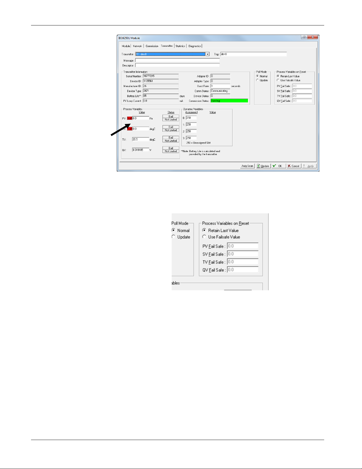
IEC62591 Wireless Interface Instruction Manual (for ROC800-Series and FloBoss 107)
Figure 4-1. NaN Warning in Transmitter screen
When NaN is reported, the RTU supports a failsafe operation defined
by the user (Retain Last Value, Use Failsafe Value).
Figure 4-2. User-defined Failsafe Operation
4.3.2 Stale / Communication Failure
If the RTU reports a Stale or Communication Failure status in the
Communication Status field, interrogate the transmitter using
475/AMS/Field Tools. The location of the transmitter’s network
diagnostics can be found the transmitter’s manual.
Additionally, if the RTU reports a Stale status, assess the physical
layout of the network. The Stale status can be triggered if there is any
kind of physical anomaly in the network (tanker trucks between
transmitter and RTU, transmitter between the end device and the RTU is
powered down, etc.).
The RTU supports gathering Diagnostic Logs of the wireless network.
You can extract these logs and send them to Technical Support for
further analysis of the network issue.
4-4 Troubleshooting Revised October 2021
Page 73

Index
IEC 62591 Wireless Interface Instruction Manual (for ROC800-Series and FloBoss 107)
A
Adding the join key ........................................... 3-24
C
Commissioning a device ............................ 3-8, 3-26
D
Decommissioning a device ........................ 3-9, 3-28
Devices
Commissioning ...................................... 3-8, 3-26
Decommissioning .................................. 3-9, 3-28
Replacing ............................................. 3-10, 3-28
E
Emerson Wireless 781S Smart Antenna ............ 1-2
F
Field Devices ...................................................... 1-4
Figures
1-1. IEC962591 Field Installation ................... 1-2
1-2. IEC 62591 Wireless Interface Module .... 1-3
1-3. Emerson Wireless 781S Smart Antenna 1-4
2-1. Mounting the 781S .................................. 2-4
2-2. 781S Mounting ........................................ 2-5
2-3. 781S Power and Data Wiring .................. 2-6
2-4. FB107 IEC 62591 Module Power and Data
Wiring to 781S ............................................ 2-7
2-5. 781S to ROC800 IEC 62591 Module Power
and Data Wiring ......................................... 2-7
3-1. Wireless Interface) .................................. 3-2
3-2. FB107 Interface with IEC 62591 Module 3-4
3-3. Network screen (FB107) ......................... 3-5
3-4. IEC 62591 Module (FB107) .................... 3-7
3-5. Commission tab (FB107) ........................ 3-8
3-6. Commissioned Device (FB107) .............. 3-9
3-7. Device Replacement Verification Dialog 3-10
3-8. Transmitter screen (FB107) .................. 3-11
3-9. Statistics screen (FB107) ...................... 3-18
3-10. Diagnostics screen (FB107) ................ 3-21
3-11. Transmitter screen (FB107) ................ 3-22
3-12. IEC 62591 Module (ROC800) ............. 3-23
3-13. Network tab (ROC800) ........................ 3-24
3-14. Commission tab (ROC800) ................. 3-26
3-15. Active Commission button (ROC800) . 3-27
3-16. Commissioned Device (ROC800) ....... 3-28
3-17. Device Replacement Verification Dialog . 3-
29
3-18. Transmitter tab (ROC800)
03-18 ........................................................ 3-29
3-19. Statistics tab (ROC800)
03-19 ........................................................ 3-36
3-20. Diagnostics tab (ROC800) .................. 3-39
3-21. Update Firmware screen (ROC800) ... 3-40
3-22. IEC 62591 Firmware Update (ROC800) . 3-
41
3-23. Attaching a USB drive ......................... 3-42
3-24. Creating the upgrade folder ................ 3-42
3-25. Copying the upgrade file ..................... 3-43
3-26. Starting ROCLINK ............................... 3-43
3-27. Verifying Run Mode ............................. 3-44
3-28. Verifying Online status ........................ 3-44
3-29. Selecting Utilities > Update Firmware . 3-45
3-30. Verifying current version ..................... 3-45
3-31. Starting the Firmware Update process 3-46
3-32. Status - Waiting for upgrade to start ... 3-46
3-33. Status -Upgrade in Progress ............... 3-47
3-34. Status -Waiting for module to reboot ... 3-47
3-35. Firmware update completed dialog ..... 3-48
3-36. Verifying version of upgraded firmware ... 3-
48
3-37. Verifying the Correct Settings ............. 3-49
4-1. Nan Warning in Transmitter tab .............. 4-4
4-2. User-defined failsafe operation ............... 4-4
H
Hardware ............................................................ 1-2
I
IEC 62591 Wireless Interface module ................ 1-2
Installation
IEC 62591 Wireless Interface module ............ 2-1
J
Join key
Adding........................................................... 3-24
M
Module
Description ...................................................... 1-3
N
Network
Accessing ..................................................... 3-24
R
Related technical information ............................. 1-5
Replacing a device ................................... 3-10, 3-28
T
Tables
1-1. Additional Technical Information ............. 1-5
Revised October 2021 Index I-1
Page 74

IEC 62591 Wireless Interface Instruction Manual (ROC800-Series and FloBoss 107)
U
Updating firmware IEC 62591 module.............. 3-41
USB port ..............................................................1-3
W
Wiring .................................................................. 2-5
I-2 Index Revised October 2021
Page 75

IEC 62591 Wireless Interface Instruction Manual (for ROC800-Series and FloBoss 107)
Revised October 2021 Index I-3
Page 76

IEC 62591 Wireless Interface Instruction Manual (for ROC800-Series and FloBoss 107)
For customer service and technical support,
Global Headquarters,
North America, and Latin America:
end-user.
Europe:
Middle East/Africa:
Asia-Pacific:
T +65 6777 8211| F +65 6777 0947
visit www.Emerson.com/SupportNet.
Emerson Automation Solutions
Remote Automation Solutions
6005 Rogerdale Road
Houston, TX 77072 U.S.A.
T +1 281 879 2699 | F +1 281 988 4445
www.Emerson.com/RemoteAutomation
Emerson Automation Solutions
Remote Automation Solutions
Unit 1, Waterfront Business Park
Dudley Road, Brierley Hill
Dudley DY5 1LX UK
T +44 1384 487200
Emerson Automation Solutions
Remote Automation Solutions
Emerson FZE
P.O. Box 17033
Jebel Ali Free Zone – South 2
Dubai U.A.E.
T +971 4 8118100 | F +971 4 8865465
Emerson Automation Solutions
Remote Automation Solutions
1 Pandan Crescent
Singapore 128461
© 2012–2021 Remote Automation Solutions, a business unit of Emerson Automation
Solutions. All rights reserved.
This publication is for informational purposes only. While every effort has been made to ensure
accuracy, this publication shall not be read to include any warranty or guarantee, express or
implied, including as regards the products or services described or their use or applicability.
Remote Automation Solutions (RAS) reserves the right to modify or improve the designs or
specifications of its products at any time without notice. All sales are governed by RAS terms
and conditions which are available upon request. RAS accepts no responsibility for proper
selection, use or maintenance of any product, which remains solely with the purchaser and/or
Remote Automation Solutions
 Loading...