

Remote Automation Solutions Guide: OpenEnterprise SignalView Reference Guide Manuals & Guides
Page 1

Reference Guide
D301537X412
April 2012
OpenEnterprise Signal View Reference
Guide (V2.83)
Remote Automation Solutions
Website: www.EmersonProcess.com/Remote
Page 2

Reference Guide
w
D301537X412
APRIL 2012
Signal Vie
Contents
1 Signal View...............................................................................................................................1
1.1 Configuration Mode.............................................................................................................1
1.1.1 Accessing the Property Pages .....................................................................................2
1.1.2 General Page ...............................................................................................................2
1.1.2.1 Floating Point Format.............................................................................................2
1.1.2.2 Width......................................................................................................................2
1.1.2.3 Precision ................................................................................................................3
1.1.2.4 Exponent................................................................................................................3
1.1.2.5 Example .................................................................................................................3
1.1.2.6 Allow Runtime Configuration..................................................................................3
1.1.2.7 Refresh Rate..........................................................................................................3
1.1.3 Signal Search Page......................................................................................................3
1.1.3.1 ControlWave Instance - Variable Search...............................................................4
1.1.3.1.1 RTU ..................................................................................................................4
1.1.3.1.2 Instance............................................................................................................4
1.1.3.1.3 Variable.............................................................................................................5
1.1.3.1.4 ControlWave Instance - Variable Result...........................................................5
1.1.3.2 ControlWave Full String Search.............................................................................5
1.1.3.2.1 RTU ..................................................................................................................5
1.1.3.2.2 String ................................................................................................................6
1.1.3.2.3 ControlWave Full String Search Result............................................................ 6
1.1.3.3 ACCOL Base-Ext-Attr Search................................................................................6
1.1.3.3.1 RTU ..................................................................................................................7
1.1.3.3.2 Base..................................................................................................................7
1.1.3.3.3 Extension..........................................................................................................7
1.1.3.3.4 Attribute ............................................................................................................7
1.1.3.3.5 ACCOL Search Result......................................................................................7
1.1.4 Signal Filters Page .......................................................................................................8
1.1.4.1 Quality Bits.............................................................................................................8
1.1.4.2 Alarm......................................................................................................................8
1.1.4.3 Control....................................................................................................................8
1.1.4.4 Manual ...................................................................................................................9
1.1.4.5 Questionable..........................................................................................................9
1.1.4.6 Logical....................................................................................................................9
1.1.4.7 High........................................................................................................................9
1.1.4.8 High-High ...............................................................................................................9
1.1.4.9 Low.........................................................................................................................9
1.1.4.10 Low-Low................................................................................................................9
1.1.4.11 In Alarm State.......................................................................................................9
1.2 Security ...............................................................................................................................9
1.2.1 OpenBSI Security.........................................................................................................9
1.2.2 OpenEnterprise Security ............................................................................................10
1.3 Runtime Mode...................................................................................................................10
1.3.1 Signal Column ............................................................................................................11
1.3.2 Alarm Bit Column........................................................................................................11
1.3.3 Control Bit Column .....................................................................................................11
1.3.4 Manual Bit Column.....................................................................................................11
- i -
Page 3

Reference Guide
w
D301537X412
APRIL 2012
Value Column.............................................................................................................11
1.3.5
1.3.6 Units Column..............................................................................................................11
1.3.7 Signal Details Dialog ..................................................................................................11
1.3.7.1 Units Column........................................................................................................12
1.3.7.2 Ack Alarm.............................................................................................................12
1.3.7.3 Signal Details with Alarm Data.............................................................................12
1.3.7.4 Status Bar Section 1 ............................................................................................13
1.3.7.5 Status Bar Section 2 ............................................................................................13
1.3.7.6 Status Bar Section 3 ............................................................................................13
1.3.7.7 Status Bar Section 4 ............................................................................................13
1.3.7.8 Status Bar Section 5 ............................................................................................13
1.3.8 Set Quality Bits Message ...........................................................................................13
1.3.9 Change Signal Value Dialog.......................................................................................13
1.4 Signal View and OEMenus ...............................................................................................14
1.4.1 Signal View Aliases....................................................................................................14
1.4.1.1 Source and Target Views.....................................................................................14
1.4.1.2 Aliases and Parameters.......................................................................................14
1.4.1.2.1 Aliases............................................................................................................14
1.4.1.2.2 Parameters.....................................................................................................15
1.4.2 Examples....................................................................................................................15
1.4.2.1 OEDesktop Custom Menu ...................................................................................15
1.4.2.1.1 Create the Signal View file.............................................................................15
1.4.2.1.2 Open OEDesktop Configuration Pages..........................................................16
1.4.2.1.3 Create a new OEDesktop Custom Menu.......................................................17
1.4.2.1.4 Configure the Menu Command......................................................................18
1.4.2.1.5 New Menu Runtime Example.........................................................................20
1.4.2.2 Alarm View Custom Menu ...................................................................................21
1.4.2.2.1 Create the Signal View file.............................................................................21
1.4.2.2.2 Add OEMenu to Alarm View File....................................................................22
1.4.2.2.3 Alarm View Menu Runtime Example..............................................................27
1.4.2.3 Graphics Custom Menu .......................................................................................28
1.4.2.3.1 Create the Signal View file.............................................................................28
1.4.2.3.2 Create a Dynamic Object ...............................................................................29
1.4.2.3.2.1 Using the Symbol Library - Tanks............................................................30
1.4.2.3.2.2 Using the Symbol Library - Cutaway Dynamic.........................................32
1.4.2.3.2.3 Add an OPC Tag as the Data Source......................................................35
1.4.2.3.2.4 Embed the Aliases into the OPC Tag......................................................36
1.4.2.3.3 Configure the Custom OEMenu.....................................................................38
1.4.2.3.3.1 Create an OEMenus Pick Object.............................................................38
1.4.2.3.3.2 Define the Target Alias.............................................................................39
1.4.2.3.4 Graphics Menu Runtime Example..................................................................45
1.4.2.3.4.1 Create a new Alarm View menu...............................................................45
1.4.2.3.4.2 Select the Alarm View Custom Menu.......................................................49
1.4.2.3.4.3 Select the Graphics View Custom Menu .................................................50
1.4.2.3.4.4 The Signal View is Opened......................................................................51
Signal Vie
2 Index .......................................................................................................................................53
- ii -
Page 4

Reference Guide
w
D301537X412
APRIL 2012
Signal Vie
1 Signal View
The Signal View connects directly with OpenBSI to read and write data to Bristol RTUs. Note that
because of this, changes made through Signal View are not recorded in the OpenEnterprise Event
Log.
1.1 Configuration Mode
In order to configure the Signal View component, it must be in Configuration Mode. The Signal View's
Property pages are then available.
1. Accessing the Property Pages
2. General Page
3. Signal Search Page
4. Signal Filters Page
- 1 -
Page 5

Reference Guide
w
D301537X412
APRIL 2012
Signal Vie
1.1.1 Accessing the Property Pages
To configure any View, the component must be placed into configure mode. This can be done in three
ways from within the Desktop.
1. Select the Desktop>>Mode>>Configure option from the Desktop's menu bar. This places
every window in the Desktop into configure mode.
2. With the View window in focus, select the File>>Mode>>Configure option from the Desktop's
menu bar. This places the selected component only into configure mode.
3. With the View window in focus, press the [Ctrl] and [M] keys on the computer keyboard
simultaneously. This will place the selected View into configure mode. Doing the same again
will toggle it back into runtime mode.
Once the View component is in configure mode, the Property Pages (which is where configuration
takes place) can be accessed by right clicking on the View and selecting the 'Propertie s' o ption, as
shown in the example below:-
1.1.2 General Page
This is the page that is displayed by default, when the Signal View is placed into configure mode. It
enables the user to configure floating point number format, access to the Property pages and refresh
rate during runtime.
1.1.2.1 Floating Point Format
This
section has options for configuring the Floating point format of numbers that appear in the 'Value'
column of the Signal View when in runtime.
1.1.2.2 Width
The num
ber of spaces reserved from the left of the value column for the display of the number.
- 2 -
Page 6

Reference Guide
w
D301537X412
APRIL 2012
This value does not truncate a number. It allows blank spaces to be displayed on the left of the
number.
In the image displayed, the number of spaces occupied by the number 1 would be 5 (i.e. 1.000 - the
decimal point counts as a space).
If the width is set to 5 spaces, and precision is set to 3, then the number will always begin on the
extreme left of the value column, since as it enlarges, it will add a space to the right of the number:-
If the width were increased to 6, then an empty space is introduced to the left of the numbers below
10 as they appear in the value column.
Signal Vie
General Page
1.1.2.3 Precision
This defin
1.1.2.4 Exponent
The type of numeri
1.1.2.5 Example
Signal View g
column in runtime.
1.1.2.6 Allow Runtime Configuration
A check here
es the number of decimal places to be displayed by the Signal View.
cal display: -
• f = 'floating point' format.
• e = exponential.
• g = 'best fit' format.
ives an example of how the configured floating point formatting will look within the value
will enable the 'Properties' option to be available in the context menu when in runtime.
1.1.2.7 Refresh Rate
This figu
re dictates the rate at which the Signal View will update its data in runtime.
1.1.3 Signal Search Page
This page enables the user to select the type of RTU and filter options. Selection of the radio buttons
on the left of the dialog changes the Search Criteria options on the right of the dialog accordingly.
- 3 -
Page 7

Reference Guide
w
D301537X412
APRIL 2012
1.1.3.1 ControlWave Instance - Variable Search
Signal Vie
The Co
the Instance and Variable parts of ControlWave signals. Wildcard characters are allowable within the
Instance and Variable fields, (* for multi-character wildcarding, and ? for single character matching). A
blank field is interpreted as a multi-character wild card.
1.1.3.1.1 RTU
ntrolWave Instance/Variable Search radio button enables search criteria to be ente red for
The user mu
display any signals from the specified RTU that meet the filter conditions. All available RTUs should
be automatically displayed in this drop-down list for selection.
1.1.3.1.2 Instance
The Instance part of a Con
(period).
st first specify an RTU from which to view signals. When in Runtime, the Signal View will
trolWave signal is defined as being all characters prior to the last full-stop,
- 4 -
Page 8

Reference Guide
w
D301537X412
APRIL 2012
1.1.3.1.3 Variable
Signal Vie
The Varia
1.1.3.1.4 ControlWave Instance - Variable Result
This is th
signals with an instance of A1 and with the characters ALARM_L at the beginning of the variable
name.
ControlWave Instance - Variable Search
ble part of a ControlWave signal name is all characters after the last full-stop, (period).
e result of the filter as applied in the Instance and Variable fields above. The filter returns all
1.1.3.2 ControlWave Full String Search
The Co
matched with the whole ControlWave signal name. Wildcard characters are allowable within the
String field, (* for multi-character wildcarding, and ? for single character matching). A blank field is
interpreted as a multi-character wild card.
ntrolWave Full String Search filter option enables a search string to be entered which is
1.1.3.2.1 RTU
The user mu
display any signals from the specified RTU that meet the filter conditions. All available RTUs should
be automatically displayed in this drop-down list for selection.
st first specify an RTU from which to view signals. When in Runtime, the Signal View will
- 5 -
Page 9

Reference Guide
w
D301537X412
APRIL 2012
1.1.3.2.2 String
Signal Vie
The String fie
1.1.3.2.3 ControlWave Full String Search Result
This is th
ld applies to the whole ControlWave signal name (Instance and variable).
e result of the full string filter shown in the ControlWave Full String Search page.
ControlWave Full String Search
1.1.3.3 ACCOL Base-Ext-Attr Search
THE AC
Extension or Attribute parts of a NW3000 signal name. Wildcard characters are allowable within the
String field, (* for multi-character wildcarding, and ? for single character matching). A blank field is
interpreted as a multi-character wild card.
COL Base-Ext-Attr search enables a search filter to be applied to any or all of the Base,
- 6 -
Page 10

Reference Guide
w
D301537X412
APRIL 2012
1.1.3.3.1 RTU
Signal Vie
The user mu
display any signals from the specified RTU that meet the filter conditions. All available RTUs should
be automatically displayed in this drop-down list for selection.
1.1.3.3.2 Base
Filter on the
for multi-character wildcarding, and ? for single character matching ).
1.1.3.3.3 Extension
Filter on the
(* for multi-character wildcarding, and ? for single character matching).
1.1.3.3.4 Attribute
Filter on the
for multi-character wildcarding, and ? for single character matching ).
1.1.3.3.5 ACCOL Search Result
This is th
with an Extension of LEVEL.
st first specify an RTU from which to view signals. When in Runtime, the Signal View will
Base part of the signal name for a NW3000 RTU. Wildcard characters are allowable (*
Extension part of the signal name for a NW3000 RTU. Wildcard characters are allowable
Attribute part of the signal name for a NW3000 RTU. Wildcard characters are allowable (*
e result of the ACCOL Base-Extension-Attribute search. The filter was set to find only signals
- 7 -
Page 11

Reference Guide
w
D301537X412
APRIL 2012
Signal Search Page
Signal Vie
1.1.4 Signal Filters Page
This page allows the user to apply further filters based on the quality bit and alarm state of signals.
Signal View Overview
1.1.4.1 Quality Bits
The first secti
enable/inhibit, Control enable/inhibit, Manual enable/inhibit, and Questionable bit set or not.
1.1.4.2 Alarm
Available opti
this control, the Signal View would filter signals on the basis of whether their Alarm quality bit was set
to 'Enable'.
1.1.4.3 Control
Available opti
this control, the Signal View would filter signals on the basis of whether their Control quality bit was
set to 'Enable'.
on of the Signal Filters dialog relates to the 'Quality Bits' of a signal. These are Alarm
ons for filtering are 'None', 'Enable' or 'Inhibit'. For example, If 'Enable' was chosen for
ons for filtering are 'None', 'Enable' or 'Inhibit'. For example, If 'Enable' was chosen for
- 8 -
Page 12

Reference Guide
w
D301537X412
APRIL 2012
1.1.4.4 Manual
Signal Vie
Available opti
this control, the Signal View would filter signals on the basis of whether their Manual quality bit was
set to 'Enable'.
1.1.4.5 Questionable
Available opti
signal which had it's Questionable bit Set would have a question mark after the value.
1.1.4.6 Logical
cking the 'Logical' check box causes the Signal View to only display logical signals that are in
Che
alarm state. When the 'Logical' check box is checked the other check boxes become disabled, since
they relate to analogue alarm states.
1.1.4.7 High
cking this box will cause the Signal View to display analogue signals that have gone into a High
Che
alarm state.
1.1.4.8 High-High
cking this box will cause the Signal View to display analogue signals that have gone into a High
Che
High alarm state.
1.1.4.9 Low
ons for filtering are 'None', 'Enable' or 'Inhibit'. For example, If 'Enable' was chosen for
ons for filtering are 'None', or 'Set'. For example, If 'Set' was chosen for this control, any
cking this box will cause the Signal View to display analogue signals that have gone into a Low
Che
alarm state.
1.1.4.10 Low-Low
cking this box will cause the Signal View to display analogue signals that have gone into a Low
Che
Low alarm state.
1.1.4.11 In Alarm State
section enables the user to filter the Signal View according to alarm state.
This
1.2 Security
Since the Signal View ActiveX control connects directly to OpenBSI, but the Signal View window is
open in the OEDesktop, which connects to the OpenEnterprise database, there are two levels of
security which apply to the Signal View:-
1. OpenBSI security
2. OpenEnterprise security.
Signal View Overview
1.2.1 OpenBSI Security
The OpenBSI security system is built on seven security levels, 0 to 6. Level 0 represents the lowest
whilst level 6 is the highest security level possible.
When configuring an RTU, each signal can be programmed with a 'Read' security level and a 'Write'
security level.
- 9 -
Page 13

Reference Guide
w
D301537X412
APRIL 2012
These are the levels of security needed to be able to read the value of the signal or to write a value to
that signal.
In order to integrate the OpenBSI security system with OpenEnterprise, the Signal View has six
security tokens corresponding to security levels 1 to 6 in OpenBSI.
Signal View Security
OpenEnterprise Security
Signal Vie
1.2.2 OpenEnterprise Security
Signal View security is governed within the OEDesktop environment by OpenEnterprise Workstation
Security. The correct application token must be given to each user of the OpenEnterprise
Workstation, who needs access to the Signal View component. Below is an example of the Security
Configuration Tool open, with an Signal View application token selected, and ready for allocating to a
user by the drag-drop method.
The user in this example would be able to log in to OpenBSI (through the Signal View) with the
read/write privileges granted to a Security Level 1 user. For more information on OpenEnterprise
Token Security and how the Security Configuration Tool works see the Security Configuration Tool
documentation.
Signal View Security
OpenBSI Security
1.3 Runtime Mode
When in Runtime mode, and configured, the Signal View looks and behaves very much like the
OpenBSI Dataview component, enabling the user to view and change NW3000 or ControlWav e
signals directly at RTU level.
- 10 -
Page 14

Reference Guide
w
D301537X412
APRIL 2012
Signal Vie
1.3.1 Signal Column
This column displays the Network 3000 name of the signal without the RTU name prefixing it. Signal
names consist of three components: Base, Extension and Attribute. These are separated by a period.
1.3.2 Alarm Bit Column
'A' stands for 'Alarm' and this column displays the status of the signal's alarm setting. Possible values
are; Blank, 'AE' - Alarm Enable and 'AI' - Alarm Inhibit.
1.3.3 Control Bit Column
'C' stands for 'Control'. This column displays the status of the signal's control setting. Possi ble values
are; 'CE' - Control Enable and 'CI' - Control Inhibit.
1.3.4 Manual Bit Column
'M' stands for 'Manual'. This column displays the status of the signal's manual setting. Possible values
are; 'ME' - Manual Enable and 'MI' - Manual inhibit.
1.3.5 Value Column
This column displays the current value of the signal in engineering units. The text in this column may
be followed by a question mark. If this is the case then this signal has been marked as 'Questionable'.
1.3.6 Units Column
If the signal has a units value associated with it, this column will display the units by which the signals
value is measured.
1.3.7 Signal Details Dialog
When a signal name is clicked on, this dialog is displayed. It provides more detailed information about
the signal, and also enables changes to be made to the signal's value, and acknowledged state, if it is
in alarm.
- 11 -
Page 15

Reference Guide
w
D301537X412
APRIL 2012
1.3.7.1 Units Column
Signal Vie
If the signal h
value is measured.
1.3.7.2 Ack Alarm
n the Ack Alarm button is selected, the alarm is acknowledged and this message is displayed.
Whe
1.3.7.3 Signal Details with Alarm Data
Whe
n the [Show Alarms>>] button is selected from the Signal Details dialog, the signal's alarms are
displayed, as shown below. Click on the [Hide Alarms<<] button to go back to the previous page.
as a units value associated with it, this column will display the units by which the signals
- 12 -
Page 16

Reference Guide
w
D301537X412
APRIL 2012
1.3.7.4 Status Bar Section 1
Signal Vie
The first, and
report the current activity of the Signal View.
1.3.7.5 Status Bar Section 2
section of the status bar displays the number of signals currently being viewed. If the signal data
This
from a particular query is still being collected then this pane will appear with a cyan background to
indicate that the number of signals is incomplete and that more data is still being returned.
1.3.7.6 Status Bar Section 3
section of the status bar is currently unused.
This
1.3.7.7 Status Bar Section 4
section of the status bar shows the security level of the current user.
This
1.3.7.8 Status Bar Section 5
section of the status bar displays the number of 'writes' pending. For example, if the user were to
This
change the value of a signal via Signal View, the value displayed in this pane is incremented by one
until the signal value change has taken effect.
largest, section of the status bar displays text messages to the user. These messages
1.3.8 Set Quality Bits Message
When any of the quality bit values of a signal are selected from the Signal View window, this message
is displayed. Selecting the [Yes] button will toggle the value.
1.3.9 Change Signal Value Dialog
This dialog, obtained by selecting a signal's value from the Signal View window enables the user to
change the value and quality bits of the selected signal.
For digital signals, the New Value field is a drop-down list containing the two possible values for the
signal, and a there is a [Toggle] button, which enables quick toggling of the value.
- 13 -
Page 17

Reference Guide
w
D301537X412
APRIL 2012
Signal Vie
1.4 Signal View and OEMenus
The Signal View component can be a Target for OEMenus. Signal View filters act as Aliases, which
can be resolved by parameters sent from the Source component, so that a Signal View file can be
opened, with its filters set based on a selection made from another view. For more details of how
OEMenus works, with an explanation of the Aliases available in the Signal View component, please
refer to the OEMenus documentation.
1. Signal View Aliases
2. Examples
1.4.1 Signal View Aliases
A full list of the Aliases belonging to the Signal View can be found on the Preset Aliases page of the
Menu Editor documentation.
1. Source and Target Views
2. Aliases and Parameters
Signal View and OEMenus
1.4.1.1 Source and Target Views
OEMenu
(the Source View) that will open up another View (the Target View), sending Parameters so that
when the Target View is opened, it displays relevant data based on what the user selected on the
Source View
1.4.1.2 Aliases and Parameters
Aliase
that has to have its value defined. Once an Alias has its value defined, it can be used as a Parameter.
It depends on whether the View is currently a Source or a Target for OEMenus.
1.4.1.2.1 Aliases
Aliase
Parameters sent by the Source View through the OEMenus interface. Aliases for most Vi ews
depend on the type of data that they display:-
s functionality enables custom menus to be created on an OpenEnterprise View component
s and Parameters are like different sides of the same coin. An Alias is an empty placeholder
s are named placeholders on the Target View, the actual value of which is resolved by the
1. Views that access tabular data (SQLView, Alarm View, Alarm Banner etc) have Aliases in the
form of column names. The Aliases match the column names.
2. Views that access data in the form of a string (i.e an OPC tag string like OEGraphics or Trend
View) use Aliases embedded into the OPC tag. The embedded Alias name is defined by
placing it inside << and >> symbols. These symbols mark the Alias. The Aliases are matched
with and resolved by parameters passed from the Source View. An example of an Alias
embedded into an OPC String would be
BristolBabcock.BristolOPCServer\"rtrdb1"."nw3000realanalog"."name:char:<<SIGNALNAME
>>"."value:float" In the case of OEGraphics, Alias names have to be identified also by the
object on which they appear.
3. Views that use strings to apply a filter to data, (i.e. the SQL View Condition string, Notes View
Default Recipient) can also use string Aliases marked with << and >>. An example would be
<<USER>> or <<DEVICENAME>>.
An Alias on an OEMenus Target View is resolved by Parameters sent to it from an OEMenus
Source View. A resolved Alias can be used as a Parameter.
- 14 -
Page 18

Reference Guide
w
D301537X412
APRIL 2012
1.4.1.2.2 Parameters
Signal Vie
A Parameter i
Constant value) that is matched with and resolves an Alias on the Target View.
s a value on the OEMenus Source View (which could be a resolved Alias, or a
1.4.2 Examples
Here are some examples of using OEMenus with Signal View as a Target.
1. OEDesktop custom menu (Constant Parameters)
2. Alarm View custom menu (Column Parameters)
3. OEGraphics custom menu (String Parameters)
1.4.2.1 OEDesktop Custom Menu
The OEDeskt
interface. When using custom OEMenus from the OEDesktop, Parameters have to be sent as
constant values, rather than as column values or as part of an OPC tag, since the OEDesktop does
not itself retrieve data directly. This means that you have to know what Aliases to match on the Target
View, and you need to send appropriate values as Parameters. These are the steps required to
create an OEDesktop custom menu that will open a single Signal View file to display various
ControlWave signals.
1. Create the Signal View file.
2. Open the OEDesktop configuration pages.
op menu bar allows you to create your own custom menus using the OEMenus
3. Create a new OEDesktop Custom Menu.
4. Configure the Menu Command.
5. Runtime example
Examples
.
1.4.2.1.1 Create the Signal View file
Follow the
se steps to create a Signal View file that will be used as a Target for OEMenus.
1. Open the OEDesktop and log in by selecting Security>Login.
2. Select OEDesktop>New from the OEDesktop menu.
- 15 -
Page 19

Reference Guide
w
D301537X412
APRIL 2012
3. Ensure that the ControlWave Instance/Variable Search option is selected on the Signal
Search page, and that no values are entered into the Instance or Variable fields.
Signal Vie
4. Select OEDesktop>Save As... and save the Signal View file to the directory where you will
keep your Signal View files.
OEDesktop Custom Menu
Alarm View Custom Menu
1.4.2.1.2 Open OEDesktop Configuration Pages
t OEDesktop>Customize... from the OEDesktop menu bar, as shown in the example below.
Selec
- 16 -
Page 20

Reference Guide
w
D301537X412
APRIL 2012
Signal Vie
OEDesktop Custom Menu
1.4.2.1.3 Create a new OEDesktop Custom Menu
On the Menu property page, select the New button, highlighted in the example below.
1.
- 17 -
Page 21

Reference Guide
w
D301537X412
APRIL 2012
2. When the dialog appears, type in the name of the new custom menu, and select the
Configure button, shown highlighted in the image below.
3. You will be presented with the OEMenus configuration interface. Review the OEMenus
documentation for instructions on how to create custom menus. Here we have created a
Menu Group called A1 signals, with two Menu Commands off it - All A1 Signals and A1 Signal
In. The All A1 Signals menu is selected, and the selected Target is OE Signal View. The
selected Action is Load File with Parameters. To help users to recognize the window, we
have given it the name All A1 Signals. Now click the Configure button, shown highlighted in
red in the image below.
Signal Vie
OEDesktop Custom Menu
1.4.2.1.4 Configure the Menu Command
After clicking
Load File with Parameters dialog.
1. Firstly, configure the File Name at the top of the dialog. Click the browse ([...]) button to the
on the Configure button on the Menu Editor dialog, you will be presented with the
right of the File field, and select the Signal View file you just created. The file and path name
will be entered into the appropriate fields on the dialog.
- 18 -
Page 22

Reference Guide
w
D301537X412
APRIL 2012
2. Next, configure the first Target Aliases and their parameters. The first will be the RTU Alias.
As you can see because this is an OEDesktop menu, and neither Column or String type
Aliases are available as Parameters, we are passing a Constant value as the Parameter.
a. First, add the Target Alias (the rtu filter), then type its intended value into the
Parameter Value field as shown in this example (the RTU is named CWM). Note, we
are providing a constant value, because we are using the OEDesktop as the Source
View, and therefore do not have any Aliases available to use as Parameters. Then
click the Add button, highlighted.
Signal Vie
b. The rtu Alias, and its value will be entered into the Parameters list,as shown in the
example below.
- 19 -
Page 23

Reference Guide
w
D301537X412
APRIL 2012
c. Now, in the same way, enter and add the instance and searchstring Aliases and their
Parameter values to the Parameters list, as shown in the image below. Note that the
searchstring parameter is a wildcard (*) character that will find all signals with an A1
instance. When done close the configuration dialog.
Signal Vie
OEDesktop Custom Menu
1.4.2.1.5 New Menu Runtime Example
n you have closed the OEDesktop property pages, you can now test the new custom menu.
Whe
1. Firstly, select the All A1 Signals option from the new CWM menu, as shown below.
2. A new window will open within the OEDesktop, showing all ControlWave signals with an A1
instance.
- 20 -
Page 24

Reference Guide
w
D301537X412
APRIL 2012
Signal Vie
OEDesktop Custom Menu
1.4.2.2 Alarm View Custom Menu
The Alarm Vi
One of the Target Aliases in the Signal View has to be resolved by concatenating the base, extension
and attribute values of the signal in alarm from the Alarm View. When resolved on the Source View by
a user selection, these column values are matched with Target View Aliases and passed to the Target
View via OEMenus. This is a list of steps required to create an OEMenu on an Alarm View that will
open a Signal View file, showing the signal selected from the Alarm View.
1. Create the Signal View file
2. Add the OEMenu to an Alarm View file
3. Alarm View Menu Runtime Example
Examples
1.4.2.2.1 Create the Signal View file
Follow the
1. Open the OEDesktop and log in by selecting Security>Login.
ew component receives and displays columnar data, so its Aliases are column values.
se steps to create a Signal View file that will be used as a Target for OEMenus.
2. Select OEDesktop>New from the OEDesktop menu.
- 21 -
Page 25

Reference Guide
w
D301537X412
APRIL 2012
3. Ensure that the ControlWave Instance/Variable Search option is selected on the Signal
Search page, and that no values are entered into the Instance or Variable fields.
Signal Vie
4. Select OEDesktop>Save As... and save the Signal View file to the directory where you will
keep your Signal View files.
OEDesktop Custom Menu
Alarm View Custom Menu
1.4.2.2.2 Add OEMenu to Alarm View File
The Source
configured.
1. Create a new Alarm View file. Select Desktop>New...
component for the OEMenu is an Alarm View. This is how the Alarm View menu is
- 22 -
Page 26

Reference Guide
w
D301537X412
APRIL 2012
Signal Vie
2. Select the Alarm View type of file from the list. We have named the new window ALARM
VIEW to aid recognition.
3. When the window loads, put it into Configure mode and select the Properties context menu.
- 23 -
Page 27

Reference Guide
w
D301537X412
APRIL 2012
4. From the General page, select the Create... button next to the OEMenus label, shown
highlighted in the example below.
Signal Vie
5. Right click on the Menu item in the Menu Editor and select the New Command option.
- 24 -
Page 28

Reference Guide
w
D301537X412
APRIL 2012
6. Select Signal View as the Target, and Load with Parameters as the Action. Then click the
Configure button, highlighted in red in the example below. Here we have decided to give the
window that will be opened by OEMenus the name SIGNAL VIEW to aid in recognition.
Signal Vie
7. On the Load File with Parameters dialog, firstly, configure the Target file, using the file
browse ([...]) button, highlighted.
8. Then configure the instance parameter, as shown.
- 25 -
Page 29

Reference Guide
w
D301537X412
APRIL 2012
Signal Vie
9. Finally, identify the searchstring Alias in the Signal View, and define it by concatenating the
base, extension and attribute column values from the Alarm View. The base, extension
and attribute columns must have an underscore character between them as shown, to match
the actual full signal name.
- 26 -
Page 30

Reference Guide
w
D301537X412
APRIL 2012
Signal Vie
Alarm View Custom Menu
1.4.2.2.3 Alarm View Menu Runtime Example
This is
how the Alarm View custom menu works in Runtime mode.
1. An alarm is selected from the Alarm View, and the new Custom Menu is selected.
- 27 -
Page 31

Reference Guide
w
D301537X412
APRIL 2012
2. The custom menu opens the Signal View file, passing the signal name of the alarm to it as a
parameter.
Signal Vie
Alarm View Custom Menu
1.4.2.3 Graphics Custom Menu
The Graphi
so it works differently to the Alarm View in terms of an OEMenus Source.
1. Create the Signal View file
2. Create a Dynamic object in Graphics View
3. Configure the custom OEMenu
4. Runtime Example
Examples
1.4.2.3.1 Create the Signal View file
Follow the
cs View (GraphWorX) component uses Aliases that are embedded into OPC Tag strings,
se steps to create a Signal View file that will be used as a Target for Graphics View.
- 28 -
Page 32

Reference Guide
w
D301537X412
APRIL 2012
1. Open the OEDesktop and log in by selecting Security>Login.
2. Select OEDesktop>New from the OEDesktop menu.
Signal Vie
3. This time we will use the Full String Search variable, because we then only need to define
one Target Alias on the Graphics custom OEMenu. Ensure that the Control W ave Full String
Search option is selected on the Signal Search page, and that no values are entered into the
String field.
4. Select OEDesktop>Save As... and save the Signal View file to the directory where you will
keep your Signal View files.
Graphics Custom Menu
1.4.2.3.2 Create a Dynamic Object
This is
create their own symbol library, but this example uses the symbol library that comes with Graphics
View.
one way that Dynamic objects are placed into Graphics View displays. Many applications
- 29 -
Page 33

Reference Guide
w
D301537X412
APRIL 2012
1. Create a Tank object from the Symbol library.
2. Add a Dynamic Cutaway object
3. Add an OPC Tag as the Data Source
4. Embed the Aliases into the OPC Tag
Graphics Custom Menu
1.4.2.3.2.1 Using the Symbol Library - Tanks
With Graphics View open select the Symbols icon from the main Drawing toolbar.
1.
Signal Vie
2. Select the 2_Misc Symbol directory.
- 30 -
Page 34

Reference Guide
w
D301537X412
APRIL 2012
Signal Vie
3. Select the 3-D ISA Tanks Symbols library.
4. Select the Tank symbol and drag it to the display page.
- 31 -
Page 35

Reference Guide
w
D301537X412
APRIL 2012
5. Resize and reposition the Tank symbol on the page.
Signal Vie
Create a Dynamic Object
1.4.2.3.2.2 Using the Symbol Library - Cutaway Dynamic
Now go back to the symbol library window and double click on the 3-D Dynamic Tank-Cut-
1.
aways.sdf library.
- 32 -
Page 36

Reference Guide
w
D301537X412
APRIL 2012
Signal Vie
2. Select the Freeform Cut-Away object and drag it to the display page as shown.
3. After resizing and positioning it, right click on it and select the Edit Symbol option.
- 33 -
Page 37

Reference Guide
w
D301537X412
APRIL 2012
Signal Vie
4. Now select the Property Inspector option.
- 34 -
Page 38

Reference Guide
w
D301537X412
APRIL 2012
5. On the Size tab of the Property pages, select the current Data Source and delete it.
Signal Vie
Create a Dynamic Object
1.4.2.3.2.3 Add an OPC Tag as the Data Source
Open a
interest. Then drag-drop the value of a particular signal into the Data Source window of the Size
Property dialog.
Database Object Viewer instance that is querying the Realanalog table for the signals of
- 35 -
Page 39

Reference Guide
w
D301537X412
APRIL 2012
Signal Vie
Create a Dynamic Object
1.4.2.3.2.4 Embed the Aliases into the OPC Tag
We must now edit the OPC Tag to embed the required Aliases into the tag string. Find the
1.
primary key part of the tag. This is the name attribute which comes after the tablename (here
realanalog) in the OPC string. Select the value that was dropped in and delete it.
2. Now begin embedding the Aliases. First, the RTU name followed by a colon (:) is entered as
normal text, then the INSTANCE Alias is created by enclosing it within << and >> symbols.
This is how we are going to embed all of the required Aliases into the OPC tag. The Alias is
then followed by a period, because the INSTANCE part of the signal name is followed by a
period. The period is interpreted as normal text.
- 36 -
Page 40

Reference Guide
w
D301537X412
APRIL 2012
Signal Vie
3. After this, the BASE Alias is entered, followed by an underscore, followed by the EXTENSION
Alias and an underscore. Finally, the ATTRIBUTE Alias is added. ControlWave signal names
are constructed like that in the OpenEnterprise database. Now, when we open this display as
an OEMenus Target, as long as we send the instance, base, extension and attribute
values as Parameters, this OPC tag will be resolved. Note, we have named this object as
VALUETAG. This is necessary for identification when using this display as a Source View for
OEMenus to call the Signal View file we created earlier.
Create a Dynamic Object
- 37 -
Page 41

Reference Guide
w
D301537X412
APRIL 2012
1.4.2.3.3 Configure the Custom OEMenu
Signal Vie
That is the Dynamic obj
open this display as a Target of OEMenus, the Size object will pick up the signal's value and display it
as a Tank Level. Now we shall consider how to use the display as a Source for OEMenus to open a
Signal View file and display the same signal in the Signal View file that is display in this Graphics
display.
1. Create an OEMenus Pick Object
2. Define the Target Alias
Graphics Custom Menu
1.4.2.3.3.1 Create an OEMenus Pick Object
This is
object on the Tank image, but we will create it by using a Command Button.
not the only way to create a Pick object. We could just as easily create a new Dynamic Pick
1. Drop a Command Button onto the page, then open the Properties dialog and select the Pick
tab. Select Custom Command from the Action drop-down list, as shown in the example
below, then click the Custom button shown highlighted in red on the image.
ect created. Now, as long as we define values for the Aliases whenever we
2. This opens the Menu Editor dialog. For more information on how to create custom
OpenEnteprise menus using the OEMenu Editor see the OEMenus documentation. Create a
new Menu Command named SIGNAL VIEW. The Target is set to OE Signal View, and the
Action is set to Load File with Parameters. Then click the Configure... button to open the
Load file with parameters dialog.
- 38 -
Page 42

Reference Guide
w
D301537X412
APRIL 2012
Signal Vie
Configure the Custom OEMenu
1.4.2.3.3.2 Define the Target Alias
On the Load
Signal View file. We will define this as a string containing multiple resolved Aliases from the Graphics
View display file (.GDF extension) we have just created.
1. Firstly, on the Load File with Parameters dialog, use the browse button (highlighted in red in
2. Now, type the Target Alias (searchstring) into the Target column or alias field, and then the
file with parameters dialog, the Target Alias will be the signalsearch variable in the
the image below) to find the Target Signal View file created previously.
first Source Alias (INSTANCE), plus the name of the object into the appropriate fields. Then
click the Insert button.
- 39 -
Page 43

Reference Guide
w
D301537X412
APRIL 2012
Signal Vie
3. This adds the INSTANCE Alias to the Parameter Value field. Type a period after the
INSTANCE Alias in the Parameter Value field. Then type the BASE Alias into the Alias field.
Leave VALUETAG in the Object name field, because all of the required Aliases are on this
one object. Now click the Insert button once more.
- 40 -
Page 44

Reference Guide
w
D301537X412
APRIL 2012
Signal Vie
4. The BASE Alias is added to the Parameter Value field. Type an underscore after the BASE
alias in the Parameter Value field. Then type EXTENSION into the Alias, and click the Insert
button again.
- 41 -
Page 45

Reference Guide
w
D301537X412
APRIL 2012
Signal Vie
5. The EXTENSION Alias is added to the Parameter Value field. Type an underscore after this
Alias as for the BASE Alias. Then enter the ATTRIBUTE Alias in the Alias field and click the
Insert button.
- 42 -
Page 46

Reference Guide
w
D301537X412
APRIL 2012
Signal Vie
6. The whole searchstring Parameter Value is now entered. Before closing, click the Add
button to add this to the Parameters List.
- 43 -
Page 47

Reference Guide
w
D301537X412
APRIL 2012
Signal Vie
7. The Parameter name and definition are now entered into the Parameters List. The name of
the Object on which the defined Aliases are to be found is also stored in this list.
- 44 -
Page 48

Reference Guide
w
D301537X412
APRIL 2012
Signal Vie
Configure the Custom OEMenu
1.4.2.3.4 Graphics Menu Runtime Example
To demo
custom OEMenus, we will now create a new custom menu on the original Alarm View file, which calls
the new Graphics View file, passing Parameters to it. Then we will open the Signal View file we
created in these examples from the OEMenu on the Graphics View file.
Graphics Custom Menu
1.4.2.3.4.1 Create a new Alarm View menu
nstrate how the new Graphics View file that we have created can be a Target and Source for
1. Create a new custom menu on the Alarm View
2. Select the Alarm View Graphic View menu
3. Select the Graphics View Signal View menu
4. The Signal View is opened
Open the Alarm View file in OEDesktop and place it into Configure mode (Ctrl-M). Select the
1.
Properties context menu.
- 45 -
Page 49

Reference Guide
w
D301537X412
APRIL 2012
2. Click the Edit... button on the General page.
Signal Vie
3. Create a new command called GRAPHICS VIEW. Select Bristol Babcock OpenEnterprise
Display in the Target field and Load File with Parameters in the Action field. Then click the
Configure button.
- 46 -
Page 50

Reference Guide
w
D301537X412
APRIL 2012
Signal Vie
4. Find the Target Signal View file using the browse button. Then type INSTANCE into the
Target column or alias to resolve field, and select the instance column from the Column
list. Click the Insert button, then the Add button.
- 47 -
Page 51

Reference Guide
w
D301537X412
APRIL 2012
Signal Vie
5. The INSTANCE parameter and its definition are entered into the Parameters list. Do the
same thing with the BASE, EXTENSION and ATTRIBUTE Target parameters, paring each
one with the column of the same name. When this is done click the OK button to close the
Load file with parameters dialog.
- 48 -
Page 52

Reference Guide
w
D301537X412
APRIL 2012
Signal Vie
Graphics Menu Runtime Example
1.4.2.3.4.2 Select the Alarm View Custom Menu
Load the Ala
as shown.
rm View file into the OEDesktop and select the GRAPHICS VIEW custom menu option,
- 49 -
Page 53
Reference Guide
w
D301537X412
APRIL 2012
Signal Vie
Graphics Menu Runtime Example
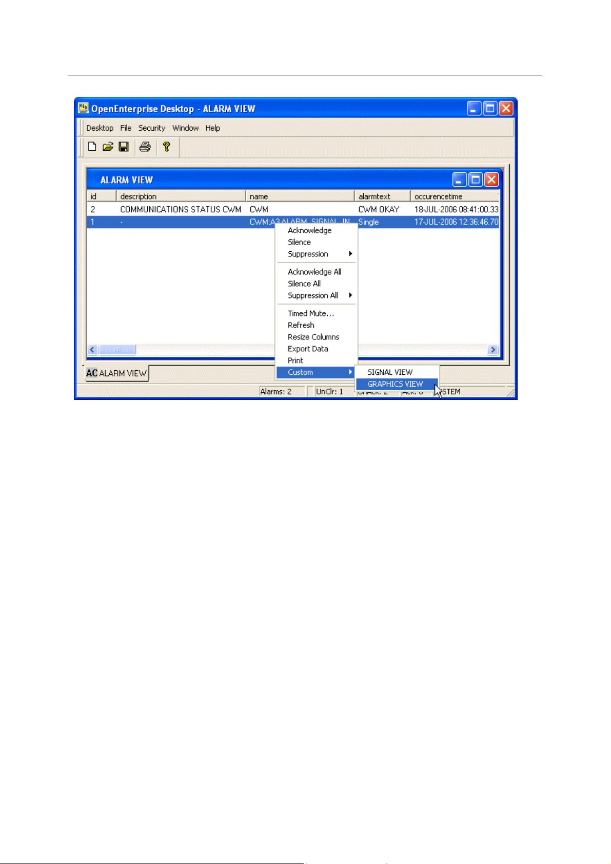
1.4.2.3.4.3 Select the Graphics View Custom Menu
The Graphi
was selected from the Alarm View. Now select the LOAD SIGNAL VIEW button, which contains our
custom menu.
cs View file is opened with the Parameters passed, so that the same signal is on view that
- 50 -
Page 54

Reference Guide
w
D301537X412
APRIL 2012
Signal Vie
Graphics Menu Runtime Example
1.4.2.3.4.4 The Signal View is Opened
The Signal Vi
the same signal is displayed in the Signal View component.
ew file is opened with the Parameters now passed from the Graphics View file, so that
- 51 -
Page 55

Reference Guide
w
D301537X412
APRIL 2012
Signal Vie
Graphics Menu Runtime Example
- 52 -
Page 56

Reference Guide
w
D301537X412
APRIL 2012
2 Index
1
A
Accessing........................................................... 4
Property Pages............................................... 4
Ack Alarm......................................................... 14
Alarm................................................................ 11
Alarm Bit Column............................................. 13
Alarm Data ....................................................... 14
Alarm State ...................................................... 12
Allow Runtime Configuration.............................. 6
Attribute............................................................ 10
B
Base................................................................. 10
C
Change Signal Value Dialog............................ 16
Control.............................................................. 11
Control Bit Column........................................... 13
E
Example ............................................................. 6
Exponent............................................................ 6
Extension.......................................................... 10
F
Floating............................................................... 5
Point Format................................................... 5
G
General Page..................................................... 5
H
High.................................................................. 11
High high.......................................................... 12
Signal Vie
Manual Bit Column............................................13
O
OpenBSI Security .............................................12
OpenEnterprise Security...................................12
P
Point Format .......................................................5
Floating............................................................5
Precision.............................................................6
Property Pages...................................................4
Accessing........................................................4
Q
Quality Bits........................................................11
Questionable.....................................................11
R
Refresh Rate.......................................................6
RTU...........................................................7, 8, 10
Runtime Interface..............................................13
S
Set Quality Bits Message..................................15
Signal Column...................................................13
Signal Details....................................................14
Signal Details Dialog.........................................14
Signal Filters Page............................................10
Signal Search Page............................................6
Signal View Overview.........................................4
Status Bar Section............................................15
U
Units Column ....................................................14
L
Logical.............................................................. 11
Low................................................................... 12
Low-Low........................................................... 12
M
Manual.............................................................. 11
V
Value Column ...................................................14
W
Width...................................................................5
- 53 -
Page 57

Page 58

Reference Guide
D301537X412
APRIL 2012
DISCLAIMER
Bristol, Inc., Bristol Babcock Ltd, Bristol Canada, BBI SA de CV and the Flow Computer Division , are wholly owned subsidiaries of Emerson Electric Co. doing business
as Remote Automation Solutions (“RAS”), a division of Emerson Process Management. ROC, FloBoss, ROCLINK, Bristol, Bristol Babcock, ControlWave, TeleFlow and
Helicoid are trademarks of RAS. AMS, PlantWeb and the PlantWeb logo are marks of Emerson Electric Co. The Emerson logo is a trademark and service mark of the
Emerson Electric Co. All other marks are property of their respective owners.
The contents of this publication are presented for informational purposes only. While every effort has been made to ensure informational accuracy, they are not to be
construed as warranties or guarantees, express or implied, regarding the products or services described herein or their use or applicability. RAS reserves the right to
modify or improve the designs or specifications of such products at any time without notice. All sales are governed by RAS’ terms and conditions which are available upon
request. RAS does not assume responsibility for the selection, use or maintenance of any product. Responsibility for proper selection, use and maintenance of any RAS
product remains solely with the purchaser and end-user.
Engineered and supported by:
Remote Automation Solutions,
Blackpole Road, Worcester, WR3 8YB, UK
Registered office: Meridian East, Leicester, LE19 1UX
Registered in England and Wales, Registration No. 00671801
VAT Reg No. GB 705 353 652
Emerson Process Management
Remote Automation Solutions
1100 Buckingham St
Watertown, CT 06795
T 1 (860) 945 2200
F 1 (860) 945 2278
www.EmersonProcess.com/Remote
binfo@EmersonProcess.com
© 2001-2012 Remote Automation Solutions, division of Emerson Process Management. All rights
reserved.
Emerson Process Management
Remote Automation Solutions
Blackpole Road
Worcester, WR3 8YB
T 44 (0) 1905 856848
F 44 (0) 1905 856930
www.EmersonProcess.com/Remote
oedsupport@EmersonProcess.com
 Loading...