

Remote Automation Solutions Guide: OpenEnterprise NW3000 Setup Reference Guide Manuals & Guides
Page 1

Reference Guide
D301509X412
April 2012
OpenEnterprise NW3000 Setup
Reference Guide (V2.83)
Remote Automation Solutions
Website: www.EmersonProcess.com/Remote
Page 2

Reference Guide
D301509X412
April 2012
NW3000 Setup
Contents
1 NW3000 Setup Tool .................................................................................................................1
1.1 Starting the NW3000 Setup Tool ........................................................................................1
2 Main Dialog...............................................................................................................................1
2.1 File Menu ............................................................................................................................2
2.2 Help Menu...........................................................................................................................2
2.3 System Set-up Button .........................................................................................................2
2.4 Device Set-up Button ..........................................................................................................2
2.5 Advanced Button.................................................................................................................2
2.6 Cancel Button......................................................................................................................2
3 System Setup Wizard..............................................................................................................3
3.1 OpenBSI AutoStart..............................................................................................................3
3.1.1 Automatically Start OpenBSI........................................................................................4
3.1.2 Automatically Stop OpenBSI........................................................................................4
3.1.3 Network Definition File..................................................................................................4
3.1.4 Number of seconds between subsequent start attempts.............................................4
3.1.5 Number of times to retry OpenBSI start-up..................................................................4
3.1.6 Cancel Button...............................................................................................................4
3.1.7 Help Button...................................................................................................................5
3.2 Message Buffers .................................................................................................................5
3.2.1 Maximum total number of pending requests................................................................5
3.2.2 Maximum number of pending requests per device ......................................................6
3.3 Device Health Checking......................................................................................................6
3.3.1 Number of seconds between device health checks.....................................................7
3.3.2 Number of devices per health check............................................................................7
3.3.3 Number of consecutive failures allowed.......................................................................7
3.4 Remote Alarm Support........................................................................................................7
3.4.1 Enable Remote Alarm Support.....................................................................................8
3.4.2 Acknowledge Return to Normal Reports......................................................................8
3.4.3 Critical...........................................................................................................................8
3.4.4 Non-Critical...................................................................................................................9
3.4.5 Operator Guide.............................................................................................................9
3.4.6 Event.............................................................................................................................9
3.5 RBE Support .......................................................................................................................9
3.5.1 RBE Data Collection...................................................................................................10
3.6 Polling................................................................................................................................10
3.6.1 Active Polling for NW3000 Analogs............................................................................11
3.6.2 Active Polling for NW3000 Digitals.............................................................................11
3.6.3 Active Polling for NW3000 Strings .............................................................................11
3.6.4 Active Polling Frequency............................................................................................11
3.6.5 Include RBE Signals in Active Polling........................................................................12
3.6.6 Background Polling Frequency...................................................................................12
3.6.7 One Shot Poll..............................................................................................................12
3.6.8 Maximum Interval.......................................................................................................12
3.6.9 Offset..........................................................................................................................12
3.6.10 Analog Alarms.........................................................................................................13
- i -
Page 3

Reference Guide
D301509X412
April 2012
Signal Import Options........................................................................................................13
3.7
3.8 System Set-up Summary..................................................................................................17
3.8.1 System Setup Finish Button.......................................................................................18
4 Device Setup Wizard.............................................................................................................18
4.1 Import From Netview.........................................................................................................19
4.1.1 All Devices..................................................................................................................19
4.1.2 Single Device..............................................................................................................20
4.2 RBE Support .....................................................................................................................20
4.2.1 Use Settings ...............................................................................................................20
4.2.2 Enable RBE Data Collection for Device.....................................................................21
4.2.3 Scan Rate...................................................................................................................21
4.2.4 Scan Slice...................................................................................................................21
4.2.5 Timeout.......................................................................................................................21
4.2.6 StopXmit.....................................................................................................................22
4.3 Polling Support..................................................................................................................22
4.3.1 Use Settings Here for Polling Support........................................................................23
4.3.2 Create a Unique Timeclass for each Device..............................................................23
4.3.3 Polling Frequency.......................................................................................................23
4.4 Device Setup Summary ....................................................................................................23
4.4.1 Device Setup Finish Button........................................................................................25
NW3000 Setup
5 Index .......................................................................................................................................26
- ii -
Page 4

Reference Guide
D301509X412
April 2012
NW3000 Setup
1 NW3000 Setup Tool
The NW3000 Setup Tool enables the user to both populate a Server database and configure the data
collection for Bristol devices. This Wizard based tool guides the user quickly and easily through the
necessary steps of configuration for the following:-
• OpenBSI start-up
• Message Buffer usage
• Device health checking
• Remote Alarm Support
• RBE data collection
• Logical Alarm Background Polling
• Importing of Signal and MSD data
• Scheduled data collection (polling)
1.1 Starting the NW3000 Setup Tool
The NW3000 Setup Tool can be located in the Toolbox.
Toolbox is launched from the Windows Start menu. Double click on the NW3000 Setup icon to then
launch the NW3000 Setup Tool.
2 Main Dialog
The NW3000 Setup Tool's main page allows the user to configure system and device specific
properties. It also provides for the automatic import of device signals into the Server database.
- 1 -
Page 5

Reference Guide
D301509X412
April 2012
NW3000 Setup
2.1 File Menu
The File menu has only one option - Exit. Select this to exit the NW3000Setup program.
2.2 Help Menu
The Help Menu provides access to this Help file, and to the 'About' box. This provides information
about the product version, together with relevant contact information.
2.3 System Set-up Button
The 'System Set-up' button starts the System Set-up wizard. This will guide you through the process
of setting up system wide start-up and data collection behaviour.
2.4 Device Set-up Button
The 'Device Set-up' button starts the Device Set-up wizard. This will guide you through the process of
importing device signals into the Server database as well as the configuration of data collection.
2.5 Advanced Button
This button will display a set of property pages, which will enable the user to view and modify settings
for Bristol devices. It should not be used until the devices have been first set-up and the signals built
into the database.
Advanced Property Pages
2.6 Cancel Button
If selected, the NW3000 Setup tool will close.
- 2 -
Page 6

Reference Guide
D301509X412
April 2012
NW3000 Setup
3 System Setup Wizard
This wizard enables the user to set up key settings for the NW3000 Driver regarding:
1. OpenBSI AutoStart
2. Message Buffers
3. Device Health Checking
4. Remote Alarm Support
5. RBE Support
6. Polling
7. Signal Import Options
3.1 OpenBSI AutoStart
This is the first dialog of the 'System Set-up' wizard. It enables the user to configure the automatic
starting and stopping of OpenBSI by ObjectServer / OpenEnterprise.
- 3 -
Page 7

Reference Guide
D301509X412
April 2012
NW3000 Setup
3.1.1 Automatically Start OpenBSI
If checked, then OpenBSI will be started automatically when the NW3000 driver starts. If this box is
checked, then you must create and set the following values on the OpenEnterprise\Tasks\RDI3000
key in the Settings Editor.
Name Description
EnableBSAUTO Set to 1 to use BSAUTO to start OpenBSI. Used in
conjunction with BSAUTOFormatString.
When set to 0, the BSIStartSys API call will be
used to start OpenBSI.
Default value is 0.
BSAUTOFormatString The format string used as the BSAUTO command
line.
Default value is "BSAUTO -std SYSTEM SYSTEM
%s" where %s represents the NDF filename
specified within the nw3000driver. obsistartndf
attribute.
3.1.2 Automatically Stop OpenBSI
If checked, then OpenBSI will be stopped automatically when the NW3000 driver stops.
3.1.3 Network Definition File
This is the Network Definition File used by OpenBSI to define the network of Bristol devices. It has an
extension of .NDF, is usually named 'Current.ndf' and by default resides within the 'C:\Accol'
directory. Use the browse button to locate the correct file. Once selected, the file's full pathname will
be placed into the Network Definition File text field.
3.1.4 Number of seconds between subsequent start attempts
This is the number of seconds the NW3000 driver will wait between failed attempts to start OpenBSI.
The default value is sixty seconds. This can be changed by typing another value directly into the field
or using the buttons provided.
3.1.5 Number of times to retry OpenBSI start-up
The number of times the NW3000 driver will retry starting OpenBSI, should startup fail. Defaults to
zero (0). This can be changed by typing an new value into the field or using the buttons provided.
3.1.6 Cancel Button
If selected, the dialog will close. No changes made on this dialog or the previous dialogs in the wizard
will be saved.
- 4 -
Page 8

Reference Guide
D301509X412
April 2012
NW3000 Setup
3.1.7 Help Button
Selection of this button will display the help topic for this dialog.
3.2 Message Buffers
The Message Buffers dialog enables the user to configure the maximum number of pending requests
for the system as a whole and per device.
3.2.1 Maximum total number of pending requests
The default value is zero (0), in which case the NW3000 Driver will accept the pending message
request buffers settings configured within OpenBSI. It should not be set to more than that set by
OpenBSI.
If the default value is not chosen, the selected maximum number of pending requests should be less
than the total number available within OpenBSI. The value chosen should not be so high that it could
adversely affect other OpenBSI clients or cause excessive network loading.
- 5 -
Page 9
Reference Guide
D301509X412
April 2012
NW3000 Setup
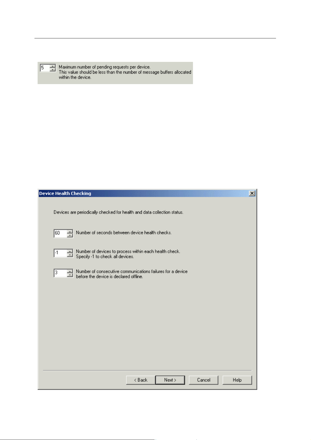
3.2.2 Maximum number of pending requests per device
Specifies the maximum number of pending requests that a device can have at any one time. The
default value is 5. When changing the value the following points should be taken into account:-
1. The value should be significantly less than the number of message buffers allocated within
the device.
2. The nature of the network communications between the Server and the devices. A single
serial link would, for instance, indicate a lower buffer value than a 100BaseT IP network link.
3. The number of devices and network levels used. More devices and network levels would
indicate a lower pending request buffer number per device.
3.3 Device Health Checking
The Device Health Checking dialog enables the user to configure how devices are checked for health
and data collection status.
- 6 -
Page 10
Reference Guide
D301509X412
April 2012
NW3000 Setup
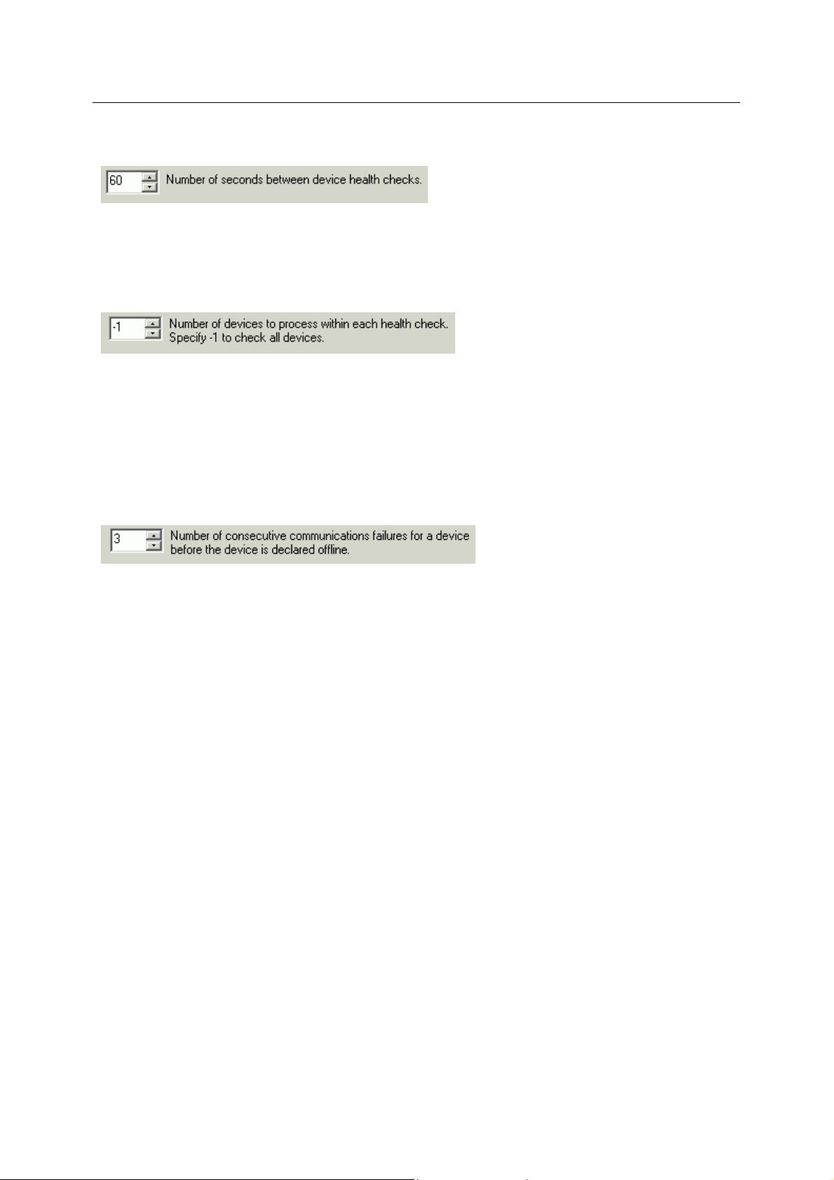
3.3.1 Number of seconds between device health checks
Default is 60 seconds. This figure controls the frequency of device health checks. It may need to be
made larger if there are a lot of devices and more than one level in the network that links the devices,
or the number of devices to check per time may need to be made smaller.
3.3.2 Number of devices per health check
This is the number of devices to check within the time period allowed. On large telemetry systems it
may be beneficial to set this number to check a smaller number of devices during the health check
period.
For instance, if there were 120 devices, and a health check period of 60 seconds, the Server could be
configured to check 30 devices per health check, rather than doing them all within one health check
period. In such an example all devices would receive a health check every four minutes.
3.3.3 Number of consecutive failures allowed
The number of consecutive communications failures to a particular device before it is declared offline.
The time taken for this to happen will depend on the communications loading and freque ncy between
the Server and the device.
3.4 Remote Alarm Support
The Remote Alarm Support dialog enables the user to switch on Remote Alarm Support, and to select
priorities for which users must acknowledge 'Return-to-Normal' reports. By default, Return-to-Normal
alarm reports do not require user acknowledgement.
- 7 -
Page 11

Reference Guide
D301509X412
April 2012
NW3000 Setup
3.4.1 Enable Remote Alarm Support
If checked, the NW3000 Driver will register with OpenBSI for the receipt of remote alarm reports.
3.4.2 Acknowledge Return to Normal Reports
Uncleared alarms require acknowledgement, but by default return-to-normal alarms do not require
user acknowledgement. Network3000 device alarms can also be set to require acknowledgement
when the signal value returns to normal.
This section enables the user to select the alarm priorities for which the acknowledgement of a return
to normal condition is required.
3.4.3 Critical
If checked, critical priority return-to-normal alarm reports will require user acknowledgement.
- 8 -
Page 12
Reference Guide
D301509X412
April 2012
NW3000 Setup
3.4.4 Non-Critical
If checked, non-critical priority return-to-normal alarm reports will require user acknowledgement.
3.4.5 Operator Guide
If checked, operator-guide priority return-to-normal alarm reports will require user acknowledgement.
3.4.6 Event
If checked, event priority return-to-normal alarm reports will require user acknowledgement.
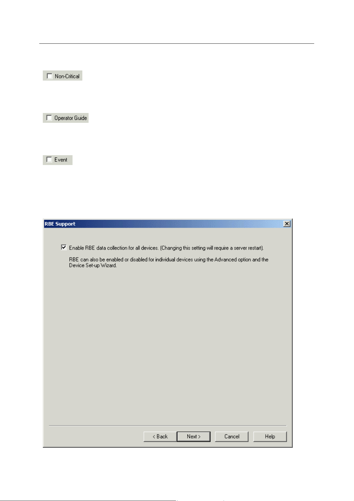
3.5 RBE Support
The RBE Support dialog enables the user to configure Report By Exception (RBE) data collection for
all devices.
- 9 -
Page 13
Reference Guide
D301509X412
April 2012
NW3000 Setup
3.5.1 RBE Data Collection
When checked, RBE data collection will be automatically enabled for all devices that contain one or
more RBE signals.
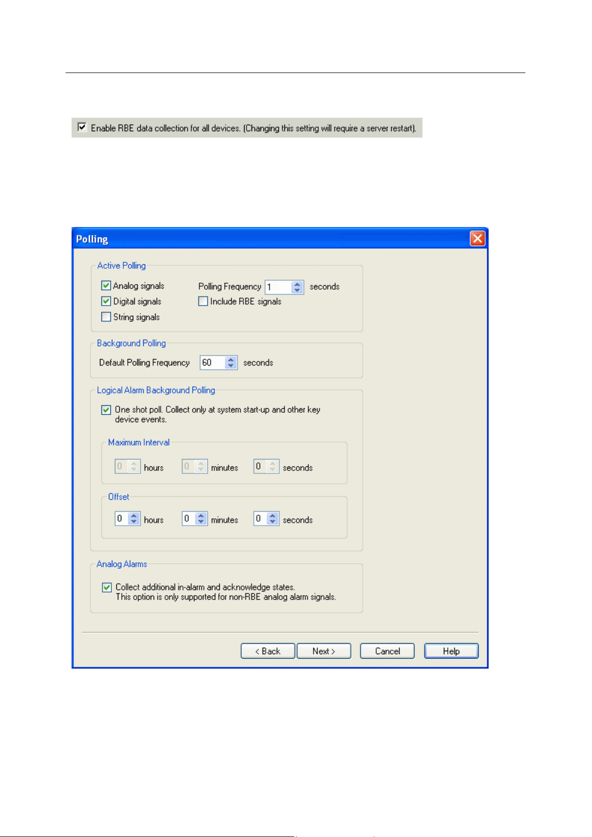
3.6 Polling
The Polling dialog enables the user to configure polled data collection.
- 10 -
Page 14

Reference Guide
D301509X412
April 2012
NW3000 Setup
3.6.1 Active Polling for NW3000 Analogs
When this box is checked, Active Polling for NW3000 realanalog signals is enabled. By default analog
signals will be enabled for Active Polling, so this box is checked.
3.6.2 Active Polling for NW3000 Digitals
When this box is checked, Active Polling for NW3000 Digital signals is enabled. By default digital
signals will be enabled for Active Polling, so this box is checked.
3.6.3 Active Polling for NW3000 Strings
When this box is checked, Active Polling for NW3000 String signals is enabled. By default string
signals will not be enabled for Active Polling, so this box is unchecked.
3.6.4 Active Polling Frequency
The frequency that will be set for Active Polling templates. The default frequency for Active Polling is
1 second.
- 11 -
Page 15

Reference Guide
D301509X412
April 2012
NW3000 Setup
3.6.5 Include RBE Signals in Active Polling
When this box is checked, RBE signals will also be included in any Active Poll Lists that are created.
By default RBE signals are not included in Active Polling, so this box is unchecked.
3.6.6 Background Polling Frequency
The frequency at which normal background polling will take place. The default value for background
polling is set at 60 seconds. This value is applied when importing new devices, but the value can be
overridden for individual devices from the 'Polling Support Page' when using the 'Device Setup
Wizard'.
3.6.7 One Shot Poll
If checked, Logical Alarms will only be polled when the Server starts up and at other key device
events.
When checked, the Maximum Interval time fields will be disabled.
3.6.8 Maximum Interval
Specifies the time between successive polls for Logical Alarms. This is only available if the 'One Shot
Poll' option is not selected.
3.6.9 Offset
Specifies an offset period on start up of the Server for polling of Logical Alarms.
- 12 -
Page 16

Reference Guide
D301509X412
April 2012
NW3000 Setup
3.6.10 Analog Alarms
If checked, the following additional alarm states will be collected for analog signals that are not
designated as RBE.
InHiHiAlarm
InHiAlarm
InLoAlarm
InLoLoAlarm
HighHighAcknowledged
HiAcknowleged
LoAcknowledged
LoLoAcknowledged
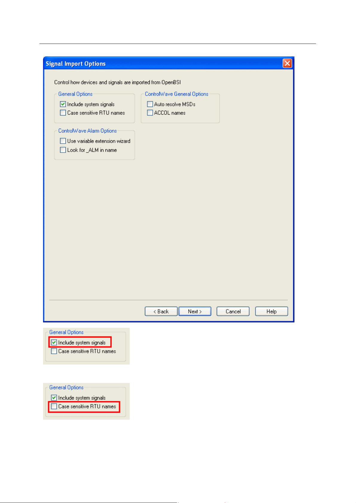
3.7 Signal Import Options
This dialog enables the user to fine tune their database build. The options apply to the NW3000
Database Builder, and affect how it builds Bristol signals into the database.
- 13 -
Page 17
Reference Guide
D301509X412
April 2012
NW3000 Setup
If checked, this option will ensure that device system signals are included in the database build.
Enables RTU names with mixed upper and lower case characters to be defined (e.g. Memphis,
Area1) when adding devices and signals into the OpenEnterpriseObjectServer database. By default,
all RTU names are converted to uppercase in the database (e.g. MEMPHIS, AREA1).
- 14 -
Page 18

Reference Guide
D301509X412
April 2012
If a build occurs for an RTU with mixed case characters without this option checked, the RTU name
will be inserted into the database in upper case characters, and all its signals will be preceded and
identified by the uppercase RTU name followed by a colon (e.g. MEMPHIS:PUMP1.RUNNING.001).
If a subsequent build for the same RTU occurs, but with this option checked, the NW3000 Dat abase
Builder will ask for confirmation before inserting the device and its signals into the database.
This time, the mixed case name will be used. The previous entries for the same device and its signals
with the capitalized name will NOT be deleted from the database. However, the NW3000 Database
Builder will only now recognize the capitalized name for the RTU.
NW3000 Setup
- 15 -
Page 19

Reference Guide
D301509X412
April 2012
NW3000 Setup
Checking this box will ensure that the DataBase Builder resolves the Control Wave device signal
addresses, also known as MSD (Master Signal Directory) numbers. This must be checked in order for
the Poll List Builder to create poll lists for Control Wave device's.
- 16 -
Page 20
Reference Guide
D301509X412
April 2012
When selected, ControlWave signal names will be converted to ACCOL signal name form at (i.e.
<BASE>.<EXTENSION>.<ATTRIBUTE>).
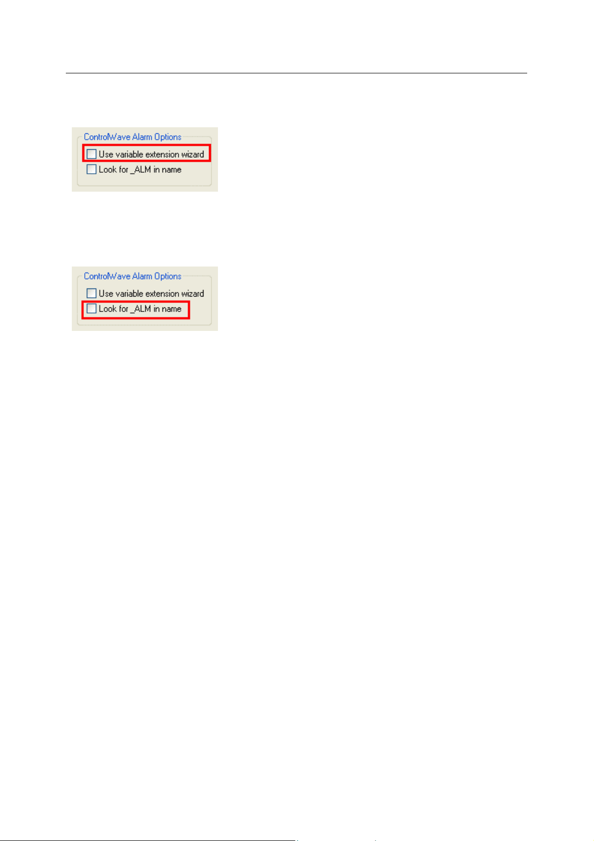
When checked, the NW3000 Database Builder will use the 'Variable Extension Wizard' settings from
the ControlWave load to determine alarm signals for ControlWave RTUs.
The default setting is for this and the 'Look for _ALM in name' option to be unchecked. This causes
the NW3000 Database Builder to mark all signals as alarms.
NW3000 Setup
When checked, the NW3000 Database Builder will look for signals with names that contain '_ALM' to
determine alarm signals for ControlWave RTUs.
The default setting is for this and the 'Use variable extension wizard' option to be unchecked. This
causes the NW3000 Database Builder to mark all signals as alarms.
3.8 System Set-up Summary
This is the final dialog displayed for the 'System Set-up' wizard. It enables the user to view the
configuration parameters defined. Should anything require changing, the user is able to navig ate back
to the appropriate dialog to make the necessary changes prior to finalizing the system configuration.
Selecting the [Finish] button will update the server database with the requested configuration.
- 17 -
Page 21

Reference Guide
D301509X412
April 2012
NW3000 Setup
3.8.1 System Setup Finish Button
When this button is selected the server database will be updated with the user-defined configuration.
A successful update of the user configuration will be confirmed by the following message.
Selection of the [Yes] button will display the Devices wizard.
4 Device Setup Wizard
This wizard enables the user to set up key Device settings for the NW300 0 Driver, such as:
1. Import From Netview
2. RBE Support
- 18 -
Page 22

Reference Guide
D301509X412
April 2012
3. Polling Support
At the end of the wizard, the Summary page displays the settings that have been chosen for final
checking. When the [Finish] button on this dialog is selected, the NW3000 Database Builder is
started, followed by the NW3000 Poll List Builder and the signals are imported into the database, and
background templates (poll lists) are created.
NW3000 Setup
4.1 Import From Netview
The Import From Netview dialog enables the user to both import signal data into the server database
as well as configure the system data collection from the device network.
The user can choose to import all devices or a selected device.
4.1.1 All Devices
If checked, signal data from the application load files will be imported into the server database for all
devices listed.
- 19 -
Page 23

Reference Guide
D301509X412
April 2012
If this is the first use of the wizard, all signals will be added along with their MSD data. On subsequent
runs of the wizard, only new signals will be added, whilst the MSD's will be updated to resolve any
load version mismatches.
Note: An MSD number specifies a signal's memory location and is used for efficient template and
RBE data collection.
NW3000 Setup
4.1.2 Single Device
When checked, the device list becomes enabled, and the user is able to select a single device from
those listed. Note: The RTUs listed are those defined within the OpenBSI network definition file.
4.2 RBE Support
The RBE Support dialog enables the user to configure RBE communication parameters for the
selected device(s).
4.2.1 Use Settings
- 20 -
Page 24
Reference Guide
D301509X412
April 2012
When checked, the 'RBE Settings' section of this dialog will become enabled. The user is then able to
specify RBE settings for the selected device(s). These will then override any RBE settings co nfigured
at the device, or the default settings created for the device.
If the RBE Module mode at the device is set to 1, then the RBE parameters assigned locally to the
module define the the RBE collection for the device.
If the RBE Module mode at the device is set to 0, then the values configured via this dialog are used
to define the RBE collection. The user should check that the defaults supplied by Server are suitable
for the application.
NW3000 Setup
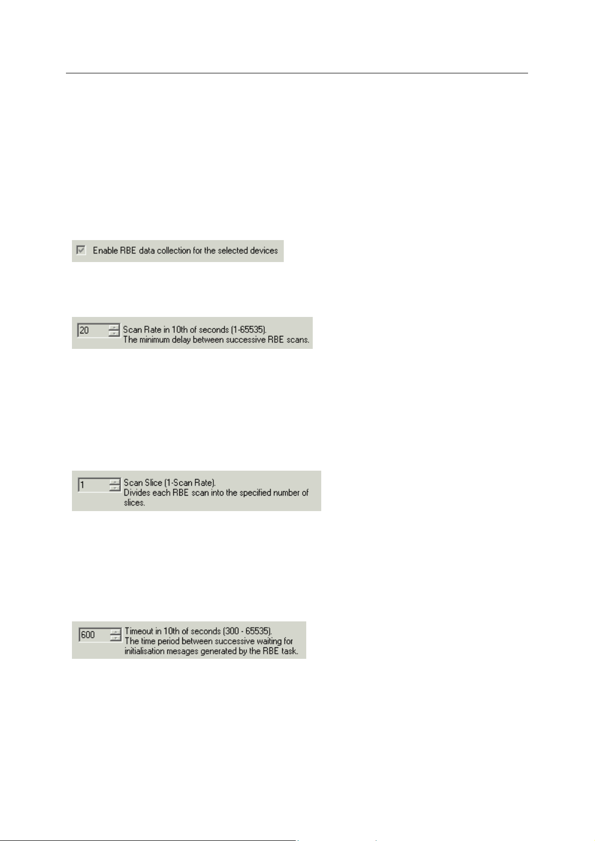
4.2.2 Enable RBE Data Collection for Device
When checked, RBE data collection will be enabled for the selected device(s).
4.2.3 Scan Rate
The scan rate is the rate at which the RBE signals are checked to determine whether any exceptions
have occured. The value is in tenths of a second and may range from 1.0 (0.1) seconds to 65535.0
(6553.5) seconds.
Note: If the scan rate is small (too fast) it may cause scanning to occur continuously. This may
interfere with other application load tasks. If thgis occurs then consider increasing the scan rate value
along with using scan slice.
4.2.4 Scan Slice
This value is used to divide the RBE scanning and reporting process into a number of equal time
periods or slices. This RBE paremeter is normally used when RBE activity at the device is interfering
with any other application tasks.
The value can range from 1 to the value of the 'ScanRate' field. If this value is set to 1 or 0, then
slicing is inactive. It is normally set to 1 unless RBE is causing performance related problems.
4.2.5 Timeout
The timeout period, in tenths of a second, between the device informing the server that an RBE
initialise is required or the RBE Task is going active. Specified as a count of 0.1 seconds. The valid
range for this field is any integer between 300 (30.0 seconds) and 65535 (6553.5 seconds).
- 21 -
Page 25

Reference Guide
D301509X412
April 2012
NW3000 Setup
4.2.6 StopXmit
This parameter is used by the RBE task within the device as a limit to temporarily stop sending
Exception Report Messages (ERM's).
It refers to the difference between the current Report Sequence Number (RSN) and the RSN in the
last Report Acknowledged (REPORT_ACK) message from the RBE Manager.
When this difference exceeds the 'StopXmit' value, the RBE task suspends the scan process and
waits for a valid REPORT_ACK where the RSN difference drops lower than the value specified in this
field. The valid range for this field is an integer between 0 (no suspension of ERM's), and 127.
4.3 Polling Support
The Polling Support dialog enables the user to configure scheduled data collection for the selected
device(s).
- 22 -
Page 26

Reference Guide
D301509X412
April 2012
NW3000 Setup
4.3.1 Use Settings Here for Polling Support
When checked, the 'Polling Frequency' section will become enabled and scheduled data collection
can be configured for each device.
Having a unique schedule for each device will make it easier to adjust and fine tune data collection.
When the wizard has completed, templates (poll lists) are created for each device.
4.3.2 Create a Unique Timeclass for each Device
When checked a unique timeclass for each of the selected devices will be created. This will enable
the device to be polled at scheduled intervals.
4.3.3 Polling Frequency
The background polling frequency in seconds for each device.
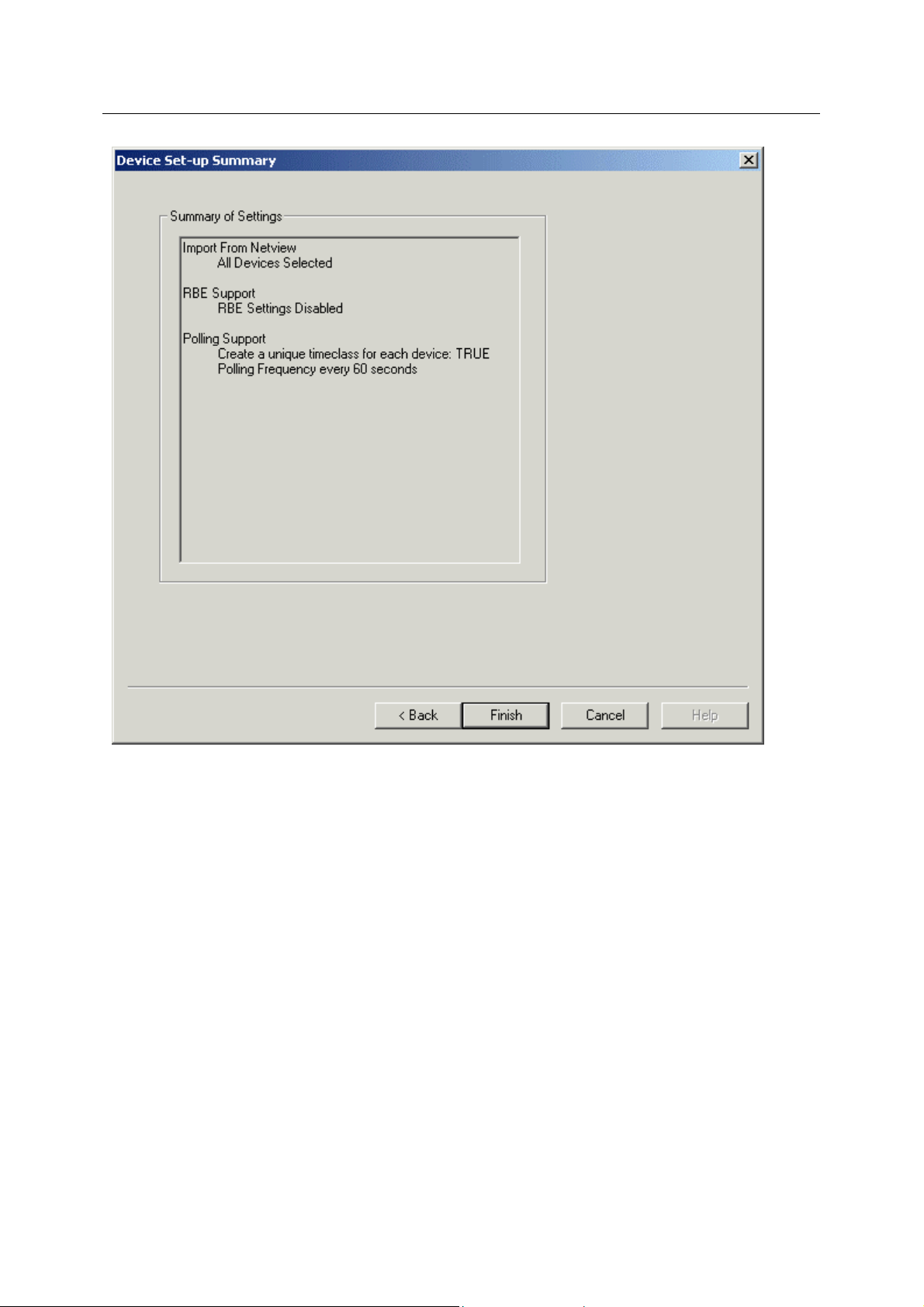
4.4 Device Setup Summary
This is the final dialog of the 'Device Set-up' wizard. It enables the user to view a summary of the
configuration prior to accepting it. Should any changes be required, the user may navigate back to the
relevant dialog to make the necessary changes prior to clicking the 'Finish' button.
- 23 -
Page 27

Reference Guide
D301509X412
April 2012
NW3000 Setup
This is the final dialog of the 'Device Set-up' wizard. It enables the user to view a summary of the
configuration prior to accepting it. Should any changes be required, the user may navigate back to the
relevant dialog to make the necessary changes prior to clicking the 'Finish' button.
- 24 -
Page 28
Reference Guide
D301509X412
April 2012
NW3000 Setup
4.4.1 Device Setup Finish Button
The DataBase Builder will be started, followed by the Poll List Builder. Any new application signals not
yet in the database will be added, new timeclasses will be created and new poll lists will be created
for data collection.
- 25 -
Page 29

Reference Guide
D301509X412
April 2012
5 Index
1
A
ACCOL Names ................................................ 18
Acknowledge Return........................................ 11
Active Polling.............................................. 13, 14
Active Polling Frequency.................................. 14
Advanced Button................................................ 5
All Devices........................................................ 20
ALM.................................................................. 18
Analog Alarms.................................................. 15
Auto Resolve.................................................... 18
Automatically Start OpenBSI.............................. 7
Automatically Stop OpenBSI.............................. 7
B
Background Polling Dialog............................... 13
Background Polling Frequency........................ 14
C
Cancel Button..................................................... 5
Cancel Button on Wizard Dialog........................ 7
Case sensitive RTU names.............................. 16
Consecutive failures allowed ........................... 10
Control Wave ................................................... 18
Create............................................................... 23
Critical .............................................................. 11
D
Device .............................................................. 23
Device Health Checking Dialog ......................... 9
Device RBE Support Dialog............................. 21
Device Set.......................................................... 5
Device Set-up Button......................................... 5
Device Setup Finish Button.............................. 25
Device Setup Summary Dialog........................ 24
Device Setup Wizard........................................ 19
Devices per health check................................. 10
E
Enable RBE Data Collection............................ 22
Enable Remote Alarm Support........................ 11
Event................................................................ 12
F
Frequency ........................................................ 24
NW3000 Setup
H
Help Button.........................................................8
Help Menu...........................................................5
I
Import From Netview Dialog.............................20
Include RBE Signals.........................................14
Include System Signals ....................................16
L
Look ..................................................................18
M
Main Dialog.........................................................4
Maximum Interval..............................................15
Maximum number...............................................9
Maximum total number .......................................8
Message Buffers Dialog......................................8
N
Name ................................................................18
Network 3000 Setup ...........................................4
Network Definition File........................................7
Non-Critical.......................................................12
Normal Reports.................................................11
Number.........................................................7, 10
NW3000 Analogs..............................................13
NW3000 Digitals...............................................14
NW3000 Setup Overview ...................................4
NW3000 Strings................................................14
O
Offset ................................................................15
OpenBSI AutoStart Dialog..................................6
Operator Guide.................................................12
P
Polling.........................................................23, 24
Polling Support..................................................23
R
RBE Data Collection.........................................13
RBE Support Dialog..........................................12
Remote Alarm Support Dialog..........................10
Requests.............................................................8
Requests per device...........................................9
- 26 -
Page 30

Reference Guide
D301509X412
April 2012
NW3000 Setup
Retry OpenBSI start........................................... 7
Retry OpenBSI start-up...................................... 7
S
Scan Rate......................................................... 22
Scan Slice ........................................................ 22
Seconds between device health checks.......... 10
Seconds between subsequent start attempts.... 7
Selected Devices ............................................. 22
Shot Poll........................................................... 15
Signal Import Dialog......................................... 15
Single Device................................................... 21
Start OpenBSI When OpenEnterprise Starts..... 7
Starting............................................................... 4
Stop OpenBSI When OpenEnterprise Stops..... 7
StopXmit........................................................... 22
Support Dialog..................................................23
System Set..........................................................5
System Set-up Button.........................................5
System Setup Finish Button .............................19
System Setup Summary Dialog........................18
System Setup Wizard .........................................6
T
Timeout.............................................................22
Times ..................................................................7
U
Unique Timeclass .............................................23
Use Settings......................................................21
Use Settings Here.............................................23
Use variable extension wizard..........................18
- 27 -
Page 31

Page 32

Reference Guide
D301509X412
April 2012
DISCLAIMER
Bristol, Inc., Bristol Babcock Ltd, Bristol Canada, BBI SA de CV and the Flow Computer Division , are wholly owned subsidiaries of Emerson Electric Co. doing business
as Remote Automation Solutions (“RAS”), a division of Emerson Process Management. ROC, FloBoss, ROCLINK, Bristol, Bristol Babcock, ControlWave, TeleFlow and
Helicoid are trademarks of RAS. AMS, PlantWeb and the PlantWeb logo are marks of Emerson Electric Co. The Emerson logo is a trademark and service mark of the
Emerson Electric Co. All other marks are property of their respective owners.
The contents of this publication are presented for informational purposes only. While every effort has been made to ensure informational accuracy, they are not to be
construed as warranties or guarantees, express or implied, regarding the products or services described herein or their use or applicability. RAS reserves the right to
modify or improve the designs or specifications of such products at any time without notice. All sales are governed by RAS’ terms and conditions which are available upon
request. RAS does not assume responsibility for the selection, use or maintenance of any product. Responsibility for proper selection, us e and maint en ance of any RAS
product remains solely with the purchaser and end-user.
Engineered and supported by:
Remote Automation Solutions,
Blackpole Road, Worcester, WR3 8YB, UK
Registered office: Meridian East, Leicester, LE19 1UX
Registered in England and Wales, Registration No. 00671801
VAT Reg No. GB 705 353 652
Emerson Process Management
Remote Automation Solutions
1100 Buckingham St
Watertown, CT 06795
T 1 (860) 945 2200
F 1 (860) 945 2278
www.EmersonProcess.com/Remote
binfo@EmersonProcess.com
© 2001-2012 Remote Automation Solutions, division of Emerson Process Management. All rights
reserved.
Emerson Process Management
Remote Automation Solutions
Blackpole Road
Worcester, WR3 8YB
T 44 (0) 1905 856848
F 44 (0) 1905 856930
www.EmersonProcess.com/Remote
oedsupport@EmersonProcess.com
 Loading...