

Page 1

Part Number D301597X012
Form A6267
May 2017
DS800 Development Suite Quick Start Guide
for the FloBoss
™
107
Remote Automation Solutions
Page 2

DS800 Development Suite Quick Start Guide (FB107)
Revision Tracking Sheet
May 2017
This manual may be revised periodically to incorporate new or updated information. The revision date of each
page appears at the bottom of the page opposite the page number. A change in revision date to any page also
changes the date of the manual that appears on the front cover. Listed below is the revision date of each page
(if applicable):
Page Revision
Initial issue Jan-09
Cover, back of cover
page, page 1, page
63, and back cover (all
pages re-dated)
May 2017
ii Revised May-2017
Page 3

Introduction
DS800 Development Suite Quick Start Guide (FB107)
The DS800 Development Suite software (“DS800”) is an integrated
development environment that allows you to build IEC 61131-3
compliant programs. You install DS800 on your PC and use the
software to develop programs and download those programs (using a
serial connection) to the FloBoss 107 (“FB107”).
Note: For further technical information, refer to the product data sheet
DS800 Development Suite Software (part D301160X012).
This Quick Start Guide provides both a high-level overview and the
detailed steps you need to install and configure the DS800 software on
your PC. It also provides a very simple example of building an IEC
61131-3 compliant program.
Note: FB107 firmware version 1.4 added user program slot 7. This slot
uses the same memory space as the DS800 kernel, which is not
included in the program and must be downloaded into the
FB107. Consequently, you cannot have the DS800 kernel
installed and use program slot 7 for a separate user program at
the same time.
The installation process requires you to:
1. Verify versions of ROCLINK 800 and the FB107 firmware.
2. Install the DS800 Runtime License on the FB107.
Note: Perform software installations using the LOI point on the
FB107.
3. Install the DS800 Runtime kernel on the FB107.
4. Set CPU and I/O scanning speed on the FB107.
5. Define a comm port on the FB107 for the DS800 communications.
6. Create a configuration file (which the DS800 software uses).
7. Save the FB107 Flash configuration.
8. Install the DS800 Workbench software (DS800 Development Suite
and LicenseManager) on your PC.
9. Verify the successful installation.
Note: To understand all the steps and system requirements, we suggest
that you read through this entire guide before you begin the
installation and configuration process.
After you have successfully installed the software, review Creating a
Sample Workbench Project for a detailed example of building a simple
IEC 61131-3 program.
Revised May 2017 1
Page 4

DS800 Development Suite Quick Start Guide (FB107)
1. Verify Versions of ROCLINK 800 and FB107
When installed on an FB107, the DS800 software requires:
Version 1.80 (or greater) of ROCLINK 800.
Version 1.20 (or greater) of FB107 application firmware.
To verify the versions:
1. Start ROCLINK 800.
2. Click Help on the ROCLINK 800 tool bar and click About
ROCLINK 800 from the drop-down menu. The About ROCLINK
800 screen displays.
Software Version
3. Verify that the version of ROCLINK 800 is 1.80 or greater.
Note: If the version is not at least 1.80, contact your Remote
Automation Solutions representative to upgrade ROCLINK
800.
4. Click OK. The FB107 graphic displays.
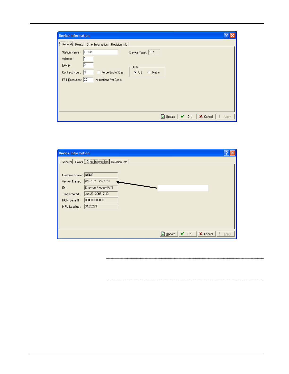
5. Click ROC on the ROCLINK 800 toolbar and click Information on
the drop-down menu. The Device Information screen displays.
2 Revised May 2017
Page 5
DS800 Development Suite Quick Start Guide (FB107)
6. Select the Other Information tab. The Other Information screen
displays.
Firmware Version
7. Verify that the firmware version for your FB107 is 1.20 or greater.
Note: If the version is not at least 1.20, contact your Remote
Automation Solutions representative to upgrade the
firmware.
8. Click OK to close the Device Information screen, but do not exit
ROCLINK 800. Proceed to Install the DS800 Runtime License.
2. Install the DS800 Runtime License
The DS800 software requires you to install a runtime license on the
FB107. If you do not load this runtime license, you cannot download
DS800 “projects” (applications) from your PC to the FB107. Remote
Revised May 2017 3
Page 6

DS800 Development Suite Quick Start Guide (FB107)
Automation Solutions distributes the runtime license using a securityenhanced USB drive (or “key”) with a purple label:
To install the runtime license:
1. Click Utilities on the ROCLINK 800 menu bar, highlight License
Key Administrator on the drop-down menu, and click Transfer
between DEVICE and KEY. The Transfer Licenses Between a
Device and a Key screen displays.
Connect to KEY
2. Insert the security-enhanced USB drive in a USB port on your PC
and click Connect to KEY. This refreshes the screen and shows the
licenses on the USB key.
4 Revised May 2017
Page 7

DS800 Development Suite Quick Start Guide (FB107)
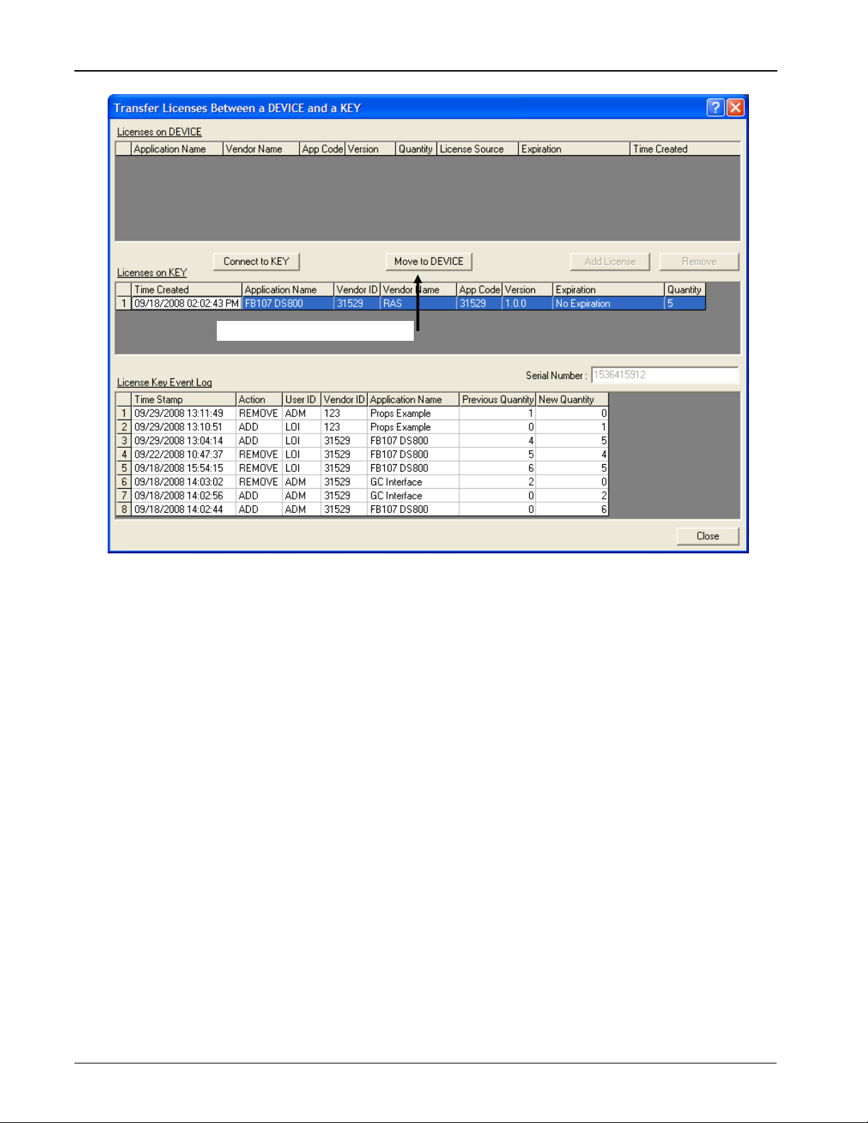
Licenses on USB key
3. Click the line for the licenses on the key to highlight it. Note that the
label on the Move to KEY button changes to Move to DEVICE.
Revised May 2017 5
Page 8
DS800 Development Suite Quick Start Guide (FB107)
Label on button changes
4. Click Move to DEVICE. ROCLINK 800 moves one license from
the key to the FB107.
6 Revised May 2017
Page 9

DS800 Development Suite Quick Start Guide (FB107)
DS800 license added to FB107
Total number of licenses decreases
5. Click Close to exit the screen and redisplay the FB107 graphic. Do
not exit ROCLINK 800. Proceed to Install the DS800 Runtime
Kernel.
Note: For more information on FB107 software licenses, refer to
the ROCLINK™ 800 Configuration Software User Manual
™
(for FloBoss
107), Form A6217.
3. Install the DS800 Runtime Kernel
The DS800 kernel is the “connecting engine” which runs inside the
FB107 and interprets and executes DS800 programs. The kernel is not a
standard FB107 component; you must install it. Remote Automation
Solutions distributes the kernel on a CD-ROM.
To install the DS800 kernel:
1. Insert the CD-ROM.
2. Click Configure on the ROCLINK 800 tool bar, highlight Control
on the drop-down menu, and click DS800. The DS800
Administrator screen displays.
Revised May 2017 7
Page 10
DS800 Development Suite Quick Start Guide (FB107)
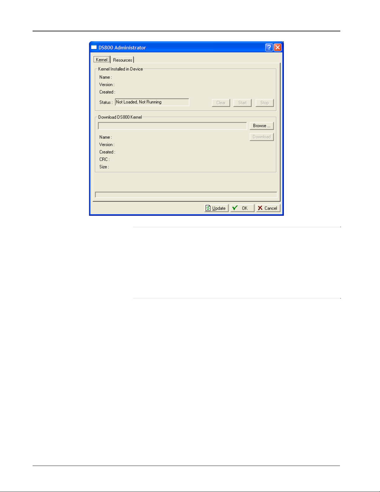
Note: This screen has two tabs: Kernel and Resources. Use the
Kernel tab to load the DS800 kernel and view associated
information. Use the Resource tab to load binary DS800
programs without the PC-based Workbench software. The
upper frame on the Kernel tab (Kernel Installed in Device)
provides information on the kernel currently installed; the
lower frame identifies and provides specific information on
kernels you may want to download to the FB107.
3. Review the upper frame on the Kernel tab. If the kernel has not been
installed in the FB107, the Status field displays the message Not
Loaded, Not Running.
4. Click Browse in the lower frame. A Select DS800 Kernel File
dialog displays. Remote Automation Solutions distributes the
DS800 kernel as a file with a .bin extension (D:\CD
Name\Folder\Kernel\DS800_FB107_1_00.bin). Browse to the
location on the CD where this file is stored and click Open. A
populated version of the DS800 Administrator screen displays.
8 Revised May 2017
Page 11
DS800 Development Suite Quick Start Guide (FB107)
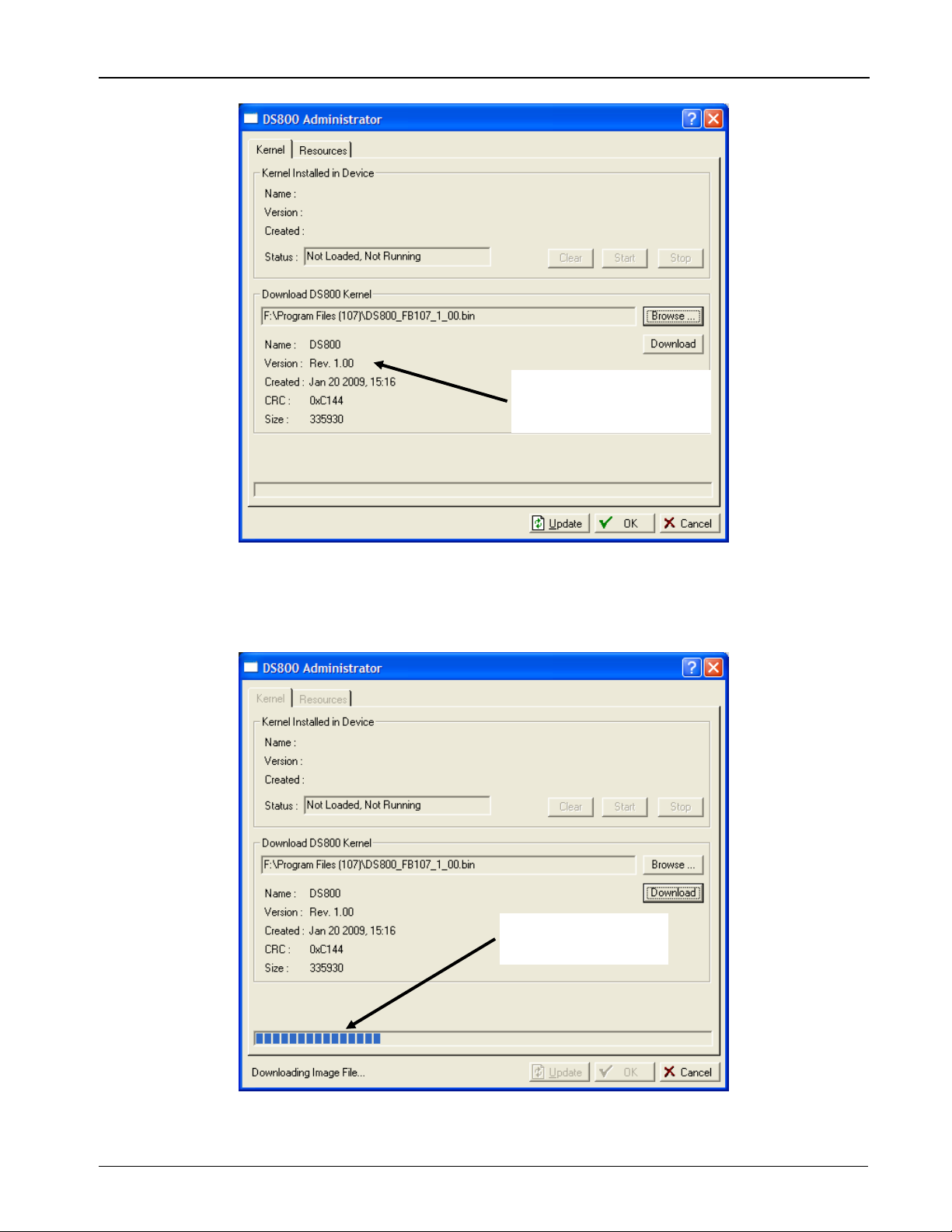
ROCLINK 800 provides
information on the
selected file
5. Click Download. ROCLINK 800 displays an authorization dialog
box. Click Yes to begin the download. As the download proceeds,
ROCLINK 800 displays a progress bar at the bottom of the screen.
Download progress
indicator
When the download completes, ROCLINK 800 displays a
notification dialog.
Revised May 2017 9
Page 12
DS800 Development Suite Quick Start Guide (FB107)
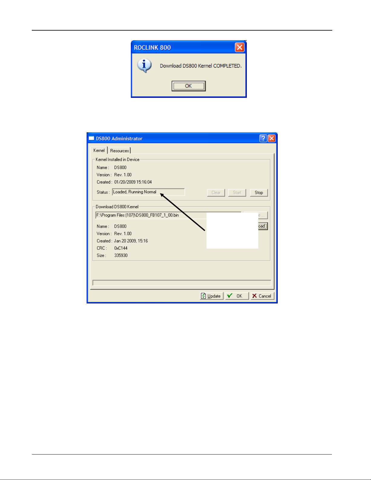
6. Click OK to complete the download. The Status message changes to
indicate that the kernel is installed and running.
The kernel is
successfully
installed and
running
7. Click OK to exit the DS800 Administrator screen and display the
FB107 graphic. Do not exit ROCLINK 800. Proceed to Set CPU
Clock and I/O Scanning Speed.
4. Set CPU Clock and I/O Scanning Speed
Set the CPU and I/O scanning speed on the FB107 to ensure the fastest
possible Workbench installation.
To set the CPU and I/O scanning speed:
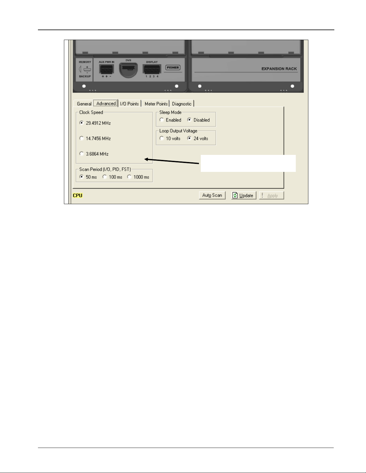
1. Click the Advanced tab on the folders immediately below the
FB107 graphic. The Advanced tab displays:
10 Revised May 2017
Page 13
DS800 Development Suite Quick Start Guide (FB107)
Clock Speed and Scan Period
frames
2. Verify that the value in the Clock Speed frame is set to 29.4912
MHz.
3. Verify that the value in the Scan Period frame is set to 50 ms.
4. Click Apply if you have changed any values on this screen. Do not
exit ROCLINK 800. Proceed to Set Comm Port Owner.
5. Set Comm Port Owner
Defining an application (in this case, DS800) as a communications port
owner enables the application to communicate directly with the FB107.
To set the comm port owner:
1. Click ROC > Comm Ports on the ROCLINK 800 menu bar. The
Comm Port screen displays.
Revised May 2017 11
Page 14

DS800 Development Suite Quick Start Guide (FB107)
Port Owner frame
2. Click to the right of the Comm Ports field to display all available
comm ports.
3. Click Comm2. The DS800 option in the Port Owner frame
activates.
12 Revised May 2017
Page 15
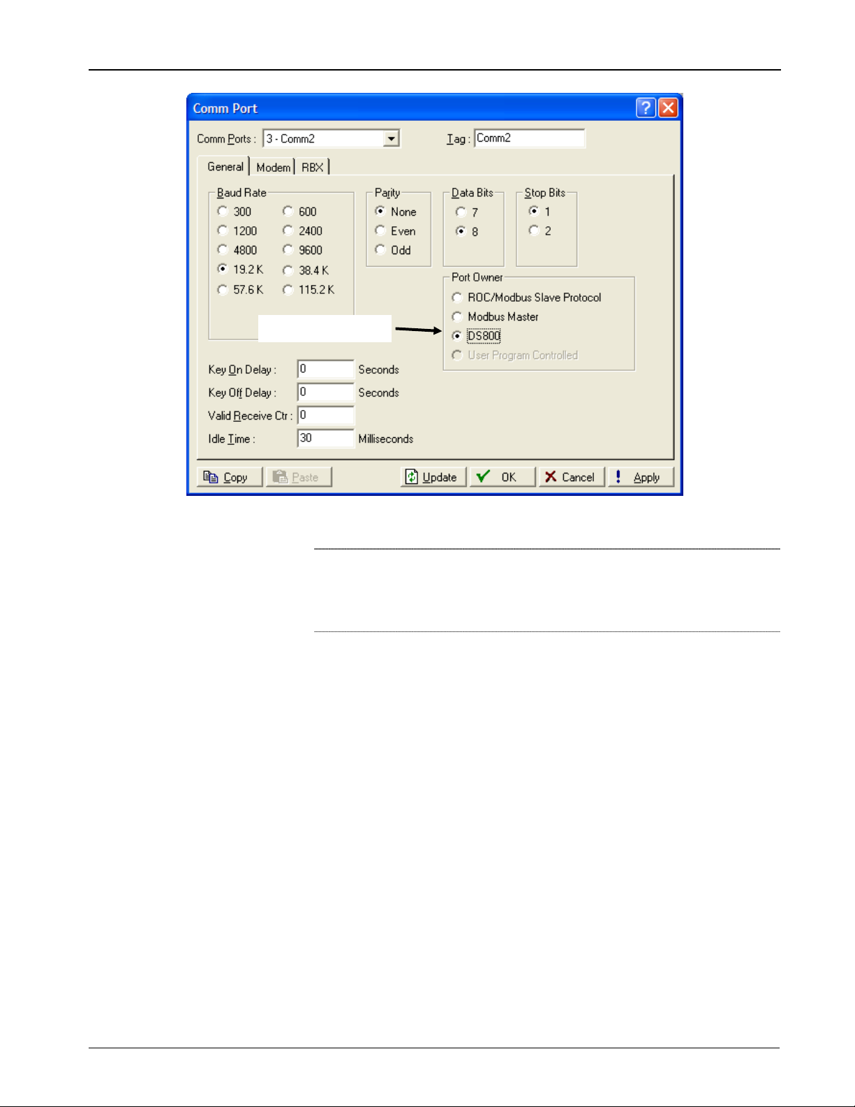
Port Owner frame
DS800 Development Suite Quick Start Guide (FB107)
4. Select DS800.
Note: ROCLINK 800 automatically changes the value in the Baud
Rate frame to 19.2 K to match the DS800 option you have
selected. 19.2K is also the maximum baud rate DS800
supports.
5. Click Apply to save your changes, and then click OK to display the
FB107 graphic. Proceed to Create Configuration File.
6. Create Configuration File
Creating a configuration (.800) file preserves the I/O configuration you
have defined on your FB107. The DS800 Workbench software uses this
configuration file (and its defined point types) to correctly map
information you define in the Workbench back to your FB107.
To create a configuration file:
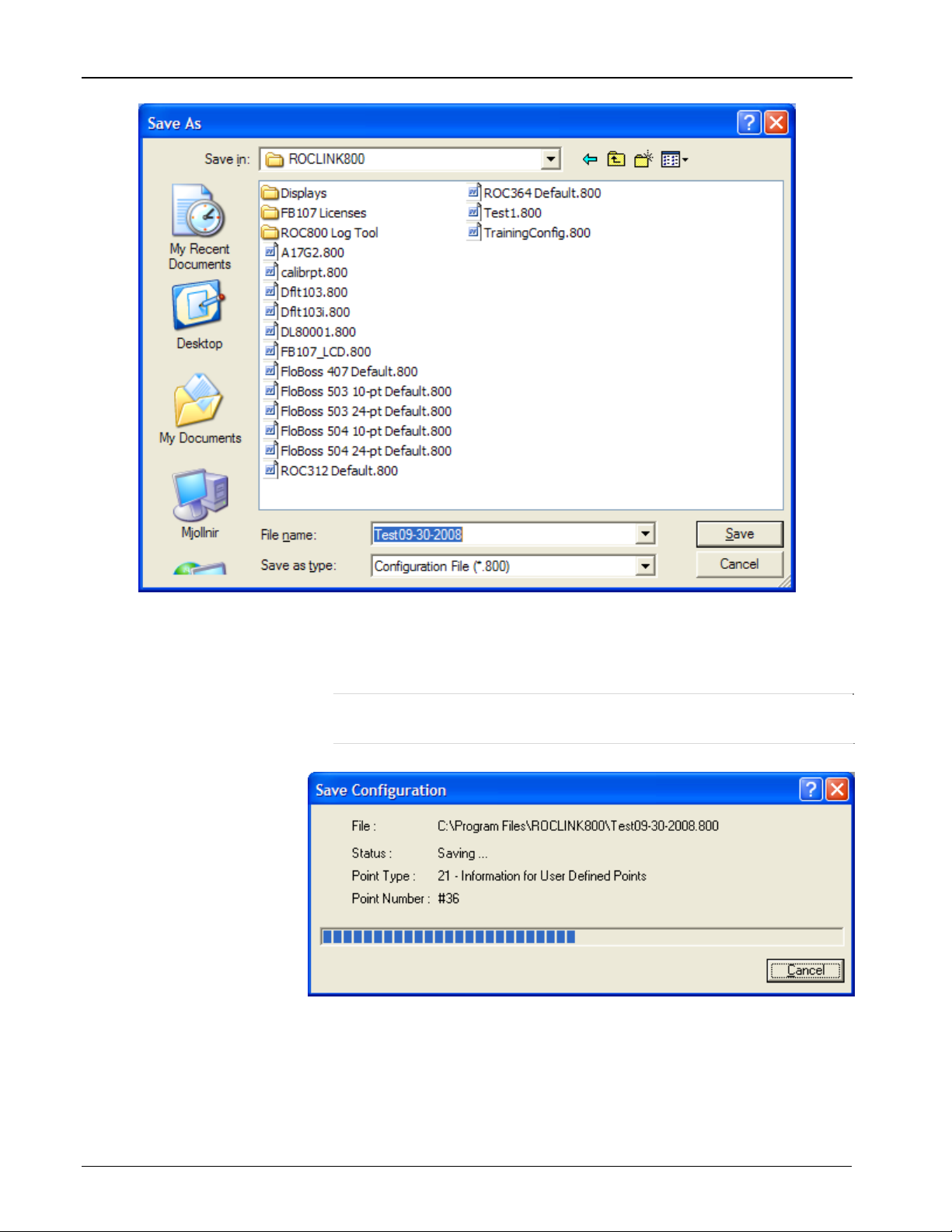
1. Click File > Save Configuration on the ROCLINK 800 menu bar.
A Save As dialog screen displays.
Revised May 2017 13
Page 16
DS800 Development Suite Quick Start Guide (FB107)
2. Complete the File name field with a meaningful file name (here,
Test09-30-2008). Click Save. ROCLINK 800 displays a dialog box
that shows the progress of the save.
Note: By default, ROCLINK 800 places all configuration files in
the /ROCLINK800 folder on your PC.
A change in the Status message indicates when the process
finishes.
14 Revised May 2017
Page 17

DS800 Development Suite Quick Start Guide (FB107)
3. Click Close to complete the process. The Save Configuration dialog
box closes and displays the FB107 graphic. Proceed to Save Flash
Configuration.
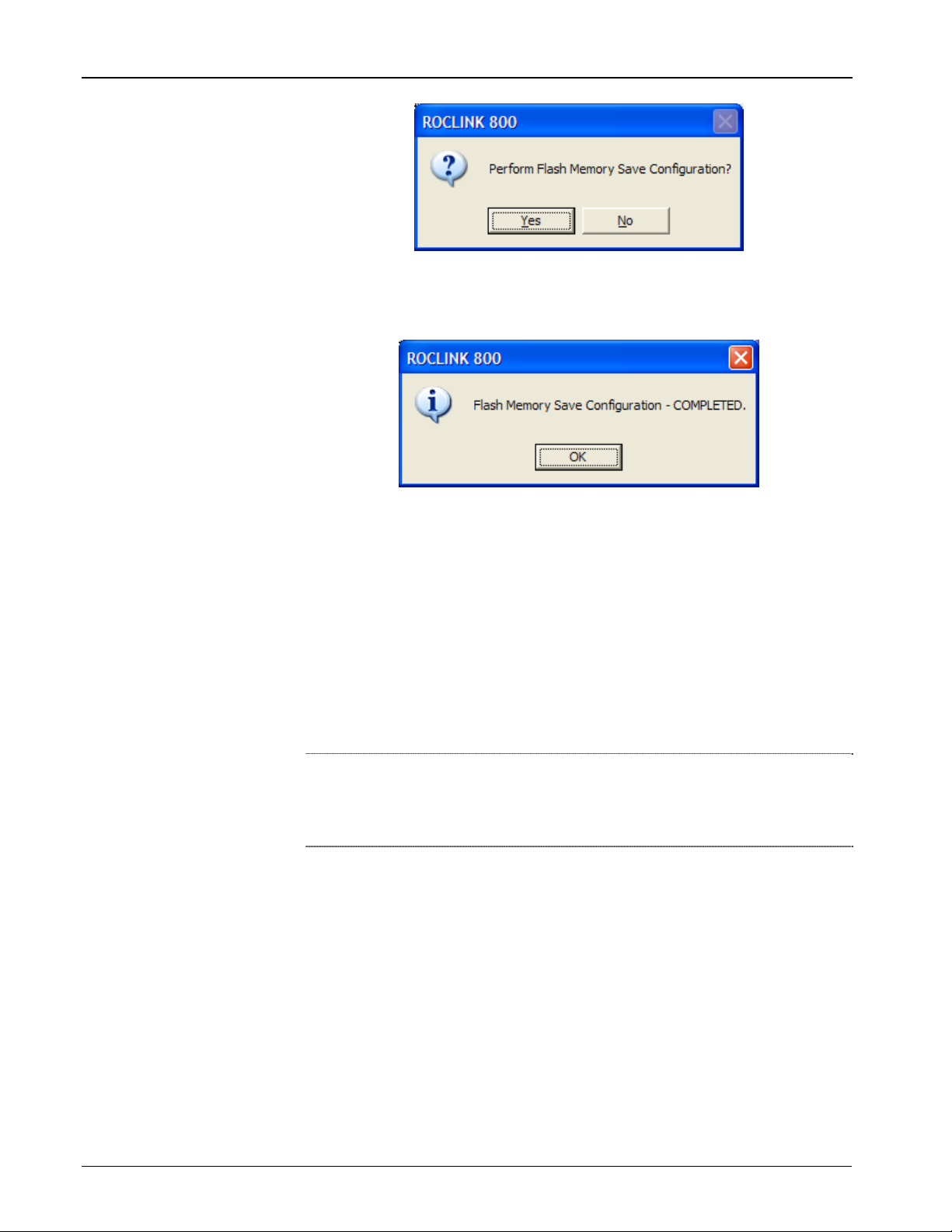
7. Save Flash Configuration
Save completed
Saving the Flash configuration in your FB107 is a precautionary step.
1. Select ROC > Flags. The Flags screen displays.
2. Click Save Configuration in the Flash Memory frame. ROCLINK
800 displays a confirmation dialog:
Revised May 2017 15
Page 18
DS800 Development Suite Quick Start Guide (FB107)
3. Click Yes. ROCLINK 800 saves the configuration and displays a
dialog box when it finishes.
4. Click OK to close this dialog box. The Flags screen displays. Click
OK to display the FB107 graphic. Proceed to Install the DS800
Workbench Software.
8. Install the DS800 Workbench Software
The DS800 Workbench software provides the development environment
you use to create DS800 “projects” (IEC 61131-3 compliant programs)
which you consequently download to the FB107.
Note: For more information on creating DS800 projects, refer either to
Create a Sample Workbench Project in this document or to the
DS800 Development Suite Software User Manual (Form
A6126).
Remote Automation Solutions delivers the DS800 Workbench software
on a CD-ROM. Your PC must have the following minimum
requirements:
Pentium-class processor (233 MHz or greater recommended).
CD-ROM drive.
Windows 2000 (Service Pack 2), XP, or Vista.
Serial port.
Administrative privileges for the PC on which the software is to be
installed.
16 Revised May 2017
Page 19

DS800 Development Suite Quick Start Guide (FB107)
Caution
A Sentinel USB license key provides access to all the DS800 Workbench
features. Do not insert the Sentinel USB license key in any USB port on
your PC until directed to do so. Using the key before the Workbench is
completely installed may cause unpredictable results.
To install the software:
1. Place the CD-ROM into your PC’s CD drive. The Product Installer
wizard starts automatically.
Note: If you have Autorun enabled on your computer, the Product
Installer wizard starts automatically. If you have disabled
Autorun, use this procedure to start the wizard:
a. Click Start > Run. The Run dialog box displays.
b. Click Browse, navigate to the folder on the CD-ROM
containing the Workbench software, and select the
Setup.exe file in that folder. The Run dialog box
displays.
c. Click OK. The Product Installer wizard screen
displays.
2. Click Next. A software license agreement displays.
Revised May 2017 17
Page 20

DS800 Development Suite Quick Start Guide (FB107)
3. Read the entire DS800 software license agreement. If you agree
to the terms of the license, select I accept the terms of the
license agreement and click Next. A Select Features screen
displays.
4. Use this screen to select the two DS800 features you must
install:
Development Suite 800
Also known as the “Workbench,” this is the development
18 Revised May 2017
Page 21

DS800 Development Suite Quick Start Guide (FB107)
environment you use to create, view, and download custom
control applications to the FB107.
LicenseManager
Supports the USB Sentinel license key which is required to
access all Workbench features. You also use this utility to
transfer licenses and update existing license keys.
Note: The wizard selects these two features as defaults.
5. Click Next. A review screen displays.
6. Review the options you have selected for installation and click
Next. The DS800 initial (or “splash”) screen displays.
Revised May 2017 19
Page 22

DS800 Development Suite Quick Start Guide (FB107)
Note: Once you begin the DS800 installation process, you cannot stop
it until it completes.
7. Click Install. The wizard prompts you to select the location for
the installed software.
8. Click Next to accept the default location or click Browse to
select another location.
20 Revised May 2017
Page 23

DS800 Development Suite Quick Start Guide (FB107)
Note: If you have inserted the Sentinel USB license key in your
computer, remove it BEFORE you click Next.
9. The wizard begins installing the first component (the DS800
Workbench).
10. When the installation of the Workbench completes, the wizard
prompts you to include an icon on your desktop.
Revised May 2017 21
Page 24

DS800 Development Suite Quick Start Guide (FB107)
11. Click either Yes or No to continue. The wizard begins installing
the second component (the LicenseManager).
12. When the installation of the LicenseManager completes, the
wizard prompts you to include an icon on your desktop.
13. Click either Yes or No to continue. The wizard prompts you to
restart your computer.
22 Revised May 2017
Page 25

DS800 Development Suite Quick Start Guide (FB107)
Note: Until you restart your computer, do not start the DS800
application.
14. Proceed to Verify the DS800 Workbench Installation.
9. Verify the DS800 Workbench Installation
Remote Automation Solutions distributes the DS800 Workbench license
on a Sentinel USB key with a blue label:
Note: During this verification process, you are instructed to insert this
Sentinel USB license key in your computer. Do not insert the
Sentinel USB license key into a USB port on your computer
until directed to do so.
To start Workbench:
1. Click Start > Programs > Emerson Process Management >
DS800 2.1 (select the DS800 2.1 application, not the folder). A
splash screen (indicating the version number and build date for the
software) displays briefly, and then closes to display the DS800
screen.
Revised May 2017 23
Page 26

DS800 Development Suite Quick Start Guide (FB107)
Red “banner” at bottom of
screen indicates Technician
(read-only) mode
The red banner at the bottom of the DS800 screen indicates that the
software successfully installed but was unable to find the license
key.
2. Exit the application (select File > Exit on the DS800 menu bar).
3. Insert the Sentinel USB license key into a USB port on your
computer. Windows automatically recognizes the USB device and
displays a recognition message in the System Tray.
24 Revised May 2017
Page 27

DS800 Development Suite Quick Start Guide (FB107)
Note: If Windows does not automatically recognize the USB
device, proceed to the Troubleshooting section of this
document.
4. Click Start > Programs > Emerson Process Management >
DS800 2.1 (again, select the application and not the folder). The
splash screen displays, followed by the DS800 screen.
No “banner” at bottom of
screen indicates DS800 has
recognized the license key
Note: This version of the DS800 screen does not have a red banner
across the bottom of the screen. This means that DS800
detected the license key and changed the Workbench
functionality accordingly. If the DS800 still has a red banner,
proceed to the Troubleshooting portion of this document.
5. You can begin to develop DS800 projects. Refer to Creating a
Sample Workbench Project in this guide.
Troubleshooting the Installation
The DS800 Development Suite software and the USB Sentinel® license
key use Sentinel Protection from SafeNet® Incorporated. Other software
vendors today use the same technology, so if Windows does not
recognize an attached USB license key, it’s possible that conflicting
versions of the SafeNet Sentinel software are installed on your
computer.
To resolve this conflict, you must uninstall all versions of the Sentinel
driver from your computer and install the latest version. The updated
Revised May 2017 25
Page 28

DS800 Development Suite Quick Start Guide (FB107)
driver allows Windows to recognize the USB license key and does not
adversely affect any other programs which use the SafeNet Sentinel
driver.
To uninstall prior versions of the Sentinel driver:
Note: Before you update any drivers, close all applications (such as
DS800 Development Suite) which may require a USB license
key.
1. Open the Windows Control Panel (click Start > Settings > Control
Panel).
2. Double-click Add or Remove Programs. Windows builds a list of
all programs currently installed on your computer.
Click here to scroll
down the program list
3. Scroll down the program list until you find software programs which
begin with the word “Sentinel.”
26 Revised May 2017
Page 29

DS800 Development Suite Quick Start Guide (FB107)
Sentinel program
4. Click the program label. Windows opens a program-specific dialog
box you use to change or remove this program.
Click to remove the
program
5. Click Remove. Windows displays a verification dialog box asking
you to verify the removal request.
Revised May 2017 27
Page 30

DS800 Development Suite Quick Start Guide (FB107)
6. Click Yes to continue. Windows displays a number of dialog boxes
as it removes the program. If necessary, the last dialog box reminds
you to restart your computer.
Note: If you have several programs to remove, remove all
programs before you restart your computer.
7. Repeat steps 3-6 for any other Sentinel drivers. When you have
uninstalled all previous versions of Sentinel drivers, you can install
the most current Sentinel driver.
To install the most current version of the Sentinel driver:
1. Place the CD-ROM you used to install the DS800 software in your
computer’s CD drive.
2. Click Start > Run. The Run dialog box displays.
3. Click Browse. Remote Automation Solutions placed the 7.5.0
Sentinel driver in the \Sentinel folder on the CD-ROM. Select the
Sentinel System Driver Installer 7.5.0.exe file. The Run dialog box
displays the selected file.
4. Click OK. The InstallShield wizard displays.
28 Revised May 2017
Page 31

DS800 Development Suite Quick Start Guide (FB107)
Note: If you have not removed all prior versions of the Sentinel
Protection Installer, the wizard detects those versions and
displays this screen to ensure the upgrade of all previous
versions.
5. Click Upgrade. The wizard displays the installation splash screen.
6. Click Next. A license agreement screen displays.
Revised May 2017 29
Page 32

DS800 Development Suite Quick Start Guide (FB107)
7. Select I accept the terms in the license agreement and click Next.
The wizard displays a screen for the type of setup.
8. Select Complete and click Next. The wizard displays a screen used
to start the actual installation.
30 Revised May 2017
Page 33

DS800 Development Suite Quick Start Guide (FB107)
9. Click Install. The wizard displays a security settings screen.
10. The DS800 does not include the ability to access Sentinel license
keys from a remote machine. If you are aware of any installed
software on your computer which requires this functionality, click
Yes. Otherwise, click No. The wizard begins installing the software
based on your selections.
Revised May 2017 31
Page 34

DS800 Development Suite Quick Start Guide (FB107)
11. As the installation proceeds, the wizard displays a progress
indicator. When the installation finishes, the wizard displays a
completion screen.
12. Click Finish to exit the installation wizard.
32 Revised May 2017
Page 35

DS800 Development Suite Quick Start Guide (FB107)
Creating a Sample Workbench Project
The DS800 Workbench software provides the development environment
you use to create DS800 “projects” (IEC 61131-3 compliant programs)
which you consequently download to the FB107.
The functionality in the DS800 Workbench varies depending on the
license key installed. With no license key installed, Workbench runs in
Technician mode.
Technician mode can be considered “read-only” mode. You cannot
create a new project or edit previously created projects. You can view
existing projects and download them into the FB107. When the software
is running in Technician mode, a red banner appears across the bottom
of the window reading “Technician version for DS800 users only.”
Two license keys—PR2 and PRD—allow full use of Workbench.
The PR2 license key enables you to use Workbench to create and edit
an unlimited number of projects. However, PR2-created projects can
only contain a single configuration (hardware unit), a single resource,
and are limited to 128 points of I/O.
The PRD license key also enables you to use Workbench to create and
edit an unlimited number of projects. However, PRD-created projects
can contain an unlimited number of configurations (hardware units),
define up to 4 resources per unit, and have an unlimited number of I/O
points. You can distribute PRD-created projects across multiple devices.
With the FB107, you can define only a single resource. Although you
can use a PRD license to create projects for the FB107, the PRD is
typically used in conjunction with the ROC800-Series devices.
A trial version of Workbench is also available. The trial version has the
same features as a PRD license, but it operates for only 30 days. After
30 days the trial expires and you must uninstall the software. Any
projects you may have created with the trial version require a copy of
Workbench with a PR2 or PRD license key. Contact your local Remote
Automation Solutions representative to receive a copy of the trial
version of Workbench.
Hardware Units
Supported
Technician
PR2
PRD
Trial
Unlimited 4 Unlimited
1 1 128
Unlimited 4 Unlimited
Unlimited 4 Unlimited Expires in 30 days
Resources per
Hardware
I/O Points
Notes
Cannot create or
edit projects
Revised May 2017 33
Page 36

DS800 Development Suite Quick Start Guide (FB107)
Technician mode is basically a “read-only” mode. You cannot create
new projects or edit previously created projects, but you can view
existing projects and download projects.
Getting Started with DS800
The DS800 workbench is designed to help you build process control
applications. You can distribute these applications across several
platforms or enable the applications to communicate with each other
through networks. A DS800 project shows the distribution and links
between each PLC loop, which the DS800 kernel (or “virtual machine”)
executes on each platform.
Using the function block diagram language, this section details the steps
required to build a sample project (creating an incrementing counter in a
soft point parameter) and familiarizes you with the views, buttons, and
vocabulary of DS800.
The following steps are involved:
1. Creating a New Project
2. Importing a Device Configuration
3. Adding Variables to the Dictionary
4. Creating a Program to the Resource
5. Compiling the Program
6. Compiling the Project
7. Downloading the Project
8. Debugging the Project
9. Verifying the Program in ROCLINK 800
1. Creating a New Project
To create a new DS800 project:
1. Click the DS800 2.1 icon on your desktop. The DS800 workspace
screen displays.
Note: If you did not create a desktop icon for this application, you
can also click Start > Programs > Emerson Process
Management > DS800 2.1.
2. Click the New Project icon ( ) on the DS800 workspace toolbar.
A New project dialog box displays.
34 Revised May 2017
Page 37

DS800 Development Suite Quick Start Guide (FB107)
Note: By default, DS800 places project files in the folder
C:\Program Files \ Emerson Process Management\ Projects\
DS800 2.1. If you want your project files in another location,
click Browse to select that location.
Views
3. Enter SampleProject in the Name field.
4. Click in the Template field to open a drop-down menu. Select
SingleFB107.
Note: By default, DS800 creates a template for a single ROC800.
This template tells the application how to structure data.
SingleFB107 is the template that works with the FB107.
5. Click OK. The DS800 Resource view screen displays.
DS800
Revised May 2017 35
Page 38

DS800 Development Suite Quick Start Guide (FB107)
r
Use the icons on the DS800 toolbar and the Views toolbar to work
with the project data. Small descriptive tags appear as you move the
cursor over each toolbar icon.
6. Click the hardware architecture icon ( ) on the Views toolbar to
display the Hardware Architecture view.
Resource
Drive
Network
This screen shows your project in relationship to existing hardware.
Resource
Configuration
Target
A resource is composed of programs and corresponds
to a PLC loop. You compile a resource and then
download its code to configuration, where the DS800
kernel (“virtual machine”) executes it.
A hardware platform, linked to other hardware
platforms by a serial network. Use DS800’s Hardware
Architecture view to display configurations.
You attach a configuration to a specific target. A target
contains definitions about the hardware platform and
the virtual machine running on it.
Double-click the configuration’s title bar to display a
Configuration Properties screen, which has three tabs:
36 Revised May 2017
Page 39

Network
DS800 Development Suite Quick Start Guide (FB107)
General, which provides a title and any comments
for the configuration.
Hardware, which indicates the target device (such
as the FB107) for this configuration. This is the
first tab that displays.
Security, which sets a password security to
prevent unauthorized changes to the
configuration’s properties.
Specifying a target for a configuration affects the list of
functions and function blocks that you can call in your
programs, the list of I/O devices that you can use, and
the networks that you can connect to your
configuration.
In the hardware architecture view, you can see that
resources communicate via the ISARSI (Serial)
network. ISARSI is the standard driver Remote
Automation Solutions provides to communicate over a
serial protocol link. The Workbench debugger also
uses ISARSI to communicate with the resources
running on the configurations.
7. Double-click the horizontal (Network) line to open the network
configuration. A Network Properties screen displays.
Revised May 2017 37
Page 40

DS800 Development Suite Quick Start Guide (FB107)
8. Modify the values on this screen according to the serial port on the
PC you intend to use to connect to the device (here, the FB107).
Click OK to save any values.
9. Proceed to Importing a Device Configuration.
2. Importing a Device Configuration
The device configuration file contains device-specific information (such
as number of points, number of meters, and TLPs) the DS800
application needs to appropriate place data. (You created a configuration
file for the FB107 in Step 6 of the installation process.)
1. Right-click the configuration’s title bar. A menu displays.
38 Revised May 2017
Page 41

DS800 Development Suite Quick Start Guide (FB107)
2. Select Properties. The Configuration Properties screen displays.
Configuration
selector
3. Click the right-most browse button. A message box cautions you
that importing a configuration may reload the entire project.
4. Click Yes. The Select ROCLINK 800 Configuration File screen
displays.
Revised May 2017 39
Page 42

DS800 Development Suite Quick Start Guide (FB107)
Note: As a default, ROCLINK 800 stores configuration files in the
folder C:\Program Files\ROCLINK800. You may need to
browse to this folder to locate the configuration file you
want.
5. A dialog box displays that you use to select the configuration file to
import.
6. Select a file and click Open. The Configuration Properties screen
displays with the configuration you have selected.
7. Click OK to apply the configuration file to the project. Once the file
is loaded, DS800 displays the Resource view.
40 Revised May 2017
Page 43

DS800 Development Suite Quick Start Guide (FB107)
8. Proceed to Adding Variables to the Dictionary.
3. Adding Variables to the Dictionary
Once you have a configuration loaded, you can begin to define variables
in the DS800 dictionary. Variables associate TLPs in the FB107 with
DS800 content. To add variables:
1. Click the Dictionary icon ( ) on the toolbar to open the
Dictionary view.
Revised May 2017 41
Page 44

DS800 Development Suite Quick Start Guide (FB107)
Tree
2. In the tree to the left of the screen, click Variables > Resource1 >
Any Group > All variables. The panel in the right portion of the
screen changes to a grid format.
Double-click the blank row
3. Double-click the blank row to open a dialog box that helps you to
define the new variable.
42 Revised May 2017
Page 45

DS800 Development Suite Quick Start Guide (FB107)
A
4. Enter Total in the Name field, and select DINT (signed double
integer) in the Type file.
5. Click OK to add the variable. The Dictionary screen redisplays with
the variable added.
“Spreadsheet”
view button
dded variable
Revised May 2017 43
Page 46

DS800 Development Suite Quick Start Guide (FB107)
Note: Click the button in the upper right corner of the variable
view to display the variable table in an editable spreadsheet
format.
6. To define a second variable that is connected to a parameter in the
FB107, double-click the highlighted blank row to open the dialog
box.
7. Click the TLP browse button on the dialog box.
TLP browse
button
A TLP Browser screen displays.
8. Select 17 – Soft Point Parameters in the Point Type column. The
program completes the Logical Number and Parameter columns.
44 Revised May 2017
Page 47

DS800 Development Suite Quick Start Guide (FB107)
9. Leave SFP 1 as the value in the Logical Number column and select
Integer Flag in the Parameter column.
TLP value
Access type
10. Finally, select Write as the access type. Click OK. The variable
dialog box displays. Note that the values in several fields have
changed to correspond to your defined variable.
Revised May 2017 45
Page 48

DS800 Development Suite Quick Start Guide (FB107)
11. Click OK to add the variable to the dictionary.
12. Click the Save icon ( ) to save your changes to the dictionary.
13. Click the Link view icon ( ) to display the project’s link
architecture.
14. Proceed to Adding a Program to the Resource.
46 Revised May 2017
Page 49

DS800 Development Suite Quick Start Guide (FB107)
4. Adding a Program to the Resource
Using the Link Architecture view, you can see how the components of
your DS800 project fit together. The next step is to give the FB107
resource functionality by adding a program:
1. Right-click Programs in the Resource1 box. A menu displays.
2. Move the cursor over the Add Program option to display a menu of
programming languages.
3. Select FBD: Function Block Diagram. The Link Architecture view
displays, showing an unnamed FBD.
Revised May 2017 47
Page 50

DS800 Development Suite Quick Start Guide (FB107)
New FBD
4. Rename the UntitledFBD program as Counter.
5. Double-click the Counter program to open the DS800 Editor
program.
48 Revised May 2017
Page 51

Function block
tool (F3)
DS800 Development Suite Quick Start Guide (FB107)
6. Click the function block tool on the language toolbar (or press F3).
The cursor becomes a function block tool once you move it into the
editor grid.
7. Move the cursor in the middle of the editor screen and click. A
Select Blocks screen displays.
Revised May 2017 49
Page 52

DS800 Development Suite Quick Start Guide (FB107)
8. In the right-hand panel, select the second block option (Addition of
two or more integer or…) and click OK. The editor changes the
shape of the generic function block to an addition function block.
Note the two inputs on the left side of the block and one output
(which provides the sum) on the right side of the block.
50 Revised May 2017
Page 53

DS800 Development Suite Quick Start Guide (FB107)
9. Click the variable tool on the language toolbar (or press F2). The
cursor becomes a variable tool once you move it into the editor grid.
Variable tool (F2)
Revised May 2017 51
Page 54

DS800 Development Suite Quick Start Guide (FB107)
10. Move the variable tool close to one of the inputs on the left side of
the function block and click. The Select Variable dialog box
displays, which shows the variables currently defined for this
project.
Defined variables
11. Select the Total variable and click OK. The editor renames the
variable and, if the variable is close to the function block,
automatically links the variable and function block.
Renames and links
variable to function block
52 Revised May 2017
Page 55

DS800 Development Suite Quick Start Guide (FB107)
12. Select the variable tool again and click near the second input on the
function block to display the Select variable dialog box.
13. Enter 1 in the upper left-most field in the Select variable dialog box
and click OK.
Note: This value is not a variable, but is a constant value.
14. Select the variable tool a third time, but click near the output on the
function block. When the Select variable dialog box displays, select
the Total variable and click OK. At this point, the program should
look like this:
Draw Link tool
Note: If the editor has not automatically connected the variables to
the function block, select the Draw Link tool (F4) to connect
the variables. Alternately, you can move the variables closer
to the function block.
A text-based equivalent for this program would be Total = Total +
1. Once you have defined the program, you need to write it to a
parameter in the FB107.
15. Select the function block tool (or click F3) and click at the extreme
right-hand end of the current block structure. The Select Blocks
dialog box displays.
Revised May 2017 53
Page 56

DS800 Development Suite Quick Start Guide (FB107)
Select the 1 gain function block (as shown above) and click OK.
16.
The editor renames the function block.
54 Revised May 2017
Page 57

DS800 Development Suite Quick Start Guide (FB107)
17. Select the variable tool (F2) and move the cursor to the right of the 1
gain function block. The Select variable dialog box displays.
Select the SPF_1_Integer_Flag_Output variable (as shown above)
18.
and click OK. The finished block structure should look like this:
Click the Save icon ( ) on the toolbar to save the program.
19.
20. Proceed to Building the Program.
5. Building the Program
Once you complete and save your program, you must build (or compile)
it.
1. Click the Build Program icon ( ) on the editor toolbar. As the
program builds, the Output window at the bottom of the screen notes
any errors or warnings.
Revised May 2017 55
Page 58

DS800 Development Suite Quick Start Guide (FB107)
Output window
Build Program
: The Output window shows the result of the code generation.
Note
During testing, it can also show any execution messages.
You can change the height of the window to display more or
fewer lines.
2. When the build completes, the message in the Output window
should resemble the following:
3.
Close the editor window. The main workbench window displays.
56 Revised May 2017
Page 59

DS800 Development Suite Quick Start Guide (FB107)
4. Proceed to Compiling the Project.
6. Compiling the Project
As noted before, a project may have one or more programs. Our simple
project has only one program, but if your project has multiple programs,
you need to successful compile—or “build”—each program (when the
Output window displays 0 error(s), 0 warning(s)). Only then should you
attempt to compile the project. To compile the project:
1. Click the Build Project/Library icon ( ) on the DS800 toolbar.
The Output window indicates whether any errors or warnings
occurred:
Revised May 2017 57
Page 60

DS800 Development Suite Quick Start Guide (FB107)
Build Project/Library
icon
Output window
2. For a successful compile, the Output window should display 0
error(s), 0 warning(s).
3. Proceed to Downloading the Project.
7. Downloading the Project
Once you have successfully compiled the project, you can download it
to the FB107 for execution there. Ensure that your PC is connected to
the target FB107 (the same FB107 from which you imported your
configuration file).
Note: To download the project, DS800 must have a designated
communications port on the FB107. You defined this in Step 5
of the installation process. Without this designated comm port,
DS800 cannot download the project.
1. Click the download icon ( ) on the toolbar. The Download
dialog box displays.
58 Revised May 2017
Page 61

DS800 Development Suite Quick Start Guide (FB107)
2. Click Select All to choose the resource you want to download. (For
this sample project, we defined only one resource.) You can deselect any resources you want to omit them from this download.
3. Click Download to start the download process. When the download
completes, DS800 displays the following message in the Output
portion of the Workbench screen.
4. Proceed to Debugging the Project.
8. Debugging the Project
Debug mode enables you test resources while you are online. The debug
routine establishes a connection with the hardware and displays the
current value of variables while the code executes. This “live view”
helps you to detect and remove errors.
Note: You must have successfully downloaded a project to use debug
mode.
To start a debugging session:
1. Click the Debug Target icon ( ) on the toolbar. The Workbench
software connects to the FB107 and includes the word RUN in the
title of the Resource 1 dialog box.
Revised May 2017 59
Page 62

DS800 Development Suite Quick Start Guide (FB107)
r
Icon in title
ba
Colors in
resource
RUN in title bar
The green and blue icon in the upper left corner of the screen ( )
indicates that no errors are present.
2. Double-click the Counter program to open the editor.
3. Review the real-time results of the program. The editor displays the
block diagram showing the current value of the variables and the
output of the function blocks. The value increases at a rate of once
each second, which is how frequently the code executes.
Incrementing
value
60 Revised May 2017
Page 63

DS800 Development Suite Quick Start Guide (FB107)
4. Click the Stop Debug Target icon ( ) on the toolbar to stop the
real-time display and exit Debug mode. Close the editor. The DS800
screen displays.
5. Proceed to Verifying the Program in ROCLINK 800.
9. Verifying the Program in ROCLINK 800
The final step in the process of developing a program is to access
ROCLINK 800 software and verify that the program is correctly
incrementing the soft points you have targeted.
1. Disconnect from DS800.
Note: Because your PC typically uses the same communications port
for both ROCLINK 800 and DS800, you cannot connect to both
ROCLINK 800 and DS800 at the same time unless you use
different serial communication ports for each program.
2. Connect to the FB107 using ROCLINK 800.
3. Select Configure > I/O > Soft Points from the ROCLINK 800
menu bar. The Soft Point screen displays.
Incrementing
value
4. Note the value in the Integer field. Click Update several times over
5-10 seconds, and watch the value increase. This indicates that the
Revised May 2017 61
Page 64

DS800 Development Suite Quick Start Guide (FB107)
DS800 program is incrementing that value once each second, as you
intended.
Summary
To meet the needs of your organization, the DS800 programs you
develop will—of course—be more complex than this simple example.
But the processes you use to develop those programs are the same. If
you need further information on the DS800 software, refer to the DS800
Development Suite Software User Manual (Form A6126).
Troubleshooting
While attempting to download a DS800 project to the FB107, you may
see the message Error occurred during downloading to configuration!
Connection to the Configuration Manage failed. This means that the
workbench cannot communicate with the DS800 kernel inside the
FB107. Following are some tips to help you diagnose and resolve this
problem.
Who “owns” the PC serial port?
If ROCLINK 800 is running, try closing that program. When
ROCLINK 800 connects to a device via a PC serial port, it locks
access to that port, and no other applications are allowed to use it.
This is a common problem for computers with a single serial port.
Who “owns” the FB107 comm port?
Access the Comm Port screen in ROCLINK 800 (ROC > Comm
Ports). Check that the Port Owner field is set to DS800 for the
comm port you are attempting to use.
Using null-modem cable wiring?
The signal routing between the FB107 comm port and the PC's
comm port should use a null-modem connection. In a null-modem
connection, the FB107's EIA-232 (RS-232) transmit (TX) connects
to the PC's receive (RX). Similarly, the FB107's receive (RX)
connects to the PC's transmit (TX), as shown in the following
diagram:
LOI on
FB107
TX TX 3
RX RX 2
GND GND 5
PC
62 Revised May 2017
Page 65

DS800 Development Suite Quick Start Guide (FB107)
Is the DS800 kernel inside the FB107 running?
Go into the ROCLINK 800 DS800 configuration, (Configure >
Control > DS800) and ensure that the Status field contains the
message Loaded, Running Normally. If not, review 3. Install the
DS800 Runtime Kernel.
Have you accidentally created a Library Project?
Does a CD and Book icon appear in the lower left corner of the
Resource view of the Workbench? If so, you’ve accidentally created
a library, which is not downloadable to an FB107. You’ll need to
create a new project using the template SingleFB107.
Have you selected the option to embed zipped source?
The FB107 (as a low-power, low-memory device) does not support
the ability to embed the project zipped source code in the device. If
you have enabled either the Embed Symbol Table or the Embed
Zip Source option on the Resource Properties dialog, you must
disable these options:
Revised May 2017 63
Page 66

q
p
/
DS800 Development Suite Quick Start Guide (FB107)
For customer service and technical support,
visit www.EmersonProcess.com/Remote/Support.
Global Head
North America, and Latin America:
Emerson Automation Solutions
Remote Automation Solutions
6005 Rogerdale Road
Houston, TX 77072 U.S.A.
T +1 281 879 2699 | F +1 281 988 4445
www.EmersonProcess.com/Remote
Euro
Emerson Automation Solutions
Remote Automation Solutions
Unit 8, Waterfront Business Park
Dudley Road, Brierley Hill
Dudley UK DY5 1LX
T +44 1384 487200 | F +44 1384 487258
Middle East
Emerson Automation Solutions
Remote Automation Solutions
Emerson FZE
P.O. Box 17033
Jebel Ali Free Zone — South 2
Dubai U.A.E.
T +971 4 8118100 | F +971 4 8865465
Asia-Pacific:
Emerson Automation Solutions
Remote Automation Solutions
1 Pandan Crescent
Singapore 128461
T +65 6777 8211| F +65 6777 0947
uarters,
e:
Africa:
© 2009-2017 Remote Automation Solutions, a business unit of Emerson Automation
Solutions. All rights reserved.
This publication is for informational purposes only. While every effort has been made to ensure
accuracy, this publication shall not be read to include any warranty or guarantee, express or
implied, including as regards the products or services described or their use or applicability.
Remote Automation Solutions (RAS) reserves the right to modify or improve the designs or
specifications of its products at any time without notice. All sales are governed by RAS terms
and conditions which are available upon request. RAS accepts no responsibility for proper
selection, use or maintenance of any product, which remains solely with the purchaser and/or
end-user.
Remote Automation Solutions
 Loading...