

Guide: Bristol OpenEnterprise Allen-Bradley Configuration Reference Guide
Table of contents
 Loading...
Remote Automation Solutions Guide: Bristol OpenEnterprise Allen-Bradley Configuration Reference Guide Manuals & Guides
Page 1

Reference Guide
D5092
11-Dec-2007
Allen-Bradley Configuration
Bristol OpenEnterprise Reference Guide
Allen-Bradley Configuration
Remote Automation Solutions
Website: www.EmersonProcess.com/Remote
Page 2

Reference Guide
D5092
11-Dec-2007 - Page 2
Allen-Bradley Configuration
Contents
1 Allen-Bradley Configuration Tool .......................................................................................... 8
1.1 Prerequisites ....................................................................................................................... 8
1.2 Running the Allen-Bradley Config Tool ............................................................................... 8
1.2.1.1.1.1 Command-line options ............................................................................... 8
2 The Interface ............................................................................................................................ 9
2.1 Tree Pane ........................................................................................................................... 9
2.1.1 Driver Node................................................................................................................... 9
2.1.2 Driver Context Menu................................................................................................... 10
2.1.2.1 Add Network......................................................................................................... 10
2.1.2.2 Delete Driver ........................................................................................................ 10
2.1.2.3 Driver Properties ..................................................................................................10
2.1.3 Network Node ............................................................................................................. 10
2.1.4 Network Context Menu ............................................................................................... 10
2.1.4.1 Add Device ........................................................................................................... 10
2.1.4.2 Delete Network..................................................................................................... 11
2.1.4.3 Network Properties............................................................................................... 11
2.1.5 Device Node ............................................................................................................... 11
2.1.6 Device Context Menu ................................................................................................. 11
2.1.6.1 Add Signal ............................................................................................................ 11
2.1.6.2 Add Poll List ......................................................................................................... 11
2.1.6.3 Delete Device....................................................................................................... 11
2.1.6.4 Device Properties................................................................................................. 11
2.1.7 Signal Nodes .............................................................................................................. 12
2.2 List Pane ........................................................................................................................... 12
3 Adding Items .......................................................................................................................... 13
3.1 Networks ........................................................................................................................... 13
3.1.1 Network Name ............................................................................................................ 13
3.1.2 Driver ..........................................................................................................................13
3.1.3 Network Description ................................................................................................... 13
3.1.4 Disable Network ......................................................................................................... 14
3.1.5 Statics Frequency ....................................................................................................... 14
3.1.6 RSLinx Driver Name ................................................................................................... 14
3.1.7 AB Network ID ............................................................................................................ 14
3.2 Devices.............................................................................................................................. 14
3.2.1 Device Name .............................................................................................................. 14
3.2.2 Network....................................................................................................................... 14
3.2.3 Device Description...................................................................................................... 15
3.2.4 Address....................................................................................................................... 15
3.2.5 Disable Device............................................................................................................ 15
3.2.6 Device Check Period .................................................................................................. 15
Remote Automation Solutions
Website: www.EmersonProcess.com/Remote
Page 3

Reference Guide
D5092
11-Dec-2007 - Page 3
Redundant .................................................................................................................. 15
3.2.7
3.2.8 Backup Address ......................................................................................................... 15
3.2.9 Main Indicator ............................................................................................................. 15
3.2.10 Schedule Interval .................................................................................................... 15
3.2.11 Schedule ID............................................................................................................. 15
3.2.12 Heartbeat Address .................................................................................................. 15
3.2.13 Heartbeat Rate ........................................................................................................ 15
3.3 Signals............................................................................................................................... 15
3.3.1 Add Digital Signal General Dialog ..............................................................................16
3.3.1.1 Name.................................................................................................................... 16
3.3.1.2 Description ........................................................................................................... 16
3.3.1.3 On Units Text ....................................................................................................... 17
3.3.1.4 Off Units Text ....................................................................................................... 17
3.3.1.5 Device .................................................................................................................. 17
3.3.1.6 File Address ......................................................................................................... 17
3.3.1.7 Display ................................................................................................................. 17
3.3.1.8 Plant Area ............................................................................................................ 17
3.3.1.9 Access Area ......................................................................................................... 17
3.3.1.10 Callout Area ........................................................................................................ 17
3.3.2 Add Real Signal General Dialog................................................................................. 18
3.3.2.1 Name.................................................................................................................... 18
3.3.2.2 Description ........................................................................................................... 18
3.3.2.3 Device .................................................................................................................. 18
3.3.2.4 File Address ......................................................................................................... 18
3.3.2.5 Display ................................................................................................................. 19
3.3.2.6 Units Text ............................................................................................................. 19
3.3.2.7 Low Entry Limit..................................................................................................... 19
3.3.2.8 High Entry Limit.................................................................................................... 19
3.3.2.9 Span ..................................................................................................................... 19
3.3.2.10 Zero..................................................................................................................... 19
3.3.2.11 Plant Area ........................................................................................................... 19
3.3.2.12 Access Area........................................................................................................ 19
3.3.2.13 Callout Area ........................................................................................................ 19
3.3.3 Add Integer Signal General Dialog ............................................................................. 20
3.3.3.1 Name.................................................................................................................... 20
3.3.3.2 Description ........................................................................................................... 20
3.3.3.3 Units Text ............................................................................................................. 20
3.3.3.4 Device .................................................................................................................. 20
3.3.3.5 File Address ......................................................................................................... 21
3.3.3.6 Display ................................................................................................................. 21
3.3.3.7 Low Entry Limit..................................................................................................... 21
3.3.3.8 High Entry Limit.................................................................................................... 21
3.3.3.9 Plant Area ............................................................................................................ 21
3.3.3.10 Access Area........................................................................................................ 21
3.3.3.11 Callout Area ........................................................................................................ 21
3.3.4 Add Complex Signal General Dialog .......................................................................... 21
Allen-Bradley Configuration
Remote Automation Solutions
Website: www.EmersonProcess.com/Remote
Page 4

Reference Guide
D5092
11-Dec-2007 - Page 4
Allen-Bradley Configuration
3.3.4.1
3.3.4.2 Description ........................................................................................................... 22
3.3.4.3 Device .................................................................................................................. 22
3.3.4.4 File Address ......................................................................................................... 22
3.3.4.5 Display ................................................................................................................. 23
3.3.4.6 Plant Area ............................................................................................................ 23
3.3.4.7 Access Area ......................................................................................................... 23
3.3.4.8 Callout Area ......................................................................................................... 23
3.4 Poll Lists ............................................................................................................................ 23
3.4.1 Name .......................................................................................................................... 24
3.4.2 Description.................................................................................................................. 24
3.4.3 File .............................................................................................................................. 24
3.4.4 Start Address .............................................................................................................. 24
3.4.5 End Address ............................................................................................................... 24
3.4.6 Auto End Address....................................................................................................... 24
3.4.7 Access Area................................................................................................................ 24
3.4.8 Schedule ID ................................................................................................................ 25
3.4.9 Disable Poll List .......................................................................................................... 25
3.5 Alarm Conditions............................................................................................................... 25
3.5.1 Digital Alarm Conditions Dialog .................................................................................. 25
3.5.1.1 Alarm Condition Tick List ..................................................................................... 26
3.5.1.2 Set Button ............................................................................................................ 26
3.5.1.3 Condition Details .................................................................................................. 26
3.5.2 Real Alarm Conditions Dialog..................................................................................... 26
3.5.2.1 Alarm Condition Tick List ..................................................................................... 27
3.5.2.2 Set Button ............................................................................................................ 27
3.5.2.3 Condition Details .................................................................................................. 27
3.5.3 Integer Alarm Conditions Dialog................................................................................. 27
3.5.3.1 Alarm Condition Tick List ..................................................................................... 28
3.5.3.2 Set Button ............................................................................................................ 28
3.5.3.3 Condition Details .................................................................................................. 28
Name.................................................................................................................... 22
3.3.4.4.1 Digital.............................................................................................................. 22
3.3.4.4.2 Real................................................................................................................. 23
3.3.4.4.3 Integer............................................................................................................. 23
3.3.4.4.4 Complex.......................................................................................................... 23
4 Modifying Items ..................................................................................................................... 29
4.1 Driver General Dialog........................................................................................................ 29
4.1.1 Driver Name................................................................................................................ 29
4.1.2 Type............................................................................................................................30
4.1.3 Driver Description ....................................................................................................... 30
4.1.4 Driver Address ............................................................................................................ 30
4.1.5 Driver Disable ............................................................................................................. 30
4.1.6 Retry Period................................................................................................................ 30
4.1.7 Signal Name Separator .............................................................................................. 30
4.1.8 Default PLC Timeout .................................................................................................. 30
Remote Automation Solutions
Website: www.EmersonProcess.com/Remote
Page 5

Reference Guide
D5092
11-Dec-2007 - Page 5
PLC Fail Count ........................................................................................................... 30
4.1.9
4.1.10 Unmapped Datum Delay......................................................................................... 30
4.1.11 Maximum Data Items .............................................................................................. 30
4.2 Network General Dialog .................................................................................................... 30
4.2.1 Network Name ............................................................................................................ 31
4.2.2 Driver ..........................................................................................................................31
4.2.3 Network Description ................................................................................................... 31
4.2.4 Disable Network ......................................................................................................... 31
4.2.5 Statics Frequency ....................................................................................................... 31
4.2.6 RSLinx Driver Name ................................................................................................... 31
4.2.7 AB Network ID ............................................................................................................ 31
4.3 Device General Dialog ...................................................................................................... 31
4.3.1 Device Name .............................................................................................................. 32
4.3.2 Network....................................................................................................................... 32
4.3.3 Device Description...................................................................................................... 32
4.3.4 Address....................................................................................................................... 32
4.3.5 Redundant .................................................................................................................. 32
4.3.6 Disable Device............................................................................................................ 32
4.3.7 Device Check Period .................................................................................................. 33
4.3.8 Schedule ID ................................................................................................................ 33
4.3.9 Heartbeat Address...................................................................................................... 33
4.3.10 Heartbeat Rate ........................................................................................................ 33
4.4 Signal Dialogs ................................................................................................................... 33
4.4.1 Digital Signal General Dialog...................................................................................... 33
4.4.1.1 Name.................................................................................................................... 34
4.4.1.2 Description ........................................................................................................... 34
4.4.1.3 On Units Text ....................................................................................................... 34
4.4.1.4 Off Units Text ....................................................................................................... 34
4.4.1.5 Device .................................................................................................................. 34
4.4.1.6 File Address ......................................................................................................... 34
4.4.1.6.1 Digital.............................................................................................................. 34
4.4.1.6.2 Real................................................................................................................. 35
4.4.1.6.3 Integer............................................................................................................. 35
4.4.1.6.4 Complex.......................................................................................................... 35
4.4.1.7 Display ................................................................................................................. 35
4.4.1.8 Plant Area ............................................................................................................ 35
4.4.1.9 Access Area ......................................................................................................... 35
4.4.1.10 Callout Area ........................................................................................................ 35
4.4.2 Real Signal General Dialog ........................................................................................ 35
4.4.2.1 Name.................................................................................................................... 36
4.4.2.2 Description ........................................................................................................... 36
4.4.2.3 Device .................................................................................................................. 36
4.4.2.4 Units Text ............................................................................................................. 36
4.4.2.5 Display ................................................................................................................. 36
4.4.2.6 Low Entry Limit..................................................................................................... 37
4.4.2.7 High Entry Limit.................................................................................................... 37
Allen-Bradley Configuration
Remote Automation Solutions
Website: www.EmersonProcess.com/Remote
Page 6

Reference Guide
D5092
11-Dec-2007 - Page 6
Allen-Bradley Configuration
4.4.2.8
4.4.2.9 Zero ...................................................................................................................... 37
4.4.2.10 Plant Area ........................................................................................................... 37
4.4.2.11 Access Area........................................................................................................ 37
4.4.2.12 Callout Area ........................................................................................................ 37
4.4.3 Integer Signal General Dialog .................................................................................... 37
4.4.3.1 Name.................................................................................................................... 38
4.4.3.2 Description ........................................................................................................... 38
4.4.3.3 Device .................................................................................................................. 38
4.4.3.4 Units Text ............................................................................................................. 38
4.4.3.5 Display ................................................................................................................. 38
4.4.3.6 Low Entry Limit..................................................................................................... 38
4.4.3.7 High Entry Limit.................................................................................................... 39
4.4.3.8 Span ..................................................................................................................... 39
4.4.3.9 Zero ...................................................................................................................... 39
4.4.3.10 Plant Area ........................................................................................................... 39
4.4.3.11 Access Area........................................................................................................ 39
4.4.3.12 Callout Area ........................................................................................................ 39
4.4.4 Complex Signal General Dialog ................................................................................. 39
4.4.4.1 Name.................................................................................................................... 40
4.4.4.2 Description ........................................................................................................... 40
4.4.4.3 Device .................................................................................................................. 40
4.4.4.4 File Address ......................................................................................................... 40
4.4.4.5 Display ................................................................................................................. 41
4.4.4.6 Plant Area ............................................................................................................ 41
4.4.4.7 Access Area ......................................................................................................... 41
4.4.4.8 Callout Area ......................................................................................................... 41
4.5 Signal Alarm Conditions.................................................................................................... 41
4.5.1 Digital Alarm Conditions ............................................................................................. 41
4.5.1.1 Alarm Condition Tick List ..................................................................................... 42
4.5.1.2 Set Button ............................................................................................................ 42
4.5.1.3 Condition Details .................................................................................................. 42
4.5.2 Real Alarm Conditions ................................................................................................ 42
4.5.2.1 Alarm Condition Tick List ..................................................................................... 43
4.5.2.2 Set Button ............................................................................................................ 43
4.5.2.3 Condition Details .................................................................................................. 43
4.5.3 Integer Alarm Conditions Dialog................................................................................. 43
4.5.3.1 Alarm Condition Tick List ..................................................................................... 44
4.5.3.2 Set Button ............................................................................................................ 44
4.5.3.3 Condition Details .................................................................................................. 44
4.6 Poll List.............................................................................................................................. 44
4.6.1 Name .......................................................................................................................... 45
Span ..................................................................................................................... 37
4.4.4.4.1 Digital.............................................................................................................. 40
4.4.4.4.2 Real................................................................................................................. 40
4.4.4.4.3 Integer............................................................................................................. 41
4.4.4.4.4 Complex.......................................................................................................... 41
Remote Automation Solutions
Website: www.EmersonProcess.com/Remote
Page 7

Reference Guide
D5092
11-Dec-2007 - Page 7
Description.................................................................................................................. 45
4.6.2
4.6.3 Device......................................................................................................................... 45
4.6.4 File .............................................................................................................................. 45
4.6.5 Start Address .............................................................................................................. 45
4.6.6 End Address ............................................................................................................... 45
4.6.7 Auto End Address....................................................................................................... 46
4.6.8 Access Area................................................................................................................ 46
4.6.9 Schedule ID ................................................................................................................ 46
4.6.10 Disable Poll List....................................................................................................... 46
5 Deleting Objects General Rules ........................................................................................... 47
6 PLC Addressing..................................................................................................................... 48
6.1.1.1.1 ABNetwork...................................................................................................... 48
6.1.1.1.2 ABDevice ........................................................................................................ 48
6.1.1.1.3 Signals ............................................................................................................ 49
6.1.1.1.4 ABDigital ......................................................................................................... 49
6.1.1.1.5 ABIntegerAnalog............................................................................................. 49
6.1.1.1.6 ABRealAnalog ................................................................................................ 50
6.1.1.1.7 ABPollList ....................................................................................................... 50
Allen-Bradley Configuration
7 Index ....................................................................................................................................... 51
Remote Automation Solutions
Website: www.EmersonProcess.com/Remote
Page 8

Reference Guide
D5092
11-Dec-2007 - Page 8
Allen-Bradley Configuration
1 Allen-Bradley Configuration Tool
The Allen-Bradley Configuration Tool provides the OpenEnterprise System Administrator with an easy
method of configuring the Allen-Bradley Remote Device Interface (RDI) within the OpenEnterprise
database.
The tool enables the user to add, update or delete Allen-Bradley RDI objects, such as Networks,
Devices, Poll Lists, Signals and Alarm conditions. The Allen-Bradley Driver must be added using the
Allen-Bradley option on the Device Drivers page of the Database Project Builder wizard, or by using
the SQL Client, as described on the Prerequisites page.
1.1 Prerequisites
The Allen-Bradley configuration Tool (abconfig.exe) is installed as part of the OE Server installation,
along with the Allen-Bradley RDI.
The file 'ABDef.sql' with default configuration is included with the installation. This file adds the initial
Allen-Bradley driver to the ABDriver table, since the driver is not added by the Configuration tool.
The ABDef.sql file populates the dvi_region table with the necessary information for Allen-Bradley
signals. In the absence of other SQL import files for prerequisite Allen-Bradley device database
population, this file should be included in the initial OE Database build, but if it has not been, the
procedure outlined below should be followed.
Access the SQL Client, select the Windows 'Start' button and then select
Programs>>OpenEnterprise>>Database>>SQL.
At the SQL Client's command line interface type in the following short command:
SQL> include 'ABDef';
When started, the Allen-Bradley Configuration Tool logs on to the OE Database as an administrator
user.
1.2 Running the Allen-Bradley Config Tool
To run the Allen-Bradley Configuration Tool either select it from the OpenEnterprise shortcuts in the
Start menu, or run the executable from a command prompt, e.g.
C:> abconfig.exe
1.2.1.1.1.1 Command-line options
• /database <service_name> - Use the specfied database instead of the default. If
this option is not supplied, the configuration tool will attempt to connect to 'rtrdb1' on
the local machine by default.
• /trace [<filename>] - Turn on SQL trace. This will write all database
transactions to a file. If a filename is not specified, it will look in the OpenEnterprise
settings file for a trace filename, and if this is not present it will use default filename
'C:\abconfig.sql'.
Remote Automation Solutions
Website: www.EmersonProcess.com/Remote
Page 9

Reference Guide
D5092
11-Dec-2007 - Page 9
Allen-Bradley Configuration
2 The Interface
The main window of the Allen-Bradley Config Tool has two panes. On the left is the Tree pane. It
displays the objects configured for the Allen-Bradley Remote Device Interface as nodes of a Tree
view. Individual objects belonging to the selected node are displayed in more detail in the List view
pane on the right. Click the hotspots* on the image below for help on the main features of the
interface.
2.1 Tree Pane
The Tree Pane displays Allen-Bradley Remote Device Interface (RDI) configuration as nodes in a tree
hierarchy, The nodes consist of: -
• Driver node
• Network nodes
• Device nodes
• Signal nodes
These nodes also give access to context menus, which enable configuration of the Allen-Bradley RDI.
2.1.1 Driver Node
Driver items correspond to entries in the abdriver table, A plus sign to the left of a node indicates the
presence of objects under the parent object. Right clicking on the Driver node reveals the Driver node
context menu, which makes configuration options available.
Remote Automation Solutions
Website: www.EmersonProcess.com/Remote
Page 10
Reference Guide
D5092
11-Dec-2007 - Page 10
Allen-Bradley Configuration
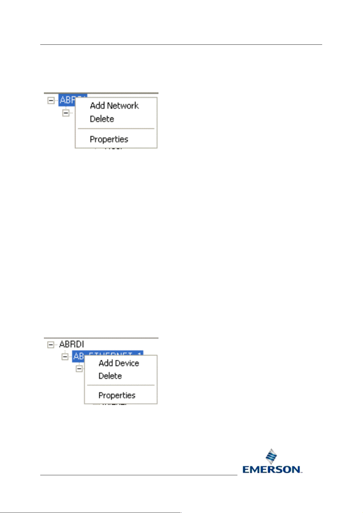
2.1.2 Driver Context Menu
The Driver Node context menu enables you to add a new Allen-Bradley Network, delete the Driver, or
modify the Driver's settings from it's Properties page.
2.1.2.1 Add Network
This option opens the Add Network General Dialog, which enables you to add a new Allen-Bradley
Network object.
2.1.2.2 Delete Driver
Selecting this option will delete the Allen-Bradley Driver. Database integrity restraints will not allow the
Driver deletion to succeed, unless all child Network, Device and Signal objects below it are deleted
first. The attempted deletion will begin immediately this option is chosen.
2.1.2.3 Driver Properties
This option displays the Driver General Dialog, which allows you to modify settings for the AllenBradley driver.
2.1.3 Network Node
Network nodes correspond to entries in the abnetwork table. A plus sign to the left of a node
indicates the presence of objects under the parent object. A right mouse click on the Network node
reveals a context menu.
2.1.4 Network Context Menu
The Network Node context menu enables you to add a new Allen-Bradley Device, delete the Network,
or modify the Network's settings from it's Properties page.
2.1.4.1 Add Device
This option opens the Add Device General Dialog, which enables you to add a new Allen-Bradley
Device object.
Remote Automation Solutions
Website: www.EmersonProcess.com/Remote
Page 11

Reference Guide
D5092
11-Dec-2007 - Page 11
2.1.4.2 Delete Network
Selecting this option will delete the Allen-Bradley Network. Database integrity restraints will not allow
the Network deletion to succeed, unless all child Device and Signal objects below it are deleted first.
The attempted deletion will begin immediately this option is chosen.
2.1.4.3 Network Properties
Allen-Bradley Configuration
This option displays the Network
Bradley Network.
General Dialog, which allows you to modify settings for the Allen-
2.1.5 Device Node
A Device Node corresponds to a Device object in the abdevice table. If the Device node contains
signals, a plus sign will exist to the left of it. Selecting the plus sign will display the Signal nodes. A
right click on the Device node will display the Device Node context menu.
2.1.6 Device Context Menu
The Device Node context menu enables you to add a new Allen-Bradley Signal or Poll List, delete the
Device, or modify the Device's settings from it's Properties page.
2.1.6.1 Add Signal
This option opens the Add Signal Dialog, which enables you to add a new Allen-Bradley Signal
object.
2.1.6.2 Add Poll List
This option opens the Add Poll List Dialog, which enables you to add a new Allen-Bradley Signal Poll
List.
2.1.6.3 Delete Device
Selecting this option will delete the Allen-Bradley Device. Database integrity restraints will not allow
the Device deletion to succeed, unless all child Signal or Poll List objects below it are deleted first.
The attempted deletion will begin immediately this option is chosen.
2.1.6.4 Device Properties
This option displays the Device General Dialog, which allows you to modify settings for the AllenBradley Network.
Remote Automation Solutions
Website: www.EmersonProcess.com/Remote
Page 12

Reference Guide
D5092
11-Dec-2007 - Page 12
Allen-Bradley Configuration
2.1.7 Signal Nodes
At the bottom of the tree are the signal type nodes and the poll list node. Depending on the types of
signals present in the Device, the possible nodes are: -
• Digital
• Integer
• Real
• Complex
• PollList
These nodes do not have a plus sign to indicate the presence of individual objects under them.
Individual signals or poll lists are shown in the list pane when their associated node is selected in the
tree. Alarm conditions are displayed on a property page of the associated signal. Signals of each type
or a Poll List can be added by accessing the context menu on each of the different Nodes.
2.2 List Pane
The details of the items from the selected tables in the Tree Pane are displayed here. Context menus
are available from the objects on display within this pane. The context menu available will depend on
the type of object that has been selected. Below is a list of the possible nodes selected from the Tree
pane, and the context menus that will be available by selecting the object or objects that appear in the
List pane.
Node Selected from Tree Pane
Driver Driver Context Menu
Network Network Context Menu
Device Device Context Menu
Signal or Poll List Node Signal Nodes Context Menus
Context Menu Available in List Pane
Remote Automation Solutions
Website: www.EmersonProcess.com/Remote
Page 13
Reference Guide
D5092
11-Dec-2007 - Page 13
Allen-Bradley Configuration
3 Adding Items
The general rule for adding objects is to click on an object in either the Tree View pane or the List
pane, and select the 'Add' option if one is available.
The list of items that can be added is as follows: -
• Network
• Device
• Signal
• Poll List
• Alarm Condition
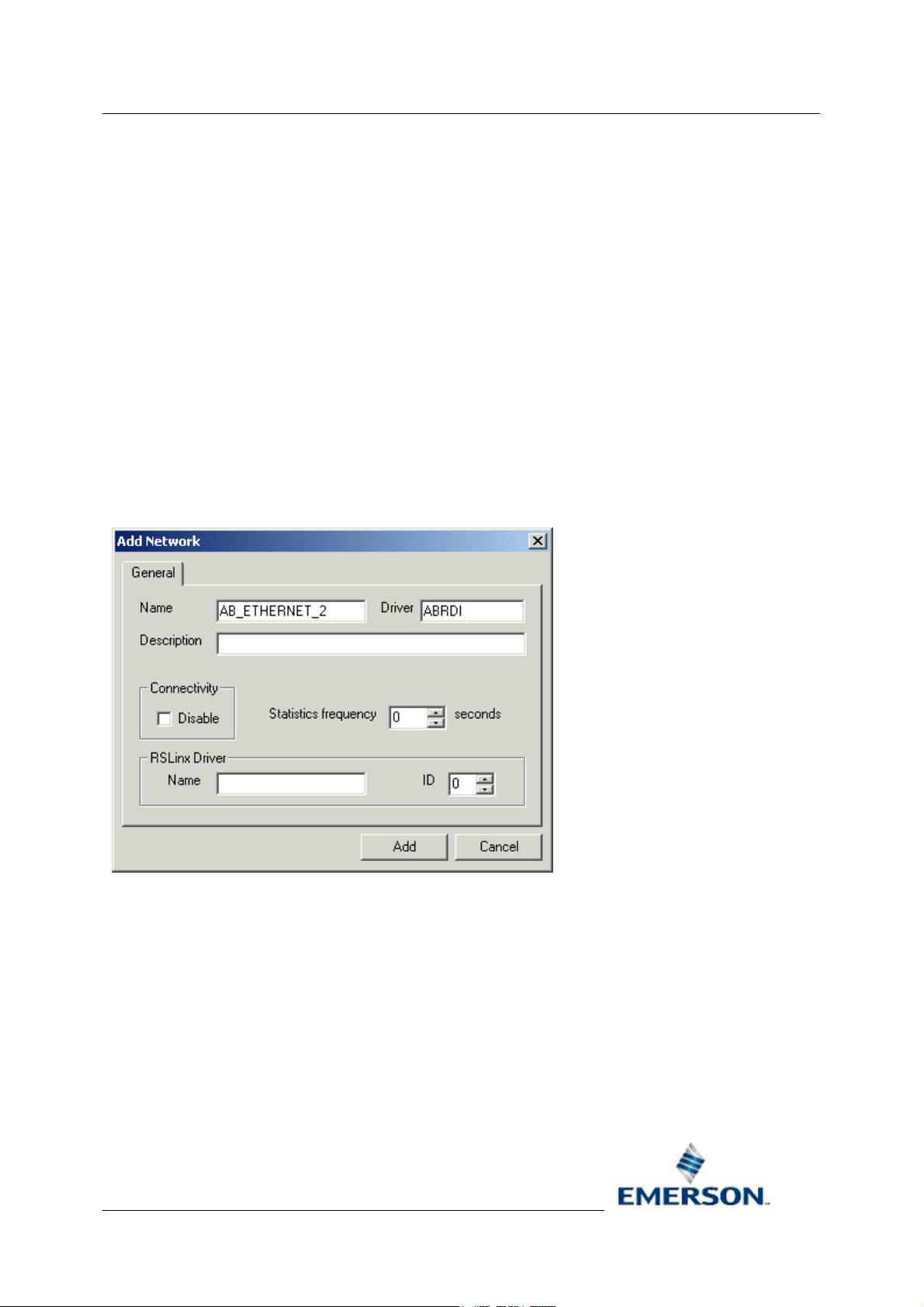
3.1 Networks
The Add Network General dialog enables the user to add a new Network object.
3.1.1 Network Name
The name of the Allen-Bradley Network. The name is arbitrary, but must be unique for each AllenBradley Network.
3.1.2 Driver
The name of the parent driver (in this case the Allen-Bradley RDI).
3.1.3 Network Description
An arbitrary string used to describe the network in more detail.
Remote Automation Solutions
Website: www.EmersonProcess.com/Remote
Page 14

Reference Guide
D5092
11-Dec-2007 - Page 14
Allen-Bradley Configuration
3.1.4 Disable Network
Used to enable or disable the ABRDI network. Off by default (enabled).
3.1.5 Statics Frequency
Specifies the frequency at which the ABRDI updates the RTRDB with statistics.
3.1.6 RSLinx Driver Name
This field Identifies the RSLINX driver, which should be configured to run as part of the
OpenEnterprise session.
3.1.7 AB Network ID
Arbitrary number between one and fifteen. It represents the AB network interface ID.
3.2 Devices
The Add Device General dialog enables the user to add a new Device.
3.2.1 Device Name
Arbitrary, unique name for the device.
3.2.2 Network
The name of the parent network.
Remote Automation Solutions
Website: www.EmersonProcess.com/Remote
Page 15

Reference Guide
D5092
11-Dec-2007 - Page 15
Allen-Bradley Configuration
3.2.3 Device Description
An arbitrary string used to describe the device in greater detail.
3.2.4 Address
Identifies the AB RSLINX Port ID and station number. This PLC is also known as the 'A' PLC.
3.2.5 Disable Device
Used to enable or disable the ABRDI device. Off by default (enabled).
3.2.6 Device Check Period
Optional sanity check between the OpenEnterprise Database and ABRDI. If set, the OE Database will
request a device sanity check for the device if the device has not been heard from as specified by the
CheckPeriod time.
3.2.7 Redundant
Set to TRUE if this is a redundant PLC. Otherwise set to FALSE.
3.2.8 Backup Address
Identifies the back-up AB RSLINX Port ID and station number. Used for redundant systems only.
Same format as deviceaddress. This PLC is also known as the 'B' PLC.
3.2.9 Main Indicator
The address within the PLC used to indicate if the PLC is Master or Standby. Only used for redundant
systems. e.g. 'N31:0/0'
3.2.10 Schedule Interval
The default time interval for polling data from this device.
3.2.11 Schedule ID
The ID of the default time schedule for polling data from this device (this alternative way of specifying
a schedule interval reflects the way these intervals are managed in the OE Database).
3.2.12 Heartbeat Address
The address within the PLC used by the ABRDI to send heartbeats (e.g. update with value 1) to act
as a RDI to PLC heartbeat.
3.2.13 Heartbeat Rate
The rate at which the ABRDI will update the Heartbeat value. Specified in seconds.
3.3 Signals
There are four signal types which can be added. Click on the appropriate signal type to go to it's
dialog:-
Remote Automation Solutions
Website: www.EmersonProcess.com/Remote
Page 16

Reference Guide
D5092
11-Dec-2007 - Page 16
1. Digital Signals
2. Real Signals
3. Integer Signals
4. Complex Signals
Allen-Bradley Configuration
3.3.1 Add Digital Signal General Dialog
The Add Digital Signal dialog enables the user to add a new Allen-Bradley Signal to the
OpenEnterprise database. If the dialog is displayed from a Device node or object, then it is displayed
as a tab on the Add Signal dialog, but if it is displayed from a Signal Node or a Signal object, it will be
displayed as a single tab.
3.3.1.1 Name
Arbitrary, unique name for the object. Must be entered by the user. When modifying, this attribute is
disabled because it is a primary key.
3.3.1.2 Description
An arbitrary string used to describe the object in greater detail.
Remote Automation Solutions
Website: www.EmersonProcess.com/Remote
Page 17

Reference Guide
D5092
11-Dec-2007 - Page 17
3.3.1.3 On Units Text
A string displayed when the signal is on.
3.3.1.4 Off Units Text
A string displayed when the signal is off.
3.3.1.5 Device
The name of the parent device. This is added automatically.
3.3.1.6 File Address
The PLC address. The format varies slightly between signal types. Must be entered by the user.
Digital
An Allen-Bradley digital signal maps to a single 'bit' of data in the PLC. For instance, an example File
address for a digital signal is 'B3:0/0'.
Real
Allen-Bradley Configuration
An Allen-Bradley real signal maps to a single word (F or N) in the PLC. Examples of File addresses
for a real signal are 'F100:0' and 'N101:0'.
Integer
An Allen-Bradley integer signal maps to a single word of integer (N) data in the PLC. An example of
File address for an integer signal is 'N101:0'.
Complex
An Allen-Bradley complex signal maps to a single word of integer (N) data in the PLC. An example of
File address for a complex signal is 'T101:0'.
3.3.1.7 Display
The filename of the display associated with this signal.
3.3.1.8 Plant Area
The plantarea associated with this signal. A drop-down list is available.
3.3.1.9 Access Area
The accessarea associated with this signal. A drop-down list is available.
3.3.1.10 Callout Area
The calloutarea associated with this signal.
Remote Automation Solutions
Website: www.EmersonProcess.com/Remote
Page 18

Reference Guide
D5092
11-Dec-2007 - Page 18
Allen-Bradley Configuration
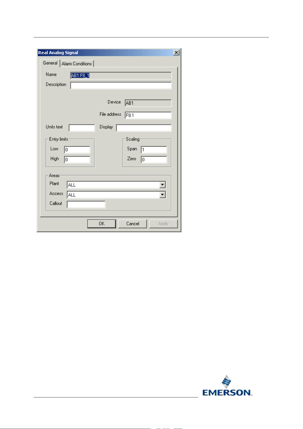
3.3.2 Add Real Signal General Dialog
The Add Real Signal dialog enables the user to add a new Allen-Bradley Signal to the
OpenEnterprise database. If the dialog is displayed from a Device node or object, then it is displayed
as a tab on the Add Signal dialog, but if it is displayed from a Signal Node or a Signal object, it will be
displayed as a single tab.
3.3.2.1 Name
Arbitrary, unique name for the object. Must be entered by the user. When modifying, this attribute is
disabled because it is a primary key.
3.3.2.2 Description
An arbitrary string used to describe the object in greater detail.
3.3.2.3 Device
The name of the parent device. This is added automatically.
3.3.2.4 File Address
The PLC address. The format varies slightly between signal types. Must be entered by the user.
Remote Automation Solutions
Website: www.EmersonProcess.com/Remote
Page 19

Reference Guide
D5092
11-Dec-2007 - Page 19
Digital
An Allen-Bradley digital signal maps to a single 'bit' of data in the PLC. For instance, an example File
address for a digital signal is 'B3:0/0'.
Real
An Allen-Bradley real signal maps to a single word (F or N) in the PLC. Examples of File addresses
for a real signal are 'F100:0' and 'N101:0'.
Integer
An Allen-Bradley integer signal maps to a single word of integer (N) data in the PLC. An example of
File address for an integer signal is 'N101:0'.
Complex
An Allen-Bradley complex signal maps to a single word of integer (N) data in the PLC. An example of
File address for a complex signal is 'T101:0'.
3.3.2.5 Display
Allen-Bradley Configuration
The filename of the display associated with this signal.
3.3.2.6 Units Text
A string describing the units used for the value.
3.3.2.7 Low Entry Limit
Low entry limit applied to signal value updates.
3.3.2.8 High Entry Limit
High entry limit applied to signal value updates.
3.3.2.9 Span
The 'm' in y = mx + c. Where 'y' is the database value and 'x' is the PLC value. Used to adjust an
integer value to a float.
3.3.2.10 Zero
The 'c' in y = mx + c. Where 'y' is the database value and 'x' is the PLC value. Used to adjust an
integer to a float.
3.3.2.11 Plant Area
The plantarea associated with this signal. A drop-down list is available.
3.3.2.12 Access Area
The accessarea associated with this signal. A drop-down list is available.
3.3.2.13 Callout Area
The calloutarea associated with this signal.
Remote Automation Solutions
Website: www.EmersonProcess.com/Remote
Page 20

Reference Guide
D5092
11-Dec-2007 - Page 20
Allen-Bradley Configuration
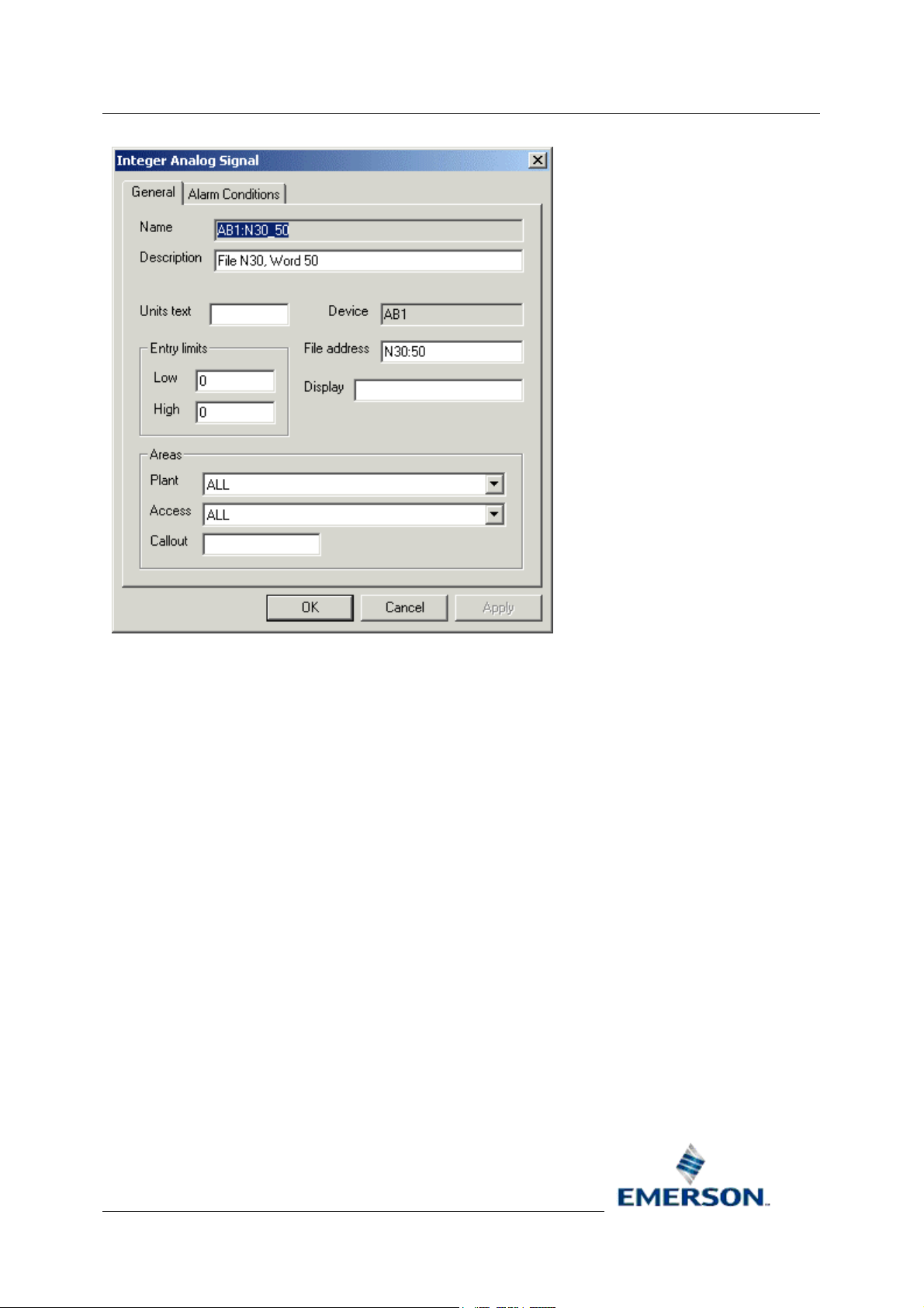
3.3.3 Add Integer Signal General Dialog
The Add Integer Signal dialog enables the user to add a new Allen-Bradley Signal to the
OpenEnterprise database. If the dialog is displayed from a Device node or object, then it is displayed
as a tab on the Add Signal dialog, but if it is displayed from a Signal Node or a Signal object, it will be
displayed as a single tab.
3.3.3.1 Name
Arbitrary, unique name for the object. Must be entered by the user. When modifying, this attribute is
disabled because it is a primary key.
3.3.3.2 Description
An arbitrary string used to describe the object in greater detail.
3.3.3.3 Units Text
A string describing the units used for the value.
3.3.3.4 Device
The name of the parent device. This is added automatically.
Remote Automation Solutions
Website: www.EmersonProcess.com/Remote
Page 21

Reference Guide
D5092
11-Dec-2007 - Page 21
3.3.3.5 File Address
The PLC address. The format varies slightly between signal types. Must be entered by the user.
Digital
An Allen-Bradley digital signal maps to a single 'bit' of data in the PLC. For instance, an example File
address for a digital signal is 'B3:0/0'.
Real
An Allen-Bradley real signal maps to a single word (F or N) in the PLC. Examples of File addresses
for a real signal are 'F100:0' and 'N101:0'.
Integer
An Allen-Bradley integer signal maps to a single word of integer (N) data in the PLC. An example of
File address for an integer signal is 'N101:0'.
Complex
An Allen-Bradley complex signal maps to a single word of integer (N) data in the PLC. An example of
File address for a complex signal is 'T101:0'.
Allen-Bradley Configuration
3.3.3.6 Display
The filename of the display associated with this signal.
3.3.3.7 Low Entry Limit
Low entry limit applied to signal value updates.
3.3.3.8 High Entry Limit
High entry limit applied to signal value updates.
3.3.3.9 Plant Area
The plantarea associated with this signal. A drop-down list is available.
3.3.3.10 Access Area
The accessarea associated with this signal. A drop-down list is available.
3.3.3.11 Callout Area
The calloutarea associated with this signal.
3.3.4 Add Complex Signal General Dialog
The Add Complex Signal dialog enables the user to add a new Allen-Bradley Signal to the
OpenEnterprise database. If the dialog is displayed from a Device node or object, then it is displayed
as a tab on the Add Signal dialog, but if it is displayed from a Signal Node or a Signal object, it will be
displayed as a single tab.
Remote Automation Solutions
Website: www.EmersonProcess.com/Remote
Page 22

Reference Guide
D5092
11-Dec-2007 - Page 22
Allen-Bradley Configuration
3.3.4.1 Name
Arbitrary, unique name for the object. Must be entered by the user. When modifying, this attribute is
disabled because it is a primary key.
3.3.4.2 Description
An arbitrary string used to describe the object in greater detail.
3.3.4.3 Device
The name of the parent device. This is added automatically.
3.3.4.4 File Address
The PLC address. The format varies slightly between signal types. Must be entered by the user.
3.3.4.4.1 Digital
An Allen-Bradley digital signal maps to a single 'bit' of data in the PLC. For instance, an example File
address for a digital signal is 'B3:0/0'.
Remote Automation Solutions
Website: www.EmersonProcess.com/Remote
Page 23

Reference Guide
D5092
11-Dec-2007 - Page 23
3.3.4.4.2 Real
An Allen-Bradley real signal maps to a single word (F or N) in the PLC. Examples of File addresses
for a real signal are 'F100:0' and 'N101:0'.
3.3.4.4.3 Integer
An Allen-Bradley integer signal maps to a single word of integer (N) data in the PLC. An example of
File address for an integer signal is 'N101:0'.
3.3.4.4.4 Complex
An Allen-Bradley complex signal maps to a single word of integer (N) data in the PLC. An example of
File address for a complex signal is 'T101:0'.
3.3.4.5 Display
The filename of the display associated with this signal.
3.3.4.6 Plant Area
The plantarea associated with this signal. A drop-down list is available.
Allen-Bradley Configuration
3.3.4.7 Access Area
The accessarea associated with this signal. A drop-down list is available.
3.3.4.8 Callout Area
The calloutarea associated with this signal.
3.4 Poll Lists
The Add Poll List dialog enables the user to add a new Allen-Bradley Poll List to the OpenEnterprise
database. The dialog can be displayed from the context menu of a Device node or Poll List object.
Remote Automation Solutions
Website: www.EmersonProcess.com/Remote
Page 24

Reference Guide
D5092
11-Dec-2007 - Page 24
Allen-Bradley Configuration
3.4.1 Name
Arbitrary, unique name for the poll list.
3.4.2 Description
An arbitrary string used to describe the poll list in greater detail.
3.4.3 File
The PLC File. E.g. 'B3' or 'N100'.
3.4.4 Start Address
The first address in the address range to be polled by this poll list.
3.4.5 End Address
The last address in the address range to be polled by this poll list. If a poll list is created with a valid
start address but no end address, then the OE Database will attempt to auto-configure the end
address based on the configured signals in the OE Database.
3.4.6 Auto End Address
If set to TRUE then the value of the EndAddress will be automatically set to reflect the highest
address of any configured signals. If set to FALSE then the setting of the EndAddress will be the
responsibility of the system configurer.
3.4.7 Access Area
The accessarea associated with this poll list.
Remote Automation Solutions
Website: www.EmersonProcess.com/Remote
Page 25

Reference Guide
D5092
11-Dec-2007 - Page 25
Allen-Bradley Configuration
3.4.8 Schedule ID
References the DVI_Schedule entry that controls the frequency at which this data is polled from the
PLC.
3.4.9 Disable Poll List
Used to enable or disable the poll list.
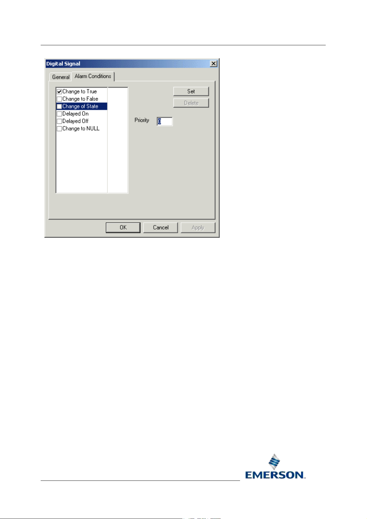
3.5 Alarm Conditions
An alarm condition can only be added once the Signal to which it applies exists. To add an alarm
condition to a signal, select the signal from the List view and click on the 'Properties' option, as shown
in the example below.
Then select the 'Alarm Conditions' tab:-
There are three types of Signals which can be configured to have Alarm Conditions: -
• Digital
• RealAnalog
• Integer
3.5.1 Digital Alarm Conditions Dialog
The [Set] button in the dialog below is enabled, but there is no check next to the alarm condition,
indicating that the new alarm condition has not yet added to the OE database.
Remote Automation Solutions
Website: www.EmersonProcess.com/Remote
Page 26

Reference Guide
D5092
11-Dec-2007 - Page 26
Allen-Bradley Configuration
3.5.1.1 Alarm Condition Tick List
This list displays the alarm conditions available for the signal type. A check next to an alarm condition
indicates that the alarm condition is already configured or will be added for the selected signal when
the [Set] button is clicked.
3.5.1.2 Set Button
This button only becomes enabled when the user has filled in the necessary information on the dialog,
which varies according to which type of signal and alarm condition is selected. When this button is
enabled and clicked the selected alarm condition will added to the OE database and the alarm
condition will be checked on the dialog to indicate this .
3.5.1.3 Condition Details
This section is populated with the condition details. This includes the alarm priority for the condition
and various other values, depending on the signal type.
3.5.2 Real Alarm Conditions Dialog
The [Set] button is disabled in the example dialog below, indicating that the selected alarm condition
has already been configured.
Remote Automation Solutions
Website: www.EmersonProcess.com/Remote
Page 27

Reference Guide
D5092
11-Dec-2007 - Page 27
Allen-Bradley Configuration
3.5.2.1 Alarm Condition Tick List
This list displays the alarm conditions available for the signal type. A check next to an alarm condition
indicates that the alarm condition is already configured or will be added for the selected signal when
the [Set] button is clicked.
3.5.2.2 Set Button
This button only becomes enabled when the user has filled in the necessary information on the dialog,
which varies according to which type of signal and alarm condition is selected. When this button is
enabled and clicked the selected alarm condition will added to the OE database and the alarm
condition will be checked on the dialog to indicate this .
3.5.2.3 Condition Details
This section is populated with the condition details. This includes the alarm priority for the condition
and various other values, depending on the signal type.
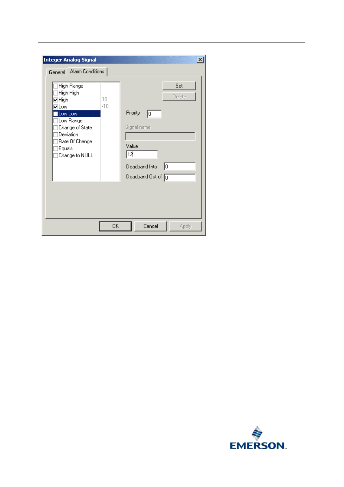
3.5.3 Integer Alarm Conditions Dialog
The [Set] button in the dialog below is enabled, but there is no check next to the alarm condition,
indicating that the new alarm condition has not yet added to the OE database.
Remote Automation Solutions
Website: www.EmersonProcess.com/Remote
Page 28
Reference Guide
D5092
11-Dec-2007 - Page 28
Allen-Bradley Configuration
3.5.3.1 Alarm Condition Tick List
This list displays the alarm conditions available for the signal type. A check next to an alarm condition
indicates that the alarm condition is already configured or will be added for the selected signal when
the [Set] button is clicked.
3.5.3.2 Set Button
This button only becomes enabled when the user has filled in the necessary information on the dialog,
which varies according to which type of signal and alarm condition is selected. When this button is
enabled and clicked the selected alarm condition will added to the OE database and the alarm
condition will be checked on the dialog to indicate this .
3.5.3.3 Condition Details
This section is populated with the condition details. This includes the alarm priority for the condition
and various other values, depending on the signal type.
Remote Automation Solutions
Website: www.EmersonProcess.com/Remote
Page 29
Reference Guide
D5092
11-Dec-2007 - Page 29
Allen-Bradley Configuration
4 Modifying Items
The general rule for modifying objects is to select the object from either the Tree or List pane, then
right click and select the Properties option. This will display the Property page for the object, which
can then be modified.
The objects that can be modified in this way are: -
• Driver
• Network
• Device
• Signal
• Alarm Condition
• Poll List
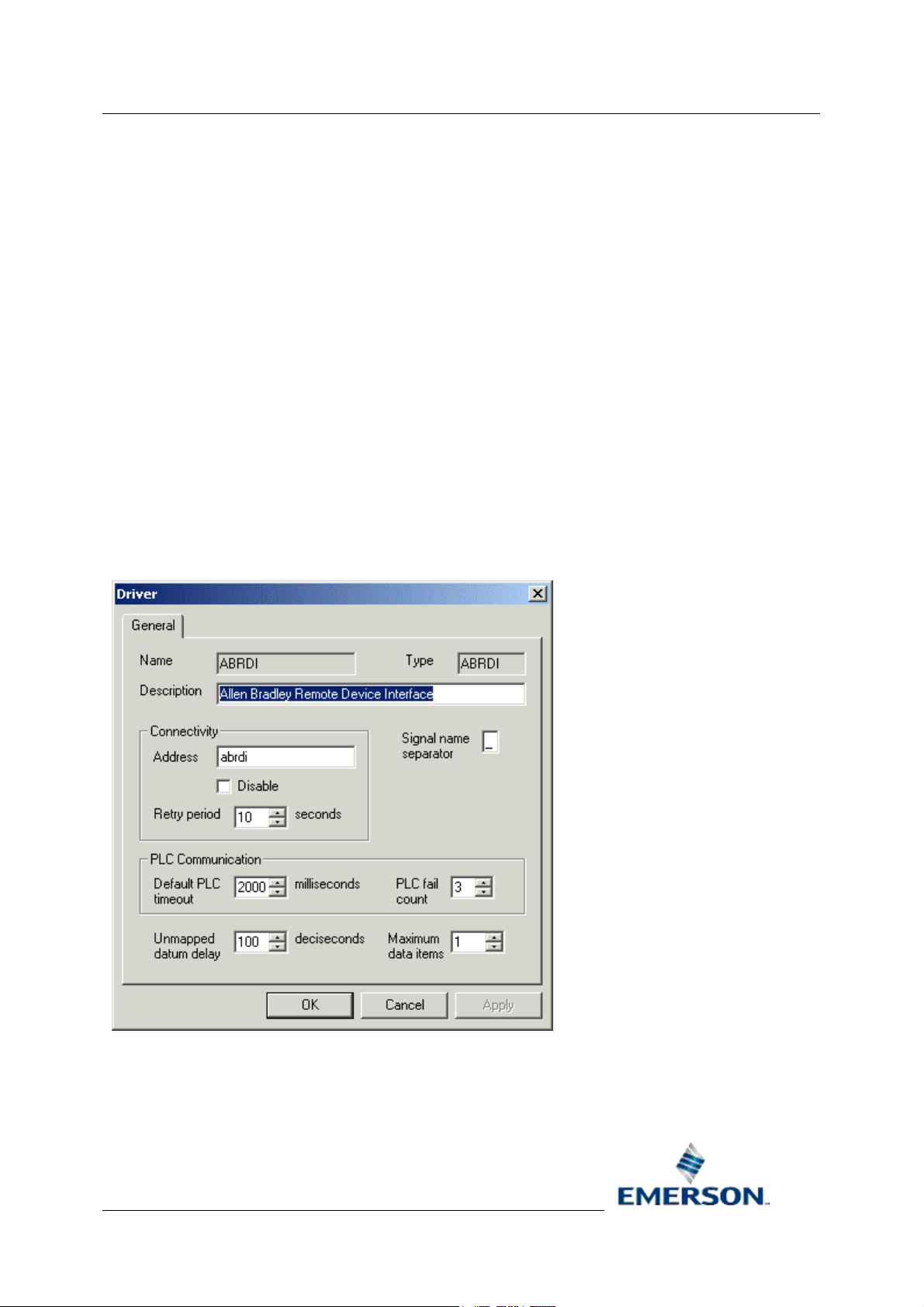
4.1 Driver General Dialog
The Driver General Page enables the user to modify settings for the Allen-Bradley RDI driver.
4.1.1 Driver Name
The name of the Driver. It is disabled when in modify mode, and cannot be changed.
Remote Automation Solutions
Website: www.EmersonProcess.com/Remote
Page 30

Reference Guide
D5092
11-Dec-2007 - Page 30
Allen-Bradley Configuration
4.1.2 Type
The driver type.
4.1.3 Driver Description
An arbitrary string used to describe the driver.
4.1.4 Driver Address
The TCP/IP service name used; offered by the ABRDI.
4.1.5 Driver Disable
Used to enable or disable the ABRDI interface. Off by default (enabled).
4.1.6 Retry Period
The time allocated between connection retries.
4.1.7 Signal Name Separator
The character used with signal names to break the name into base, extension attribute.
4.1.8 Default PLC Timeout
Default timeout value used when communicating with AB PLCs.
4.1.9 PLC Fail Count
The number of consecutive I/O failures to a PLC that will result in the PLC being marked as offline.
4.1.10 Unmapped Datum Delay
The amount of time after abrdi start-up until all devices are checked for having registered signals that
are not being collected by any poll lists.
4.1.11 Maximum Data Items
Maximum number of data items. Range 1 to 500.
4.2 Network General Dialog
The Network General Page enables the user to modify settings for Allen-Bradley Network objects.
Remote Automation Solutions
Website: www.EmersonProcess.com/Remote
Page 31

Reference Guide
D5092
11-Dec-2007 - Page 31
Allen-Bradley Configuration
4.2.1 Network Name
The name of the Allen-Bradley Network. The name is arbitrary, but must be unique for each AllenBradley Network.
4.2.2 Driver
The name of the parent driver (in this case the Allen-Bradley RDI).
4.2.3 Network Description
An arbitrary string used to describe the network in more detail.
4.2.4 Disable Network
Used to enable or disable the ABRDI network. Off by default (enabled).
4.2.5 Statics Frequency
Specifies the frequency at which the ABRDI updates the RTRDB with statistics.
4.2.6 RSLinx Driver Name
This field Identifies the RSLINX driver, which should be configured to run as part of the
OpenEnterprise session.
4.2.7 AB Network ID
Arbitrary number between one and fifteen. It represents the AB network interface ID.
4.3 Device General Dialog
The Device General Page enables the user to modify settings for Allen-Bradley Devices.
Remote Automation Solutions
Website: www.EmersonProcess.com/Remote
Page 32

Reference Guide
D5092
11-Dec-2007 - Page 32
Allen-Bradley Configuration
4.3.1 Device Name
Arbitrary, unique name for the device.
4.3.2 Network
The name of the parent network.
4.3.3 Device Description
An arbitrary string used to describe the device in greater detail.
4.3.4 Address
Identifies the AB RSLINX Port ID and station number. This PLC is also known as the 'A' PLC.
4.3.5 Redundant
Set to TRUE if this is a redundant PLC. Otherwise set to FALSE.
4.3.6 Disable Device
Used to enable or disable the ABRDI device. Off by default (enabled).
Remote Automation Solutions
Website: www.EmersonProcess.com/Remote
Page 33

Reference Guide
D5092
11-Dec-2007 - Page 33
Allen-Bradley Configuration
4.3.7 Device Check Period
Optional sanity check between the OpenEnterprise Database and ABRDI. If set, the OE Database will
request a device sanity check for the device if the device has not been heard from as specified by the
CheckPeriod time.
4.3.8 Schedule ID
The ID of the default time schedule for polling data from this device (this alternative way of specifying
a schedule interval reflects the way these intervals are managed in the OE Database).
4.3.9 Heartbeat Address
The address within the PLC used by the ABRDI to send heartbeats (e.g. update with value 1) to act
as a RDI to PLC heartbeat.
4.3.10 Heartbeat Rate
The rate at which the ABRDI will update the Heartbeat value. Specified in seconds.
4.4 Signal Dialogs
The Signal Property pages can be accessed from the context menu on Signal nodes in the Tree
pane, or from individual Signals in the List pane. The Signal Property pages available are: -
• Digital
• RealAnalog
• Integer
• Complex
4.4.1 Digital Signal General Dialog
The Digital Signal General Page enables the user to modify settings for an Allen-Bradley Digital
Signal.
Remote Automation Solutions
Website: www.EmersonProcess.com/Remote
Page 34

Reference Guide
D5092
11-Dec-2007 - Page 34
Allen-Bradley Configuration
4.4.1.1 Name
Arbitrary, unique name for the object. Must be entered by the user. When modifying, this attribute is
disabled because it is a primary key.
4.4.1.2 Description
An arbitrary string used to describe the object in greater detail.
4.4.1.3 On Units Text
A string displayed when the signal is on.
4.4.1.4 Off Units Text
A string displayed when the signal is off.
4.4.1.5 Device
The name of the parent device. This is added automatically.
4.4.1.6 File Address
The PLC address. The format varies slightly between signal types. Must be entered by the user.
4.4.1.6.1 Digital
An Allen-Bradley digital signal maps to a single 'bit' of data in the PLC. For instance, an example File
address for a digital signal is 'B3:0/0'.
Remote Automation Solutions
Website: www.EmersonProcess.com/Remote
Page 35

Reference Guide
D5092
11-Dec-2007 - Page 35
4.4.1.6.2 Real
An Allen-Bradley real signal maps to a single word (F or N) in the PLC. Examples of File addresses
for a real signal are 'F100:0' and 'N101:0'.
4.4.1.6.3 Integer
An Allen-Bradley integer signal maps to a single word of integer (N) data in the PLC. An example of
File address for an integer signal is 'N101:0'.
4.4.1.6.4 Complex
An Allen-Bradley complex signal maps to a single word of integer (N) data in the PLC. An example of
File address for a complex signal is 'T101:0'.
4.4.1.7 Display
The filename of the display associated with this signal.
4.4.1.8 Plant Area
The plantarea associated with this signal. A drop-down list is available.
Allen-Bradley Configuration
4.4.1.9 Access Area
The accessarea associated with this signal. A drop-down list is available.
4.4.1.10 Callout Area
The calloutarea associated with this signal.
4.4.2 Real Signal General Dialog
The Real Analog Signal General Page enables the user to modify settings for an Allen-Bradley Digital
Signal.
Remote Automation Solutions
Website: www.EmersonProcess.com/Remote
Page 36
Reference Guide
D5092
11-Dec-2007 - Page 36
Allen-Bradley Configuration
4.4.2.1 Name
Arbitrary, unique name for the object. Must be entered by the user. When modifying, this attribute is
disabled because it is a primary key.
4.4.2.2 Description
An arbitrary string used to describe the object in greater detail.
4.4.2.3 Device
The name of the parent device. This is added automatically.
4.4.2.4 Units Text
A string describing the units used for the value.
4.4.2.5 Display
The filename of the display associated with this signal.
Remote Automation Solutions
Website: www.EmersonProcess.com/Remote
Page 37

Reference Guide
D5092
11-Dec-2007 - Page 37
4.4.2.6 Low Entry Limit
Low entry limit applied to signal value updates.
4.4.2.7 High Entry Limit
High entry limit applied to signal value updates.
4.4.2.8 Span
The 'm' in y = mx + c. Where 'y' is the database value and 'x' is the PLC value. Used to adjust an
integer value to a float.
4.4.2.9 Zero
The 'c' in y = mx + c. Where 'y' is the database value and 'x' is the PLC value. Used to adjust an
integer to a float.
4.4.2.10 Plant Area
The plantarea associated with this signal. A drop-down list is available.
Allen-Bradley Configuration
4.4.2.11 Access Area
The accessarea associated with this signal. A drop-down list is available.
4.4.2.12 Callout Area
The calloutarea associated with this signal.
4.4.3 Integer Signal General Dialog
The Integer Signal General Page enables the user to modify settings for an Allen-Bradley Digital
Signal.
Remote Automation Solutions
Website: www.EmersonProcess.com/Remote
Page 38
Reference Guide
D5092
11-Dec-2007 - Page 38
Allen-Bradley Configuration
4.4.3.1 Name
Arbitrary, unique name for the object. Must be entered by the user. When modifying, this attribute is
disabled because it is a primary key.
4.4.3.2 Description
An arbitrary string used to describe the object in greater detail.
4.4.3.3 Device
The name of the parent device. This is added automatically.
4.4.3.4 Units Text
A string describing the units used for the value.
4.4.3.5 Display
The filename of the display associated with this signal.
4.4.3.6 Low Entry Limit
Low entry limit applied to signal value updates.
Remote Automation Solutions
Website: www.EmersonProcess.com/Remote
Page 39

Reference Guide
D5092
11-Dec-2007 - Page 39
4.4.3.7 High Entry Limit
High entry limit applied to signal value updates.
4.4.3.8 Span
The 'm' in y = mx + c. Where 'y' is the database value and 'x' is the PLC value. Used to adjust an
integer value to a float.
4.4.3.9 Zero
The 'c' in y = mx + c. Where 'y' is the database value and 'x' is the PLC value. Used to adjust an
integer to a float.
4.4.3.10 Plant Area
The plantarea associated with this signal. A drop-down list is available.
4.4.3.11 Access Area
The accessarea associated with this signal. A drop-down list is available.
Allen-Bradley Configuration
4.4.3.12 Callout Area
The calloutarea associated with this signal.
4.4.4 Complex Signal General Dialog
The Complex Signal General Page enables the user to modify settings for an Allen-Bradley Digital
Signal.
Remote Automation Solutions
Website: www.EmersonProcess.com/Remote
Page 40

Reference Guide
D5092
11-Dec-2007 - Page 40
Allen-Bradley Configuration
4.4.4.1 Name
Arbitrary, unique name for the object. Must be entered by the user. When modifying, this attribute is
disabled because it is a primary key.
4.4.4.2 Description
An arbitrary string used to describe the object in greater detail.
4.4.4.3 Device
The name of the parent device. This is added automatically.
4.4.4.4 File Address
The PLC address. The format varies slightly between signal types. Must be entered by the user.
4.4.4.4.1 Digital
An Allen-Bradley digital signal maps to a single 'bit' of data in the PLC. For instance, an example File
address for a digital signal is 'B3:0/0'.
4.4.4.4.2 Real
An Allen-Bradley real signal maps to a single word (F or N) in the PLC. Examples of File addresses
for a real signal are 'F100:0' and 'N101:0'.
Remote Automation Solutions
Website: www.EmersonProcess.com/Remote
Page 41

Reference Guide
D5092
11-Dec-2007 - Page 41
4.4.4.4.3 Integer
An Allen-Bradley integer signal maps to a single word of integer (N) data in the PLC. An example of
File address for an integer signal is 'N101:0'.
4.4.4.4.4 Complex
An Allen-Bradley complex signal maps to a single word of integer (N) data in the PLC. An example of
File address for a complex signal is 'T101:0'.
4.4.4.5 Display
The filename of the display associated with this signal.
4.4.4.6 Plant Area
The plantarea associated with this signal. A drop-down list is available.
4.4.4.7 Access Area
The accessarea associated with this signal. A drop-down list is available.
Allen-Bradley Configuration
4.4.4.8 Callout Area
The calloutarea associated with this signal.
4.5 Signal Alarm Conditions
Alarm Conditions can only be modified on a per signal basis. The individual signal must be selected
from the List pane, and then the Properties item selected from the context menu. Then on the Signal
Properties dialog, select the Alarm Condition tab. The Alarm Conditions that can be configured are: -
• Digital Alarm Condition
• RealAnalog Alarm Condition
• Integer Alarm Condition
4.5.1 Digital Alarm Conditions
The [Set] button in the dialog below is enabled, but there is no check next to the alarm condition,
indicating that the new alarm condition has not yet added to the OE database.
Remote Automation Solutions
Website: www.EmersonProcess.com/Remote
Page 42
Reference Guide
D5092
11-Dec-2007 - Page 42
Allen-Bradley Configuration
4.5.1.1 Alarm Condition Tick List
This list displays the alarm conditions available for the signal type. A check next to an alarm condition
indicates that the alarm condition is already configured or will be added for the selected signal when
the [Set] button is clicked.
4.5.1.2 Set Button
This button only becomes enabled when the user has filled in the necessary information on the dialog,
which varies according to which type of signal and alarm condition is selected. When this button is
enabled and clicked the selected alarm condition will added to the OE database and the alarm
condition will be checked on the dialog to indicate this .
4.5.1.3 Condition Details
This section is populated with the condition details. This includes the alarm priority for the condition
and various other values, depending on the signal type.
4.5.2 Real Alarm Conditions
The [Set] button is disabled in the example dialog below, indicating that the selected alarm condition
has already been configured.
Remote Automation Solutions
Website: www.EmersonProcess.com/Remote
Page 43

Reference Guide
D5092
11-Dec-2007 - Page 43
Allen-Bradley Configuration
4.5.2.1 Alarm Condition Tick List
This list displays the alarm conditions available for the signal type. A check next to an alarm condition
indicates that the alarm condition is already configured or will be added for the selected signal when
the [Set] button is clicked.
4.5.2.2 Set Button
This button only becomes enabled when the user has filled in the necessary information on the dialog,
which varies according to which type of signal and alarm condition is selected. When this button is
enabled and clicked the selected alarm condition will added to the OE database and the alarm
condition will be checked on the dialog to indicate this .
4.5.2.3 Condition Details
This section is populated with the condition details. This includes the alarm priority for the condition
and various other values, depending on the signal type.
4.5.3 Integer Alarm Conditions Dialog
The [Set] button in the dialog below is enabled, but there is no check next to the alarm condition,
indicating that the new alarm condition has not yet added to the OE database.
Remote Automation Solutions
Website: www.EmersonProcess.com/Remote
Page 44

Reference Guide
D5092
11-Dec-2007 - Page 44
Allen-Bradley Configuration
4.5.3.1 Alarm Condition Tick List
This list displays the alarm conditions available for the signal type. A check next to an alarm condition
indicates that the alarm condition is already configured or will be added for the selected signal when
the [Set] button is clicked.
4.5.3.2 Set Button
This button only becomes enabled when the user has filled in the necessary information on the dialog,
which varies according to which type of signal and alarm condition is selected. When this button is
enabled and clicked the selected alarm condition will added to the OE database and the alarm
condition will be checked on the dialog to indicate this .
4.5.3.3 Condition Details
This section is populated with the condition details. This includes the alarm priority for the condition
and various other values, depending on the signal type.
4.6 Poll List
The Poll List General Page enables the user to modify settings for an Allen-Bradley Poll List.
Remote Automation Solutions
Website: www.EmersonProcess.com/Remote
Page 45
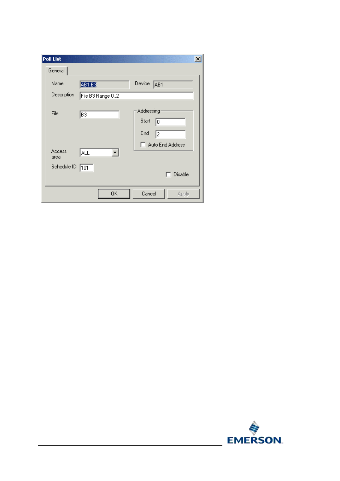
Reference Guide
D5092
11-Dec-2007 - Page 45
Allen-Bradley Configuration
4.6.1 Name
Arbitrary, unique name for the object. Must be entered by the user. When modifying, this attribute is
disabled because it is a primary key.
4.6.2 Description
An arbitrary string used to describe the object in greater detail.
4.6.3 Device
The name of the parent device. This is added automatically.
4.6.4 File
The PLC File. E.g. 'B3' or 'N100'.
4.6.5 Start Address
The first address in the address range to be polled by this poll list.
4.6.6 End Address
The last address in the address range to be polled by this poll list. If a poll list is created with a valid
start address but no end address, then the OE Database will attempt to auto-configure the end
address based on the configured signals in the OE Database.
Remote Automation Solutions
Website: www.EmersonProcess.com/Remote
Page 46

Reference Guide
D5092
11-Dec-2007 - Page 46
Allen-Bradley Configuration
4.6.7 Auto End Address
If set to TRUE then the value of the EndAddress will be automatically set to reflect the highest
address of any configured signals. If set to FALSE then the setting of the EndAddress will be the
responsibility of the system configurer.
4.6.8 Access Area
The accessarea associated with this signal. A drop-down list is available.
4.6.9 Schedule ID
The ID of the default time schedule for polling data from this device (this alternative way of specifying
a schedule interval reflects the way these intervals are managed in the OE Database).
4.6.10 Disable Poll List
Used to enable or disable the poll list.
Remote Automation Solutions
Website: www.EmersonProcess.com/Remote
Page 47
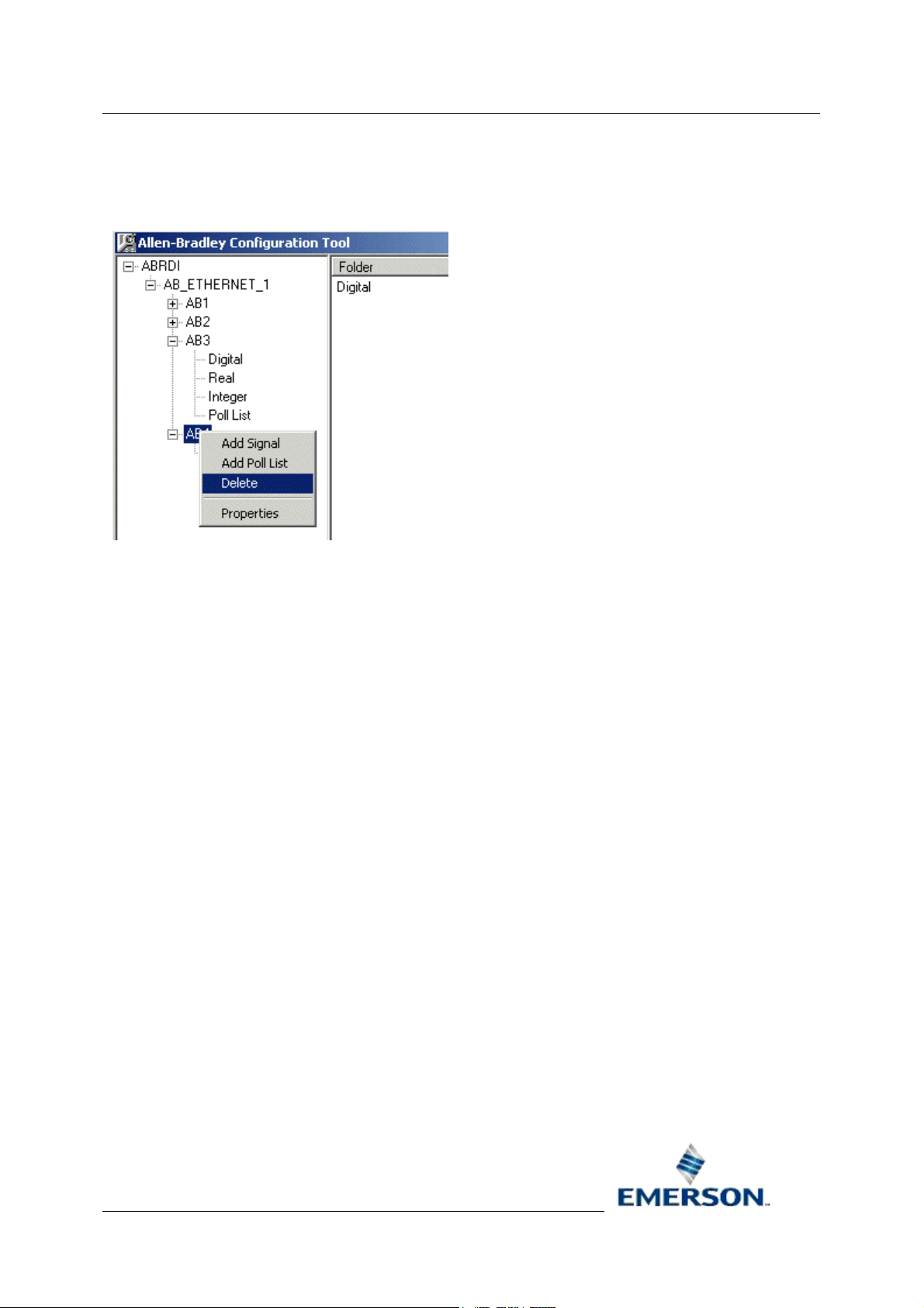
Reference Guide
D5092
11-Dec-2007 - Page 47
Allen-Bradley Configuration
5 Deleting Objects General Rules
To delete an object right click on it and select the 'Delete' option.
The selected object will be deleted without warning. If the deletion fails, a message will be provided
indicating the failure.
The most likely reason will be that the object was a parent to other objects, and that a deletion would
compromise database integrity.
Remote Automation Solutions
Website: www.EmersonProcess.com/Remote
Page 48

Reference Guide
D5092
11-Dec-2007 - Page 48
Allen-Bradley Configuration
6 PLC Addressing
The following uses some examples to demonstrate how to address Allen Bradley PLCs.
6.1.1.1.1 ABNetwork
An ABNetwork entry corresponds to an RSLinx Driver. The mapping is set-up using the
ABNetwork.RSLinxDriverName attribute. The following example shows how a configurationured
ABNetwork object should be named in order to correspond to the RSLinx Ethernet Driver.
ATTRIBUTE: RSLinxDriverName
VALUE: 'AB_ETH-1'
6.1.1.1.2 ABDevice
An ABDevice entry corresponds to an Allen Bradley PLC. The PLC can be standalone or redundant.
The mapping is set-up between the ABDevice.DeviceAddress and the appropriate RSLinx Driver
Station Mapping. The following example shows how an ABDevice entry maps to the configurationured
RSLinx Station 1 (Hostname 101.100.0.155).
ATTRIBUTE: DeviceAddress
VALUE: 'AB:LOCAL,1'
Remote Automation Solutions
Website: www.EmersonProcess.com/Remote
Page 49
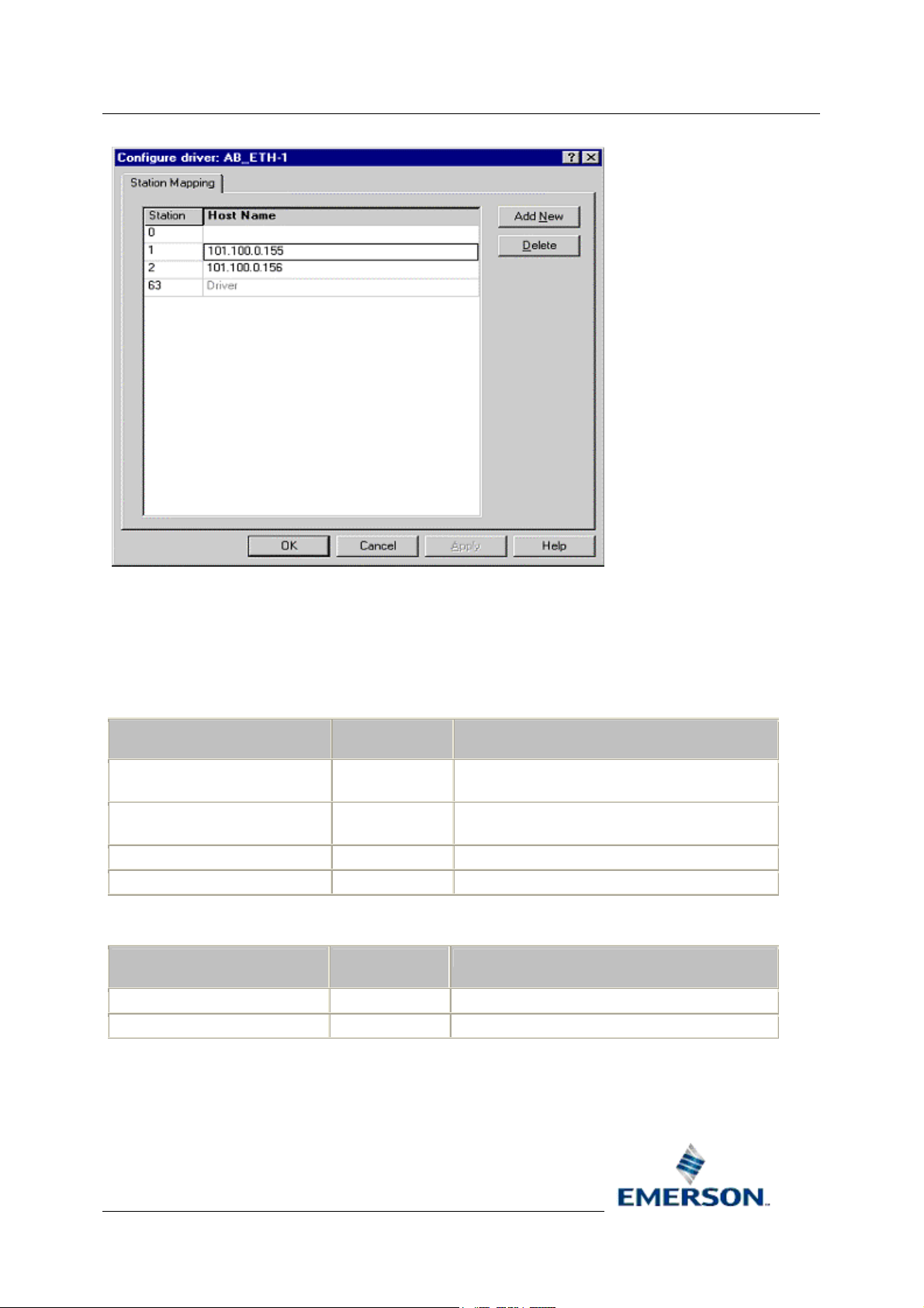
Reference Guide
D5092
11-Dec-2007 - Page 49
Allen-Bradley Configuration
6.1.1.1.3 Signals
OE signals are mapped to PLC file addresses. The file addresses mentioned are correct for PLC5s.
All addresses specified are in decimal unless otherwise stated. For example, all Input (I) and Output
(O) files use octal addressing.
6.1.1.1.4 ABDigital
FILE TYPE
Input - I I:004/00
Output - O O:004/00
Binary - B B3:1/0 File 3, Word 1, bit 0
Integer - N N7:98/1 File 7, Word 98, bit 1
6.1.1.1.5 ABIntegerAnalog
FILE TYPE
Integer - N N50:5 File 50, word 5
Status - S S:23 Status file, word 23 (internal time - minutes)
FILE ADDRESS COMMENTS
Input file, Word 4 octal, bit 0 octal
I:005/17
O:005/17
FILE
ADDRESS
Input file, Word 5 octal, bit 17 octal
Output file, Word 4 octal, bit 0 octal
Output file, Word 5 octal, bit 17 octal
COMMENTS
Remote Automation Solutions
Website: www.EmersonProcess.com/Remote
Page 50

Reference Guide
D5092
11-Dec-2007 - Page 50
6.1.1.1.6 ABRealAnalog
Allen-Bradley Configuration
FILE TYPE
Float - F F8:1 File 8, word 1
Integer - N N110:25 File 110, word 25.
6.1.1.1.7 ABPollList
FILE TYPE
Input - I I 4 15 Read Input file, word 4 to word 15 decimal (octal
Output - O O 4 5 Read Output file, word 4 to word 5. Note that the start
Binary - B B3 0 2 Read Binary file B3, word 0 to word 2, length 3
Integer - N N30 0 10 Read Integer file N30, word 0 to 10, length 11 words.
Float - F F8 5 55 Read Float file F8, word 5 to 55, length 51 words.
Status - S S 0 23 Read Status file, word 0 to word 23, length 24 words.
ADDRESS COMMENTS
FILE START END
FILE ADDRESS COMMENTS
word 17). Note this differs from the octal addressing
specified for Input file addresses for signals.
and end address must be specified in decimal. This
differs from the octal addressing specified for Output
file addresses for signals.
words.
Remote Automation Solutions
Website: www.EmersonProcess.com/Remote
Page 51

Reference Guide
D5092
11-Dec-2007 - Page 51
Allen-Bradley Configuration
7 Index
A
AB Config Tool
Running ................................................... 1
AB Config Tool ............................................ 1
AB Network ID..................................... 10, 32
Access Area15, 17, 19, 21, 36, 38, 40, 42, 47
Add Complex Signal General Dialog ........ 20
Add Device .................................................. 5
Add Device General Dialog....................... 10
Add Digital Signal General Dialog............. 13
Add Integer Signal General Dialog ........... 17
Add Network................................................ 4
Add Network General Dialog....................... 9
Add Poll List ................................................ 6
Add Poll List General Dialog ..................... 22
Add Real Signal General Dialog ............... 15
Add Signal ................................................... 6
Adding
Alarm Conditions ................................... 23
Objects General Rules ............................ 9
Signals ................................................... 12
Adding ............................................. 9, 12, 23
Address ...........11, 14, 16, 19, 21, 33, 36, 41
Alarm Condition Tick List24, 25, 27, 43, 44, 45
Alarm Conditions
Adding ................................................... 23
Modifying ............................................... 42
Alarm Conditions ................................. 23, 42
Auto End Address ............................... 23, 47
B
Backup Address ........................................ 12
C
Callout Area .... 15, 17, 19, 21, 36, 38, 40, 42
Complex Signal General Dialog ................ 40
Condition Details ......... 25, 26, 27, 43, 45, 46
D
Default PLC Timeout................................. 31
Delete Device .............................................. 6
Delete Driver ............................................... 4
Remote Automation Solutions
Website: www.EmersonProcess.com/Remote
Delete Network ............................................5
Deleting
Objects General Rules ...........................49
Deleting......................................................49
Description 14, 16, 18, 20, 35, 37, 39, 41, 46
Device....... 14, 16, 18, 21, 35, 37, 39, 41, 47
Device Check Period ...........................12, 34
Device Description...............................11, 33
Device General Dialog...............................32
Device Name .......................................11, 33
Device Node ................................................5
Device Node Context Menu.........................6
Device Properties ........................................6
Digital Alarm Conditions Dialog ...........24, 43
Digital Signal General Dialog.....................34
Disable Device.....................................11, 34
Disable Network...................................10, 32
Disable Poll List ...................................23, 47
Display ............ 14, 16, 19, 21, 36, 38, 39, 42
Driver ...................................................10, 32
Driver Address ...........................................30
Driver Description ......................................30
Driver Disable ............................................30
Driver General Dialog ................................29
Driver Name...............................................30
Driver Node..................................................4
Driver Node Context Menu ..........................4
Driver Properties..........................................4
E
End Address ........................................22, 47
H
Heartbeat Address...............................12, 34
Heartbeat Rate ....................................12, 34
High Entry Limit .......................17, 19, 38, 40
I
Integer Alarm Conditions Dialog..........26, 45
Integer Signal General Dialog ...................38
Interface.......................................................3
L
Page 52

Reference Guide
D5092
11-Dec-2007 - Page 52
Allen-Bradley Configuration
Low Entry Limit........................ 16, 19, 38, 40
M
Main Indicator............................................ 12
Maximum Data Items ................................ 31
Modifying
Alarm Conditions ................................... 42
Objects General Rules .......................... 29
Modifying ............................................. 29, 42
N
Name.........13, 15, 18, 20, 35, 37, 39, 41, 46
Network ............................................... 11, 33
Network Description ............................ 10, 32
Network General Dialog ............................ 31
Network Name ...................................... 9, 32
Network Node ............................................. 5
Network Node Context Menu ...................... 5
Network Properties...................................... 5
O
Objects General Rules
Adding ..................................................... 9
Deleting ................................................. 49
Modifying ............................................... 29
Objects General Rules .................... 9, 29, 49
Off Units Text ...................................... 14, 35
Overview ..................................................... 1
P
Pane ............................................................ 7
Plant Area........ 14, 17, 19, 21, 36, 38, 40, 42
PLC Addressing ........................................ 51
PLC Fail Count .......................................... 31
Poll List Access Area ................................ 23
Poll List Description................................... 22
Poll List General Dialog............................. 46
Poll List Name ........................................... 22
Poll List Schedule ID ................................. 23
Prerequisites ............................................... 1
Retry Period...............................................30
RSLinx Driver Name ............................10, 32
Running
AB Config Tool .........................................1
Running .......................................................1
S
Schedule ID ...................................12, 34, 47
Schedule Interval .......................................12
Set Button ................... 24, 26, 27, 43, 44, 46
Signal Dialogs............................................34
Signal Name Separator .............................31
Signal Nodes ...............................................6
Signals
Adding ....................................................12
Signals .......................................................12
Span ..............................................17, 38, 40
Start Address .......................................22, 47
Statics Frequency ................................10, 32
T
Tree Pane ....................................................3
Type...........................................................30
U
Units Text.................... 14, 16, 18, 35, 37, 39
Unmapped Datum Delay ...........................31
Z
Zero ...............................................17, 38, 40
R
Real Alarm Conditions Dialog ............. 25, 44
Real Signal General Dialog....................... 36
Redundant........................................... 12, 33
Remote Automation Solutions
Website: www.EmersonProcess.com/Remote
Page 53

Reference Guide
D5092
11-Dec-2007
NOTICE
Remote Automation Solutions (“RAS”), division of Emerson Process Management shall not be liable for technical or editorial errors in this manual or omissions from this
manual. RAS MAKES NO WARRANTIES, EXPRESSED OR IMPLIED, INCLUDING TH E IMPLIED WARRANTIES OF MERCHANTABILITY AND F ITNESS FOR A
PARTICULAR PURPOSE W ITH RESPECT TO THIS MANUAL AND, IN NO EVENT SHALL RAS BE LIABLE FOR ANY INCID ENTAL, PUNITIVE, SPECIAL OR
CONSEQUENTIAL DAMAGES INCLUDING, BUT NOT LIMITED TO, LOSS OF PRODUCTION, LOSS OF PROFITS, LOSS OF REVENUE OR USE AND COSTS
INCURRED INLCUDING WITHOUT LIMITATION FOR CAPITAL, FUEL AND POW ER, AND CLAIMS OF THIRD PARTIES.
Bristol, Inc., Bristol Babcock Ltd, Bristol Canada, BBI SA de CV and the Flow Computer Division are wholly owned subsidiaries of Emerson Electric Co. doing business as
Remote Automation Solutions (“RAS”), a division of Emerson Process Management. ROC, FloBoss, ROCLINK, Bristol, Bristol Babcock, ControlWave, TeleFlow and
Helicoid are trademarks of RAS. AMS, PlantWeb and the PlantWeb logo are marks of Emerson Electric Co. The Emerson logo is a trademark and service mark of the
Emerson Electric Co. All other trademarks are property of their respective owners.
The contents of this publication are presented for informational purposes only. While every effort has been made to ensure informational accuracy, they are not to be
construed as warranties or guarantees, express or implied, regarding the products or services described herein or their use or applicability. RAS reserves the right to
modify or improve the designs or specifications of such products at any time without notice. All sales are governed by RAS’ terms and conditions which are available
upon request.
RAS does not assume responsibility for the selection, use or maintenance of any product. Responsibility for proper selection, use and maintenance of any RAS product
remains solely with the purchaser and end-user.
Engineered and supported by:
Remote Automation Solutions,
Bristol Babcock Ltd. Blackpole Road, Worcester, WR3 8YB, UK
Reg office: 2nd Floor, Accurist House, 44 Baker Street, London, W1U 7AL
Registered in England and Wales, Reg No. 2580226
VAT Reg No. GB 880 9839 67
Allen-Bradley Configuration
Emerson Process Management
Remote Automation Solutions
1100 Buckingham St
Watertown, CT 06795
T 1 (860) 945 2200
F 1 (860) 945 2278
www.EmersonProcess.com/Remote
binfo@EmersonProcess.com
© 2007 Remote Automation Solutions, division of Emerson Process Management. All rights reserved.
Emerson Process Management
Remote Automation Solutions
Blackpole Road
Worcester, WR3 8YB
T 44 (0) 1905 856848
F 44 (0) 1905 856930
www.EmersonProcess.com/Remote
oedsupport@EmersonProcess.com
Loading...