

Remote Automation Solutions Gas Control Manager Program User Manual (FloBoss 107) Manuals & Guides
Page 1

Part D301749X012
August 2016
Gas Control Manager Program User
Manual (for FloBoss™ 107)
Remote Automation Solutions
Page 2

Gas Control Manager Program User Manual (FB107)
Page
Revision
All Pages
August-2016
Initial release
August-2014
Revision Tracking Sheet
August 2016
This manual may be revised periodically to incorporate new or updated information. The revision date of each
page appears at the bottom of the page opposite the page number. A change in revision date to any page also
changes the date of the manual that appears on the front cover. Listed below is the revision date of each page (if
applicable):
ii Revised Aug-16
Page 3

Gas Control Manager Program User Manual (FB107)
Contents
Chapter 1 – Introduction 1
1.1. Scope and Organization ................................................................................................................. 1
1.2. Product Overview ........................................................................................................................... 1
1.2.1. EFM Applicatio n s ............................................................................................................. 2
1.2.2. Cause and Effect .............................................................................................................. 2
1.2.3. Flow Summation............................................................................................................... 2
1.3. Program Requirements .................................................................................................................. 2
Chapter 2 – Installation 5
2.1. Installing the License Key ............................................................................................................... 5
2.2. Downloading the Program .............................................................................................................. 6
Chapter 3 – Configuration 11
3.1. EFM Applicatio n s .......................................................................................................................... 11
3.1.1. Run Switching – Run Switch Tab: Station Settings ....................................................... 12
3.1.2. Run Switching – Run Switch Tab: Tube Settings .......................................................... 17
3.1.3. Run Switching – Run Switch Operate Tab ..................................................................... 20
3.1.4. Run Switching – Proportional Output Tab ...................................................................... 21
3.1.5. Run Switching – Total Accum Tab ................................................................................. 22
3.1.6. About Open and Close DO ............................................................................................ 23
3.2. Cause and Effect .......................................................................................................................... 23
3.2.1. Effect Configuration Settings .......................................................................................... 25
3.2.2. Cause Configuration Settings ........................................................................................ 27
3.2.3. Cause and Effect Operate Display ................................................................................. 32
3.2.4. Configuration Examples ................................................................................................. 33
3.3. Flow Summation ........................................................................................................................... 41
3.3.1. Flow Sum ....................................................................................................................... 42
3.3.2. Examples ........................................................................................................................ 44
Chapter 4 – Reference 46
4.1. Point Type 22: Cause Configuration ............................................................................................ 47
4.2. Point Type 23: Effect Configuration .............................................................................................. 53
4.3. Point Type 35: Run Switching ...................................................................................................... 56
4.4. Point Type 36: Flow Sum ............................................................................................................. 66
Appendix A – Sample Cause and Effect Diagram 69
Revised Aug-16 iii
Page 4

Gas Control Manager Program User Manual (FB107)
[This page is intentionally left blank.]
iv Revised Aug-16
Page 5

Chapter 1 – Introduction
Gas Control Manager Program User Manual (FB107)
Caution
When implementing control using this product, observe best industry
practices as suggested by applicabl e and appropriate environmental,
health, and safety organizations. While this product can be used as A
safety component in a system, it is NOT intended o r designed to be the
ONLY safety mechanism in that system.
This chapter describes the structure of this manual and presents an
overview and installation instructions of the Gas Control Manager
Program for the FloBoss 107 (FB107).
1.1. Scope and Organization
This document is the user manual for the Gas Control Manager Program
for use in the FB107.
This manual describes how to download and configure this program
(referred to as the “Gas Control Manager Program” or “the program”
throughout the rest of this manual). You access and configure this program
using ROCLINK™ 800 Configuration Software (version 2.20 or greater)
loaded on a personal computer (PC) running Windows XP (with Service
Pack 3), Windows Vista™ (32-bit), Windows 7 (32-bit and 64-bit), or
Windows 8 (32-bit and 64-bit).
The sections in this manual provide information in a sequence appropriate
for first-time users. Once you become familiar with the procedures and the
software running in a FB107, the manual becomes a reference tool.
This manual has the following major sections:
Chapter 1 – Introduction
Chapter 2 – Installation
Chapter 3 – Configuration
Chapter 4 – Reference
This manual assumes that you are familiar with the FB107 and its
configuration. For more information, refer to the following manuals:
FloBoss 107 Flow Manager Instruction Manual (D301232X012)
ROCLINK 800 Configuration Software User Manual (for FB107)
1.2. Product Overview
The Gas Control Manager Program has two major components: EFM
Applications and Cause and Effect. This manual describes both
components, as well as an additional feature, Flow Summation.
(D301249X012)
Revised Aug-16 1
Page 6

Gas Control Manager Program User Manual (FB107)
1.2.1. EFM Applications
The Gas Control Manager program enables you to configure the FB107 to
perform common gas measurement (EFM) functions, including station
emergency shutdown, output of a 4-20 mA signal proportional to an input
or calculation, reset total meter accumulators for volume/energy, and run
switching. Normally, you would have to write a series FSTs to accomplish
these tasks; the program simplified the management of these and other
EFM-related tasks.
1.2.2. Cause and Effect
The program supports 16 causes and 8 effects, enabling you to perform
logical operations without writing FSTs. Typically, a cause monitors a
selected point that the program logically evaluates against a setpoint you
define. Any tripped cause linked to an effect forces the action defined in
that effect. The design of the configuration screens enables you to
configure this logic using a Cause & Effect matrix. In many cases you can
input the effects and causes line by line through the entire matrix. Each
cause configuration screen and effect configuration screen applies to a tag
line in your Cause & Effect matrix.
1.2.3. Flow Summation
An additional feature of the Gas Control Management program is the
ability to sum station values, totalizing any selected meter runs into flow
or volume results for station 1 or 2. You can then place volume and energy
results into softpoint tables or access those values directly through their
TLPs. Resettable total station accumulators are available according to the
totalization selections as well for station 1 or 2.
Station Total Accumulators for volume and energy accumulate selected
meter runs as totalized amount until you manually reset the accumulators.
The point parameters used accumulate to a huge number, and (for all
practical purposes) will never reach a roll-over point.
1.3. Program Requirements
You download the Gas Control Manager Program to the Flash and RAM
memory on the FB107 with firmware version 1.60 (or greater). Download
and configure the program using ROCLINK 800 Configuration software
version 2.20 (or greater).
The downloadable program is:
File Name
Target Unit/
Version
User Defined
Points (UDP)
Flash Used
(in bytes)
DRAM Used
(in bytes)
ROCLINK 800
Version
Display
Number
GasControlMgr_
v305_02_1.bin
2 Revised Aug-16
FB107 1.60 22, 23, 35, 36 40260 16384 2.20
21, 22, 23,
35, 36
Page 7

Gas Control Manager Program User Manual (FB107)
Note: You must connect a PC to the FloBoss’s LOI port before starting
the download.
For information on viewing the memory allocation of user programs, refer
to the ROCLINK 800 Configuration Software User Manual (for FB107)
(D301249X012).
Revised Aug-16 3
Page 8

Gas Control Manager Program User Manual (FB107)
[This page is intentionally left blank.]
4 Revised Aug-16
Page 9

Chapter 2 – Installation
This section provides instructions for installing the Gas Control Manager
Program into the FB107. Read Section 1.3 of this manual for program
requirements.
Note: The program and license key can be installed in any order. The
manual shows the installation of the license key first.
2.1. Installing the License Key
A license key is required to use the Gas Control Manager Program. To
install a USB key-based license on the FB107:
1. Insert the USB license key in a USB port on your PC.
2. Select Utilities > License Key Administrator > Transfer Between
Device and Key from the ROCLINK 800 menu bar. The Transfer
Licenses Between a Device and a Key screen displays.
Gas Control Manager Program User Manual (FB107)
Figure 1. Transfer Licenses Between a Device and a Key
Note: This screen has three sections. The upper portion (Licenses on
Device) shows any software licenses installed on the FB107. The
middle portion (Licenses on Key) shows software licenses on the
license key. The lower portion of the screen (License Key Event
Log) provides a rolling log of the last eight events related to this
license key.
Revised Aug-16 5
Page 10

Gas Control Manager Program User Manual (FB107)
3. Select the key-based license you want to transfer to the FB107 (Read
Only Port, as shown in Figure 1).
4. Click Move to Device. ROCLINK moves one instance of the license
from the key to the FB107 and updates the screen.
Note: An FB107 can hold up to six different licenses, although you
can install only one instance of each license on the FB107.
When you click Move to Device, ROCLINK 800 moves only
one instance of the license onto the FB107 and automatically
decreases the license quantity on the USB key by one.
5. Verify the license name displays in the Licenses on Device section of
the screen. Proceed to Section 2.2 to download the user program.
2.2. Downloading the Program
This section provides instructions for installing the user program into
FloBoss memory.
Note: Connect a PC to the FloBoss’s LOI port before starting the
download.
To download the user program:
Figure 2. License Installed
1. Start and logon to ROCLINK 800.
2. Select ROC > Direct Co n nect to connect to the FloBoss unit.
6 Revised Aug-16
Page 11

Gas Control Manager Program User Manual (FB107)
3. Select Utilities > User Program Administrator from the ROCLINK
menu bar. The User Program Administrator screen displays (see
Figure 3):
Figure 3. User Program Administrator
4. Click Browse in the Download User Program File frame. The Select
User Program File screen displays (see Figure 4).
5. Select the path and user program file to download from the CD-ROM.
(Program files are typically located in the Program Files folder on the
CD-ROM). As Figure 4 shows, the screen lists all valid user program
files with the .BIN extension:
Figure 4. Select User Program File
Revised Aug-16 7
Page 12

Gas Control Manager Program User Manual (FB107)
6. Click Open to select the program file. The User Program
Administrator screen displays. As shown in , note that the Download
User Program File frame identifies the selected program and that the
Download & Start button is active:
Figure 5. User Program Administrator
7. Click Download & Start to begin loading the selected program. The
following message displays:
Figure 6. Confirm Download
Note: For the FB107, ROCLINK 800 assigns program positions
based on memory allocations.
8. Click Yes to begin the download. During the download, the program
performs a warm start, creates an event in the event log, and—when
the download completes—displays the following message:
8 Revised Aug-16
Page 13

Gas Control Manager Program User Manual (FB107)
Figure 7. ROCLINK 800 Download Confirmation
9. Click OK. The User Program Administrator screen displays (see
Figure 8). Note that:
The User Programs Installed in Device frame identifies the loaded
program.
The Status field indicates that the program is running.
Figure 8. User Program Administrator
10. Click Close and proceed to Chapter 3 to configure the program.
Note: Installing a user program without a license key allows you only
to view the program screens (that is, the program outputs no
data). Installing the license key enables the program to read
from the meter and output data.
Revised Aug-16 9
Page 14

Gas Control Manager Program User Manual (FB107)
[This page is intentionally left blank.]
10 Revised Aug-16
Page 15

Chapter 3 – Configuration
After you download and start the Gas Control Manager Program,
configure the program using ROCLINK 800 software. To do this, use the
program-specific Gas Control Manager Program screen.
Gas Control Manager Program User Manual (FB107)
Figure 9. ROCLINK 800
3.1. EFM Applications
Once you have successfully loaded the Gas Control Manager program into
the FloBoss, you can access the Gas Control Manager screens. To start the
EFM Applications:
1. Double-click an FB107 device or click the D ir ect C on n ect icon in the
toolbar.
2. The device window opens. Select User Program > Gas Control Mgr
in the ROCLINK configuration tree.
3. Double-click Display #35, Run Switching.
4. You will see a display for each station. Double-click a station to see
the Run Switching window for that station.
Revised Aug-16 11
Page 16

Gas Control Manager Program User Manual (FB107)
Figure 10. Run Switch tab – Run Switching screen
The Run Switch tab is divided into two main sections: Station
Configuration and Tube Configuration:
Station Configuration. Use this section to configure global settings
that affect all tubes in the station. Two run switching stations are
available.
Tube Configuration. Use this section to configure switching for up to
four runs. You define your input and output points, set high and low
points, and choose when to open and close runs.
3.1.1. Run Switching – Run Switch Tab: Stati on S ett ings
Use this section to configure global settings that affect all tubes in the
station. Two run switching stations are available.
12 Revised Aug-16
Page 17

Gas Control Manager Program User Manual (FB107)
Field
Description
Figure 11. Station settings of the Run Switch tab
1. Review the values in the following fields:
Station Tag
Status
Status
Message
Display
Use this field to name your station. The default value is
Station1.
The first number reflects the total number of runs (flow
tubes) that the program believes is currently open. The
next four fields show the status of each of the four tubes.
The values are 1 (open) or 0 (closed). The blue box
frames the tube that is in focus or control.
Provides information for the following run switching
conditions:
0 = Status OK
1 = Station ESD
2 = PV Type Not Selected
3 = Invalid Open DO Type
4 = Invalid Open DO Param
5 = Invalid Close DO Type
6 = Invalid Close DO Param
7 = Invalid Open DI Type
8 = Invalid Open DI Param
9 = Invalid Close DI Type
10 = Invalid Close DI Param
11 = Illegal Flow Tube 1
12 = Illegal Flow Tube 2
13 = Illegal Flow Tube 3
14 = Illegal Flow Tube 4
15 = Illegal DI Tube 1
16 = Illegal DI Tube 2
17 = Illegal DI Tube 3
18 = Illegal DI Tube 4
Revised Aug-16 13
Delays
Use the Spike and Settling delays to set how long the
system waits before taking action.
Page 18

Gas Control Manager Program User Manual (FB107)
Field
Description
Spike Delay
Settling Delay
Switch Mode
Sets, in seconds, a delay time. The program examines
this field whenever a run’s Input TLP value goes above
or below its high or low set point. The condition must
remain in effect for the number of seconds specified in
this field before any run-switching executes. The delay
provides a filter for the process variables. The Spike
Delay time is also used when switching down to a lower
tube that has been closed or up from a lower tube that
will be closed (this happens when “Leave Open After
Opening Next Tube” is unchecked). Before the program
closes that tube, it must see flow (a PV value greater
than the PV Cutoff Value) for the tube just opened, for
the amount of time specified in the Spike Delay.
Maximum value is 255 seconds.
Sets, in seconds, a delay time. This delay goes into
effect immediately after a run switches. During the delay,
the new focus run remains in focus, so no comparisons
occur for any more possible switching. This allows
process conditions to stabilize after the previous change
before any more decisions are made. Maximum value is
255 seconds.
Indicates how the tubes are monitored.
Monitor All
Monitor Last
Opened
Monitors all passed switch points. For
example, if all four tubes had been
opened, choosing this option causes
the system to monitor the switch points
in all four tubes.
Monitors only the switch point that was
last activated. For example, if all four
tubes had been opened, choosing this
option causes the system to monitor
the switch points in tube 4 only.
Solenoid
Mode
14 Revised Aug-16
Selects a method for controlling the run switching valve
activations. The selected mode applies to all valves, and
impacts status messages that notify whether relevant
selections for digital outputs and digital inputs have been
made. Valid values are:
Single
Solenoid
Latch
The Open DO selection is defined for
each valve used which opens and
closes the valve by energizing or deenergizing a solenoid. The Open and
Close DI selections can be defined and
monitored to verify valve travel if
needed.
Page 19

Gas Control Manager Program User Manual (FB107)
Field
Description
Dual Solenoid
Latch
Dual Solenoid
Latch with DI
Reset
Dual Solenoid
Momentary
The Open DO selection defines the
output signal to open the valve. The
program will hold this state until a
signal to close is issued. The Close DO
selection will define the output signal to
close the valve. One or the other
solenoids will always be on. The Open
and Close DI selections can be defined
and monitored to verify valve travel if
needed.
In this mode the outputs behave as a
Dual Solenoid Latch, but the solenoid
resets or releases after the valve
travels and the valve DI limit switches
detect that valve position.
In this mode, selections are made for
an open and close DO that turn on
momentarily while the valve travels and
then turn off. The FloBoss Point I/O
Time On setting for that DO determines
the duration of the momentary pulse.
The Open and Close DI selections can
be defined and monitored to verify
valve travel if needed.
Focus Run
Verification
PV Cutoff
Value
Verifies the focus (control) tube by continually monitoring
the verification method of each enabled tube. The
highest number tube that is verified to be flowing is set as
the focus tube. This feedback causes the proper DO
state to be asserted to establish proper focus. Valid
values are:
Disable
PV Flow
Sensing
DI State
Defines a threshold for a valid flow sensing condition
using the low flow cutoff value. The program also uses
this value to establish a valid flow for the Action On
Failure mode Illegal PV Flow.
No Run Verification
Compares Input PV to the PV Cutof f
Value to determine whether a flow
condition exists for that tube. The
highest number tube that is flowing
becomes the focus tube.
Examines the state of the digital inputs
for each tube to determine the focus
tube. The highest number tube with its
digital inputs indicating “valve open”
becomes the focus tube. If these DI
points are “Undefined,” this evaluation
is not made.
Revised Aug-16 15
Page 20

Gas Control Manager Program User Manual (FB107)
Field
Description
Station ESD
ESD TLP
Action On
Failure
Configures the Emergency Shutdown feature. If you
leave this field “Undefined” the ESD is not activated. This
feature can also be used for routine station shut-in. When
tripped, an ESD closes all run switching valves to provide
positive shut-in. A Set conditi on is logge d to the alar m
log. The program restores the run switching function
when the ESD condition clears, and sends a Clear
condition to the alarm log.
Defines the TLP the program monitors for emergency
shutdown.
Verifies tube flowing conditions or DI states relative to the
focus tube depending on the selected Failure Type.
Various actions are possible based on the selection. No
evaluations are made until after the Failure Delay counter
to allow run switching to stabilize before applying any
actions are applied. Valid values are:
Type:
None
Type:
Illegal PV Flow
Type:
Illegal DI State
Action:
Status Only
Action:
Alarm Log
Action:
Disable Tube &
Alarm Log
Disables any failure evaluation.
Evaluates valid tube flow by using the
PV Cutoff Value in the Focus Run
Verification section, which determines
if a tube is actually open or closed.
Uses digital input states to determine
if a tube is actually open or closed.
Generates a status message code to
indicate a Failure condition.
Sends a Failure condition to the alarm
log that contains the status message
code number.
Disables the tube where the Failure
condition is identified and logs that
tube as OFF in the alarm log. If this
tube was not the last tube enabled,
run switching skips the disabled tube
and uses the next tube for control.
16 Revised Aug-16
Failure Delay
(Sec)
All Action On Failures are performed after the Settling
Delay plus the Failure Delay setting in seconds.
Maximum value is 255 seconds.
2. Click Apply to save your changes.
3. Proceed to Section 3.1.2, Run Switching – Run Switch Tab: Tube
Settings.
Focus Run Verification methods can be used to assure the run switching
program’s focus tube is what is actually happening. An example of this is
a valve with momentary solenoids that do not change state when the
output is pulsed. If this were to occur, the program would switch focus and
lose sight of the actual valve states. This may be most useful for dual
Page 21

Gas Control Manager Program User Manual (FB107)
solenoids that do not hold their states such as Momentary or DI Reset
modes.
An example of what happens in the event of a valve switch failure: Tube 3
has just pulsed to close because of low DP. Ordinarily tube 2 becomes the
focus run. But as long as flow is still sensed in tube 3, it remains the focus
run. After the settling time expires (default 30 seconds), if tube 3 still has
low DP, the program will pulse to close tube 3 again and wait another
settling period.
3.1.2. Run Switching – Run Switch Tab: Tube S e t t ings
Use this section to configure switching for up to four runs. You define
your input and output points, set high and low points, and choose when to
open and close runs.
In the Run Switching section, you can configure switching for up to four
runs, using various types of input and output points. The program supports
both non-latching and latching (such as Versa® Valve or Magna-Latch)
solenoids and has configurable high and low switch points, and the option
of closing the previous run when opening another.
Figure 12. Station settings of the Run Switch tab
Notice that the Run 1 configuration has no Lo SwitchPt field. This is
because the Lo SwitchPt field triggers a run to be closed and closing Run
1 would result in no flow at the station. Conversely, notice that the Run 4
configuration has no Hi SwitchPt or Leave Open fields. This is because
there is no Run 5 to be opened after Run 4.
1. Review the values in the following fields:
Revised Aug-16 17
Page 22

Gas Control Manager Program User Manual (FB107)
Field
Description
Tag
Enabled
Input PV TLP
A 10-character field that identifies the meters that
makes up the run-switching scheme. This tag is
useful for documentation purposes (screen prints,
etc.).
Select this checkbox to enable a run for the runswitching scheme. You must enable at least two runs
in order to do run-switching. If only one of the four
runs is enabled, no action is done. The left-most run
(Run 1) is the primary run (open during lowest/all flow
conditions). The focus starts on the left and moves to
the right. Normally, at least Run 1 and Run 2 would
be enabled to do run-switching with two meters.
However, the program allows you to skip runs (taken
out of service) so the run-switching functionality is still
valid even with Run 1 disabled (as long as you have
enabled two or more other runs).
Specifies the points in the FB107 that are defined as
variable inputs to the run-switching function. For
orifice measurement, these are typically differential
pressures (DPs) which are the “Meter Input”
parameter used in flow calculations. For linear
measurement, actual uncorrected flow is typically
selected. If you leave this field “Undefined” the
program displays a PV Type Not Selected status
message. The field shown as PV displays the current
value of the selected Input PV.
Open DO TLP
Close DO TLP
Energize to
Open
Specifies the points in the FB107 that are wired to the
valve solenoids. These should be digital output points.
They can be wired to either non-latching solenoids
(energized/de-energized) or latching solenoids (such
as Versa Valves or Magna-Latches). All enabled
tubes must use an Open DO with the exception of the
base tube (the first enabled tube), which is optional. If
the base tube has no actuated switching valve, the
DO will be “Undefined”.
Specifies the points in the FB107 that are wired to the
valve solenoids. These are the digital output points.
They can be wired to either non-latching solenoids
(energized/de-energized) or latching solenoids (such
as Versa Valves or Magna-Latches). If the single
solenoid mode is selected (such that a single solenoid
both opens and closes the valve), or the base tube
has no actuated switching valve, then the Close DO
TLP is unused, and is left “Undefined”.
For more information about open and close DO, refer
to Section 3.1.6. About Open and Close DO.
Energizes the Open DO to open the valve and open
the run. If this box is not selected, the program turns
off the Open DO to open the valve.
18 Revised Aug-16
Page 23

Gas Control Manager Program User Manual (FB107)
Field
Description
Open DI TLP
Close DI TLP
Lo Switch Pt
Selects the Open DI from available points on the
FB107. The TLP automatically uses the STATU S
parameter regardless of what parameter is selected.
This selection is mandatory only for the Solenoid
Mode Dual Solenoid Latch – DI Reset. Otherwise the
point can be used for monitoring purposes or left as
“Undefined” if the valve has no limit switches.
Selects the Close DI from available points on the
FB107. The TLP automatically uses the STATUS
parameter regardless of what parameter is selected.
This selection is mandatory only for the Solenoid
Mode Dual Solenoid Latch – DI Reset. Otherwise the
point can be used for monitoring purposes or left as
“Undefined” if the valve has no limit switches.
Indicates the low value that the program compares to
the value of the Input TLP for each run. In the runswitching function the right-most (furthest to the right)
run open is the focus run. When the value of the focus
run’s “Input TLP” is less than or equal to its low set
point for a certain amount of time (spike delay), the
run closes. When using “Monitor All Passed
SwitchPts,” if any of the runs is below its low set point,
the focus run closes and focus shifts to the next
enabled run to the left.
Note: The units of this field are actual Engineering
Units (not percentages).
Hi Switch Pt
Leave Open
After Opening
Next Tube
Indicates the high value that the program compares to
the value of the Input TLP for each run. In the runswitching function the right-most (furthest to the right)
run open is the focus run. When the value of the focus
run’s “Input TLP” is greater than or equal to its high
set point for a certain amount of time (spike delay),
the next enabled run to the right opens. When using
“Monitor All Passed SwitchPts,” if any of the runs is
above its high set point, the next enabled run to the
right of focus opens and focus shifts to that run.
Notice that Run4 has no “Hi Switch Pt” field as there
is no openable run to its right (all available runs are
already open).
Note: The units of this field are actual Engineering
Units (not percentages).
Select this checkbox if, during expansion, each run
remains open when focus shifts to the next enabled
run to the right. If you do not select this checkbox,
each run opens only when it is the focus run (there is
only one run open at all times). When a run loses
focus it remains open while monitoring the new focus
run (to either the left or right). When flow is detected
on the new focus run (Input TLP value is greater than
one, for the spike delay time), the previous focus
closes.
Revised Aug-16 19
2. Click Apply to save your changes.
Page 24

Gas Control Manager Program User Manual (FB107)
Field
Description
3. Proceed to Section 3.1.3, Run Switching – Run Switch Operate Tab.
3.1.3. Run Switching – Run Switch Operate Ta b
Use this tab to view information about the stations.
Figure 13. Run Switching screen – Run Switch Operate tab
1. Review the values in the following fields:
ESD SetPt
ESD Status
Status This read-only section shows the status of the Focus
Settling
Input Spike
Establishes the set point which triggers the ESD.
When the setpoint matches the TLP defined, an ESD
occurs, shutting all available runs configured in Run
Switching.
Provides information for the run switching conditions.
The code number is available in Run Switching
parameter 81.
Run and Runs Open.
Sets Settling Run Switch Delay. Values are shown in
seconds.
Sets Spike Delay for all inputs. Values are shown in
seconds.
20 Revised Aug-16
Page 25
Gas Control Manager Program User Manual (FB107)
Field
Description
Prev Opened
Trail Run
Lo Switch Pt
Hi Switch Pt
Indicates the setting time (in seconds) that both valves
are open during the transition period between tubes.
This feature applies only if you have disabled the
Leave Open After Opening Next Tube option on the
Run Switch tab.
Indicates the low value that the program compares to
the value of the Input TLP for each run.
Note: The units of this field are actual Engineering
Units (not percentages).
Indicates the high value that the program compares to
the value of the Input TLP for each run.
Note: The units of this field are actual Engineering
Units (not percentages).
2. Click Apply to save your changes.
3. Proceed to Section 3.1.4, Run Switching – Proportional Output Tab.
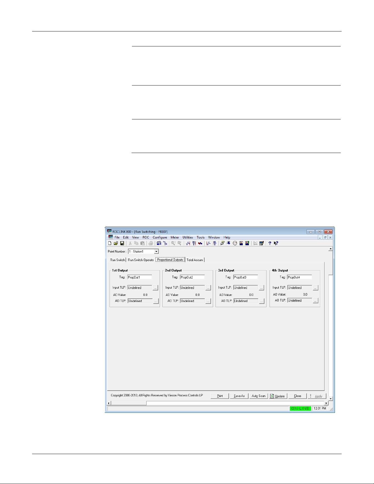
3.1.4. Run Switching – Proporti ona l Out put Ta b
Eight proportional outputs are available that send selected inputs points to
analog outputs. Station 1 contains the 1
contains the 5
th
to 8th output.
st
to 4th Output, while Station 2
Revised Aug-16 21
Figure 14. Run Switching screen – Proportional Outputs tab
1. Review the values in the following fields:
Page 26

Gas Control Manager Program User Manual (FB107)
Field
Description
Tag
Input TLP
AO Valu e
AO TLP
Use this field to name your output.
Selects the Input from available points on the ROC.
Shows the AO Value for the selected Output.
Selects the AO from available points on the ROC.
2. Click Apply to save your changes.
3. Proceed to Section 3.1.5, Run Switching – Total Accum Tab.
3.1.5. Run Switching – Total Accum Tab
The program provides four sets of resettable total accumulators for each
meter’s volume and energy. Unlike the total accumulator points in the
base FB107 (that roll over at a value of 1,000,000), this accumulator is
based on a huge data type that practically never rolls over unless manually
reset. All resets log to the event log. A station level reset from the Flow
Sum section reset these meter level accumulators that are associated with
that station.
22 Revised Aug-16
Figure 15. Run Switching screen – Total Accum tab
Page 27

Gas Control Manager Program User Manual (FB107)
Field
Description
1. Review the values in the following fields:
Volume (MCF)
Energy
(MMBTU)
Reset
2. Click Apply to save your changes.
3. Proceed to Section 3.1.6, About Open and Close DO.
This read-only field shows the Run Total Volume
Accum for the selected meter.
This read-only field shows the Run Total Volume
Energy for the selected meter.
Click to reset the value of the selected meter.
3.1.6. About Open and Close DO
The selected Solenoid Mode determines the DO parameter, so correct
selection of Status or Mode is not important. For testing purposes without
any physical I/O, FST MISC 1 to 4 Parameters are legitimate selections.
When using the Solenoid Mode Dual Solenoid Momentary, you configure
the pulse DO Time On delay in seconds using the ROCLINK I/O Discrete
Output screen’s General tab:
3.2. Cause and Effect
Revised Aug-16 23
Figure 16. Discrete Output window
Before you begin configuring causes and effects, a little planning is
helpful. You may have up to eight effects triggered by one or more of the
Page 28
Gas Control Manager Program User Manual (FB107)
sixteen causes. For this reason, it is best to plan your effects first, and then
decide what triggers those effects.
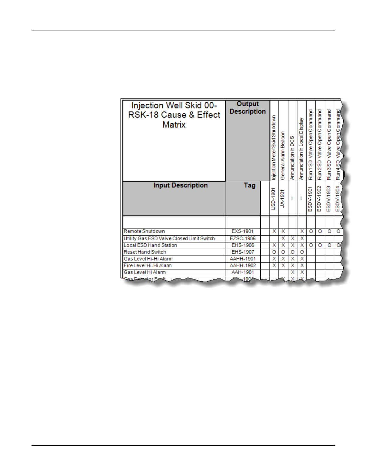
You may wish to use a chart such as the one pictured below as a handy
way to organize your information. The effects are located across the top of
the table in columns, and the causes are listed down the left side of the
table for easy reference:
Figure 17. Cause and Effect sample matrix
Appendix A provides a full sample matrix. Use the sample or make your
own design.
To start the Cause and Effect Program:
1. Double-click a FB107 or click the Direct Connect icon in the toolbar.
2. The device window opens. Click User Program > Gas Control Mgr
in the ROCLINK configuration tree.
3. Double-click Display #23, Effect Configuration.
4. A display appears for each effect point. Double-click an effect point to
see the Effect Configuration window for that station.
Each effect represents a particular action that occurs when the causes that
are linked to it are tripped or cleared. The Value When Active is the value
the program applies to the selected PtDef when the effect is active (1 =
24 Revised Aug-16
Page 29

Gas Control Manager Program User Manual (FB107)
Field
Description
Yes). The Value When Inactive is the value that the program applies to the
selected PtDef when the effect is not active (0 = No). The output state is
written either one time only or continuously based on the Assert Effect
Continuously selection. Writing one time to the output can be useful for
operations such as setting a discrete output momentary parameter for a
resettable output.
The Effect Configuration screen displays for the effect you have chosen.
The screen has three main sections:
Effect Configuration. Use this area to name your effect, define the
point and define the active and inactive states that will be applied.
Effect Usage. Use this area to define an effect to be a normal output or
hardware/software input reset point.
Effect Status. This area is informational.
3.2.1. Effect Configuration Se t t ings
Use this screen to configure the Effect Configuration settings..
Revised Aug-16 25
Figure 18. Effects Configuration screen
1. Review the values in the following fields:
Effect Tag
Use this field to name your effect with up to 10
characters. The default value is Effect 1.
Page 30

Gas Control Manager Program User Manual (FB107)
Field
Description
Enable Effect
PtDef
Tag and
CurValue
Value When
Active
Value When
Inactive
Force Value
When
Inactive
Select this checkbox to process the effect. If you leave
this checkbox blank, the program ignores the effect,
even when a cause should activate it (that is, one or
more causes that list the effect are true).
Indicates the controlled FB107 data point (TLP).
Shows the current name “PtDef” field whenever the
effect is activated by one or more true causes.
The user-specified (or dynamic) value that is sent to
the TLP defined in the “PtDef” field whenever the effect
is actuated by one or more true causes.
The user-specified (or dynamic) value that is sent to
the TLP defined in the Effect PtDef field whenever the
effect is un-activated as a result of no true cause. If the
Force Value When Inactive is unchecked, the TLP
defined in the Effect PtDef field is not controlled when
the effect is un-activated.
Writes the value in the Value When Inactive field to the
TLP defined in the PtDef field whenever the effect is
un-activated (that is, none of the causes that list the
effect are true).
If you leave this checkbox blank, the program does not
write any values to the PtDef field when the effect is
un-activated.
Assert Effect
Continuously
Effect Usage
Normal (Not
Hard-Wired
Software
Select this checkbox to have the program continuously
write active or inactive values to the PtDef TLP. This
may be desirable to assure that the output is reasserted to the expected state (for example, when a
DO point is taken out of manual mode).
If you leave this checkbox blank, the program sets the
state one time. This may be useful for a DO point in
momentary mode which resets itself.
Allows effects to be defined as reset points. Reset
points are monitored by causes that require a reset
before clearing from the tripped condition.
Select if the effect is handled like any
used as a
reset)
Reset (DI
Point)
Reset
other normal effect (this is the
default).
Select if the effect is handled as a
reset point requiring a manual action,
such as pressing a reset pushbutton.
Select if the effect is handled as a
reset point that can be reset through
a variable. This variable could then
be assigned to the LCD display or set
by SCADA. The program
automatically reset the field back to
the Inactive Value. The program now
allows the selection of other data
types besides unsigned integer
(UINT8).
26 Revised Aug-16
Page 31

Gas Control Manager Program User Manual (FB107)
Field
Description
Reset Code
Effect Status
Active Link
Tattletale
Current
Active Link
Count
Defines a code that, if matched to a Cause Reset
Code, reset those causes when the program detects a
software or hard-wired reset point.
Shows whether the effect has been tripped (activated).
Shows the first four causes that currently hold this
effect active, and the order in which they occurred.
Shows how many causes currently activate this effect.
2. Click Apply to save your changes.
3. Proceed to Section 3.2.2, Cause Configuration Settings.
A reset point is normally a digital input point, such as a status point. For
example, you may have the “PtDef” configured to be a DI status and the
“Actuated Value” would be the value of the digital input when the reset
button is pushed. All causes that require resets (“Require Reset?” Is
checked) would examine this effect (reset effect) for the activated value.
Causes reset when program detects the activated value.
3.2.2. Cause Configuration Set t ings
To access the Cause Configuration window:
1. Double-click a FB107 or click the Direct Connect icon in the toolbar.
2. The device window opens. Click User Program > Gas Control Mgr
in the ROCLINK configuration tree.
3. Double-click Display #22, Cause Configuration.
4. A display for each cause point appears. Double-click a cause point to
see the Cause Configuration window for that station.
Revised Aug-16 27
Page 32

Gas Control Manager Program User Manual (FB107)
Figure 19. Cause Configuration screen
The Cause Configuration window has seven main sections:
General Cause Configuration. Use this section to assign a name to
your cause, define it as simple or compound, indicate the requirement
for a pre- condition, and enable the cause.
Cause Execution Pre-Condition. This section displays only if you
select Pre-Condition Required in the General Cause Configuration
section. Use this section to define the pre-condition.
Primary Logic Section. Use this section to define the primary logic of
your cause.
Secondary Logic Section. This section displays only if you select
Compound in the General Cause Configuration section. Use this
section to define the secondary logic of your cause.
Effect Assignments. Use this section to link your cause to one or
more effects.
Misc Parameters. Use this section to write logs or alerts, or to have
this cause require a reset.
Cause Status. This informational section shows the status of the
cause. Red indicates tripped, and green indicates not tripped.
Causes can be configured to perform multiple functions, including
true/false logical comparisons, math functions, copying data, state
28 Revised Aug-16
Page 33

Gas Control Manager Program User Manual (FB107)
Field
Description
changes, and watchdog timer. Causes can be linked to eight effects, which
will activate when the cause comparison is true.
1. Review the values in the following fields:
General
Cause
Configuration
Cause
Simple/
Secondary’s
Pre-Condition
Cause Tag
Enabled
Compound
Relationship
with Primary
Required
A 10- character field for the tag from the
cause & effect matrix or a user-selected
tag.
Processes the cause. Leave the checkbox
blank to ignore the cause.
Note: Ensure all portions of the cause
screen are correctly configured
before enabling the cause.
Choose Simple if you want to use one
logic section in this cause. Choose
Compound to use two logic sections,
primary and secondary.
Sets the relationship between the primary
and secondary logic sections.
Note: This section displays only if you
chose Compound for this cause.
The relationship can be "AND" or
"OR".
Select this checkbox to activate this
cause only when the pre-condition has
been met. The Cause Execution PreCondition section displa ys when you
select this option.
Cause
Execution
Pre-Condition
PtDef
Operators
SetPt
Delay Secs.
Primary Logic
Section
Pre-Condition
Met
Preset
“Primary” refers to the fact that this field is in “Part 1” of the
two possible comparisons for each cause.
When the pre-condition goes true, this
box is checked.
Indicates the data point (TLP) value used
as a pre-condition. If the set point is not
reached for this TLP, this cause does not
activate.
Choose how you want the value of this
point to be evaluated – equal (==), greater
than or equal to (>=), not equal (!=), or
less than or equal to (<=).
Identifies the point at which the cause is
activated.
Identifies how long the program waits
after the condition is met before activating
the cause.
Revised Aug-16 29
Page 34

Gas Control Manager Program User Manual (FB107)
Field
Description
PtDef
Tag
Cur Value
Operator
The data point (TLP) value that displays in
the Cur Value field. This item can be any
numerical point including values from other
causes. Click the “…” button to the right of
the field to browse through the list of
available parameter s . You m ust configur e
this field for all cause function types.
The name given to the soft point in the soft
point configuration screen.
Note: The system reads the tag when you
configure the point definition. If you
change the tag after it has been read,
you will not see the updated tag name
until you reconfigure the point
definition. To force an update, set the
PtDef to “Undefined” then reset it to
the desired point. The tag name will
then be read and updated. If a
particular point type selected does not
have a tag as the first parameter, this
field may not display properly.
Displays the current value of the ROC point
(TLP) specified in the “PtDef” field.
Specifies the function (operator) of the
cause. The possible functions are shown in
Table 1.
SetPt Def
SetPt Value
Deadband
or Math
Result
Trip Delay Preset
Secs
The ROC data point (TLP) that becomes a
dynamic source of the set point value (“SetPt
Value” field). When this field is left
“Undefined,” you may enter a static value in
the “SetPt Val” field.
Holds the value that is used for comparisons
and math functions. This field is not used for
the One-Scan or Watchdog Timer functions.
If the “SetPt Def” field is configured (other
than “Undefined”), this field gets its value
from the TLP specified in “SetPt Def”.
This field serves three purposes. When
using comparison operators (>=, <=, ==, !=),
it specifies a Deadband value that must be
exceeded before an existing true
comparison can go false. For math
functions (Add, Subtract, Multiply, Divide),
this field holds the result of the math
operation. For the Copy Data function, this
field defines how many fields or parameters
to copy. Deadband is not used with OneScan or Watchdog Timer functions.
The number of user-defined seconds for
which the comparison must be true before
the cause goes true.
30 Revised Aug-16
Page 35

Gas Control Manager Program User Manual (FB107)
Field
Description
Elapsed
Secs
Timer
Timing
Secondary
Logic Section
Effect
Assignments
# Links
The Secondary Logic section has the same fields and logic
as the Primary Logic section.
These are the links to the effects for this cause. The link
labels indicate there are 8 possible links that can be used.
The Link fields will be the 1 to 8 number referenced to one
or more effects where 0 indicates no link. For example, If
you wanted the first effect activated to be effect #4, you
would enter 4 in the “# of Link 1” field. Any number of
effects can be listed here, from zero to eight. If all eight
fields are set to zero (defaults), no effects are connected to
the cause.
Currently
Active
Displays the delay count in seconds up to
the user-defined preset. When the
comparison becomes true, the count
(seconds) increments until it reaches the
“Preset Secs” and the cause becomes true.
If at anytime the comparison turns false, the
count resets to zero and the cause becomes
false.
This field’s value is 1 or 0. It serves as an
indication that the timer has been activated.
This shows the number of effects that are
currently tripped for this cause.
Misc
Parameters
Log Clears
Require
Log Trips
Reset?
Determines if an alarm generated by the
cause will be written to the ROC’s alarm
log. If this field is checked, every time the
cause goes true an alarm will be logged.
The log consists of the cause’s 10character tag and the value of “Cur Value”
along with the date and time.
Determines whether an entry will be
written to the ROC’s alarm log when this
cause is cleared. If this field is checked,
every time the cause is cleared an entry
will be logged. The log consists of the
cause’s 10-character tag and the value of
“Cur Value” along with the date and time.
Note: Log entries that begin with a “Z” as
the first digit are cause entries.
Alarms not generated by Cause &
Effect are not prefixed with a Z.
Check this box if the logic requires that a
reset button needs to be pushed before
the cause is set back to false. A reset can
be a hardware or software reset. For
example: when the cause goes true, it
actuates effects that cause a shutdown,
and it is desired that the shutdown be
maintained until a reset is done.
Revised Aug-16 31
Page 36

Gas Control Manager Program User Manual (FB107)
Field
Description
Reset Code
Minimum Trip
Secs. Preset
Elaps Trip
Secs
Accumulated
Trips
Cause Status Pre-Condition
Met
Primary
Section
Tripped
Secondary
Section
Tripped
Cause
Tripped
A numeric value that must be associated
with the Effect Reset Code that will
provide the reset through a DI point or
software point.
Holds the trip state for a minimum time so
a short duration trip can be detected.
Shows how long the cause has been
tripped. This is also the counter for the
Minimum Trip Secs Preset
Shows how many times the cause has
been tripped.
Shows whether the Pre-Condition section
has been tripped (1 for Yes, 0 for No).
Shows whether the Primar y section has
been tripped (1 for Yes, 0 for No).
Shows whether the Secondary section
has been tripped (1 for Yes, 0 for No).
Shows whether the cause has been
tripped (1 for Yes, 0 for No). If this is a
compound cause and the relationship
between primary and secondar y was set
to AND, the cause will only be tripped if
both the Primary Section and Secondary
Sections are tripped.
2. Click Apply to save your changes.
3. Proceed to Section 3.2.3, Cause and Effect Operate Display.
3.2.3. Cause and Effect Operate Display
The Cause & Effect Operate display is a read-only summary screen
showing all conditions, statistics and linkages for the 16 causes and 8
effects. Red indicates an active or tripped state where green indicates an
inactive or normal state.
32 Revised Aug-16
Page 37

Gas Control Manager Program User Manual (FB107)
Function
Function Description
>=
True If (compare) Greater Than (or equal to)
==
True If (compare) Equal To
!=
True If (compare) Not Equal To
One-Scan Rising
One-Scan Rising (Cur Value, 0 to 1 transition = true)
One-Scan Falling
One-Scan Falling (Cur Value, 1 to 0 transition = true)
Watchdog Timer
Watchdog Timer (resets on changing value of Cur Value)
Copy Data
Copies from Cur Value to SetPt Value (see full explanation
Add
Addition, Cur Value plus SetPt Value
Multiply
Multiplication, Cur Value times SetPt Value
Divide
Division, Cur Value divided by SetPt Value
Figure 20. Cause and Effect Operate Display screen
3.2.4. Configuration Exampl e s
The possible functions are shown in the table below. All comparisons are
between “Cur Value” and “SetPt Value.”
Table 1. List of Functions
<= True If (compare) Less Than (or equal to)
Subtract Subtraction, CurValue minus SetPt Value
Modulus Modulus. Remainder of Integers: Cur Value / SetPt Value
Revised Aug-16 33
Page 38

Gas Control Manager Program User Manual (FB107)
Greater Than
The cause goes true when the value at “Cur Value” is greater than or
Less Than
The cause goes true when the value at “Cur Value” is less than or equal
Figure 21. Operator area in the Primary Logic Section
The following examples show how to do configurations with each of the
available functions (operators). These examples do not show compound
logic (AND, OR) or examples utilizing enablers.
( > =)
equal to the value at “SetPt Val”.
Figure 22. Greater Than Operator example
This cause is true because “Cur Value” (831) is greater than “SetPt Val”
(800).
Note: Because of the deadband of 50, the cause will remain true until the
value of analog input A3 falls below 750.
( < =)
34 Revised Aug-16
to the value at “SetPt Value”.
Page 39

Gas Control Manager Program User Manual (FB107)
Equals
The cause goes true when the value at “Cur Value” is equal to the
Not Equal
The cause goes true when the value at “Cur Value” is not equal to the
Figure 23. Less Than Operator example
This cause is true because “Cur Value” (375) is less than or equal to
“SetPt Value” (385).
Note: “SetPt Value” is a dynamic value coming from analog input A3.
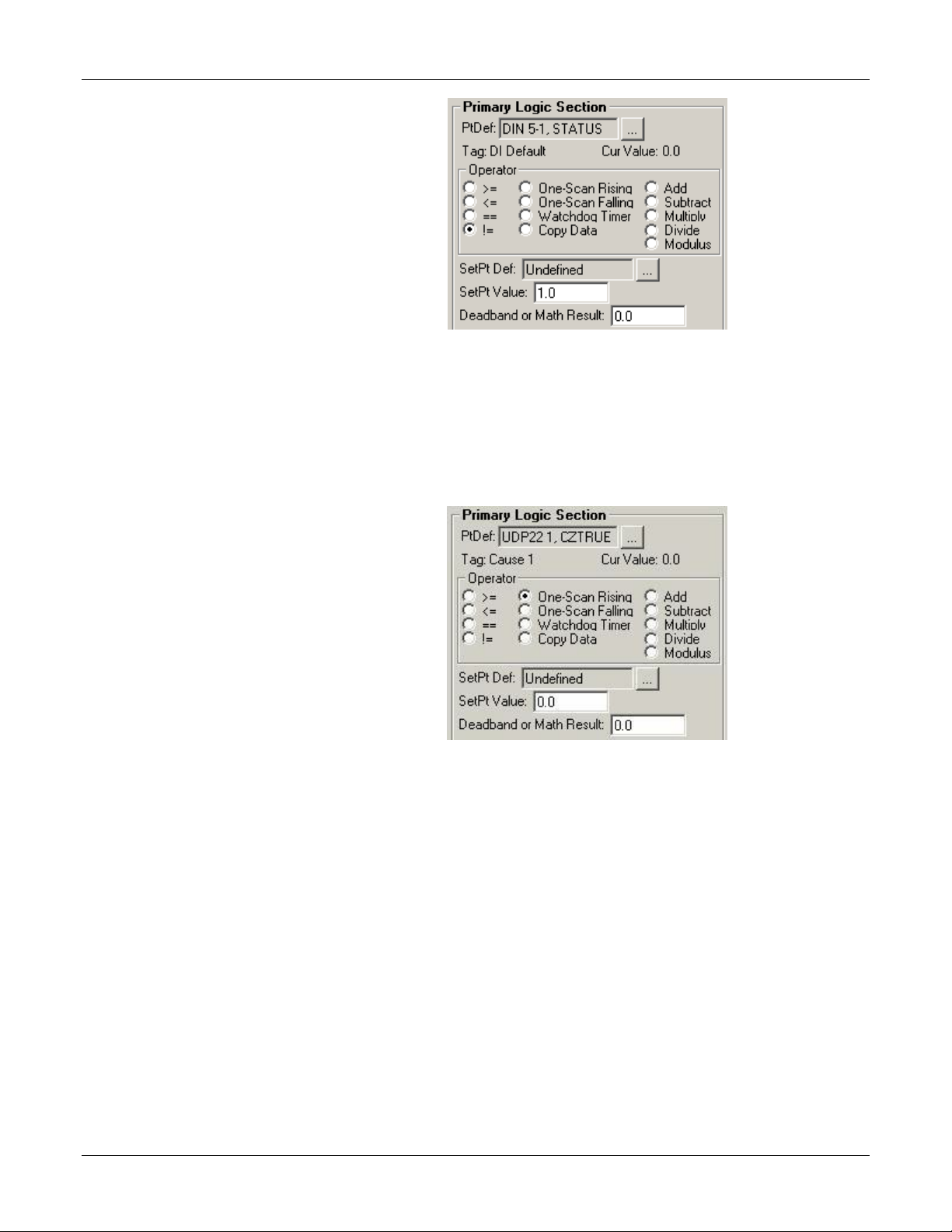
( = = )
value at “SetPt Value”.
Figure 24. Equals Operator example
This cause is true because digital input A9 is zero.
Note: Even when the level switch (A9) goes to normal (1) the cause
remains true until someone pushes the reset button if “Reset
Required?” is checked.
( ! = )
Revised Aug-16 35
value at “SetPt Value”.
Page 40
Gas Control Manager Program User Manual (FB107)
One-Scan Rising
The cause goes true when the value at “Cur Value” changes from zero
One-Scan Falling
The cause goes true when the value at “Cur Value” changes from one
Figure 25. Not Equal Operator example
This cause is true because the statue of digital input A9 (0) does not equal
the set point value (1).
to one. The cause will be true for one scan (1 second) only.
Figure 26. One-Scan Rising Operator example
The input to this cause is the status of cause #1 (true/false). When cause
#1 goes true, this cause will go true for one second. The effect for this
cause might be the mode of a digital output (versa valve or momentary
solenoid).
Inputs for this function should be limited to Boolean types because only a
zero to one transition will cause a trip.
to zero. The cause will be true for one scan (1 sec) only.
36 Revised Aug-16
Page 41

Gas Control Manager Program User Manual (FB107)
Watchdog Timer
The cause goes true when the value at “Cur Value” does not change
Figure 27. One-Scan Falling Operator example
The input to this cause is the status of cause #1 (true/false). When cause
#1 goes false, this cause will go true for one second. Effect #2 might be
the mode of a digital output (versa valve or momentary solenoid).
Inputs for this function should be limited to Boolean types because only a
one to zero transition will cause a trip.
within the time span defined at “True Delay sec”. This is an example
using the comm. port Valid Receive Counter to detect when
communication stops:
Figure 28. Watchdog Timer Operator example
The value (1053) is from the valid receipt-counter of a remote ROC. It is
stored in Soft Point #1 – Data #1.
The intent here is to alarm if there is no valid Modbus communication for
a 2-minute period. The effect this cause triggers might be a remote alarm
dialer channel.
Revised Aug-16 37
Page 42

Gas Control Manager Program User Manual (FB107)
Copy Data
The cause copies from Cur Value to SetPt Value. The numeric value in
the “Deadband” field tells the system what type of copy to make and
how much data to copy.
This is an example how to copy Orifice meter run parameters to
Softpoint data points.
Figure 29. Copy Data Operator example
The 1XX value in the Deadband/Result field commands that the copy is
from incremental parameters to incremental parameters, and is configured
38 Revised Aug-16
to copy 16 parameters (by parameter to parameter) starting from Orifice
Page 43

Gas Control Manager Program User Manual (FB107)
Add
The sum of “Cur Value” and “SetPt Value” is placed in the
Meter Run values #1, parameter 0 (flow rate per day). The 16 copied
items land in soft point #1, starting at DATA1 and ending at DATA16.
The Copy Data function copies data from “PtDef” to “SetPt Def.” There
are four different types of copies – by logicals, by parameters, logicals to
parameters, parameters to logicals. The numeric value in the “Deadband”
field tells the system what type of copy to make and how much data to
copy:
Table 2. Types of Copies
Number Copy Type Description
XX Logicals Source data located in a Logical order wil l be
copied to the Target data location in a Logical
order.
1XX Parameters Source data located in a Parameter order will
be copied to the Target data location in a
Parameter order.
2XX Logicals to
Parameters
3XX Parameters
to Logicals
Source data located in a Logical order will be
copied to the Target data location in a
Parameter order.
Source data located in a Param eter order will
be copied to the Target data location in a
Logical order.
Example: 105 in the Deadband field means copy parameters 0 through 4 to
parameters 1 through 5 on another TLP.
“Deadband/Result” register. If the SetPt Def is undefined, the value
entered in SetPt Value will be added as a constant. The cause status is
always zero.
Note: No effects are used with math operations.
Revised Aug-16 39
Figure 30. Add Operator example
Page 44
Gas Control Manager Program User Manual (FB107)
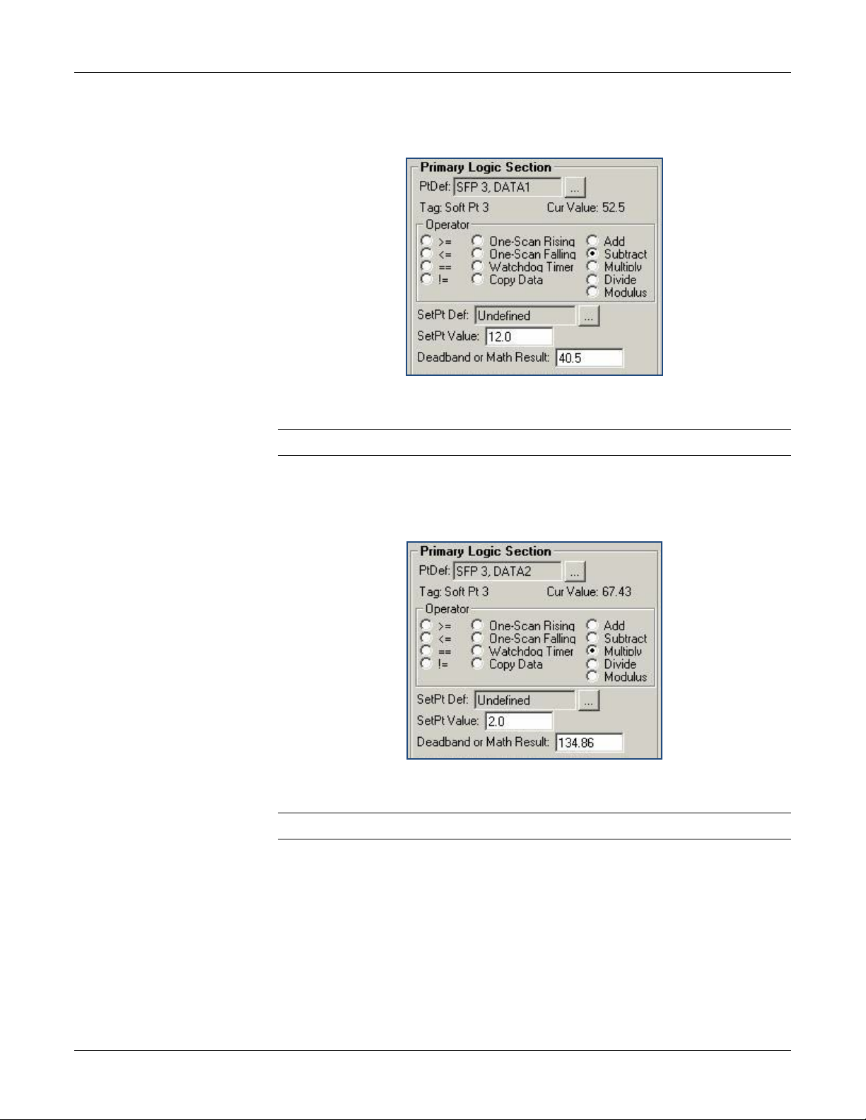
Subtract
The difference of “Cur Value” and “SetPt Value” is placed in the
Mutiply
The product of “Cur Value” and “SetPt Value” is placed in the
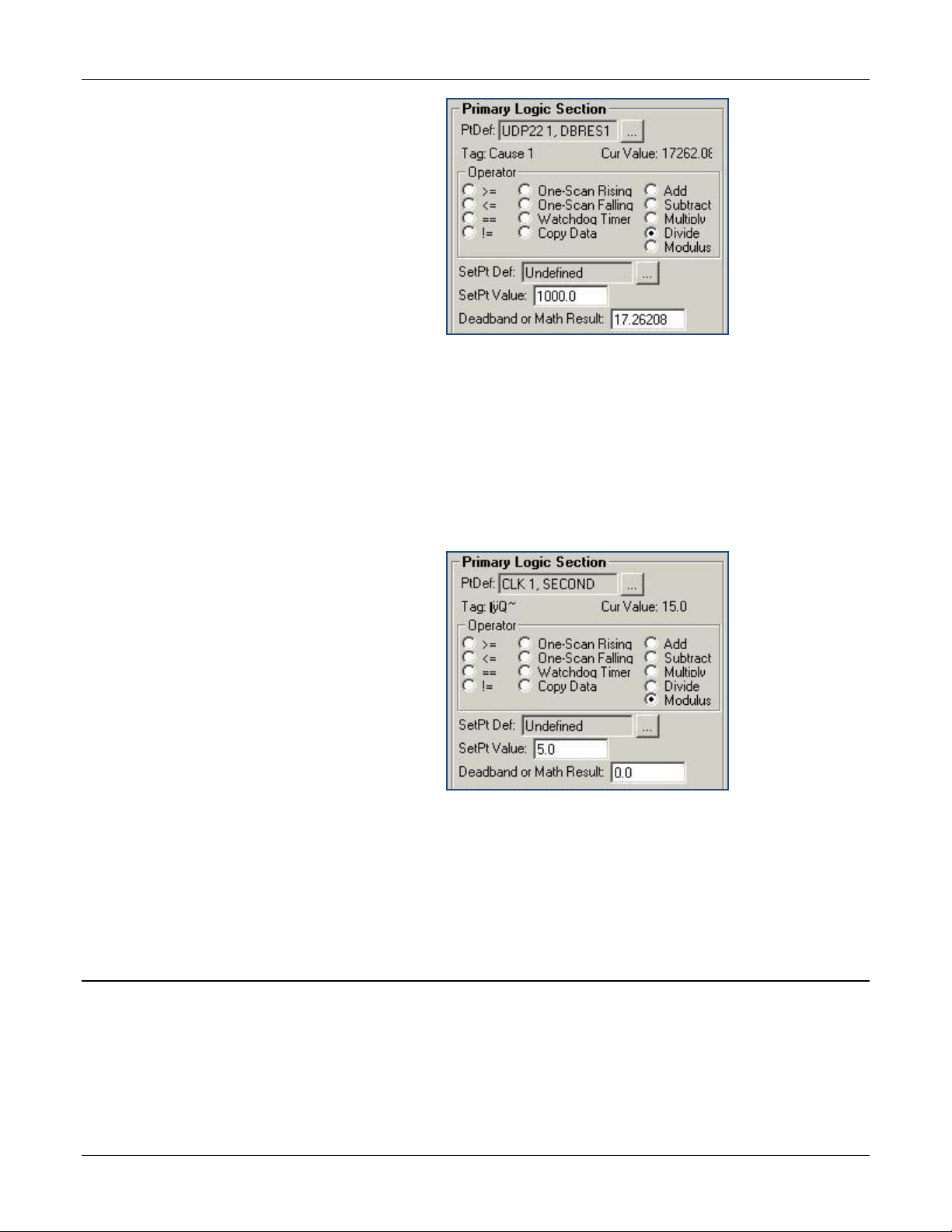
Divide
The quotient of “Cur Value” divided by “SetPt Value” is placed in the
“Deadband/Result” register. The cause status is always zero.
Figure 31. Subtract Operator example
Note: No effects are used with math operations.
“Deadband/Result” register. The cause status is always zero.
Figure 32. Multiply Operator example
Note: No effects are used with math operations.
“Deadband/Result” register. The cause status is always zero.
40 Revised Aug-16
Page 45
Gas Control Manager Program User Manual (FB107)
Modulus
The remainder of the integer division of “Cur Value” divided by “SetPt
Figure 33. Divide Operator example
The quotient of “Cur Value” divided by “SetPt Value” is placed in the
“Deadband/Result” register. The cause status is always zero.
Value” is placed in the “Deadband/Result” register. The cause status is
always zero. This is an example how to create 5-second execution from
ROC clock seconds:
Figure 34. Modulus Operator example
The seconds from the ROC clock are divided by five. Every five seconds
the modulus (remainder) is zero. Another cause can look at this cause’s
result field for a zero as part of condition for taking action. In this way a 5second execution clock is created.
3.3. Flow Summation
To start the Flow Summation Program:
1. Double-click a ROC device or click the Direct Connect icon in the
toolbar.
2. The device window will open. Click User Program > Gas Control
Mgr in the ROCLINK configuration tree.
Revised Aug-16 41
Page 46
Gas Control Manager Program User Manual (FB107)
Field
Description
Station
3. Double-click Display #36, Flow Sum.
4. You will see a display for each station. Double-click a station to see
the Flow Sum window for that station.
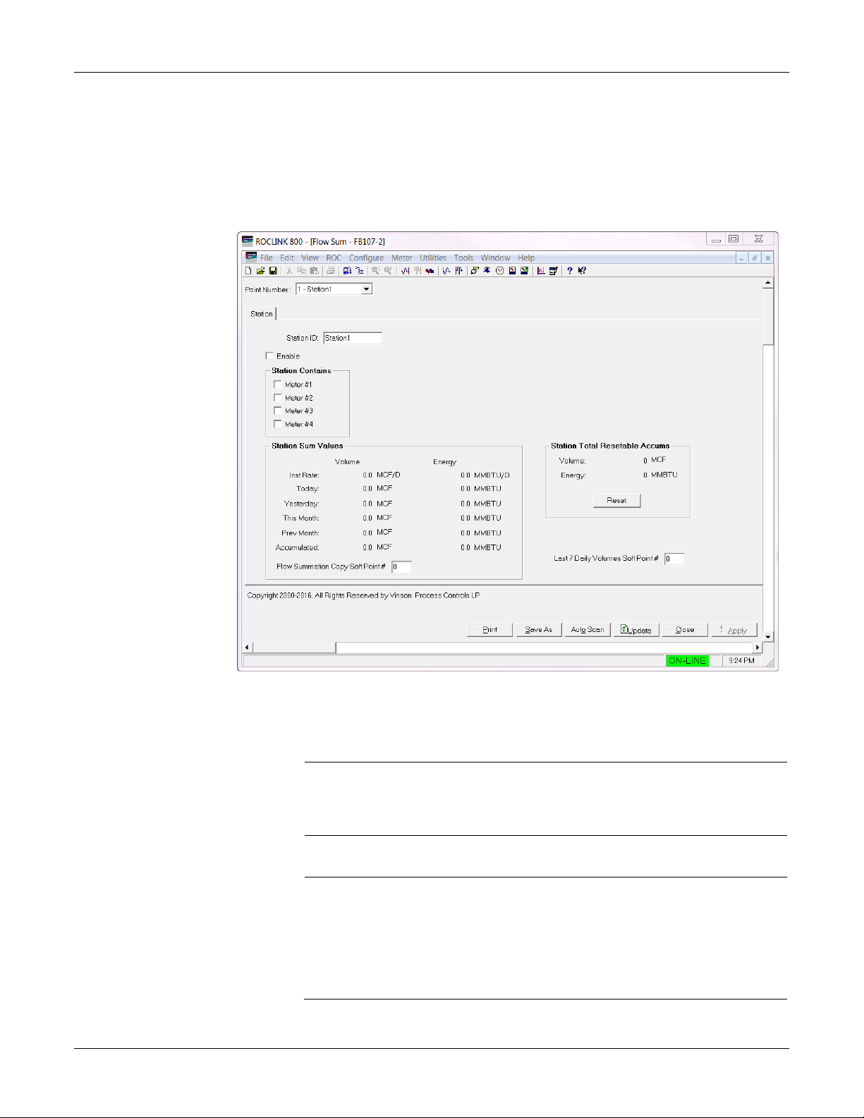
3.3.1. Flow Sum
The Flow Sum fields are described below:
Figure 35. Flow Sum screen
1. Review the values in the following fields:
Enable
Summation
Contains
Station Sum
values
42 Revised Aug-16
If you check Enable Summation, the program looks at
the following four fields and uses the ones that are
checked as a factor in the flow sum. If this field is not
checked, the remainder of this section is ignored.
Checks each meter to be added to the flow
summation.
Inst Rate
The sum of volume and energy
flow rates for all the meters
selected above. The units of the
volume flow rates are in MSCF or
M3 per day. The units of the energy
flow rates are in MMBTU or GJ per
day.
Page 47

Gas Control Manager Program User Manual (FB107)
Field
Description
Today
Yesterday
This Month
Prev Month
The sum of volume and energy
accumulated today for all of the
meters selected above. The units
of the volume are in MCF or M3.
The units of the energ y are in
MMBTU or GJ.
The sum of volume and energy
accumulated yesterday (the 24
hours before the last contract hour)
for all the meters s elec ted abo ve.
The units of the volume are in MCF
or M3. The units of the energy are
in MMBTU or GJ.
The sum of volume and energy
accumulated this month (month to
date) for all of the meters selected
above. The units of the volume are
in MCF or M3. The units of the
energy are in MMBTU or GJ. The
values are taken from the “Extra
Run Parameters” field of each
meter.
The sum of volume and energy
accumulated during the previous
month for all of the meters selected
above. The units of the volume are
in MCF or M3. The units of the
energy are in MMBTU or GJ. The
values are taken from the “Extra
Run Parameters” field of each
meter.
Accumulated
Flow
Summation
Copy Soft Point
#
Revised Aug-16 43
Specifies the softpoint where all of the meter values
are copied. The values are written to an alternate
place to make the data accessible because some
SCADA hosts might not be able to access userdefined point types (type 36). The program ignores
this field if the value is less than one (default=0) or
greater than thirty-two. The six flow values are placed
at Data1 through Data6. The equivalent “Energy”
values (rate through previous month accumulation) are
placed at Data7 through Data12. The energy fields are
in MMBTU.
The on-going accumulation of
volume and energy calculated by
the program, which do not reset
upon the change of the day or
month. These values increase
every second during flowing
conditions as an accumulation is
calculated from the flowrate. When
this accumulated value reaches
“interval” value, the program resets
the accumulation to zero.
Page 48

Gas Control Manager Program User Manual (FB107)
Field
Description
Last 7 Daily
Volumes Soft
Point #
2. Click Apply to save your changes.
3.3.2. Examples
Softpoints assignments are given below:
Softpoint Assignments – (Example: Starting at Softpoint 11)
Softpoint 11
Softpoint 12
Softpoint 13
Softpoint 14
Softpoint 15
This function is active when the field is set to a
number greater than zero. There is only one field for
this function. It uses two softpoints for every enabled
calculation for a maximum of eight softpoints. The
previous seven-day’s daily flow and energy totals for
each meter are written to the softpoints at each
contract hour. The data is organized as per
Table 4.
Table 3. Softpoint Assignments
Meter 1 Daily Accumulated Flow
Meter 1 Daily Accumulated Energ y
Meter 2 Daily Accumulated Flow
Meter 2 Daily Accumulated Energ y
Meter 3 Daily Accumulated Flow
Table 3 and
Softpoint 16
Softpoint 17
Softpoint 18
Meter 3 Daily Accumulated Energ y
Meter 4 Daily Accumulated Flow
Meter 4 Daily Accumulated Energ y
Each softpoint contains seven days of flow information along with
timestamps.
Table 4. Data point assignments
Data Point Assignments
Data1 Sunday’s Value Data11 Sunday’s Timestamp
Data2 Monday’s Value Data12 Monday’s Timestamp
Data3 Tuesday’s Value Data13 Tuesday’s Timestamp
Data4 Wednesday’s Value Data14 Wednesday’s Timestamp
Data5 Thursday’s Value Data15 Thursday’s Timestamp
Data6 Friday’s Value Data16 Friday’s Timestamp
Data7 Saturday’s Value Data17 Saturday’s Timestamp
The day-of-the-week is the day on which the daily flow period started. For
instance, if the contract hour is at 9am, the value stamped down at 9am on
Wednesday morning is listed at Data3 (Tuesday’s value).
44 Revised Aug-16
Page 49

Gas Control Manager Program User Manual (FB107)
Sample
The first three meters are selected. The flow totals from these three
meters are added together and displayed on the screen.
These totals are written to soft point #10.
Figure 36. Sample values
Flow data for the group is written to the designated soft point. The
numbers are placed into data points as described in the following table.
Table 5. Data Point Definitions
SOFTPOINT - DATA POINT DEFINITIONS
Data 1 Inst flow Data 7 Inst energy
Data 2 Today’s flow accum Data 8 Today’s energy accum
Data 3 Yesterday's flow accum Data 9 Yesterday's energy accum
Data 4 This month’s flow accum Data 10 This month’s energy accum
Data 5 Previous month’s low accum Data 11 Previous month’s energy accum
Data 6 Flow accumulated Data 12 Energy accumulated
Revised Aug-16 45
Page 50

Gas Control Manager Program User Manual (FB107)
Chapter 4 – Reference
This section provides information on the user-defined point type the Gas
Control Manager program uses:
Point Type 22: Cause Configuration
Point Type 23: Effect Configuration
Point Type 35: Run Switching
Point Type 36: Flow Sum
46 Revised Aug-16
Page 51

Gas Control Manager Program User Manual (FB107)
ag
4.1. Point Type 22: Cause Configurat ion
Point type 22 applies to Cause Configuration. There are 16 logicals of this point type.
Point Type 22: Cause Configuration
Parm Name Abbr Access System
or User
Update
0 Cause Tag PTTAG R/W User AC10 10 0x20 -> 0x7E
1 Enable Cause ENABLE R/W User UINT8 1 0 -> 1 0 1.00 Cause Enabled:
2 Input1 Definition INDEF1 R/W User TLP 3
3 Input1 Tag INTAG1 R/O System AC10 10 0x20 -> 0x7E
4 Cur Value1 CUVAL1 R/O System FL 4 Any
DataType Length Range Default Ver Description
for each
ASCII
character
for each
ASCII
character
FloatingPoint
Number
Cause 1 to
Cause16
17,0,2 1.00 Primary Logic Point Selection
<none> 1.00
0 1.00 Primary Logic Current Value:
1.00 Cause Tag Name
0 = Disable
1 = Enable
Selected Primary Logic PointT
ID
Revised Aug-16 47
Page 52

Gas Control Manager Program User Manual (FB107)
n
Point Type 22: Cause Configuration
Parm Name Abbr Access System
or User
Update
5 Function1 Type RELAT1 R/W User UINT8 1 1, 2, 3, 4, 5, 7,
6 SetPt1 Definition SETDEF R/W User TLP 3
7 SetPt1 Value SETPT1 R/W User FL 4
DataType Length Range Default Ver Description
8,10, 11, 12,
13,14, 18
Any
FloatingPoint
Number
1 1.00 Primary Logic Operator:
1) >=
2) <=
3) ==
4) !=
5) Watch Dog Timer
7) One Scan Rising
8) One Scan Falling
10) Add
11) Subtract
12) Multiply
13) Divide
14) Modulus
18) Copy Data
0,0,0 1.00 Primary Logic Set PointSelectio
0 1.00 Primary Logic Setpoint Value
8 Deadband orResult1 DBRES1 R/W Both FL 4 Any
FloatingPoint
Number
9 Part2 Enable USEPT2 R/W User UINT8 1 0 -> 1 0 1.00 Secondary Enable:
10 Input2 Definition INDEF2 R/W User TLP 3
11 Input2 Tag INTAG2 R/O System AC10 10 0x20 -> 0x7E
for each
ASCII
character
12 Cur Value2 CUVAL2 R/O System FL 4 Any 0 1.00 Secondary Logic Current Value
0 1.00 Primary Logic Deadband orMath
Result
0 = Simple
1 = Compound
0,0,0 1.00 Secondary Logic PointSelection
<none> 1.00 Selected Secondary LogicPoint
Tag ID
48 Revised Aug-16
Page 53

Point Type 22: Cause Configuration
FloatingPoint
Gas Control Manager Program User Manual (FB107)
Parm Name Abbr Access System
or User
Update
13 Function2 Type RELAT2 R/W User UINT8 1 1, 2, 3, 4, 5, 7,
14 SetPt2 Definition SETDF2 R/W User TLP 3
15 SetPt2 Value SETPT2 R/W User FL 4 Any
DataType Length Range Default Ver Description
Number
8,10, 11, 12,
13,14, 18
FloatingPoint
Number
1 1.00 Secondary Logic Operator:
1) >=
2) <=
3) ==
4) !=
5) Watch Dog Timer
7) One Scan Rising
8) One Scan Falling
10) Add
11) Subtract
12) Multiply
13) Divide
14) Modulus
18) Copy Data
0,0,0 1.00 Secondary Logic Set
PointSelection
0.0 1.00 Secondary Logic SetpointValue
16
17 And/Or Mode ANDOR R/W User UINT8 1 15 -> 16 15 1.00 Secondary Relationship
18 Cause Trip/Clear CZTRUE R/O System UINT8 1 0 -> 1 0 1.00 Cause Tripped Status:
Deadband orResult2
DBRES2 R/W Both FL 4
Any
FloatingPoint
Number
0.0 1.00
Secondary Logic Deadband
orMath Result
withPrimary:
15 = And with Primary
16 = Or with Primary
0 = No
Revised Aug-16 49
Page 54

Gas Control Manager Program User Manual (FB107)
1 = Yes
ag
Point Type 22: Cause Configuration
Parm Name Abbr Access System
or User
Update
19 Part1 Trip/Clear P1TRUE R/O System UINT8 1 0 -> 1 0 1.00 Primary Section TrippedStatus:
20 Part2 Trip/Clear P2TRUE R/O System UINT8 1 0 -> 1 0 1.00 Secondary Section
21 Use Digital Enabler ENABRQ R/W User UINT8 1 0 -> 1 0 1.00 Pre-Condition Required:
22 Digi Enab Definition ENADEF R/W User TLP 3
23 Digi Enab Tag ENATAG R/O System AC10 10 0x20 -> 0x7E
24 Digi Enab
ProcessValue
ENAPV R/O System FL 4 Any
DataType Length Range Default Ver Description
0 = No
1 = Yes
TrippedStatus:
0 = No
1 = Yes
0 = Disable
1 = Enable
0,0,0 1.00 Pre-Condition Point Selection
<none> 1.00
for each
ASCII
character
0.0 1.00 Pre-Condition Selected
FloatingPoint
Number
Selected Pre-Condition PointT
ID
PointValue
25 Digi Enabler Type ENAREL R/W User UINT8 1 0 -> 3 0 1.00 Pre-Condition Operator:
0) ==
1) !=
2) >=
3) <=
26 Digi Enab StPtValue ENSTPT R/W User FL 4 Any
FloatingPoint
Number
27 Digi Enab
ResultStatus
50 Revised Aug-16
ENARLT R/O System UINT8 1 0 -> 1 0 1.00 Pre-Condition Met:
0.0 1.00 Pre-Condition Setpoint
0 = No
1 = Yes
Page 55

Point Type 22: Cause Configuration
Gas Control Manager Program User Manual (FB107)
Parm Name Abbr Access System
or User
Update
28 Enab Delay
SecsPreset
29 Enab Delay
SecsElapsed
30 Pri Trip Delay
SecsPreset
31 Pri Trip Delay
SecsElapsed
32 Scan Interval SCANIV R/W User UINT8 1 0 -> 5 3 1.00 Scan Interval: (Not Used)
33 Log Alarms LOGALM R/W User UINT8 1 0 -> 1 0 1.00 Log Trips to Alarm Log:
ENAPRE R/W User UINT16 2 0 -> 65535 30 1.00 Pre-Condition Timer
ENACNT R/O System UINT16 2 0 -> 65535 0 1.00 Pre-Condition Timer (Secs)
TRPPR1 R/W User UINT16 2 0 -> 65535 0 1.00 Primary Logic Trip Preset(Secs)
TRPCT1 R/O System UINT16 2 0 -> 65535 0 1.00 Primary Logic Trip
DataType Length Range Default Ver Description
Preset(Secs)
Elapsed(Secs)
0 = 100 mSec
1 = 200 mSec
2 = 500 mSec
3 = 1 Sec
4 = 2 Sec
5 = 5 Sec
0 = No
1 = Yes
34 Require Reset RSTREQ R/W User UINT8 1 0 -> 1 0 1.00 Trip Requires Reset:
0 = No
1 = Yes
35 Effect 1 EFFT1 R/W User UINT8 1 1 -> 8 0 1.00 Effect Assignment Link 1
36 Effect 2 EFFT2 R/W User UINT8 1 1 -> 8 0 1.00 Effect Assignment Link 2
37 Effect 3 EFFT3 R/W User UINT8 1 1 -> 8 0 1.00 Effect Assignment Link 3
38 Effect 4 EFFT4 R/W User UINT8 1 1 -> 8 0 1.00 Effect Assignment Link 4
39 Effect 5 EFFT5 R/W User UINT8 1 1 -> 8 0 1.00 Effect Assignment Link 5
40 Effect 6 EFFT6 R/W User UINT8 1 1 -> 8 0 1.00 Effect Assignment Link 6
Revised Aug-16 51
Page 56

Gas Control Manager Program User Manual (FB107)
y
ets
counter, to validate the program ’s
Point Type 22: Cause Configuration
Parm Name Abbr Access System
or User
Update
41 Effect 7 EFFT7 R/W User UINT8 1 1 -> 8 0 1.00 Effect Assignment Link 7
42 Effect 8 EFFT8 R/W User UINT8 1 1 -> 8 0 1.00 Effect Assignment Link 8
43 Links Energized LNKENR R/O System UINT8 1 1 -> 8 0 1.00 Effect Assignment LinksCurrentl
44 Min Trip SecsPres
45 Min Trip
SecsElapsed
46 Log Clears LOGCLR R/W User UINT8 1 0 -> 1 0 1.00 Log Clears To Alarm Log:
47 Reset Code RSTCOD R/W User UINT8 1 0 -> 255 0 1.00 Reset Code Matched to
48 Sec Trip DelaySecs
Preset
49 Sec Trip DelaySecs
Elapsed
50 Pri Trip DelayTimer
Timing
MNTPRE R/W User UINT16 2 0 -> 65535 0 1.00 Minimum Trip Seconds Preset
MNTCNT R/O System UINT16 2 0 -> 65535 0 1.00 Minimum Trip SecondsElapsed
TRPPR2 R/W User UINT16 2 0 -> 65535 0 1.00 Secondary Logic Trip
TRPCT2 R/O System UINT16 2 0 -> 65535 0 1.00 Secondary Logic Trip
TMRTT1 R/O System UINT8 1 0 -> 1 0 1.00 Primary Logic Trip TimerTiming:
DataType Length Range Default Ver Description
Active
0 = No
1 = Yes
EffectReset Code
Preset(Secs)
Elapsed(Secs)
0 = Timer Expired
1 = Timing
51 Sec Trip DelayTimer
Timing
52 Accumulated Trips TRPACM R/W Both UINT16 2 0 -> 65535 0 1.00 Accumulated Trips
53 Watchdog Timer WATDOG R/O SYSTEM UINT16 2 0 -> 65535 0 3.05 Provides an incrementing
52 Revised Aug-16
TMRTT2 R/O System UINT8 1 0 -> 1 0 1.00 Secondary Logic Trip
TimerTiming:
0 = Timer Expired
1 = Timing
running status.
Only updated for the first logical
instance.
Page 57

Gas Control Manager Program User Manual (FB107)
Update
2
Effect Definition
EFFDEF
R/W
User
TLP
3 0,0,0
1.00
Point Selection
Number
NotActive
Number
4.2. Point Type 23: Effect Configur a ti on
Point type 23 applies to Effect Configuration. There are up to 8 logicals of this point type.
Point Type 23: Effect Configuration
Par m Name Abbr Access
0 Effect Tag EFFTAG R/W User AC10 10
1 Effect Enable EFFENB R/W User UINT8 1 0 -> 1 0 1.00 Effect Enable:
3 Definition Tag DEFTAG R/O System AC10 10 0x20 -> 0x7E for
4 Now Active CURENG R/O System UINT8 1 0 -> 1 0 1.00 Effect Status Is Active:
5 Cur Val CURVAL R/O System FL 4 Any FloatingPoint
6 Value When Active ENGVAL R/W User FL 4 Any FloatingPoint
7
Value When
UENVAL R/W User FL 4
System
or User
DataType Length Range Default Ver Description
0x20 -> 0x7E for
each ASCII
character
each ASCII
character
Number
Any FloatingPoint
Effect 1 to
Effect16
<none> 1.00 Selected Point Tag ID
0.0 1.00 Effect Current Value
1.0 1.00 Value When Active
0.0 1.00 Value When Inactive
1.00 Effect Tag Name
0 = Disabled
1 = Enabled
0 = No
1 = Yes
8
9 Is Reset Pt? RESTPT R/W User UINT8 1 0 -> 2 0 1.00 Reset Type:
Revised Aug-16 53
Apply When
NotActive
WRITEU R/W User UINT8 1 0 -> 1 1 1.00 Force Value When Inactive:
0 = No
1 = Yes
0 = This Point is Not a
ResetPoint
1 = This Point is a HardWiredReset
Page 58

Gas Control Manager Program User Manual (FB107)
Update
2 = This Point is a
Point Type 23: Effect Configuration
Par m Name Abbr Access
10 1st Out Cause 1OUTCZ R/O System UINT8 1 0 -> 1 0 1.00 1st Trip Cause
11 2nd Out Cause 2OUTCZ R/O System UINT8 1 0 -> 1 0 1.00 2nd Trip Cause
12 3rd Out Cause 3OUTCZ R/O System UINT8 1 0 -> 1 0 1.00 3rd Trip Cause
13 4th Out Cause 4OUTCZ R/O System UINT8 1 0 -> 1 0 1.00 4th Trip Cause
System
or User
DataType Length Range Default Ver Description
SoftwareReset
NumberTattletale:
0 = None
1 = Active
NumberTattletale:
0 = None
1 = Active
NumberTattletale:
0 = None
1 = Active
NumberTattletale:
0 = None
1 = Active
14 1st Out Tag 1OTTAG R/O System AC10 10
15 2nd Out Tag 2OTTAG R/O System AC10 10
16 3rd Out Tag 3OTTAG R/O System AC10 10 0x20 -> 0x7E for
54 Revised Aug-16
0x20 -> 0x7E for
each ASCII
character
0x20 -> 0x7E for
each ASCII
character
each ASCII
character
<none> 1.00 1st Trip Cause Tag
<none> 1.00 2nd Trip Cause Tag
<none> 1.00 3rd Trip Cause Tag
Page 59

Point Type 23: Effect Configuration
Update
19
Active Link Count
LNKCNT
R/O
System
UINT8
1
1 -> 16
0
1.00
Current Active Link Count
y
Gas Control Manager Program User Manual (FB107)
Par m Name Abbr Access
17 4th Out Tag 4OTTAG R/O System AC10 10 0x20 -> 0x7E for
18 Reset Code RSTCOD R/W User UINT8 1 0 -> 255 0 1.00 Match Reset Code with
20 Assert
EffectContinuousl
EFMODE R/W User UINT8 1 0 -> 1 0 3.03 Assert Effect Continuously:
System
or User
DataType Length Range Default Ver Description
<none> 1.00 4th Trip Cause Tag
each ASCII
character
CauseReset Code
0 = Once
1 = Continuous
Revised Aug-16 55
Page 60

Gas Control Manager Program User Manual (FB107)
4.3. Point Type 35: Run Switching
Point type 35 applies to Run Switching. There are two logicals of this point type.
Point Type 35: Run Switching
Parm Name Abbr Access System
or User
Update
0 Station Tag STATAG R/W User AC10 10 0x20 ->
1 Run1 Tag RUN1TG R/W User AC10 10 0x20 ->
2 Run2 Tag RUN2TG R/W User AC10 10
3 Run3 Tag RUN3TG R/W User AC10 10 0x20 ->
4 Run4 Tag RUN4TG R/W User AC10 10 0x20 ->
5 Run1 Enable RUN1EN R/W User UINT8 1 0 -> 1 1 1.00 Run 1 Enable:
6 Run2 Enable RUN2EN R/W User UINT8 1 0 -> 1 0 1.00 Run 2 Enable:
7 Run3 Enable RUN3EN R/W User UINT8 1 0 -> 1 0 1.00 Run 3 Enable:
DataType
Length Range Default Ver Description
0x7E for
each ASCII
character
0x7E for
each ASCII
character
0x20 ->
0x7E for
each ASCII
character
0x7E for
each ASCII
character
0x7E for
each ASCII
character
Station1
to
Station4
Run1 1.00 Run 1 Tag Name
Run2 1.00 Run 2 Tag Name
Run3 1.00 Run 3 Tag Name
Run4 1.00 Run 4 Tag Name
1.00 Station Tag Name
0 = Disabled
1 = Enabled
0 = Disabled
1 = Enabled
0 = Disabled
1 = Enabled
56 Revised Aug-16
Page 61

Gas Control Manager Program User Manual (FB107)
Point Type 35: Run Switching
Parm Name Abbr Access System
or User
Update
8 Run4 Enable RUN4EN R/W User UINT8 1 0 -> 1 0 1.00 Run 4 Enable:
9 Run1 Input R1INPT R/W User TLP 3
10 Run2 Input R2INPT R/W User TLP 3
11 Run3 Input R3INPT R/W User TLP 3
12 Run4 Input R4INPT R/W User TLP 3
13 Run1 Open DO R1OPDO R/W User TLP 3
14 Run2 Open DO R2OPDO R/W User TLP 3
15 Run3 Open DO R3OPDO R/W User TLP 3
16 Run4 Open DO R4OPDO R/W User TLP 3
17 Run1 Close DO R1CLDO R/W User TLP 3
18 Run2 Close DO R2CLDO R/W User TLP 3
19 Run3 Close DO R3CLDO R/W User TLP 3
20 Run4 Close DO R4CLDO R/W User TLP 3
21 Run1 Open State R1OPST R/W System UINT8 1 0 -> 1 1 1.00 Run 1 Energize to Open:
22 Run2 Open State R2OPST R/W System UINT8 1 0 -> 1 1 1.00 Run 2 Energize to Open:
23 Run3 Open State R3OPST R/W System UINT8 1 0 -> 1 1 1.00 Run 3 Energize to Open:
24 Run4 Open State R4OPST R/W System UINT8 1 0 -> 1 1 1.00 Run 4 Energize to Open:
DataType
Length Range Default Ver Description
0 = Disabled
1 = Enabled
0,0,0 1.00 Selected Run 1 Input
0,0,0 1.00 Selected Run 2 Input
0,0,0 1.00 Selected Run 3 Input
0,0,0 1.00 Selected Run 4 Input
0,0,0 1.00 Selected Run 1 Open DO
0,0,0 1.00 Selected Run 2 Open DO
0,0,0 1.00 Selected Run 3 Open DO
0,0,0 1.00 Selected Run 4 Open DO
0,0,0 1.00 Selected Run 1 Close DO
0,0,0 1.00 Selected Run 2 Close DO
0,0,0 1.00 Selected Run 3 Close DO
0,0,0 1.00 Selected Run 4 Close DO
0 = No
1 = Yes
0 = No
1 = Yes
0 = No
1 = Yes
0 = No
1 = Yes
Revised Aug-16 57
Page 62

Gas Control Manager Program User Manual (FB107)
Point Type 35: Run Switching
Parm Name Abbr Access System
or User
Update
25 Run1 Lo SetPt R1LOSP R/W User FL 4 Any
26 Run2 Lo SetPt R2LOSP R/W User FL 4 Any
27 Run3 Lo SetPt R3LOSP R/W User FL 4 Any
28 Run4 Lo SetPt R4LOSP R/W User FL 4 Any
29 Run1 Hi SetPt R1HISP R/W User FL 4
DataType
Length Range Default Ver Description
FloatingPoint
Number
FloatingPoint
Number
FloatingPoint
Number
FloatingPoint
Number
Any
FloatingPoint
Number
0.0 1.00 Run 1 Low Set Point
10.0 1.00 Run 2 Low Set Point
10.0 1.00 Run 3 Low Set Point
10.0 1.00 Run 4 Low Set Point
200.0 1.00 Run 1 High Set Point
30 Run2 Hi SetPt R2HISP R/W User FL 4 Any
FloatingPoint
Number
31 Run3 Hi SetPt R3HISP R/W User FL 4 Any
FloatingPoint
Number
32 Run1 Leave Open R1LVOP R/W User UINT8 1 0 -> 1 1 1.00 Run 1 Leave Open AfterOpening
33 Run2 Leave Open R2LVOP R/W User UINT8 1 0 -> 1 1 1.00 Run 2 Leave Open AfterOpening
34 Run3 Leave Open R3LVOP R/W User UINT8 1 0 -> 1 1 1.00 Run 3 Leave Open AfterOpening
200.0 1.00 Run 2 High Set Point
200.0 1.00 Run 3 High Set Point
Next Tube
0 = No
1 = Yes
Next Tube
0 = No
1 = Yes
Next Tube
0 = No
1 = Yes
58 Revised Aug-16
Page 63

Gas Control Manager Program User Manual (FB107)
ds
ds
nts
Point Type 35: Run Switching
Parm Name Abbr Access System
or User
Update
35 Spike Delay SPKDLY R/W User UINT8 1 0 -> 255 5 1.00 Spike Delay For All Inputs -Secon
36 Settling Delay SETDLY R/W User UINT8 1 0 -> 255 30 1.00 Settling Run Switch Delay -Secon
37 Runs Open RNSOPN R/O System UINT8 1 1 -> 4 0 1.00 Runs Open Status
38 Control Type CTLTYP R/W User UINT8 1 0 -> 1 0 1.00 Switch Mode:
39 Prop1 Tag PR1TAG R/W User AC10 10
40 Prop2 Tag PR2TAG R/W User AC10 10 0x20 ->
41 Prop3 Tag PR3TAG R/W User AC10 10 0x20 ->
42 Prop4 Tag PR4TAG R/W User AC10 10
43 Prop1 Input PRP1IN R/W User TLP 3
44 Prop2 Input PRP2IN R/W User TLP 3
45 Prop3 Input PRP3IN R/W User TLP 3
46 Prop4 Input PRP4IN R/W User TLP 3
47 Prop1 Output PRP1OU R/W User TLP 3
48 Prop2 Output PRP2OU R/W User TLP 3
49 Prop3 Output PRP3OU R/W User TLP 3
DataType
Length Range Default Ver Description
0 = Monitor Last OpenedSwitch
Points
1 = Monitor All Passed SwitchPoi
0x20 ->
0x7E for
each ASCII
character
0x7E for
each ASCII
character
0x7E for
each ASCII
character
0x20 ->
0x7E for
each ASCII
character
PropOut1 1.00
PropOut2 1.00 Proportional Output 2 TagName
PropOut3 1.00 Proportional Output 3 TagName
PropOut4 1.00
0,0,0 1.00 Selected Input 1
0,0,0 1.00 Selected Input 2
0,0,0 1.00 Selected Input 3
0,0,0 1.00 Selected Input 4
0,0,0 1.00 Selected Proportional Output 1
0,0,0 1.00 Selected Proportional Output 2
0,0,0 1.00 Selected Proportional Output 3
Proportional Output 1 TagName
Proportional Output 4 TagName
Revised Aug-16 59
Page 64

Gas Control Manager Program User Manual (FB107)
Point Type 35: Run Switching
Parm Name Abbr Access System
or User
Update
50 Prop4 Output PRP4OU R/W User TLP 3
51 Run1 Open Close R1OPCL R/W Both UINT8 1 0 -> 1 0 1.00 Run 1 Status:
52 Run2 Open Close R2OPCL R/W Both UINT8 1 0 -> 1 0 1.00 Run 2 Status:
53 Run3 Open Close R3OPCL R/W Both UINT8 1 0 -> 1 0 1.00 Run 3 Status:
54 Run4 Open Close R4OPCL R/W Both UINT8 1 0 -> 1 0 1.00 Run 4 Status:
55 Use Flow Sensing FLWSNS R/W User UINT8 1 0 -> 2 0 3.00 Focus Run Verification:
56 ESD Pt Def ESDDEF R/W User TLP 3
DataType
Length Range Default Ver Description
0,0,0 1.00 Selected Proportional Output 4
0 = Close
1 = Open
0 = Close
1 = Open
0 = Close
1 = Open
0 = Close
1 = Open
0 = Disable
1 = PV Flow Sensing
2 = DI State
0,0,0 1.00
Selected ESD Point(Referenced
Point Monitored for ESD)
57 ESD Trip Value ESDTRP R/W User UINT8 1 0 -> 255 0 1.00 ESD Trip Set Point
58 ESD Cur Value ESDCUR R/O System UINT8 1 0 -> 1 0 1.00 ESD Status:
0 = OK to Run
1 = ESD Active
59 Run1 Input Value DP1VAL R/O System FL 4 Any
FloatingPoint
Number
60 Run2 Input Value DP2VAL R/O System FL 4 Any
FloatingPoint
Number
0.0 1.00 Run 1 Value
0.0 1.00 Run 2 Value
60 Revised Aug-16
Page 65

Gas Control Manager Program User Manual (FB107)
ds
Point Type 35: Run Switching
Parm Name Abbr Access System
or User
Update
61 Run3 Input Value DP3VAL R/O System FL 4 Any
62 Run4 Input Value DP4VAL R/O System FL 4 Any
63 Spike DelaySeconds SPKSEC R/O System UINT8 1 0 -> 255 0 1.00 Spike Delay - (Secs)
64 Settling DelaySecon
65 Trail Run
DelaySeconds
66 Focus Run Number FOCRUN R/O System UINT8 1 0 -> 3 0 1.00 Current Control Run:
67 Focus Sense PVCutoff FPVCUT R/W User FL 4 Any
68 Run Total
VolumeAccum 1
69
Run Total
VolumeAccum 2
STLSEC R/O System UINT8 1 0 -> 255 0 1.00 Settling Delay - (Secs)
TRLSEC R/O System UINT8 1 0 -> 255 0 1.00
RVOLA1 R/O System UINT32 4 0-
RVOLA2 R/O System UINT32 4 0-
DataType
Length Range Default Ver Description
0.0 1.00 Run 3 Value
FloatingPoint
Number
0.0 1.00 Run 4 Value
FloatingPoint
Number
Trail Run Delay (Secs). Used
when Close Prev Tube is
selected.
Run #1
Run #2
Run #3
Run #4
3.0 1.00 PV Low Cutoff for FlowSensing
FloatingPoint
Number
0 3.00 Run Total Volume Accum 1
>4294967295
0 3.00 Run Total Volume Accum 2
>4294967295
70 Run Total
VolumeAccum 3
71 Run Total
EnergyAccum 1
72 Run Total
EnergyAccum 2
73 Run Total
EnergyAccum 3
RVOLA3 R/O System UINT32 4 0-
RENEA1 R/O System UINT32 4 0-
RENEA2 R/O System UINT32 4 0-
RENEA3 R/O System UINT32 4 0-
0 3.00 Unused ROC800 Compatibility
>4294967295
0 3.00 Run Total Energy Accum 1
>4294967295
0 3.00 Run Total Energy Accum 2
>4294967295
0 3.00 Unused ROC800 Compatibility
>4294967295
Revised Aug-16 61
Page 66

Gas Control Manager Program User Manual (FB107)
Point Type 35: Run Switching
Parm Name Abbr Access System
or User
Update
74
Run Total
AccumReset 1
RARST1 R/W User UINT8 1 0->1 0 3.00
DataType
Length Range Default Ver Description
Run Total Accum Reset 1: 0
=Normal, 1 = Reset (program
returns to normal)
75 Run Total
AccumReset 2
76 Run Total
AccumReset 3
77
78 AGA
79 AGA
80 AO Value 1 AOVAL1 R/O System FL 4
81 AO Value 2 AOVAL2 R/O System FL 4 Any
82 AO Value 3 AOVAL3 R/O System FL 4 Any
83 AO Value 4 AOVAL4 R/O System FL 4
AGA
CalculationSelection 1
CalculationSelection 2
CalculationSelection 3
RARST2 R/W User UINT8 1 0->1 0 3.00
RARST3 R/W User UINT8 1 0->1 0 3.00 Unused ROC800 Compatibility
AGASL1 R/W User UINT8 1 0->1 0 3.00 Unused ROC800 Compatibility
AGASL2 R/W User UINT8 1 0->1 0 3.00 Unused ROC800 Compatibility
AGASL3 R/W User UINT8 1 0->1 0 3.00 Unused ROC800 Compatibility
Any
FloatingPoint
Number
FloatingPoint
Number
FloatingPoint
Number
Any
FloatingPoint
Number
Run Total Accum Reset 2: 0 =
Normal, 1 = Reset (program
returns to normal)
0 3.00 AO Value 1
0 3.00 AO Value 2
0 3.00 AO Value 3
0 3.00 AO Value 4
84 Status Code STATUS R/O System UINT8 1 0->18 0 3.00 Status Code:
0 = Status Ok
1 = Station ESD
2 = PV Type Not Selected
3 = Invalid Open DO Type
62 Revised Aug-16
Page 67

Point Type 35: Run Switching
4 = Invalid Open DO Param
Parm Name Abbr Access System
85 Failure Type FAILTY R/W User UINT8 1 0->2 0 3.00 Failure Type:
86 Failure Action FAIACT R/W User UINT8 1 0->2 0 3.00 Failure Action:
87 Failure Delay FAIDLY R/W User UINT8 1 0->255 0 3.00 Failure Delay (Secs)
88 Failure Seconds FAISEC R/O System UINT8 1 0->255 0 3.00 Failure Seconds
89 Solenoid Mode SOLMO D R/W User UINT8 1 0->3 0 3.00 Solenoid Mode:
or User
Update
DataType
Gas Control Manager Program User Manual (FB107)
Length Range Default Ver Description
5 = Invalid Close DO Type
6 = Invalid Close DO Param
7 = Invalid Open DI Type
8 = Invalid Open DI Param
9 = Invalid Close DI Type
10 = Invalid Close DI Param
11 = Illegal Flow Tube 1
12 = Illegal Flow Tube 2
13 = Illegal Flow Tube 3
14 = Illegal Flow Tube 4
15 = Illegal DI Tube 1
16 = Illegal DI Tube 2
17 = Illegal DI Tube 3
18 = Illegal DI Tube 4
0 = None
1 = Illegal PV Flow
2 = Illegal DI State
0 = Status Only
1 = Alarm Log + Status
2 = Disable Tube + Alarm Log+
Status
0 = Single Solenoid Latch
1 = Dual Solenoid Latch
2 = Dual Solenoid Latch - DIReset
Revised Aug-16 63
Page 68

Gas Control Manager Program User Manual (FB107)
3 = Dual Solenoid Momentary
Point Type 35: Run Switching
Parm Name Abbr Access System
or User
Update
DataType
Length Range Default Ver Description
90 Run 1 Open ResetDI R1OPDI R/W User TLP 3
91 Run 2 Open ResetDI R2OPDI R/W User TLP 3
92 Run 3 Open ResetDI R3OPDI R/W User TLP 3
93 Run 4 Open ResetDI R4OPDI R/W User TLP 3
94 Run 1 Close ResetDI R1CLDI R/W User TLP 3
95
96 Run 3 Close ResetDI R3CLDI R/W User TLP 3
97 Run 4 Close ResetDI R4CLDI R/W User TLP 3
98 Run 1 Open DI
99 Run 2 Open DI
100 Run 3 Open DI
101
102 Run 1 Close DI
103 Run 2 Close DI
104 Run 3 Close DI DICLV3 R/O System UINT8 1 0->1 0 3.00 Run 3 Close DI Value:
Run 2 Close ResetDI
Value
Value
Value
Run 4 Open DI
Value
Value
Value
R2CLDI R/W User TLP 3
DIOPV1 R/O System UINT8 1 0->1 0 3.00 Run 1 Open DI Value:
DIOPV2 R/O System UINT8 1 0->1 0 3.00 Run 2 Open DI Value:
DIOPV3 R/O System UINT8 1 0->1 0 3.00 Run 3 Open DI Value:
DIOPV4 R/O System UINT8 1 0->1 0 3.00 Run 4 Open DI Value:
DICLV1 R/O System UINT8 1 0->1 0 3.00 Run 1 Close DI Value:
DICLV2 R/O System UINT8 1 0->1 0 3.00 Run 2 Close DI Value:
0,0,0 3.00 Run 1 Open Reset DI
0,0,0 3.00 Run 2 Open Reset DI
0,0,0 3.00 Run 3 Open Reset DI
0,0,0 3.00 Run 4 Open Reset DI
0,0,0 3.00 Run 1 Close Reset DI
0,0,0 3.00 Run 2 Close Reset DI
0,0,0 3.00 Run 3 Close Reset DI
0,0,0 3.00 Run 4 Close Reset DI
0 = Reset
1 = Open
0 = Reset
1 = Open
0 = Reset
1 = Open
0 = Reset
1 = Open
0 = Reset
1 = Close
0 = Reset
1 = Close
64 Revised Aug-16
Page 69

Point Type 35: Run Switching
Value
0 = Reset
Parm Name Abbr Access System
or User
Update
105
Run 4 Close DI
Value
DICLV4 R/O System UINT8 1 0->1 0 3.00 Run 4 Close DI Value:
DataType
Gas Control Manager Program User Manual (FB107)
Length Range Default Ver Description
1 = Close
0 = Reset
1 = Close
Revised Aug-16 65
Page 70

Gas Control Manager Program User Manual (FB107)
4.4. Point Type 36: Flow Sum
Point type 36 applies to Flowsums. There are 2 logicals of this point type.
Point Type 36: Flow Sum
Parm Name Abbr Access System
or User
Update
Data
Type
Length Range Default Version Description of
Functionality and
Meaning of Values
0 Station Description STATID R/W User AC10 10 0x20 -> 0x7E for
each ASCII
character
1 Flow Sum Enable SUMENB R/W User UINT8 1 0 -> 1 0 1.00 Enable Summation:
2 AGA1 Select SLAGA1 R/W User UINT8 1 0 -> 1 1 1.00 Station Sum
3 AGA2 Select SLAGA2 R/W User UINT8 1 0 -> 1 1 1.00 Station Sum
4 AGA3 Select SLAGA3 R/W User UINT8 1 0 -> 1 0 1.00 Station Sum
5 AGA4 Select SLAGA4 R/W User UINT8 1 0 -> 1 0 1.00 Station Sum
6 Sum Flow Rate MSCFD SUMRAT R/O System FL 4 Any Positive
Floating Point
Number
7 Sum Flow Today SUMTDY R/O System FL 4 Any Positive
Floating Point
Number
Station1 to
Station 2
0 1.00 Sum Flow Rate
0 1.00 Sum Flow Today
1.00 Station Description
Name
0 = Disable
1 = Enable
Contains Meter #1:
0 = Disable
1 = Enable
Contains Meter #2:
0 = Disable
1 = Enable
Contains Meter #3:
0 = Disable
1 = Enable
Contains Meter #4:
0 = Disable
1 = Enable
MSCFD
66 Revised Aug-16
Page 71

Point Type 36: Flow Sum
Parm Name Abbr Access System
or User
Update
Data
Type
Gas Control Manager Program User Manual (FB107)
Length Range Default Version Description of
Functionality and
Meaning of Values
8 Sum Flow Prev Day SUMYDY R/O System FL 4 Any Positive
Floating Point
Number
9 Sum Flow This Month SUMTMN R/O System FL 4 Any Positive
Floating Point
Number
10 Sum Flow Prev Month SUMPMN R/O System FL 4 Any Positive
Floating Point
Number
11 Sum Flow Accumulated SUMACC R/O System FL 4 Any Positive
Floating Point
Number
12 Softpoint Write Num SFPWRT R/W User UINT8 1 0 -> 32 0 1.00 Flow Summation
13 7-Day SFP Write Num SFP7DY R/W User UINT8 1 0 -> 31 0 1.00 Last 7 Daily Volumes
14 Sta Total Vol Accum SVOLAC R/O System UINT32 4 0->4294967295 0 3.00 Station Total Volume
15 Sta Total Eneg Accum SENEAC R/O System UINT32 4 0->4294967295 0 3.00 Station Total Energy
16 Sta Total Accum Reset SACRST R/W User UINT8 1 0->1 0 3.00 Station Total Accum
0 1.00 Sum Flow Prev Day
0 1.00 Sum Flow This
Month
0 1.00 Sum Flow Prev
Month
0 1.00 Sum Flow
Accumulated
Copy Softpoint #:
0 = Disable
1 to 32 = Softpoint
Table
Softpoint #:
0 = Disable
1 to 31 = Softpoint
Table
Accum
Accum
Reset:
0 = Normal
1 = Reset (program
returns to normal)
Revised Aug-16 67
Page 72

Gas Control Manager Program User Manual (FB107)
Point Type 36: Flow Sum
Parm Name Abbr Access System
or User
Update
Data
Type
Length Range Default Version Description of
Functionality and
Meaning of Values
17 Sum Energy Rate ENERAT R/O System FL 4 Any Positive
Floating Point
Number
18 Sum Energy Today ENETDY R/O System FL 4 Any Positive
Floating Point
Number
19 Sum Energy Previous
Day
ENEYDY R/O System FL 4 Any Positive
Floating Point
Number
20 Sum Energy This Month ENETMN R/O System FL 4 Any Positive
Floating Point
Number
21 Sum Energy Previous
Month
ENEPMN R/O System FL 4 Any Positive
Floating Point
Number
22 Sum Energy
Accumulated
ENEACC R/O System FL 4 Any Positive
Floating Point
Number
0 3.05 Station energy flow
rate, in units of
MMBTU per day or
GJ per day
0 3.05 Station energy total
for today in units of
MMBTU or GJ
0 3.05 Station energy total
for the previous day
in units of MMBTU or
GJ
0 3.05 Station energy total
for this month in units
of MMBTU or GJ
0 3.05 Station energy total
for the previous
month in units of
MMBTU or GJ
0 3.05 Station energy
accumulated in units
of MMBTU or GJ
68 Revised Aug-16
Page 73

Gas Control Manager Program User Manual (FB107)
Appendix A – Sample Cause and Ef f ect Diagram
This appendix presents a full Cause and Effect Diagram sample matrix. You can
use the sample or make your own design.
Revised Aug-16 69
Page 74

Gas Control Manager Program User Manual (FB107)
For customer service and technical support,
Global Headquarters,
North America, and Latin America:
end-user.
Europe:
Middle East/Africa:
Asia-Pacific:
T +65 6777 8211| F +65 6777 0947
visit www.EmersonProcess.com/Remote/Support.
Emerson Process Management
Remote Automation Solutions
6005 Rogerdale Road
Houston, TX 77072 U.S.A.
T +1 281 879 2699 | F +1 281 988 4445
www.EmersonProcess.com/Remote
Emerson Process Management
Remote Automation Solutions
Unit 8, Waterfront Business Park
Dudley Road, Brierley Hill
Dudley UK DY5 1LX
T +44 1384 487200 | F +44 1384 487258
Emerson Process Management
Remote Automation Solutions
Emerson FZE
P.O. Box 17033
Jebel Ali Free Zone – South 2
Dubai U.A.E.
T +971 4 8118100 | F +971 4 8865465
Emerson Process Management
Remote Automation Solutions
1 Pandan Crescent
Singapore 128461
© 2014–2016 Remote Automation Solutions, a business unit of Emerson Process
Management. All rights reserved.
This publication is for informational purposes only. While every effort has been made to ensure
accuracy, this publication shall not be read to include any warranty or guarantee, express or
implied, including as regards the products or services described or their use or applicability.
Remote Automation Solutions (RAS) reserves the right to modify or improve the designs or
specifications of its products at any time without notice. All sales are governed by RAS terms
and conditions which are available upon request. RAS accepts no responsibility for proper
selection, use or maintenance of any product, which remains solely with the purchaser and/or
Remote Automation Solutions
 Loading...