

Remote Automation Solutions Foundation Fieldbus Interface Safe Use Instructions Manuals & Guides [de]
Page 1

Form A6296
Safe Use Instructions September 2011
FOUNDATION ™ Fieldbus Interface
UK Safe Use Instructions
DE Sicherheitsdatenblatt
FR Consignes de sécurité
PT Instruções para uso seguro
RU Инструкции по безопасной эксплуатации
SC
AR
IT Istruzioni per la sicurezza d'uso
NL Instructies voor veilig gebruik
SP Instrucciones de seguridad para el uso
安全使用指示
ﻦﻣﻵا ماﺪﺨﺘﺳﻻا تﺎﻤﻴﻠﻌﺗ
Remote Automation Solutions
www.EmersonProcess.com/Remote
Page 2

Safe Use Instructions Form A6296
Page 3

Safe Use Instructions – FOUNDATION Fieldbus Interface
Form A6296
September 2011
FOUNDATION™ Fieldbus Interface (ROC800-Series)
When installing units in a hazardous area,
make sure all installation components
selected are labeled for use in such areas.
Installation and maintenance must be
performed only when the area is known to be
non-hazardous. Installation or maintenance in
a hazardous area could result in personal
injury or property damage.
Always turn off the power to the Foundation
Fieldbus Interface before you attempt any
type of wiring. Wiring of powered equipment
could result in personal injury or property
damage.
To avoid circuit damage when working
inside the unit, use appropriate electrostatic
discharge precautions, such as wearing a
Figure 1. F
Use this safe use instructions (SUI) document with the
F
OUNDATION Fieldbus Interface Instruction Manual
(Form A6259). For full cautions and descriptions of
installation and troubleshooting procedures, refer to the
manual. If you require training for this product, contact
your local sales office.
The Foundation Fieldbus Interface (or “FFI”) with ATEX
approval may be ordered with the H1 Segment modules
described in the technical specification F
Fieldbus Interface (ROC800-Series) (ROC800:FFI).
FFI Special Conditions for Safe Use
Install the equipment in an IP54 or better enclosure
or equivalent location. Any enclosure shall be
suitably certified or otherwise approved for the zone
of use (Zone 2).
OUNDATION Fieldbus Interface Label
OUNDATION
grounded wrist strap.
Check the input power polarity before
connecting power to the Foundation Fieldbus
Interface.
The following tools are required for installation,
maintenance, and troubleshooting:
®
Personal computer running Microsoft
2000 (with Service Pack 2), Windows XP, or
Windows Vista.
ROCLINK
Phillips-head screwdriver.
Flat-head screwdriver.
™
800 Configuration Software.
Windows®
The user shall ensure that the rated input voltage is
not exceeded in service.
Declaration of Conformity
Hereby, Remote Automation Solutions declares that the
Foundation Fieldbus Interface products are in
compliance with the essential requirements and other
relevant provisions of European Directives 2004/108/EC
(EMC) and 1994/9/EC (ATEX).
Remote Automation Solutions
Website: www.EmersonProcess.com/Remote
D301666X412
Page 4

Safe Use Instructions – FOUNDATION Fieldbus Interface
Form A6296
Page 2
CPU Specifications
POWER (CPU)
3.56 W at 24 V dc (input supply 10 to 30 V dc).
MATERIALS
Case: Acrylonitrile Butadiene Styrene (ABS)
Plastic.
Wire Channel Covers: Polypropylene Plastic.
Modules: Thermoplastic polyester, solvent-
resistant
ENVIRONMENTAL
Operating Temp.: –40° to +75°C.
Storage Temp.: –40° to +85°C.
Relative Humidity: IEC68-2-3; 5–95% non-
condensing.
Vibration: IEC68-2-6; 0.15 mm or 20 m/sec
Mechanical Shock: IEC68-2-27; 11
milliseconds, sinusoidal 50Gs non-operating, 15
Gs operating
Thermal Shock: IEC68-2-14; Air to air from –
20° to 85°C
WEIGHT
Housing, backplane, and CPU: 1.65 kg
H1 Module Specifications
POWER (CPU)
1.18 W (from internal power conditioner or
external power supply)
OVER-VOLTAGE PROTECTION
± 36 V dc, fieldbus connections
+ 28 V dc, alarm connections
CONDITIONED POWER OUTPUT
18 to 24 V dc; 125 mA maximum; 150 mA overcurrent fault indication
TERMINATOR
H1 module with conditioned power option: 100 Ω
1%, 1 uF, 50 V.
SEGMENT MODULE IMPEDENCE
Compliance with FF standards
WEIGHT
100 g
Common Specifications
APPROVALS
Evaluated to the following European Standards
(EMC):
EN55011 (Emissions).
EN61000-4-2 (Electrostatic Discharge Immunity).
EN61000-4-3 (Electromagnetic Field Immunity)
EN61000-4-4 (Electrical Fast Transients Immunity).
EN61000-4-6 (Conducted Immunity)
Note: Meets performance Criterion B for immunity
Evaluated to the following European Standards
(ATEX):
EN50014 (1997) +A1 +A2.
EN60079-15 (2003).
Certified by Sira as Model W40203.
2
Product Markings for Hazardous Locations:
EEx nA IIC T4 – 40°C ≤ T
II 3 G.
Cert. No. Sira 05ATEX4046X
MOUNTING THE FFI
You can mount the FFI as either a standalone unit or
as an integral part of a ROC827. The ROC827
supports a maximum of four backplanes. If the
ROC827 already contains four backplanes, you
must remove one backplane and replace it with the
FFI.
1. You receive the FFI in a box. Remove it from the
box. The CPU and H1 modules are installed at
the factory.
2. Find a suitable location for the FFI. Always install
the FFI in a user-supplied enclosure, as the FFI
requires protection from direct exposure to rain,
snow, ice, blowing dust or debris, and corrosive
atmospheres. If you install the FFI outside a
building, place the FFI in an IP54 (or better) rated
enclosure.
Note: Seal any holes you make in the enclosure
for this purpose to ensure maintenance of
the required IP54 rating.
When choosing an enclosure, be sure to check
all clearances. Provide adequate clearance for
wiring and service. See Figure 2 and Figure 3.
to ≤ +75°C)
amb
Page 5

Safe Use Instructions – FOUNDATION Fieldbus Interface
DIN Rail Mount
DIN Rail Mount
Form A6296
Page 3
Figure 2. Side View of the FFI
Figure 3. Bottom View of the FFI
3. The FFI housing mounts on two 35 x 7.5 mm DIN
rails. See Figure 4.
• Mount the upper DIN rails on the FFI.
Figure 4. Back of the FFI
WIRING FFI COMPONENTS
Wiring the FFI involves connecting the fieldbus
devices to the H1 modules, wiring the H1 modules to
external power (if appropriate), and wiring the FFI
CPU module to the ROC or to external power. For
this document, we suggest you first wire the fieldbus
devices to the H1 modules and then wire the FFI to
the ROC (or external power) before you apply
power.
Note: Modules have removable terminal blocks for
convenient wiring and servicing. Twisted-pair
cable is recommended for I/O signal wiring.
The removable terminal blocks accept 12-22
AWG wire.
Wiring H1 Segment Modules
To wire either the H1 PWR or H1 (unpowered)
module:
1. Bare the end (6.4 mm maximum) of the wire.
• Mount the bottom DIN rails onto the backplane.
• Seat the FFI onto the lower rail mounted to the
backplane, assuring that the lower edge of the
FFI is flush to the panel.
• Pivot the top of the FFI until it is flush against
the panel.
• Fasten the upper strip of DIN rail to the panel.
2. Insert the bared end into the clamp beneath the
termination screw.
3. Tighten the screw. See Figure 5 or Figure 6.
Expose a minimum of bare wire to prevent short
circuits, but allow some slack when making
connections to prevent strain.
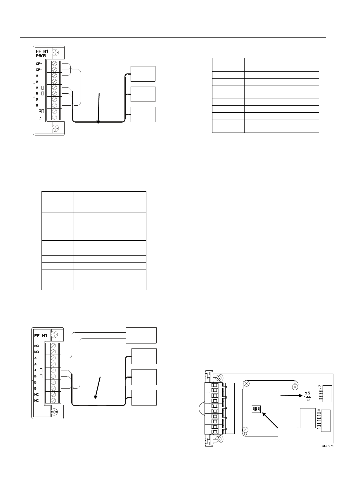
The FFI supports up to four of either of two kinds of H1
segment modules. Powered modules (see Figure 5)
provide up to 125 mA of conditioned power.
Page 6

Safe Use Instructions – FOUNDATION Fieldbus Interface
Table 2. Unpowered H1 Module Terminals
Terminal Label Definition
Fieldbus-
FF
DEVICE
compliant
wiring
DOC0780B
FF
DEVICE
FF
DEVICE
Figure 5. Field Wiring for Powered H1 Module
Table 1 identifies each terminal and its purpose on the
powered H1 module.
Table 1. Powered H1 Module Terminals
Terminal Label Definition
1 CP+ Conditioned
2 CP- Conditioned
3 A Fieldbus A
4 A Fieldbus A
5 A Fieldbus A
6 B Fieldbus B
7 B Fieldbus B
8 B Fieldbus B
9 Alarm+ Over-current
10 Alarm - Ground
Power Positive
Power Negative
open-collector
Use unpowered H1 modules and an external fieldbusapproved conditioned power supply (see Figure 6) when
you are uncertain about the power draw or the number of
fieldbus devices.
Note: The FFI supports up to four H1 modules and
Disabling the Power Conditioner on an H1 PWR
Module
If you determine that the amount of power the H1
PWR module provides is insufficient for your device,
you can disable the power conditioner on the H1
module and use external conditioned power.
Note: This option is available only for an H1 PWR
To disable the power conditioner:
1. Remove the wire channel cover.
2. Disconnect any wiring to the terminal blocks.
3. Unscrew the two captive screws holding the
module in place.
1 NC No Connection
2 NC No Connection
3 A Fieldbus A
4 A Fieldbus A
5 A Fieldbus A
6 B Fieldbus B
7 B Fieldbus B
8 B Fieldbus B
9 NC No Connection
10 NC No Connection
you can connect up to 16 fieldbus devices to
each module. However, the actual number of
devices supported depends on the power
consumption of each device and the type of
connecting cable in use.
module. You must disable the power
conditioner on the H1 PWR module before
wiring the module to external power.
Otherwise you can irreparably damage the
module’s power conditioner.
Form A6296
Page 4
+
EXTERNAL
CONDITIONED
-
POWER
Fieldbuscompliant
FF
DEVICE
wiring
FF
DEVICE
FF
DEVICE
DOC0779C
Figure 6. Field Wiring for Unpowered H1 Module
Table 2 identifies each terminal and its purpose on the
unpowered H1 module.
4. Firmly grasp the plastic lip on the edge of the
module and gently pull the module from the slot.
You may need to gently wiggle the module.
5. Position the module as shown in Figure 7.
P12 Jumper (in
ON position)
DIP switches
Figure 7. P12 Jumper on H1 PWR Module
Page 7

Safe Use Instructions – FOUNDATION Fieldbus Interface
Form A6296
Page 5
6. Move the jumper at P12 from the second and third
pins (ON) to the first and second pins (OFF).
Note: Do not adjust or change the DIP switch
settings on the H1 module. The switches are
factory-set to OFF.
7. Align the module in its slot in the FFI and slide it into
the case until the module connectors securely
contact the connectors on the backplane.
8. Tighten the captive screws on the front of the
module.
9. Wire the module.
10. Replace the wire channel cover.
Wiring the FFI CPU Module
To connect wiring to the removable block
compression terminals on the CPU module:
1. Bare the end (6.4 mm maximum) of the wire.
2. Insert the bared end into the clamp beneath the
loosened termination screw.
3. Tighten the screw.
You can wire the FFI either as an integral part of a
ROC827 or as a standalone device.
Note: Wiring the FFI to the ROC800 (“integral
wiring”) is the preferred method, since it
ensures that removing power from the
ROC800 CPU also removes power from the
FFI.
Wiring the FFI as an Integral Part of a ROC827
Insert the FFI into the ROC827 housing (as shown in
Figure 9).
Figure 8. CPU Module Wiring Terminals
Table 3 identifies each terminal and its purpose on the
CPU module.
Table 3. CPU Module Terminals
Terminal Label Definition
TB1 – 1 GND Ground
TB1 – 2 A Not Currently
TB1 – 3 B Not Currently
TB1 – 4 + Power Input
TB1 – 5 – Power Input
6 USB Not Currently
7 1 Ethernet Port
8 2 Ethernet Port
Used
Used
Positive
Negative
Used
Figure 9. FFI Inserted in ROC827
Note: The ROC827 supports a maximum of four
backplanes. If the ROC827 already contains
four backplanes, you must remove one
backplane and replace it with the FFI.
Figure 10 shows an FFI drawing power from a
ROC800. Communications to the ROC800 and
network would use the Ethernet connections on the
FFI.
Page 8

Safe Use Instructions – FOUNDATION Fieldbus Interface
Form A6296
Page 6
EXTERNAL
POWER
Figure 10. Integral Wiring of the FFI
Wiring the FFI as a Standalone Device
If you choose to configure the FFI as a standalone unit
separate from a ROC800, you must wire the FFI to its
own power supply. See Figure 11.
EXTERNAL
POWER
(unconnected to ground) system. Otherwise, follow
your company’s specific grounding practices.
However, if you are making a connection between a
grounded device and a FFI EIA-485 (RS-485) port,
ground the FFI power supply.
If you must ground the equipment, observe the
following guidelines:
• When the equipment uses a DC voltage source,
the grounding system must terminate at the
service disconnect. All equipment grounding
conductors–including wire or conduit carrying
the power supply conductors–must provide an
uninterrupted electrical path to the service
disconnect.
• Improper grounding or poor grounding practices
can often cause problems, such as introducing
ground loops into the system. Properly
grounding the FFI helps to reduce the effects of
electrical noise on the unit’s operation and
protects against lightning. Install a surge
protection device at the service disconnect on
DC voltage source systems to protect the
installed equipment against lightning and power
surges. You may also consider a telephone
surge protector for the dial-up modem
communications module.
Connect the power wiring. Determine the power
requirements as described in Chapter 3 of the
Foundation Fieldbus Interface Instruction Manual
(Form A6259).
Verifying the Connection Polarity
Figure 11. Standalone Wiring of the FFI
GROUNDING THE FFI
If your company has no specific grounding
requirements, install the FFI as a “floating”
EXTERNAL
POWER
1. To make DC power supply connections:
• If appropriate, perform the backup
configuration and log data procedure.
• Optionally, install a surge protection device at
the service disconnect.
• Remove all other power sources from the
ROC800.
• Install a fuse at the input power source.
• Remove the terminal block connector from
the socket.
• Insert the bared end of each wire into either
the clamp beneath the appropriate BAT+ /
BAT– termination screw (for the 12-volt dc
source) OR into the clamp beneath the
appropriate + / - termination screw (for the
24-volt dc source).
Note: The + terminal should also have a
fuse.
Page 9

Safe Use Instructions – FOUNDATION Fieldbus Interface
Form A6296
Page 7
• Screw each wire into the terminal block. Plug the
terminal block connector back into the socket.
• Replace all other power sources (if necessary) to
the FFI.
2. Connect the wiring to the terminal blocks on the H1
Interface modules. Refer to Chapter 4 of the
Foundation Fieldbus Interface Instruction Manual
(Form A6259) for wiring schematics and
explanations.
3. Press the wire channel covers into place over the
wiring channels, once wiring of the terminal blocks is
complete. Refer to Figure 13.
4. Apply power to start the FFI. The Power LED
indicator on the FFI (see Figure 13) should light
green to indicate that the applied voltage is correct.
5. When startup is successful, configure the FFI to meet
the requirements of the application. Refer to the Field
Interface Configurator User Manual (Form A6250).
During normal operation and use, no user
adjustments on this device are required.
6. To maintain the FFI, periodically inspect the wiring
for signs of deterioration.
Replacing the Fuse
If the server does not function but you believe it has
power and the POWER – LED does not light, you may
need to replace the 6.3 amp fuse on the CPU module
(see Figure 12).
1. Remove power from the Interface CPU module.
2. Remove the wire channel cover.
3. Disconnect all wiring from the Interface CPU
module.
4. Unscrew the two small retaining screws on the
front of the CPU module’s faceplate.
5. Grasp the lifter tabs on the edge of the CPU
module’s faceplate and gently lift the CPU
module out of its sockets on the backplane. You
should feel the module detach from the
backplane.
6. Carefully remove the CPU module from the
Interface housing. Do not scrape either side of
the CPU against the housing. Make sure not to
pull on any cables attached to the Interface.
7. Examine the fuse (refer to Figure 12) and, if
necessary, replace with a MSB 6.3A SB (Slo-Blo)
fuse.
8. Place the CPU module into its channel on the
housing.
9. Slide the CPU module down into its connectors
on the backplane.
10. Tighten the two small retaining screws on the
front of the CPU module’s faceplate.
11. Reconnect all wiring.
12. Replace the wire channel cover.
13. Restore power to the CPU module.
DISASSEMBLING THE FFI
1. Back up all configuration and log data from the
FFI. Then remove all power from the FFI and
remove any external wiring from the H1
modules.
2. Remove the FFI housing from the DIN rails by
releasing the two DIN rail catches on the top of
the back of the housing.
6.3 Amp fuse
3. Place the FFI into a box for shipping or storage.
Figure 12. CPU 6.3 Amp Fuse
Page 10

Safe Use Instructions – Foundation Fieldbus Interface
Wire
Channel
FFI CPU
Module
H1 Modules
Power
LED
Form A6296
Page 8
Figure 13. F
Bristol, Inc., Bristol Babcock Ltd, Bristol Canada, BBI SA de CV and the Flow Computer Division, are wholly owned subsidiaries of Emerson Electric Co. doing
business as Remote Automation Solutions, a division of Emerson Process Management. FloBoss, ROCLINK, Bristol, Bristol Babcock, ControlWave, TeleFlow and
Helicoid are trademarks of Remote Automation Solutions. AMS, PlantWeb and the PlantWeb logo are marks of Emerson Electric Co. The Emerson logo is a
trademark and service mark of the Emerson Electric Co. All other marks are property of their respective owners.
The contents of this publication are presented for informational purposes only. While every effort has been made to ensure informational accuracy, they are not to be
construed as warranties or guarantees, express or implied, regarding the products or services described herein or their use or applicability. Remote Automation
Solutions reserves the right to modify or improve the designs or specifications of such products at any time without notice. All sales are governed by Remote
Automation Solutions’ terms and conditions which are available upon request. Remote Automation Solutions does not assume responsibility for the selection, use or
maintenance of any product. Responsibility for proper selection, use and maintenance of any Remote Automation Solutions product remains solely with the purchaser
and end-user.
OUNDATION Fieldbus Interface
Emerson Process Management
Remote Automation Solutions
Marshalltown, IA 50158 U.S.A.
Houston, TX 77065 U.S.A.
Pickering, North Yorkshire UK Y018 7JA
© 2011 Remote Automation Solutions, division of Emerson Process Management. All Rights Reserved.
Page 11

Formblatt A6296
Hinweise zur sicheren Verwendung – FOUNDATION Fieldbus-Schnittstelle
September 2011
FOUNDATION™ Fieldbus-Schnittstelle (ROC800-Serie)
MODELL W40203
STROMVERSORGUNG: 10 BIS 30 VDC
NENNLEISTUNG: MAXIMAL 42 WATT
UMGEBUNGSTEMPERATUR: -40 BIS +75 °C
Slra 05ATEX4046X
EEx nA IIC T4, -40 °C Tamb +75 °C
MUSS IN EINEM GEHÄUSE ENTSPRECHEND IP54 ODER BESSER,
ODER AN EINEM GLEICHWERTIGEN STANDORT INSTALLIERT WERDEN.
SIEHE HINWEISE ZUR SICHEREN VERWENDUNG A6296 FÜR ZUSÄTZLICHE
BESONDERE BEDINGUNGEN ZUR SICHEREN VERWENDUNG
SOWIE SPEZIFISCHE INSTALLATIONSANWEISUNGEN
AUSTAUSCHEN DER SICHERUNG: 6,3?A TYP SLO-BLO
WARNUNG: EXPLOSIONSGEFAHR – NICHT ANSCHLIESSEN/TRENNEN
WÄHREND SPANNUNG ANLIEGT, AUSSER WENN SICHERGESTELLT IST,
DASS DER BEREICH NICHT GEFÄHRLICH IST.
Abbildung 1. FOUNDATION Fieldbus-Schnittstellenetikett
Verwenden Sie das Dokument Hinweise zur sicheren
Verwendung (SUI) zusammen mit dem F
Schnittstellen-Handbuch (Formblatt A6259). Für vollständige
Warnungen und Installationsbeschreibungen sowie
Fehlersucheprozeduren siehe Handbuch. Sollten Sie für
dieses Produkt Schulung benötigen, wenden Sie sich an Ihr
örtliches Verkaufsbüro.
Die Foundation Fieldbus-Schnittstelle (oder „FFI“) mit ATEXZulassung kann mit den H1-Segmentmodulen bestellt werden,
die in den Technischen Daten F
OUNDATION Fieldbus-Schnitt-
stelle (ROC800-Serie) (ROC800:FFI) beschrieben sind.
FFI Besondere Bedingungen zur sicheren Verwendung
Installieren Sie die Ausrüstung in einem Gehäuse
entsprechend IP54 oder besser, oder an einem
ertigen Standort. Jedes Gehäuse muss
gleichw
angemessen zertifiziert oder auf andere Art für die
Verwendungszone (Zone 2) zugelassen sein.
Der Benutzer muss sicher stellen, dass die
Eingangsnennspannung beim Gebrauch nicht
überschritten wird.
OUNDATION Fieldbus-
Stellen Sie bei einer Installation von Einheiten in
einem Gefahrenbereich sicher, dass alle
ausgewählten Installationskomponenten zur
Verwendung in solchen Bereichen gekennzeichnet
sind. Installation und Wartung dürfen nur dann
ausgeführt werden, wenn sichergestellt ist, dass
der Bereich nicht gefährlich ist. Installation oder
Wartung in einem Gefahrenbereich könnten zu
Verletzungen oder Ausrüstungsschäden führen.
Schalten Sie immer die Stromversorgung zur
Foundation Fieldbus-Schnittstelle ab, bevor Sie
mit der Verdrahtung gleich welcher Art beginnen.
Die Verdrahtung von unter Spannung stehender
Ausrüstung könnte zu Verletzungen oder
Ausrüstungsschäden führen.
Um Stromkreisschäden zu vermeiden, wenn Sie
innerhalb der Einheit arbeiten, treffen Sie
Sicherheitsmassnahmen für elektrostatische
Entladung, z. B. Tragen eines geerdeten
Handgelenkbandes.
Prüfen Sie die Polarität des Eingangsstroms, bevor
Sie die Foundation Fieldbus-Schnittstelle anschließen.
Folgende Werkzeuge sind für Installation, Wartung und
Fehlersuche erforderlich:
PC mit Microsoft® Windows® 2000 (mit Service Pack 2),
Windows XP oder Windows Vista.
ROCLINK™ 800-Konfigurationssoftware.
Kreuzschlitzschraubendreher.
Schlitzschraubendreher.
VORSICHT
VORSICHT
Konformitätserklärung
Hiermit erklärt Remote Automation Solutions, dass die
Foundation F
ieldbus-Schnittstellenprodukte mit den wesentlichen
Anforderungen und anderen relevanten Bestimmungen der
Europäischen Richtlinien 2004/108/EC (EMC) und 1994/9/EC (ATEX)
übereinstimmen.
Remote Automation Solutions
Website: www.EmersonProcess.com/Remote
D301666X412
Page 12

Hinweise zur sicheren Verwendung – FOUNDATION Fieldbus-Schnittstelle
Formblatt A6296
Seite 2
CPU-Spezifikationen
LEISTUNG (CPU)
3,56 W bei 24 VDC (Eingangsversorgung 10 bis
30 VDC).
MATERIAL
Gehäuse: Akrylnitril-Butadien-Styrol (ABS)-
Kunststoff.
Kabelkanalabdeckungen: PolypropylenKunststoff.
Module: Thermoplastisches Polyester,
lösemittelbeständig
UMGEBUNG
Betriebstemperatur: –40 bis +75 °C.
Lagerungstemperatur: –40 bis +85 °C.
Relative Feuchte: IEC68-2-3; 5–95 % nicht
kondensierend.
Vibration: IEC68-2-6; 0,15 mm oder 20 m/sec
Mechanischer Schock: IEC68-2-27;
11 Millisekunden, sinusförmige 50 Gs nicht
operativ, 15 Gs operativ
Thermischer Schock: IEC68-2-14;
Temperaturwechsel von –20 auf 85 °C
GEWICHT
Gehäuse, Rückwandplatine und CPU: 1,65 kg
H1-Modulspezifikationen
LEISTUNG (CPU)
1,18 W (vom internen Stromregler oder externer
Stromversorgung)
ÜBERSPANNUNGSSCHUTZ
± 36 VDC, Fieldbus-Anschlüsse
+ 28 VDC, Alarmanschlüsse
GEREGELTE LEISTUNGSABGABE
18 bis 24 VDC; maximal 125 mA;
Überstrom-Fehleranzeige 150 mA
ABSCHLUSSWIDERSTAND
H1-Modul mit Leistungsregelungsoption:
100 1 %, 1 uF, 50 V.
SEGMENTMODULIMPEDANZ
Übereinstimmung mit FF Standards
GEWICHT
100 g
Allgemeine Spezifikationen
ZULASSUNGEN
Bewertet nach den folgenden europäischen
Normen (EMC):
EN55011 (Störabstrahlung).
EN61000-4-2 (Störfestigkeit gegen elektrostatische
Entladung).
EN61000-4-3 (Störfestigkeit gegen
elektromagnetische Felder)
EN61000-4-4 (Störfestigkeit gegen schnelle
elektrische Einschwingvorgänge).
EN61000-4-6 (Leitungsgeführte Störfestigkeit)
Hinweis: Erfüllt Leistungskriterium B für
Störfestigkeit
Bewertet nach den folgenden europäischen
Normen (ATEX):
EN50014 (1997) +A1 +A2.
2
EN60079-15 (2003).
Zertifiziert von Sira als Modell W40203.
Produktmarkierungen für Gefahrenbereiche:
EEx nA IIC T4 – 40 °C ≤ T
II 3 G.
Zertifikat Nr. Sira 05ATEX4046X
MONTAGE DES FFI
Sie können die FFI entweder als eigenständige
Einheit oder als integrierten Bestandteil einer
ROC827 montieren. Die ROC827 unterstützt
maximal vier Rückwandplatinen. Wenn die ROC827
bereits vier Rückwandplatinen enthält, müssen Sie
eine Rückplatine entfernen und durch die FFI
ersetzen.
1. Die FFI wird in einer Box geliefert. Entnehmen
Sie sie aus der Box. Die CPU und H1-Module
werden im Werk installiert.
2. Suchen Sie eine geeignete Stelle für die FFI.
Installieren Sie die FFI immer in einem vom
Benutzer bereitgestellten Gehäuse, da die FFI
Schutz vor direkter Einwirkung durch Regen,
Schnee, Eis, verblasenem Staub oder Rückständen sowie korrosiven Atmosphären benötigt.
Wenn Sie die FFI außerhalb eines Gebäudes
installieren, platzieren Sie die FFI in einem
Gehäuse entsprechend IP54 (oder besser).
Hinweis: Dichten Sie alle Löcher ab, die Sie zu
diesem Zweck in das Gehäuse einbringen, um die Aufrechterhaltung der
Schutzart IP54 sicherzustellen.
bis ≤ +75 °C)
amb
Prüfen und kontrollieren Sie bei der Auswahl
eines Gehäuses alle Freiräume. Sorgen Sie für
angemessenen Freiraum für Verdrahtung und
Wartung. Siehe Abbildung 2 und Abbildung 3.
Page 13

Hinweise zur sicheren Verwendung – FOUNDATION Fieldbus-Schnittstelle
DIN-Schienenmontage
DIN-Schienenmontage
Formblatt A6296
Seite 3
Abbildung 2. Seitenansicht der FFI
Abbildung 3. Unteransicht der FFI
3. Das FFI-Gehäuse wird auf zwei DIN-Schienen mit
35 x 7,5 mm montiert. Siehe Abbildung 4.
Montieren Sie die oberen DIN-Schienen an der
FFI.
Abbildung 4. Rückseite der FFI
VERDRAHTUNG DER FFI-KOMPONENTEN
Die Verdrahtung der FFI umfasst das Verbinden der
Fieldbus-Geräte mit den H1-Modulen, Verdrahtung der
H1-Module mit externer Stromversorgung (wenn
geeignet), und Verdrahtung des FFI CPU-Moduls mit der
ROC oder mit externer Stromversorgung. In diesem
Dokument schlagen wir Ihnen vor, dass Sie zuerst die
Fieldbus-Geräte mit den H1-Modulen, und dann die FFI
mit der ROC (oder externer Stromversorgung) verdrahten, bevor Sie Spannung anlegen.
Die Module verfügen über entfernbare
eis:
Hinw
Klemmenleisten für einfache Verdrahtung
und Wartung. Für die I/O-Signalverdrahtung wird ein verdrilltes Kabelpaar
empfohlen. Die entfernbaren
Klemmenleisten können Drähte von
AWG 12-22 aufnehmen.
Verdrahtung der H1-Segmentmodule
Um entweder das H1 PWR oder H1-Modul (stromlos)
zu verdrahten:
Montieren Sie die unteren DIN-Schienen an der
Rückwandplatine.
Setzen Sie die FFI auf die an der
Rückwandplatine montierte untere Schiene und
achten dabei darauf, dass die Unterkante der
FFI mit der Platine bündig ist.
Drehen Sie die Oberseite der FFI so weit, bis
sie bündig an der Platine anliegt.
Ziehen Sie den oberen Streifen der DIN-
Schiene an der Platine fest.
1. Isolieren Sie das Ende des Drahtes ab (maximal
6,4 mm).
2. Führen Sie das abisolierte Ende unter der
Klemmschraube ein.
3. Ziehen Sie die Schrauben an. Siehe Abbildung
5 oder Abbildung 6.
Legen Sie ein Minimum an blankem Draht frei, um
Kurzschluss zu vermeiden, aber lassen Sie den Draht
bei der Herstellung von Verbindungen ausreichend
locker, um Zugspannung zu vermeiden.
Die FFI unterstützt bis zu vier von einer von zwei Arten
von H1-Segmentmodulen. Stromversorgungsmodule
(siehe Abbildung 5) stellen bis zu 125 mA an geregelter Leistung bereit.
Page 14
Hinweise zur sicheren Verwendung – FOUNDATION Fieldbus-Schnittstelle
)
Formblatt A6296
Seite 4
Fieldbuskonforme
Verdrahtung
ALARME
DOC0780B
Abbildung 5. Feldverdrahtung für stromversorgtes H1-Modul
Tabelle 1 identifiziert jede Klemme und ihren Zweck bei dem
stromversorgten H1-Modul.
Tabelle 1. Stromversorgte H1-Modulklemmen
Klemme Etikett Definition
1 CP+ Geregelter Strom
positiv
2 CP- Geregelter Strom
negativ
3 A Fieldbus A
4 A Fieldbus A
5 A Fieldbus A
6 B Fieldbus B
7 B Fieldbus B
8 B Fieldbus B
9 Alarm+ Überstrom
offener Kollektor
10 Alarm - Masse
Verwenden Sie stromlose H1-Module und eine für einen Fieldbus
zugelassene, externe, geregelte Stromversorgung (Siehe
Abbildung 6), wenn Sie unsicher in Bezug auf die
Leistungsaufnahme oder die Anzahl von Fieldbus-Geräten sind.
Fieldbuskonforme
Verdrahtung
FF-GERÄT
FF-GERÄT
FF-GERÄT
+
EXTERNER
GEREGELTER STROM
-
FF-GERÄT
FF-GERÄT
Tabelle 2. Stromlose H1-Modulklemmen
Klem m e Etikett Definition
1 Öffner Keine Verbindung
2 Öffner Keine Verbindung
3 A Fieldbus A
4 A Fieldbus A
5 A Fieldbus A
6 B Fieldbus B
7 B Fieldbus B
8 B Fieldbus B
9 Öffner No Connection
10 Öffner No Connection
Hinweis: Die FFI unterstützt bis zu vier H1-Module, und
Sie können an jedes Modul bis zu 16 FieldbusGeräte anschließen. Die tatsächliche Anzahl
unterstützter Geräte ist jedoch von dem
Stromverbrauch jedes Geräts, und der Art von
verwendetem Verbindungskabel abhängig.
Deaktivierung des Leistungsreglers am H1-PWR-Modul
Wenn Sie feststellen, dass der vom H1-PWR-Modul
bereitgestellte Leistungsbetrag für Ihr Gerät nicht ausreicht,
können Sie den Leistungsregler am H1-PWR-Modul
deaktivieren und extern geregelten Strom verwenden.
Hinweis: Diese Option ist nur für ein H1-PWR-Modul
verfügbar. Sie müssen den Leistungsregler am
H1-PWR-Modul deaktivieren, bevor Sie das
Modul an die externe Stromversorgung
anschließen. Andernfalls kann der Leistungsregler des Moduls irreparabel beschädigt
werden.
Deaktivierung des Leistungsreglers:
1. Entfernen Sie die Kabelkanalabdeckung.
2. Trennen Sie jede Verdrahtung von den Klemmen-
leisten.
3. Lösen Sie die zwei unverlierbaren Schrauben, die das
Modul in seiner Position halten.
4. Erfassen Sie die Kunststofflippe an der Kante des
Moduls mit festem Griff, und ziehen Sie das
Modul vorsichtig von dem Slot ab. Möglicherweise
müssen Sie das Modul vorsichtig hin- und
herbewegen.
5. Positionieren Sie das Modul entsprechend der
Darstellung in Abbildung 7.
FF-GERÄT
DOC0779C
Abbildung 6. Feldverdrahtung für stromloses H1-Modul
Tabelle 2 identifiziert jede Klemme und ihre Funktion bei
dem stromlosen H1-Modul.
P12-Jumper
(in der Stellung
„Ein“
DIP-Schalter
Abbildung 7. P12-Jumper am
H1-PWR-Modul
Page 15

Hinweise zur sicheren Verwendung – FOUNDATION Fieldbus-Schnittstelle
Formblatt A6296
Seite 5
6. Bewegen Sie den Jumper bei P12 von den zweiten
und dritten Stiften (EIN) zu den ersten und zweiten
Stiften (AUS).
Hinweis: Die Einstellungen für die DIP-Schalter am
H1-PWR-Modul nicht verstellen oder
ändern. Die Schalter sind ab Werk auf
AUS gestellt.
7. Richten Sie das Modul in seinem Slot in der FFI
aus, und schieben Sie es in das Gehäuse, bis die
Modulkonnektoren sicheren Kontakt mit den
Steckplätzen an der Rückwandplatine haben.
8. Ziehen Sie die unverlierbaren Schrauben auf der
Vorderseite des Moduls an.
9. Verdrahten Sie das Modul.
10. Setzen Sie die Kabelkanalabdeckung wieder auf.
Verdrahtung des FFI CPU-Moduls
STROM
Anschließen der Leitungen an die abnehmbare
Crimp-Klemmenleiste am CPU-Modul:
1. Isolieren Sie das Ende des Drahtes ab (maximal
6,4 mm).
2. Führen Sie das abisolierte Ende unter der
gelösten Klemmschraube ein.
3. Ziehen Sie die Schrauben an.
Sie können die FFI entweder als eigenständige
Einheit oder als integrierten Bestandteil einer
ROC827 verdrahten.
Hinweis: Die Verdrahtung der FFI mit der ROC800
(„integrierte Verdrahtung“) ist das bevorzugte
Verfahren, da hierdurch sichergestellt wird,
dass beim Unterbrechen der Stromversorgung von der ROC800 CPU auch die
Stromversorgung der FFI unterbrochen
wird.
Verdrahtung der FFI als integrierter Bestandteil
einer ROC827
Führen Sie die FFI in das ROC827-Gehäuse ein
(wie in Abbildung 9 dargestellt).
WARNUNG: TEMPERATURCODE, T4. VERWENDEN SIE DEN USB-ANSCHLUSS NICHT,
AUSSER WENN SICHERGESTELLT IST, DASS DER BEREICH NICHT GEFÄHRLICH IST.
Abbildung 8. CPU-Modul Verdrahtungsklemmen
Tabelle 3 identifiziert jede Klemme und ihre Funktion bei
dem CPU-Modul.
Tabelle 3. CPU-Modulklemmen
Klemm e Etikett Definition
TB1 – 1 ERDUNG Ma sse
TB1 – 2 A Derzeit nich t
TB1 – 3 B Derzeit nich t
TB1 – 4 + Strom versorgung
TB1 – 5 – Strom versorgung
6 USB Derzeit nicht
verwendet
verwendet
positiv
negativ
verwendet
Abbildung 9. FFI in ROC827 eingeführt
Hinweis: Die ROC827 unterstützt maximal vier
Rückwandplatinen. Wenn die ROC827
bereits vier Rückwandplatinen enthält,
müssen Sie eine Rückplatine entfernen
und durch die FFI ersetzen.
Abbildung 10 zeigt eine FFI, die Leistung von einer
ROC800 aufnimmt. Zur Kommunikation mit der
ROC800 und mit dem Netzwerk werden die
Ethernet-Anschlüsse an der FFI verwendet.
Page 16

Hinweise zur sicheren Verwendung – FOUNDATION Fieldbus-Schnittstelle
EXTERNE
STROMVERSORGUNG
„schwimmendes“ (ungeerdetes) System. Ansonsten halten
sie sich an die speziellen Erdungsverfahren Ihres Unternehmens. Wenn Sie jedoch eine Verbindung zwischen
einem geerdeten Gerät und einem FFI EIA-485 (RS-485)Port herstellen, erden Sie die FFI-Stromversorgung.
Wenn sie die Ausrüstung erden müssen, beachten Sie die
folgenden Richtlinien:
Wenn bei der Ausrüstung eine DC-Spannungsquelle
zum Einsatz kommt, muss das Erdungssystem am
Betriebsunterbrecher abgeschlossen werden. Alle
Erdungsleiter der Ausrüstung, einschließlich aller
STROM
STATUS
LIZENZSCHLÜSSEL
WARNUNG: TEMPERATURCODE, T4. VERWENDEN SIE DEN USB-ANSCHLUSS NICHT,
AUSSER WENN SICHERGESTELLT IST, DASS DER BEREICH NICHT GEFÄHRLICH IST.
Abbildung 10. Integrierte Verdrahtung der FFI
Verdrahtung der FFI als eigenständiges Gerät
Wenn Sie sich dazu entschließen, die FFI als eigenständiges
Gerät getrennt von einer ROC800 zu verdrahten, müssen Sie
die FFI mit ihrer eigenen Stromversorgung verdrahten. Siehe
Abbildung 11.
Drähte oder Leitungen, die die Stromzufuhr enthalten,
müssen mit durchgehender elektrischer Leitung am
Betriebsunterbrecher abschließen.
Unsachgemäße Erdungs- oder schlechte Erdungs-
verfahren können oftmals zu Problemen führen, wie
z. B. das Einführen von Erdungsschleifen in das
System. Eine ordnungsgemäße Erdung der FFI
fördert die Verringerung der Auswirkungen von
elektrischem Rauschen beim Betrieb der Einheit und
schützt vor Blitzschlag. Installieren Sie eine Überspannungsschutzvorrichtung am Betriebsunterbrecher
in DC-Spannungsquellensystemen, um die installierte
Ausrüstung vor Blitzschlag und Stromstößen zu
schützen. Sie können auch die Verwendung eines
Telefonüberspannungsschutzes für das Einwahlmodem-Kommunikationsmodul in Erwägung ziehen.
Schließen Sie die Netzverkabelung an. Bestimmen Sie die
Leistungsanforderungen, wie in Kapitel 3 des Foundation
Fieldbus-Schnittstellen-Handbuchs (Formblatt A6259)
beschrieben.
Überprüfung der Anschlusspolarität
Formblatt A6296
Seite 6
EXTERNE
STROMVERSORGUNG
EXTERNE
STROMVERSORGUNG
STATUS
CODES
LICENTIE-
LIZENZSCHLÜSSEL
STROM
WAARSCHUWING: TEMPERATUURCODE, T4. GEBRUIK DE USB-AANSLUITING
WARNUNG: TEMPERATURCODE, T4. VERWENDEN SIE DEN USB-ANSCHLUSS NICHT,
ALLEEN ALS BEKEND IS DAT DE LOCATIE NIET GEVAARLIJK IS.
AUSSER WENN SICHERGESTELLT IST, DASS DER BEREICH NICHT GEFÄHRLICH IST.
Abbildung 11. Eigenständige Verdrahtung der FFI
1. Herstellen der DC-Stromversorgungsverbindungen:
Wenn geeignet, führen Sie das Backup-
Konfigurations- und Datenprotokollierungsverfahren durch.
Installieren Sie optional eine Überspannungs-
schutzvorrichtung am Betriebsunterbrecher.
Entfernen Sie alle anderen Stromquellen von der
ROC800.
Installieren Sie eine Sicherung an der Eingangs-
stromquelle.
Entfernen Sie den Klemmenleistenanschluss von
der Buchse.
Führen Sie das abisolierte Ende von jedem Draht
entweder unter der passenden BAT+ / BAT–
Klemmschraube (für die 12-VDC-Quelle), ODER
in die passende Klemme unter der passenden +
/ -Klemmschraube (für die 24-VDC-Quelle) in die
Klemme ein.
Hinweis: Die + Klemme sollte ebenfalls über eine
Sicherung verfügen.
ERDUNG DER FFI
Wenn es in Ihrem Unternehmen keine speziellen Erdungsvorschriften gibt, installieren Sie die FFI als ein
Page 17

Hinweise zur sicheren Verwendung – FOUNDATION Fieldbus-Schnittstelle
1.
Schrauben Sie jeden Draht in die Klemmenleiste.
Stecken Sie den Klemmenleistenanschluss w
die Buchse ein.
Bringen Sie alle anderen Stromquellen (sofern
notw
endig) wieder an der FFI an.
ieder in
2. Schließen Sie die Verdrahtung an den Klemmenleisten an
den H1-Schnittstellenmodulen an. Siehe Kapitel 4 des
Foundation Fieldbus-Schnittstellen-Handbuchs (Formblatt
A6259) für Verdrahtungspläne und Erklärungen.
3. Drücken Sie die Kabelkanalabdeckungen in ihre Position
über den Kabelkanälen, sobald die Verdrahtung der
Klemmenleisten vollständig ist. Siehe Abbildung 13.
Unterbrechen Sie die Stromversorgung des CPUModuls der Schnittstelle.
2. Entfernen Sie die Kabelkanalabdeckung.
3. Trennen Sie die gesamte Verdrahtung von dem CPU-
Modul der Schnittstelle.
4. Lösen Sie die zwei kleinen Befestigungsschrauben an
der Vorderseite bzw. der Blende des CPU-Moduls.
5. Erfassen Sie die Hebelaschen an der Kante der Blende
des CPU-Moduls und ziehen Sie das CPU-Modul von
seinen Steckplätzen auf der Rückwand-platine ab. Sie
sollten spüren, wie sich das Modul von der Rückwandplatine löst.
Formblatt A6296
Seite 7
4. Legen Sie Spannung an der FFI an. DIE LED-
Stromanzeige an der FFI (siehe Abbildung 13) sollte grün
leuchten um anzuzeigen, dass die Spannung korrekt ist.
5. Wenn die Inbetriebsetzung erfolgreich ist, konfigurieren Sie
die FFI so, dass sie die Anforderungen der Anwendung
erfüllt. Siehe Feldschnittstellen-Konfigurations-Handbuch
(Formblatt A6250). Während normalem Betrieb und
Verwendung sind bei diesem Gerät keine Benutzereinstellungen erforderlich.
6. Um die FFI zu warten, führen Sie regelmäßig eine
Sichtprüfung der Verdrahtung auf Anzeichen von
Beschädigungen durch.
Au
stausch der Sicherung
Wenn der Server nicht funktioniert und Sie aber davon überzeugt sind,
dass er Stromversorgung hat, und die POWER-LED nicht leuchtet,
müssen Sie möglicherweise die 6,3 A-Sicherung am CPU-Modul
austauschen (siehe Abbildung 12).
6. Entfernen Sie das CPU-Modul vorsichtig aus dem
Schnittstellengehäuse. Kratzen Sie auf keiner Seite der
CPU am Gehäuse. Stellen Sie sicher, dass Sie an
keinem an der Schnittstelle befestigten Kabel ziehen.
7. Überprüfen Sie die Sicherung (siehe Abbildung 12) und
tauschen Sie sie, sofern notwendig, gegen eine
MSB 6,3 A SB (Slo-Blo)-Sicherung aus.
8. Positionieren Sie das CPU-Modul in seinem Kanal auf
dem Gehäuse.
9. Schieben Sie das CPU-Modul in seine Steckplätze auf
der Rückwandplatine nach unten.
10. Ziehen Sie die zwei kleinen Befestigungsschrauben an
der Vorderseite bzw. der Blende des CPU-Moduls an.
Schließen Sie die gesamte Verdrahtung wieder an.
11.
12. Setzen Sie die Kabelkanalabdeckung wieder auf.
13. Aktivieren Sie wieder die Stromversorgung des
CPU-Moduls.
DEMONTAG
E DER FFI
1. Führen Sie ein Backup von allen Konfigurations- und
Protokolldaten der FFI durch. Unterbrechen Sie dann
die gesamte Stromversorgung der FFI und entfernen
Sie jede externe Verdrahtung von den H1-Modulen.
2. Entfernen Sie das FFI-Gehäuse von den DIN-
Schienen, indem Sie die zwei DIN-Schienen-
6,3 ASicherung
Verriegelungselemente oben auf der Rückseite des
Gehäuses lösen.
3. Legen Sie die FFI zwecks Versand oder Lagerung in
eine Box.
Abbildung 12. CPU 6,3 A-Sicherung
Page 18

Hinweise zur sicheren Verwendung – Foundation Fieldbus-Schnittstelle
Kabelkanalabdeckungen
FFI-CPU-
Modul
H1-Module
Power
LED
Formblatt A6296
Seite 8
Abbildung 13. F
Bristol, Inc., Bristol Babcock Ltd, Bristol Canada, BBI SA de CV und Flow Computer Division sind hundertprozentige Tochtergesellschaften von Emerson Electric Co.,
die ihr Geschäft als Remote Automation Solutions („RAS“), einem Geschäftsbereich von Emerson Process Management, führt. FloBoss, ROCLINK, Bristol, Bristol
Babcock, ControlWave, TeleFlow und Helicoid sind Warenzeichen von RAS. AMS, PlantWeb und das PlantWeb-Logo sind Marken der Emerson Electric Co. Das
Emerson-Logo ist Warenzeichen und Service-Marke der Emerson Electric Co. Alle anderen Marken sind Eigentum der entsprechenden Inhaber.
Die Inhalte diese Veröffentlichung dienen ausschließlich Informationszwecken. Trotz größter Sorgfalt hinsichtlich Richtigkeit und Vollständigkeit der Informationen ist
eine Haftung oder Garantie, ausdrücklich oder stillschweigend, für die hier beschriebenen Produkte oder Dienstleistungen, deren Verwendung oder Anwendbarkeit
jedoch ausgeschlossen. RAS behält sich das Recht vor, ohne vorherige Ankündigung Entwürfe oder Spezifikationen von jeglichen Produkten zu ändern. Alle Verkäufe
unterliegen den Geschäftsbedingungen von RAS, die auf Anfrage erhältlich sind. RAS übernimmt keine Verantwortung für Auswahl, Verwendung oder Wartung von
jeglichen Produkten. Die Verantwortung für Auswahl, Verwendung oder Wartung von jeglichen RAS-Produkten liegt ausschließlich beim Käufer und Endbenutzer.
OUNDATION Fieldbus-Schnittstelle
Emerson Process Management
Remote Automation Solutions
Marshalltown, IA 50158 U.S.A.
Houston, TX 77065 U.S.A.
Pickering, North Yorkshire UK Y018 7JA
© 2011 Remote Automation Solutions, ein Geschäftsbereich von Emerson Process Management. Alle Rechte vorbehalten.
Page 19

Instructions d'utilisation et de sécurité – Interface de bus de
terrain F
OUNDATION
Modèle A6296
Septembre 2011
Interface de bus de terrain FOUNDATION™ (série ROC800)
MODÈLEW40203
PUISSANCE D'ALIMENTATION: 10 À 30VC.C.
PUISSANCE NOMINALE: 42WATTS MAXIMUM
TEMP. AMBIANTE DE FONCTIONNEMENT: -40 À +75°C
Slra 05ATEX4046X
EEx nA IIC T4, -40°C Tamb +75°C
DOIT ÊTRE INSTALLÉE DANS UN BOÎTIERIP54 OU SUPÉRIEUR, OU UN
LOGEMENT ÉQUIVALENT.CONSULTER LES AUTRES CONDITIONS
SPÉCIFIQUES RELATIVES À L'UTILISATION ET À L'INSTALLATION, DANS
LES INSTRUCTIONS D'UTILISATION ET DE SÉCURITÉA6296
REMPLACEMENT DE FUSIBLE: 6,3A À ACTION RETARDÉE
AVERTISSEMENT: RISQUE D'EXPLOSION. NE PAS BRANCHER /
DÉBRANCHER D'UN CIRCUIT SOUS TENSION SI LA ZONE N'EST PAS
LIBRE DE TOUT RISQUE.
BREVET AUX ÉTATS-UNIS 6,771,513,
6,542,832 & 6,912,483
DOC0888B
Figure 1. É
TIQUETTE DE L'INTERFACE DE BUS DE
TERRAIN FOUNDATION
Utilisez les présentes Instructions d'utilisation et de
sécurité avec le Manuel d'instructions de l'interface de
bus de terrain F
OUNDATION (modèle A6259). Consultez
ce manuel pour obtenir toutes les mesures de
précaution, explications d'installation et procédures de
dépannage. Pour toute formation concernant ce produit,
veuillez contacter votre bureau de vente local.
Si les unités sont installées dans une zone à
risque, assurez-vous que l'étiquette de
chacun des composants choisis autorise son
usage dans une telle zone. L'installation et la
maintenance doivent uniquement être
réalisées lorsque la zone est sans risque.
L'installation ou la maintenance dans une
zone à risque pourrait entraîner des
blessures ou des dégâts matériels.
Éteignez toujours l'interface de bus de terrain
Foundation avant toute intervention liée aux
fils. Toute intervention sur un équipement
branché pourrait entraîner des blessures ou
des dégâts matériels.
Pour éviter d'endommager les circuits lors
d'une intervention à l'intérieur de l'unité,
appliquez toutes les précautions pertinentes
concernant les décharges électrostatiques
(notamment, le port d'un bracelet antistatique).
Vérifiez la polarité de l'alimentation avant de
brancher l'interface de bus de terrain
Foundation.
ATTENTIONAT
ATTENTIONAT
Vous pouvez commander l'interface de bus de terrain
Foundation (ou « IBT ») homologuée ATEX avec les
modules de segment H1 décrits dans les
caractéristiques techniques de l'interface de bus de
terrain F
OUNDATION (série ROC800) (ROC800 : IBT).
Conditions spéciales d'utilisation de l'IBT
Installez l'équipement dans un boîtier IP54 ou
supérieur, ou un logement équivalent. Le boîtier
devra être certifié ou tout du moins approuvé pour
un usage dans la zone prévue (Zone 2).
L'utilisateur devra s'assurer que la tension d'entrée
nominale n'excède pas la limite autorisée en
fonctionnement.
Certificat de conformité
Remote Automation Solutions déclare par la présente
que les produits d'interface de bus de terrain
Foundation sont conformes aux principales exigences et
autres dispositions des directives européennes
2004/108/CE (EMC) et 1994/9/CE (ATEX).
Remote Automation Solutions
Site Web : www.EmersonProcess.com/Remote
Voici la liste des outils nécessaires pour
l'installation, la maintenance et le dépannage :
®
Un ordinateur exécutant Microsoft
Windows®
2000 (avec Service Pack 2), Windows XP ou
Windows Vista.
™
Logiciel de configuration ROCLINK
800.
Un tournevis Phillips.
Un tournevis à tête plate.
D301666X412
Page 20

Instructions d'utilisation et de sécurité – Interface de bus de
terrain F
OUNDATION
Modèle A6296
Page 2
Caractéristiques de l'unité centrale
ALIMENTATION (UNITÉ CENTRALE)
3,56 W à 24 Vc.c. (tension d'alimentation de 10 à
30 Vc.c.).
MATERIAUX
Boîtier : plastique acrylonitrile-butadiène-
styrène.
Caches des chemins de fil : plastique
polypropylène.
Modules : polyester thermoplastique résistant
aux solvants
CONDITIONS AMBIANTES
Temp. fonctionnement : -40 ° à +75 °C.
Temp. stockage : -40 ° à +85 °C.
Humidité relative : IEC68-2-3 ; 5–95 % sans
condensation.
Vibrations : IEC68-2-6 ; 0,15 mm ou 20 m/s
Choc mécanique : IEC68-2-27 ;
11 millisecondes, stabilité sinusoïdale de 50 G/s
hors fonctionnement, 15 G/s en fonctionnement
Choc thermique : IEC68-2-14 ; air-air de –20 °
à 85 °C
POIDS
Boîtier, fond de panier et unité centrale :
1,65 kg
Spécifications du module H1
ALIMENTATION (UNITÉ CENTRALE)
1,18 W (du conditionneur interne ou d'une source
externe)
PROTECTION CONTRE LES SURTENSIONS
± 36 Vc.c., raccords du bus de terrain
+ 28 Vc.c., raccords de l'alarme
SORTIE D'ALIMENTATION CONDITIONNÉE
18 à 24 Vc.c. ; 125 mA maximum ; signal de
panne pour surtension 150 mA
TERMINAISON
Module H1 avec option d'alimentation
conditionnée : 100 Ω 1 %, 1 uF, 50 V.
IMPÉDANCE DU MODULE DU SEGMENT
Conforme aux normes FF
POIDS
100 g
Normes habituelles
HOMOLOGATIONS
Conforme aux normes européennes (EMC)
suivantes :
EN55011 (émissions).
EN61000-4-2 (immunité aux décharges
électrostatiques).
EN61000-4-3 (immunité aux champs
électromagnétiques)
EN61000-4-4 (immunité aux transitoires électriques
rapides en salves).
EN61000-4-6 (immunité aux perturbations
conduites)
Remarque : conforme au critère de performance B
en termes d'immunité
Conforme aux normes européennes (ATEX)
suivantes :
2
EN50014 (1997) +A1 +A2.
EN60079-15 (2003).
Certifiée par Sira en tant que modèle W40203.
Indications pour zones à risque :
EEx nA IIC T4 – 40 °C ≤ T
II 3 G.
N° cert. Sira 05ATEX4046X
MONTAGE DE l'IBT
Vous pouvez monter l'IBT comme unité autonome
ou en l'intégrant à un ROC827. Un ROC827 peut
recevoir au maximum quatre fonds de panier. Si
votre ROC827 contient déjà quatre fonds de panier,
vous devez en retirer un pour installer l'IBT.
1. L'IBT vous est livrée dans un carton. Sortez-la du
carton. Le module d'unité centrale et le
module H1 sont installés en usine.
2. Trouvez l'emplacement idéal de l'IBT. Installez
toujours l'IBT dans un boîtier (non fourni), l'IBT
devant être protégée de la pluie, de la neige, du
givre, de la poussière et des atmosphères
corrosives. Si vous installez l'IBT en extérieur,
placez-la dans un boîtier IP54 (ou supérieur).
Remarque : bouchez tous les trous percés dans
le boîtier au moment de la pause
pour vous assurer de son
étanchéité.
Au moment de choisir un boîtier, tenez compte
des espaces nécessaires. Prévoyez un espace
suffisant pour les fils et le dépannage. Consultez
la figure 2 et la figure 3.
à ≤ +75 °C)
amb
Page 21

Instructions d'utilisation et de sécurité – Interface de bus de
terrain F
OUNDATION
Rail DIN
Rail DIN
Modèle A6296
Page 3
Figure 2. Vue latérale de l'IBT
Figure 3. Vue du dessous de l'IBT
3. Le boîtier de l'IBT doit être monté sur deux rails DIN
de 35 x 7,5 mm. Consultez la Figure 4.
• Montez les rails DIN supérieurs sur l'IBT.
• Montez les rails DIN inférieurs sur le fond de
panier.
Figure 4. Dos de l'IBT
CÂBLAGE DES COMPOSANTS DE L'IBT
Le câblage de l'IBT implique de brancher les
périphériques du bus de terrain aux modules H1, de
câbler les modules H1 à l'alimentation externe (le
cas échéant), et de câbler le module d'unité centrale
de l'IBT au ROC ou à l'alimentation externe. Dans le
présent document, nous recommandons de
brancher en premier lieu les périphériques du bus
de terrain aux modules H1, puis de relier l'IBT au
ROC (ou l'alimentation externe) avant de mettre
l'IBT sous tension.
Remarque : les modules disposent de blocs de
jonction amovibles pour simplifier le
câblage et le dépannage. Nous
recommandons d'utiliser un fil à paire
torsadée pour le signal E/S. Les blocs
de jonction amovibles sont compatibles
avec les fils 12-22 AWG.
Câblage des modules de segment H1
Pour câbler le module H1 PWR ou H1 (non alimenté) :
1. Dénudez l'extrémité du fil (6,4 mm maximum).
• Placez l'IBT sur les rails inférieurs montés sur le
fond de panier en vous assurant que le bord
inférieur de l'IBT s'encastre dans le panneau.
• Faites tourner le haut de l'IBT jusqu'à l'encastrer
dans le panneau.
• Fixez la bande supérieure du rail DIN au
panneau.
2. Insérez l'extrémité dénudée dans l'orifice, sous la
vis de borne.
3. Serrez la vis. Consultez la figure 5 ou la figure 6.
Évitez au maximum d'exposer la partie dénudée du fil
pour limiter le risque de court-circuit, mais laissez tout
de même un peu de jeu pour éviter toute tension du fil.
L'IBT accepte jusqu'à quatre modules de segment H1
des deux types. Les modules alimentés(figure 5)
fournissent jusqu'à 125 mA de courant conditionné.
Page 22

Instructions d'utilisation et de sécurité – Interface de bus de
terrain F
OUNDATION
Modèle A6296
Page 4
H1 PWR
IBT
Fil
PÉRIPH. IBT
compatible
bus de
PÉRIPH. IBT
ALARME
DOC0780B
PÉRIPH. IBT
Figure 5. Câblage sur site du module H1 alimenté
Le tableau 1 identifie chaque borne et décrit leur utilité
dans le module H1 alimenté.
Tableau 1. Bornes du module H1 alimenté
Terminal Étiquette Définition
1 CP+ Puissance
2 CP- Puissance
3 A Bus de terrain A
4 A Bus de terrain A
5 A Bus de terrain A
6 B Bus de terrain B
7 B Bus de terrain B
8 B Bus de terrain B
9 Alarm+ Surintensité
10 Alarm - Masse
conditionnée
positive
conditionnée
positive
co llec teur ou vert
Si vous n'êtes pas certain de l'alimentation nécessaire ou du
nombre de périphériques de bus de terrain, utilisez des
modules H1 non alimentés et une alimentation conditionnée
externe convenant aux bus de terrain (voir figure 6).
Le tableau 2 identifie chaque borne et décrit leur utilité
dans le module H1 non alimenté.
Tableau 2. Bornes du module H1 non alimenté
Terminal Étiquette Définition
1 NC Pas de connexion
2 NC Pas de connexion
3 A Bus de terrain A
4 A Bus de terrain A
5 A Bus de terrain A
6 B Bus de terrain B
7 B Bus de terrain B
8 B Bus de terrain B
9 NC Pas de connexion
10 NC Pas de connexion
Remarque : l'IBT accepte jusqu'à quatre
modules H1, sachant que vous pouvez
relier jusqu'à 16 périphériques de bus
de terrain à chaque module. En
revanche, le nombre réel de
périphériques acceptés dépend de la
consommation de chacun et du type de
câblage utilisé.
Désactivation du conditionneur d'alimentation sur
un module H1
Si vous déterminez que la puissance du module H1
PWR est insuffisante pour votre périphérique, vous
pouvez désactiver son conditionneur d'alimentation et
utiliser une alimentation conditionnée externe.
Remarque : cette option est uniquement disponible
pour un module H1 PWR. Vous devez
désactiver le conditionneur
d'alimentation du module H1 PWR
avant de relier le module à
l'alimentation externe au risque
d'endommager irrémédiablement le
conditionneur d'alimentation du
module.
+
PUISSANCE
CONDITIONNÉE
-
EXTERNE
Fil
PÉRIPH. IBT
compatible
bus de
PÉRIPH. IBT
PÉRIPH. IBT
DOC0779C
Figure 6. Câblage sur site du module H1 non alimenté
Pour désactiver le conditionneur d'alimentation :
1. Retirez le cache du chemin de fil.
2. Débranchez tout fil relié aux blocs de jonction.
3. Dévissez les deux vis imperdables maintenant
le module en place.
4. Saisissez fermement la languette en plastique
sur le rebord du module et sortez doucement le
module de son logement. Vous devrez peut-être
remuer doucement le module.
5. Placez le module comme indiqué en figure 7.
Page 23

Instructions d'utilisation et de sécurité – Interface de bus de
terrain F
OUNDATION
Tableau 3. Bornes du module d'unité centrale
Modèle A6296
Page 5
Cavalier P12
(en position ON)
Commutateurs DIP
Figure 7. Cavalier P12 sur le module H1 PWR
6. Déplacez le cavalier P12 de la seconde et troisième
broches (ON) à la première et seconde broches
(OFF).
Remarque : ne modifiez et ne réglez pas les
paramètres du commutateur DIP sur le
moduleH1. Les commutateurs sont
paramétrés sur OFF en usine.
7. Alignez le module dans son logement dans l'IBT,
puis faites-le glisser jusqu'à ce que les connecteurs
du module soient correctement en contact avec le
fond de panier.
8. Serrez les vis imperdables à l'avant du module.
9. Câblez le module.
10. Replacez le cache du chemin de fil.
Câblage du module d'unité centrale de l'IBT
Terminal Étiquette Définition
TB1 – 1 GND Masse
TB1 – 2 A Non utilisé
TB1 – 3 B Non utilisé
TB1 – 4 + Entrée d'alim.
TB1 – 5 – Entrée d'alim.
6 USB Non utilisé
7 1 Port Ethernet
8 2 Port Ethernet
positive
négative
Pour connecter les bornes du bloc de jonction
amovible au module d'unité centrale :
1. Dénudez l'extrémité du fil (6,4 mm maximum).
2. Insérez l'extrémité dénudée dans l'orifice, sous la
vis de borne dévissée.
3. Serrez la vis.
Vous pouvez câbler l'IBT comme partie intégrante
d'un ROC827 ou comme dispositif autonome.
Remarque : le câblage de l'IBT au ROC800
(« câblage intégral ») est préférable
puisque lorsque l'unité
centrale ROC800 sera mise hors
tension, l'IBT le sera également.
Câblage de l'IBT en tant que partie intégrante
d'un ROC827
Figure 8. Bornes de connexion de l'unité centrale
Le tableau 3 identifie chaque borne et décrit leur utilité
dans le module d'unité centrale.
Insérez l'IBT dans un boîtier ROC827 (comme
illustré en figure 9).
Figure 9. IBT inséré dans un ROC827
Remarque : un ROC827 peut recevoir au maximum
quatre fonds de panier. Si votre ROC827
contient déjà quatre fonds de panier, vous
devez en retirer un pour installer l'IBT.
La figure 10 reprend le schéma de l'IBT alimenté à
partir d'un ROC800. Le ROC800 et le réseau, pour
leurs communications, utiliseraient les
connexions Ethernet de l'IBT.
Page 24

Instructions d'utilisation et de sécurité – Interface de bus de
terrain F
OUNDATION
Modèle A6296
Page 6
EXTERNAL
POWER
VOFF
VOVER
TEMP.
FAULT
CPU
ETHERNET
POWER
POWERS
KEYS
LICENSE
RESET
ETHERNET
WARNING: TEMPERATURE CODE, T4. DO NOT USE USB
CONNECTOR UNLESS AREA IS KNOWN TO BE NON-HAZARDOUS.
Figure 10. Câblage intégral de l'IBT
Câblage de l'IBT en tant que dispositif autonome
Si vous choisissez d'utiliser l'IBT comme unité autonome
(indépendamment d'un ROC800), vous devez la relier à
sa propre alimentation. Consultez la figure 11.
EXTERNAL
POWER
MISE À LA TERRE DE L'IBT
Si votre société n'applique aucune procédure de mise à la
terre particulière, installez l'IBT comme système
« flottant », c'est-à-dire non relié à la terre. Autrement,
suivez la procédure de votre entreprise. Toutefois, si vous
reliez un dispositif mis à la terre au port EIA-485 (RS-485)
de l'IBT, mettez à la terre l'alimentation de l'IBT.
Si vous devez mettre l'équipement à la terre, suivez
ces consignes :
• Si l'équipement utilise une source de tension c.c.,
le circuit de mise à la terre doit pouvoir être coupé
par le disjoncteur de dépannage. Tous les
conducteurs de mise à la terre de l'équipement, y
compris le fil ou le conduit portant les conducteurs
d'alimentation, doivent fournir un chemin électrique
ininterrompu jusqu'au disjoncteur de dépannage.
• Une mauvaise mise à la terre ou une mise à la
terre maladroite entraîne généralement des
problèmes dans le circuit, notamment des boucles
de masse. Une bonne mise à la terre de l'IBT
permettra de réduire les effets du bruit électrique
en fonctionnement et préviendra tout dommage en
cas d'orage. Installez un dispositif contre les
surtensions au disjoncteur de dépannage, sur les
circuits de source de tension c.c., pour protéger
tout l'équipement contre les surtensions et en cas
d'orage. Songez également à installer une
protection contre les surtensions pour téléphones
sur le module de communication par modem.
Branchez les fils d'alimentation. Déterminez
l'alimentation nécessaire en vous aidant du chapitre
trois du Manuel d'instructions de l'interface de bus
de terrain Foundation (modèle A6259).
VOFF
VOVER
TEMP.
FAULT
CPU
ETHERNET
KEYS
LICENSE
RESET
ETHERNET
POWER
ENERGIAS
WARNING: TEMPERATURE CODE, T4. DO NOT USE USB CONNECTOR
UNLESS AREA IS KNOWN TO BE NON-HAZARDOUS.
EXTERNAL
POWER
Figure 11. Câblage de l'IBT installée en autonome
Contrôle de la polarité des branchements
1. Pour connecter une alimentation c.c. :
• Au besoin, procédez tout d'abord à une
sauvegarde de la configuration et de vos
données.
• Vous pouvez également installer, si vous le
souhaitez, un dispositif contre les surtensions
au disjoncteur de dépannage.
• Isolez le ROC800 de toutes les autres sources
d'alimentation.
• Installez un fusible à la source d'alimentation.
• Retirez le connecteur du bloc de jonction de la
prise.
• Insérez l'extrémité dénudée de chaque fil dans
l'orifice sous la vis de borne BAT+ / BAT–
correspondante (source 12 volts c.c.) OU dans
l'orifice sous la vis de borne + - correspondante
(source 24 volts c.c.).
Remarque: la borne + doit également être
équipée d'un fusible.
Page 25

Instructions d'utilisation et de sécurité – Interface de bus de
terrain F
OUNDATION
Modèle A6296
Page 7
• Vissez chaque fil au bloc de jonction.
Rebranchez le connecteur du bloc de jonction à
la prise.
• Rebranchez toutes les autres sources
d'alimentation (le cas échéant) à l'IBT.
2. Reliez les fils des blocs de jonction aux modules
d'interface H1. Consultez les schémas électriques et
descriptions du chapitre 4 du Manuel d'instructions
de l'interface de bus de terrain Foundation
(modèle A6259).
3. Une fois le câblage des blocs de jonction terminé,
remettez les caches de chemins de fil en place.
Consultez la figure 13.
4. Mettez l'IBT sous tension pour l'allumer. Le témoin
de marche de l'IBT (voir figure 13) devrait s'allumer
(vert) pour indiquer que la tension est correcte.
5. Si le démarrage réussit, configurez l'IBT
conformément aux besoins de l'application.
Reportez-vous au Manuel d'utilisation pour la
configuration d'interface de terrain (modèle A6250).
En fonctionnement standard, aucun autre réglage ne
devrait être nécessaire.
6. En ce qui concerne la maintenance de l'IBT, vérifiez
régulièrement les fils pour détecter toute
détérioration éventuelle.
1. Mettez le module d'unité centrale de l'interface
hors tension.
2. Retirez le cache du chemin de fil.
3. Débranchez tous les fils du module d'unité
centrale.
4. Dévissez les deux petites vis de retenue à l'avant
du module d'unité centrale.
5. Saisissez les languettes sur le bord de la plaque
avant du module d'unité centrale et sortez
doucement le module d'unité centrale de la prise
du fond de panier. Vous devriez sentir le module
se détacher du fond de panier.
6. Sortez doucement le module d'unité centrale du
boîtier de l'interface. Ne raclez pas les côtés de
l'unité centrale contre le boîtier. Veillez à ne tirer
sur aucun fil fixé à l'interface.
7. Examinez le fusible (voir figure 12) et, au besoin,
remplacez-le par un fusible MSB 6,3 A à action
retardée.
8. Placez le module d'unité centrale dans son
chemin, sur le boîtier.
9. Faites glisser le module d'unité centrale jusqu'à
ses connecteurs sur le fond de panier.
10. Serrez les deux petites vis de retenue à l'avant
du module d'unité centrale.
Remplacement d'un fusible
Si le serveur ne fonctionne pas, que le témoin
d'alimentation ne s'allume pas mais que vous pensez
qu'il est sous tension, tentez de remplacer le fusible de
6,3 A du module d'unité centrale (voir figure 12).
Fusible 6,3 A
11. Rebranchez tous les fils.
12. Replacez le cache du chemin de fil.
13. Remettez le module d'unité centrale sous
tension.
DÉMONTAGE DE L'IBT
1. Sauvegardez la configuration de l'IBT et toutes
vos données. Mettez l'IBT sous tension, puis
retirez tous les fils provenant des modules H1.
2. Retirez le boîtier de l'IBT de ses rails DIN en
libérant les deux fermoirs de rail en haut à
l'arrière du boîtier.
3. Placez l'IBT dans un carton pour expédition ou
stockage.
Figure 12. Fusible 6,3 A de l'unité centrale
Page 26

Instructions d'utilisation et de sécurité – Interface de bus de
terrain Foundation
Caches des
chemins de fil
Module
d'unité
centrale
de l'IBT
Modules H1
Témoin
d'alimentation
Modèle A6296
Page 8
Figure 13. I
Bristol, Inc., Bristol Babcock Ltd, Bristol Canada, BBI SA de CV et Flow Computer Division sont des filiales à 100 % de Emerson Electric Co. faisant commerce sous
le nom Remote Automation Solutions (« RAS »), une division de Emerson Process Management. FloBoss, ROCLINK, Bristol, Bristol Babcock, ControlWave, TeleFlow
et Helicoid sont des marques déposées de RAS. AMS, PlantWeb et le logo PlantWeb sont des marques commerciales de Emerson Electric Co. Le logo Emerson est
une marque déposée et une marque de service Emerson Electric Co. Toutes les autres marques sont la propriété de leurs propriétaires respectifs.
Le contenu de cette publication est uniquement destiné à des fins d'information. Bien que tout ait été mis en œuvre afin d'assurer son exactitude, il ne doit pas être
considéré comme une garantie, expresse ou implicite, concernant les produits ou services décrits dans cette publication, leur utilisation ou leur condition d'application.
RAS se réserve le droit de modifier ou d'améliorer les équipements ou les spécifications de ses produits à tout moment et sans préavis. Toutes les ventes sont gérées
selon les conditions générales de RAS, disponibles sur demande. RAS décline toute responsabilité quant au choix, à l'utilisation et à la maintenance d'un quelconque
produit. La responsabilité quant au choix, à l'utilisation et à la maintenance d'un quelconque produit de RAS reviennent entièrement à l'acheteur et à l'utilisateur final.
Emerson Process Management
Remote Automation Solutions
Marshalltown, IA 50158 États-Unis
Houston, TX 77065 États-Unis
Pickering, North Yorkshire Royaume-Uni Y018 7JA
© 2011 Remote Automation Solutions, division de Emerson Process Management. Tous trois réservés.
NTERFACE Foundation Fieldbus
Page 27

Instruções para uso seguro – FOUNDATION Fieldbus Interface
Setembro de 2011
Foundation™ Fieldbus Interface (série ROC800)
Formulário A6296
MODELO W40203
ENTRADA DE ENERGIA: 10 A 30 VCC
CLASSIFICAÇÃO DE ENERGIA: 42 WATTS MÁXIMO
TEMPERATURA AMBIENTE OPERACIONAL: -40 A +75°C
Slra 05ATEX4046X
EEx nA IIC T4, -40°C ≤ Tamb ≤ +75°C
DEVE SER INSTALADO EM IP54 OU EM MELHOR GABINETE OU LOCAL
EQUIVALENTE. CONSULTE AS INSTRUÇÕES PARA USO SEGURO A6296
PARA OBTER MAIS CONDIÇÕES ESPECIAIS DE USO SEGURO E
INSTRUÇÕES ESPECÍFICAS DE INSTALAÇÃO
SUBSTITUIÇÃO DO FUSÍVEL: 6,3 AMP, TIPO SLO-BLO
CUIDADO: RISCO DE EXPLOSÃO – NÃO CONECTE/DESCONECTE
ENQUANTO O CIRCUITO ESTIVER ATIVO, A MENOS QUE SE SAIBA QUE
A ÁREA NÃO APRESENTA PERIGO.
PATENTE NOS EUA 6,771,513,
6,542,832 E 6,912,483
DOC0888B
Figura 1. Etiqueta do F
OUNDATION Fieldbus Interface
Use este documento de instruções para uso seguro
(SUI) com o Manual de Instruções do F
OUNDATION
FIELDBUS INTERFACE (Formulário A6259). Para
informações completas sobre os cuidados a serem
tomados, descrições de instalação e procedimentos
para resolução de problemas, consulte o manual. Se
precisar de treinamento para este manual, entre em
contato com o seu escritório local de vendas.
Ao instalar unidades em áreas perigosas,
certifique-se de que todos os componentes
da instalação selecionados possuam
etiquetas que indiquem permissão de uso
nestas áreas. A instalação e a manutenção
devem ser realizadas apenas quando se
souber que a área não apresenta perigo. A
instalação ou a manutenção em áreas
perigosas pode resultar em lesões pessoais
ou danos materiais.
Sempre desligue o Foundation Fieldbus
Interface da energia antes de tentar usar
qualquer tipo de fiação. A conexão de
equipamentos energizados poderá resultar
em lesões pessoais ou danos materiais.
Para evitar danos ao circuito ao trabalhar
dentro da unidade, use as devidas
precauções contra descargas eletrostáticas,
como o uso de pulseiras antiestáticas para
aterramento.
Verifique a polaridade da energia de entrada
antes de conectar a energia ao Foundation
Fieldbus Interface.
CUIDADO
CUIDADO
O Foundation Fieldbus Interface (ou “FFI”) com
aprovação da ATEX pode ser encomendado com os
módulos do Segmento H1 descritos na especificação
técnica F
OUNDATION Fieldbus Interface (série ROC800)
(ROC800:FFI).
Condições especiais para uso seguro do FFI
Instale o equipamento em um gabinete IP54 ou
melhor, ou em local equivalente. Qualquer gabinete
deve ser adequadamente certificado ou de outra
forma aprovado para a região de utilização (Zona 2).
O usuário deverá se assegurar de que a tensão
nominal de entrada não seja ultrapassada em
serviço.
Declaração de conformidade
Por meio do presente instrumento, a Remote
Automation Solutions declara que os produtos do
Foundation Fieldbus Interface estão em conformidade
com as exigências essenciais e outras disposições
relevantes das Diretivas Europeias 2004/108/EC (EMC)
e 1994/9/EC (ATEX).
As seguintes ferramentas são necessárias para a
instalação, manutenção e resolução de problemas:
®
Computador pessoal com Microsoft
Windows®
2000 (com Service Pack 2), Windows XP ou
Windows Vista.
™
Software de configuração ROCLINK
800.
Chave de fenda Phillips.
Chave de fenda comum.
D301666X412
Remote Automation Solutions
Site: www.EmersonProcess.com/Remote
Page 28

Instruções para uso seguro – Foundation Fieldbus Interface
Formulário A6296
Página 2
Especificações da CPU
POTÊNCIA (CPU)
3,56 W a 24 V cc (fornecimento de energia 10 a
30 V cc).
MATERIAIS
Gabinete: plástico ABS (Acrilonitrilo Butadieno
Estireno).
Tampas do canal de fio: plástico de polipropileno.
Módulos: poliéster termoplástico, resistente a
solvente.
MEIO AMBIENTE
Temperatura operacional: –40 ° a +75 °C.
Temperatura de armazenamento: –40 ° a +85 °C.
Umidade relativa: IEC68-2-3; 5–95%,
sem condensação.
Vibração: IEC68-2-6; 0,15 mm ou 20 m/seg
Choque mecânico: IEC68-2-27; 11
milissegundos, 50 Gs sinusoidal, não operacional,
15 Gs operacional
Choque térmico: IEC68-2-14; de ar para ar,
de –20 ° a 85 °C
PESO
Gabinete, circuito principal e CPU: 1,65 kg
Especificações do módulo H1
POTÊNCIA (CPU)
1,18 W (do condicionador de energia interna ou
fonte de alimentação externa)
PROTEÇÃO DE SOBRETENSÃO
± 36 V cc, conexão de barramento de campo
+ 28 V cc, conexão do alarme
SAÍDA DA ENERGIA CONDICIONADA
18 a 24 V cc; 125 mA, no máximo; indicação de
falha na sobretensão 150 mA
TERMINAL
Módulo H1 com opção de energia condicionada:
100 Ω 1%, 1 uF, 50 V.
IMPEDÂNCIA DO MÓDULO DE SEGMENTO
Em conformidade com os padrões FF
PESO
100 g
Especificações comuns
APROVAÇÕES
Avaliado de acordo com os seguintes Padrões
Europeus (EMC):
EN55011 (Emissões).
EN61000-4-2 (Imunidade de Descarga
Eletrostática).
EN61000-4-3 (Imunidade de Campo
Eletromagnético).
EN61000-4-4 (Imunidade de Transientes
Rápidos Elétricos).
EN61000-4-6 (Imunidade Conduzida).
Observação: Atende ao critério B de
desempenho para imunidade
Avaliado de acordo com os seguintes
Padrões Europeus (ATEX):
2
EN50014 (1997) +A1 +A2.
EN60079-15 (2003).
Certificado pela Sira como Modelo W40203.
Marcações do produto para locais perigosos:
EEx nA IIC T4 – 40 °C ≤ T
II 3 G.
Nº. Cert. Sira 05ATEX4046X
MONTAGEM DO FFI
Você pode montar o FFI como unidade autônoma
ou como parte integral de um ROC827. O ROC827
é compatível com no máximo quatro circuitos
principais. Se o ROC827 já contiver quatro circuitos
principais, você deverá remover um circuito e
substituí-lo pelo FFI.
1. O FFI vem em uma caixa. Retire-o da caixa. Os
módulos CPU e H1 são instalados na fábrica.
2. Encontre um local adequado para o FFI. Sempre
instale o FFI em um gabinete fornecido pelo
usuário, já que o FFI necessita de proteção
contra exposição direta à chuva, neve, gelo,
sujeira vinda com o vento ou detritos, e a
atmosferas corrosivas. Se o FFI for instalado do
lado de fora, coloque-o em um gabinete
classificado como IP54 (ou melhor).
Observação: Vede qualquer orifício feito no
gabinete para esta finalidade, a
fim de garantir a manutenção da
classificação IP54 exigida.
Ao escolher um gabinete, verifique todo o espaço
ao redor. Dê espaço suficiente para a fiação e
manutenção. Consulte a Figura 2 e a Figura 3.
a ≤ +75 °C
amb
Page 29

Instruções para uso seguro – Foundation Fieldbus Interface
Montagem do trilho DIN
Montagem do trilho DIN
Formulário A6296
Página 3
Figura 2. Vista lateral do FFI
Figura 3. Vista inferior do FFI
3. O gabinete do FFI é fixado em dois trilhos DIN de
35 x 7,5 mm. Consulte a Figura 4.
• Fixe os trilhos DIN superiores no FFI.
Figura 4. Parte traseira do FFI
CONEXÃO DOS COMPONENTES DO FFI
A conexão do FFI envolve ligar os dispositivos do
barramento de campo nos módulos H1, conectando
esses módulos na energia externa (se apropriado) e
conectando o módulo CPU do FFI no ROC ou na
energia externa. Para esse documento, sugerimos
que você primeiro ligue os dispositivos de
barramento de campo nos módulos H1 e depois
ligue o FFI no ROC (ou na energia externa) antes
de aplicar energia.
Observação: Os módulos têm blocos de terminal
removíveis para garantir a conexão e
manutenção convenientes.
Recomenda-se cabo de par trançado
para conexão do sinal de E/S. Os
blocos de terminal removíveis
aceitam fio 12-22 AWG.
Conexão dos módulos do segmento H1
Para conectar o módulo H1 PWR ou H1 (não ligado):
• Fixe os trilhos DIN inferiores no circuito principal.
• Posicione o FFI no trilho inferior fixado ao
circuito principal, verificando se a borda inferior
do FFI está alinhada com o painel.
• Gire a parte superior do FFI até que fique
alinhada com o painel.
• Prenda a tira superior do trilho DIN no painel.
1. Desencape a extremidade (6,4 mm no máximo)
do fio.
2. Insira a extremidade desencapada na braçadeira,
embaixo do parafuso dos terminais.
3. Aperte o parafuso. Consulte a Figura 5 ou a
Figura 6.
Exponha o mínimo da extremidade desencapada para
impedir curtos-circuitos, mas deixe alguma folga ao
fazer as conexões para evitar deformação.
O FFI suporta até quatro de dois tipos de módulos de
segmento H1. Os módulos energizados (consulte a
Figura 5) fornecem até 125 mA de energia
condicionada.
Page 30

Instruções para uso seguro – Foundation Fieldbus Interface
Formulário A6296
Página 4
Ligação
compatível com
barramento de
campo
ALARME
DOC0780B
Figura 5. Ligação de campo para módulo H1
energizado
A Tabela 1 identifica cada terminal e seu objetivo no
módulo H1 energizado.
Tabela 1. Terminais do módulo H1 energizado
Terminal Etiqueta D efinição
1 CP+ Energia condicionada
2 CP- Energia condicionada
3 A Barramento de campo A
4 A Barramento de campo A
5 A Barramento de campo A
6 B Barramento de campo B
7 B Barramento de campo B
8 B Barramento de campo B
9 Alarme+ Sobrecorrente coletor
10 Alarme- Aterramento
positiva
negativa
aberto
Use módulos H1 não energizados e uma fonte de
alimentação condicionada aprovada para barramento de
campo externo (consulte a Figura 6) quando não tiver
certeza do uso de energia ou do número de dispositivos
do barramento de campo.
Ligação
compatível
com
barramento
de campo
DISPOSITIVO
FF
DISPOSITIVO
FF
DISPOSITIVO
FF
+
ENERGIA
CONDICIONADA
-
EXTERNA
DISPOSITIVO
FF
DISPOSITIVO
FF
DISPOSITIVO
FF
Tabela 2. Terminais do módulo H1 não energizado
Terminal Etiqueta Definição
1 NC Sem conexão
2 NC Sem conexão
3 A Barramento de campo A
4 A Barramento de campo A
5 A Barramento de campo A
6 B Barramento de campo B
7 B Barramento de campo B
8 B Barramento de campo B
9 NC Sem conexão
10 NC Sem conexão
Observação: O FFI suporta até quatro módulos H1 e
você poderá conectar até 16 dispositivos
de barramento de campo em cada
módulo. No entanto, o número real de
dispositivos suportados depende do
consumo de energia de cada dispositivo
e do tipo de cabo de conexão em uso.
Desativação do condicionador de energia em um
módulo H1 PWR
Se você determinar que a quantidade de energia
que o módulo H1 PWR fornece é insuficiente para o
seu dispositivo, é possível desativar o condicionador
de energia no módulo H1 e usar a energia
condicionada externa.
Observação: Esta opção está disponível apenas
para um módulo H1 PWR. Você
deve desativar o condicionador de
energia no módulo H1 PWR antes de
ligar o módulo na alimentação
externa. Caso contrário, poderá
danificar de forma irrecuperável o
condicionador de energia do módulo.
Para desativar o condicionador de energia:
1. Retire a tampa do canal de fios.
2. Desconecte todas as fiações dos blocos de terminal.
3. Desaparafuse os dois parafusos cativos que
prendem o módulo no lugar.
4. Segure firmemente o bordo de plástico na
extremidade do módulo e puxe o módulo com
cuidado, retirando-o da fenda. Talvez você
precise balançar levemente o módulo.
5. Posicione o módulo conforme mostrado na Figura 7.
Jumper P12
(na posição
LIGADA)
DOC0779C
Figura 6. Ligação de campo para módulo H1 não
energizado
A Tabela 2 identifica cada terminal e seu objetivo no
módulo H1 não energizado.
Microchaves DIP
Figura 7. Jumper P12 no módulo H1 PWR
Page 31

Instruções para uso seguro – Foundation Fieldbus Interface
Formulário A6296
Página 5
6. Mova o jumper no P12 do segundo e do terceiro
pinos (LIGADO) para o primeiro e o segundo pinos
(DESLIGADO).
Observação: Não ajuste nem altere as definições
da microchave DIP no módulo H1.
As microchaves vêm configuradas
de fábrica na posição DESLIGADA.
7. Alinhe o módulo na sua primeira fenda no FFI e
deslize-o para dentro do gabinete até que os
conectores do módulo entrem em contato seguro
com os conectores no circuito principal.
8. Aperte os parafusos cativos na parte dianteira do
módulo.
9. Conecte o módulo.
10. Recoloque a tampa do canal de fios.
Conexão do módulo CPU do FFI
ENERGIA
Para conectar os fios nos terminais de compressão
do bloco removível no módulo CPU:
1. Desencape a extremidade (6,4 mm no máximo)
do fio.
2. Insira a extremidade desencapada na
braçadeira, embaixo do parafuso frouxo dos
terminais.
3. Aperte o parafuso.
Você poderá conectar o FFI como parte integral de
um ROC827 ou como dispositivo autônomo.
Observação: A conexão do FFI no ROC800
("fiação integral") é o método
preferido, uma vez que garante que
a interrupção da energia do CPU
ROC800 também elimina a energia
do FFI.
Conexão do FFI como parte integral de um
ROC827
Insira o FFI no gabinete ROC827 (conforme
mostrado na Figura 9).
ENERGIAS
CUIDADO: CÓDIGO DE TEMPERATURA, T4. NÃO USE CONECTOR USB
A MENOS QUE SE SAIBA QUE A ÁREA NÃO APRESENTA PERIGO.
Figura 8. Terminais de conexão do módulo CPU
A Tabela 3 identifica cada terminal e seu objetivo no
módulo CPU.
Tabela 3. Terminais do módulo CPU
Terminal Etiqueta Definição
TB1 – 1 GND Aterramento
TB1 – 2 A Não usado
TB1 – 3 B Não usado
TB1 – 4 + Entrada de
TB1 – 5 – Entrada de
6 USB Não usado
7 1 Porta Ethernet
8 2 Porta Ethernet
atualmente
atualmente
energia positiva
energia negativa
atualmente
Figura 9. FFI inserido no ROC827
Observação: O ROC827 é compatível com no
máximo quatro circuitos principais. Se
o ROC827 já contiver quatro circuitos
principais, você deverá remover um
circuito e substituí-lo pelo FFI.
A Figura 10 mostra um FFI usando energia de um
ROC800. As comunicações com o ROC800 e a
rede usariam as conexões Ethernet no FFI.
Page 32

Instruções para uso seguro – Foundation Fieldbus Interface
Formulário A6296
Página 6
ENERGIA
EXTERNA
VDESLIGADO
VSOBRE
TEMP.
FALHA
ETHERNET
CPU
ENERGIA
ENERGIAS
LICENÇA
CHAVES DE
RESETAR
CUIDADO: CÓDIGO DE TEMPERATURA, T4. NÃO USE CONECTOR USB
A MENOS QUE SE SAIBA QUE A ÁREA NÃO APRESENTA PERIGO.
Figura 10. Fiação integral do FFI
Conexão do FFI como dispositivo autônomo
Se você preferir configurar o FFI como unidade autônoma
separada de um ROC800, deverá conectar o FFI em sua
própria fonte de alimentação. Consulte a Figura 11.
ENERGIA
EXTERNA
aterramento específicas da sua empresa. No entanto,
se estiver fazendo uma conexão entre um dispositivo
aterrado e uma porta FFI EIA-485 (RS-485), aterre a
fonte de alimentação do FFI.
Se for necessário aterrar o equipamento, observe
as seguintes diretrizes:
• Quando o equipamento usar uma fonte de
tensão DC, o sistema de aterramento deve
terminar na desconexão do serviço. Todos os
condutores de aterramento do equipamento incluindo fios ou conduítes que transportam os
condutores de fonte de energia - devem
fornecer um caminho elétrico ininterrupto até a
desconexão do serviço.
• O aterramento inadequado ou práticas
deficientes de aterramento podem, em geral,
causar problemas, como inserir loops de terra
no sistema. O aterramento adequado do FFI
ajuda a reduzir os efeitos de ruído elétrico na
operação da unidade e protege contra raios.
Instale um dispositivo de proteção contra
sobretensão na desconexão do serviço nos
sistemas de fonte de tensão DC para proteger o
equipamento instalado contra raios e oscilações
de corrente. Considere também o uso de um
protetor de sobretensão em telefones para o
módulo de comunicação com modem discado.
Conecte a fiação de energia. Determine os
requisitos de energia, conforme descrito no Capítulo
3 do Manual de Instruções do Foundation Fieldbus
Interface (Formulário A6259).
Verificação da polaridade da conexão
1. Para fazer as conexões da fonte de energia DC:
VDESLIGADO
VSOBRE
TEMP.
FALHA
ETHERNET
CPU
LICENÇA
CHAVES DE
RESETAR
CUIDADO: CÓDIGO DE TEMPERATURA, T4. NÃO USE CONECTOR USB
ENERGIA
ENERGIAS
A MENOS QUE SE SAIBA QUE A ÁREA NÃO APRESENTA PERIGO.
ENERGIA
EXTERNA
Figura 11. Conexão independente do FFI
ATERRAMENTO DO FFI
Se sua empresa não tiver exigências específicas de
aterramento, instale o FFI como sistema de “flutuação”
(desconectado do terra). Do contrário, siga as práticas de
• Se apropriado, realize o procedimento dos
dados de registro de log e de configuração
de backup.
• Como opção, instale um dispositivo de proteção
de sobretensão na desconexão do serviço.
• Remova todas as outras fontes de energia
do ROC800.
• Instale um fusível na fonte de energia de entrada.
• Remova do soquete o conector do bloco do
terminal.
• Insira a extremidade desencapada de cada
fio na braçadeira embaixo do parafuso de
terminal BAT+/BAT- (por exemplo, a fonte de
12 volts cc) OU na braçadeira embaixo do
parafuso de terminação + / - adequado (para
a fonte de 24 volts cc).
Observação: O terminal + também deve ter
um fusível.
• Aparafuse cada fio no bloco de terminal.
Insira no soquete o conector do bloco de
terminal.
• Substitua todas as outras fontes de energia
(se necessário) no FFI.
Page 33

Instruções para uso seguro – Foundation Fieldbus Interface
Formulário A6296
Página 7
2. Conecte os fios nos blocos de terminais nos
módulos do Interface H1. Consulte o Capítulo 4 do
Manual de Instruções do Foundation Fieldbus
Interface (Formulário A6259) e veja os esquemas e
as explicações sobre a fiação.
3. Pressione as tampas do canal de fios para que elas
se encaixem nos canais de fiação, quando a fiação
dos blocos de terminal estiver concluída. Consulte a
Figura 13.
4. Ligue a energia para inicializar o FFI. O indicador
LED de energia no FFI (consulte a Figura 13) deve
acender em verde para indicar que a tensão
aplicada está correta.
5. Quando a inicialização for bem-sucedida, configure o
FFI de forma a atender as exigências da aplicação.
Consulte o Manual do Usuário do Field Interface
Configurator (Formulário A6250). Durante a operação
e utilização normais, não será necessário nenhum
ajuste neste dispositivo por parte do usuário.
6. Para fazer a manutenção do FFI, inspecione
periodicamente a fiação para ver se há sinais de
deterioração.
Substituição do fusível
Se o servidor não funcionar, mas você acredita que ele
tem energia, e o LED DE ENERGIA não acender, talvez
seja necessário substituir o fusível de 6,3 Amp no
módulo CPU (consulte a Figura 12).
2. Retire a tampa do canal de fios.
3. Desconecte todos os cabos do módulo CPU do
Interface.
4. Desaparafuse os dois pequenos parafusos de
fixação na parte frontal do painel dianteiro do
módulo CPU.
5. Segure as guias de elevação na borda do painel
dianteiro do módulo CPU e levante
cuidadosamente o módulo CPU de seus soquetes
no circuito principal. Você deve sentir o módulo se
desprender do circuito principal.
6. Remova cuidadosamente o módulo CPU do
alojamento do Interface. Não arranhe nenhum
dos dois lados do CPU no alojamento. Certifiquese de não puxar os cabos conectados no
Interface.
7. Examine o fusível (consulte a Figura 12) e, se
necessário, substitua por um fusível MSB de
6,3 A (Slo-Blo).
8. Coloque o módulo CPU em seu canal no
gabinete.
9. Deslize o módulo CPU para baixo em seus
conectores no circuito principal.
10. Aperte os dois pequenos parafusos de fixação na
parte frontal do painel dianteiro do módulo CPU.
Fusível de 6,3 Amp
Figura 12. Fusível de 6,3 Amp do CPU
1. Retire a alimentação do módulo CPU do Interface.
11. Reconecte toda a fiação.
12. Recoloque a tampa do canal de fios.
13. Restaure a energia no módulo CPU.
DESMONTAGEM DO FFI
1. Faça backup de todos os dados de
configuração e de log do FFI. Depois, desligue
toda a energia do FFI e remova todos os fios
externos dos módulos H1.
2. Remova o gabinete do FFI dos trilhos DIN
liberando as duas travas do trilho DIN na parte
traseira superior do gabinete.
3. Coloque o FFI em uma caixa para transporte ou
armazenamento.
Page 34

Instruções para uso seguro – Foundation Fieldbus Interface
Tampas do
canal de
fiação
Módulo
CPU do FFI
Módulos H1
LED de
energia
Formulário A6296
Página 8
Figura 13. F
Bristol, Inc., Bristol Babcock Ltd, Bristol Canada, BBI SA de CV e a Flow Computer Division são subsidiárias pertencentes integralmente à Emerson Electric Co.,
operando como Remote Automation Solutions (“RAS”), divisão da Emerson Process Management. FloBoss, ROCLINK, Bristol, Bristol Babcock, ControlWave,
TeleFlow e Helicoid são marcas comerciais da RAS. AMS, PlantWeb e o logotipo da PlantWeb são marcas da Emerson Electric Co. O logotipo da Emerson é marca
comercial e de serviço da Emerson Electric Co. Todas as outras marcas pertencem a seus respectivos proprietários.
O conteúdo desta publicação é apresentado apenas para fins de informação. Embora se tenha dado total empenho para garantir a precisão das informações, elas
não devem ser consideradas garantias, expressas ou implícitas, em relação aos produtos ou serviços aqui descritos ou à sua utilização ou aplicabilidade. A RAS
reserva-se o direito de modificar ou aperfeiçoar os projetos ou especificações de tais produtos a qualquer momento sem aviso prévio. Todas as vendas são
controladas pelos termos e condições da RAS, que estão disponíveis mediante solicitação. A RAS não assume responsabilidade pela escolha, utilização ou
manutenção de nenhum produto. A responsabilidade pela escolha, utilização e manutenção de qualquer produto RAS continua sendo exclusivamente do comprador
e do usuário final.
OUNDATION Fieldbus Interface
Emerson Process Management
Remote Automation Solutions
Marshalltown, IA 50158 EUA
Houston, TX 77065 EUA
Pickering, North Yorkshire Reino Unido Y018 7JA
© 2011 Remote Automation Solutions, divisão da Emerson Process Management. Todos os direitos reservados.
Page 35

Инструкции по безопасной эксплуатации – интерфейс
шины F
OUNDATION Fieldbus
Форма A6296
Сентябрь 2011 г.
FOUNDATION™ Fieldbus Interface (серия ROC800)
МОДЕЛЬ W40203
ВХОДНОЕ НАПРЯЖЕНИЕ: 10-30 В DC
ПОТРЕБЛЯЕМАЯ МОЩНОСТЬ: 42 ВТ МАКС.
РАБ. ТЕМПЕР. ОКРУЖАЮЩЕЙ СРЕДЫ: ОТ -40 ДО +75 °C
Slra 05ATEX4046X
EEx nA IIC T4, -40 °C Tокр +75 °C
УСТАНОВКА ТОЛЬКО В ШКАФУ КЛАССА IP54 И ВЫШЕ ИЛИ В
ЭКВИВАЛЕНТНОМ МЕСТЕ.СМ. РУКОВОДСТВО ПО БЕЗОПАСНОЙ
ЭКСПЛУАТАЦИИ A6296 - ДОПОЛНИТЕЛЬНЫЕ СПЕЦИАЛЬНЫЕ УСЛОВИЯ
БЕЗОПАСНОЙ ЭКСПЛУАТАЦИИ И ОСОБЫЕ ИНСТРУКЦИИ ПО
УСТАНОВКЕ
ЗАМЕНА ПЛАВКИХ ПРЕДОХРАНИТЕЛЕЙ: 6,3 А, ТИП SLO-BLO
ПРЕДУПРЕЖДЕНИЕ: ВЗЫРООПАСНО – НЕ ПОДКЛЮЧАТЬ/ОТКЛЮЧАТЬ
ПОД НАПРЯЖЕНИЕМ В ЦЕПИ, ЕСЛИ НЕТ ПОДТВЕРЖДЕНИЯ О
БЕЗОПАСНОСТИ ЗОНЫ РАБОТЫ.
США - ПАТЕНТ 6,771,513,
6,542,832 & 6,912,483
W11361X0012
Рис. 1. Обозначение устройства FOUNDATION
Fieldbus Interface
Используйте
эти инструкции по безопасной
эксплуатации (SUI) вместе с руководством по
эксплуатации устройства шинного интерфейса
OUNDATION Fieldbus Interface (форма A6259). В данном
F
руководстве приведены все предупреждения и дано
описание процедур установки и устранения
неисправностей. Если требуется обучение по данной
продукции, свяжитесь с региональным офисом продаж.
Устройство Foundation Fieldbus Interface (или “FFI”) с
сертификатом ATEX можно заказать вместе с
сегментными модулями H1 Segment, описанными в
технических характеристиках Интерфейс F
OUNDATION
Fieldbus Interface, серия (ROC800) (ROC800:FFI).
Особые
условия для безопасной эксплуатации
контроллера FFI
Оборудование
должно быть установлено в шкафу
класса IP54 и выше или в эквивалентном месте.
Любой шкаф должен обладать соответствующим
сертификатом или быть иным образом одобрен для
места эксплуатации (зона 2).
Пользователь
несет ответственность за то, чтобы в
процессе эксплуатации входное напряжение не
превышало номинальных значений.
Заявление
о соответствии
Настоящим компания Remote Automation Solutions
заявляет, что изделия Foundation Fieldbus Interface
удовлетворяют необходимым требованиям и другим
соответствующим положениям Европейских директив
2004/108/EC (EMC) и 1994/9/EC (ATEX).
При ус
зонах убедитесь, что все устанавливаемые
компоненты имеют маркировку,
указывающую на возможность
эксплуатации в таких зонах. Установку и
техническое обслуживание необходимо
выполнять только в безопасных зонах.
Выполнение монтажа или технического
обслуживания в опасной зоне может
привести к получению травм или
повреждению оборудования.
Перед проведением любых монт
работ всегда отключайте устройство
Foundation Fieldbus Interface от
электропитания. Подключение
электропроводки на находящемся под
напряжением оборудовании может
привести к получению травм или
повреждению оборудования.
Во избежание повреждения цепей при
проведении работ вну
соответствующие меры против
возникновения электростатических
разрядов, например, наденьте
заземленный браслет.
Перед включением электропитания
устройства Foundation Fieldbus Interface
проверьте входную полярность.
Для
устранения неисправностей требуются следующие
средства:
Персональный компьютер с операционной системой
Microsoft
Windows XP или Windows Vista.
Конфигурационное
ROCLINK
Крестообразная
Плоская
тановке оборудования в опасных
ажных
три блока примите
установки, технического обслуживания и
®
Windows® 2000 (Service Pack 2),
™
800
программное обеспечение
отвертка;
отвертка.
D301666X412
Remote Automation Solutions
Веб-сайт: www.EmersonProcess.com/Remote
Page 36

Инструкции по безопасной эксплуатации – FOUNDATION
Fieldbus Interface
Форма A6296
Стр. 2
Технические характеристики ЦПУ
ПОТРЕБЛЯЕМАЯ МОЩНОСТЬ (ЦПУ)
3,56 Вт
10-30 В пост. тока).
МАТЕРИАЛЫ
Корпус: акрилонитрилбутадиенстирол (АБС).
Крышки
пластик.
Модули:
устойчивый к действию растворителей.
УСЛОВИЯ
Рабочая т
Температура хранения: –40° - +85°C.
Относительная влажность: IEC68-2-3; 5–95%
неконденс.
Вибрация: IEC68-2-6; 0,15 мм или 20 м/с
Устойчивость к механическим нагрузкам:
IEC68-2-27; 11 миллисекунд, синусоид. 50Gs
(нерабочая), 15 Gs (рабочая)
Устойчивость к температурным нагрузкам:
IEC68-2-14; воздух-воздух от –20° до 85°C
МАССА
Корпус, объединительная
при 24 В пост. тока (входное питание
кабель-каналов: полипропиленовый
термопластичный полиэфир,
ЭКСПЛУАТАЦИИ
емпература: –40° - +75°C.
2
плата и ЦПУ: 1,65 кг
Технические характеристики модуля
H1
ПОТРЕБЛЯЕМАЯ МОЩНОСТЬ (ЦПУ)
1,18 Вт (от
внешнего источника питания)
ЗАЩИТА
± 36 В
+ 28 В пост. тока, подключения аварийных
сигналов
ВЫХОД
18-24 В
защиты от перегрузок по току150 мА
ОКОНЕЧНОЕ
Модуль H1
питания: 100 Ω 1%, 1 мкФ, 50 В.
ИМПЕДАНС
Соответствие
МАССА
100 г
внутреннего стабилизатора или от
ОТ ИЗБЫТОЧНОГО НАПРЯЖЕНИЯ
пост. тока, эксплуатационные соединения
СТАБИЛИЗИРОВАННОГО ПИТАНИЯ
пост тока; 125 мА макс.; индикация
СОГЛАСУЮЩЕЕ УСТРОЙСТВО
с опцией стабилизированного
МОДУЛЯ SEGMENT
стандартам FF
Общие технические характеристики
СЕРТИФИКАТЫ
Сертифицирован в соот
следующими европейскими стандартами
(EMC):
EN55011 (выбросы).
EN61000-4-2 (устойчивость к электростатическим
разрядам).
EN61000-4-3 (устойчивость к наведенному
электромагнитному полю)
EN61000-4-4 (устойчивость к быстрым
электрическим переходным процессам).
EN61000-4-6 (устойчивость к кондуктивным
помехам)
Примечание: Соответствует показ
устойчивости Criterion B
Сертифицирован в соот
следующими европейскими стандартами
(ATEX):
EN50014 (1997) +A1 +A2.
EN60079-15 (2003).
сертификат Sira в качестве модели W40203.
Маркировка изделий, пр
работы в опасных зонах:
EEx нА IIC T4 – 40°C ≤ T
II 3 G.
Серт. номер Sira 05ATEX4046X
Монтаж устройства FFI
Устройство FFI
автономная единица, либо в составе устройства
ROC827. Устройство ROC827 поддерживает до
четырех объединительных плат. Если устройство
ROC827 уже оснащено четырьмя объединительными
платами, замените одну из них на устройство FFI.
устанавливается либо как
1. Контроллер FFI поставляется в коробке.
Извлеките его из коробки. На завод-изготовителе
устанавливаются модули ЦПУ и H1.
2. Найдите подходящее место установки устройства
FFI. Всегда устанавливайте устройство FFI в шкаф
(поставляется пользователем), так как это
устройство требует защиты от прямого контакта с
дождевыми каплями, снегом, льдом, находящимся
в воздухе частицам пыли и мусора и к
коррозирующим атмосферным веществам. При
установке устройства FFI вне помещений,
устройство необходимо размещать в шкафу с
классом защиты IP54 (или выше).
Примечание: Требуется
выборе шкафа учтите, что необходимо
При
обеспечить свободное пространство.
Обеспечьте достаточный зазор для монтажа и
обслуживания. См. Рис. 2 и Рис. 3.
все отверстия, выполненные в
шкафу, чтобы обеспечить его
соответствие требуемому классу
защиты IP54.
ветствии со
ателю
ветствии со
едназначенных для
до ≤ +75°C)
окр. возд.
герметично закрыть
Page 37

Инструкции по безопасной эксплуатации – FOUNDATION
Fieldbus Interface
Крепление
направляющей
DIN
Крепление
направляющей
DIN
Форма A6296
Стр. 3
Рис. 2. Вид сбоку на FFI
Рис. 3. Вид снизу на FFI
3. Корпус устройства FFI устанавливается на две
направляющих 35 x 7,5 мм DIN. См. Рис. 4.
• Установите
устройство FFI.
• Установите
объединительную плату.
• Поместите
направляющую, установленную на
объединительную плату, убедившись, что
нижняя кромка устройства FFI находится
вровень с платой.
• Поместите
позицию, так, чтобы оно находилось вровень с
платой.
• Зафиксируйте
DIN на плате.
верхние направляющие DIN на
нижние направляющие DIN на
устройство FFI на нижнюю
верхнюю часть устройства FFI на
верхнюю стяжку направляющей
Рис. 4. Задняя часть устройства FFI
ПОДКЛЮЧЕНИЕ ПРОВОДКИ КОМПОНЕНТОВ
УСТРОЙСТВА FFI
Подключение
себя подключение полевой шины к модулям H1,
подключение модулей H1 к внешнему источнику
питания (при необходимости) и подключение ЦПУ
устройства FFI на выход ROC или на внешний
источник питания. Мы рекомендуем сначала
подключить проводку устройства полевой шины к
модулям H1, а затем - FFI на выход ROC (или на
внешний источник питания) до подачи
электропитания.
Примечание: Модули
Подключение
Для подключения проводки модуля H1 PWR или H1
(не под напряжением):
1. Снимите
(макс. 6,4 мм).
2. Вставьте неизолированный конец в зажим за
клеммным винтом.
3. Затяните винт
Не рекомендуется снимать слишком большой участок
изоляции во избежание короткого
не рекомендуется натягивать провод при соединении,
так как это может привести к появлению напряжения
на растяжение.
Устройство FFI
модулей H1 обоих типов. Модули под напряжением
(см. Рис. 5) обеспечивают стабилизированное
питание до 125 мА.
проводки устройства FFI включает в
оснащены съемными
клеммными колодками для
удобства подключения и
обслуживания. Для сигнальной
проводки входов/выходов
рекомендуется применять витую
пару. К съемным клеммным
колодкам можно подключать
провода сечением до 12-22 AWG.
проводки модулей H1 Segment
изоляцию с конца провода
. См. Рис. 5 или Рис. 6.
замыкания, также
поддерживает до четырех сегментных
Page 38

Инструкции по безопасной эксплуатации – FOUNDATION
DOC0780B
УСТРОЙСТВО
FF
УСТРОЙСТВО
FF
УСТРОЙСТВО
FF
д
Fieldbus Interface
Форма A6296
Стр. 4
Fieldbus-
совместимая
электропрово
ка
ИРУЮЩЕЕ
СИГНАЛИЗ-
Рис. 5. Полевая электропроводка для модуля H1 под
напряжением
Таблица 1
определяет каждую клемму и ее назначение
модуля H1 под напряжением.
Таблица 1.
Клеммы модуля H1 под напряжением
Клемм а Маркировка Описание
1 CP+ Стабилизированное
2 CP-
3 A Полевая шина A
4 A Полевая шина A
5 A Полевая шина A
6 B Полевая шина B
7 B Полевая шина B
8 B Полевая шина B
9 Аварийный
сигнал+
10 Аварийный
сигнал-
питание (+)
Стабилизированное
питание (+)
Защита от
повышенного
напряжения
открытый коллектор
Земля
Используйте отключенные от питания модули H1 и
внешний источник стабилизированного питания,
сертифицированный для использования с внешней
полевой шиной (см. Рис. 6), если потребляемая мощность
или количество устройств полевой шины неизвестны.
+
ВНЕШНЕЕ
СТАБИЛИЗИРО-
ВАННОЕ ПИТАНИЕ
-
Fieldbus-
совместимая
электропроводка
УСТРОЙСТВО
FF
УСТРОЙСТВО
FF
УСТРОЙСТВО
FF
Таблица 2
определяет каждую клемму и ее
назначение отключенного от питания модуля H1.
Таблица 2.
Клеммы отключенного от питания
модуля H1
Клемма Маркир-
овка
1 NC Нет подключения
2 NC Нет подключения
3 A Полевая шина A
4 A Полевая шина A
5 A Полевая шина A
6 B Полевая шина B
7 B Полевая шина B
8 B Полевая шина B
9 NC Нет подключения
10 NC Нет подключения
Описание
Примечание: устройство FFI поддерживает до
четырех модулей H1, вы можете
подключить до 16 устройств полевой
шины к каждому модулю. Но
фактическое количество
поддерживаемых устройств зависит
от потребляемой мощности каждого
устройства и типа используемого
соединительного кабеля.
Выключение ст
абилизатора питания на модуле H1
PWR
Если вы решите,
что питание от модуля H1 PWR
недостаточное, вы можете отключить стабилизатор
питания модуля H1 и использовать внешний источник
стабилизированного питания.
Примечание: Эт
от вариант может использоваться
только для модуля H1 PWR.
Необходимо отключить стабилизатор
питания модуля H1 PWR до
подключения модуля к внешнему
источнику питания. В противном
случае существует опасность
повредить стабилизатор питания
модуля без возможности его
восстановления.
Для отключения стабилизатора питания:
1. Снимите
крышку кабель-канала.
2. Отсоедините всю электропроводку от клеммных
колодок.
3. Отверните два фиксирующих винта,
удерживающие
модуль.
4. Плотно возьмитесь за пластиковый язычок на
краю модуля и плавно извлеките модуль из
гнезда. При этом допускается немного
пошевелить модуль в гнезде.
5. Поместите модуль так, как показано на Рис. 7.
DOC0779C
Рис. 6. Полевая электропроводка для отключенного
от питания модуля H1
Page 39

Инструкции по безопасной эксплуатации – FOUNDATION
Д
р
Fieldbus Interface
Форма A6296
Стр. 5
Перемычка P12
(в положении
ON (Вкл.))
вухпозиционные
опереключатели
мик
Рис. 7.
Перемычка P12 на модуле H1 PWR
6. Переместите перемычку на P12 со второго и
третьего контакта (ON (Вкл.)) на первый и второй
контакт (OFF (Выкл.)).
Примечание: запрещает
ся регулировать или
изменять настройки
двухпозиционных
микропереключателей модуля H1.
Микропереключатели по умолчанию
установлены в режим OFF (Выкл.).
7. Установите
модуль в правильное положение в
гнезде на устройстве FFI и вставляйте его в корпус,
пока контакты модуля не войдут в надежное
соединение с контактами объединительной платы.
8. Затяните
фиксирующие винты на передней части
модуля.
9. Подключите
10. Установите
Подключение
электропроводку к модулю.
крышку кабель-канала.
электропроводки модуля ЦПУ
устройства FFI
Таблица 3.
Клемма Маркировка Описание
TB1 – 1 GND Земля
TB1 – 2 A Не исп ользуется
TB1 – 3 B Не исп ользуется
TB1 – 4 + Вход питания (+)
TB1 – 5 – Вход питания (-)
Клеммы модуля ЦПУ
6 USB Не исп ользуется
7 1 Порт Ethernet
8 2 Порт Ethernet
Для подключения электропроводки к съемным
зажимным клеммам на модуле ЦПУ:
1. Снимите изоляцию с конца провода
(макс. 6,4 мм).
2. Вставьте неизолированный конец в зажим за
незатянутым клеммным винтом.
3. Затяните винт.
Вы
можете подключить электропроводку к
устройству FFI, как в составе устройства ROC827,
так и в автономном варианте.
Примечание: Подключение
электропроводки
устройства FFI к устройству
ROC800 (“встроенная
электропроводка”) является
предпочтительным методом, так как
он обеспечивает отключение
питания устройства FFI при
отключении питания ЦПУ ROC800.
Подключение
электропроводки устройства
FFI в составе устройства ROC827
Вставьте
устройство FFI в корпус устройства
ROC827 (как показано на Рис.9).
ПРЕДУПРЕЖДЕНИЕ: КОД ТЕМПЕРАТУРЫ, T4. ЗАПРЕЩАЕТСЯ ИСПОЛЬЗОВАТЬ
РАЗЪЕМ USB, ЕСЛИ НЕТ ПОДТВЕРЖДЕНИЯ О БЕЗОПАСНОСТИ ЗОНЫ РАБОТЫ.
Рис. 9. Устройство FFI, вставленное в
Рис. 8. Электроразъемы модуля ЦПУ
аблице 3 приведено описание всех клемм на модули
В т
Примечание: Устройство ROC827
ЦПУ и их назначение.
устройство ROC827
поддерживает
до четырех объединительных плат.
Если устройство ROC827 уже
оснащено четырьмя
объединительными платами,
замените одну из них на устройство
FFI.
Page 40

Инструкции по безопасной эксплуатации – FOUNDATION
ВНЕШ. ИСТ.
ПИТАНИЯ
Fieldbus Interface
Форма A6296
Стр. 6
На Рис. 10 показано устройство FFI с питанием от ROC800.
Связь с устройством ROC800 и сетью, позволяет
подключаться к устройству FFI через сеть Ethernet.
ВЫКЛ
ПРЕВ
ТЕМП
ОШИБКА
СТАТУС
КЛЮЧИ
ЛИЦЕНЗИИ
СБРОС
СВЯЗЬDTR RTS COL TX RXTX RX
ПРЕДУПРЕЖДЕНИЕ: КОД ТЕМПЕРАТУРЫ, T4. ЗАПРЕЩАЕТСЯ ИСПОЛЬЗОВАТЬ
РАЗЪЕМ USB, ЕСЛИ НЕТ ПОДТВЕРЖДЕНИЯ О БЕЗОПАСНОСТИ ЗОНЫ РАБОТЫ.
Рис. 10. Встроенная электропроводка FFI
Подключение
электропроводки устройства FFI в
автономном варианте
выбрана настройка FFI в автономном варианте,
Если
отдельно от ROC800, требуется подключить устройство
FFI к собственному источнику питания. См. Рис. 11.
ВНЕШ. ИСТ.
ПИТАНИЯ
ЗАЗЕМЛЕНИЕ УСТРОЙСТВА FFI
Если
на предприятии нет особых требований по
заземлению, устройство FFI устанавливается как
незаземленная система (без подключения к земле).
В противном случае руководствуйтесь правилами,
принятым в вашей компании. Однако в случае
подключения заземленного устройства к порту EIA485 (RS-485), устройства FFI необходимо
заземлить источник питания устройства FFI.
При
необходимости заземления оборудования,
выполняйте следующие указания:
• При
использовании для питания оборудования
источника постоянного тока система
заземления должна быть подключена к точке
отключения. Все проводящие элементы
заземления оборудования, включая провода
или токоведущие элементы системы питания,
должны иметь непрерывный контакт с точкой
отключения.
• Неправильно
выполненное заземление или
неверные методы заземления могут стать
причиной таких проблем, как замыкание контура
заземления на систему. Надлежащее заземление
FFI позволяет уменьшить влияние электрических
помех на работу устройства и обеспечивает
защиту от молний. Установите защиту от
перенапряжения в точке отключения от источника
питания постоянного тока для защиты
установленного оборудования от молний и
скачков напряжения. Можно также рассмотреть
возможность использования телефонного
ограничителя бросков напряжения для модуля
модемной связи по телефонным линиям.
Подключите
электропроводку питания. Определите
требуемую потребляемую мощность, согласно
Главе 3 Руководства по устройству Foundation
Fieldbus Interface (форма A6259).
Проверка
полярности подключения
ВЫКЛ
ПРЕВ
ТЕМП
СБРОС
ОШИБКА
СТАТУ С
CODES
LICENTIE-
КЛЮЧИ
ЛИЦЕНЗИИ
СВЯЗЬ COL TX RXDTR RTS TX RX
WAARSCHUWING: TEMPERATUURCODE, T4. GEBRUIK DE USB-AANSLUITING
ALLEEN ALS BEKEND IS DAT DE LOCATIE NIET GEVAARLIJK IS.
ПРЕДУПРЕЖДЕНИЕ: КОД ТЕМПЕРАТУРЫ, T4. ЗАПРЕЩАЕТСЯ ИСПОЛЬЗОВАТЬ
РАЗЪЕМ USB, ЕСЛИ НЕТ ПОДТВЕРЖДЕНИЯ О БЕЗОПАСНОСТИ ЗОНЫ РАБОТЫ.
ВНЕШ. ИСТ.
ПИТАНИЯ
Рис. 11. Автономное подключение электропроводки
устройства FFI
1. Для подключения питания постоянного тока:
• При
необходимости выполните резервную
конфигурацию и процедуру регистрации
данных.
• Также
может потребоваться установка
устройства защиты от перенапряжения в
точке отключения.
• Отключите
все другие источники питания
устройства ROC800.
• Установите
плавкий предохранитель перед
источником питания.
• Из
влеките разъем клеммной колодки из гнезда.
• Вставьте
неизолированный конец каждого
провода в один из двух зажимов под
соответствующим клеммным винтом BAT+ /
BAT– (для источника питания 12 В
постоянного тока) ИЛИ в зажим под
соответствующим клеммным винтом "+ / -- "
(для источника питания 24 В постоянного тока).
Примечание: Клемма "+" также
должна
быть оснащена плавким
предохранителем.
Page 41

Инструкции по безопасной эксплуатации – FOUNDATION
Fieldbus Interface
Форма A6296
Стр. 7
• Зафиксируйте винтом каждый провод в
клеммной колодке. Вставьте разъем клеммной
колодки обратно в гнездо.
• Подключите
(при необходимости) к устройству FFI.
остальные источники питания
2. Подключите электропроводку к клеммным колодкам
модуля интерфейса H1. Схемы монтажа
электропроводки с пояснениями приведены в главе
4 Руководства по устройству Foundation Fieldbus
Interface (форма A6259).
3. По завершении монтажа клеммных колодок нажмите
на крышки кабель-каналов, чтобы зафиксировать их
над кабель-каналами. См. рис. 13.
4. Подайте питание для пуска устройства FFI.
Светодиодный индикатор питания устройства FFI
(см. Рис. 13) должен гореть зеленым цветом,
означающим корректное напряжение питания.
5. После успешного запуска сконфигурируйте
устройство FFI в соответствии с требованиями по
назначению. См. Руководство по настройке
устройства Foundation Fieldbus Interface (форма
A6250). При нормальной работе и стандартном
применении пользовательские регулировки данного
устройства не требуются.
6. Для поддержания нормального функционирования
устройства FFI периодически проверяйте проводку
на наличие признаков повреждений.
Замена плавких п
Если
сервер не функционирует, но, предположительно,
на него подается питание, а индикатор питания POWER
не горит, может потребоваться замена плавкого
предохранителя 6,3 А модуля ЦПУ (см. Рис. 12).
редохранителей
1. Отключите питание модуля ЦПУ.
2. Снимите крышку кабель-канала.
3. Отсоедините всю проводку интерфейсного
модуля ЦПУ.
4. Отвинтите два фиксирующих винта в передней
части лицевой панели модуля ЦПУ.
5. Возьмитесь за подъемные петли на кромке
лицевой панели модуля ЦПУ и плавно извлеките
модуль ЦПУ из гнезда на объединительной
плате. Вы должны почувствовать момент, когда
модуль отделяется от объединительной платы.
6. Аккуратно извлеките модуль ЦПУ из корпуса
интерфейсного устройства. Не поцарапайте
поверхность ЦПУ о корпус. Запрещается тянуть
за провода интерфейсного устройства.
7. Осмотрите плавкий предохранитель (см Рис. 12)
и, при необходимости, замените его плавким
предохранителем MSB 6,3A SB (Slo-Blo).
8. Установите модуль ЦПУ в его паз на корпусе.
9. Вставьте модуль ЦПУ так, чтобы он вошел в
соприкосновение с его контактами на
объединительной плате.
10. Затяните два фиксирующих винта в передней
части лицевой панели модуля ЦПУ.
11. Установите всю проводку.
12. Установите крышку кабель-канала.
13. Подайте питание на модуль ЦПУ.
РАЗБОРКА FFI
Плавкий
предохранитель
6,3 А
Рис. 12. Плавкий предохранитель ЦПУ 6,3 А
Создайте резервную копию всех данных
1.
конфигурации и журнала FFI. Затем отключите
питание от устройства FFI и отсоедините
внешнюю электропроводку от модулей H1.
2. Снимите корпус FFI с направляющих DIN,
открыв два зажима направляющих DIN в верней
части задней панели корпуса.
3. Поместите устройство FFI в тару для
транспортировки или хранения.
Page 42

Инструкции по безопасной эксплуатации – серия ROC809
Стр. 8
Крышки
каналов
проводки
Модуль ЦПУ
устройства FFI
Модули H1
Индикатор
питания
Форма A6155
Рис. 13. FOUNDATION Fieldbus Interface
Корпорация Bristol, Inc., компании Bristol Babcock Ltd, Bristol Canada, BBI SA de CV и Flow
Emerson Electric, и осуществляющими свою деятельность от имени Remote Automation Solutions (“RAS”), подразделения Emerson Process Management.
FloBoss, ROCLINK, Bristol, Bristol Babcock, ControlWave, TeleFlow и Helicoid являются товарными знаками компании RAS. AMS, PlantWeb и логотип PlantWeb
являются товарными знаками компании Emerson Electric. Логотип Emerson является товарным знаком и знаком обслуживания компании Emerson Electric.
Все остальные товарные знаки являются собственностью соответствующих владельцев.
Данный доку
может использоваться в качестве гарантий или гарантийных обязательств, явных или подразумеваемых, в отношении описанных здесь изделий и услуг, их
использования и применимости. Компания RAS оставляет за собой право в любое время изменять или улучшать конструкцию и характеристики своих
изделий без предварительного уведомления. Весь объем продаж регулируется условиями и положениями компании RAS, которые предоставляются по
требованию. Компания RAS не принимает на себя ответственность за выбор изделия, его использование или обслуживание. Ответственность за
правильность выбора продукции компании RAS, ее использование и обслуживание возлагается исключительно на покупателя и конечного пользователя.
мент публикуется исключительно в ознакомительных
целях. Информация, содержащаяся в этом документе, какой бы точной она ни была, не
Computer Division являются собственными дочерними компаниями
Emerson Process Management
Flow Computer Division
Marshalltown, IA 50158 U.S.A.
Houston, TX 77065 U.S.A.
Pickering, North Yorkshire UK Y018 7JA
© 2011 Remote Automation Solutions, подразделение Emerson Process Management. Все права защищены.
Page 43
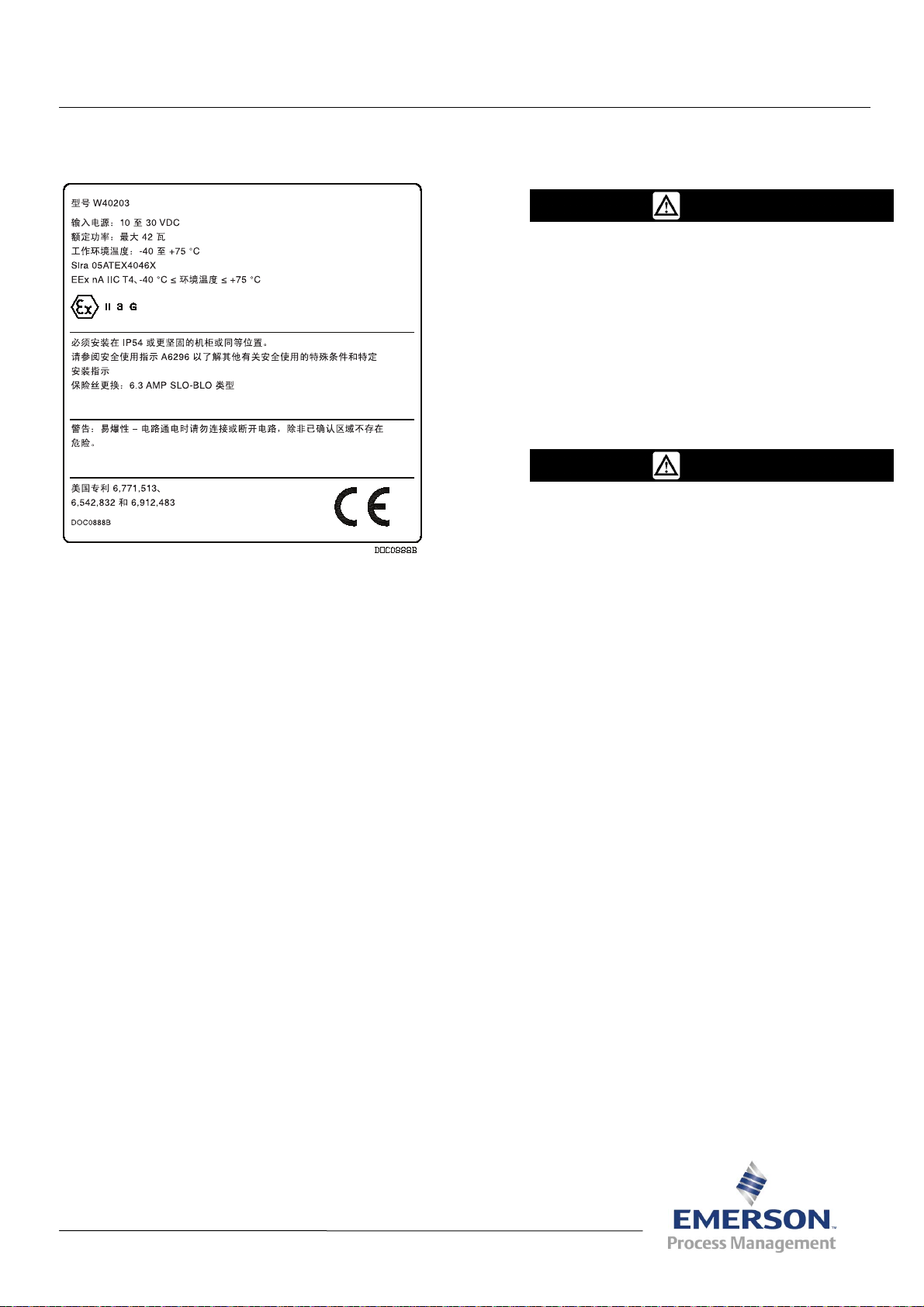
安全使用说明 – FOUNDATION 现场总线接口
年9月
警告
警告
FOUNDATION™ 现场总线接口(ROC800 系列)
表 A6296
2011
图
1. FOUNDATION
使用此安全使用说明(SUI)文档和 F
线接口安装手册(表
程的所有注意事项和说明,请参阅此手册。如果您需要
有关此产品的培训,请联系当地销售处。
订购通过 ATEX 审批的 Foundation 现场总线接口(简称
为“FFI”)时,可以选购 F
(
ROC800
H1 分段模块。
系列)
A6259)。有关安装和故障排除过
(ROC800:FFI)技术规格中说明的
现场总线接口标签
OUNDATION
OUNDATION
现场总线接口
现场总
在危险区域安装组件时,请确保所选的所有安装
组件都标明了可以用于这些区域。必须在确认地
点安全后,才可以执行安装和维护。在危险区域
安装或维护可能导致人员受伤或财产损坏。
进行任何接线操作前都必须切断 Foundation 现
场总线接口的电源。对通电设备进行接线可能会
造成人员受伤或财产损坏。
为防止在单元内工作时损坏电路,请采取适当的
静电放电防护措施(例如佩戴接地腕带)。
将 Foundation 现场总线接口连接至电源前请检
查输入电源的极性。
安装、维护和故障排除需要使用以下工具:
®
运行 Microsoft
Pack 2)、Windows XP 或 Windows Vista 的
个人计算机。
ROCLINK
十字槽螺丝刀。
平头螺丝刀。
Windows® 2000(含 Service
™
800 组态软件。
FFI 安全使用特殊条件
将设备安装在 IP54 或更坚固的机柜或同等位置。
任何机柜都应通过相关认证,或通过使用区域
(区域 2)的审批。
用户应确保使用时不会超过额定输入电压。
符合性声明
Remote Automation Solutions 特此声明 Foundation 现
场总线接口产品符合欧洲指令 2004/108/EC (EMC) 和
1994/9/EC (ATEX) 中适用的基本要求和其他相关规定。
Remote Automation Solutions
网站:www.EmersonProcess.com/Remote
D301666X412
Page 44
安全使用说明 – FOUNDATION 现场总线接口
表 A6296
页码 2
CPU 规格
电源 (CPU)
24 V dc 时为 3.56 W(输入电压为 10 至
30 V dc)。
材料
盒:丙烯腈-丁二烯-苯乙烯 (ABS) 塑料。
线槽盖板:聚丙烯塑料。
模块:热塑性聚酯,耐溶剂。
环境
工作温度:–40° 至 +75°C。
存储温度:–40° 至 +85°C。
相对湿度:IEC68-2-3;5–95%(非冷凝)。
振动:IEC68-2-6;0.15 mm 或 20 m/sec
机械震动:IEC68-2-27;11 毫秒,正弦 50G
(非运行)、15 G(运行)
热冲击:IEC68-2-14;空对空从 –20° 至 85°C
重量
外壳、背板和 CPU:1.65 kg
2
H1 模块规格
电源 (CPU)
1.18 W(从内部功率调节器或外部电源)
过电压保护
± 36 V dc,现场总线连接
+ 28 V dc,警报连接
调节电源输出
18 至 24 V dc;最大 125 mA;150 mA 出现过
流故障指示
通用规格
审批
已通过以下欧洲标准的评估 (EMC):
EN55011(放射性)。
EN61000-4-2(抗放静电)。
EN61000-4-3(电磁场抗扰性)。
EN61000-4-4(电气快速瞬变抗扰)。
EN61000-4-6(传导抗扰性)
注:符合抗扰性性能标准 B
已通过以下欧洲标准的评估 (ATEX):
EN50014 (1997) +A1 +A2。
EN60079-15 (2003)。
已通过 Sira 的 Model W40203 认证。
危险场所使用产品标记:
EEx nA IIC T4 – 40°C ≤ 环境温度 ≤ +75°C
II 3 G。
证书编号 Sira 05ATEX4046X
安装 FFI
您可以把 FFI 当做独立的装置或 ROC827 的组成部
分来安装。ROC827 最多可支持 4 个背板。如果
ROC827 已经装有 4 个背板,则必须拆除其中一个
背板,并用 FFI 来替换它的位置。
1. 交付时,FFI 使用箱子包装。将它从箱中取出。出
厂时已安装 CPU 和 H1 模块。
2. 寻找 FFI 的合适安装位置。FFI 应始终安装在用
户提供的机柜中,因为 FFI 不可直接暴露于雨、
雪、冰、浮尘或碎屑以及腐蚀性空气中。如果要在
室外安装 FFI,则将其置于 IP54 (或更好)级别
要求的机柜之中。
端子
H1 模块含调节电源选项:100 Ω 1%、1 uF、
50 V。
分段模块阻抗
符合 FF 标准
重量
100 g
注: 密封机柜上的所有孔洞,以确保达到所需
的 IP54 级维护。
选择机柜时,一定要检查所有空隙。为接线和维修
保留足够的空隙。请参阅
图
2 和图 3。
Page 45

安全使用说明 – FOUNDATION 现场总线接口
DIN 导轨安装
DIN 导轨安装
表 A6296
页码 3
图
2. FFI
图
3. FFI
3. FFI 外壳安装到两个 35 x 7.5 毫米的 DIN 导轨。
请参阅
图
4。
侧视图
底视图
图
4. FFI
FFI 组件接线
FFI 接线包括:将现场总线设备接至 H1 模块;将 H1
模块接至外部电源(如果适合);将 FFI CPU 模块
接至 ROC 或外部电源。对于此文档,我们建议您先
将现场总线设备接至 H1 模块,然后在通电前将 FFI
接至 ROC(或外部电源)。
注: 为便于接线和维修,模块的接线端子是可移除
的。推荐使用双绞线进行 I/O 信号接线。可移
除的接线端子能接受 12-22 AWG 的接线。
H1 分段模块接线
要进行 H1 PWR 或 H1(非供电)模块接线,请执行
以下操作:
1. 剥开线缆的末端(最多 6.4 毫米)。
2. 将裸露端插入螺钉端子下方的接线夹中。
背面
• 将上 DIN 导轨安装到 FFI。
• 将下 DIN 导轨安装在背板上。
• 将 FFI 放在安装到背板的下导轨上,确保
FFI 的下缘与面板平接。
• 转动 FFI 顶部直至其与面板平接。
• 将 DIN 导轨的上腕带固定到面板上。
3. 拧紧螺钉。请参阅
尽量减少裸线外露部分以防止短路,但在连接时使电
线略为松弛以避免绷得过紧。
FFI 最多支持四个这两种 H1 分段模块之一。供电模块
(请参阅
图
5)最高提供 125 mA 的调节电源。
图
5 或图 6。
Page 46

安全使用说明 – FOUNDATION 现场总线接口
表 A6296
页码 4
表
2. H1
非供电模块端子
现场总线合规接线
图
5. 对 H1
表
1 列出了 H1 供电模块上的每个端子及其用途。
端子 标签 定义
1 CP+
2 CP-
3 A
4 A
5 A
6 B
7 B
8 B
9
10
供电模块进行现场接线
表
1. H1
供电模块端子
调节电源正极
调节电源负极
现场总线 A
现场总线 A
现场总线 A
现场总线 B
现场总线 B
现场总线 B
警报 + 过电流集电极开路
警报 - 接地
当您不确定现场总线设备的功耗或编号时,请使用非供
电的 H1 模块和一个通过现场总线审批的外部调节电源
(请参阅
图 6)。
端子 标签 定义
1 NC
2 NC
3 A
4 A
5 A
6 B
7 B
8 B
9 NC
10 NC
无连接
无连接
现场总线 A
现场总线 A
现场总线 A
现场总线 B
现场总线 B
现场总线 B
无连接
无连接
注: FFI 最多支持四个 H1 模块,并且您最多可
以将 16 个现场总线设备连接至每个模块。
但是,支持设备的实际编号取决于每个设备
的功耗及所用连接缆线的类型。
禁用 H1 PWR 模块上的功率调节器
如果您确定 H1 PWR 模块所提供的电量不够设备所
需,则可禁用 H1 模块上的功率调节器并使用外部调
节电源。
注: 该选项仅适用于 H1 PWR 模块。将模块接至
外部电源之前,必须先禁用 H1 PWR 模块上
的功率调节器。否则,将对模块的功率调节
器造成不可恢复的损坏。
要禁用功率调节器,请:
1. 拆除线槽盖板。
2. 断开所有接至接线端子的线缆。
3. 旋松固定模块的两颗系紧螺钉。
4. 抓紧模块边缘的塑料凸缘,轻轻地从插槽拉动模
块。您可能需要轻轻地扭动模块。
现场总线合规接线
图
6. 对 H1
表
2 列出了 H1 非供电模块上的每个端子及其用途。
非供电模块进行现场接线
5. 将模块放在
图
7 所示的位置。
P12 跳线
(置于 ON 位置)
DIP 开关
图
7. H1 PWR
模块上的
P12
跳线
Page 47

安全使用说明 – FOUNDATION 现场总线接口
表 A6296
页码 5
6. 将 P12 跳线从第二和第三个引脚 (ON) 移到第一和第
二个引脚 (OFF)。
注: 请勿调节或更改 H1 模块上的 DIP 开关设置。
这些开关在出厂时设定为 OFF。
7. 使模块对准 FFI 插槽并将其滑入盒中,直到模块连接
器稳固接触背板上的连接器。
8. 拧紧模块正面的系紧螺钉。
9. 连接模块。
10. 更换线槽盖板。
对 FFI CPU 模块接线
要将接线连接至 CPU 模块上可移除的压紧式端子块,
请执行以下操作:
1. 剥开线缆的末端(最多 6.4 毫米)。
2. 将裸露端插入松开的螺钉端子下方的接线夹中。
3. 拧紧螺钉。
您可以把 FFI 当做 ROC827 的组成部分或独立的装
置来进行接线。
注: 将 FFI 接至 ROC800(“整体布线”)是首
选方法,因为它能确保从 ROC800 CPU 去掉
电源时也能从 FFI 去掉电源。
将
FFI
当做
ROC827
将 FFI 插入 ROC827 外壳(如
的组成部分来进行接线
图
9 所示)。
图
8. CPU
表
3 列出了 CPU 模块上的每个端子及其用途。
表
端子 标签 定义
TB1 – 1 GND
TB1 – 2 A
TB1 – 3 B
TB1 – 4 +
TB1 – 5 –
6 USB
7 1
8 2
模块接线端子
3. CPU
模块端子
接地
当前未使用
当前未使用
电源输入正极
电源输入负极
当前未使用
以太网接口
以太网接口
图
9.
插入
ROC827 的 FFI
注: ROC827 最多可支持 4 个背板。如果 ROC827
已经装有 4 个背板,则必须拆除其中一个背
板,并用 FFI 来替换它的位置。
图
10 显示了 FFI 从 ROC800 获取电源的方式。可使用
FFI 上的以太网连接与 ROC800 以及网络进行通信。
Page 48

安全使用说明 – FOUNDATION 现场总线接口
表 A6296
页码 6
的特定接地惯例。但是,如果您正在连接接地设备和
FFI EIA-485 (RS-485) 端口,请将 FFI 电源接地。
如果您必须使设备接地,请遵循以下指引:
• 如果设备使用的是直流电源,接地系统必须与电
气接入点断开(即保持“悬空”状态)。所有的
设备接地体(包括导线和电源供电线路)在电气
接入点之前必须有一条不间断的电流通路。
• 错误接地或接地不良经常会引起问题,例如将接
地回路引入系统。FFI 正确接地可帮助减少电噪
声对设备运行的影响,并免遭雷电袭击。在直流
电压电源系统的服务中断处安装浪涌保护设备,
以保护安装的设备不受雷电和电涌的影响。对于
拨号调制解调器通信模块,您还可以考虑使用电
话浪涌保护器。
图
10. FFI
将
FFI
当做独立的设备进行接线
若选择把 FFI 当做独立于 ROC800 的装置进行配置,则
必须将 FFI 接至其自有的电源。请参阅
的完整接线
图
11。
连接电源接线。确定 Foundation
手册
(表 A6259)
验证连接的极性
1. 要连接 DC 电源,请执行以下操作:
• 如果适合,请执行组态和日志数据的备份
程序。
• 还可以在服务停止处安装浪涌保护设备。
• 断开 ROC800 的所有电源。
• 在输入电源处安装保险丝。
• 拔下插孔上的接线端子接头。
• 将每根线缆的裸露端插入相应 BAT+ / BAT–
螺钉端子下方的接线夹中(针对 12 V dc 电
源)或相应 + / – 螺钉端子下方的接线夹中
(针对 24 V dc 电源)。
注: 正端子也必须配备保险丝。
• 将每条线缆旋紧到接线端子。将接线端子接头
插回插孔。
第三章
中说明的电源要求。
现场总线接口安装
图
11. FFI
将 FFI 接地
如果您的公司没有特定的接地要求,则请将 FFI 作为
“浮动”(不接地)系统来安装。否则,请按照贵公司
的独立接线
• 更换 FFI 的其他所有电源(如果必要)。
2. 将接线连接到 H1 接口模块上的接线端子。请参阅
Foundation
的
第四章
3. 完成接线端子的接线后,将线槽盖板在线槽按入到
位。请参阅
4. 接通电源启动 FFI。FFI 上的电源 LED 指示灯
(请参阅
电压正确。
现场总线接口安装手册
了解接线图示和说明。
图
13。
图
13)应呈绿色亮起,指示所应用的
(表 A6259)
Page 49

安全使用说明 – FOUNDATION 现场总线接口
表 A6296
页码 7
5. 成功启动后,请配置 FFI 以满足应用要求。请参阅
场接口组态软件用户手册(表
A6250)。设备的正常
现
运行和使用过程中,不需要用户进行调整。
6. 要维护 FFI,请定期检查接线是否有损坏迹象。
更换保险丝
如果服务器不工作且 POWER – LED 不亮但您又确信已
通电时,可能需要更换 CPU 模块上的 6.3 A 保险丝(请
参阅
图
12)。
6.3 A 保险丝
1. 从接口 CPU 模块去掉电源。
2. 拆除线槽盖板。
3. 从接口 CPU 模块断开所有接线。
4. 旋松 CPU 模块面板正面的两颗小固定螺钉。
5. 抓住 CPU 模块面板边缘的移片器翼片,小心地将
CPU 模块从背板上的插孔内提出。您应该感觉到
模块脱离背板。
6. 小心地从接口外壳拆除 CPU 模块。不要让 CPU
的任一侧刮到外壳。确保不要拉动接至接口的任何
一根线缆。
7. 检查保险丝(请参阅
图
12)并在必要时用 MSB
6.3A SB (Slo-Blo) 保险丝更换。
8. 将 CPU 模块放置到外壳上的槽内。
9. 将 CPU 模块向下滑进背板上的连接器内。
10. 拧紧 CPU 模块面板正面的两颗小固定螺钉。
11. 重新连接所有接线。
12. 更换线槽盖板。
13. 对 CPU 模块恢复供电。
拆卸 FFI
1. 备份 FFI 的所有组态和日志数据。然后,切断 FFI
的所有电源,并移除 H1 模块的所有外部接线。
2. 松开外壳背面顶部的两个 DIN 导轨锁环,将 FFI
图
12. CPU 6.3 A
保险丝
外壳从 DIN 导轨中移除。
3. 将 FFI 放入箱中,以便存放或运输。
Page 50

安全使用说明 – Foundation 现场总线接口
FFI CPU
模块
电源 LED
表 A6296
页码 8
线槽盖板
H1 模块
图
13. FOUNDATION
Bristol, Inc.、Bristol Babcock Ltd、Bristol Canada、BBI SA de CV 和 Flow Computer Division 是艾默生电气公司的全资子公司。它们经营的业务与 Emerson Process
Management 的 Remote Automation Solutions (“RAS”) 部相同。FloBoss、ROCLINK、Bristol、Bristol Babcock、ControlWave、TeleFlow 和 Helicoid 是 RAS 的商
标。AMS、PlantWeb 和 PlantWeb 徽标是艾默生电气公司的标识。Emerson 徽标是艾默生电气公司的商标和服务标识。所有其它标识均为其各自所有人的财产。
本出版物的内容仅供参考。我们已尽最大努力确保信息的准确性,这些信息不得视为对此处所述产品或服务以及其使用或适用性的明示或暗示保证或担保。RAS 有权随
时修改或改进产品的设计或规格,而不另行通知。所有销售均受 RAS 的条款和条件的制约,这些条款或条件在要求时可提供。RAS 对任何产品的选择、使用和维护概
不负责。购买者和最终用户应该独自承担正确选择、使用和维护任何 RAS 产品的责任。
现场总线接口
Emerson Process Management
Remote Automation Solutions
Marshalltown, IA 50158 U.S.A.
Houston, TX 77065 U.S.A.
Pickering, North Yorkshire UK Y018 7JA
© 2011 Emerson Process Management,Remote Automation Solutions 部。保留所有权利。
Page 51

زاﺮﻃA6296
ﺮﺒﻤﺘﺒﺳ 2011
ﺖﻴﺒﺜﺘﻟا ﺮﺻﺎﻨﻋ ﻞآ ّن أ ﻦﻣ ﺪآﺄﺗ ،ةﺮﻄﺧ ﺔﻘﻄﻨﻣ ﻲﻓ تاﺪﺣﻮﻟا ﺖﻴﺒﺜﺗ ﺪﻨﻋ
تﺎﻤﻴﻠﻌﺘﻟا ﺔﻌﺟاﺮﻤﺑ ﻚﻟذو ،ﻖﻃﺎﻨﻤﻟا ﻩﺬه ﻲﻓ ماﺪﺨﺘﺳﻼﻟ ﺔﻠﺑﺎﻗ ةدﺪﺤﻤﻟا
ﺎﻬﻴﻠﻋ ةدراﻮﻟا . ﺔﻘﻄﻨﻤﻟا نﻮﻜﺗ ﻦﻴﺣ ﻂﻘﻓ ﺔﻧﺎﻴﺼﻟاو ﺖﻴﺒﺜﺘﻟﺎﺑ مﺎﻴﻘﻟا ﺐﺠﻳ
ةﺮﻄﺧ ﺮﻴﻏ .ﺜﺘﻟا يدﺆﻳ نأ ﻦﻜﻤﻳ ﻰﻟإ ةﺮﻄﺧ ﺔﻘﻄﻨﻣ ﻲﻓ ﺔﻧﺎﻴﺼﻟا وأ ﺖﻴﺒ
تﺎﻜﻠﺘﻤﻤﻟا ﻲﻓ رﺮﺿ وأ ﺔﻴﺼﺨﺷ ﺔﺑﺎﺻإ.
FOUNDATION
ﻵا ماﺪﺨﺘﺳﻻا تﺎﻤﻴﻠﻌﺗ ﻦﻣ– F OUNDATION Fieldbus Interface
™
Fieldbus Interface )ﺔﺌﻓ-ROC800(
ﻤﺋاد
تﻼﻴﺻﻮﺘﻟا ﻦﻣ عﻮﻧ يﺄﺑ مﻮﻘﺗ نأ . تاﺪﻌﻤﻟا ﻞﺻو يدﺆﻳ نأ ﻦﻜﻤﻳ
تﺎﻜﻠﺘﻤﻤﻟا ﻲﻓ رﺮﺿ وأ ﺔﻴﺼﺨﺷ ﺔﺑﺎﺻإ ﻰﻟإ ﺔﻠﻐﺸﻤﻟا.
ﺿ يأ ﻰﻟإ ﺔﻴﺋﺎﺑﺮﻬﻜﻟا ةراﺪﻟا ضﺮﻌﺗ يدﺎﻔﺘﻟﻞﻤﻌﻟا لﻼﺧ رﺮ
ﻢﺼﻌﻣ طﺎﺑر ﻊﺿﻮآ ﻲﺋﺎﺑﺮﻬﻜﻟا ﻎﻳﺮﻔﺘﻟا تﺎﻃﺎﻴﺘﺣا ﺪﻤﺘﻋا ،ةﺪﺣﻮﻟا ﻲﻓ
زﺎﻬﺟ ﺪﻳوﺰﺗ ﻞﺒﻗ ﺔﻳﺬﻐﺘﻟا ﺔﻗﺎﻃ ﺔﻴﺒﻄﻗ ﻦﻣ ﻖﻘﺤﺗFoundation
Fieldbus Interface ﺔﻗﺎﻄﻟﺎﺑ .
ﻞآﺎﺸﻤﻟا فﺎﺸﺘآاو ﺔﻧﺎﻴﺼﻟاو ﺖﻴﺒﺜﺘﻠﻟ ﺔﻳروﺮﺿ ﺔﻴﻟﺎﺘﻟا تاودﻷا ّن إ
®
Windows
®
ﻐﺸﺗ مﺎﻈﻨﺑ ﻲﺼﺨﺷ ﺮﺗﻮﻴﺒﻤآﻞﻴMicrosoft
Windows Vista .
™
800 ROCLINK .
ﺲﺒﻠﻴﻓ ﺐّﻠﺼﻣ ﻚﻔﻣ .
سأﺮﻟا ﺢﻄﺴﻣ ﻲﻏاﺮﺑ ﻚﻔﻣ .
ﻞﻴﻐﺸﺗ ﻒﻗوأFoundation Fieldbus Interface ﻞﺒﻗ ﺎً
ضرﺆﻣ.
ﺎﻬﺘﺠﻟﺎﻌﻣو :
2000 ) ﻊﻣService Pack 2 ( وأWindows XP وأ
داﺪﻋإ ﺞﻣﺎﻧﺮﺑ
اﻟﻢﺳﺮ
1 .
ﺔﻣﻼﻋ
FOUNDATION Fieldbus Interface
ﻦﻣﻵا ماﺪﺨﺘﺳﻻا تﺎﻤﻴﻠﻌﺗ ﺪﻨﺘﺴﻣ مﺪﺨﺘﺳا)SUI ( تﺎﻤﻴﻠﻌﺗ ﻞﻴﻟد ﻊﻣ
F
OUNDATION Fieldbus Interface ) زاﺮﻃA6259 .( ﻰﻠﻋ عﻼﻃﻼﻟ
OUNDATION Fieldbus Interface
تﺎﺣوﺮﺸﻟاو تﺎﻬﻴﺒﻨﺘﻟا ﻞآ ﻞآﺎﺸﻤﻟا فﺎﺸﺘآاو ﺖﻴﺒﺜﺘﻟا تاءاﺮﺟﺈﺑ ﺔﺻﺎﺨﻟا
تﺎﻤﻴﻠﻌﺘﻟا ﻞﻴﻟد ﻊﺟار ،ﺎﻬﺘﺠﻟﺎﻌﻣو . ،ﺞﺘﻨﻤﻟا اﺬه ﻰﻠﻋ ﺐﻳرﺪﺘﻟا ﻰﻟإ ﺖﺠﺘﺣا اذإ
ﻚﻳﺪﻟ ﻲﻠﺤﻤﻟا تﺎﻌﻴﺒﻤﻟا ﺐﺘﻜﻤﺑ ﻞﺼﺗﺎﻓ.
زﺎﻬﺟ ﺐﻠﻃ ﻦﻜﻤﻳFoundation Fieldbus Interface ) وأ"FFI ("
ﻞﺒﻗ ﻦﻣ ﻪﻴﻠﻋ قّﺪﺼﻤﻟاATEX ﻢﺴﻘﻟا تاﺪﺣو ﻊﻣH1 ﺎﻬﺣﺮﺷ ﻢﺗ ﻲﺘﻟا ﻲﻓ
ﺔﻴﻨﻔﻟا تﺎﻔﺻاﻮﻤﻟاF
) ﺔﺌﻓROC800( )ROC800:FFI .(
طوﺮﺷFFI ﻦﻣﻵا ماﺪﺨﺘﺳﻼﻟ ﺔﺻﺎﺨﻟا
ﻲﻓ زﺎﻬﺠﻟا ﺖّﺒﺛIP54 ﻞﺛﺎﻤﻣ ﻊﻗﻮﻣ ﻲﻓ وأ ﻞﻀﻓأ ﺔﻳوﺎﺣ ﻲﻓ وأ . نأ ﻲﻐﺒﻨﻳ
ﺔﻘﻄﻨﻤﻟ ﺔﺒﺳﺎﻨﻤﻟا ﺔﻘﻓاﻮﻤﻟا وأ ﻖﻳﺪﺼﺘﻟا ﻰﻠﻋ ﺔﻣﺪﺨﺘﺴﻤﻟا ﺔﻳوﺎﺤﻟا ﻰﻈﺤﺗ
ماﺪﺨﺘﺳﻻا)ﻘﻄﻨﻤﻟا ﺔ2 .(
ﺔﻳﺬﻐﺘﻟا ﺪﻬﺟ لﺪﻌﻣ ﻦﻣ ﻰﺼﻗﻷا ﺪﺤﻟا ﻲﻄﺨﺗ مﺪﻋ مﺪﺨﺘﺴﻤﻟا ﻦﻤﻀﻳ نأ ﺐﺠﻳ
ﺔﻣﺪﺨﻟا لﻼﺧ .
ﺔﻘﺑﺎﻄﻤﻟا نﻼﻋإ
ﻦﻠﻌﺗRemote Automation Solutions تﺎﺠﺘﻨﻣ ّن أ ﻪﺒﺟﻮﻤﺑ
و ﺔﻴﺳﺎﺳﻷا تﺎﺒﻠﻄﺘﻤﻠﻟ ﺔﻘﺑﺎﻄﻣ
D301666X412
Foundation Fieldbus Interface مﺎﻜﺣأ
ﺔﻠﺼﻟا تاذ ىﺮﺧﻷا ﺔﻴﺑوروﻷا تﺎﻬﻴﺟﻮﺘﻟا
2004/108/EC (EMC) و .1994/9/EC (ATEX)
Remote Automation Solutions
ﻲﻧوﺮﺘﻜﻟﻹا ﻊﻗﻮﻤﻟا :www.EmersonProcess.com/Remote
Page 52

زاﺮﻃA6296
ﺔﺤﻔﺻ2
ﻦﻣﻵا ماﺪﺨﺘﺳﻻا تﺎﻤﻴﻠﻌﺗ– F oundation Fieldbus Interface
ﻰﻟإ≤75 + ﺔﺟرد
ﻂﻴﺤﻤﻟا
ﺔآﺮﺘﺸﻤﻟا تﺎﻔﺻاﻮﻤﻟا
تﺎﻘﻳﺪﺼﺘﻟا
ﺔﻴﻟﺎﺘﻟا ﺔﻴﺑوروﻷا ﺮﻴﻳﺎﻌﻤﻟا ﺐﺴﺤﺑ ﻢﻴﻴﻘﺘﻟا ﻢﺗ )EMC(:
)تاراﺪﺻإ(.EN55011
EN6100-4-2 )ﻲﺋﺎﺑﺮﻬﻜﻟا ﻎﻳﺮﻔﺘﻟا ﺔﻋﺎﻨﻣ.(
EN61000-4-3 )ﻲﺴﻴﻃﺎﻨﻐﻣوﺮﻬﻜﻟا ناﺪﻴﻤﻟا ﺔﻋﺎﻨﻣ(
EN61000-4-4 )ﻊﻳﺮﺴﻟا ﻲﺋﺎﺑﺮﻬﻜﻟا رﻮﺒﻌﻟا ﺔﻋﺎﻨﻣ.(
EN61000-4-6 )ﺔﻟﻮﻘﻨﻤﻟا ﺔﻋﺎﻨﻤﻟا (
ﺔﻈﺣﻼﻣ: ءادﻷا رﺎﻴﻌﻣ ﻊﻣ ﻖﻓاﻮﺘﺗB ﺔﻋﺎﻨﻤﻠﻟ
ﺔﻴﻟﺎﺘﻟا ﺔﻴﺑوروﻷا ﺮﻴﻳﺎﻌﻤﻟا ﺐﺴﺤﺑ ﻢﻴﻴﻘﺘﻟا ﻢﺗ )ATEX(:
A2.
EN50014 )1997+ (A1+
EN60079-15(2003) .
ﻦﻣ ﺔﻗّﺪﺼﻣSira ﻞﻳدﻮﻤآW40203.
ةﺮﻄﺨﻟا ﻊﻗاﻮﻤﻠﻟ ﺞﺘﻨﻤﻟا تاﺪﻳﺪﺤﺗ:
EEx nA IIC T4 - 40 ﺔﻳﻮﺌﻣ ﺔﺟرد≤ ةراﺮﺣ
ﺔﻳﻮﺌﻣ (
II 3 G .
ةدﺎﻬﺸﻟا ﻢﻗرSira 05ATEX4046X
ﺔﻳﺰآﺮﻤﻟا ﺔﺠﻟﺎﻌﻤﻟا ةﺪﺣو تﺎﻔﺻاﻮﻣ
ﺔﻗﺎﻃ)ﺔﻳﺰآﺮﻤﻟا ﺔﺠﻟﺎﻌﻤﻟا ةﺪﺣو (
3.56 ةﻮﻘﺑ طاو24 رﺎﻴﺗ ﺎًﺘﻟﻮﻓ ﺮﻤﺘﺴﻣ) ﻦﻣ ﺔﻳﺬﻐﺘﻟا ﺔﻗﺎﻃ10 ﻰﻟإ30
ﺮﻤﺘﺴﻣ رﺎﻴﺗ ﺎًﺘﻟﻮﻓ.(
داﻮﻤﻟا
ﺔﺒﻠﻋ: ﻦﻳﺮﻴﺘﺳإ ﻦﻴﻳادﺎﺗﻮﻴﺑ ﻞﻳﺮﺘﻴﻧﻮﻠﻳﺮآأ ﻚﻴﺘﺳﻼﺑ)ABS.(
كﻼﺳﻷا ةﺎﻨﻗ ﺔﻴﻄﻏأ: ﻦﻴﻠﻴﺑوﺮﺑ ﻲﻟﻮﺑ ﻚﻴﺘﺳﻼﺑ.
تاﺪﺣﻮﻟا: ﺔﻣوﺎﻘﻣ تﺎﺒﻳﺬﻣو يراﺮﺣ ﻲﻜﻴﺘﺳﻼﺑ تاﺮﺘﺳا ﻲﻟﻮﺑ
ﺔﺌﻴﺒﻟا تﺎﻔﺻاﻮﻤﻟا
ﻞﻴﻐﺸﺘﻟا ةراﺮﺣ: –40 ﻰﻟإ +75ﺔﻳﻮﺌﻣ ﺔﺟرد
ﻦﻳﺰﺨﺘﻟا ةراﺮﺣ: –40 ﻰﻟإ +85ﺔﻳﻮﺌﻣ ﺔﺟرد
2
ﻣ20 ﺮﺘﻣ/ﺔﻴﻧﺎﺜﻟا
ﺔﻴﺒﺴﻨﻟا ﺔﺑﻮﻃﺮﻟا: IEC68-2-3 ؛5–95 %ﻒﺛﺎﻜﺘﻣ ﺮﻴﻏ.
زاﺰﺘهﻻا: IEC68-2-6 ؛0.15 وأ ﻢﻠ
ﺔﻴﻜﻴﻧﺎﻜﻴﻣ ﺔﻣﺪﺻ: IEC68-2-27 ؛11 ﻲﺒﻴﺟ ﻞﻜﺸﺑ ،ﺔﻴﻧﺎﺛ ﻲﻠﻠﻣ50
ﺔﻴﺿرأ ﺔﻴﺑذﺎﺟ عرﺎﺴﺗ ةﺪﺣو)G ( ،ﻞﻴﻐﺸﺘﻟا فﺎﻘﻳإ ﻊﺿو ﻲﻓ15 ةﺪﺣو
ﺔﻴﺿرأ ﺔﻴﺑذﺎﺟ عرﺎﺴﺗ)G (ﻞﻴﻐﺸﺘﻟا ﻊﺿو ﻲﻓ
ﺔﻳراﺮﺣ ﺔﻣﺪﺻ: IEC68-2-14 ﻦﻣ ﻲﺋاﻮه لدﺎﺒﺗ ؛ –20 ﻰﻟإ 85
ﺔﻳﻮﺌﻣ ﺔﺟرد
نزﻮﻟا
ﺖﻴﺒﺜﺗ FFI
ﺔﺠﻟﺎﻌﻤﻟا ةﺪﺣوو ةزﺰﻌﻤﻟا ﺔﻴﻧوﺮﺘﻜﻟﻹا ﺔﺣﻮﻠﻟاو ﻲﺟرﺎﺨﻟا فﻼﻐﻟا
ﺔﻳﺰآﺮﻤﻟا: 1.65 ﻎﻠآ
زﺎﻬﺟ ﺖﻴﺒﺜﺗ ﻚﻨﻜﻤﻳFFI ﺎﻣإ ﻦﻣ أﺰﺠﺘﻳ ﻻ ءﺰﺠآ وأ ﺔﻠﻘﺘﺴﻣ ةﺪﺣﻮآ
ROC827 . ﻢﻋﺪﻳROC827 ﻊﺑرأ ﺪﺤآ ةزﺰﻌﻣ ﺔﻴﻧوﺮﺘﻜﻟإ تﺎﺣﻮﻟ
ﻰﺼﻗأ . نﺎآ لﺎﺣ ﻲﻓوROC827 ﺔﻴﻧوﺮﺘﻜﻟإ تﺎﺣﻮﻟ ﻊﺑرأ ﻰﻠﻋ يﻮﺘﺤﻳ
ةﺪﺣو تﺎﻔﺻاﻮﻣ H1
زﺎﻬﺠـﺑ ﺎﻬﻟاﺪﺒﺘﺳاو ةﺪﺣاو ﺔﺣﻮﻟ ﺔﻟازإ ﻚﻴﻠﻋ ،ةزﺰﻌﻣFFI .
ﺔﻗﺎﻃ)ﺔﻳﺰآﺮﻤﻟا ﺔﺠﻟﺎﻌﻤﻟا ةﺪﺣو (
1. زﺎﻬﺟ ﻢﻴﻠﺴﺗ ﻢﺘﻳFFI ﺔﺒﻠﻋ ﻲﻓ .ﺔﺒﻠﻌﻟا ﻦﻣ ﻪﺟﺮﺧأ .ﺠﻟﺎﻌﻤﻟا ةﺪﺣو نﻮﻜﺗ ﺔ
ﺳﺎﺳأ ﺔﺘّﺒﺜﻣ .
تاﺪﺣوو ﺔﻳﺰآﺮﻤﻟاH1 ﻊﻨﺼﻤﻟا ﻲﻓ ﺎً
1.18 طاو)ﺔﻴﺟرﺎﺨﻟا ﺔﻗﺎﻄﻟا ﺮّﻓﻮﻣ ﻰﻟإ ﺔﻴﻠﺧاﺪﻟا ﺔﻗﺎﻄﻟا ﻦّﺴﺤﻣ ﻦﻣ (
ﺪﺋاﺰﻟا ﺪﻬﺠﻟا ﻦﻣ ﺔﻳﺎﻤﺤﻟا
2. زﺎﻬﺟ ﻊﺿﻮﻟ ﺐﺳﺎﻨﻣ ﻊﻗﻮﻣ ﻦﻋ ﺚﺤﺑاFFI . زﺎﻬﺟ ﺖﻴﺒﺜﺗ ﻰﻟإ ﺎًﻣود ﺪﻤﻋا
FFI ّن ﻷ ،مﺪﺨﺘﺴﻤﻟا ﺎﻬﻨّﻣﺆﻳ ﻲﺘﻟا ﺔﻳوﺎﺤﻟا ﻲﻓFFI ﺔﻳﺎﻤﺣ ﺐّﻠﻄﺘﻳ
± 36 تﻼﺻو ،ﺮﻤﺘﺴﻣ رﺎﻴﺗ ﺎًﺘﻟﻮﻓ fieldbus
+ 28 ﻪّﺒﻨﻤﻟا تﻼﺻو ،ﺮﻤﺘﺴﻣ رﺎﻴﺗ ﺎًﺘﻟﻮﻓ
ﻞآﺂﺘﻟاو مﺎﻄﺤﻟا وأ رﺎﺒﻐﻟاو ﺪﻴﻠﺠﻟاو ﺞﻠﺜﻟاو ﺮﻄﻤﻟا ﻦﻣ ةﺮﺷﺎﺒﻣ . ﺖﻤﻗ اذإ
ﺖﻴﺒﺜﺘﺑFFI ،ﻰﻨﺒﻤﻟا جرﺎﺧ ﺔﻳوﺎﺣ ﻲﻓ ﻪﻌﻀﻓIP54 )ﻞﻀﻓأ ﺔﻳوﺎﺣ وأ (
ﺔﺒﺳﺎﻨﻤﻟا.
ﺔﻨّﺴﺤﻤﻟا جاﺮﺧﻹا ﺔﻗﺎﻃ
ﻦﻣ18 ﻰﻟإ24 ؛ﺮﻤﺘﺴﻣ رﺎﻴﺗ ﺎًﺘﻟﻮﻓ125 ؛ﻰﺼﻗأ ﺪﺤآ اًﺮﻴﺒﻣأ ﻲﻠﻠﻣ
150 إ اًﺮﻴﺒﻣأ ﻲﻠﻠﻣﺪﺋاز رﺎﻴﺗ ﻰﻟإ ﺄﻄﺧ ةرﺎﺷ
ﺳ ﻰﻠﻋ صﺮﺣا
ﺔﻴﻧﺎﻜﻣإ ﺔﻧﺎﻴﺻ نﺎﻤﻀﻟIP54 ﺔﺑﻮﻠﻄﻤﻟا .
تﺎﺤﺴﻔﻟا ﻞآ ﻦﻣ ﻖﻘﺤﺗ ،ﺔﻳوﺎﺤﻟا رﺎﻴﺘﺧا ﺪﻨﻋ . ﺔﺒﺳﺎﻨﻣ تﺎﺤﺴﻓ ﺮﱢﻓو
ﺔﻈﺣﻼﻣ: ضﺮﻐﻟا اﺬﻬﻟ ﺔﻳوﺎﺤﻟا ﻲﻓ ﺎﻬﺛﺪﺤﺗ بﻮﻘﺛ يأ ّﺪ
ﻞﺻﺎﻔﻟا
ﺴﺤﻤﻟا ﺔﻗﺎﻄﻟا رﺎﻴﺧ ﻊﻣ :100 1% ،1 ،دارﺎﻓوﺮﻜﻴﻣ
كﻼﺳﻷا ﻞﺻﻮﻟ . ﻊﺟار ﻢﺳﺮﻟا2 ﻢﺳﺮﻟاو3 .
ةﺪﺣوH1 ﺔﻨّ
50 ﺎًﺘﻟﻮﻓ .
ءﺰﺠﻟا ةﺪﺣو ﺔﻗوﺎﻌﻣ
ﺮﻴﻳﺎﻌﻣ ﻊﻣ ﺔﻘﺑﺎﻄﻤﻟاFF
نزﻮﻟا
100 ماﺮﻏ
Page 53

ﻣ
DIN
ﻣ
DIN
ﺔﺤﻔﺻ3
ﺔّﻜﺳ ﺪﻨﺴ
ﺔّﻜﺳ ﺪﻨﺴ
زاﺮﻃA6296
ﻦﻣﻵا ماﺪﺨﺘﺳﻻا تﺎﻤﻴﻠﻌﺗ– F oundation Fieldbus Interface
ﻢﺠﺤﺑ ﻲآﺮﻴﻣﻷا ﻚﻠﺴﻟا ﺔﻟازﻺﻟ12-22 .
ﺾﻌﺒﺑ ﺢﻤﺳا ﻦﻜﻟو ،ةﺮﻴﺼﻘﻟا تاراﺪﻟا يدﺎﻔﺘﻟ ﻚﻠّ
دﺎﻬﺟﻹا يدﺎﻔﺘﻟ تﻼﻴﺻﻮﺘﻟﺎﺑ مﺎﻴﻘﻟا ﺪﻨﻋ ﻲﺧاﺮﺘﻟا .
اﻟﻢﺳﺮ
4 . زﺎﻬﺠﻟ ﺔﻴﻔﻠﺨﻟا ﺔﻬﺠﻟاFFI
تﺎﻧﻮﻜﻣ كﻼﺳأ ﻞﺻو FFI
كﻼﺳأ ﻞﺻو ﻞﻤﺸﻳFFI ةﺰﻬﺟأ ﻞﺻوfieldbus ـﻟا تاﺪﺣﻮﺑH1 ،
ـﻟا كﻼﺳأ ﻞﺻو ّﻢ
ﺔﻣﺪﺨﻟا ﺮﻴﻓﻮﺗو ﺔﻤﺋﻼﻤﻟا . ﻞﺻﻮﻠﻟ يﻮﺘﻠﻤﻟا ﻲﺟوﺰﻟا ﻞﺑﺎﻜﻟﺎﺑ ﺢﺼﻨﻳ
ﻹا ةرﺎﺷﺈﺑجاﺮﺧﻹاو لﺎﺧد . ﺔﻠﺑﺎﻘﻟا فاﺮﻃﻷا ةدﺪﻌﺘﻣ ﻊﻄﻘﻟا ﺐّﻠﻄﺘﺗ
ﻢﺴﻗ تاﺪﺣو ﻞﺻو H1
ﻣ .(
ﺴﻟا ﻦﻣ ﻦﻜﻤﻳ ﺎﻣ ﻞﻗأ ﻒﺸآا
ﺔﻗﺎﻄﻟﺎﺑ ةدوﺰﻤﻟا تاﺪﺣﻮﻟا) ﻊﺟار ﻢﺳﺮﻟا5( 125 ﺔﻗﺎﻄﻟا ﻦﻣ اًﺮﻴﺒﻣأ ﻲﻠﻠﻣ
ﻰﺼﻗأ ﺪﺤآ ﺔﻨّﺴﺤﻤﻟا .
اﻟﻢﺳﺮ
2 . زﺎﻬﺠﻟ ﺔﻴﺒﻧﺎﺟ ةرﻮﺻFFI
تاﺪﺣو ﻞﺻووH1 ﺔﻴﺟرﺎﺨﻟا ﺔﻗﺎﻄﻟﺎﺑ)ﺎًﺒﺳﺎﻨﻣ ﻚﻟذ نﺎآ اذإ( ةﺪﺣو ﻞﺻوو ،
ﺔﺠﻟﺎﻌﻣFFI ـﺑ ﺔﻳﺰآﺮﻤﻟاROC ﺔﻴﺟرﺎﺨﻟا ﺔﻗﺎﻄﻟﺎﺑ وأ . اﺬﻬﺑ ﻖّﻠﻌﺘﻳ ﺎﻣ ﻲﻓ
،ﺪﻨﺘﺴﻤﻟا ةﺰﻬﺟأ كﻼﺳأ ﻞﺻو ًﻻ ّو أ ﻚﻴﻠﻋ حﺮﺘﻘﻧfieldbus ـﻟا تاﺪﺣﻮﺑH1
ﺛ ﻦﻣوFFI ـﻟﺎﺑROC )ﺔﻴﺟرﺎﺨﻟا ﺔﻗﺎﻄﻟا وأ ( ﻞﺒﻗ
ﺎﻬﻠﻴﻐﺸﺗ .
ﺔﻈﺣﻼﻣ: كﻼﺳﻷا ﻞﺻﻮﻟ فاﺮﻃﻷا ةدّﺪﻌﺘﻣ ٍﻊ ﻄ ﻗ ﻰﻠﻋ تاﺪﺣﻮﻟا يﻮﺘﺤﺗ
ةﺪﺣو ﻞﺻﻮﻟH1 وأ ﺔﻗﺎﻄﻟﺎﺑ ةدوﺰﻤﻟاH1 )ﺔﻗﺎﻄﻟﺎﺑ ةدوﺰﻤﻟا ﺮﻴﻏ :(
1. ﻚﻠﺴﻟا فﺮﻃ ﻒﺸآا)6.4 ﻰﺼﻗأ ﺪﺤآ ﻢﻠ
2. ﻪﺑ صﺎﺨﻟا ﻲﻏﺮﺒﻟا ﺖﺤﺗ طﺎﺑﺮﻟا ﻲﻓ فﻮﺸﻜﻤﻟا فﺮﻄﻟا ﻞﺧدأ .
3. ﺖّﺒﺛ مﺎﻜﺣﺈﺑ ﻲﻏﺮﺒﻟا . ﻊﺟار ﻢﺳﺮﻟا5 وأ ﻢﺳﺮﻟا6 .
ﻢﻋﺪﻳFFI ﻢﺴﻗ تاﺪﺣو ﻲﻋﻮﻧ ﻦﻣ تاﺪﺣو ﺔﻌﺑرأ ﻰﺼﻗأ ﺪﺤآH1 . ﺮﻓﻮﺗ
ﻳزاﻮﻣ ﻲﻠﻔﺴﻟا
FFI
فﺮﻃ نﻮﻜﻳ نأ ﻰﻠﻋ صﺮﺤﻟا ﻊﻣ ةزﺰﻌﻤﻟاFFI ﺎً
اﻟﻢﺳﺮ 3 .ـﻠﻟ ﺔﻴﻠﻔﺳ ةرﻮﺻ
3. ـﻟا ﺔﺒﻠﻋ ﺐّآﺮﺗFFI ﻦﻴﺘﻜﺳ ﻰﻠﻋ35 x 7.5 ﻢﻠﻣDIN . ﻊﺟارﻻاﻟﻢﺳﺮ 4.
ﻚﻜﺳ ﺐّآرDIN ﻰﻠﻋ ﺔﻳﻮﻠﻌﻟا .FFI
ﻚﻜﺳ ﺐّآرDIN ا ﻰﻠﻋ ﺔﻴﻠﻔﺴﻟاةزﺰﻌﻤﻟا ﺔﻴﻧوﺮﺘﻜﻟﻹا ﺔﺣﻮﻠﻟ.
ﻊﺿFFI ﺔﻴﻧوﺮﺘﻜﻟﻹا ﺔﺣﻮﻠﻟا ﻰﻠﻋ ﺔﺒآﺮﻤﻟا ﺔﻴﻠﻔﺴﻟا ﺔّﻜﺴﻟا ﻰﻠﻋ
ﺔﺣﻮﻠﻟ .
زﺎﻬﺠﻟ ﺔﻳﻮﻠﻌﻟا ﺔﻬﺠﻟا ردأFFI ﺔﺣﻮﻠﻟ ﺎًﺴآﺎﻌﻣ ﺢﺒﺼﻳ ﻰّﺘﺣ .
ﺔّﻜﺳ ﻂﻳﺮﺷ ﺖّﺒﺛDIN ﺔﺣﻮﻠﻟا ﻰﻠﻋ يﻮﻠﻌﻟا .
Page 54

زاﺮﻃA6296
و
ﺔﺤﻔﺻ4
ﺔﻗﺎﻄﻟﺎﺑ ةدوﺰﻤﻟا ﺮﻴﻏ
ﻦﻣﻵا ماﺪﺨﺘﺳﻻا تﺎﻤﻴﻠﻌﺗ– F oundation Fieldbus Interface
لوﺪﺠﻟا
2 .
H1
أةﺪﺣو فاﺮﻃ
16 زﺎﻬﺟfieldbus ةﺪﺣو ﻞﻜﺑ ﻰﺼﻗأ ﺪﺤآ . ﺪﻤﺘﻌﻳ ،ﻚﻟذ ﻊﻣو
زﺎﻬﺟ ﻞآ كﻼﻬﺘﺳا لﺪﻌﻣ ﻰﻠﻋ مﻮﻋﺪﻤﻟا ﻲﻠﻌﻔﻟا ةﺰﻬﺟﻷا دﺪﻋ
مﺪﺨﺘﺴﻤﻟا ﻞﺻﻮﻟا ﻞﺑﺎآ عﻮﻧ ﻰﻠﻋو ﺔﻗﺎﻄﻠﻟ .
ﻤﻟا ﺔﻗﺎﻄﻟا ﻦّﺴﺤﻣ ﻞﻴﻄﻌﺗةﺪﺣو ﻰﻠﻋ دﻮﺟﻮ H1 ﺔﻗﺎﻄﻟﺎﺑ ةدّوﺰﻤﻟا
ةﺪﺣو ﻩﺮﻓﻮﺗ يﺬﻟا ﺔﻗﺎﻄﻟا لﺪﻌﻣ ّن
ةﺪﺣو ﻰﻠﻋ دﻮﺟﻮﻤﻟا ﻦّﺴﺤﻤﻟا ﻞﻴﻄﻌﺗ ﻰﻟإ ﺪﻤﻋﺎﻓ ،كزﺎﻬﺠﻟH1 ﺔﻗﺎﻃ ماﺪﺨﺘﺳاو
ﺔﻴﺟرﺎﺧ ﺔﻨّﺴﺤﻣ .
ّﺴ ﺤ ﻣ ةﺪﺣو ﻰﻠﻋ دﻮﺟﻮﻤﻟا ﺔﻗﺎﻄﻟا ﻦH1 ﻞﺒﻗ ﺔﻗﺎﻄﻟﺎﺑ ةدّوﺰﻤﻟا
ﺔﻴﺟرﺎﺨﻟا ﺔﻗﺎﻄﻟﺎﺑ ةﺪﺣﻮﻟا كﻼﺳأ ﻞﺻو . رﺮﻀﺑ ﺐﺒﺴﺘﺗ ﺪﻗ ﻻإو
ةﺪﺣﻮﻟا ﺔﻗﺎﻃ ﻦّ
ه ﻰﻟإ جﺎﺘﺤﺗ ﺪﻗ .
ﺴﺤﻤﻟ حﻼﺻﻺﻟ ﻞﺑﺎﻗ ﺮﻴﻏ .
ﺔﻗﺎﻄﻟا ﻦّﺴﺤﻣ ﻞﻴﻄﻌﺘﻟ :
ﺔﺤﺘﻔﻟا ﻦﻣ ﺎﻬﺟﺮﺨﺘﻟ ﻒﻄﻠﺑ ﺎﻬﺒﺤﺳاو .ﻒﻄﻠﺑ ةﺪﺣﻮﻟا ّﺰ
ﺔﻈﺣﻼﻣ: زﺎﻬﺟ ﻢﻋﺪﻳFFI تاﺪﺣو ﻊﺑرأH1 ﻞﺻو ﻚﻨﻜﻤﻳو ﻰﺼﻗأ ﺪﺤآ
اﻟﻢﺳﺮ
لوﺪﺠﻟا
1 .
5 .
لوﺪﺠﻟا
1
تاﺪﺣو مﺪﺨﺘﺳاH1 ﺧ ﺔﻨّﺴﺤﻣ ﺔﻗﺎﻃ ﺮﻓﻮﻣو ﺔﻗﺎﻄﻟﺎﺑ ةدوﺰﻤﻟا ﺮﻴﻏ ﻪﻴﻠﻋ قّﺪﺼﻣ ﻲﺟرﺎ
ﻞﺒﻗ ﻦﻣfieldbus ) ﻊﺟار ﻢﺳﺮﻟا6 ( ﺔﻗﺎﻄﻟا كﻼﻬﺘﺳا لﺪﻌﻣ ﻦﻣ ﺎًﻘﺛاو نﻮﻜﺗ ﻻ ﺎﻣﺪﻨﻋ
ةﺰﻬﺟأ دﺪﻋ ﻦﻣ وأfieldbus .
ةﺪﺣﻮﺑ كﻼﺳﻷا ﻞﺻو
ﺔﻗﺎﻄﻟﺎﺑ ةدّوﺰﻤﻟا
ﺔﻗﺎﻄﻟﺎﺑ ةدّوﺰﻤﻟا.
ﺔﻗﺎﻄﻟﺎﺑ ةدّوﺰﻤﻟا
أ تﺪﺟو اذإH1 ٍف ﺎ آ ﺮﻴﻏ ﺔﻗﺎﻄﻟﺎﺑ ةدوﺰﻤﻟا
ﺔﻈﺣﻼﻣ: رﺎﻴﺨﻟا اﺬه ﺮﻓﻮﺘﻳﻂﻘﻓ ةﺪﺣﻮﻟH1 ﺔﻗﺎﻄﻟﺎﺑ ةدوﺰﻤﻟا .ﻚﻴﻠﻋ ﻞﻴﻄﻌﺗ
1. كﻼﺳﻷا ةﺎﻨﻗ ءﺎﻄﻏ عﺰﻧا .
2. فاﺮﻃﻷا ةدﺪﻌﺘﻤﻟا ﻊﻄﻘﻟا ﻦﻋ ﻚﻠﺳ يأ ﻞﺼﻓا .
3. ﺘّﺒﺜﻳ ﻦﻳﺬّﻠﻟا ﻦﻴﻴﻏﺮﺒﻟا ﻚﻓﺎﻬﻧﺎﻜﻣ ﻲﻓ ةﺪﺣﻮﻟا نﺎ .
4. ةﺪﺣﻮﻟا فﺮﻃ ﻰﻠﻋ دﻮﺟﻮﻤﻟا ﻲﻜﻴﺘﺳﻼﺒﻟا ءﺰﺠﻟﺎﺑ مﺎﻜﺣﺈﺑ ﻚﺴﻣأ
H1
ةﺪﺣو ﻰﻠﻋ ﻪﻨﻣ ضﺮﻐﻟاو فﺮﻃ ﻞآ دﺪﺤﻳ
H1
ةﺪﺣو فاﺮﻃأ
H1
5. ﻲﻓ ﻦّﻴﺒﻣ ﻮه ﺎﻤآ ةﺪﺣﻮﻟا ﻊﺿ ﻢﺳﺮﻟا7 .
ﺻ
رﻮﺒﻋ ﺔﻠP12
)ﻞﻴﻐﺸﺘﻟا ﻊﺿو ﻲﻓ(
ﻞﻳﻮﺤﺗ رارزأ DIP
اﻟﻢﺳﺮ
رﻮﺒﻋ ﺔﻠﺻو
ةﺪﺣو ﻰﻠﻋ
ﺔﻗﺎﻄﻟﺎﺑ ةدّوﺰﻤﻟا.
H1
P12
7 .
ﺔﻗﺎﻄﻟﺎﺑ ةدّوﺰﻤﻟا ﺮﻴﻏ
ﺔﻗﺎﻄﻟﺎﺑ ةدّوﺰﻤﻟا ﺮﻴﻏ.
ﻢﺳﺮﻟا
ةﺪﺣﻮﺑ كﻼﺳﻷا ﻞﺻو
H1
ةﺪﺣو ﻰﻠﻋ ﻪﻨﻣ ضﺮﻐﻟاو فﺮﻃ ﻞآ دﺪﺤﻳ
H1
6 .
لوﺪﺠﻟا
2
Page 55

زاﺮﻃA6296
ﺔﺤﻔﺻ5
ﻦﻣﻵا ماﺪﺨﺘﺳﻻا تﺎﻤﻴﻠﻌﺗ– F oundation Fieldbus Interface
ﺔﻟازﻺﻟ ﺔﻠﺑﺎﻘﻟا ﺔﻌﻄﻘﻟا ﻰﻠﻋ ةدﻮﺟﻮﻤﻟا ﻂﻐﻀﻟا فاﺮﻃﺄﺑ كﻼﺳﻷا ﻞﺻو فﺪﻬﺑ
ﺔﻳﺰآﺮﻤﻟا ﺔﺠﻟﺎﻌﻤﻟا ةﺪﺣو ﻰﻠﻋ ةﺮﻓﻮﺘﻤﻟاو :
مﺎﻜﺣﺈﺑ ﺖﺒﺜﻤﻟا ﺮﻴﻏو .
ﺰﺠﺘﻳ ﻻ ءﺰﺠآ ﺎﻣإROC827 زﺎﻬﺠآ وأ
زﺎﻬﺟ ﻦﻋ ﺔﻗﺎﻄﻟا ﻞﺼﻓ ﻦﻤﻀﻳ ﻪﻧﻮآFFI ةﺪﺣو ﻦﻋ ﺎﻬﻠﺼﻓ ﺪﻨﻋ
ـﺑ ﺔﺻﺎﺨﻟا ﺔﻳﺰآﺮﻤﻟا ﺔﺠﻟﺎﻌﻤﻟاROC800 .
ﻦﻣ أّﺰﺠﺘﻳ ﻻ ءﺰﺠآ
ROC827
زﺎﻬﺟ ﻞﺻو ﻚﻨﻜﻤﻳFFI ﻦﻣ أّ
ﻞﻘﺘﺴﻣ .
ﺔﻈﺣﻼﻣ: زﺎﻬﺟ ﻞﺻو ﺬّﺒﺤﻤﻟا ﻦﻣFFI ـﺑROC800 ")ﻞﻣﺎﻜﺘﻣ ﻞﺻو(" ،
زﺎﻬﺟ ﻞﺻو
FFI
زﺎﻬﺟ ﻞﺧدأFFI ﺔﺒﻠﻋ ﻲﻓROC827 ) ﻲﻓ ﻦﻴﺒﻣ ﻮه ﺎﻤآ ﻢﺳﺮﻟا9 .(
6. ﻌﻟا ةﺪﺣو رّﺮﻣ ﻰﻠﻋ ةدﻮﺟﻮﻤﻟا رﻮﺒP12 ﺚﻟﺎﺜﻟاو ﻲﻧﺎﺜﻟا ﻦﻴﺳﻮﺑﺪﻟا ﻦﻣ
1. ﻚﻠﺴﻟا فﺮﻃ ﻒﺸآا)6.4 ﻰﺼﻗأ ﺪﺤآ ﻢﻠﻣ .(
2. ﻪﺑ صﺎﺨﻟا ﻲﻏﺮﺒﻟا ﺖﺤﺗ دﻮﺟﻮﻤﻟا طﺎﺑﺮﻟا ﻲﻓ فﻮﺸﻜﻤﻟا فﺮﻄﻟا ﻞﺧدأ
H1 . ٍﻞ ﻜ ﺸ ﺑ ﻞﻴﻐﺸﺘﻟا فﺎﻘﻳإ ﻊﺿو ﻰﻟإ ﻞﻳﻮﺤﺘﻟا رارزأ ﺮﻴﺸﺗ
3. مﺎﻜﺣﺈﺑ ﻲﻏﺮﺒﻟا ﺖّﺒﺛ .
ﺔﺣﻮﻠﻟا ﻰﻠﻋ ةدﻮﺟﻮﻤﻟا تﻼﺻﻮﻤﻟا ةﺪﺣﻮﻟا تﻼﺻﻮﻣ ﺲﻣﻼﺗ ﻰﺘﺣ ﺔﺒﻠﻌﻟا
ﻦﻣﺁ ٍﻞ
ﻲﺿاﺮﺘﻓا .
ﻜ ﺸ ﺑ ةزﺰﻌﻤﻟا ﺔﻴﻧوﺮﺘﻜﻟﻹا .
)ﻞﻴﻐﺸﺘﻟا ﻊﺿو ( ﻲﻧﺎﺜﻟاو لوﻷا ﻦﻴﺳﻮﺑﺪﻟا ﻰﻟإ)ﻞﻴﻐﺸﺘﻟا فﺎﻘﻳإ ﻊﺿو .(
ﺔﻈﺣﻼﻣ: ﻻ ﻢﻘﺗ ﻞﻳﻮﺤﺘﻟا رز تاداﺪﻋإ ﻞﻳﺪﻌﺗ وأ ﺮﻴﻴﻐﺘﺑDIP ةﺪﺣو ﻰﻠﻋ
7. ﻲﻓ ةﺪﺣﻮﻟا ةاذﺎﺤﻤﺑ ﻢﻗ زﺎﻬﺟ ﻲﻓ ﺎﻬﻟ ﺔﺼﺼﺨﻤﻟا ﺔﺤﺘﻔﻟاFFI ﻲﻓ ﺎﻬﻠﺧدأو
8. ةﺪﺣﻮﻟا ﻦﻣ ﺔﻴﻣﺎﻣﻷا ﺔﻬﺠﻟا ﻰﻠﻋ مﺎﻜﺣﺈﺑ ﻲﻏاﺮﺒﻟا ﺖّﺒﺛ .
9. ةﺪﺣﻮﻟا ﻞﺻﻮﺑ ﻢﻗ .
10. كﻼﺳﻷا ةﺎﻨﻗ ءﺎﻄﻏ ﻊﺿو ﺪﻋأ .
زﺎﻬﺟ ﻞﺻو FFI ﻟﺎﻌﻤﻟا ةﺪﺣﻮﺑﺔﻳﺰآﺮﻤﻟا ﺔﺠ
ﻢﺳﺮﻟا
زﺎﻬﺟ لﺎﺧدإ
FFI ﻲﻓ ROC827
زﺎﻬﺠـﺑ ﺎﻬﻟاﺪﺒﺘﺳاو ةﺪﺣاو ﺔﺣﻮﻟ ﺔﻟازإ ﻚﻴﻠﻋ ،ةزﺰﻌﻣFFI .
9 .
ﺔﻈﺣﻼﻣ: ﻢﻋﺪﻳROC827 ﺔﻌﺑرأ ﻰﺼﻗأ ﺪﺤآ ةزﺰﻌﻣ ﺔﻴﻧوﺮﺘﻜﻟإ حاﻮﻟأ .
نﺎآ لﺎﺣ ﻲﻓوROC827 ﺔﻴﻧوﺮﺘﻜﻟإ تﺎﺣﻮﻟ ﻊﺑرأ ﻰﻠﻋ يﻮﺘﺤﻳ
ﻢﺳﺮﻟا ﻦﻴﺒﻳ10 زﺎﻬﺟFFI ﺛأ ﺔﻄﺳاﻮﺑ ﺔﻗﺎﻄﻟﺎﺑ ﻪﺘﻳﺬﻐﺗ ءﺎﻨROC800 . ﺪﻗ
ـﺑ تﻻﺎﺼﺗﻻا مﺪﺨﺘﺴﺗROC800 ﻰﻠﻋ ﺖﻧﺮﺜﻳإ تﻼﺻو ﺔﻜﺒﺸﻟاوFFI .
ﺔﻳﺰآﺮﻤﻟا ﺔﺠﻟﺎﻌﻤﻟا ةﺪﺣو ﻰﻠﻋ ﻪﻨﻣ ﺔﻳﺎﻐﻟاو فﺮﻃ ﻞآ دﺪﺤﻳ.
ﺔﻳﺰآﺮﻤﻟا ﺔﺠﻟﺎﻌﻤﻟا تاﺪﺣو فاﺮﻃأ
ﺔﻳﺰآﺮﻤﻟا ﺔﺠﻟﺎﻌﻤﻟا ةﺪﺣو كﻼﺳأ ﻞﺻو فاﺮﻃأ
لوﺪﺠﻟا
3 .
ﻢﺳﺮﻟا
8 .
لوﺪﺠﻟا
3
Page 56

زاﺮﻃA6296
ﺔﺤﻔﺻ6
زﺎﻬﺟ ﻞﺻو FFI ضرﻷﺎﺑ
زﺎﻬﺟ ﺖّﺒﺜﻓ ،ﺾﻳرﺄﺘﻟﺎﺑ ﺔﺻﺎﺨﻟا تﺎﺒﻠﻄﺘﻤﻟﺎﺑ ﺰﻴﻤﺘﺗ ﻚﺘآﺮﺷ ﻦﻜﺗ ﻢﻟ اذإFFI
مﺎﻈﻧ ﻪﻧأ ﻰﻠﻋ"ﻢﺋﺎﻋ) "ضرﻷﺎﺑ ﻞﺼﺘﻣ ﺮﻴﻏ يأ .( ﻊﺒﺘﺗ نأ ﻚﻴﻠﻌﻓ ،ﻻإو
ﻚﺘآﺮﺸﺑ ﺔﺻﺎﺨﻟا ﺾﻳرﺄﺘﻟا تﺎﺳرﺎﻤﻣ .ﺗ ﺖﻨآ اذإ ﺎﻣأ زﺎﻬﺟ ﻞﺻﻮﺑ مﻮﻘ
ﺬﻔﻨﻤﺑ ﺎًﺳﺎﺳأ ضرﻷﺎﺑ ﻞﺼﺘﻣFFI EIA-485 )RS-485( ،ﻢﻘﻓ ﻞﺻﻮﺑ
ﺔﻗﺎﻃ ﺮﻓﻮﻣFFI ضرﻷﺎﺑ .
ﻦﻣﻵا ماﺪﺨﺘﺳﻻا تﺎﻤﻴﻠﻌﺗ– F oundation Fieldbus Interface
ﺔﻴﻟﺎﺘﻟا تادﺎﺷرﻹﺎﺑ مﺰﺘﻟ
ﺔﻄﻘﻧ ﺪﻨﻋ ضرﻷﺎﺑ ﻞﺻﻮﻟا مﺎﻈﻧ ءﺎﻬﺘﻧا ﺔﻄﻘﻧ نﻮﻜﺗﺔﻣﺪﺨﻟا ﻞﺼﻓ .
ةﺰﻬﺟﻷﺎﺑ ﺔﺻﺎﺨﻟا ﺔﻴﺿرﻷا تﻼّﺻﻮﻤﻟا ﺮﻓﻮﺗ نأ ﻲﻐﺒﻨﻳ- ،ﻚﻟذ ﻲﻓ ﺎﻤﺑ
اًرﺎﺴﻣ ،ﺔﻗﺎﻄﻠﻟ ةﺮﻓﻮﻤﻟا تﻼّﺻﻮﻤﻟا ﻞﻘﻨﺗ ﻲﺘﻟا تﻼﻗﺎﻨﻟا وأ كﻼﺳﻷا
ﻲﺑﺮﻬآ ﺪﻬﺟ رﺪﺼﻣ ﺔﻤﻈﻧأ ﻰﻠﻋ ﺔﻣﺪﺨﻟا ﻞﺼﻓ ﺪﻨﻋ ﺊﺟﺎﻔﻤﻟا ﻖﻓﺪﺘﻟا
ﻒﺗﺎﻬﻟا ﺮﺒﻋ ﺊﺟﺎﻔﻤﻟا ﻖﻓﺪﺘﻟا ﻦﻣ ﻲﻔﺗﺎﻬﻟا ﺐﻠﻄﻟا مدﻮﻣ تﻻﺎﺼﺗا .
ﻞﺼﻔﻟا
3 ﻦﻣ
ﺎﻓ ،ضرﻷﺎﺑ زﺎﻬﺠﻟا ﻞﺻو ﻰﻟإ ترﺮﻄﺿا اذإو :
ﺔﻣﺪﺨﻟا ﻞﺼﻓ ﺔﻄﻘﻧ ﻰﺘﺣ اً
ﻖﻋاﻮﺼﻟا ﻦﻣ ﺔﻳﺎﻤﺤﻟاو ةﺪﺣﻮﻟا ﻞﻴﻐﺸﺗ ﻲﻓ . ﻦﻣ ﺔﻳﺎﻤﺣ زﺎﻬﺟ ﺖﻴﺒﺜﺘﺑ ﻢﻗ
ﻢﺗ يﺬﻟا زﺎﻬﺠﻟا ﺔﻳﺎﻤﺣ ﺔﻴﻐﺑ ،ﺮﻤﺘﺴﻣ رﺎﻴﺘﺑ ﻖﻓﺪﺘﻟاو ﻖﻋاﻮﺼﻟا ﻦﻣ ﻪﺘﻴﺒﺜﺗ
ﻀﻳأ ﻚﻨﻜﻤﻳو
لﺎﺼﺗﻻا ﺔﻴﺒﻄﻗ ﻦﻣ ﻖﻘﺤﺘﻟا
ﺮﻤﺘﺴﻣ ﺎًﻴﺋﺎﺑﺮﻬآ .
لﺎﺧدإ ﺎﻬﻨﻣ ،ةﺪﻳﺪﻋ مﺎﻈﻨﻟا ﻰﻟإ ﺔﻴﺿرﻷا تﺎﺤﺘﻔﻟا . زﺎﻬﺟ ﻞﺻو ﺪﻋﺎﺴﻳ
FFI ﻲﺋﺎﺑﺮﻬﻜﻟا ﺶﻳﻮﺸﺘﻟا رﺎﺛﺁ ﻦﻣ ﺪﺤﻟا ﻰﻠﻋ ضرﻷﺎﺑ ﺐﺳﺎﻨﻣ ﻞﻜﺸﺑ
ﺔﻗﺎﻄﻠﻟ ﺊﺟﺎﻔﻤﻟا . ةﺪﺣو ﺔﻳﺎﻤﺤﻟ زﺎﻬﺟ ﻰﻟإ ءﻮﺠﻠﻟا ﺎً
ﻲﺋﺎﺑﺮﻬﻜﻟا ﻞﺻﻮﻟﺎﺑ ﻢﻗ .ﻲﻓ ةرﻮآﺬﻤﻟا ﺔﻗﺎﻄﻟا تﺎﺒﻠﻄﺘﻣ دﺪﺣ
تﺎﻤﻴﻠﻌﺗ ﻞﻴﻟدFoundation Fieldbus Interface ) زاﺮﻄﻟا
A6259.(
ﺎًﻤﺋﻼﻣ ﺮﻣﻷا .
نأ ﺐﺠﻳ ،ﺮﻤﺘﺴﻣ رﺎﻴﺘﺑ ﻲﺑﺮﻬآ ﺪﻬﺟ رﺪﺼﻣ زﺎﻬﺠﻟا مﺪﺨﺘﺴﻳ ﺎﻣﺪﻨﻋ
ﻞآﺎﺸﻣ ﺾﻳرﺄﺘﻠﻟ ﺔﺌﻴﺴﻟا وأ ﺔﻤﺋﻼﻤﻟا ﺮﻴﻏ تﺎﺳرﺎﻤﻤﻟا ﺐﺒﺴﺗ ﺎﻣ ﺎًﺒﻟﺎﻏ
ﻢﺳﺮﻟا10 . زﺎﻬﺟ ﻞﺻوFFI ﻞﻣﺎﻜﺘﻣ ﻞﻜﺸﺑ كﻼﺳﻷﺎﺑ
زﺎﻬﺟ ﻞﺻو
ﻞﻘﺘﺴﻣ ﻞﻜﺸﺑ كﻼﺳﻷﺎﺑ
1. ﺮﻤﺘﺴﻤﻟا رﺎﻴﺘﻟا ﺔﻗﺎﻄﺑ ﺪﻳوﺰﺘﻠﻟ لﺎﺼﺗﻻا ءﺎﺸﻧإ :
نﺎآ اذإ ،داﺪﻋﻹاو ﻞﺠﺴﻟا تﺎﻧﺎﻴﺒﻟ ﻲﻃﺎﻴﺘﺣﻻا ﺦﺴﻨﻟا ءاﺮﺟﺈﺑ ﻢﻗ
ﻪﺑ صﺎﺨﻟا ﺔﻗﺎﻄﻟا ﺮﻓﻮﻤﺑ . ﻊﺟار ﻢﺳﺮﻟا11 .
FFI
زﺎﻬﺟ داﺪﻋإ تدرأ اذإFFI ﻦﻋ ﺔﻠﻘﺘﺴﻣ ةﺪﺣﻮآROC800 ﻪﻠﺻو ﻚﻴﻠﻌﻓ ،
ﺪﻨﻋ ﺊﺟﺎﻔﻤﻟا ﻖﻓﺪﺘﻟا ﻦﻣ ﺔﻳﺎﻤﺣ زﺎﻬﺟ ﺖﻴﺒﺜﺗ ﺎًﻳرﺎﻴﺘﺧا ﻚﻨﻜﻤﻳو
ﺔﻣﺪﺨﻟا ﻞﺼﻓ.
ﻦﻋ ىﺮﺧﻷا ﺔﻗﺎﻄﻟا ردﺎﺼﻣ ﻞآ ﻞﺼﻓاROC800 .
ﺒﺛ .
ﺔﻳﺬﻐﺘﻟا ﺔﻗﺎﻃ رﺪﺼﻣ ﺪﻨﻋ رﺎﻴﺗ ﻊﻃﺎﻗ ﺖّ
ﺲﺒﻘﻤﻟا ﻦﻣ فاﺮﻃﻷا ةدﺪﻌﺘﻣ ﺔﻌﻄﻘﺑ ﻖﻠﻌﺘﻤﻟا ﻞﺻﻮﻤﻟا عﺰﻧا .
ﺖﺤﺗ دﻮﺟﻮﻣ طﺎﺑﺮﺑ ﺎﻣإ ﻚﻠﺳ ﻞآ ﻦﻣ فﻮﺸﻜﻤﻟا فﺮﻄﻟا ﺖّﺒﺛ
ﻲﻏﺮﺑBAT+ وأ BAT- ﻢﺋﻼﻤﻟا) ةﻮﻘﺑ ﺮﻤﺘﺴﻤﻟا رﺎﻴﺘﻟا رﺪﺼﻤﻟ
12 ﺎًﺘﻟﻮﻓ (وأ فﺮﻄﻟﺎﺑ صﺎﺨﻟا ﻲﻏﺮﺒﻟا ﺖﺤﺗ طﺎﺑﺮﺑ / +- ﻼﻤﻟا ﻢﺋ
ﺘﻟﻮﻓ .(
ﺲﺒﻘﻤﻟا ﻲﻓ فاﺮﻃﻷا ةدﺪﻌﺘﻣ ﺔﻌﻄﻘﻟا ﻞﺻﻮﻣ ﻞﺻو .
) ةﻮﻘﺑ ﺮﻤﺘﺴﻤﻟا رﺎﻴﺘﻟا رﺪﺼﻤﻟ24 ﺎً
ﺔﻈﺣﻼﻣ: فﺮﻄﻟﺎﺑ ًﻼ ﺼ ﺘ ﻣ رﺎﻴﺗ ﻊﻃﺎﻗ كﺎﻨه نﻮﻜﻳ نأ ﻲﻐﺒﻨﻳ .+
فاﺮﻃﻷا ةدﺪﻌﺘﻣ ﺔﻌﻄﻘﻟا ﻲﻓ ﻚﻠﺳ ﻞآ مﺎﻜﺣﺈﺑ ﺖّﺒﺛ . ةدﺎﻋﺈﺑ ﻢﻗ
زﺎﻬﺠﺑ ىﺮﺧﻷا ﺔﻗﺎﻄﻟا ردﺎﺼﻣ ﻞآ ﻞﺻو ﺪِﻋأFFI ) مﺰﻟ اذإ
ﺮﻣﻷا .(
ﻞﻘﺘﺴﻣ ﻞﻜﺸﺑ كﻼﺳﻷﺎﺑ
زﺎﻬﺟ ﻞﺻو
FFI
ﻢﺳﺮﻟا
11 .
Page 57

زاﺮﻃA6296
ﻗ
ﺔﺤﻔﺻ7
ﻦﻣﻵا ماﺪﺨﺘﺳﻻا تﺎﻤﻴﻠﻌﺗ– F oundation Fieldbus Interface
ﺔﻳﺰآﺮﻤﻟا ﺔﺠﻟﺎﻌﻤﻟا ةﺪﺣو .
ﺔﺣﻮﻠﻟا ﻰﻠﻋ ةدﻮﺟﻮﻤﻟا ﺲﺑﺎﻘﻤﻟا ﻦﻋ ةﺪﺣﻮﻟا ﻞﺼﻓاو ﺔﻳﺰآﺮﻤﻟا
ﻒﻄﻠﺑ ﺎﻬﻌﻓراو ةزﺰﻌﻤﻟا ﺔﻴﻧوﺮﺘﻜﻟﻹا . ﺖﻠﺼﻔﻧا ﺪﻗ ةﺪﺣﻮﻟا نأ ﻦﻣ ﺪآﺄﺗ
ﻹا ﺔﺣﻮﻠﻟا ﻦﻋةزﺰﻌﻤﻟا ﺔﻴﻧوﺮﺘﻜﻟ.
ﺔﻬﺟاﻮﻠﻟ . فﻼﻐﻠﻟ ةﺪﺣﻮﻟا ﻦﻣ ﺔﻬﺟ يأ ﺔﺴﻣﻼﻣ مﺪﻋ ﻰﻠﻋ صﺮﺣاو
شﺪﺧ يﻷ ضّ
ﺔﻴﺴﻴﺋﺮﻟا ﻊﻳزﻮﺘﻟا ﺔﺣﻮﻠﺑ صﺎﺧ رﺎﻴﺗ ﻊﻃﺎﻘﺑ ﻪﻟﺪﺒﺘﺳاSB 6.3 ﺮﻴﺒﻣأ
ةزﺰﻌﻤﻟا ﺔﻴﻧوﺮﺘﻜﻟﻹا ﺔﺣﻮﻠﻟا ﻰﻠﻋ ﺎﻬﺑ ﺔﺻﺎﺨﻟا .
ﺮﻌﺘﺗ ﻻ ﻲﻜﻟ ﻲﺟرﺎﺨﻟا . تﻼﺑﺎآ يأ ﻞﺼﻓ مﺪﻋ ﻦﻣ ﺪآﺄﺗ
ﺔﻬﺟاﻮﻟﺎﺑ ﺔﻟﻮﺻﻮﻣ.
ﻲﺟرﺎﺨﻟا .
ﺮﻣ
ﻞﺼﻔﻟا
تﺎﻤﻴﻠﻌﺗ ﻞﻴﻟد
Foundation Fieldbus
1. ﺔﻬﺟاﻮﻟﺎﺑ ﺔﺻﺎﺨﻟا ﺔﻳﺰآﺮﻤﻟا ﺔﺠﻟﺎﻌﻤﻟا ةﺪﺣو ﻦﻋ ﺔﻗﺎﻄﻟا ﻞﺼﻓا .
2. كﻼﺳﻷا ةﺎﻨﻗ ءﺎﻄﻏ ﺔﻟازﺈﺑ ﻢﻗ .
3. ﺔﻬﺟاﻮﻟﺎﺑ ﺔﺻﺎﺨﻟا ﺔﻳﺰآﺮﻤﻟا ﺔﺠﻟﺎﻌﻤﻟا ةﺪﺣو ﻦﻋ كﻼﺳﻷا ﻞآ ﻞﺼﻓا .
4. ﻦﻳﺮﻴﻐﺼﻟا ﻦﻴﻴﻏﺮﺒﻟا ّﻚ ﻓ ﺔﻳﺎﻤﺣ ءﺎﻄﻐﻟ ﺔﻴﻣﺎﻣﻷا ﺔﻬﺠﻟا ﻰﻠﻋ ﻦﻳدﻮﺟﻮﻤﻟا
5. ﺔﺠﻟﺎﻌﻤﻟا ةﺪﺣو ﺔﻳﺎﻤﺣ ءﺎﻄﻏ فﺮﻃ ﻰﻠﻋ ةدﻮﺟﻮﻤﻟا ﻊﻓﺮﻟا ﺢﻴﺗﺎﻔﻣ ﻂﻘﺘﻟا
6. ﻲﺟرﺎﺨﻟا فﻼﻐﻟا ﻦﻣ ﺔﻳﺎﻨﻌﺑ ﺔﻳﺰآﺮﻤﻟا ﺔﺠﻟﺎﻌﻤﻟا ةﺪﺣو جاﺮﺧﺈﺑ ﻢﻗ
7. رﺎﻴﺘﻟا ﻊﻃﺎﻗ ﺺﺤﻓ ﻰﻟإ ﺪﻤﻋا)ﻢﺳﺮﻟا ﻊﺟار 12 (ا مﺰﻟ اذإو ،ﺮﻣﻷ
)Slo-Blo .(
8. فﻼﻐﻟا ﻰﻠﻋ ﺎﻬﺑ ﺔﺻﺎﺨﻟا ةﺎﻨﻘﻟا ﻲﻓ ﺔﻳﺰآﺮﻤﻟا ﺔﺠﻟﺎﻌﻤﻟا ةﺪﺣو ﻊﺿ
9. تﻼﺻﻮﻤﻟﺎﺑ ﻞﺼﺘﺗ ﻰﺘﺣ ﻞﻔﺳﻷا ﻰﻟإ ﺔﻳﺰآﺮﻤﻟا ﺔﺠﻟﺎﻌﻤﻟا ةﺪﺣو رّ
فاﺮﻃﻷا ةدﺪﻌﺘﻣ ﻊﻄﻘﻟﺎﺑ كﻼﺳﻷا ﻞﺻو ﻦﻣ ءﺎﻬﺘﻧﻻا رﻮﻓ ،كﻼﺳﻷا . ﻊﺟار
ا13 ( ﺮﻴﺸﻴﻟ ﺮﻀﺧﻷا نﻮﻠﻟﺎﺑ
ﺎًﺒﺳﺎﻨﻣ ﻪﺑ دّوﺰﻤﻟا ﻲﺑﺮﻬﻜﻟا ﺪﻬﺠﻟا نأ ﻰﻟإ .
تﺎﻤﻴﻠﻌﺗ ﻞﻴﻟد
Field Interface
ﻰﻠﻋ مﺪﺨﺘﺴﻤﻟﺎﺑ ﺔﺻﺎﺧ تﻼﻳﺪﻌﺗ يأ ءاﺮﺟﻹ ةروﺮﺿ ﻦﻣ كﺎﻨه نﻮﻜﻳ ﻻ
ﺎﻬﻔﻠﺗ ﻰﻠﻋ لﺪﻳ ﺎﻣ دﻮﺟو مﺪﻋ ﻦﻣ ﻖﻘﺤﺘﻠﻟ.
حﺎﺒﺼﻣ نأو ﺔﻗﺎﻄﻟﺎﺑ نﻮﺤﺸﻣ ﻪﻧأ ﺪﻘﺘﻌﺗ ﺖﻨآ ﺎﻤﻨﻴﺑ ﻞﻤﻌﻳ ﻻ مدﺎﺨﻟ
رﺎﻴﺘﻟا ﻊﻃﺎﻗ لاﺪﺒﺘﺳا ﻰﻟإ جﺎﺘﺤﺗ ﺪﻘﻓ ،ءﻲﻀﻳ ﻻ ﺔﻗﺎﻄﻟﺎﺑ صﺎﺨﻟا6.3 ﺮﻴﺒﻣأ
4 ﻦﻣ
Interface ) زاﺮﻃA6259 ( ﺔﻴﻧﺎﻴﺑ تﺎﻣﻮﺳرو تﺎﺣوﺮﺷ ﻦّﻤﻀﺘﻳ يﺬﻟا
كﻼﺳﻷا ﻞﺻو لﻮﺣ.
زﺎﻬﺟ ﻰﻠﻋ ﺔﻗﺎﻄﻟﺎﺑ صﺎﺨﻟاFFI ) ﻊﺟار ﻢﺳﺮﻟ
ﻲﺋﺎﺑﺮﻬﻜﻟا ﺪﻬﺠﻟا . ﻊﺟار
Configurator ) زاﺮﻄﻟاA6250 .( ،ﻦﻴﻳدﺎﻌﻟا ماﺪﺨﺘﺳﻻاو ﻞﻴﻐﺸﺘﻟا لﻼﺧ
رﺎﻴﺘﻟا ﻊﻃﺎﻗ لاﺪﺒﺘﺳا
ﺔﺠﻟﺎﻌﻤﻟا ةﺪﺣو ﻲﻓ دﻮﺟﻮﻤﻟا ﺔﻳﺰآﺮﻤﻟا) ﻊﺟار ﻢﺳﺮﻟا12 .(
2. ﺔﻬﺟاو تاﺪﺣو ﻰﻠﻋ ةدﻮﺟﻮﻤﻟا فاﺮﻃﻷا ةدﺪﻌﺘﻣ ﻊﻄﻘﻟا ﻲﻓ كﻼﺳﻷا ﻞﺻﻮﺑ ﻢﻗ
H1 . ﻊﺟار
3. تاﻮﻨﻗ قﻮﻓ ﺎﻬﻧﺎﻜﻣ ﻲﻓ ﺮﻘﺘﺴﺗ ﻰﺘﺣ كﻼﺳﻷا ةﺎﻨﻗ ﺔﻴﻄﻏأ ﻰﻠﻋ ﻂﻐﺿا
ﻢﺳﺮﻟا13 .
4. زﺎﻬﺟ دّوزFFI ﻞﻴﻐﺸﺘﻟا ءﺪﺒﻟ ﺔﻗﺎﻄﻟﺎﺑ . ﺮﺷﺆﻣ ءﻲﻀﻳ نأ ﺐﺠﻳLED
5. ﻟا ءﺪﺑ ﻢﺘﻳ ﺎﻣﺪﻨﻋ زﺎﻬﺟ داﺪﻋﺈﺑ ﻢﻗ ،حﺎﺠﻨﺑ ﻞﻴﻐﺸﺘFFI تﺎﺒﻠﻄﺘﻣ ﻊﻣ مءﻼﺘﻴﻟ
زﺎﻬﺠﻟا .
6. زﺎﻬﺟ ﻰﻠﻋ ظﺎﻔﺤﻠﻟFFIا ، يرود ﻞﻜﺸﺑ كﻼﺳﻷا ﻞﺻو ﺺّﺤﻔﺗ ﻰﻟإ ﺪﻤﻋ
ا نﺎآ اذإLED
10. ﺣﺈﺑ ﺖّﺒﺛ ﺔﻴﻣﺎﻣﻷا ﺔﻬﺠﻟا ﻰﻠﻋ ﻦﻳدﻮﺟﻮﻤﻟا ﻦﻳﺮﻴﻐﺼﻟا ﻦﻴﻴﻏﺮﺒﻟا مﺎﻜ
ﺔﻳﺰآﺮﻤﻟا ﺔﺠﻟﺎﻌﻤﻟا ةﺪﺣو ﺔﻳﺎﻤﺣ ءﺎﻄﻐﻟ.
11. كﻼﺳﻷا ﻞآ ﻞﺻو ﺪﻋأ .
12. ﻪﻧﺎﻜﻣ ﻰﻟإ كﻼﺳﻷا ةﺎﻨﻗ ءﺎﻄﻏ ﺪﻋأ .
13. ﺔﻗﺎﻄﻟﺎﺑ ﺔﻳﺰآﺮﻤﻟا ﺔﺠﻟﺎﻌﻤﻟا ةﺪﺣو ﻞﺻو ﺪﻋأ .
ﻚﻴﻜﻔﺗ FFI
رﺎﻴﺗ ﻊﻃﺎ
ﺴﻟاو داﺪﻋﻹا تﺎﻧﺎﻴﺑ ﻞﻜﻟ ﻲﻃﺎﻴﺘﺣﻻا ﺦﺴﻨﻟا ءاﺮﺟﺈﺑ ﻢﻗFFI .ﺛ ﻢ
ﻦﻋ ﺔﻗﺎﻄﻟا ﻞﺼﻓاFFI ﻦﻣ ﺔﻴﺟرﺎﺨﻟا تﻼﺻﻮﻟا ﻞآ ﻰﻟإ ﺔﻓﺎﺿﻹﺎﺑ
تاﺪﺣوH1 .
ﺔﻜﺴﻟا ﻲﺘﻠﺻو ﺮﻳﺮﺤﺗDIN فﻼﻐﻠﻟ ﺔﻴﻔﻠﺨﻟا ﺔﻬﺠﻟا ﻰﻠﻋأ ﻦﻣ
ﻲﺟرﺎﺨﻟا .
1. ﻦﻣ ﻞﺠ
2. زﺎﻬﺠﻟ ﻲﺟرﺎﺨﻟا فﻼﻐﻟا ﻞﺼﻓاوFFI ﻲﺘﻜﺳ ﻦﻋDIN لﻼﺧ ﻦﻣ
3. ﻊﺿFFI ﻦﻳﺰﺨﺘﻟا وأ ﻦﺤﺸﻠﻟ ﺔﺒﻠﻋ ﻲﻓ.
6.3 ﺮﻴﺒﻣأ
ﺔﻳﺰآﺮﻤﻟا ﺔﺠﻟﺎﻌﻤﻟا ةﺪﺣو ﻲﻓ ﺮﻴﺒﻣأ
6.3
رﺎﻴﺗ ﻊﻃﺎﻗ
ﻢﺳﺮﻟا
12 .
Page 58

زاﺮﻃA6296
و
ﺑ
ﻣ
ﺔﺤﻔﺻ8
ﻦﻣﻵا ماﺪﺨﺘﺳﻻا تﺎﻤﻴﻠﻌﺗ– F oundation Fieldbus Interface
ﺔﻜﺒﺷ ﺔﻴﻄﻏأ
كﻼﺳﻷا
ﺔﺠﻟﺎﻌﻤﻟا ةﺪﺣ
ﺔﺻﺎﺨﻟا ﺔﻳﺰآﺮﻤﻟا
FFI
ـ
تاﺪﺣوH1
ﺮﺷﺆ
LED ﺔﻗﺎﻄﻠﻟ
اﻟﻢﺳﺮ
13 .FOUNDATION Fieldbus Interface
Bristol, Inc. وBristol Babcock Ltd. وBristol Canada وBBI SA de CV وFlow Computer Division ﺔآﺮﺸﻟ ﻞﻣﺎﻜﻟﺎﺑ ﺔﻌﺑﺎﺗ تﺎآﺮﺷ ﻲهEmerson Electric Co. ﻢﺳﺎﺑ ﻞﻤﻌﺗ ﻲﺘﻟاRemote
ﺧ ﺔﻣﻼﻋو ﺔﻳرﺎﺠﺗ ﺔﻣﻼﻋ ﻮهEmerson Electric Co . تﺎﻣﻼﻌﻟا ﻞآ
ﻂﻘﻓ تﺎﻣﻮﻠﻌﻤﻟا ﺮﻴﻓﻮﺗ ﻰﻟإ رﻮﺸﻨﻤﻟا اﺬه تﺎﻳﻮﺘﺤﻣ فﺪﻬﺗ .ﺑ وأ ﺎﻨه ةرﻮآﺬﻤﻟا تﺎﻣﺪﺨﻟا وأ تﺎﺠﺘﻨﻤﻟﺎﺑ ﻖﻠﻌﺘﻳ ﺎﻣ ﻲﻓ ﺔﻴﻨﻤﺿ وأ ﺔﺤﻳﺮﺻ ﺔﻧﺎﻤﺿ وأ ﺔﻟﺎﻔآ ﺔﺑﺎﺜﻤﺑ ﺎﻨه ةدراﻮﻟا تﺎﻣﻮﻠﻌﻤﻟا رﺎﺒﺘﻋا مﺪﻋ ﻰﺟﺮﻳﻠﺑﺎﻗ وأ ﺎﻬﻣاﺪﺨﺘﺳا ﺔﻘﻳﺮﻄ ﻚﻟذ ،ﺎﻬﻣاﺪﺨﺘﺳا ﺔﻴ
تﺎﻣﻮﻠﻌﻤﻟا ﺔﻗد ﻦﻴﻣﺄﺗ ﻞ
ﺎﻴﺘﺧا ﻩﺎﺠﺗ ﺔﻴﻟوﺆﺴﻣ يأ . ﻦﻣ ﺞﺘﻨﻣ يﻷ ﺔﻧﺎﻴﺼﻟاو ماﺪﺨﺘﺳﻻاو رﺎﻴﺘﺧﻻا ﻦﺴﺣ ﺔﻴﻟوﺆﺴﻣ ﻊﻘﺗRAS ٍﻞ ﻜ ﺸ ﺑ ﻲﺋﺎﻬﻨﻟا مﺪﺨﺘﺴﻤﻟاو يﺮﺘﺸﻤﻟا ﻰﻠﻋ
ﻦﻴﻴﻨﻌﻤﻟا ﻦﻴﻜﻟﺎﻤﻠﻟ ﺎﻬﺘﻴﻜﻠﻣ دﻮﻌﺗ ىﺮﺧﻷا.
ﻴﺒﺳ ﻲﻓ ﺖﻟﺬُﺑ ةﺮﻴﺒآ اًدﻮﻬﺟ نأ ﻢﻠﻌﻟا ﻊﻣ . ﺔآﺮﺷ ﻆﻔﺘﺤﺗRAS ﻖﺒﺴﻣ رﺎﻌﺷإ نوﺪﺑو ﺖﻗو يأ ﻲﻓ تﺎﺠﺘﻨﻤﻟا ﻩﺬﻬﺑ ﺔﺻﺎﺨﻟا تﺎﻔﺻاﻮﻤﻟا وأ ﻢﻴﻣﺎﺼﺘﻟا ﻦﻴﺴﺤﺗ وأ ﻞﻳﺪﻌﺗ ﻲﻓ ﺎﻬﻘﺤﺑ . طوﺮﺷو مﺎﻜﺣﻷ ﺎﻬﻠآ ﻊﻴﺒﻟا تﺎﻴﻠﻤﻋ ﻊﻀﺨﺗ
Automation Solutions (RAS) ﻦﻣ اًءﺰﺟ ﻞّﻜﺸﺗ ﻲهو ،Emerson Process Management.FloBoss وROCLINK وBristol وBristol Babcock وControlWave وTeleFlow وHelicoid تﺎﻣﻼﻋ ﻲه
ﺔآﺮﺸﻟ ﺔﻌﺑﺎﺗ ﺔﻳرﺎﺠﺗRAS. AMS وPlantWeb رﺎﻌﺷوPlantWeb ﺔآﺮﺸﻟ ﺔﻌﺑﺎﺗ تﺎﻣﻼﻋ ﻲهEmerson Electric Co . رﺎﻌﺷEmerson ﺔآﺮﺸﻟ ﺔﻣﺪ
ﺔآﺮﺷRAS ﺐﻠﻄﻟا ﺪﻨﻋ ةﺮﻓﻮﺘﻤﻟا . ﻻ ﺔآﺮﺷ ﻞﻤﺤﺘﺗRAS ﻪﺘﻧﺎﻴﺻ وأ ﻪﻣاﺪﺨﺘﺳا وأ ﺞﺘﻨﻣ يأ ر
يﺮﺼﺣ.
Emerson Process Management
Remote Automation Solutions
Marshalltown, IA 50158 U.S.A.
Pickering, North Yorkshire UK Y018 7JA
Houston, TX 77065 U.S.A.
2011 Remote Automation Solutions ـﻟ ﻊﺑﺎﺗ ﻢﺴﻗ ،Emerson Process Management .ﺔﻇﻮﻔﺤﻣ قﻮﻘﺤﻟا ﻊﻴﻤﺟ.
©
Page 59

Istruzioni per la sicurezza d'uso – FOUNDATION
Fieldbus Interface
Modulo A6296
Settembre 2011
FOUNDATION™ Fieldbus Interface (serie ROC800)
MODELLO W40203
ALIMENTAZIONE IN INGRESSO: DA 10 A 30 V CC
NOMINAAL VERMOGENPOTENZA NOMINALE: 42 WATT MAX.:
TEMPERATURA AMBIENTE DI ESERCIZIO: DA -40 A +75 °C
Slra 05ATEX4046X
EEx nA IIC T4, -40 °C Tamb +75 °C
DA INSTALLARE IN UN ALLOGGIAMENTO IP54 O MIGLIORE OPPURE IN UN
LUOGO EQUIVALENTE.VEDERE LE ISTRUZIONI PER LA SICUREZZA
D'USO A6296 PER ALTRE CONDIZIONI SPECIALI DI USO IN SICUREZZA E
ISTRUZIONI SPECIFICHE DI INSTALLAZIONE
SOSTITUZIONE DEI FUSIBILI: 6,3 AMP TIPO SLO-BLO
AVVERTENZA: PERICOLO DI ESPLOSIONE – NON COLLEGARE O SCOLLEGARE
MENTRE IL CIRCUITO È ATTIVO A MENO CHE NON SI ABBIA LA CERTEZZA
CHE L'AREA NON È PERICOLOSA.
BREVETTO U.S.A. 6.771.513,
6.542.832 & 6.912.483
W11361X0012
Figura 1. F
OUNDATION Fieldbus Interface - Etichetta
Utilizzare questo documento delle istruzioni per la
sicurezza d'uso insieme al Manuale di istruzioni di
OUNDATION Fieldbus Interface (Modulo A6259). Per
F
informazioni dettagliate su avvisi, descrizioni
dell'installazione e procedure di risoluzione dei
problemi, fare riferimento a questo manuale. Per
ricevere una formazione specifica per questo prodotto,
contattare l'ufficio vendite locale.
Il prodotto Foundation Fieldbus Interface (o "FFI") con
approvazione ATEX può essere ordinato con i moduli di
segmentazione H1 descritti nel documento per le
specifiche tecniche F
OUNDATION Fieldbus Interface
(serie ROC800) (ROC800:FFI).
FFI - Condizioni speciali di uso in sicurezza
Installare l'apparecchiatura in un alloggiamento
IP54 o migliore oppure in un luogo equivalente.
Qualsiasi alloggiamento deve essere certificato in
modo adeguato o essere approvato per l'uso nella
propria area geografica (Zona 2).
Se si installano le unità in un'area pericolosa,
assicurarsi che tutti i componenti da installare
dispongano dell'etichetta che ne certifica
zo in tali aree. L'installazione e la
l'utiliz
manutenzione devono essere eseguite solo
se si ha la certezza che l'area non è pericolosa.
L'installazione e la manutenzione in un'area
pericolosa potrebbero causare lesioni
personali o danni all'apparecchiatura.
Spegnere sempre Foundation Fieldbus
Interface prima di prov
are a collegare
qualsiasi tipo di cablaggio. Il cablaggio di
apparecchiature alimentate potrebbe causare
lesioni personali o danni all'apparecchiatura.
Per evitare di danneggiare i circuiti durante
gli interv
enti all'interno dell'unità, utilizzare le
necessarie precauzioni contro le scariche
elettrostatiche, ad esempio indossare un
braccialetto antistatico.
Controllare la polarità dell'alimentazione in
ingresso prima di collegare Foundation
Fieldbus Interface a una presa di corrente.
Per l'installazione, la manutenzione e la risoluzione
dei problemi sono necessari i seguenti strumenti:
®
PC con Microsoft
Windows®
2000 (con Service Pack 2), Windows XP o
Windows Vista.
Software di configurazione ROCLINK
™
800.
Cacciavite con punta a stella.
Cacciavite con punta piatta.
L'utente deve assicurarsi che la tensione nominale
in ingresso non venga superata durante l'uso.
Dichiarazione di conformità
Remote Automation Solutions dichiara che i prodotti
Foundation Fieldbus Interface sono conformi ai requisiti
essenziali e ad altre normative previste dalle direttive
dell'Unione Europea 2004/108/EC (EMC) e 1994/9/EC
(ATEX).
Remote Automation Solutions
Sito Web: www.EmersonProcess.com/Remote
D301666X412
Page 60

Istruzioni per la sicurezza d'uso – FOUNDATION
Fieldbus Interface
Modulo A6296
Pagina 2
Specifiche CPU
ALIMENTAZIONE (CPU)
3,56 W a 24 V CC (tensione in ingresso da 10 a
30 V CC).
MATERIALI
Cabinet: plastica in ABS (acrilonitrile butadiene
stirene).
Coperchi delle canalette dei cavi: plastica in
polipropilene.
Moduli: poliestere termoplastico resistente ai
solventi.
SPECIFICHE AMBIENTALI
Temp. operativa: da -40° a +75°C.
Temp. di stoccaggio: da –40° a +85°C.
Umidità relativ
condensa.
Vibrazioni: IEC68-2-6; 0,15 mm o 20 m/sec
Sollecitazioni meccaniche: IEC68-2-27;
11 millisecondi, 50G sinusoidali se non in
funzione, 15 G in funzione
Sollecitazioni termiche: IEC68-2-14; aria-aria
da –20° a 85°C
PESO
Cabinet, scheda madre e CPU: 1,65 kg
a: IEC68-2-3; 5–95% senza
2
Specifiche modulo H1
ALIMENTAZIONE (CPU)
1,18 W (dal condizionatore di corrente interno o
da un'alimentazione esterna)
PROTEZIONE DA SOVRATENSIONE
± 36 V CC, connessioni Fieldbus
+ 28 V CC, connessioni di allarme
USCITA DI ALIMENTAZIONE CONDIZIONATA
Da 18 a 24 V CC; 125 mA max.; indicazione di
guasto da sovratensione a 150 mA
TERMINATORE
Modulo H1 con opzione di alimentazione
condizionata: 100 Ω 1%, 1 uF, 50 V.
IMPEDENZA MODULO DI SEGMENTAZIONE
Conforme agli standard FF
PESO
100 g
Specifiche comuni
APPROVAZIONI
Conforme ai seguenti standard dell'Unione
Europea (EMC):
EN55011 (emissioni).
EN61000-4-2 (immunità alle scariche
elettros
EN61000-4-3 (immunità ai campi elettromagnetici).
EN61000-4-4 (immunità ai transitori elettrici veloci).
EN61000-4-6 (immunità condotta).
Nota: conforme al Criterio B delle prestazioni per
l'immunità
Conforme ai seguenti standard dell'Unione
Europea (ATEX):
EN50014 (1997) +A1 +A2.
EN60079-15 (2003).
Certificato da Sira come Modello W40203.
Indicazioni di prodotto per luoghi pericolosi:
EEx nA IIC T4 – Da 40°C ≤ T
Cert. N. Sira 05ATEX4046X
MONTAGGIO DELL'FFI
È possibile montare l'FFI come unità a parte o
all'interno di un ROC827. Il ROC827 supporta
massimo quattro schede madri. Se il ROC827
contiene già quattro schede madri, occorre
rimuoverne una e sostituirla con l'FFI.
1. L'FFI viene consegnato nell'apposita confezione.
Rimuovere l'unità dalla confezione. La CPU e i
moduli H1 sono già installati.
2. Trovare un luogo adatto dove posizionare l'FFI.
Installare sempre l'FFI in un alloggiamento fornito
dall'utente, in quanto l'unità deve essere protetta
dall'esposizione diretta a pioggia, neve, ghiaccio,
polveri o detriti e agenti corrosivi. Se si installa
l'FFI fuori di un edificio, posizionare l'unità in un
alloggiamento IP54 o migliore.
Nota:
Quando si sceglie l'alloggiamento, controllare con
attenzione gli spazi per l'installazione. Deve
essere disponibile spazio sufficiente per i
cablaggi e gli interventi di assistenza. Vedere la
Figura 2 e la Figura 3.
tatiche).
a ≤ +75°C)
amb
II 3 G.
Sigillare qualsiasi foro che si pratica
nell'alloggiamento per garantire la
conformità dello standard IP54.
Page 61

Istruzioni per la sicurezza d'uso – FOUNDATION
Fieldbus Interface
Montaggio
guida DIN
Montaggio
guida DIN
Modulo A6296
Pagina 3
Figura 2. Vista laterale dell'FFI
Figura 3. Vista del lato inferiore dell'FFI
3. Il cabinet dell'FFI va montato su due guide DIN da
35 x 7,5 mm. Vedere Figura 4.
Montare le guide DIN superiori sull'FFI.
•
Figura 4. Retro dell'FFI
CABLAGGIO DEI COMPONENTI DELL'FFI
Il cablaggio dell'FFI prevede la connessione dei
dispositivi Fieldbus ai moduli H1, il cablaggio dei
moduli H1 all'alimentazione esterna (se necessario)
e il cablaggio del modulo CPU dell'FFI al ROC o
all'alimentazione esterna. Ai fini di questo
documento, si consiglia di cablare prima i dispositivi
Fieldbus ai moduli H1, quindi cablare l'FFI al ROC
(o all'alimentazione esterna) prima di alimentare l'unità.
Nota:
Cablaggio dei moduli di segmentazione H1
Per collegare il modulo H1 PWR o H1 (non alimentato):
1. Spelare il capo del filo di 6,4 mm al massimo.
I moduli dispongono di morsettiere rimovibili
per facilitare le operazioni di cablaggio e
assistenza. Si consiglia di utilizzare un cavo
intrecciato a due fili per il cablaggio del
segnale I/O. Le morsettiere rimovibili accettano
fili 12-22 AWG.
Montare le guide DIN inferiori sulla scheda
•
madre.
•
Poggiare l'FFI sopra la guida inferiore montata
sulla scheda madre, assicurandosi che il bordo
inferiore dell'FFI sia a filo con il pannello.
•
Girare la parte superiore dell'FFI finché non è a
filo con il pannello.
•
Fissare la striscia superiore della guida DIN al
pannello.
2. Inserire il capo spelato nel fermo sotto la vite di
blocco.
3. Stringere la vite. Vedere la Figura 5
Esporre una piccola parte del filo spelato per evitare
cortocircuiti, ma lasciare un po' di gioco quando si
effettuano le connessioni per evitare che il filo sia
troppo teso.
L'FFI supporta fino a quattro moduli di segmentazione
H1 di due tipi. I moduli alimentati (vedere la Figura 5
forniscono un'alimentazione condizionata di massimo
125 mA.
o la Figura 6.
)
Page 62

Istruzioni per la sicurezza d'uso – FOUNDATION
DOC0780B
DISPOSITIVO
FF
DISPOSITIVO
FF
DISPOSITIVO
FF
(
)
Fieldbus Interface
Tabella 2. Terminali del modulo H1 non alimentato
Cablaggio
conforme
a Fieldbus
ALLARME
Figura 5. Cablaggio per il modulo H1 alimentato
La tabella 1 identifica ogni terminale e il rispettivo scopo
sul modulo H1 alimentato.
Tabella 1. Terminali del modulo H1 alimentato
Terminale Etichetta Definizione
1 CP+ Alimentazione
2 CP- Alimen tazione
3 A Fieldb us A
4 A Fieldb us A
5 A Fieldb us A
6 B Fieldb us B
7 B Fieldb us B
8 B Fieldb us B
9 Allarme+ Collettore ap erto
10 Allarme- Mas sa
condizionata
positiva
condizionata
negativa
in sovratension e
Utilizzare moduli H1 non alimentati e un'alimentazione
condizionata esterna approvata per Fieldbus (vedere la
Figura 6
) se non si è sicuri del consumo di corrente o del
numero di dispositivi Fieldbus.
+
ALIMENTAZIONE
CONDIZIONATA
ESTERNA
-
Cablaggio
conforme a
DISPOSITIVO
FF
Fieldbus
Nota:
Disattivazione del condizionatore di corrente su un
modulo H1 PWR
Se si determina che la quantità di energia fornita dal
modulo H1 PWR è insufficiente per il dispositivo, è
possibile disattivare il condizionatore di corrente sul
modulo H1 e utilizzarne uno esterno.
Nota:
Per disattivare il condizionatore di corrente:
1. Rimuovere il coperchio delle canalette dei cavi.
2. Scollegare qualsiasi cablaggio con le morsettiere.
3. Svitare le due viti prigioniere che fissano il modulo.
4. Afferrare saldamente la linguetta di plastica sul
bordo del modulo ed estrarlo dallo slot senza
forzare. Potrebbe essere necessario muovere
delicatamente a destra e a sinistra il modulo.
5. Posizionare il modulo come indicato nella Figura 7
Modulo A6296
Pagina 4
Termin ale Etichetta Definizione
1 NC Senza collegamento
2 NC Senza collegamento
3 A Fieldbus A
4 A Fieldbus A
5 A Fieldbus A
6 B Fieldbus B
7 B Fieldbus B
8 B Fieldbus B
9 NC Senza collegamento
10 NC Senza collegamento
L'FFI supporta fino a quattro moduli H1, a
ognuno dei quali è possibile collegare fino a
16 dispositivi Fieldbus. Tuttavia, il numero
effettivo di dispositivi supportati dipende dal
consumo energetico di ogni dispositivo e dal
tipo di cavo di collegamento in uso.
Questa opzione è disponibile solo per un
modulo H1 PWR. È obbligatorio disattivare
il condizionatore di corrente sul modulo H1
PWR prima di cablare il modulo
all'alimentazione esterna. In caso contrario, il
condizionatore di corrente potrebbe venire
danneggiato in modo irreparabile.
.
DISPOSITIVO
FF
Ponticello P12
sulla posizione ON
Interruttori DIP
DOC0779C
DISPOSITIVO
FF
Figura 6. Cablaggio per il modulo H1 non alimentato
La tabella 2 identifica ogni terminale e il rispettivo scopo
sul modulo H1 non alimentato.
Figura 7. Ponticello P12 sul modulo H1 PWR
Page 63

Istruzioni per la sicurezza d'uso – FOUNDATION
Fieldbus Interface
Modulo A6296
Pagina 5
6. Spostare il ponticello P12 dal secondo e terzo pin
(ON) al primo e secondo pin (OFF).
Nota: Non modificare né cambiare le impostazioni
degli interruttori DIP sul modulo H1. Gli
interruttori sono impostati già su OFF.
7. Allineare il modulo nel rispettivo slot all'interno
dell'FFI e farlo scorrere nel cabinet finché i
connettori del modulo non sono saldamente a
contatto con quelli della scheda madre.
8. Stringere le viti prigioniere sulla parte anteriore del
modulo.
9. Cablare il modulo.
10. Riposizionare il coperchio delle canalette dei cavi.
Cablaggio del modulo CPU dell'FFI
INTERF.
FFBUS
RS-485
AZIONE
ALIMENT-
Per collegare i cablaggi ai terminali a compressione
rimovibili del modulo CPU:
1. Spelare il capo del filo di 6,4 mm al massimo.
2. Inserire il capo spelato nel fermo sotto la vite di
blocco allentata.
3. Stringere la vite.
È possibile montare l'FFI come unità a parte o
all'interno di un ROC827.
Nota:
Cablare l'FFI al ROC800 ("cablaggio
integrale") è il metodo ideale poiché
garantisce che, se la CPU del ROC800 non
viene alimentata, anche l'FFI non viene
alimentato.
Cablaggio integrale dell'FFI a un ROC827
Inserire l'FFI nel cabinet del ROC827 (come indicato
nella Figura 9).
ALIMENTA
AVVERTENZA: CODICE TEMPERATURA, T4. NON UTILIZZARE IL CONNETTORE
USB A MENO CHE NON SI ABBIA LA CERTEZZA CHE L'AREA NON È PERICOLOSA.
Figura 8. Terminali di cablaggio del modulo CPU
La tabella 3 identifica ogni terminale e il rispettivo scopo
sul modulo CPU.
Tabella 3. Terminali del modulo CPU
Terminale Etichetta Definizione
TB1 – 1 MASSA Massa
TB1 – 2 A Non utilizzato al
TB1 – 3 B Non utilizzato al
TB1 – 4 + Ingresso positivo
TB1 – 5 – Ingresso negativo
6 USB Non utilizzato al
7 1 Porta Ethernet
8 2 Porta Ethernet
momento.
momento.
alimentazione
alimentazione
momento.
Figura 9. FFI inserito nel ROC827
Nota:
Il ROC827 Il ROC827 supporta massimo
quattro schede madri. Se il ROC827
contiene già quattro schede madri, occorre
rimuoverne una e sostituirla con l'FFI.
La Figura 10
mostra un'unità FFI che assorbe
corrente da un ROC800. Le comunicazioni con il
ROC800 e la rete vengono effettuate mediante i
collegamenti Ethernet sull'FFI.
Page 64

Istruzioni per la sicurezza d'uso – FOUNDATION
ALIMENTAZIONE
ESTERNA
Fieldbus Interface
MESSA A TERRA DELL'FFI
Se la propria azienda non segue requisiti specifici
per la messa a terra, installare l'FFI come
apparecchiatura "flottante", ovvero non collegata a
terra. In caso contrario, seguire le direttive aziendali
per la messa a terra. Se, tuttavia, si sta collegando
GUASTO
INTERF.
FFBUS
RS-485
AZIONE
ALIMENT-
VOEDING
ALIMENTA
WAARSCHUWING: TEMPERATUURCODE, T4. GEBRUIK DE USB-AANSLUITING
ALLEEN ALS BEKEND IS DAT DE LOCATIE NIET GEVAARLIJK IS.
AVVERTENZA: CODICE TEMPERATURA, T4. NON UTILIZZARE IL CONNETTORE
USB A MENO CHE NON SI ABBIA LA CERTEZZA CHE L'AREA NON È PERICOLOSA.
ETHERNET
CPU
STATO
TASTI
LICENZA
RIPRISTINO
ALIMENTA
Figura 10. Cablaggio integrale dell'FFI
Cablaggio dell'FFI come dispositivo a parte
Se si sceglie di configurare l'FFI come unità
indipendente, separata da un ROC800, occorre cablare
l'FFI alla propria alimentazione. Vedere la Figura 11.
ALIMENTAZIONE
ESTERNA
un dispositivo con messa a terra a una porta EIA485 (RS-485) dell'FFI, è obbligatorio
terra l'alimentazione dell'FFI.
Attenersi alle seguenti linee guida se è necessario
mettere a terra l'apparecchiatura:
Se l'apparecchiatura utilizza una sorgente di
•
tensione CC, il sistema di messa a terra deve
terminare alla disconnessione del servizio. Tutti i
conduttori di messa a terra dell'apparecchiatura,
inclusi i fili o i condotti che alimentano i conduttori,
devono fornire un segnale elettrico non interrotto
nel punto di disconnessione del servizio.
Una messa a terra inadeguata o non effettuata
•
correttamente può causare spesso inconvenienti
come la presenza di ritorni a terra nel sistema.
Una messa a terra corretta dell'FFI consente di
ridurre gli effetti dei disturbi elettrici durante l'uso
dell'unità e la protegge da fulmini e sovratensioni.
Installare un dispositivo di protezione da
sovratensioni nel punto di disconnessione del
servizio sui sistemi della sorgente di tensione
CC per proteggere l'apparecchiatura installata
da fulmini e sovratensioni. Può essere utile
anche installare un sistema di protezione da
picchi telefonici per il modulo di comunicazione
del modem con accesso remoto.
Collegare i cavi di alimentazione. Stabilire quali
siano i requisiti elettrici secondo quanto descritto nel
Capitolo 3 del Manuale di istruzioni di Foundation
Fieldbus Interface (Modulo A6259).
Modulo A6296
Pagina 6
mettere a
Verifica della polarità delle connessioni
GUASTO
ETHERNET
CPU
STATO
TASTI
LICENZA
CODES
LICENTIE-
RIPRISTINO
INTERF.
FFBUS
RS-485
AZIONE
ALIMENT-
VOEDING
ALIMENTA
ALIMENTA
VOEDT
ALIMENTAZIONE
ESTERNA
1. Per stabilire le connessioni per l'alimentazione CC:
Eseguire il backup dei dati di configurazione
•
e di log, se necessario.
• Installare,
facoltativamente, un dispositivo di
protezione da sovratensioni nel punto di
disconnessione del servizio.
•
Scollegare tutte le altre sorgenti di
alimentazione dal ROC800.
•
Installare un fusibile sulla fonte di
alimentazione in ingresso.
•
Rimuovere il connettore della morsettiera
dalla presa.
•
WAARSCHUWING: TEMPERATUURCODE, T4. GEBRUIK DE USB-AANSLUITING
ALLEEN ALS BEKEND IS DAT DE LOCATIE NIET GEVAARLIJK IS.
AVVERTENZA: CODICE TEMPERATURA, T4. NON UTILIZZARE IL CONNETTORE
USB A MENO CHE NON SI ABBIA LA CERTEZZA CHE L'AREA NON È PERICOLOSA.
Inserire il capo spelato di ogni filo nel fermo
sotto la rispettiva vite di blocco BAT+ / BAT–
(per una sorgente CC a 12 Volt) OPPURE
Figura 11. Cablaggio indipendente dell'FFI
nel fermo sotto la rispettiva vite di blocco + / (per una sorgente CC a 24 Volt).
Nota:
Anche il terminale + deve avere un
fusibile.
Page 65
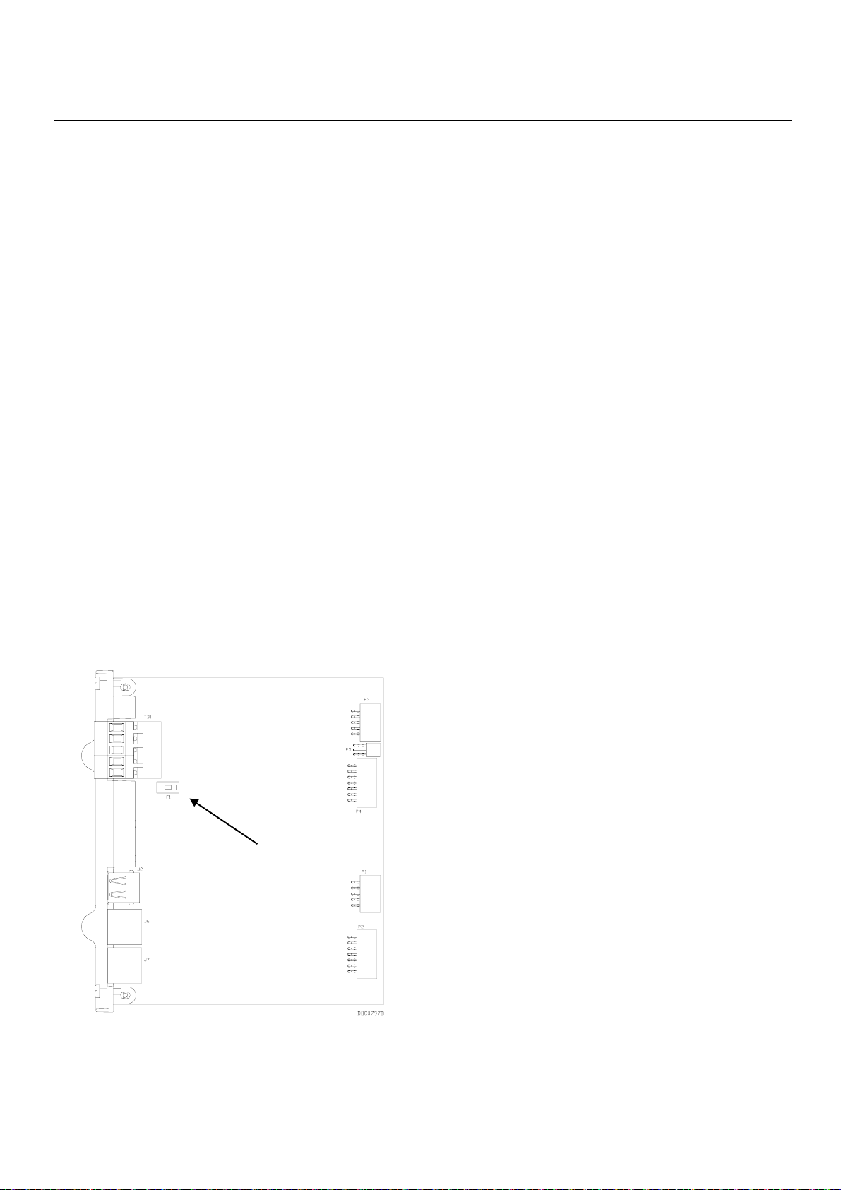
Istruzioni per la sicurezza d'uso – FOUNDATION
Fieldbus Interface
Modulo A6296
Pagina 7
Avvitare ogni filo nella morsettiera. Riposizionare
•
il connettore della morsettiera nella presa.
•
Ricollegare tutte le altre sorgenti di
alimentazione (se necessario) all'FFI.
2. Collegare i cablaggi alle morsettiere sui moduli di
interfaccia H1. Vedere il Capitolo 4 del Manuale di
istruzioni di Foundation Fieldbus Interface (Modulo
A6259) per lo schema e le spiegazioni dei cablaggi.
3. Riposizionare i coperchi sopra le canalette dei cavi al
termine del cablaggio delle morsettiere. Vedere la
Figura 13.
4. Alimentare l'FFI per accendere l'unità. Il LED di
alimentazione dell'FFI (vedere la Figura 13)
dovrebbe diventare di colore verde a indicare che la
tensione applicata è corretta.
5. Una volta avviata l'unità, configurare l'FFI in modo
che sia conforme ai requisiti di applicazione. Fare
riferimento al Manuale di configurazione dell'interfaccia
(Modulo A6250). Durante il normale uso dell'unità
non occorre apportare modifiche al dispositivo.
6. Per una corretta manutenzione dell'FFI, controllare
periodicamente se i cablaggi mostrano segni di
deterioramento.
Sostituzione del fusibile
Se il server non funziona ma si ritiene che sia
alimentato correttamente e il LED di alimentazione non
è acceso, potrebbe essere necessario sostituire il
fusibile da 6,3 A sul modulo CPU (vedere la Figura 12).
1. Scollegare l'alimentazione dal modulo CPU
dell'interfaccia.
2. Rimuovere il coperchio delle canalette dei cavi.
3. Scollegare tutti i cablaggi dal modulo CPU
dell'interfaccia.
4. Svitare le due piccole viti di blocco sulla parte
anteriore della piastra frontale del modulo CPU.
5. Afferrare le linguette sul bordo della piastra
frontale del modulo CPU e sollevare con
delicatezza il modulo CPU estraendolo dalle
prese sulla scheda madre. Si dovrebbe avvertire
il distacco del modulo dalla scheda madre.
6. Rimuovere con cautela il modulo CPU
dall'alloggiamento dell'interfaccia. Evitare di
scalfire i lati della CPU sfregandola contro
l'alloggiamento. Fare attenzione a non tirare i
cavi collegati all'interfaccia.
7. Controllare il fusibile (vedere la Figura 12) e,
se necessario, sostituirlo con un fusibile SB
(Slo-Blo) da 6,3 A MSB.
8. Posizionare il modulo CPU nella rispettiva
canaletta nell'alloggiamento.
9. Far scorrere il modulo CPU verso il basso,
inserendolo nei rispettivi connettori sulla scheda
madre.
10. Avvitare le due piccole viti di blocco sulla parte
anteriore della piastra frontale del modulo CPU.
11. Ricollegare tutti i cablaggi.
12. Riposizionare il coperchio delle canalette dei cavi.
13. Alimentare di nuovo il modulo CPU.
SMONTAGGIO DELL'FFI
1. Eseguire il backup di tutti i dati di configurazione
e di log dell'FFI. Scollegare l'alimentazione
dall'FFI e rimuovere i cablaggi esterni dai moduli
H1.
Fusibile da 6,3 A
2. Togliere il cabinet dell'FFI dalle guide DIN
sbloccando i fermi delle due guide DIN sopra la
parte posteriore dell'alloggiamento.
3. Mettere l'FFI in una scatola per la spedizione o
lo stoccaggio.
Figura 12. Fusibile da 6,3 A della CPU
Page 66

Istruzioni per la sicurezza d'uso – Foundation
Fieldbus Interface
Modulo CPU
dell'FFI
LED di
alimentazione
Modulo A6296
Pagina 8
Coperchi delle
canalette dei
cavi
Moduli H1
Figura 13. F
Bristol, Inc., Bristol Babcock Ltd, Bristol Canada, BBI SA de CV e Flow
Remote Automation Solutions ("RAS"), una divisione di Emerson Process Management. FloBoss, ROCLINK, Bristol, Bristol Babcock, ControlWave, TeleFlow e
Helicoid sono marchi registrati di RAS. AMS, PlantWeb e il logo PlantWeb sono marchi di Emerson Electric Co. Il logo Emerson è un marchio registrato e di servizio
di Emerson Electric Co. Tutti gli altri marchi sono di proprietà dei rispettivi proprietari.
I contenuti di questa pubblicazione sono presentati solo a scopo informativ
queste non costituiscono alcuna garanzia, esplicita o implicita, riguardo ai prodotti o i servizi descritti o il rispettivo uso o applicazione. RAS si riserva il diritto di
modificare o integrare i progetti o le specifiche di tali prodotti in qualsiasi momento e senza preavviso. La vendita di qualsiasi prodotto è regolata dai termini e dalle
condizioni di RAS, disponibili su richiesta. RAS non si assume alcuna responsabilità per la selezione, l'uso o la manutenzione dei prodotti. La selezione, l'uso e la
manutenzione corretta dei prodotti RAS è responsabilità esclusiva dell'acquirente e dell'utente finale.
OUNDATION Fieldbus Interface
Computer Division sono affiliate di proprietà di Emerson Electric Co. che operano come
o. Anche se è stato compiuto ogni sforzo per garantire la precisione delle informazioni,
Emerson Process Management
Remote Automation Solutions
Marshalltown, IA 50158 U.S.A.
Houston, TX 77065 U.S.A.
Pickering, North Yorkshire UK Y018 7JA
© 2011 Remote Automation Solutions, divisione di Emerson Process Management. Tutti i diritti riservati.
Page 67

Instructies voor veilig gebruik – FOUNDATION veldbusinterface
September 2011
FOUNDATION™ veldbusinterface (ROC800-serie)
MODEL W40203
VOEDING: 10 T/M 30 V DC
Document A6296
NOMINAAL VERMOGEN: MAXIMAAL 42 WATT
GEBRUIKSTEMPERATUURBEREIK: -40 T/M +75 °C
Sira 05ATEX4046X
EEx nA IIC T4, -40 °C Tomg +75 °C
MOET WORDEN GEÏNSTALLEERD IN EEN IP54 OF BETERE BEHUIZING OF
SOORTGELIJKE LOCATIE. RAADPLEEG DE INSTRUCTIES VOOR VEILIG
GEBRUIK A6296 VOOR AANVULLENDE SPECIALE OMSTANDIGHEDEN
VOOR VEILIG GEBRUIK EN SPECIFIEKE INSTALLATIE-INSTRUCTIES
VERVANGENDE ZEKERING: 6,3 A TYPE SLO-BLO
WAARSCHUWING: EXPLOSIEGEVAAR – NIET AANSLUITEN/ONTKOPPELEN
TERWIJL CIRCUIT ONDER SPANNING STAAT, TENZIJ BEKEND IS DAT
GEBIED NIET GEVAARLIJK IS.
AMERIKAANSE PATENTEN 6.771.513,
6.542.832 EN 6.912.483
W11361X0012
Afbeelding 1. Typeplaatje F
OUNDATION veldbusinterface
Dit document met instructies voor veilig gebruik is
bedoeld als aanvulling op de Handleiding voor de
OUNDATION veldbusinterface (document A6259). Alle
F
aandachtspunten en omschrijvingen met betrekking tot
de installatie en het verhelpen van storingen vindt u in
deze handleiding. Als u voor dit product scholing nodig
hebt, neem dan contact op met het plaatselijke
verkoopkantoor.
U kunt de Foundation veldbusinterface (of “FFI”) met
ATEX-certificering bestellen bij de H1-segmentmodules
die worden beschreven in de technische specificatie
OUNDATION veldbusinterface (ROC800-serie)
F
(ROC800:FFI).
Speciale voorwaarden voor veilig gebruik van de FFI
Het apparaat dient in een IP54 of betere behuizing
of soortgelijke locatie geïnstalleerd te worden. De
behuizing dient van het juiste certificaat voorzien of
anderszins goedgekeurd te zijn voor de
gebruikszone (zone 2).
Controleer, als het apparaat in een gevaarlijke
omgevi
ng wordt geïnstalleerd, of alle voor de
installatie gebruikte onderdelen geschikt zijn
voor gebruik in een dergelijke omgeving.
Installatie en onderhoud mogen alleen
plaatsvinden als de omgeving daarvoor geen
gevaar oplevert. Installatie of onderhoud in
een gevaarlijke omgeving kan leiden tot
persoonlijk letsel of materiële schade.
Schakel altijd eerst de voeding naar de
Foundation veldbusinterface uit v
oordat u
werkzaamheden aan de bekabeling gaat
uitvoeren. Als de voeding van het apparaat
tijdens werkzaamheden aan de bekabeling
ingeschakeld blijft, kan dit tot lichamelijk
letsel of schade aan het apparaat leiden.
Neem bij werkzaamhedenbinnen in het
apparaat afdoende maatregelen om schade
aan de schakelingen in het apparaat door
elektrostatische ontladingen te voorkomen,
zoals het dragen v
an een geaarde polsband.
Controleer de polariteit van de voedingsspanning voordat u de v
oeding op de
Foundation veldbusinterface aansluit.
Voor het installeren, uitvoeren van onderhoud en
verhelpen van storingen aan het apparaat zijn de
volgende gereedschappen nodig:
®
Personal computer met Microsoft
Windows®
2000 (met Service Pack 2), Windows XP of
Windows Vista.
ROCLINK
™
800 configuratiesoftware.
Kruiskopschroevendraaier.
Rechte schroevendraaier.
De gebruiker dient ervoor te zorgen dat de
gespecificeerde ingangsspanning tijdens bedrijf niet
overschreden zal worden.
Conformiteitsverklaring
Remote Automation Solutions verklaart hierbij dat de
Foundation veldbusinterface voldoet aan de essentiële
vereisten en overige relevante bepalingen van de
Europese richtlijnen 2004/108/EG (EMC) en 1994/9/EG
(ATEX).
Remote Automation Solutions
Website: www.EmersonProcess.com/Remote
D301666X412
Page 68

Instructies voor veilig gebruik – FOUNDATION veldbusinterface
Document A6296
Pagina 2
Specificaties centrale
verwerkingseenheid (CPU)
VOEDING (CPU)
3,56 W bij 24 V DC (toevoer ingang 10 t/m 30 V DC).
MATERIALEN
Huis: acrylnitril-butadieen-styreen (ABS).
Deksels van kabelgoten: polypropyleen.
Modules: thermoplastisch polyester, bestand
tegen oplosmiddelen
OMGEVING
Bedrijfstemperatuur: –40° t/m +7
Opslagtemperatuur: –40° t/m +85°C.
Relatieve luchtvochtigheid: IEC68-2-3;
5–95% niet-condenserend.
Trillingen: IEC68-2-6; 0,15 mm of 20 m/sec
Mechanische schokken: IEC68-2-27; 11
milliseconden, sinusvormig 50 Gs indien niet in
werking, 15 Gs indien in werking
Thermische schokken: IEC68-2-14; lucht-lucht
vanaf –20° t/m 85°C
GEWICHT
Huis, moederkaart en CPU: 1,65 kg
5°C.
2
Specificaties H1-module
VOEDING (CPU)
1,18 W (van interne voedingsconditioner of
externe voeding)
BEVEILIGING TEGEN STROOMPIEKEN
± 36 V DC, veldbusaansluitingen
+ 28 V DC, alarmaansluitingen
GECONDITIONEERD UITGANGSVERMOGEN
18 t/m 24 V DC; maximaal 125 mA;
storingsindicatie bij 150 mA overstroom
AANSLUITING
H1-module met optie van geconditioneerde
voeding: 100 Ω 1%, 1 uF, 50 V.
IMPEDANTIE SEGMENTMODULE
Conformiteit met FF-normen
GEWICHT
100 g
Algemene specificaties
GOEDKEURINGEN
Beoordeeld volgens de volgende Europese
normen (EMC):
EN55011 (emissies).
EN61000-4-2 (Immuniteit voor elektrostatische
ontlading).
EN61000-4-3 (Immuniteit voor elektromagnetische
velden).
EN61000-4-4 (Immuniteit voor snelle elektrische
transiënten).
EN61000-4-6 (Immuniteit t.o.v. geleide velden).
Opmerking: voldoet aan prestatiecriterium B voor
immuniteit
Beoordeeld v
normen (ATEX):
EN50014 (1997) +A1 +A2.
EN60079-15 (2003).
Gecertificeerd door Sira als model W40203.
Markeringen op het product voor gevaarlijke
locaties:
EEx nA IIC T4 – 40°C ≤ T
II 3 G.
Cert. nr. Sira 05ATEX4046X
MONTAGE VAN DE FFI
U kunt de FFI monteren als zelfstandig apparaat of
als integraal onderdeel van een ROC827. De ROC827
ondersteunt maximaal vie
ROC827 al vier moederkaarten bevat, moet u één
moederkaart verwijderen en vervangen door de FFI.
1. De FFI wordt verzonden in een doos. Haal het
apparaat uit de doos. De CPU en de H1-modules
worden in de fabriek geïnstalleerd.
2. Zoek een geschikte plek om de FFI te installeren.
Installeer de FFI altijd in een door de gebruiker
beschikbaar te stellen behuizing, omdat de FFI
beschermd dient te worden tegen rechtstreekse
blootstelling aan regen, sneeuw, ijs, weggeblazen
stof of steentjes en corrosieve omgevingen. Als u
de FFI buiten het gebouw installeert, dient u de
FFI in een IP54-behuizing (of beter) te plaatsen.
Opmerking: dicht alle openingen af die u voor dit
Controleer bij de keuze van de behuizing alle
vrije ruimten. Zorg voor voldoende ruimte voor
het installeren van de bekabeling en het uitvoeren
van onderhoud. Zie Afbeelding 2 en Afbeelding 3.
olgens de volgende Europese
t/m ≤ +75°C)
omg
r moederkaarten. Als de
doel in de behuizing maakt, om de
vereiste IP54-klassering te behouden.
Page 69

Instructies voor veilig gebruik – FOUNDATION veldbusinterface
g
g
Op DIN-rail
emonteerd
Op DIN-rail
emonteerd
Document A6296
Pagina 3
Afbeelding 2. Zijaanzicht van de FFI
Afbeelding 3. Onderaanzicht van de FFI
3. Het huis van de FFI is op twee 35 x 7,5 mm DIN-
rails gemonteerd. Zie Afbeelding 4.
Monteer de bovenste DIN-rail op de FFI.
•
Afbeelding 4. Achterzijde van de FFI
BEDRADING VAN FFI-ONDERDELEN
Voor de bedrading van de FFI moeten de
veldbusapparaten op de H1-modules worden
aangesloten, moeten de H1-modules op de externe
voeding worden aangesloten (indien van toepassing)
en moet de CPU-module van de FFI op de ROC of
op de externe voeding worden aangesloten. Voor dit
document stellen we voor dat u eerst de
veldbusapparaten op de H1-modules aansluit en
vervolgens de FFI op de ROC (of externe voeding)
voordat u de stroom inschakelt.
Opmerking: modules hebben verwijderbare
aansluitingenblokken, zodat u deze
handig kunt bedraden en onderhouden.
Een twisted pair-kabel wordt
aanbevolen voor de bekabeling van
het I/O-signaal. Op de verwijderbare
aansluitingenblokken kan bedrading
van 12-22 AWG worden aangesloten.
Bedrading v
an H1-segmentmodules
• Monteer de onderste DIN-rail op de moederkaart.
• Plaats de FFI op de onderste rail die op de
moederkaart gemonteerd is en zorg ervoor dat
de onderrand van de FFI gelijkligt met het paneel.
• Kantel de bovenkant van de FFI totdat deze
vlak tegen het paneel aan ligt.
• Bevestig de bovenste strip van de DIN-rail aan
het paneel.
Voor bedrading van de H1 PWR-module of de H1module (zonder spanning):
1. Strip het uiteinde van de ader (max. 6,4 mm).
2. Steek het gestripte uiteinde van de ader onder het
klemplaatje onder de aansluitschroef.
3. Draai de schroef vast. Zie Afbeelding 5 of
Afbeelding 6.
Zorg dat er zo min mogelijk ongeïsoleerde draad
blootligt om kortsluiting te voorkomen, maar houd bij
aansluiting wat ruimte over om trekbelasting te
voorkomen.
De FFI ondersteunt maximaal vier van beide typen
H1-segmentmodules. Modules onder spanning
(zie Afbeelding 5) bieden tot 125 mA geconditioneerde
voeding.
Page 70

Instructies voor veilig gebruik – FOUNDATION veldbusinterface
A
A
A
A
A
A
Tabel 2 geeft een identificatie van elke aansluiting en
het doel ervan op de H1-module zonder spanning.
Document A6296
Pagina 4
Voor
FF
veldbus
geschikte
PPARAAT
bedrading
FF
PPARAAT
FF
PPARAAT
DOC0780B
Afbeelding 5. Veldbedrading naar H1-module
onder spanning
Tabel 1 geeft een identificatie van elke aansluiting en het
doel ervan op de H1-module onder spanning.
Tabel 1. Aansluitingen H1-module onder spanning
Aansluiting Typeplaatje Definitie
1 CP+ Gecond itioneerde
2 CP- Geconditioneerde
3 A Veldbus A
4 A Veldbus A
5 A Veldbus A
6 B Veldbus B
7 B Veldbus B
8 B Veldbus B
9 Alarm+ Te hoge
10 Alarm - Aarde
voeding positief
voeding negatief
stroomsterkte
open collector
Gebruik H1-modules zonder spanning en een externe
voor veldbussen geschikte geconditioneerde voeding
(zie Afbeelding 6) wanneer u niet zeker bent van het
stroomverbruik of het aantal veldbusapparaten.
EXTERNE
+
GECONDITIONEERDE VOEDING
-
Voor
veldbus
FF -
PPARAAT
geschikte
bedrading
FF -
PPARAAT
Tabel 2. Aansluitingen H1-module zonder spanning
Aansluiting Typep-
laatje
1 NC G een aans luiting
2 NC G een aans luiting
3 A Veldbus A
4 A Veldbus A
5 A Veldbus A
6 B Veldbus B
7 B Veldbus B
8 B Veldbus B
9 NC G een aans luiting
Definitie
Opmerking: de FFI ondersteunt maximaal vier
H1-modules en u kunt op elke module
maximaal 16 veldbusapparaten
aansluiten. Het werkelijke aantal
ondersteunde apparaten is echter
afhankelijk van het stroomverbruik van
elk apparaat en het type aansluitkabel
dat wordt gebruikt.
Uitschakeling v
an de voedingsconditioner op een
H1 PWR-module
Als u vaststelt dat de voeding die de H1 PWR-module
biedt, onvoldoende is voor uw apparaat, kunt u de
voedingsconditioner op de H1-module uitschakelen en
een externe geconditioneerde voeding gebruiken.
Opmerking: deze optie is alleen beschikbaar voor
een H1 PWR-module. U moet de
voedingsconditioner op de H1 PWRmodule uitschakelen voordat u de
module op een externe voeding
aansluit. Anders kunt u de
voedingsconditioner van de module
onherstelbaar beschadigen.
De voedingsconditioner uitschakelen:
1. Verwijder het deksel van de kabelgoot.
2. Ontkoppel eventuele bedrading naar de
aansluitingenblokken.
3. Schroef de twee borgschroeven los waarmee de
module op zijn plaats gehouden wordt.
4. Pak het plastic lipje aan de rand van de module
stevig vast en trek de module voorzichtig uit de
sleuf. U moet de module mogelijk rustig heen en
weer bewegen.
5. Plaats de module zoals weergegeven in
Afbeelding 7.
FF -
PPARAAT
DOC0779C
Afbeelding 6. Veldbedrading naar H1-module
zonder spanning
Page 71

Instructies voor veilig gebruik – FOUNDATION veldbusinterface
Document A6296
Pagina 5
Jumper P12
(in positie AAN)
Dipswitches
Afbeelding 7. Jumper P12 op H1 PWR-module
6. Verplaats de jumper bij P12 van de tweede en
derde pen (AAN) naar de eerste en tweede pen (UIT).
Opmerking: pas de dipswitchinstellingen op de H1-
module niet aan en wijzig deze ook
niet. De schakelaars zijn in de fabriek
ingesteld op UIT.
7. Leid de module recht in de sleuf in de FFI en schuif
deze in de behuizing totdat de aansluitingen van de
module stevig contact maken met de aansluitingen
op de moederkaart.
8. Draai de borgschroeven op de voorkant van de
module aan.
9. Sluit de bedrading van de module aan.
10. Plaats het deksel van de kabelgoot terug.
Bedrading v
an de CPU-module van de FFI
Tabel 3. Aansluitingen CPU-m
Aansluiting Typeplaatje Definitie
TB1 – 1 AARDE Aarde
TB1 – 2 A
TB1 – 3 B
TB1 – 4 + Voeding positief
TB1 – 5 –
6 USB Voeding negatief
7 1 Ethernetpoort
8 2 Ethernetpoort
Momenteel niet
gebruikt
Momenteel niet
gebruikt
Power Input
Negative
odule
Bedrading op het verwijderbare blok met
klemaansluitingen op de CPU-module aansluiten:
1. Strip het uiteinde van de ader (max. 6,4 mm).
2. Steek het gestripte uiteinde van de ader onder het
klemplaatje onder de losgedraaide aansluitschroef.
3. Draai de schroef vast.
U kunt de FFI als integraal onderdeel van een
ROC827 of als zelfstandig apparaat aansluiten.
Opmerking: aansluiting van de FFI op de ROC800
(“integrale aansluiting”) verdient de
voorkeur, want het garandeert dat als
de voeding van de CPU van de
ROC800 CPU wordt uitgeschakeld,
ook de voeding van de FFI wordt
uitgeschakeld.
VOEDING
VOEDT
WAARSCHUWING: TEMPERATUURCODE, T4. GEBRUIK DE USB-AANSLUITING
ALLEEN ALS BEKEND IS DAT DE LOCATIE NIET GEVAARLIJK IS.
Afbeelding 8. Aansluitingen voor bedrading
van de CPU-module
Tabel 3 geeft een identificatie van elke aansluiting en het
doel ervan in de CPU-module.
Bedrading van de FFI als integraal onderdeel van
een ROC827
Schuif de FFI in de behuizing van de ROC827
(zoals weergegeven in Afbeelding 9).
Afbeelding 9. FFI in ROC827 geschoven
Opmerking: de ROC827 ondersteunt maximaal
er moederkaarten. Als de ROC827 al
vi
vier moederkaarten bevat, moet u één
moederkaart verwijderen en vervangen
door de FFI.
Page 72

Instructies voor veilig gebruik – FOUNDATION veldbusinterface
EXTERNE
VOEDING
EXTERNE
VOEDING
VOEDING
EXTERNE
Document A6296
Pagina 6
Afbeelding 10 geeft een FFI weer die stroom krijgt van
een ROC800. Voor communicatie met de ROC800 en
het netwerk worden de Ethernetaansluitingen op de FFI
gebruikt.
STORING
VOEDING
VOEDT
VOEDT
CODES
LICENTIE-
WAARSCHUWING: TEMPERATUURCODE, T4. GEBRUIK DE USB-AANSLUITING
ALLEEN ALS BEKEND IS DAT DE LOCATIE NIET GEVAARLIJK IS.
Afbeelding 10. Integrale bedrading van de FFI
Bedrading van de FFI als zelfstandig apparaat
Als u besluit de FFI als zelfstandig apparaat te
configureren, gescheiden van een ROC800, moet u de
FFI op een eigen voeding aansluiten. Zie Afbeelding 11.
AARDING VAN DE FFI
Als in uw bedrijf geen specifieke aardingseisen gelden,
installeert u de FFI als een "zwevend" (niet op de
aarde aangesloten) systeem. Volg anders de
specifieke aardingsvoorschriften van uw bedrijf.
Als u echter een geaard apparaat op een (RS-485)poort van de FFI EIA-485 aansluit, dient u de
voedingsbron van de FFI te aarden.
Volg de onderstaande richtlijnen als u het apparaat
moet aarden:
• Als het apparaat een gelijkspanningsbron
gebruikt, moet de aarding bij het uitschakelpunt
eindigen. Alle aarddraden van het apparaat met inbegrip van de kabels of leidingen met
stroomdraden - dienen een ononderbroken pad
naar het uitschakelpunt te volgen.
• Een verkeerde of onvoldoende aarding kan vaak
storingen veroorzaken, zoals het vormen van
aardlussen in het systeem. Door een correcte
aarding van de FFI worden de effecten van
elektrische stoorsignalen gereduceerd en wordt
het apparaat beschermd tegen blikseminslag.
Installeer een overspanningsbeveiliging bij het
uitschakelpunt van gelijkspanningsbronnen om
de geïnstalleerde apparatuur te beschermen
tegen blikseminslag en piekspanningen. Het
verdient mogelijk ook aanbeveling om een
overspanningsbeveiliging voor de
inbelmodemkaart te monteren.
Sluit de voedingsbekabeling aan. Bepaal de
voedingsvereisten zoals beschreven in Hoofdstuk 3
van de handleiding van de Foundation
veldbusinterface (document A6259).
STORING
VOEDING
CODES
LICENTIE-
VOEDT
VOEDT
WAARSCHUWING: TEMPERATUURCODE, T4. GEBRUIK DE USB-AANSLUITING
ALLEEN ALS BEKEND IS DAT DE LOCATIE NIET GEVAARLIJK IS.
Afbeelding 11. Zelfstandige bedrading van de FFI
Polariteit v
an de aansluiting controleren
1. Voor het aansluiten van de gelijkspanningsvoeding:
• Volg, indien nodig, de procedure voor het
maken van een back-up van de configuratieen logdata.
• Installeer anders een overspanningsbeveiliging
bij het uitschakelpunt.
• Verwijder alle andere voedingsbronnen van
de ROC800.
• Monteer een zekering bij de ingangsvoeding.
• Haal de connector van het aansluitingenblok
uit de bus.
• Steek het gestripte uiteinde van elke kabel in
de klem onder de relevante BAT+ / BAT–
aansluitschroef (voor de bron van 12 Volt DC)
OF in de klem onder de relevante +/–
-aansluitschroef (voor de bron van 24 Volt DC).
Opmerking: de + aansluitschroef zou ook
een zekering moeten hebben.
Page 73

Instructies voor veilig gebruik – FOUNDATION veldbusinterface
Document A6296
Pagina 7
• Schroef elke ader in het aansluitingenblok vast.
Steek de connector van het aansluitingenblok
weer in de bus.
• Plaats (indien nodig) alle andere
voedingsbronnen terug in de FFI.
2. Sluit de bedrading op de aansluitingenblokken op de
H1-interfacemodules aan. Zie Hoofdstuk 4 van de
Handleiding Foundation veldbusinterface (document
A6259) voor bedradingsschema's en de
bijbehorende uitleg.
3. Druk de deksels op de kabelgoten zodra u klaar bent
met het aansluiten van de bekabeling op de
aansluitingenblokken. Zie Afbeelding 13.
4. Schakel de stroom in om de FFI te starten. Het LED-
lampje voor aan/uit op de FFI (zie Afbeelding13) zou
groen moeten gaan branden als indicatie dat de
aangesloten spanning correct is.
5. Zodra het apparaat opgestart is, moet de FFI
geconfigureerd worden volgens de vereisten van de
toepassing. Raadpleeg de Gebruikershandleiding
configuratie veldinterface (document A6250). Bij
normaal bedrijf en gebruik hoeft de gebruiker het
apparaat niet bij te stellen.
1. Ontkoppel de voeding van de interface van de
CPU-module.
2. Verwijder het deksel van de kabelgoot.
3. Ontkoppel alle bedrading van de interface van de
CPU-module.
4. Schroef de vier bevestigingsschroefjes aan de
voorzijde van de voorplaat van de CPU-module los.
5. Pak de optillipjes aan de rand van de voorplaat
van de CPU-module vast en til de CPU-module
voorzichtig uit de aansluitingen op de moederplaat.
U moet de module los voelen komen van de
moederplaat.
6. Haal de CPU-module voorzichtig uit de
interfacebehuizing. Schraap niet met de zijkanten
van de CPU langs de behuizing. Zorg dat u geen
kabels lostrekt die op de interface zijn aangesloten.
7. Onderzoek de zekering (zie Afbeelding 12) en
vervang deze indien nodig door een MSB 6,3A
SB (Slo-Blo) zekering.
8. Plaats de CPU-module in de daartoe bestemde
sleuf in de behuizing.
6. Als onderhoud van de FFI dient de bekabeling
regelmatig op tekenen van slijtage te worden
gecontroleerd.
De zekering vervangen
Als de server niet functioneert, maar u denkt dat deze
op de voeding is aangesloten en het LED-lampje
AAN/UIT niet gaat branden, moet u mogelijk de
zekering van 6,3 A op de CPU-module vervangen
(zieAfbeelding 12).
Zekering van 6,3 A
9. Schuif de CPU-module omlaag in de daartoe
bestemde aansluitingen op de moederkaart.
10. Schroef de vier bevestigingsschroefjes aan de
voorzijde van de voorpl
t.
vas
aat van de CPU-module
11. Sluit alle bedrading weer aan.
12. Plaats het deksel van de kabelgoot terug.
13. Sluit de CPU-module weer op de voeding aan.
DEMONTAGE VAN DE FFI
1. Maak een back-up van alle configuratie- en
logboekgegevens van de FFI. Koppel vervolgens
alle voedingsbronnen van de FFI los en verwijder
alle externe bedrading van de H1-modules.
2. Haal het huis van de FFI van de DIN-rails door
de twee vergrendelingen van de DIN-rail boven
aan de achterzijde van het huis los te maken.
3. Plaats de FFI voor verzending of opslag in een
doos.
Afbeelding 12. Zekering van 6,3 A op CPU
Page 74

Instructies voor veilig gebruik – Foundation veldbusinterface
Deksels van
kabelgoten
CPU-module
van FFI
H1-modules
Voedings-
LED
Document A6296
Pagina 8
Afbeelding 13. F
Bristol, Inc., Bristol Babcock Ltd, Bristol Canada, BBI SA de CV en de Flow
drijven onder de naam Remote Automation Solutions ("RAS"), een divisie van Emerson Process Management. FloBoss, ROCLINK, Bristol, Bristol Babcock, ControlWave,
TeleFlow en Helicoid zijn handelsmerken van RAS. AMS, PlantWeb en het PlantWeb-logo zijn handelsmerken van Emerson Electric Co. Het Emerson-logo is een
handels- en servicemerk van Emerson Electric Co. Alle andere merken zijn eigendom van hun respectieve eigenaren.
De inhoud van deze publicatie is uitsluitend ter informatie. Hoewel w
of garanties, expliciet of impliciet, met betrekking tot de producten of diensten die erin beschreven zijn, of het gebruik of de toepasbaarheid ervan, aan worden ontleend. RAS
behoudt zich het recht voor om de ontwerpen en specificaties van dergelijke producten zonder voorafgaand bericht te wijzigen of te verbeteren. De leveringsvoorwaarden
van RAS, die op aanvraag verkrijgbaar zijn, zijn op alle verkopen van toepassing. RAS aanvaardt geen aansprakelijkheid voor de selectie, het gebruik of het onderhoud van
enig product. De aansprakelijkheid voor de juiste selectie, het juiste gebruik en onderhoud van enig product van RAS, berust uitsluitend bij de koper en de eindgebruiker.
OUNDATION veldbusinterface
Computer Div
e uiterste zorg hebben besteed aan de nauwkeurigheid van de informatie, kunnen er geen rechten
ision zijn volle dochtermaatschappijen van Emerson Electric Co., die handel
Emerson Process Management
Remote Automation Solutions
Marshalltown, IA 50158 U.S.A.
Houston, TX 77065 U.S.A.
Pickering, North Yorkshire UK Y018 7JA
© 2011 Remote Automation Solutions, divisie van Emerson Process Management. Alle rechten voorbehouden.
Page 75

Instrucciones de seguridad para el uso –
Interfaz de F
OUNDATION Fieldbus
Formulario A6296
Septiembre de 2011
FOUNDATION™ Fieldbus Interface (Serie ROC800)
MODELO W40203
POTENCIA DE ENTRADA: 10 A 30 VCC
RÉGIMEN DE POTENCIA: MÁXIMO 42 WATTS
TEMPERATURA AMBIENTE OPERATIVA: -40 A +75 °C
Slra 05ATEX4046X
EEx nA IIC T4, -40 °C Tamb +75 °C
DEBE INSTALARSE EN UN IP54, UN GABINETE DE MEJOR CALIDAD O
UNA UBICACIÓN EQUIVALENTE. CONSULTE LAS INSTRUCCIONES DE
SEGURIDAD A6296 PARA VER LAS CONDICIONES ADICIONALES DE USO
SEGURO Y LAS INSTRUCCIONES ESPECÍFICAS PARA LA INSTALACIÓN
CAMBIO DE FUSIBLES: TIPO 6.3 AMP SLO-BLO
ADVERTENCIA: PELIGRO DE EXPLOSIÓN – NO CONECTE NI
DESCONECTE MIENTRAS EL CIRCUITO ESTÉ ACTIVO, A MENOS QUE
SE TRATE DE UN ÁREA NO PELIGROSA.
PATENTE ESTADOUNIDENSE 6,771,513,
6,542,832 Y 6,912,483
DOC0888B
Figura 1. Etiqueta de
FOUNDATION Fieldbus Interface
Utilice este documento de instrucciones de seguridad
para el uso (SUI) con el Manual de instrucciones de
OUNDATION Fieldbus Interface (Formulario A6259).
F
Consulte el manual para obtener información completa
sobre advertencias y procedimientos de instalación y
resolución de problemas. Si necesita recibir
capacitación sobre este producto, comuníquese con la
oficina de ventas de su zona.
Foundation Fieldbus Interface (o “FFI”), aprobado por
ATEX, se puede solicitar con los módulos del segmento
H1 detallados en las especificaciones técnicas de
OUNDATION Fieldbus Interface (Serie ROC800)
F
(ROC800:FFI).
Condiciones de seguridad especiales para el uso de FFI
Instale el equipo en un IP54 o gabinete de mejor
calidad o ubicación equivalente. Cualquier gabinete
deberá contar con la certificación o aprobación
correspondiente a su zona de uso (Zona 2).
Cuando instale unidades en un área
peligrosa, controle que todos los
componentes estén rotulados para utilizarse
en ese tipo de lugares. La instalación y el
mantenimiento deben realizarse sólo cuando
no existen riesgos en la zona. Si realiza las
tareas de instalación o mantenimiento dentro
de las zonas de riesgo podrían producirse
accidentes y daños en los bienes materiales.
Desenchufe siempre la interfaz Foundation
Fieldbus antes de conectar cualquier tipo de
cables. Si manipula cables con carga
eléctrica podrían producirse accidentes y
daños en los bienes materiales.
Para evitar daños en los circuitos cuando
trabaje en la unidad, tome las precauciones
adecuadas contra descargas electrostáticas
(por ejemplo, utilice una muñequera
antiestática).
Verifique la polaridad de la energía de entrada
antes de conectar la interfaz Foundation
Fieldbus.
Las siguientes herramientas son necesarias para la
instalación, el mantenimiento y la resolución de
problemas:
Computadora personal con Microsoft
2000 (con Service Pack 2), Windows XP o
Windows Vista.
Software de configuración ROCLINK
Destornillador Phillips.
Destornillador plano.
PRECAUCIÓN
PRECAUCIÓN
®
™
Windows®
800.
El usuario deberá asegurarse de que no se supere
la tensión nominal de entrada en funcionamiento.
Declaración de conformidad
Por el presente, Remote Automation Solutions declara
que los productos Foundation Fieldbus Interface
cumplen con los requisitos fundamentales y otras
disposiciones relevantes de las directivas europeas
2004/108/EC (EMC) y 1994/9/EC (ATEX).
División Remote Automation Solutions
Sitio Web: www.EmersonProcess.com/Remote
D301666X412
Page 76

Instrucciones de seguridad para el uso –
Interfaz de F
OUNDATION Fieldbus
Formulario A6296
Página 2
Especificaciones del sistema CPU
ENERGÍA (CPU)
3,56 W a 24 V CC (suministro de entrada de 10 a
30 V CC).
MATERIALES
Gabinete: plástico acrilonitrilo butadieno estireno
(ABS).
Cubierta del canal de cableado: plástico
polipropileno.
Módulos: poliéster termoplástico, resistente al
solvente.
CARACTERÍSTICAS AMBIENTALES
Temperatura de funcionamiento: –40° a
+75°C.
Temperatura de almacenamiento: –40° a
+85°C.
Humedad relativa: IEC68-2-3; 5 a 95% sin
condensación.
Vibración: IEC68-2-6; 0,15 mm o 20 m/seg.
Choque mecánico: IEC68-2-27; 11
milisegundos, sinusoide 50Gs apagado, 15 Gs
encendido
Choque térmico: IEC68-2-14; aire a aire de –
20° a 85°C
PESO
Carcasa, panel de fondo y CPU: 1,65 kg.
2
Especificaciones del módulo H1
ENERGÍA (CPU)
1,18 W (del acondicionador de alimentación
interna o fuente de alimentación externa)
PROTECCIÓN CONTRA EXCESOS DE
VOLTAJE
± 36 V dc, conexiones fieldbus
+ 28 V dc, conexiones para alarmas
SALIDA DE CORRIENTE ACONDICIONADA
18 a 24 V dc; 125 mA máximo; 150 mA
indicación de falla por sobrecorriente
TERMINADOR
Módulo H1 con opción de energía condicionada:
100 Ω 1%, 1 uF, 50 V.
IMPEDANCIA DEL MÓDULO DEL SEGMENTO
Cumple con las normas FF
PESO
100 g
Especificaciones comunes
APROBACIONES
Evaluado según las siguientes normas europeas
(EMC):
EN55011 (Emisiones).
EN61000-4-2 (protección contra descarga
electrostática).
EN61000-4-3 (protección contra campos
electromagnéticos).
EN61000-4-4 (protección contra descarga eléctrica
transitoria rápida).
EN61000-4-6 (protección contra las perturbaciones
conducidas).
Nota: cumple con el Criterio B de rendimiento en lo
que respecta a protección.
Evaluado según las siguientes normas europeas
(ATEX):
EN50014 (1997) +A1 +A2.
EN60079-15 (2003).
Certificado por Sira como modelo W40203.
Clasificaciones de productos para lugares
peligrosos:
EEx nA IIC T4 – 40°C ≤ T
II 3 G.
Certificación catálogo Sira 05ATEX4046X
MONTAJE DEL FFI
Puede instalar el FFI como una unidad
independiente o como pieza integral de un ROC827.
El ROC827 es compatible con un máximo de cuatro
paneles de fondo. Si el ROC827 ya incluye cuatro
paneles de fondo, debe extraer un panel de fondo y
reemplazarlo con el FFI.
1. La unidad FFI se entrega dentro de una caja.
Retire la unidad de la caja. La CPU y los módulos
H1 se instalan en la fábrica.
2. Busque un lugar apropiado para instalar el
equipo FFI. Instale siempre el FFI en el gabinete
que se entrega al usuario, dado que el FFI
necesita protección contra la exposición directa a
la lluvia, la nieve, el hielo, el polvo o los residuos
que flotan en el ambiente y elementos corrosivos
de la atmósfera. Si instala el FFI fuera de un
edificio, coloque el FFI en un gabinete IP54 (o de
mejor calidad).
Nota: selle los orificios que realice para ello en el
gabinete, a fin de garantizar que se
mantenga la calidad requerida para el IP54.
Cuando se disponga a elegir un lugar para la
instalación, verifique todas las distancias. Debe
contar con el espacio adecuado para el cableado
y el servicio técnico. Ver Figura 2 y Figura 3.
a ≤ +75°C)
amb
Page 77

Instrucciones de seguridad para el uso –
Interfaz de F
OUNDATION Fieldbus
Instalación del
riel DIN
[9,51]
Instalación del
riel DIN
Formulario A6296
Página 3
Figura 2. Vista lateral del FFI
[6,85]
Figura 3. Vista inferior del FFI
3. La carcasa del FFI se instala sobre dos rieles DIN
de 35 x 7,5 mm. Consulte la Figura 4.
• Instale los rieles DIN superiores sobre el FFI.
• Instale los rieles DIN inferiores sobre el panel
de fondo.
• Coloque el FFI sobre el riel inferior instalado en
el panel de fondo, asegurándose de que el
borde inferior del FFI esté nivelado con el
panel.
• Haga girar la parte superior de la unidad FFI
hasta nivelarla con el panel.
• Asegure la barra superior del riel DIN al panel.
Figura 4. Vista posterior del FFI
CABLEADO DE LOS COMPONENTES DEL FFI
El cableado del FFI incluye la conexión de los
dispositivos de fieldbus a los módulos H1, el
cableado de los módulos H1 a la alimentación
externa (si corresponde) y el cableado del módulo
de la CPU del FFI al ROC o fuente de alimentación
externa. En este documento, le recomendamos que
en principio realice el cableado de los dispositivos
fieldbus a los módulos H1 y que luego realice el
cableado del FFI al ROC (o fuente de alimentación
externa) antes de aplicar corriente eléctrica.
Nota: los módulos incluyen bloques de terminales
desmontables para facilitar el cableado y el
servicio técnico. Se recomienda el cable de
par trenzado para el circuito de señalización
de E/S. Los bloques de terminales
desmontables utilizan cables de calibre 12-22.
Cableado de los módulos del segmento H1
Para realizar el cableado de los módulos H1 PWR o
H1 (carga eléctrica desconectada):
1. Pele el extremo del cable (6,4 mm. como
máximo).
2. Inserte el extremo descubierto en la abrazadera
ubicada debajo del tornillo de terminal.
3. Ajuste los tornillos. Ver Figura 5 o Figura 6.
Deje expuesta una pequeña porción de cable
descubierta a fin de evitar cortocircuitos, pero al hacer
las conexiones permita un poco de juego en los cables
a fin de evitar la tensión.
El FFI es compatible con cuatro tipos de módulos de
segmentos H1. Los módulos con carga eléctrica
Page 78

Instrucciones de seguridad para el uso –
g
Interfaz de F
OUNDATION Fieldbus
Formulario A6296
Página 4
(consulte la Figura 5) ofrecen hasta 125 mA de corriente
acondicionada.
Fieldbuscableado
aprobado
Alarma
DOC0780B
Figura 5. Cableado del sitio para el módulo H1 con
carga eléctrica
La tabla 1 identifica a cada terminal y su uso para el
módulo H1 con carga eléctrica.
Tabla 1. Terminales del módulo H1 con carga eléctrica
Terminal Etiqueta Definición
1 CP+
2 CP-
3 A Fieldbus A
4 A Fieldbus A
5 A Fieldbus A
6 B Fieldbus B
7 B Fieldbus B
8 B Fieldbus B
9 Alarma+
10 Alarma+ Puesta a tierra
Corriente
acondiciona da
positiva
Corriente
acondiciona da
ne
ativa
Sobrecorriente
Colector abierto
Use los módulos H1 sin carga eléctrica y una fuente de
alimentación externa acondicionada aprobada para
fieldbus (consulte la Figura 6) si desconoce el consumo
de energía o la cantidad de dispositivos fieldbus.
Fieldbuscableado
aprobado
DISPOSITIVO
FF
DISPOSITIVO
FF
DISPOSITIVO
FF
+
CORRIENTE
ACONDICIONADA
EXTERNA
-
DISPOSITIVO
FF
DISPOSITIVO
FF
La tabla 2 identifica a cada terminal y su uso para el
módulo H1 sin carga eléctrica.
Tabla 2. Terminales del módulo H1 sin carga eléctrica
Terminal Etiqueta Definición
1 NC Sin conexión
2 NC Sin conexión
3 A Fieldbus A
4 A Fieldbus A
5 A Fieldbus A
6 B Fieldbus B
7 B Fieldbus B
8 B Fieldbus B
9 NC Sin conexión
10 NC Sin conexión
Nota: el FFI es compatible con un máximo de
cuatro módulos H1 y usted puede conectar
hasta 16 dispositivos fieldbus a cada módulo.
Sin embargo, la cantidad actual de
dispositivos compatibles depende del
consumo de energía de cada uno y del tipo
de cable que se utilice para la conexión.
Desactivación del acondicionador de alimentación
en un módulo H1 PWR
Si determina que la cantidad de energía que proviene
del módulo H1 PWR no es suficiente para su
dispositivo, puede desactivar el acondicionador de
alimentación en el módulo H1 y usar energía
acondicionada externa.
Nota: esta opción se encuentra disponible
únicamente para un módulo H1 PWR. Usted
debe desactivar el acondicionador de
alimentación en el módulo H1 PWR antes de
conectar los cables del módulo con la fuente
de alimentación externa. De lo contrario,
puede dañar de manera irreparable el
acondicionador de alimentación del módulo.
Para deshabilitar la corriente acondicionada:
1. Extraiga la tapa del canal de cableado.
2. Desconecte los cables de los bloques de
terminales.
3. Retire los dos tornillos prisioneros que sujetan al
módulo en su sitio.
4. Tome firmemente el reborde plástico sobre el
borde del módulo y tire con sumo cuidado el
módulo de la ranura. Es probable que deba
mover el módulo con cuidado.
5. Ubique el módulo como se indica en la Figura 7.
DISPOSITIVO
DOC0779C
Figura 6. Cableado del sitio para el módulo H1 sin carga
eléctrica
FF
Page 79

Instrucciones de seguridad para el uso –
A
)
Interfaz de F
Figura 7. Puente P12 en el módulo H1 PWR
6. Mueva el puente ubicado en P12 desde el segundo
y tercer pin (ENCENDIDO) al primer y segundo pin
(APAGADO).
Nota: no ajuste ni cambie la configuración del
interruptor DIP en el módulo H1. Los
interruptores están configurados de fábrica
como APAGADOS.
7. Alinee el módulo en su correspondiente ranura en
el FFI y deslícelo en el gabinete hasta que los
conectores del módulo contacten de manera segura
a los conectores del panel de fondo.
8. Ajuste los tornillos prisioneros en el frente del módulo.
9. Realice el cableado del módulo.
10. Coloque nuevamente la tapa del canal de cableado.
Cableado del módulo CPU del FFI
OUNDATION Fieldbus
Puente P12
(en posición
ENCENDIDO
Interruptores
PAGADO
ENCENDIDO
DIP
Formulario A6296
Página 5
Terminal Etiqueta Definición
TB1 – 1 TIERRA Conexión a tierra
TB1 – 2 A
TB1 – 3 B
TB1 – 4 +
TB1 – 5 –
6 USB
7 1 Puerto Ethernet
8 2 Puerto Ethernet
Actualmente no
se utiliza
Actualmente no
se utiliza
Potencia de
entrada positiva
Potencia de
entrada negativa
Actualmente no
se utiliza
A fin de conectar los cables en las terminales de los
bloques de compresión extraíbles en el módulo CPU:
1. Pele el extremo del cable (6,4 mm. como máximo).
2. Inserte el extremo descubierto en la abrazadera
ubicada debajo del tornillo de terminal que se ha
aflojado.
3. Ajuste los tornillos.
Puede conectar los cables del FFI como pieza
integral de un ROC827 o como un dispositivo
independiente.
Nota: se recomienda realizar el cableado del FFI al
ROC800 (“cableado integral”), dado que
garantiza que también se interrumpa el
suministro del FFI al interrumpir el suministro
eléctrico de la CPU de ROC800.
FUENTE
ENERGIAS
ADVERTENCIA: CÓDIGO DE TEMPERATURA, T4. NO UTILICE
CONECTORES USB A MENOS QUE SE TRATE DE UN ÁREA SIN PELIGRO.
Figura 8. Terminales de cableado del módulo CPU
La tabla 3 identifica a cada terminal y su uso en el
módulo CPU.
Tabla 3. Terminales del módulo CPU
Cableado del FFI como pieza integral de un ROC827
Inserte el FFI en la carcasa del ROC827 (como se
indica en la Figura 9).
Figura 9. FFI insertado en ROC827
Nota: el ROC827 es compatible con un máximo de
cuatro paneles de fondo. Si el ROC827 ya
incluye cuatro paneles de fondo, debe
extraer un panel de fondo y reemplazarlo con
el FFI.
Page 80

Instrucciones de seguridad para el uso –
Interfaz de F
OUNDATION Fieldbus
Formulario A6296
Página 6
La Figura 10 muestra un FFI que toma el suministro
eléctrico de un ROC800. Las comunicaciones
realizadas al ROC800 y a la red utilizarán las
conexiones de Ethernet en el FFI.
CONEXIONES
ELÉCTRICAS
EXTERNAS
VOFF
VOVER
TEMP.
ANOMALÍA
CPU
ETHERNET
Indicador
ESTADO DE
RESTABLECER
LED
LICENCIA
CLAVES DE
COL TX RX
VÍNCULO
FUENTE
ENERGIAS
ADVERTENCIA: CÓDIGO DE TEMPERATURA, T4. NO UTILICE
CONECTORES USB A MENOS QUE SE TRATE DE UN ÁREA SIN PELIGRO.
ADVERTENCIA: CÓDIGO DE TEMPERATURA, T4. NO UTILICE
CONECTORES USB A MENOS QUE SE TRATE DE UN ÁREA SIN PELIGRO.
Figura 10. Cableado integral del FFI
Cableado del FFI como un dispositivo
independiente
Si decide configurar el FFI como dispositivo
independiente de un ROC800, debe conectar los cables
del FFI a su propia fuente de alimentación. Ver Figura 11.
CONEXIONES
ELÉCTRICAS
EXTERNAS
VOFF
VOVER
TEMP.
FANOMALÍA
CPU
ETHERNET
Indicador
LED
ESTADO DE
LICENCIA
CLAVES DE
RESETAR
COL TX RX
VÍNCULO
FUENTE
ENERGIAS
ADVERTENCIA: CÓDIGO DE TEMPERATURA, T4. NO UTILICE
CONECTORES USB A MENOS QUE SE TRATE DE UN ÁREA SIN PELIGRO.
CONEXIONES
ELÉCTRICAS
EXTERNAS
Figura 11. Cableado independiente del FFI
PUESTA A TIERRA DE LA UNIDAD FFI
Si su empresa no establece requisitos específicos
para la puesta a tierra, instale el FFI como un
sistema “flotante” (sin conexión a tierra). De lo
contrario, respete las indicaciones específicas sobre
la puesta a tierra que establece su empresa. Sin
embargo, si realiza una conexión entre un
dispositivo con puesta a tierra y un puerto EIA-485
(RS-485) del FFI, conecte la puesta a tierra de la
fuente de alimentación del FFI.
Si debe conectar la puesta a tierra del equipo,
respete las siguientes indicaciones:
• Cuando el equipo utiliza una fuente de tensión de
CC, el sistema de puesta a tierra debe terminar en
el interruptor del servicio. Todos los conductores
de puesta atierra de los equipos (entre ellos, los
cables o conductos que transportan los
conductores de alimentación eléctrica) deben
suministrar un trayecto ininterrumpido de
alimentación eléctrica al interruptor del servicio.
• Las conexiones de puesta a tierra inadecuadas
o deficientes pueden causar problemas, como
por ejemplo, introducir bucles de tierra en el
sistema. La correcta conexión a tierra de FFI
ayuda a reducir los efectos del ruido eléctrico
durante el funcionamiento y ofrece protección
contra rayos. Debe instalarse un dispositivo de
protección de sobrecarga en el interruptor de
servicio de los sistemas de fuentes de CC para
proteger a los equipos instalados contra rayos y
sobrecargas de energía. Asimismo, se puede
utilizar un protector de sobrecarga telefónica
para la tarjeta de comunicación con módem de
acceso telefónico.
Conecte el equipo al suministro eléctrico. Determine
los requisitos de alimentación que se detallan en el
Capítulo 3 del Manual de instrucciones de
Foundation Fieldbus Interface (Formulario A6259).
Verificar la polaridad de la conexión
4. Para realizar las conexiones de suministro
eléctrico de CC.
• Complete el procedimiento de respaldo de la
configuración y los datos de registro, si
corresponde.
• Instale un dispositivo de protección de
sobrecarga en el interruptor del servicio de
forma opcional.
• Extraiga todas las fuentes de alimentación
restantes del ROC800.
• Instale un fusible en la fuente de
alimentación de entrada.
• Extraiga el conector del bloque de la terminal
del tomacorriente.
• Puede insertar el extremo descubierto de cada
cable en la abrazadera ubicada debajo del
Page 81

Instrucciones de seguridad para el uso –
Interfaz de F
tornillo de terminal BAT+ / BAT– (para la fuente de
CC de 12 voltios) O en la abrazadera ubicada
debajo del tornillo de terminal +/- (para la fuente de
CC de 24 voltios).
Nota: la terminal + también deberá tener un
• Atornille cada cable en el bloque de la terminal.
Enchufe el conector del bloque de la terminal
nuevamente en el tomacorriente.
OUNDATION Fieldbus
fusible.
Formulario A6296
Página 7
• Coloque nuevamente el resto de las fuentes de
alimentación (si fuera necesario) en el FFI.
5. Conecte los cables a los bloques de las terminales
en los módulos de la interfaz H1. Consulte el
Capítulo 4 del Manual de instrucciones de
Foundation Fieldbus Interface (Formulario A6259)
para ver el esquema de cableado y las
explicaciones.
6. Presione las cubiertas de los canales de cableado
en su sitio sobre los canales de cableado, una vez
finalizado el cableado de los bloques de las
terminales. Ver Figura 13.
7. Suministre energía para iniciar el FFI. El indicador
LED de alimentación en el FFI (consulte la Figura
13) debería estar encendido en la luz verde para
indicar que el voltaje aplicado es correcto.
8. Cuando la puesta en marcha se realice
correctamente, configure el FFI de acuerdo con los
requisitos de la aplicación. Consulte el Manual del
usuario del configurador de la interfaz del sitio
(Formulario A6250). Durante el funcionamiento y uso
normales, no es necesario realizar modificaciones
para los usuarios en este dispositivo.
9. Para mantener el FFI, revise el cableado de forma
periódica para detectar signos de deterioro.
Reemplazo de los fusiles
Si el servidor no funciona, si bien considera que recibe
alimentación eléctrica y la luz de ENCENDIDO – LED no
enciende, es probable que deba reemplazar el fusible de
6,3 amp en el módulo de la CPU (consulte la Figura 12).
1. Interrumpa el suministro eléctrico del módulo de la
interfaz de la CPU.
2. Extraiga la tapa del canal de cableado.
3. Desconecte todos los cables del módulo de la
interfaz de la CPU.
4. Retire los dos tornillos de retención pequeños del
frente de la placa frontal del módulo de la CPU.
5. Tome las lengüetas verticales en el borde de la
placa frontal del módulo de la CPU y con sumo
cuidado levante el módulo de la CPU hacia afuera de
sus enchufes en el panel de fondo. Debe sentir que
el módulo se desprende del panel de fondo.
Fusible de 6,3
Amp
Figura 12. Fusible de la CPU de 6,3 Amp
6. Con sumo cuidado, extraiga el módulo de la CPU
de la carcasa de la interfaz. No raspe los
laterales de la CPU con la carcasa. Asegúrese
de no tirar de los cables conectados a la interfaz.
7. Revise el fusible (consulte la Figura 12) y, de ser
necesario, reemplácelo con un fusible MSB 6,3A
SB (Slo-Blo).
8. Coloque el módulo de la CPU en el canal
correspondiente en la carcasa.
9. Deslice el módulo de la CPU hacia abajo en sus
conectores en el panel de fondo.
10. Ajuste los dos tornillos de retención pequeños
del frente de la placa frontal del módulo de la
CPU.
11. Conecte nuevamente todos los cables.
12. Reemplace la tapa del canal de cableado.
13. Restablezca el suministro eléctrico en el módulo
de la CPU.
DESMONTAJE DEL FFI
1. Realice el respaldo de toda la configuración y
de los datos de registro del FFI. Luego,
interrumpa todo el suministro eléctrico del FFI y
extraiga los cables externos de los módulos H1.
2. Extraiga la carcasa del FFI de los rieles DIN
aflojando los dos colectores de los rieles DIN
encima de la parte posterior de la carcasa.
3. Coloque el FFI en una caja de embalaje para
envío o almacenamiento.
Page 82

Instrucciones de seguridad para el uso
Interfaz de F
OUNDATION Fieldbus
Módulo CPU
del FFI
LED de
energía
Formulario A6155
Página 8
Cubierta del
canal de
Módulos H1
Figura 13. Interfaz
Bristol, Inc., Bristol Babcock Ltd, Bristol Canada, BBI SA de CV y la división Flow Computer Division son subsidiarias de propiedad absoluta de Emerson Electric Co.
que operan como Remote Automation Solutions (“RAS”), una división de Emerson Process Management. FloBoss, ROCLINK, Bristol, Bristol Babcock, ControlWave,
TeleFlow y Helicoid son marcas comerciales de RAS. AMS, PlantWeb y el logotipo de PlantWeb son marcas de Emerson Electric Co. El logotipo de Emerson es una
marca comercial y una marca de servicio de Emerson Electric Co. Todas las marcas restantes pertenecen a sus respectivos propietarios.
Esta publicación se realiza con fines meramente informativos y, si bien se ha procurado ofrecer información precisa, el contenido del presente no debe considerarse
como una garantía expresa ni implícita respecto de los productos o servicios que se describen ni de su uso o aplicabilidad. RAS se reserva el derecho de modificar o
mejorar los diseños o especificaciones de los productos en cualquier momento sin previo aviso. Toda venta se rige por las cláusulas y condiciones estipuladas por
RAS, que se encuentran disponibles a pedido. RAS no asume responsabilidad alguna por la selección, el uso o el mantenimiento de ningún producto. La selección, el
uso y el mantenimiento adecuados de todo producto RAS serán exclusiva responsabilidad del comprador y usuario final.
FOUNDATION Fieldbus
Emerson Process Management
Flow Computer Division
Marshalltown, IA 50158 U.S.A.
Houston, TX 77065 U.S.A.
Pickering, North Yorkshire UK Y018 7JA
© 2011 Remote Automation Solutions, division de Emerson Process Management.
Todos los derechos reservados.
 Loading...