

Page 1

Safe Use Instructions – Emerson FloBoss 107 Flow Manager
UK
DE
FR
PT
SC
安全使用说明
IT
NL
SP
Safe Use Instructions: Emerson FloBoss™ 107 Flow Manager
Part D301594X412
June 2021
Safe Use Instructions
Anleitung zur sicheren Verwendung
Consignes de sécurité
Instruções para uso seguro
Istruzioni per l’uso sicuro
Instructies voor veilig gebruik
Instrucciones para un uso seguro
Remote Automation Solutions
Page 2

Safe Use Instructions – Emerson FloBoss 107 Flow Manager
Part D301594X412
June 2021
Page 3

Safe Use Instructions – Emerson FloBoss 107 Flow Manager
Emerson FloBoss™ 107 Flow Manager
The equipment does not require assembly or
dismantling.
With regard to safety it is not necessary to check for
correct operation.
No user adjustment is required.
Regular periodic inspection of the equipment should
be performed by suitably trained personnel in
accordance with the applicable code of practice to
ensure it is maintained in a satisfactory condition.
The equipment is not intended to be repaired by the
user. Repair of the equipment is to be carried out by
Figure 1. FloBoss 107 Flow Manager Nameplate
(ATEX Version shown)
Use this safe use instructions (SUI) document with the
FloBoss 107 Flow Manager Instruction Manual (part
D301232X02). For full cautions and descriptions of
installation and troubleshooting procedures, refer to that
manual.
FloBoss 107 special conditions for Safe Use
Connections made to the LOI (D-type connector) port
shall be mechanically secured in place with suitable
screw connections to prevent loosening or
disconnection during use.
When using Ethernet connections, the Enhanced
Communications module’s RJ45 (Ethernet)
connection must have a mating connector with a valid
securing clip to prevent loosening or disconnection
during use.
The USB connector on the Enhanced Communications
module shall not be used unless the area is known to
be non-hazardous (non-flammable).
Install the FB107 within a suitable certified ATEX or
IECEx approved IP54 or better enclosure.
The area in which the equipment is used should be a
minimum of Pollution degree 2, as defined by EIC
60664-1 (that is, the environment should not contain
conductive pollution and the equipment shall be
installed in an indoor or sheltered location).
The equipment may be used in zone 2 with flammable
gases.
The equipment may be used in the presence of
flammable gases and vapors with apparatus groups
IIC or IIB or IIA and with temperature classes T1 or T2
or T3 or T4.
The equipment is certified for use in ambient
temperatures in the range of –40°C to +75°C and
should not be used outside this range.
The equipment is to be installed by suitably trained
personnel in accordance with the applicable code of
practice (typically IEC EN 60079-14).
Remote Automation Solutions
the manufacturer, or their approved agents, in
accordance with the applicable code of practice.
The equipment contains no other customer-
replaceable parts.
Under certain extreme circumstances, the non-
metallic parts incorporated in the enclosure of this
equipment may generate an ignition-capable level of
electrostatic charge. Therefore, the equipment shall
only be cleaned with a damp cloth.
If the equipment is likely to come into contact with
aggressive substances (such as acidic liquids or gases
that may attack metals or solvents that may affect
polymeric materials), then it is the responsibility of
the user to take suitable precautions that prevent it
from being adversely affected, thus ensuring that the
type of protection is not compromised.
Statement of Conformity
Hereby, Remote Automation Solutions declares that the
FloBoss 107 product is in compliance with the essential
requirements and other relevant provisions of European
Directives 2014/30/EU (EMC) and 2014/34/EU (ATEX).
DANGER
When installing units in a hazardous area, make sure
all installation components selected are labeled for use
in such areas. Installation and maintenance must be
performed only when the area is known to be nonhazardous. Installation or maintenance in a hazardous
area could result in personal injury or property
damage.
Always turn off the power to the FloBoss before you
attempt any type of wiring. Wiring powered
equipment could result in personal injury or property
damage.
To avoid circuit damage when working inside the unit,
use appropriate electrostatic discharge precautions,
such as wearing a grounded wrist strap.
Part D301594X412
June 2021
Page 4

Safe Use Instructions – Emerson FloBoss 107 Flow Manager
Specifications
POWER
External Power Charging Input:
Input:
ENVIRONMENTAL
Operating Ambient Temperature:
Storage Temperature:
Operating Humidity:
WEIGHT
APPROVALS
ATEX/IECEx
4X Ø4.8
][
0.19
134.4
5.29
][
]
6.22
[
158.0
][
5.00
127.0
][
15.5
0.61
][
9.1
0.36
196.1
7.72
[ ]
][
177.8
7.00
8.88
[ ]
225.6
[
8.47
215.1
]
0.24
6.1
[ ]
7.00
177.8
[ ]
5.00
127.0
[ ]
165.1
6.50
[ ]
][
7.68
195.1
Part D301594X412
June 2021
Do not open covers unless area is known to be nonhazardous.
8–30 V dc, reverse
polarity protection.
8–30 V dc, 3A max, 33 watts max.
–40 to 75°C.
–50 to 85°C.
5 to 95%, non-condensing.
0.76 kg (4-slot main unit and one CPU module).
Evaluated per the following standards:
EN 60079-0 (2012/A11:2013)
EN 60079-15 (2010)
IEC 60079-0 (2011 Ed 6)
IEC 60079-15 (2010 Ed 4)
Certified by Sira as Model W40190.
ATEX Cert Sira 10ATEX4059X
IECEx Cert IECEx SIR 10.0028X
Product Markings for Hazardous Locations:
Ex nA IIC T4 Gc, –40°C ≤ T
≤ +75°C
amb
II 3 G.
attach to the plate with the four 8-32 UNC x 1.00
inch-long screws provided. Torque the screws to
approximately 1.1 to 1.4 N-m.
Note: If metric screws are substituted, use truss-
head style screws to keep from fracturing
the plastic housing during tightening.
Figure 2. FB107 Dimensions
Main unit mounted on adaptor panel. Position as
desired on the enclosure mounting plate and
locate mounting holes on the plate using the
adaptor panel slots as a template. See Figure 3 for
adaptor panel dimensions. Drill and tap mounting
holes in the plate with a 8-32 UNC thread tap.
Position the FB107 with adaptor panel over the
tapped locations and attach to the plate with the
four 8-32 UNC x .38 inch-long screws provided.
Tighten the screws securely.
The following tools are required for installation,
maintenance, and troubleshooting:
Personal computer running Microsoft
Windows 8.1, or Windows 10 and Emerson Field Tools
configuration software (providing ROCLINK™ 800
configuration software).
Phillips (cross-head) screwdriver.
Flat-head screwdriver.
1. You receive the FB107 in a box. Remove it from the
box.
2. The FB107 is provided in one of four main
configurations, depending on what was ordered.
Install the FB107 in a suitable ATEX- or IECEx-approved
IP54 or better enclosure, using the following
guidelines:
Main unit only. Position as desired on the enclosure
mounting plate and locate mounting holes on the
plate using the FB107 as a template. See Figure 2
2 www.Emerson.com/RemoteAutomation
for FB107 dimensions. Drill and tap mounting
holes in the plate with an 8-32 UNC thread tap.
Position the FB107 over the tapped locations and
®
Windows® 7,
Figure 3. Panel Dimensions
Main unit and expansion rack. Position the main
unit on the enclosure mounting plate and locate
mounting holes on the plate using the FB107 as a
template. See Figure 4 for dimensions of main unit
with expansion rack. Drill and tap mounting holes
in the plate with an 8-32 UNC thread tap. Position
the main unit over the tapped locations and attach
to the plate with the four 8-32 UNC x 1.00 inchlong screws provided. Do not fully tighten. Plug the
expansion rack into the main unit and while
Page 5

Safe Use Instructions – Emerson FloBoss 107
31.8
1.25
[ ]
5.00
127.0
[ ]
127.0
5.00
[ ]
317.5
12.50
[ ]
11.12
[
282.5
]
3.40
86.4
[ ]
0.38
9.5
[
]
7.00
[
177.8
]
][
7.75
196.8
Part D301594X012
June 2021
holding in position mark the locations of the rack
mounting holes. Carefully remove the expansion
rack and then drill and tap mounting holes in the
plate with an 8-32 UNC thread tap. Plug the
expansion rack into the main unit and attach to the
plate with the 8-32 UNC x 1.00 inch-long screws
provided. Torque the eight mounting screws to
approximately 1.1 to 1.4 N-m.
Note: If metric screws are substituted, use truss-
head style screws to keep from fracturing
the plastic housing during tightening.
3. Perform an electrical strength test on the FB107 in
enclosure assembly. Conduct the test by shortcircuiting the AUX PWR IN, DVS, and DISPLAY
connections and the adaptor panel or a local plant
earth. Use one of the following voltages:
500 V r.m.s (+5%, –0%) for 60 seconds
700 V d.c. (+5%, –0%) for 60 seconds
Do not exceed a maximum flowing current of 5 mA;
ensure there is no breakdown or flashover.
4. Find a suitable location for the enclosure assembly.
When choosing an installation site, be sure to check
all clearances. Provide adequate clearance for wiring
and service. Seal any holes placed in the enclosure to
maintain the IP54 enclosure rating. Ensure the
mounting of the assembly meets all weight
requirements and the installation conforms to local
building codes.
5. Properly ground the FB107.
Properly grounding the FB107 helps to reduce the
effects of electrical noise on the unit’s operation and
protects against lightning. The FB107 provides
lightning protection for built-in field wiring inputs and
outputs.
Figure 4. FB107 and Expansion Rack Dimensions
Main unit with expansion rack mounted on adaptor
panel. Position as desired on the enclosure
mounting plate and locate mounting holes on the
plate using the FB107 assembly as a template. See
Figure 5 for adaptor panel dimensions. Drill and tap
mounting holes in the plate with an 8-32 UNC
thread tap. Position the FB107 assembly over the
tapped locations and attach to the plate with the
four 8-32 UNC x 1.00 inch-long screws provided.
Torque the four mounting screws to approximately
1.1 to 1.4 N-m.
Note: If metric screws are substituted, use truss-
head style screws to keep from fracturing
the plastic housing during tightening.
All earth grounds must have an earth-to-ground rod or
grid impedance of 2.0 ohms or less, as measured with a
ground system tester. The grounding conductor should
have a resistance of 1 ohm or less between the FB107
enclosure ground and the earth ground rod or grid.
If the pipeline-to-earth impedance is greater than 2
ohms, electrically isolate the FB107 and install a
ground rod or grid grounding system.
The recommended cable for I/O signal wiring is an
insulated, shielded, twisted-pair. The twisted pair and
the shielding minimize signal errors caused by EMI
(electromagnetic interference), RFI (radio frequency
interference), and transients.
6. Connect the FB107 to power, I/O devices, and
communication devices. The external connections (or
field terminals) are all located on the termination
board. The terminal block accepts wires up to 16 AWG
in size.
The FB107 connectors use compression terminals.
The input power termination (IN+ / IN–) uses a
removable connector and accommodates wiring up
to 16 AWG in size. In all cases, make connections by
baring the end (6 mm maximum) of the wire,
inserting the bared end into the clamp beneath the
termination screw, and then tightening the screw to
0.25 N-m.
The inserted wires should have a minimum of bare
wire exposed to prevent short circuits. Allow some
www.Emerson.com/RemoteAutomation 3
Figure 5. Panel Dimensions
slack when making connections to prevent strain.
Page 6

Safe Use Instructions – Emerson FloBoss 107 Flow Manager
Part D301594X412
June 2021
DANGER
Do not over torque the connector screws.
Note: Check the input power polarity before
turning on the power.
7. Apply power to the FB107.
8. Configure the FB107 before you place it into service.
You configure the device using ROCLINK 800
Configuration software, which runs on a personal
computer. You normally connect the PC to the
FB107’s LOI port to transfer configuration data into
the FB107, although you can also develop
configurations off-line and later load them into the
FB107.
The FB107 firmware provides default values for all
parameters. If the default values are acceptable for
your application, leave them as found. You use
ROCLINK 800 to adjust parameter values. Refer to the
ROCLINK 800 Configuration Software User Manual (for
FloBoss 107) (part D301249X012).
The calibration procedure for these analog inputs is
described in the ROCLINK 800 Configuration Software
User Manual (for FloBoss 107) (part D301249X012).
10. To troubleshoot problems with the FB107, identify
whether the problem is with the configuration or the
hardware. Verify (using ROCLINK 800) the
configuration to identify any incorrect settings.
Inspect the hardware for damage. Inspect the
termination boards for connection location errors.
If the problems with the FB107 appear to be software
related, try resetting the FB107 with a warm start,
cold start, or reset.
Note: Resetting the firmware may restore the device
and its configuration to factory settings.
Ensure that you have saved any configuration
settings to your PC or some removable media.
If you are experiencing problems that appear to be
hardware-related, verify the wiring. If you still
experience problems, contact your local sales office
for return authorization.
11. To remove the FB107 from service:
9. The calibration routines support 5-point calibration,
with the three mid-points calibrated in any order. The
low-end or zero reading is calibrated first, followed by
the high-end or full-scale reading. The three midpoints can be calibrated next, if desired. The
diagnostic analog inputs—logic voltage (E1), battery
voltage (E2), and board/battery temperature (E5)—are
not designed to be calibrated.
With the optional I/O termination points installed,
calibrate the Analog Input using ROCLINK 800.
Verify safe area.
Disconnect power from the unit.
Remove all external wiring connections.
Remove the FB107 from its enclosure.
12. Place the FB107 in a suitable container for
transportation or shipment.
4 www.Emerson.com/RemoteAutomation
Page 7

Safe Use Instructions – Emerson FloBoss 107
Global Headquarters,
North America, and Latin America:
end-user.
Europe:
Middle East/Africa:
Asia-Pacific:
T +65 6777 8211| F +65 6777 0947
Part D301594X412
June 2021
For customer service and technical support,
visit www.Emerson.com/SupportNet.
Emerson Automation Solutions
Remote Automation Solutions
6005 Rogerdale Road
Houston, TX 77072 U.S.A.
T +1 281 879 2699 | F +1 281 988 4445
www.Emerson.com/RemoteAutomation
Emerson Automation Solutions
Remote Automation Solutions
Unit 1, Waterfront Business Park
Dudley Road, Brierley Hill
Dudley DY5 1LX UK
T +44 1384 487200
Emerson Automation Solutions
Remote Automation Solutions
Emerson FZE
P.O. Box 17033
Jebel Ali Free Zone – South 2
Dubai U.A.E.
T +971 4 8118100 | F +971 4 8865465
Emerson Automation Solutions
Remote Automation Solutions
1 Pandan Crescent
Singapore 128461
© 2010-2021 Remote Automation Solutions, a business unit of Emerson Automation
Solutions. All rights reserved.
This publication is for informational purposes only. While every effort has been made to ensure
accuracy, this publication shall not be read to include any warranty or guarantee, express or
implied, including as regards the products or services described or their use or applicability.
Remote Automation Solutions (RAS) reserves the right to modify or improve the designs or
specifications of its products at any time without notice. All sales are governed by RAS terms
and conditions which are available upon request. RAS accepts no responsibility for proper
selection, use or maintenance of any product, which remains solely with the purchaser and/or
Remote Automation Solutions
Page 8

Anleitung zur sicheren Verwendung – Emerson FloBoss 107 Durchfluss-Computer
Teile-Nr. D301594X412
Emerson FloBoss™ 107 Durchfluss-Computer
Das Gerät ist für die Verwendung bei
Umgebungstemperaturen im Bereich zwischen
–40 °C und +75 °C zertifiziert und darf nicht
außerhalb dieses Bereichs verwendet werden.
Das Gerät muss von entsprechend geschultem
Personal in Übereinstimmung mit den zutreffenden
Richtlinien (in der Regel IEC EN 60079-14) installiert
werden.
Für das Gerät ist kein Zusammenbau oder Zerlegen
erforderlich.
Hinsichtlich der Sicherheit ist eine Überprüfung des
korrekten Betriebs nicht erforderlich.
Abbildung 1. FloBoss 107 Durchfluss-Computer – Typenschild
(Abbildung: ATEX-Version)
Diese Anleitung zur sicheren Verwendung ergänzt die
Betriebsanleitung für den FloBoss 107 Durchfluss-Computer
Teil (D301232X02). In diesem Handbuch finden Sie
ausführliche Warnungen, eine Installationsanleitung und
Verfahren zur Problemlösung.
Besondere Voraussetzungen für die sichere
Verwendung des FloBoss 107
Verbindungen mit dem Bedieninterface-Anschluss (D-
Typ-Stecker) müssen mechanisch mit passenden
Schraubverbindungen gesichert werden, um Lockern
oder Ablösen während des Betriebs zu verhindern.
Bei der Verwendung von Ethernet-Verbindungen
muss der RJ45-Stecker (Ethernet) des erweiterten
Kommunikationsmoduls mit einem Gegenstecker mit
passender Sicherungsklemme versehen sein, um
Lockern bzw. Ablösen während des Betriebs zu
verhindern.
Der USB-Anschluss am erweiterten
Kommunikationsmodul darf nur dann verwendet
werden, wenn der Arbeitsbereich nicht
explosionsgefährdet (nicht entzündlich) ist.
Den FB107 in einem passenden Gehäuse mit ATEX-
oder IECEx-Zulassung und Schutzart IP54 oder höher
installieren.
Der Bereich, in dem das Gerät verwendet wird, muss
mindestens den Verschmutzungsgrad 2 gemäß IEC
60664-1 haben (d. h. die Umgebung darf keine
leitfähige Verschmutzung enthalten und das Gerät
muss in einem Innenraum oder geschützten Ort
installiert werden).
Das Gerät kann in Zone 2 mit entzündlichen Gasen
verwendet werden.
Das Gerät kann bei vorhandenen entzündlichen Gasen
und Dämpfen mit den Gerätegruppen IIC, IIB oder IIA
und mit Temperaturklassen T1, T2, T3 oder T4
verwendet werden.
Es sind keine weiteren Einstellungen durch den
Benutzer erforderlich.
Regelmäßige Inspektionen des Geräts sind von
entsprechend geschultem Personal in
Übereinstimmung mit den zutreffenden Richtlinien
auszuführen, um seinen zufriedenstellenden Zustand
zu erhalten.
Es ist nicht vorgesehen, dass das Gerät vom Benutzer
repariert wird. Die Reparatur des Gerätes muss durch
den Hersteller oder von ihm zugelassene Vertreter, in
Übereinstimmung mit den zutreffenden Richtlinien,
ausgeführt werden.
Das Gerät enthält keine durch den Benutzer
austauschbaren Ersatzteile.
Unter bestimmten extremen Umständen können die
nichtmetallischen Gehäuseteile dieses Gerätes eine
zündfähige elektrostatische Ladung erzeugen. Darum
darf das Gerät nur mit einem feuchten Lappen
gereinigt werden.
Kommt das Gerät voraussichtlich mit aggressiven
Substanzen (wie z. B. sauren Flüssigkeiten oder Gasen,
die Metall angreifen können, oder Lösungsmitteln, die
Polymermaterial beschädigen können) in Kontakt, so
ist der Benutzer dafür verantwortlich, geeignete
Vorkehrungen zu treffen, die einer Beeinträchtigung
entgegenwirken, und so sicherzustellen, dass die
Schutzart nicht gefährdet ist.
Konformitätserklärung
Remote Automation Solutions erklärt hiermit, dass das
Produkt FloBoss 107 den grundlegenden Anforderungen
und anderen relevanten Vorschriften der EU-Richtlinien
2014/30/EU (EMC) und 2014/34/EU (ATEX) entspricht.
Juni 2021
Remote Automation Solutions
Page 9

Anleitung zur sicheren Verwendung – Emerson FloBoss 107 Durchfluss-Computer
Technische Daten
SPANNUNGSVERSORGUNG
Externer Ladestromeingang:
Eingang:
UMGEBUNGSBEDINGUNGEN
Betriebstemperatur:
Lagerungstemperatur:
Luftfeuchtigkeit beim Betrieb:
GEWICHT
ZULASSUNGEN
ATEX/IECEx
Teile-Nr. D301594X412
Juni 2021
GEFAHR
Wenn Geräte in einem explosionsgefährdeten Bereich
installiert werden, so muss darauf geachtet werden, dass
alle ausgewählten Installationskomponenten für den
Einsatz in solchen Bereichen zugelassen sind. Installationsund Wartungsarbeiten dürfen nur dann ausgeführt
werden, wenn der Arbeitsbereich nicht in einer
explosionsgefährdeten Zone liegt. Installationsarbeiten in
einem explosionsgefährdeten Bereich können zu
Personen- und/oder zu Sachschäden führen.
Vor der Verkabelung des Gerätes stets die
Spannungsversorgung vom FloBoss trennen. Die
Verkabelung bei an die Spannungsversorgung
angeschlossenem Gerät kann zu Personen- und/oder
Sachschäden führen.
Um elektrische Schäden bei Arbeiten im Geräteinneren zu
vermeiden, müssen die erforderlichen
Vorsichtsmaßnahmen zur Vermeidung elektrostatischer
Entladungen eingehalten werden, zum Beispiel durch das
Tragen eines Antistatikbands.
Das Gehäuse nur öffnen, wenn der Arbeitsbereich nicht
explosionsgefährdet ist.
Verpolungsschutz
8–30 V DC, max. 3 A, max. 33 Watt
nichtkondensierend
0,76 kg (Hauptgerät mit 4 Steckplätzen, ohne CPUModul)
8–30 VDC,
–40 bis 75 °C
–50 bis 85 °C
5 bis 95 %,
Für Installation, Wartung sowie Störungsanalyse
und -beseitigung sind die folgenden Hilfsmittel bzw.
Werkzeuge erforderlich:
®
PC mit Microsoft
Windows® 7, Windows 8.1 oder
Windows 10 und der Emerson Field Tools
Konfigurationssoftware (mit der ROCLINK™ 800
Konfigurationssoftware).
Kreuzschlitzschraubendreher
Schlitzschraubendreher
1. Der FB107 wird in einem Karton geliefert. Das Gerät
aus dem Karton herausnehmen.
2. Der FB107 wird je nach Bestellung in einer von vier
Hauptkonfigurationen geliefert. Den FB107 in einem
passenden ATEX- oder IECEx-zertifizierten Gehäuse
mit Schutzart IP54 oder höher entsprechend der
folgenden Anleitung installieren:
Nur Haupteinheit. Haupteinheit wie gewünscht auf
der Gehäusemontageplatte positionieren und
unter Verwendung des FB107 als Schablone die
Montagebohrungen auf der Platte ermitteln.
Abmessungen des FB107 siehe Abbildung 2.
Montagebohrungen mit einem Gewindebohrer
8-32 UNC in der Platte anbringen. Den FB107 auf
die Gewindebohrungen setzen und mit den vier
mitgelieferten 8-32 UNC-Schrauben (25 mm/
1,00 in. lang) befestigen. Die Schrauben mit einem
Drehmoment von etwa 1,1 bis 1,4 Nm anziehen.
Hinweis: Ersatzweise verwendete metrische
Schrauben sollten
Flachrundkopfschrauben sein, um zu
verhindern, dass das Kunststoffgehäuse
beim Anziehen der Schrauben bricht.
Bewertet gemäß folgenden europäischen Normen:
EN 60079-0 (2012/A11:2013)
EN 60079-15 (2010)
IEC 60079-0 (2011 Ed 6)
IEC 60079-15 (2010 Ed 4)
Sira-zertifiziert als Modell W40190
ATEX Cert Sira 10ATEX4059X
IECEx Cert IECEx SIR 10.0028X
Produktkennzeichnungen für explosionsgefährdete
Bereiche:
Ex nA IIC T4 Gc, –40 °C ≤ T
2 www.Emerson.com/RemoteAutomation
amb
II 3 G.
≤ +75 °C
Abbildung 2. Abmessungen des FB107
Haupteinheit auf Adapterplatte montiert.
Haupteinheit wie gewünscht auf der
Gehäusemontageplatte positionieren und unter
Verwendung der Adapterplattenschlitze als
Schablone die Montagebohrungen auf der Platte
ermitteln. Abmessungen der Adapterplatte siehe
Page 10

Anleitung zur sicheren Verwendung – Emerson FloBoss 107 Durchfluss-Computer
Abbildung 3. Montagebohrungen mit einem
Gewindebohrer 8-32 UNC in der Platte anbringen.
Den FB107 auf die Gewindebohrungen setzen und
mit den vier mitgelieferten 8-32 UNC-Schrauben
(9,5 mm/0,38 in. lang) befestigen. Schrauben
festziehen.
Abbildung 3. Abmessungen der Platte
Haupteinheit und Erweiterungs-Rack. Die
Haupteinheit auf der Gehäusemontageplatte
positionieren und unter Verwendung des FB107 als
Schablone die Montagebohrungen auf der Platte
ermitteln. Abmessungen der Haupteinheit mit
Erweiterungs-Rack siehe Abbildung 4.
Montagebohrungen mit einem Gewindebohrer 832 UNC in der Platte anbringen. Die Haupteinheit
auf die Gewindebohrungen setzen und mit den vier
mitgelieferten 8-32 UNC-Schrauben (25 mm/
1,00 in. lang) befestigen. Nicht vollständig
anziehen. Das Erweiterungs-Rack in die
Haupteinheit einsetzen, ausrichten und die
Positionen der Rack-Montagebohrungen
markieren. Das Erweiterungs-Rack vorsichtig
entfernen und dann Montagebohrungen mit
einem Gewindebohrer 8-32 UNC in der Platte
anbringen. Das Erweiterungs-Rack in die
Haupteinheit setzen und an der Platte mit den vier
mitgelieferten 8-32 UNC-Schrauben (25 mm/
1,00 in. lang) befestigen. Die acht
Montageschrauben mit einem Drehmoment von
etwa 1,1 bis 1,4 Nm festziehen.
Teile-Nr. D301594X412
Juni 2021
Abbildung 4. Abmessungen des FB107 mit Erweiterungs-Rack
Haupteinheit mit Erweiterungs-Rack auf
Adapterplatte montiert. Haupteinheit wie
gewünscht auf der Gehäusemontageplatte
positionieren und unter Verwendung des FB107 als
Schablone die Montagebohrungen auf der Platte
ermitteln. Abmessungen der Adapterplatte siehe
Abbildung 5. Montagebohrungen mit einem
Gewindebohrer 8-32 UNC in der Platte anbringen.
Den FB107 auf die Gewindebohrungen setzen und
mit den vier mitgelieferten 8-32 UNC-Schrauben
(25 mm/1,00 in. lang) befestigen. Die vier
Montageschrauben mit einem Drehmoment von
etwa 1,1 bis 1,4 Nm festziehen.
Hinweis: Ersatzweise verwendete metrische
Schrauben sollten
Flachrundkopfschrauben sein, um zu
verhindern, dass das Kunststoffgehäuse
beim Anziehen der Schrauben bricht.
Hinweis: Ersatzweise verwendete metrische
Schrauben sollten
Flachrundkopfschrauben sein, um zu
Abbildung 5. Abmessungen der Platte
verhindern, dass das Kunststoffgehäuse
beim Anziehen der Schrauben bricht.
3. Einen Isolationstest mit dem im Gehäuse eingebauten
FB107 durchführen. Für den Test die Anschlüsse AUX
PWR IN, DVS und DISPLAY mit der Adapterplatte oder
einem lokalen Anlagenerdungspunkt kurzschließen.
Eine der folgenden Spannungen verwenden:
eff
500 V
www.Emerson.com/RemoteAutomation 3
(+5 %, –0 %) für 60 Sekunden
Page 11

Anleitung zur sicheren Verwendung – Emerson FloBoss 107 Durchfluss-Computer
Teile-Nr. D301594X412
Juni 2021
700 VDC (+5 %, –0 %) für 60 Sekunden
Stromfluss von maximal 5 mA nicht überschreiten;
sicherstellen, dass kein Durchschlag oder Lichtbogen
auftritt.
4. Einen geeigneten Standort für das Gehäuse suchen.
Bei der Auswahl eines Einbauortes alle Abstände
prüfen. Ausreichend Raum für die Kabel und für
Wartungstätigkeiten freilassen. Alle Löcher am
Gehäuse versiegeln, um die Schutzart IP54
beizubehalten. Sicherstellen, dass die Montage der
Baugruppe alle Gewichtsanforderungen erfüllt und die
Installation den lokalen Bauvorschriften entspricht.
5. Den FB107 sachgemäß erden.
Eine sachgemäße Erdung des FB107 kann dazu
beitragen, Einflüsse durch elektrisches Rauschen auf
den Betrieb des FB107 zu minimieren, und schützt vor
Überspannungen/Blitzschlag. Der FB107 bietet
Überspannungsschutz für eingebaute
Feldverkabelungseingänge und -ausgänge.
Bei allen Erdungen darf die mit einem Erdungsprüfgerät
gemessene Impedanz des Erdungsstabs oder -netzes
maximal 2,0 Ohm betragen. Der Widerstand des
Erdleiters darf zwischen der FB107-Gehäusemasse und
dem Erdungsstab oder Erdungsnetz maximal 1,0 Ohm
betragen.
Wenn die Impedanz zwischen Leitung und Erdung
über 2 Ohm liegt, eine elektrische Isolierung am
FB107 anbringen und ein Erdungssystem mit
Erdungsstab oder -netz installieren.
Für die E/A-Signale wird ein isoliertes, abgeschirmtes,
verdrilltes Doppelkabel empfohlen. Durch die
Verdrillung und die Abschirmung werden Signalfehler
durch EMS (elektromagnetische Störung), RFI
(Funkstörung) und Transienten minimiert.
6. Den FB107 mit dem Stromnetz, den E/A- und
Kommunikationsgeräten verbinden. Die externen
Anschlüsse (oder Feldanschlüsse) befinden sich alle an
der Anschlussplatine. Die Klemmleiste ist für einen
Aderndurchmesser bis zu 1,29 mm (16 AWG)
geeignet.
Die Anschlüsse des FB107 sind Schraubklemmen. Für
den Anschluss der Spannungsversorgung (IN+/IN–)
wird ein beweglicher Stecker verwendet, der für
Aderndurchmesser bis zu 1,29 mm (16 AWG)
geeignet ist. Für den Anschluss immer das Kabelende
abisolieren (maximal 6 mm), in die Klemme unter die
Klemmschraube einführen und die Schraube dann mit
einem Drehmoment von 0,25 Nm festziehen.
Um Kurzschlüsse zu vermeiden, sollten die Adern der
eingeführten Kabel so kurz wie möglich abisoliert sein.
Bei der Herstellung von Verbindungen auf
Zugentlastung achten.
GEFAHR
Die Klemmenschrauben nicht zu fest anziehen.
HINWEISE: Vor dem Einschalten der
Spannungsversorgung die Polarität des
Eingangsstroms prüfen.
7. Die Spannungsversorgung für den FB107 einschalten.
8. Den FB107 vor der Inbetriebnahme konfigurieren. Die
Gerätekonfiguration mit dem
Konfigurationsprogramm ROCLINK 800 auf einem PC
ausführen. In der Regel wird der PC zur Übertragung
der Konfigurationsdaten in den FB107 mit dem
Bedieninterface-Anschluss des FB107 verbunden.
Konfigurationen können aber auch offline entwickelt
und später in den FB107 geladen werden.
Die Firmware des FB107 bietet Standardwerte für alle
Parameter. Wenn die Standardwerte für die jeweilige
Anwendung akzeptabel sind, können sie unverändert
übernommen werden. Parameterwerte werden mit
der ROCLINK 800-Software eingestellt. Siehe
Betriebsanleitung des ROCLINK 800
Konfigurationsprogramms (für FloBoss 107)
(Teil D301249X012).
9. Die Kalibrierungsroutinen unterstützen 5-PunktKalibrierung, wobei die drei mittleren Punkte in
beliebiger Reihenfolge kalibriert werden können.
Zuerst wird der Messanfang bzw. der Nullpunkt und
danach das Messende bzw. der Messbereichsendwert
kalibriert. Die drei mittleren Punkte können, falls
erforderlich, als Nächstes kalibriert werden. Die für
Diagnosezwecke vorgesehenen Analogeingänge –
logische Spannung (E1), Batteriespannung (E2) und
Platinen-/
Batterietemperatur (E5) – müssen nicht kalibriert
werden.
Wenn die optionalen E/A-Anschlusspunkte installiert
sind, den Analogeingang mit dem Programm
ROCLINK 800 kalibrieren.
Eine Beschreibung der Kalibrierung für diese Eingänge
finden Sie in der Betriebsanleitung des ROCLINK 800
Konfigurationsprogramms (für FloBoss 107)
(Teil D301249X012).
10. Zur Analyse und Beseitigung von Problemen mit dem
FB107 bestimmen, ob das Problem an der
Konfiguration oder der Hardware liegt. Die
Konfiguration (mit der ROCLINK 800-Software) auf
falsche Einstellungen prüfen. Die Hardware auf
Beschädigungen untersuchen. Die Anschlussplatinen
auf Anschlussfehler überprüfen.
Wenn die Probleme möglicherweise auf die Software
zurückzuführen sind, den FB107 mit einem
Warmstart, Kaltstart oder Reset zurücksetzen.
4 www.Emerson.com/RemoteAutomation
Page 12

Anleitung zur sicheren Verwendung – Emerson FloBoss 107 Durchfluss-Computer
Teile-Nr. D301594X412
Juni 2021
Hinweis: Beim Zurücksetzen der Firmware wird das
Gerät mit seinen Konfigurationsdaten auf die
Werkseinstellungen zurückgesetzt.
Sicherstellen, dass alle
Konfigurationseinstellungen auf dem PC
oder einem Wechseldatenträger gespeichert
sind.
Falls Probleme auftreten, deren Ursache in der
Hardware vermutet die Verkabelung prüfen. Falls die
Probleme weiterhin bestehen, wenden Sie sich an Ihr
lokales Vertriebsbüro, um eine
Rückgabegenehmigung zu erhalten.
11. So wird der FB107 außer Betrieb genommen:
Prüfen, dass der Bereich sicher ist.
Die Stromversorgung vom Gerät trennen.
Alle externen Kabelanschlüsse entfernen.
Den FB107 aus dem Gehäuse herausnehmen.
12. Den FB107 in einen geeigneten Behälter für den
Transport oder Versand legen.
www.Emerson.com/RemoteAutomation 5
Page 13

Anleitung zur sicheren Verwendung – Emerson FloBoss 107 Durchfluss-Computer
Weltweite Firmenzentrale
Nordamerika/Lateinamerika:
Gewährleistung ihrer Exaktheit aufgewendet wurde, kann diese Publikation nicht zur Ableitung
jeglichen Produkten liegt allein beim Käufer und Endanwender.
Europa:
Naher Osten/Afrika:
Asien/Pazifik:
Tel.: +65 6777 8211| Fax: +65 6777 0947
Teile-Nr. D301594X412
Juni 2021
Kundendienst und technische Unterstützung
finden Sie unter www.Emerson.com/SupportNet.
Emerson Automation Solutions
Remote Automation Solutions
6005 Rogerdale Road
Houston, TX 77072, USA
Tel.: +1 281 879 2699 | Fax: +1 281 988 4445
www.Emerson.com/RemoteAutomation
Emerson Automation Solutions
Remote Automation Solutions
Unit 1, Waterfront Business Park
Dudley Road, Brierley Hill
Dudley DY5 1LX UK
Tel.: +44 1384 487200
Emerson Automation Solutions
Remote Automation Solutions
Emerson FZE
P.O. Box 17033
Jebel Ali Free Zone – South 2
Dubai, Vereinigte Arabische Emirate
Tel.: +971 4 8118100 | Fax: +971 4 8865465
Emerson Automation Solutions
Remote Automation Solutions
1 Pandan Crescent
Singapur 128461
© 2010 - 2021 Remote Automation Solutions, eine Geschäftseinheit von Emerson
Automation Solutions. Alle Rechte vorbehalten.
Diese Publikation dient nur zu Informationszwecken. Obwohl große Sorgfalt zur
von Garantie- oder Gewährleistungsansprüchen, ob ausdrücklicher Art oder stillschweigend,
hinsichtlich der in dieser Publikation beschriebenen Produkte oder Dienstleistungen oder ihres
Gebrauchs oder ihrer Verwendbarkeit herangezogen werden. Remote Automation Solutions
(RAS) behält sich das Recht vor, jederzeit und ohne Vorankündigung die Konstruktion und
technischen Daten seiner Produkte zu ändern oder zu verbessern. Für alle Verkäufe gelten
unsere (RAS) allgemeinen Geschäftsbedingungen, die auf Anfrage zur Verfügung gestellt
werden. Die Verantwortung bezüglich der richtigen Auswahl, Verwendung oder Wartung von
Remote Automation Solutions
Page 14

Consignes de sécurité – Calculateur de débit Emerson FloBoss 107
Calculateur de débit Emerson FloBossTM 107
L'équipement est homologué pour une utilisation à
des températures ambiantes comprises entre -40 °C
et +75 °C et ne doit pas être utilisé hors de cette
gamme de températures.
L’installation de l'équipement doit être effectuée par
un personnel qualifié selon les règles et usages en
vigueur (généralement CEI EN 60079-14).
L'équipement ne requiert ni assemblage ni
démontage.
En matière de sécurité, il n'est pas nécessaire de
vérifier son bon fonctionnement.
Aucun réglage utilisateur n'est requis.
L’inspection périodique et régulière de l'équipement
doit être effectuée par un personnel qualifié selon les
règles et usages en vigueur pour assurer qu'il est
maintenu dans un état satisfaisant.
Il n'est pas prévu que l'utilisateur répare l'équipement.
La réparation de l'équipement doit être effectuée par
le fabricant ou ses agents agréés selon les règles et
usages en vigueur.
L'équipement ne contient aucune pièce remplaçable
par le client.
Sous certaines circonstances extrêmes, les parties non
métalliques incorporées dans le coffret de cet
équipement peuvent générer un niveau de charge
électrostatique permettant un allumage. C'est pour
cela que l'équipement ne doit être nettoyé qu'avec un
chiffon humide.
Si l’équipement est susceptible d’entrer en contact
avec des substances agressives (tels que des liquides
acides ou des gaz pouvant attaquer les métaux ou des
solvants susceptibles d'affecter les matériaux
polymères), l’utilisateur doit prendre les précautions
nécessaires afin d’empêcher tout dommage à
l'équipement qui risquerait de remettre en cause le
type de protection.
Déclaration de conformité
Par la présente, Remote Automation Solutions déclare que
le produit FloBoss 107 est conforme aux exigences
essentielles et autres provisions applicables des directives
européennes 2014/30/EU (EMC) et 2014/34/EU (ATEX).
DANGER
Si les unités sont installées dans une zone dangereuse,
assurez-vous que les étiquettes des composants
sélectionnés autorisent leur usage dans une telle zone.
L’installation et la maintenance ne doivent être effectuées
que lorsque la zone ne présente aucun risque.
Figure 1. Plaque signalétique du calculateur de débit
FloBoss 107 (version ATEX illustrée)
Utilisez les présentes Instructions d'utilisation et de
sécurité avec le Manuel d'instructions du calculateur de débit
FloBoss 107 (réf. D301232X02). Consultez ce manuel pour
obtenir toutes les mesures de précaution, explications
d'installation et procédures de dépannage.
Conditions spéciales pour une utilisation en
toute sécurité du FloBoss 107
Les branchements au port LOI (connecteur de type D)
doivent être fixés et sécurisés mécaniquement avec
des raccords vissés appropriés pour éviter tout
desserrage ou toute déconnexion pendant
l'utilisation.
Lors de l'utilisation de branchements Ethernet, le
branchement (Ethernet) RJ45 du module de
communications amélioré doit posséder un
connecteur homologue avec une pince d'attache
valide pour éviter tout desserrage ou déconnexion
pendant l'utilisation.
Le connecteur USB sur le module de communications
amélioré ne doit être utilisé que s'il est certain que la
zone d'utilisation n'est pas une zone à risque (noninflammable).
Installez le FB107 dans un coffret accessible de
catégorie IP54 ou supérieure et approuvé par la
réglementation ATEX ou IECEx.
La zone où l'équipement sera utilisé devra être un
environnement de degré de pollution 2 minimum, tel
que défini par la norme CEI 60664-1 (l'environnement
ne devra pas être pollué par des éléments
conducteurs et l'équipement devra être installé à
l'intérieur ou dans un endroit abrité).
L'équipement peut être utilisé dans des
environnements de type 2 avec des gaz inflammables.
L’équipement peut être utilisé en présence de gaz ou
vapeurs inflammables avec les groupes IIC, IIB et IIA et
avec les classes de température T1, T2, T3 ou T4.
réf. D301594X412
Juin 2021
Remote Automation Solutions
Page 15

Consignes de sécurité – Calculateur de débit Emerson FloBoss 107
Spécifications
ALIMENTATION
Prise de recharge externe :
Entrée :
CONDITIONS AMBIANTES
Température ambiante de fonctionnement :
Température de stockage
Humidité relative de fonctionnement :
POIDS
CERTIFICATIONS
ATEX/IECEx
4X Ø4.8
][
0.19
134.4
5.29
][
]
6.22
[
158.0
]
[
5.00
127.0
][
15.5
0.61
]
[
9.1
0.36
196.1
7.72
[ ]
][
177.8
7.00
réf. D301594X412
Juin 2021
L’installation dans une zone dangereuse peut entraîner
des blessures ou des dégâts matériels.
Éteignez toujours le FloBoss avant toute intervention sur le
câblage. Toute intervention sur un équipement sous
tension pourrait entraîner des blessures ou des dégâts
matériels.
Pour éviter d’endommager les circuits lors d’une
intervention à l’intérieur de l’unité, appliquez les
précautions pertinentes concernant les décharges
électrostatiques, notamment le port d’un bracelet
antistatique.
N’ouvrez pas les couvercles à moins d’être sûr que la zone
ne présente aucun risque.
8 à 30 Vcc, protection
contre l'inversement de polarité
8 à 30 Vcc, 3A max, 33 W max
-40 à
°C.
75
: -50 à 85 °C.
5 à 95 %, sans
condensation
Tournevis à tête plate
1. Le FB107 vous est livré dans un carton. Retirez-le de
l'emballage.
2. Le FB107 peut être configuré de quatre façons
différentes, selon les spécifications à la commande.
Installez le FB107 dans un coffret IP54 ou supérieur,
approuvé par la règlementation ATEX ou IECEx, en
suivant les instructions suivantes :
Modèle principal uniquement. Positionnez comme
souhaité sur la plaque de montage du coffret et
repérez l'emplacement des orifices de fixation sur
la plaque en utilisant le FB107 comme modèle.
Pour connaître les dimensions du FB107, consultez
la Figure 2. Percez et taraudez des trous de
montage dans la plaque à l'aide d'un taraud fileté
UNC 8-32. Positionnez le FB107 sur les
emplacements taraudés et fixez-le à la plaque à
l'aide des quatre vis 8-32
UNX x 1,00 in. de long fournies. Serrez les vis au
couple de 1,1 à 1,4 N.m environ.
Remarque : En cas d'utilisation de vis métriques,
utilisez des vis à tête bombée pour
empêcher toute fracture du boîtier en
plastique lors du serrage.
0,76 kg (unité principale à 4 fentes et un module
d'unité centrale)
Evalué selon les normes suivantes :
EN 60079-0 (2012/A11:2013)
EN 60079-15 (2010)
CEI 60079-0 (2011 Ed 6)
CEI 60079-15 (2010 Ed 4)
Certifié par Sira en tant que modèle W40190
ATEX Cert Sira 10ATEX4059X
IECEx Cert IECEx SIR 10.0028X
Marquages du produit pour les zones dangereuses :
Ex nA IIC T4 Gc, -40 °C ≤ T
II 3 G.
≤ +75 °C
amb
Les outils suivants sont nécessaires pour l’installation, la
maintenance et le dépannage :
Ordinateur PC exécutant Microsoft
Windows 8.1 ou Windows 10 et le logiciel de
configuration Emerson Field Tools (avec logiciel de
configuration ROCLINK™ 800).
Tournevis Phillips (cruciforme)
2 www.Emerson.com/RemoteAutomation
Figure 2. Dimensions du FB107
Unité principale montée sur le panneau
d'adaptation. Positionnez comme souhaité sur la
plaque de montage du coffret et repérez
l'emplacement des orifices de fixation sur la plaque
en utilisant les fentes du panneau d'adaptation en
tant que modèle. Pour connaître les dimensions du
panneau d'adaptation, consultez la Figure 3. Percez
®
Windows® 7,
et taraudez des trous de montage dans la plaque à
l'aide d'un taraud fileté UNC 8-32. Positionnez le
FB107 et le panneau d'adaptation sur les
emplacements taraudés et fixez-le à la plaque à
l'aide des quatre vis 8-32 UNX x 0,38 in. de long
fournies. Serrez fermement les vis.
Page 16

Consignes de sécurité – Calculateur de débit Emerson FloBoss 107
8.88
[ ]
225.6
[
8.47
215.1
]
0.24
6.1
[ ]
7.00
177.8
[ ]
5.00
127.0
[ ]
165.1
6.50
[ ]
][
7.68
195.1
31.8
1.25
[ ]
5.00
127.0
[ ]
127.0
5.00
[ ]
317.5
12.50
[
]
11.12
[
282.5
]
3.40
86.4
[ ]
0.38
9.5
[
]
7.00
[
177.8
]
][
7.75
196.8
réf. D301594X412
Juin 2021
Figure 3. Dimensions du panneau
Unité principale et rack d'expansion. Positionnez
l'unité principale sur la plaque de montage du
coffret et repérez l'emplacement des orifices de
fixation sur la plaque en utilisant le FB107 comme
modèle. Pour connaître les dimensions de l'unité
principale avec rack d'expansion, reportez-vous à la
Figure 4. Percez et taraudez des trous de montage
dans la plaque à l'aide d'un taraud fileté UNC 8-32.
Positionnez l'unité principale sur les emplacements
taraudés et fixez-la à la plaque à l'aide des quatre
vis 8-32 UNX x 1,00 in. de long fournies. Ne serrez
pas complètement. Branchez le rack d'expansion à
l'unité principale et marquez les emplacements des
trous de montage du rack tout en le maintenant en
position. Déposez soigneusement le rack
d'expansion, puis percez et taraudez des trous de
montage dans la plaque à l'aide d'un taraud fileté
UNC 8-32. Branchez le rack d'expansion à l'unité
principale et fixez-le à la plaque à l'aide des vis 8-32
UNX x 1,00 in. de long fournies. Serrez les huit vis
de fixation entre 1,1 et 1,4 N m environ.
Figure 4. Dimensions du FB107 et du rack d'expansion
Unité principale avec rack d'expansion montés sur
le panneau d'adaptation. Positionnez comme
souhaité sur la plaque de montage du coffret et
repérez l'emplacement des orifices de fixation sur
la plaque en utilisant le FB107 comme modèle.
Pour connaître les dimensions panneau
d'adaptation, consultez la Figure 5. Percez et
taraudez des trous de montage dans la plaque à
l'aide d'un taraud fileté UNC 8-32. Positionnez le
FB107 sur les emplacements taraudés et fixez-le à
la plaque à l'aide des quatre vis 8-32
UNX x 1,00 in. de long fournies. Serrez les quatre
vis de fixation entre 1,1 et 1,4 N.m environ.
Remarque : En cas d'utilisation de vis métriques,
utilisez des vis à tête bombée pour
empêcher toute fracture du boîtier en
plastique lors du serrage.
Remarque : En cas d'utilisation de vis métriques,
utilisez des vis à tête bombée pour
empêcher toute fracture du boîtier en
plastique lors du serrage.
3. Procédez à un test de résistance électrique sur le
Figure 5. Dimensions du panneau
FB107, au niveau du coffret. Pour effectuer ce test,
court-circuitez les connexions AUX PWR IN (Entrée
alim. aux.), DVS et DISPLAY (Affichage) avec le
www.Emerson.com/RemoteAutomation 3
panneau d'adaptation ou une masse locale au sein de
l'installation. Choisissez l'une des tensions suivantes :
500 V r.m.s (+5 %, –0 %) pendant 60 secondes
Page 17

Consignes de sécurité – Calculateur de débit Emerson FloBoss 107
réf. D301594X412
Juin 2021
700 Vcc (+5 %, –0 %) pendant 60 secondes
Ne dépassez pas un courant maximum de 5 mA et
veillez à l'absence de contournement et de claquage.
4. Trouvez un emplacement convenable pour l'ensemble
du coffret. Lors du choix d'un emplacement, assurezvous de bien vérifier tous les dégagements. Veillez à
laisser un espace suffisant pour le câblage et
l'entretien. Scellez tous les orifices situés dans le
coffret pour garantir sa classification IP54. Assurezvous que le montage de l'ensemble satisfait aux
exigences de poids et que l'installation est conforme
aux codes du bâtiment locaux.
5. Mettez le FB107 correctement à la terre.
La mise à la terre correcte du FB107 permet de réduire
les effets de bruit électrique lors du
de l'unité et protège contre la foudre. Le FB107 offre
protection contre la foudre pour les entrées et les
sorties intégrées du câblage sur site.
Toutes les prises de terre doivent posséder une tige de
mise à la terre ou une grille d'impédance de 2,0 ohms ou
moins, à mesurer avec un testeur de système de mise à
la terre. Le conducteur de terre doit avoir une résistance
égale ou inférieure à 1 ohm entre le coffret du FB107 et
la tige ou la grille de mise à la terre.
Si l'impédance de la conduite vers la terre est
supérieure à 2 ohms, isolez électriquement le FB107
et installez une tige de mise à la terre ou un système
de grille de mise à la terre.
Il est recommandé que le câble des signaux d'entrée
et de sortie soit isolé, blindé et à paire torsadée. La
paire torsadée et le blindage minimisent les erreurs de
signal causées par l'interférence électromagnétique,
les perturbations radioélectriques et les transitoires.
6. Branchez le FB107 à une source d'alimentation, aux
appareils E/S et aux appareils de communication. Les
connexions externes (ou bornes de secteur) sont
toutes situées sur le tableau de bornes. Le bloc de
jonction accepte les fils d'une taille maximale de
16 AWG.
Les connecteurs du FB107 utilisent des bornes de
compression. La borne d'entrée d'alimentation
(IN+/IN-) utilise un connecteur amovible et peut
recevoir des fils d'une taille maximale de 16 AWG.
Dans tous les cas, effectuez les connexions en
dénudant l'extrémité (6 mm maximum) du fil, en
insérant l'extrémité dénudée dans le collier près de la
vis de raccordement, puis en serrant la vis à 0,25 N.m.
Les fils insérés doivent avoir une partie minimale
exposée de fil dénudé pour éviter les courts-circuits.
Lorsque vous effectuez les branchements, laissez un
peu de jeu afin d'éviter toute tension.
fonctionnement
DANGER
Ne serrez pas trop les vis du connecteur.
REMARQUE: Vérifiez la polarité de puissance d’entrée
avant de mettre le produit sous tension.
7. Mettre le FB107 sous tension
8. Configurez le FB107 avant de le mettre en service.
Configurez l'appareil à l'aide du logiciel de
configuration ROCLINK 800 exécuté sur un ordinateur
personnel. Normalement, vous connectez l'ordinateur
au port LOI du FB107 en vue de transférer les données
de configuration au FB107. Néanmoins, vous pouvez
également développer des configurations hors ligne
et les charger par la suite dans le FB107.
Le micrologiciel du FB107 fournit des valeurs par
défaut pour tous les paramètres. Laissez-les telles
quelles si elles conviennent à votre application. Les
valeurs des paramètres peuvent être ajustées sous
ROCLINK 800. Reportez-vous au Manuel d'utilisation du
logiciel de configuration ROCLINK 800 (pour FloBoss 107)
(réf. D301159X012).
9. Les routines d'étalonnage prennent en charge
l'étalonnage en 5 points, l'ordre d'étalonnage des trois
points intermédiaires étant indifférent. La valeur
inférieure ou zéro est étalonnée en premier, suivie par
la valeur supérieure ou l'étendue de l'échelle. Les trois
points intermédiaires peuvent être étalonnés
ultérieurement, au besoin. Les entrées analogiques du
diagnostic – tension logique (E1), tension de batterie
(E2) et température de la carte/batterie (E5) – ne sont
pas conçues pour être étalonnées.
Avec les points de raccordement d'entrée et de sortie
installés, étalonnez l'entrée analogique à l'aide du
logiciel ROCLINK 800.
La procédure d'étalonnage de ces entrées analogiques
est décrite dans le Manuel d'utilisation du logiciel de
configuration ROCLINK 800 (pour FloBoss 107) (réf.
D301249X012).
10. Pour résoudre les problèmes relatifs au FB107,
déterminez si le problème concerne la configuration
ou le matériel. À l'aide de ROCLINK 800, vérifiez la
configuration afin d'identifier tout réglage incorrect.
Inspectez le matériel pour voir s'il est endommagé.
Inspectez les cartes de raccordement pour voir s'il y a
des erreurs dans l'emplacement des connexions.
Si les problèmes au niveau du FB107 semblent être liés au
logiciel, essayez de réinitialiser le FB107 à chaud, à froid ou
avec un cavalier.
4 www.Emerson.com/RemoteAutomation
Page 18

Consignes de sécurité – Calculateur de débit Emerson FloBoss 107
réf. D301594X412
Juin 2021
Remarque : Une réinitialisation du micrologiciel
pourrait rétablir les paramètres et la
configuration d'usine de l'appareil.
Veillez à bien enregistrer vos paramètres
de configuration sur votre ordinateur ou
sur un support amovible.
Si vous rencontrez des problèmes qui semblent liés au
matériel, vérifiez le câblage. Si les problèmes
persistent, contactez un bureau de vente pour
l'autorisation de retour.
11. Pour mettre hors service le FB107 :
Vérifiez que la zone est sûre.
Mettez l’unité hors tension.
Retirez tous les branchements de fils externes.
Retirez le FB107 de son coffret.
12. Placez le FB107 dans un conteneur approprié pour le
transport ou l'expédition.
www.Emerson.com/RemoteAutomation 5
Page 19

Consignes de sécurité – Calculateur de débit Emerson FloBoss 107
Siège social international
Amérique du Nord et Amérique latine :
nt été faits pour
Europe :
Moyen-Orient/Afrique :
Asie-Pacifique :
T +65 6777 8211| F +65 6777 0947
réf. D301594X412
Juin 2021
Pour joindre le service clientèle et bénéficier
d’une assistance technique,
consultez la page
www.Emerson.com/SupportNet.
Emerson Automation Solutions
Remote Automation Solutions
6005 Rogerdale Road
Houston, TX 77072 États-Unis.
T +1 281 879 2699 | F +1 281 988 4445
www.Emerson.com/RemoteAutomation
Emerson Automation Solutions
Remote Automation Solutions
Unit 1, Waterfront Business Park
Dudley Road, Brierley Hill
Dudley DY5 1LX UK
T +44 1384 487200
Emerson Automation Solutions
Remote Automation Solutions
Emerson FZE
P.O. Box 17033
Jebel Ali Free Zone – South 2
Dubai, Émirats Arabes Unis.
T +971 4 8118100 | F +971 4 8865465
Emerson Automation Solutions
Remote Automation Solutions
1 Pandan Crescent
Singapour 128461
© 2010-2021 Remote Automation Solutions, une division commerciale d'Emerson
Automation Solutions. Tous droits réservés.
Cette publication est à titre informatif uniquement. Bien que tous les efforts aie
vérifier l'exactitude des informations présentées dans ce document, ce dernier ne saurait être
considéré comme une garantie tacite ou explicite des produits ou services décrits quant à leur
utilisation ou leur applicabilité. Remote Automation Solutions (RAS) se réserve le droit de
modifier ou d'améliorer les conceptions ou les spécifications de ses produits à tout moment et
sans préavis. Toutes les ventes sont régies par les conditions générales de RAS, lesquelles sont
disponibles sur demande. RAS n'accepte aucune responsabilité quant au choix, à l'utilisation ou
à l'entretien d'un produit, laquelle incombe uniquement à l'acquéreur et/ou à l'utilisateur final.
Remote Automation Solutions
Page 20

Instruções para um uso seguro – Computador de vazão Emerson FloBoss 107
Referência D301594X412
Computador de vazão Emerson FloBossTM 107
código de prática vigente (normalmente, o IEC EN
60079-14).
Não é necessário montar nem desmontar o
equipamento.
Não é necessário verificar se o equipamento funciona
corretamente em relação à segurança.
Não é necessário fazer ajustes para usuários.
Uma inspeção regular periódica no equipamento
deverá ser realizada por pessoas devidamente
treinadas, em conformidade com o código de prática
vigente, para assegurar uma manutenção em
condições satisfatórias.
Figura 1. Placa de identificação do computador de vazão
FloBoss 107 (versão ATEX mostrada)
Use este documento de instruções para um uso seguro
(SUI) com o Manual de instruções do controlador de vazão
FloBoss 107 (peça D301232X02). Para obter todos os
cuidados e descrições relacionados aos procedimentos de
instalação e solução de problemas, consulte o manual.
Instruções para a utilização segura do FloBoss
104
As conexões feitas com a porta LOI (conector tipo D)
devem estar mecanicamente fixadas a conexões
com parafusos adequados, para evitar a perda ou
a desconexão durante o uso.
Para usar conexões Ethernet, o módulo de
comunicação avançada RJ45 (Ethernet) deve ter um
conector acoplado a um clipe de fixação válido, para
evitar a perda ou a desconexão durante o uso.
O conector USB do módulo de comunicação avançada
não deverá ser usado, a menos que se saiba que o
local não é perigoso (não inflamável).
Instale o FB107 com um invólucro adequado, com
certificação ATEX ou IECEX IP54 ou superior.
O local em que o equipamento é usado deve ter um
grau mínimo de poluição 2, conforme definição do IEC
60664-1 (ou seja, o ambiente não deve conter
poluição condutora e o equipamento deverá ser
instalado em um local interno ou protegido).
O equipamento pode ser usado dentro da zona 2 com
gases inflamáveis.
O equipamento pode ser usado com gases inflamáveis
e vapores, grupos de equipamentos IIC, IIB ou IIA e
classes de temperaturas T1, T2, T3 ou T4.
O equipamento é certificado para uso em
temperatura ambiente, com variação entre -40°C a
+75°C e não deverá ser usado fora destes limites.
O equipamento deverá ser instalado por pessoas
devidamente treinadas, em conformidade com o
O equipamento não deverá ser reparado pelo usuário.
O reparo do equipamento deverá ser feito pelo
fabricante ou agentes treinados pelo mesmo, em
conformidade com o código de prática vigente.
O equipamento não contém peças que possam ser
substituídas pelo cliente.
Em determinadas circunstâncias extremas, as peças
não metálicas incorporadas no invólucro deste
equipamento podem gerar um nível de ignição
suscetível a carga eletrostática. Portanto, a limpeza do
equipamento deverá ser feita apenas com um pano
úmido.
Se houver probabilidade de um contato do
equipamento com substâncias agressivas (como
líquidos ácidos ou gases que possam atacar metais, ou
solventes que possam afetar materiais poliméricos), é
responsabilidade do usuário tomar os cuidados
necessários para evitar que seja afetado
negativamente, garantindo, assim, que o tipo de
proteção não seja comprometido.
Declaração de conformidade
Por este documento, a Remote Automation Solutions
declara que o produto FloBoss 107 está em conformidade
com os requisitos fundamentais e outras cláusulas
pertinentes das Diretivas Europeias 2014/30/EU (EMC)
e 2014/34/EU (ATEX).
PERIGO
Para instalar unidades em um local perigoso, verifique se
todos os componentes selecionados para instalação têm
etiqueta para uso nestes locais. A instalação e a
manutenção só devem ser realizadas quando se tem
conhecimento que a área não é classificada. A instalação
em um local perigoso pode causar lesão pessoal ou danos
à propriedade.
Junho de 2021
Remote Automation Solutions
Page 21

Instruções para um uso seguro – Computador de vazão Emerson FloBoss 107
Especificações
ENERGIA
Entrada de alimentação externa de recarga:
Entrada:
AMBIENTAIS
Temperatura ambiente operacional:
Temperatura de armazenamento:
Umidade operacional:
PESO
CERTIFICAÇÕES
ATEX/IECEx
4X Ø4.8
][
0.19
134.4
5.29
][
]
6.22
[
158.0
][
5.00
127.0
][
15.5
0.61
][
9.1
0.36
196.1
7.72
[ ]
][
177.8
7.00
Referência D301594X412
Junho de 2021
Sempre desligue a alimentação do FloBoss, antes de
manusear qualquer tipo de fiação. A fiação de um
equipamento ligado pode causar lesão pessoal ou danos à
propriedade.
Para evitar danos ao circuito ao trabalhar dentro
da unidade, tome os cuidados necessários com a descarga
eletrostática, tais como usar uma pulseira de aterramento.
Não abra as tampas, a menos que você saiba que o local
não é classificado.
8–30 V cc,
proteção de polaridade reversa
8–30 V cc, 3A máx., 33 watts máx
-40 a 75°C
-50 a 85°C
5 a 95%, sem condensação
certificação ATEX ou IECEX IP54 ou superior
adequado, da seguinte maneira:
Unidade principal somente. Posicione-o, como
desejado, dentro da placa de montagem do
invólucro e localize os furos de montagem da
placa, usando o FB107 como modelo. Consulte a
Figura 2 para conhecer as dimensões do FB107.
Perfure e cubra os orifícios dentro da placa de
montagem com uma tampa rosqueada de 8-32
UNC. Coloque o FB107 sobre os orifícios cobertos e
prenda-o à placa com quatro parafusos de
comprimento 8-32 UNC x 1,00 pol., fornecidos.
Aperte os parafusos com torque de
aproximadamente 1,1 a 1,4 N-m.
Nota: Se os parafusos métricos forem substituídos,
use parafusos de tipo cabeça segmentada,
para proteger o invólucro de plástico contra
fraturas durante o aperto.
0,76 kg (unidade principal com 4 slots e um módulo
CPU)
A avaliação é feita conforme as normas abaixo:
EN 60079-0 (2012/A11:2013)
EN 60079-15 (2010)
IEC 60079-0 (2011 Ed 6)
IEC 60079-15 (2010 Ed 4)
Certificado por Sira como modelo W40190
ATEX Cert Sira 10ATEX4059X
IECEx Cert IECEx SIR 10.0028X
Marcação de produtos para áreas classificadas:
Ex dentro da IIC T4 Gc, -40°C ≤ T
II 3 G.
As ferramentas abaixo são necessárias para a instalação,
a manutenção e a solução de problemas:
Computador pessoal com Microsoft
Windows 8.1, ou Windows 10 e software de
configuração para ferramentas de campo Emerson
(com software de configuração ROCLINK™ 800).
Chave de fenda Phillips (cabeça cruzada).
Chave de fenda simples.
amb
≤ +75°C
®
Windows® 7,
Figura 2. Dimensões do FB107
Unidade principal montada em painel adaptador.
Posicione-o, como desejado, dentro da placa de
montagem do invólucro e localize os furos de
montagem da placa, usando os slots do painel do
adaptador como modelo. Consulte a Figura 3 para
conhecer as dimensões do painel adaptador.
Perfure e cubra os orifícios dentro da placa de
montagem com uma tampa rosqueada de 8-32
UNC. Coloque o FB107 com o painel adaptador
sobre os orifícios cobertos e prenda-o à placa com
quatro parafusos de comprimento 8-32 UNC x 0,38
pol., fornecidos. Aperte bem os parafusos.
1. Você recebe o FB107 em uma caixa. Retire-o da caixa.
2. O FB107 é fornecido com uma das quatro
configurações principais, dependendo do que foi
pedido. Instale o FB107 em um invólucro com
2 www.Emerson.com/RemoteAutomation
Page 22

Instruções para um uso seguro – Computador de vazão Emerson FloBoss 107
8.88
[ ]
225.6
[
8.47
215.1
]
0.24
6.1
[ ]
7.00
177.8
[ ]
5.00
127.0
[ ]
165.1
6.50
[ ]
][
7.68
195.1
31.8
1.25
[ ]
5.00
127.0
[ ]
127.0
5.00
[ ]
317.5
12.50
[ ]
11.12
[
282.5
]
3.40
86.4
[ ]
0.38
9.5
[
]
7.00
[
177.8
]
][
7.75
196.8
Referência D301594X412
Junho de 2021
Figura 3. Dimensões do painel
Unidade principal e rack de expansão. Posicione
a unidade principal dentro da placa de montagem
do invólucro e localize os furos de montagem da
placa, usando o FB107 como modelo. Consulte a
Figura 4 para saber as dimensões da unidade
principal com o rack de expansão. Perfure e cubra
os orifícios dentro da placa de montagem com
uma tampa rosqueada de 8-32 UNC. Coloque a
unidade principal sobre os orifícios cobertos e
prenda-o à placa com quatro parafusos de
comprimento 8-32 UNC x 1,00 pol., fornecidos.
Não aperte completamente. Conecte o rack de
expansão dentro da unidade principal e marque
as localizações dos orifícios da montagem do rack,
enquanto o mantém dentro da posição.
Cuidadosamente, remova o rack de expansão e,
então, perfure e cubra os orifícios dentro da placa
de montagem com uma tampa rosqueada de 8-32
UNC. Conecte o rack de expansão dentro da
unidade principal e à placa com quatro parafusos
de comprimento 8-32 UNC x 1,00 pol., fornecidos.
Aperte os oito parafusos com torque
de aproximadamente 1,1 a 1,4 N-m.
Figura 4. Dimensões do rack de expansão e do FB107
Unidade principal com rack de expansão montada
em painel adaptador. Posicione-o, como desejado,
dentro da placa de montagem do invólucro e
localize os furos de montagem da placa, usando o
conjunto do FB107 como modelo. Consulte a Figura
5 para conhecer as dimensões do painel adaptador.
Perfure e cubra os orifícios dentro da placa de
montagem com uma tampa rosqueada de 8-32
UNC. Coloque o conjunto do FB107 sobre os
orifícios cobertos e prenda-o à placa com quatro
parafusos de comprimento 8-32 UNC x 1,00 pol.,
fornecidos. Aperte os quatro parafusos com torque
de aproximadamente 1,1 a 1,4 N-m.
Nota: Se os parafusos métricos forem substituídos,
use parafusos de tipo cabeça segmentada,
para proteger o invólucro de plástico contra
fraturas durante o aperto.
Nota: Se os parafusos métricos forem substituídos,
use parafusos de tipo cabeça segmentada,
para proteger o invólucro de plástico contra
fraturas durante o aperto.
Figura 5. Dimensões do painel
3. Execute um teste elétrico de força no FB107 no
conjunto do invólucro. Realize o teste, realizando um
curto-circuito nas conexões AUX PWR IN, DVS, e
DISPLAY e o painel adaptador ou um ponto de
www.Emerson.com/RemoteAutomation 3
aterramento local. Use uma das seguintes voltagens:
500 V r.m.s (+5%, -0%) por 60 segundos
700 V c.c. (+5%, -0%) por 60 segundos
Page 23

Instruções para um uso seguro – Computador de vazão Emerson FloBoss 107
Referência D301594X412
Junho de 2021
Não exceda um máximo de fluxo de corrente de 5 mA;
assegure-se de que não haja avarias ou descargas.
4. Encontre um local adequado para o conjunto do
invólucro. Antes de escolher um local de instalação,
verifique todos os espaços livres. Forneça espaço
livre adequado para a fiação e para a manutenção.
Vede todos os orifícios colocados no invólucro para
manter a categoria de proteção IP54. Verifique se a
montagem do conjunto preenche todos os requisitos
de peso e se a instalação está em conformidade com
os códigos de construção locais.
5. Aterre o FB107 corretamente.
O aterramento correto do FB107 ajuda a reduzir os
efeitos do ruído elétrico durante a operação da unidade
e a proteger contra a luz. O FB107 fornece proteção
contra raios para entradas e saídas da fiação de campo
integrada.
Todos os pontos de aterramento devem ter uma haste
ponto-a-terra ou uma impedância de rede de até 2,0
ohms, conforme medição feita por um dispositivo de
teste do sistema de aterramento. O condutor de
aterramento deve ter uma resistência de até 1 ohm
entre o aterramento do invólucro do FB107 e a haste ou
a rede do ponto de ligação à aterramento.
Se a impedância da tubulação-a-ponto de
aterramento for maior que 2 ohms, isole
eletricamente o FB107 e instale uma haste de
aterramento ou um sistema de aterramento de rede.
Nota: Verifique a polaridade da alimentação de entrada
antes de ligar à energia.
7. Ligue o FB107.
8. Configure o FB107 antes de colocá-lo em
funcionamento. Configure o dispositivo usando o
Software de configuração ROCLINK 800 instalado em
um computador pessoal. Conecte normalmente o PC
à porta LOI do FB107 para transferir os dados de
configuração ao FB107, mas você também pode
executar as configurações off-line e mais tarde
carregá-las no FB107.
O firmware do FB107 fornece valores padrão para
todos os parâmetros. Se os valores padrão são
aceitáveis para a sua aplicação, deixe-as como estão.
Use o ROCLINK 800 para ajustar os valores de
parâmetro. Consulte o Manual do usuário do software
de configuração ROCLINK 800 (para FloBoss 107)(peça
D301249X012).
9. As rotinas de calibração suportam calibração de
5 pontos, com os três pontos intermediários
calibrados em qualquer ordem. A leitura inferior ou de
zero é calibrada primeiro, seguida da leitura superior
ou de escala completa. Os três pontos intermediários
podem ser calibrados em seguida, se desejado. As
entradas analógicas de diagnóstico — tensão lógica
(E1), tensão da bateria (E2) e temperatura da
placa/bateria (E5) — não foram projetadas para serem
calibradas.
O cabo recomendado para a fiação de sinais de E/S é
um de par trançado, isolado e blindado. O par
trançado e a blindagem minimizam os erros de sinais
causados por EMI (interferência eletromagnética), RFI
(interferência de radiofrequência) e transitórios.
6. Conecte o FB107 à alimentação, aos dispositivos de
E/S e aos dispositivos de comunicação. Todas as
conexões externas (ou terminais de campo) estão
localizadas dentro da placa terminal. O bloco terminal
aceita fios de até 16 AWG.
Os conectores do FB107 usam terminais de
compressão. O terminal de alimentação de entrada
(IN+/IN-) usa um conector removível e acomoda uma
fiação de até 16 AWG. Em todos os casos, para
estabelecer conexões, desencape a parte terminal
(máximo de 6 mm) do fio, insira a parte terminal
descoberta dentro da braçadeira sob o parafuso do
terminal e aperte o parafuso com torque de 0,25 N-m.
Os fios inseridos devem ter um mínimo de fio
desencapado exposto, a fim de evitar curtos-circuitos.
As conexões não devem ficar muito apertadas para
evitar fadiga.
PERIGO
Não aperte muito os parafusos do conector.
Caso a placa opcional de E/S esteja instalada, calibre
as Entradas analógicas usando o ROCLINK 800.
O procedimento de calibração para estas entradas
analógicas está descrito no Manual do usuário do
software de configuração ROCLINK 800 (para o FloBoss
107) (peça D301249X012).
10. Para solucionar problemas com o FB107, identifique
se o problema está dentro da configuração ou no
hardware. Verifique (usando o ROCKLINK 800) a
configuração para identificar quaisquer configurações
incorretas. Inspecione o hardware quanto a danos.
Inspecione as placas de terminais, verificando se
existem erros de localização de conexões.
Se os problemas com o FB107 parecerem estar
relacionados com o software, tente reinicializar o
FB107 com warm start, cold start ou reset através do
jumper.
Nota: A reinicialização do firmware pode restaurar
o dispositivo e sua configuração para as
configurações de fábrica. Certifique-se que de
ter salvado todas as definições de configuração
para o seu PC ou em alguma mídia removível.
Se você tiver problemas que pareçam estar
relacionados com o hardware, verifique a fiação. Se o
problema persistir, entre em contato com a
4 www.Emerson.com/RemoteAutomation
Page 24

Instruções para um uso seguro – Computador de vazão Emerson FloBoss 107
Referência D301594X412
Junho de 2021
assistência técnica da Emerson dentro da sua região,
para o envio da peça para reparo.
11. Para retirar o FB107 do serviço.
Verifique se o local está seguro.
Desligue a alimentação da unidade.
Remova todas as conexões de fiação externas.
Remova o FB107 do seu invólucro.
12. Coloque o FB107 em um contentor adequado para
transporte ou remessa.
www.Emerson.com/RemoteAutomation 5
Page 25

Instruções para um uso seguro – Computador de vazão Emerson FloBoss 107
Sedes globais,
América do Norte e América Latina:
plícita ou implícita, em relação aos produtos ou serviços descritos ou uso
se o direito de modificar
final.
Europa:
Oriente Médio/África:
Ásia-Pacífico:
0947
Referência D301594X412
Junho de 2021
Para atendimento ao cliente e suporte técnico,
visite www.Emerson.com/SupportNet.
Emerson Process Management
Remote Automation Solutions
6005 Rogerdale Road
Houston TX EUA 77072 U.SA.
T +1 281 879 2699 | F +1 281 988 4445
www.Emerson.com/RemoteAutomation
Emerson Process Management
Remote Automation Solutions
Unit 1, Waterfront Business Park
Dudley Road, Brierley Hill
Dudley DY5 1LX Reino Unido
Telefone +44 1384 487200
Emerson Process Management
Remote Automation Solutions
Emerson FZE
P.O. Box 17033
Jebel Ali Free Zone – South 2
Dubai, Emirados Árabes Unidos.
T +971 4 8118100 | F +971 4 8865465
Emerson Process Management
Remote Automation Solutions
1 Pandan Crescent
Cingapura 128461
Telefone +65 6777 8211| Fax +65 6777
© 2010-2021 Remote Automation Solutions, uma empresa da Emerson Automation
Solutions. Todos os direitos reservados.
Esta publicação tem apenas a finalidade de apresentar informações. Embora, cada esforço foi
empregado para garantir precisão, esta publicação não deve ser lida para incluir quaisquer
formas de garantia, ex
ou aplicabilidade deles. A Remote Automation Solutions (RAS) reservaou melhorar os projetos ou as especificações desses produtos a qualquer momento sem aviso
prévio. Todas as vendas são regulamentadas pelos termos e condições da RAS, que se
encontram disponíveis mediante solicitação. A responsabilidade pela seleção adequada, uso e
manutenção de qualquer produto da RAS permanece unicamente com o adquirente e usuário
Remote Automation Solutions
Page 26
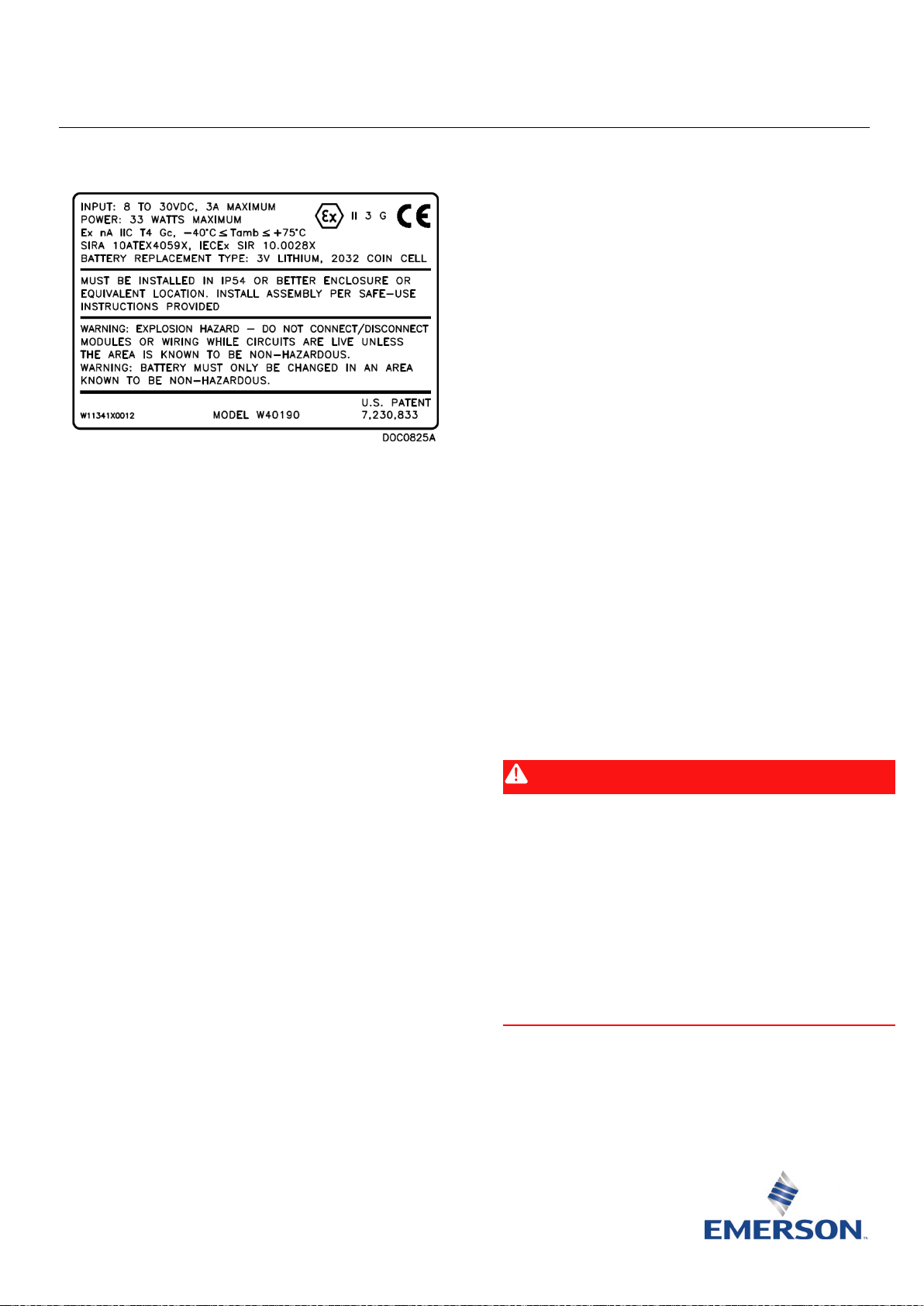
艾默生 FloBossTM 107 流量管理器
本设备的认证使用环境温度范围是 –40°C 至 +75°C,
不得在超出此温度范围的环境中使用。
设备的安装应当由经过适当培训的专业人员根据适
用的操作规范(通常是 IEC EN 60079-14)来执行。
本设备不需要装配或拆解。
关于安全性方面,没有必要检查运行是否正确。
无需用户进行调整。
应由经过适当培训的专业人员根据适用的操作
规范定期对设备进行检查,以确保设备保持良好状况。
本设备不可由用户修理。设备的修理应由制造商或其
图
1. FloBoss 107
此安全使用说明 (SUI) 文档应与 FloBoss 107
明手册
(手册编号 D301232X02)一起使用。有关安装和
故障排除过程的所有注意事项和说明,请参阅该手册。
流量管理器铭牌(图示为
流量管理器说
ATEX
版)
FloBoss 107 安全使用的特殊条件
与 LOI(D 型接口)端口连接的线缆应当使用规格合
适的螺丝以机械方式固定,以防止在使用过程中松开
或断开。
在使用以太网连接时,增强通信模块的 RJ45(以太网)
连接必须使用具有可靠固定夹片的咬合式接头,以防
止在使用过程中松开或断开。
增强通信模块上的 USB 接头不得使用,除非该区域确
认为无危险(非易燃)区域。
将 FB107 安装在合适的通过 ATEX 或 IECEx 认证的
IP54 或更高防护等级的机柜内。
设备使用环境的污染度不能超过 2 级(根据 EIC
60664-1 定义),也就是使用环境中不能存在导电性
污染物,并且应当将设备安装在室内或避光的地方。
本设备可在含有可燃气体的区域 2 中使用。
本设备可在含有可燃气体和蒸汽的环境中与器具组
IIC、IIB 或 IIA 一起使用,还可在温度等级 T1、T2、
T3 或 T4 环境中使用。
认可的代理商依照适用的操作规范来执行。
本设备不包含任何用户可自行更换的零部件。
在某些极端情况下,包含在本设备壳体内的非金属零
部件可能产生可点燃的静电电荷。因此,应只使用湿
布来清洁本设备。
如果设备有可能接触到侵蚀性物质(例如,可能腐蚀
金属的酸性液体或气体,或者是可能影响聚合材料的
溶剂),那么用户应负责采取适当的预防措施来防止
设备受到不利影响,从而确保能够维持适当的防护等
级。
符合性声明
Remote Automation Solutions 特此声明 FloBoss 107 产品
符合欧洲指令 2014/30/EU (EMC) 和 2014/34/EU (ATEX)
中适用的基本要求和其他相关规定。
危险
在危险区域安装组件时,请确保所选的所有安装组件都标
明了可以用于这些区域。仅当这些区域被确认为无危险时,
才可以执行安装和维护。在危险区域安装可能导致人员受
伤或财产损坏。
尝试进行任何类型的接线之前,务必关闭 FloBoss 的电源。
对通电设备进行接线可能会造成人员受伤或财产损坏。
为防止在装置内工作时损坏电路,请采取适当的静电放电
防护措施(例如佩戴接地腕带)。
安全使用说明 – 艾默生 FloBoss107 流量管理器
文档编号 D301594X412
2021 年 6 月
远程自动化解决方案
只能在已知不会产生危险的区域中打开盖子。
Page 27

安全使用说明 – 艾默生 FloBoss107 流量管理器
规格
电源
外部电源充电输入:
输入:
环境
工作环境温度:
储存温度:
工作湿度:
重量
审批
ATEX/IECEx
4X Ø4.8
][
0.19
134.4
5.29
][
]
6.22
[
158.0
][
5.00
127.0
][
15.5
0.61
][
9.1
0.36
196.1
7.72
[ ]
][
177.8
7.00
8.88
[ ]
225.6
[
8.47
215.1
]
0.24
6.1
[
]
7.00
177.8
[ ]
5.00
127.0
[ ]
165.1
6.50
[ ]
][
7.68
195.1
4X Ø4.8 [0.19]
文档编号 D301594X412
2021 年 6 月
8-30 V DC,极性反接保护。
8-30 V DC,最大 3A,最大 33 瓦。
–40 至 75°C。
-50 至 85°C。
5 至 95%,无冷凝。
0.76 千克(4 插槽主机组和单 CPU 模块)。
已通过以下标准的评估:
EN 60079-0 (2012/A11:2013)
EN 60079-15 (2010)
IEC 60079-0 (2011 Ed 6)
IEC 60079-15 (2010 Ed 4)
已通过 Sira 的 Model W40190 认证。
ATEX 证书 Sira 10ATEX4059X
IECEx 证书 IECEx SIR 10.0028X
危险场所使用产品标记:
Ex nA IIC T4 Gc,–40°C ≤ T
≤ +75℃
amb
图
2. FB107
主机组安装在适配板上。将其放置在机柜装配板
尺寸
上的合适位置,使用适配板插槽作为模板定位板
上的安装孔。适配板的尺寸信息请参见
8-32 UNC 螺丝锥在板上安装孔的位置进行钻孔攻
丝。将装有适配板的 FB107
放置在钻攻好的位置上,然后使用随附的四个 8-
32 UNC x 0.38 英寸长螺丝将其固定到装配板上。
拧紧螺钉。
图
3。使用
II 3 G。
进行安装、维护和故障排除时需要以下工具:
运行 Microsoft
Windows 10 及艾默生现场工具组态软件的个人电脑
(提供 ROCLINK™ 800 组态软件)。
十字螺丝刀。
平头螺丝刀。
1. 您收到包装在箱子中的 FB107 后,将其从包装箱中取
出。
2. FB107 以四种主要配置之一提供,具体取决于订购的
配置。将 FB107 安装在合适的通过 ATEX 或 IECEx 认
证的 IP54 或更高防护等级的机柜中,遵循以下指导
原则:
主机组。将其放置在机柜装配板上的合适位置,
使用
尺寸信息请参见
上安装孔的位置进行钻孔攻丝。将 FB107 放置在
2 www.Emerson.com/RemoteAutomation
钻攻好的位置上,然后使用随附的四个 8-32 UNC
x 1.00 英寸长螺丝将其固定到装配板上。以大约
1.1 至 1.4 牛米的转矩拧紧螺丝。
注: 如果替代使用公制螺丝,请使用大圆头螺丝
®
Windows® 7、Windows 8.1 或
FB107 作为模板定位板上的安装孔。FB107
图
以避免在拧紧时造成塑料外壳破裂。
2。使用 8-32 UNC 螺丝锥在板
图
3.
适配板尺寸
主机组和扩展机架。将主机组放置在机柜装配板
上,使用
FB107 作为模板定位板上的安装孔。主
机组和扩展支架的尺寸请参见
图
4。使用 8-32
UNC 螺丝锥在板上安装孔的位置进行钻孔攻丝。
将主机组放置在钻攻好的位置上,然后使用随附
的四个 8-32 UNC x 1.00 英寸长螺丝将其固定到装
配板上。不要完全拧紧。将扩展机架插入到主机
组中,保持好位置,然后标记出机架安装孔的位
置。小心拆下扩展机架,然后使用 8-32 UNC 螺丝
锥在板上安装孔的位置进行钻孔攻丝。将扩展机
架插入到主机组中,然后使用随附的 8-32 UNC x
1.00 英寸长螺丝将其固定到装配板上。以大约 1.1
至 1.4 牛米的转矩拧入八个固定螺丝。
注: 如果替代使用公制螺丝,请使用大圆头螺丝
以避免在拧紧时造成塑料外壳破裂。
Page 28
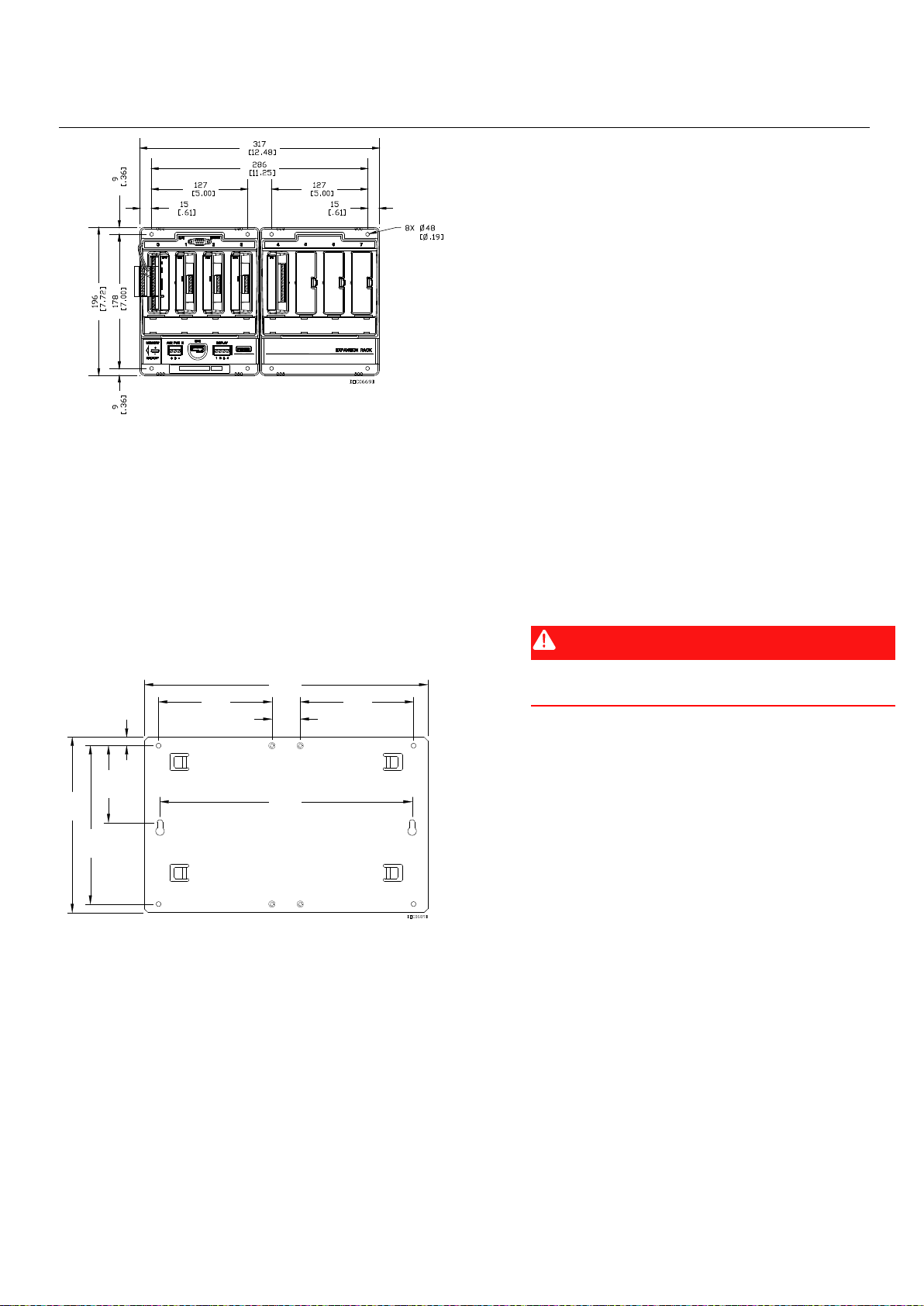
安全使用说明 – 艾默生 FloBoss107 流量管理器
31.8
1.25
[ ]
5.00
127.0
[ ]
127.0
5.00
[ ]
317.5
12.50
[ ]
11.12
[
282.5
]
3.40
86.4
[ ]
0.38
9.5
[
]
7.00
[
177.8
]
][
7.75
196.8
文档编号 D301594X412
2021 年 6 月
FB107 正确接地可减少电噪声对装置运行的影响,并
可防止雷电袭击。FB107 可为内置现场接线输入和输
出提供避雷保护。
所有接地的地面与接地棒或接地网之间的阻抗必须为
2.0 欧姆或以下(使用接地系统检测器检测)。FB107
壳体地线与接地棒或接地网之间的接地导体电阻不应
超过 1 欧姆。
如果管道与地面之间的阻抗大于 2 欧姆,则必须电气
隔离 FB107,并安装接地棒或接地网接地系统。
建议的 I/O 信号配线电缆为绝缘、屏蔽的双绞线。双
绞线和屏蔽最大限度减少由 EMI(电磁干扰)、RFI
(射频干扰)和瞬变导致的信号错误。
图
4. FB107
带扩展机架的主机组安装在适配板上。将其放置
在机柜装配板上的合适位置,使用
和扩展机架尺寸
FB107 组件作
为模板定位板上的安装孔。适配板的尺寸信息请
参见
图
5。使用 8-32 UNC 螺丝锥在板上安装孔的
位置进行钻孔攻丝。将 FB107 组件放置在钻攻好
的位置上,然后使用随附的四个 8-32 UNC x 1.00
英寸长螺丝将其固定到装配板上。以大约 1.1 至
1.4 牛米的转矩拧入四个固定螺丝。
注: 如果替代使用公制螺丝,请使用大圆头螺丝
以避免在拧紧时造成塑料外壳破裂。
6. 将 FB107 连接到电源、I/O 设备和通信设备。外部连
接(或现场端子)均位于端接板上。接线端子可接受
最高 16 AWG 规格的线。
FB107 接口使用压接型端子。输入电源端子 (IN+ /
IN–) 使用可拆卸接头并最多可接纳尺寸为 16 AWG 的
线。在所有情况下,剥开线缆的末端(最多 6 毫米),
将裸露端插入端子螺栓下方的接线夹中,然后以 0.25
牛米拧紧螺钉。
插入的线应尽量减少裸线外露部分,以防止短路。连
接时保持一定的松弛度,以防过紧。
危险
不要用过大的扭矩力来拧紧接头螺钉。
注:在打开电源之前,先检查输入电源的极性。
7. 接通 FB107 电源。
8. 在将 FB107 投入使用前对其进行组态。您可以使用在
个人计算机上运行的 ROCLINK 800 组态软件对设备进
行组态。通常是将计算机连接到 FB107 的 LOI 端口以
将组态数据传输到 FB107 中,也可以脱机设定组态,
稍后再将组态加载到 FB107 中。
图
5.
适配板尺寸
3. 对机柜中的 FB107 执行电气强度测试。测试方法为:
将 AUX PWR IN、DVS 和 DISPLAY 连接短路,并将适
配板或本地装置接地。使用下列电压之一:
500 V r.m.s (+5%, –0%),60 秒
700 V DC (+5%, –0%),60 秒
电流最大不超过 5 mA;确保不要出现断电或飞弧。
4. 找到机柜组件的合适位置。选择安装地点时,确保检
查所有间隙。留出足够的间隙进行接线和维修。密封
机柜上的所有孔洞,以维持 IP54 机柜防护等级。确
保配件的安装符合所有重量要求,并且确保安装符合
当地建筑法规。
5. 将 FB107 正确接地。
www.Emerson.com/RemoteAutomation 3
FB107 固件提供所有参数的默认值。如果默认值适合
您的应用,则请将它们保留原样。您可以使用
ROCLINK 800 调整参数值。请参阅 ROCLINK 800
软件用户手册(用于
FloBoss 107)(手册编号
组态
D301249X012)。
9. 校准例程支持 5 点校准,三个中间点可以按任意顺序
校准。首先校准低端或零点读数,然后校准高端或满
量程读数。如果需要,可再次校准三个中间点。诊断
模拟输入—逻辑电压 (E1)、电池电压 (E2) 和板/电池
温度 (E5)—无需校准。
如果安装了可选 I/O 端接点,则可使用 ROCLINK 800
校准模拟输入。
Page 29

安全使用说明 – 艾默生 FloBoss107 流量管理器
文档编号 D301594X412
2021 年 6 月
这些模拟输入的校准程序在 ROCLINK 800
户手册(用于
D301249X012)中说明。
10. 要排除 FB107 的故障,请确认问题是与组态还是硬件
相关。检查(使用 ROCLINK 800)组态以识别任何错
误设置。检查硬件有无损坏。检查端接板上的连接位
置有无错误。
如果 FB107 的问题可能与软件有关,则请通过热启动、
冷启动或是重置操作来对 FB107 进行重置。
注: 重置固件可能会将设备及其组态恢复为出厂时
如果您遇到的问题可能与硬件有关,请检查接线。如
果问题仍然存在,请联系您的当地销售处以获取返修
授权。
11. 要停用 FB107:
检查安全区。
断开装置的电源。
移除所有外部接线连接。
将 FB107 从其机柜中拆下。
FloBoss 107)(手册编号
设置。确保您已将所有组态和设置保存到计算
机或移动介质上。
组态软件用
12. 将 FB107 存放于合适的容器中以便运输。
4 www.Emerson.com/RemoteAutomation
Page 30

全球总部
北美及拉丁美洲:
有权随时修改或
欧洲:
中东/非洲:
亚太:
如需客户服务和技术支持,请访问
www.Emerson.com/SupportNet。
艾默生自动化解决方案
远程自动化解决方案
美国德克萨斯州休斯顿,邮编 77072
Rogerdale 路 6005 号。
电话 +1 281 879 2699
传真 +1 281 988 4445
www.Emerson.com/RemoteAutomation
安全使用说明 – 艾默生 FloBoss107 流量管理器
文档编号 D301594X412
2021 年 6 月
艾默生自动化解决方案
远程自动化解决方案
英国达德利布赖尔利山
达德利大道
滨水商业公园 8 单元,邮编 DY5 1LX
电话 +44 1384 487200
艾默生自动化解决方案
远程自动化解决方案
阿拉伯联合酋长国迪拜
杰贝阿里自由贸易区-南 2 号
艾默生 FZE
邮政信箱 17033
电话 +971 4 8118100
传真 +971 4 8865465
艾默生自动化解决方案
远程自动化解决方案
新加坡班丹湾 1 号
邮编:128461
电话 +65 6777 8211
传真 +65 6777 0947
© 2010–2021 艾默生自动化解决方案远程自动化解决方案业务部门。保留所有权利。
本刊物内容仅供参考。我们已尽最大努力确保准确性,本刊物不得视为对此处所述产品或服
务以及其使用或适用性的明示或暗示保证或担保。远程自动化解决方案 (RAS)
改进其产品的设计或规格,恕不另行通知。所有销售均受 RAS 的条款和条件的制约,这些条
款或条件在要求时可提供。RAS 概不承担正确选择、使用或维护任何产品的责任,该等责任
应由购买者和/或最终用户独自承担。
远程自动化解决方案
Page 31

Istruzioni per l'uso sicuro – Flow Manager FloBoss 107 Emerson
Flow Manager FloBoss™ 107 Emerson
L'apparecchio deve essere installato da personale
qualificato in conformità con il codice di condotta
applicabile (tipicamente IEC EN 60079-14).
L'apparecchio non richiede montaggio o smontaggio.
Per quanto riguarda la sicurezza, non è necessario
verificare il corretto funzionamento.
Non è necessaria alcuna regolazione da parte
dell'utente.
Al fine di garantire il mantenimento di condizioni di
funzionamento soddisfacenti, devono essere eseguiti
regolari controlli periodici dell'apparecchio da parte di
Figura 1. Targhetta dati del Flow Manager FloBoss 107
(versione ATEX illustrata)
Utilizzare queste istruzioni per l'uso sicuro (SUI, Safe Use
Instructions) con il Manuale di istruzioni del Flow Manager
FloBoss 107 (parte D301232X02). Per tutte le avvertenze e
le descrizioni delle procedure di installazione e la
risoluzione dei problemi, fare riferimento al manuale.
Condizioni speciali per l'uso sicuro del FloBoss
104
I collegamenti alla porta LOI (connettore di tipo D)
devono essere fissati meccanicamente in posizione
con collegamenti a vite adeguati, per prevenire
l'allentamento o la disconnessione durante l'uso.
Quando si utilizzano connessioni Ethernet, la
connessione RJ45 (Ethernet) del modulo di
comunicazione avanzato deve disporre di un
connettore di accoppiamento con una clip di chiusura
valida, per prevenire l'allentamento o la disconnessione
durante l'uso.
Il connettore USB sul modulo di comunicazione
avanzato non deve essere utilizzato, a meno che non
si trovi in un'area non pericolosa (non infiammabile).
Installare l'FB107 all'interno di un alloggiamento
approvato IP54, certificato ATEX o IECEx o migliore.
L'area in cui si utilizza l'apparecchio deve essere a un
grado minimo di inquinamento 2, come definito dalla
norma IEC 60664-1 (vale a dire, l'ambiente non deve
contenere inquinamento conduttivo e l'apparecchio
deve essere installato all'interno o in una posizione
protetta).
L'apparecchio può essere usato in un'area con gas
infiammabili di grado 2.
L'apparecchio può essere utilizzato in presenza di gas
e vapori infiammabili con gruppi di apparati IIC o IIB e
IIA e con classi di temperature T1 o T2 o T3 o T4.
L'apparecchio è certificato per l'utilizzo in ambienti
con temperature comprese tra -40 °C a +75 °C e non
deve essere usato fuori di tale intervallo.
personale appositamente addestrato, in conformità
con il codice di condotta applicabile.
L'apparecchio non deve essere riparato dall'utente.
La riparazione dell'apparecchio deve essere eseguita
dal produttore o dai suoi agenti autorizzati, in
conformità con il codice di condotta applicabile.
L'apparecchio non contiene altre parti sostituibili dal
cliente.
In presenza di circostanze estreme, i componenti non
metallici dell'alloggiamento di questo apparecchio
possono generare un livello di carica elettrostatica
in grado di causare un'ignizione. Ne consegue che
l'apparecchio può essere pulito esclusivamente con
un panno umido.
Se è possibile che l’apparecchio venga a contatto
con sostanze aggressive (come liquidi o gas acidi che
potrebbero attaccare i metalli o solventi che
potrebbero influire sulla composizione dei materiali
polimerici), è responsabilità dell’utente adottare le
necessarie precauzioni per evitare effetti indesiderati
e la compromissione del tipo di protezione.
Dichiarazione di conformità
Di seguito è riportata la dichiarazione di Remote
Automation Solutions relativa alla conformità di FloBoss
107 ai requisiti essenziali e alle altre disposizioni pertinenti
della Direttiva Europea 2014/30/EU (EMC) e 2014/34/EU
(ATEX).
PERICOLO
In caso di installazione delle unità in un'area pericolosa,
assicurarsi che tutti i componenti di installazione
selezionati riportino l'etichetta per l'uso in tali aree.
L'installazione e la manutenzione devono essere eseguite
solo se si è certi della non pericolosità dell'area.
L'installazione in aree pericolose può causare lesioni
personali o danni alle proprietà.
Spegnere sempre l'alimentazione del FloBoss prima di
qualsiasi tipo di cablaggio. Il cablaggio di un apparecchio
alimentato può causare lesioni personali o danni alle
proprietà.
Codice D301594X412
Giugno 2021
Remote Automation Solutions
Page 32

Istruzioni per l'uso sicuro – Flow Manager FloBoss 107 Emerson
Specifiche
ALIMENTAZIONE
Ingresso di carica alimentazione esterna:
Ingresso:
SPECIFICHE AMBIENTALI
Temperatura ambiente di esercizio:
Temperatura di stoccaggio:
Umidità di esercizio:
PESO
CERTIFICAZIONI
ATEX/IECEx
4X Ø4.8
]
[
0.19
134.4
5.29
]
[
]
6.22
[
158.0
][
5.00
127.0
]
[
15.5
0.61
][
9.1
0.36
196.1
7.72
[ ]
][
177.8
7.00
8.88
[ ]
225.6
[
8.47
215.1
]
0.24
6.1
[ ]
7.00
177.8
[ ]
5.00
127.0
[ ]
165.1
6.50
[ ]
][
7.68
195.1
Codice D301594X412
Giugno 2021
Per evitare danni al circuito quando si lavora sull'unità,
adottare le precauzioni necessarie contro le scariche
elettrostatiche, indossare per esempio un bracciale con
messa a terra.
Non aprire i coperchi, a meno che l'area non sia nota per
essere non pericolosa.
8-30 V c.c.,
protezione contro l'inversione della polarità.
8-30 V cc, 3 A max, 33 W max.
da -40 a 75 °C.
da -50 a 85 °C.
da 5 a 95%, senza condensa.
0,76 kg (unità principale a 4 slot e un modulo CPU).
Solo unità principale. Posizionare come desiderato
sulla piastra di montaggio dell'alloggiamento e
individuare i fori di montaggio sulla piastra usando
l'FB107 come una matrice. Per le dimensioni
dell'FB107, vedere la Figura 2. Forare e maschiare fori
di montaggio nella piastra con un maschiatore 8-32
UNC. Posizionare l'FB107 sulle posizioni maschiate e
fissarlo alla piastra con le quattro viti
8-32 UNC x 1,00" fornite. Serrare le viti a circa
1,1 - 1,4 N-m.
Nota: se si utilizzano viti con dimensioni metriche,
utilizzare viti a testa tonda larga per impedire la
rottura dell'alloggiamento in plastica durante il
serraggio.
Valutato secondo i seguenti standard:
EN 60079-0 (2012/A11:2013)
EN 60079-15 (2010)
IEC 60079-0 (2011 Ed 6)
IEC 60079-15 (2010 Ed 4)
Certificato da Sira come Modello W40190.
ATEX Cert Sira 10ATEX4059X
IECEx Cert IECEx SIR 10.0028X
Marcature del prodotto per le aree pericolose:
Ex nA IIC T4 Gc, –40 °C ≤ T
II 3 G.
Sono necessari i seguenti strumenti per l'installazione, la
manutenzione e la risoluzione dei problemi:
amb
Personal computer con sistema operativo Microsoft
Windows
configurazione Field Tools Emerson (con software di
®
7, Windows 8.1 o Windows 10 e software di
configurazione ROCLINK™ 800).
Cacciavite Phillips (punta a croce).
Cacciavite a testa piatta.
1. FB107 viene fornito in una scatola. Estrarre
l'apparecchio dalla scatola.
2. L'FB107 viene fornito in una di quattro configurazioni
principali, secondo quanto ordinato. Installare l'FB107
in un alloggiamento omologato ATEX o IECEx
conforme allo standard IP54 o migliore attenendosi
alle seguenti istruzioni:
2 www.Emerson.com/RemoteAutomation
≤ +75 °C
Figura 2. Dimensioni dell'FB107
Unità principale montata su pannello adattatore.
Posizionare come desiderato sulla piastra di
montaggio dell'alloggiamento e individuare i fori
di montaggio sulla piastra usando le scanalature
del pannello adattatore come una matrice. Per le
dimensioni del pannello adattatore, vedere la Figura 3.
Forare e maschiare fori di montaggio nella piastra con
un maschiatore 8-32 UNC. Posizionare l'FB107 con il
pannello adattatore sulle posizioni maschiate
e fissarlo alla piastra con le quattro viti
8-32 UNC x 0,38" fornite. Serrare le viti fino in fondo.
®
Figura 3. Dimensioni del pannello
Page 33

Istruzioni per l'uso sicuro – Flow Manager FloBoss 107 Emerson
31.8
1.25
[ ]
5.00
127.0
[ ]
127.0
5.00
[ ]
317.5
12.50
[ ]
11.12
[
282.5
]
3.40
86.4
[ ]
0.38
9.5
[
]
7.00
[
177.8
]
][
7.75
196.8
Codice D301594X412
Giugno 2021
Unità principale e rack di espansione. Posizionare
l'unità principale sulla piastra di montaggio
dell'alloggiamento e individuare i fori di
montaggio sulla piastra usando l'FB107 come una
matrice. Per le dimensioni dell'unità principale
con rack di espansione, vedere la Figura 4. Forare e
maschiare fori di montaggio nella piastra con un
maschiatore 8-32 UNC. Posizionare l'unità
principale sulle posizioni maschiate e fissarla alla
piastra con le quattro viti 8-32 UNC x 1,00"
fornite. Non serrare completamente. Installare il
rack di espansione nell'unità principale e,
tenendolo in posizione, contrassegnare le
posizioni dei fori di montaggio del rack.
Rimuovere con cautela il rack di espansione,
quindi forare e maschiare i fori di montaggio nella
piastra con un maschiatore 8-32 UNC. Installare il
rack di espansione nell'unità principale e fissarlo
alla piastra con le quattro viti 8-32 UNC x 1,00"
fornite. Serrare le otto viti di montaggio a circa
1,1 - 1,4 N-m.
Nota: se si utilizzano viti con dimensioni
metriche, utilizzare viti a testa tonda larga
per impedire la rottura dell'alloggiamento
in plastica durante il serraggio.
rottura dell'alloggiamento in plastica durante il
serraggio.
Figura 5. Dimensioni del pannello
3. Effettuare un test di rigidità elettrica sull'FB107 nel
gruppo alloggiamento. Effettuare il test
cortocircuitando i collegamenti AUX PWR IN, DualVariable (DVS) e DISPLAY e il pannello adattatore o
collegandoli alla terra locale dell'impianto. Utilizzare
una delle tensioni indicate di seguito:
500 V r.m.s (+5%, –0%) per 60 secondi
700 V c.c. (+5%, –0%) per 60 secondi
Non superare una corrente massima di 5 mA;
accertarsi che non si verifichino scariche.
4. Trovare una posizione adatta per il gruppo
dell'alloggiamento. Quando si sceglie un luogo di
installazione, accertarsi di controllare le distanze
specificate. Lasciare uno spazio adeguato per il
cablaggio e la manutenzione. Sigillare i fori praticati
nell'alloggiamento per mantenere lo standard IP54
dell'alloggiamento. Verificare che il montaggio del
gruppo soddisfi tutti i requisiti di peso e che
l'installazione sia conforme alle norme in vigore.
Figura 4. Dimensioni dell'FB107 e del rack di espansione
Unità principale con rack di espansione montata su
pannello adattatore. Posizionare come desiderato
sulla piastra di montaggio dell'alloggiamento e
individuare i fori di montaggio sulla piastra usando
il gruppo dell'FB107 come una matrice. Per le
dimensioni del pannello adattatore, vedere la Figura 5.
Forare e maschiare fori di montaggio nella piastra con
un maschiatore 8-32 UNC. Posizionare il gruppo
dell'FB107 sulle posizioni maschiate e fissarlo alla
piastra con le quattro viti 8-32 UNC x 1,00" fornite.
Serrare le quattro viti di montaggio a circa 1,1 - 1,4 Nm.
Nota: se si utilizzano viti con dimensioni metriche,
www.Emerson.com/RemoteAutomation 3
utilizzare viti a testa tonda larga per impedire la
5. Collegare a terra in modo adeguato l'FB107.
Il corretto collegamento alla terra dell'FB107 aiuta a
ridurre gli effetti del rumore elettrico sul
funzionamento dell'unità e a proteggerla dai fulmini.
L'FB107 fornisce protezione dai fulmini per gli ingressi
e le uscite incorporate del cablaggio sul campo.
Tutti i collegamenti di messa a terra devono essere
dotati di un'impedenza della massa o della griglia di
2,0 ohm o meno, come misurato con un apposito
tester. Il conduttore di messa a terra deve avere una
resistenza di 1 ohm o meno tra la messa a terra della
custodia dell'FB107 e il dispersore o la griglia di messa
a terra.
Se l'impedenza dalla conduttura alla terra è maggiore
di 2 ohm, isolare elettricamente l'FB107 e installare
una sistema di massa o griglia.
Page 34

Istruzioni per l'uso sicuro – Flow Manager FloBoss 107 Emerson
Codice D301594X412
Giugno 2021
Il cavo consigliato per il cablaggio di segnale I/O è un
doppino intrecciato schermato e isolato. Il doppino
intrecciato e la schermatura riducono al minimo gli
errori di segnale causati dall'interferenza
elettromagnetica (EMI), dall'interferenza in
radiofrequenza (RFI) e dai transitori.
6. Collegare l'FB107 all'alimentazione, ai dispositivi di I/O
e ai dispositivi di comunicazione. I collegamenti
esterni (o terminali sul campo) si trovano tutti sulla
scheda di terminazione. La morsettiera accetta cavi
fino a 16 AWG.
I connettori dell'FB107 utilizzano terminali a
compressione. La terminazione dell'alimentazione in
ingresso (IN+ / IN-) utilizza un connettore rimovibile
ed è in grado di ospitare cavi fino a 16 AWG. In tutti i
casi, effettuare i collegamenti spellando l'estremità
del filo (6 mm al massimo), inserendo l'estremità
spellata nel morsetto sotto la vite della terminazione,
quindi avvitare la vite a 0,25 N-m.
I fili inseriti devono avere il minimo possibile di filo
spellato esposto per evitare cortocircuiti. Lasciare un
certo gioco quando si effettuano i collegamenti,
per evitare sollecitazioni eccessive.
PERICOLO
non serrare eccessivamente le viti del connettore.
7. Applicare l'alimentazione all'FB107.
8. Configurare l'FB107 prima di metterlo in servizio. Il
dispositivo si configura utilizzando il software di
configurazione ROCLINK 800, eseguito su un personal
computer. Normalmente si collega il PC alla porta LOI
dell'FB107 per trasferire i dati di configurazione
nell'FB107, sebbene sia anche possibile sviluppare
configurazioni offline e caricarle nell'FB107 in un
secondo momento.
Il firmware dell'FB107 fornisce valori predefiniti per
tutti i parametri. Se i valori predefiniti sono accettabili
per la propria applicazione, lasciarli inalterati. Per
regolare i valori dei parametri si utilizza ROCLINK 800.
Fare riferimento al Manuale dell'utente del software di
configurazione ROCLINK 800 (per FloBoss 107) (parte
D301249X012).
9. Le routine di taratura supportano la taratura a 5 punti,
con tre punti centrali tarati in qualsiasi ordine.
Innanzitutto viene tarata la lettura minima o di zero,
seguita dalla lettura massima o di fondo scala.
Successivamente, è possibile tarare i tre punti centrali.
Non è prevista la taratura degli ingressi analogici di
diagnostica, ossia tensione logica (E1), tensione della
batteria (E2) e temperatura della scheda/batteria (E5).
Con i punti di terminazione I/O opzionali installati,
tarare l'ingresso analogico utilizzando ROCLINK 800.
La procedura di taratura per questi ingressi è descritta
nel manuale dell'utente del software di configurazione
ROCLINK 800 (per FloBoss 107) (parte D301249X012).
10. Per risolvere eventuali problemi con l'FB107,
determinare se il problema è relativo alla
configurazione o all'hardware. Controllare la
configurazione (utilizzando ROCLINK 800) per
identificare eventuali impostazioni non corrette.
Verificare l'eventuale presenza di danni sull'hardware.
Controllare le schede di terminazione per eventuali
errori di posizione delle connessioni.
Se i problemi dell'FB107 sembrano relativi al software,
provare a ripristinare l'FB107 con un avvio a caldo, un
avvio a freddo o un ripristino.
Nota: il ripristino del firmware può ripristinare il
dispositivo e la relativa configurazione alle
impostazioni di fabbrica. Accertarsi di avere
salvato le impostazioni di configurazione nel
proprio PC o su un supporto rimovibile.
Se si verificano problemi che sembrano correlati
all'hardware, verificare il cablaggio. Se il problema
persiste, contattare l'ufficio vendite locale per
l'autorizzazione alla restituzione.
11. Per interrompere il funzionamento dell'FB107:
Verificare la sicurezza dell'area.
Scollegare l’alimentazione dall'unità.
Rimuovere tutti i cavi di collegamento esterni.
Estrarre l'FB107 dall'alloggiamento.
12. Collocare l'FB107 in un apposito contenitore per il
trasporto o la spedizione.
4 www.Emerson.com/RemoteAutomation
Page 35

Istruzioni per l'uso sicuro – Flow Manager FloBoss 107 Emerson
Sedi centrali
Nord America e America Latina:
Tel. +1 281 879 2699 | Fax +1 281 988 4445
applicabilità. Remote Automation Solutions (RAS) si riserva il diritto di modificare o migliorare il
esclusivamente dell'acquirente.
Europa
Medio Oriente/Africa:
Asia-Pacifico:
Tel. +65 6777 8211| Fax +65 6777 0947
Codice D301594X412
Giugno 2021
Per il servizio clienti e il supporto tecnico,
visitare il sito www.Emerson.com/SupportNet.
Emerson Automation Soltuions
Remote Automation Solutions
6005 Rogerdale Road
Houston, TX 77072 U.S.A.
www.Emerson.com/RemoteAutomation
:
Emerson Automation Solutions
Remote Automation Solutions
Unit 1, Waterfront Business Park
Dudley Road, Brierley Hill
Dudley DY5 1LX UK
Tel. +44 1384 487200
Emerson Automation Solutions
Remote Automation Solutions
Emerson FZE
P.O. Box 17033
Jebel Ali Free Zone – South 2
Dubai U.A.E.
Tel. +971 4 8118100 | Fax +971 4 8865465
Emerson Automation Solutions
Remote Automation Solutions
1 Pandan Crescent
Singapore 128461
© 2010 – 2021 Remote Automation Solutions, una business unit di Emerson Automation
Solutions. Tutti i diritti riservati.
Questo documento ha fini esclusivamente informativi. Sebbene ogni sforzo sia stato profuso
per garantire la correttezza delle informazioni, queste non vanno interpretate come garanzie,
esplicite o implicite, da riferirsi ai prodotti o ai servizi ivi descritti, né al loro impiego o alla loro
design o le specifiche di tali prodotti in qualsiasi momento senza preavviso. Tutte le vendite
sono soggette ai termini e condizioni di RAS, disponibili su richiesta. RAS non si assume la
responsabilità per la selezione, l'uso e la manutenzione corretti di qualsiasi prodotto, che è
Remote Automation Solutions
Page 36
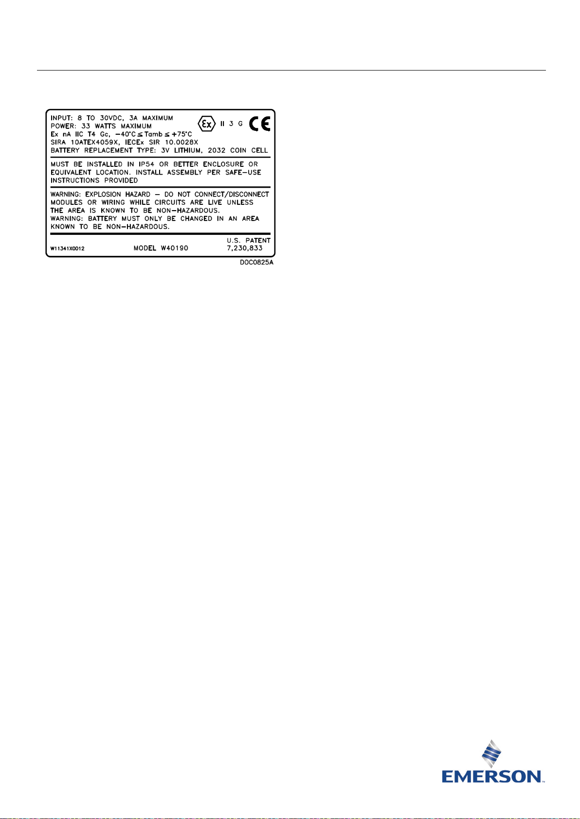
Instructies voor veilig gebruik – Emerson FloBoss 107 Flow Manager
Emerson FloBoss™ 107 Flow Manager
De apparatuur kan gebruikt worden met
brandgevaarlijke gassen en dampen met
apparatuurgroep IIC, IIB of IIA en temperatuurklasse
T1, T2, T3 of T4.
De apparatuur is gecertificeerd voor gebruik bij
omgevingstemperaturen van -40 °C tot +75 °C en
mag buiten dit bereik niet worden gebruikt.
De installatie van deze apparatuur dient te worden
uitgevoerd door personeel met een gepaste
opleiding, in overeenstemming met de toepasselijke
regelgeving (met name IEC EN 60079-14).
Monteren of demonteren van deze apparatuur is niet
Afbeelding 1. Naamplaatje FloBoss 107 Flow Manager
(ATEX-versie afgebeeld)
Gebruik dit document met instructies voor veilig gebruik
samen met de Instructiehandleiding voor de FloBoss 107
Flow Manager (onderdeel D301232X02). Alle
aandachtspunten en omschrijvingen met betrekking tot
de installatie en het verhelpen van storingen vindt u in
deze handleiding.
Speciale voorwaarden voor veilig gebruik van
de FloBoss 103
Aansluitingen op de LOI-poort (D-type connector)
moeten mechanisch worden bevestigd met de passende
schroefverbindingen zodat losraken of loskoppeling
tijdens het gebruik wordt voorkomen.
Bij gebruik van ethernetverbindingen moet de RJ45
(Ethernet)-aansluiting op de Enhanced
Communications-module voorzien zijn van een
contrastekker met een degelijke veiligheidsklem
zodat losraken of loskoppeling tijdens het gebruik
wordt voorkomen.
De USB-connector op de Enhanced Communications-
module mag alleen worden gebruikt indien vaststaat
dat de ruimte ongevaarlijk (niet brandgevaarlijk) is.
Installeer de FB107 in een gepaste behuizing met
ATEX- of IECEx-goedkeuring en beschermingsgraad
van ten minste IP54.
De locatie waar de apparatuur wordt gebruikt moet
conform IEC 60664-1 minstens Contaminatiegraad 2
hebben (dat wil zeggen dat de omgeving geen
conductieve contaminatie mag bevatten en dat
apparatuur binnen of op een beschutte locatie dient
te worden geïnstalleerd).
De apparatuur kan in zone 2 met brandbare gassen
gebruikt worden.
vereist.
De juiste werking hoeft met betrekking tot veiligheid
niet te worden gecontroleerd.
Aanpassing door de gebruiker is niet vereist.
Regelmatige periodieke inspectie van deze apparatuur
dient te worden uitgevoerd door personeel met een
gepaste opleiding, in overeenstemming met de
toepasselijke regelgeving, om te verzekeren dat de
apparatuur in goede staat verkeert.
Het is niet de bedoeling dat de gebruiker de
apparatuur repareert. Reparatie van deze apparatuur
dient te worden uitgevoerd door de fabrikant of diens
erkende vertegenwoordigers in overeenstemming
met de van toepassing zijnde regelgeving.
De apparatuur bevat geen onderdelen die de klant
kan vervangen.
Onder bepaalde extreme omstandigheden kunnen de
niet-metallische onderdelen in de behuizing van deze
apparatuur een zodanig sterke elektrostatische lading
afgeven dat deze ontsteking kan veroorzaken.
Daarom dient de apparatuur uitsluitend met een
vochtige doek te worden gereinigd.
Als er een gerede kans bestaat dat de apparatuur in
aanraking komt met agressieve stoffen (zoals zuren en
zure gassen die metaal aantasten of oplosmiddelen die
polymeren kunnen aantasten) dan is de gebruiker
verantwoordelijk voor het nemen van gepaste
voorzorgsmaatregelen zodat de apparatuur niet nadelig
wordt beïnvloed en wordt verzekerd dat er geen inbreuk
wordt gemaakt op de bescherming die volgens het
beschermingstype wordt geboden.
Conformiteitsverklaring
Remote Automation Solutions verklaart bij deze dat het
product FloBoss 107 voldoet aan de essentiële eisen en
overige van toepassing zijnde relevante bepalingen van de
Europese richtlijnen 2014/30/EU (EMC) en 2014/34/EU
(ATEX).
Onderdeelnr. D301594X412
Juni 2021
Remote Automation Solutions
Page 37
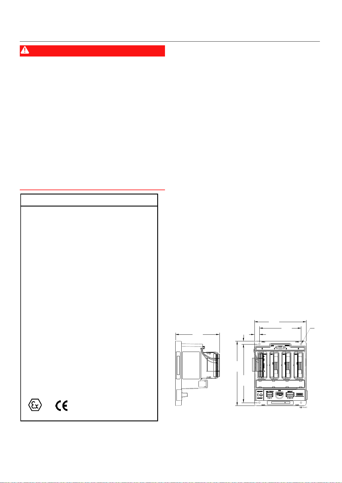
Instructies voor veilig gebruik – Emerson FloBoss 107 Flow Manager
Specificaties
VOEDING
Externe voedingsingang:
Ingang:
OMGEVING
Bedrijfstemperatuur:
Opslagtemperatuur:
Vochtigheidsgraad bedrijf:
GEWICHT
GOEDKEURINGEN
ATEX/IECEx
4X Ø4.8
][
0.19
134.4
5.29
][
]
6.22
[
158.0
][
5.00
127.0
][
15.5
0.61
][
9.1
0.36
196.1
7.72
[ ]
][
177.8
7.00
Onderdeelnr. D301594X412
Juni 2021
GEVAAR
Zorg als het apparaat in een gevaarlijke omgeving wordt
geïnstalleerd dat alle bij de installatie gebruikte
componenten geschikt zijn voor gebruik in een dergelijke
omgeving. Installatie en onderhoud mogen alleen
plaatsvinden als de omgeving daarvoor geen gevaar
oplevert. Installatie in een gevaarlijke omgeving kan leiden
tot persoonlijk letsel of materiële schade.
Schakel altijd eerst de stroom van de FloBoss uit voor u
werkzaamheden aan de bekabeling uitvoert. Het
bekabelen van ingeschakelde apparatuur kan tot
lichamelijk letsel of schade aan het apparaat leiden.
Neem bij werkzaamheden binnen in het apparaat
afdoende maatregelen om schade aan de schakelingen
door elektrostatische ontladingen te voorkomen,
bijvoorbeeld door een geaarde polsband te dragen.
Open panelen slechts dan als zeker is dat de omgeving
ongevaarlijk is.
omgekeerde polariteit.
8–30 V d.c., 3 A max, 33 W max.
condenserend.
0,76 kg (hoofdapparaat met 4 sleuven en een CPUmodule).
Beoordeeld volgens de onderstaande normen:
EN 60079-0 (2012/A11:2013)
EN 60079-15 (2010)
IEC 60079-0 (2011 Ed 6)
IEC 60079-15 (2010 Ed 4)
Gecertificeerd door Sira als model W40190.
ATEX-cert Sira 10ATEX4059X
IECEx-cert IECEx SIR 10.0028X
Productmarkering voor gevaarlijke locaties:
Ex nA IIC T4 Gc, –40 °C ≤ T
II 3 G.
8–30 V dc, beschermd tegen
–40 tot 75 °C.
–50 tot 85 °C.
amb
5 tot 95%, niet-
≤ +75 °C
Voor het installeren, uitvoeren van onderhoud en
verhelpen van storingen aan het apparaat zijn de volgende
gereedschappen vereist:
Pc met Microsoft
®
Windows® 7, Windows 8.1 of
Windows 10 en Emerson Field Toolsconfiguratiesoftware (met ROCLINK™ 800configuratiesoftware).
Kruiskopschroevendraaier.
Bladschroevendraaier.
1. De FB107 wordt geleverd in een doos. Haal het
apparaat uit de doos.
2. De FB107 wordt geleverd in een van vier
hoofdconfiguraties, afhankelijk van wat is besteld.
Installeer de FB107 in een gepaste behuizing met
ATEX- of IECEx-goedkeuring en beschermingsgraad
van ten minste IP54 aan de hand van de onderstaande
richtlijnen:
Alleen hoofdapparaat. Plaats het apparaat in de
gewenste stand op de montageplaat voor de
behuizing en kies de plaats voor de montagegaten
in de plaat met gebruikmaking van de FB107 als
mal. Zie Afbeelding 2 voor de afmetingen van de
FB107. Boor met een 8-32 UNC schroefdraadboor
de montagegaten aan en tap de schroefdraad in de
plaat. Plaats de FB107 op de schroefgaten en
bevestig hem op de plaat met de vier
meegeleverde 8-32 UNC x 1,00 inch lange
schroeven.
Draai de schroeven aan tot circa 1,1 tot
1,4 Nm.
NB Indien er in plaats van de meegeleverde
schroeven metrische schroeven worden
gebruikt, moeten dit schroeven met een kop
met vlakke onderzijde zijn om te voorkomen
dat de plastic behuizing scheurt tijdens het
aanhalen.
Afbeelding 2. Afmetingen van de FB107
Hoofdapparaat gemonteerd op adapterpaneel.
Plaats het apparaat in de gewenste stand op de
2 www.Emerson.com/RemoteAutomation
montageplaat voor de behuizing en kies de plaats
voor de montagegaten in de plaat met
Page 38
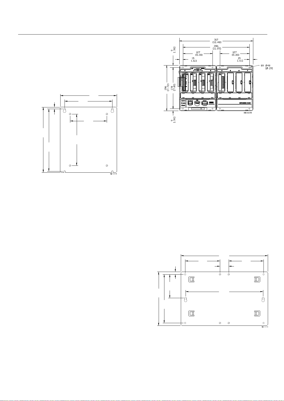
Instructies voor veilig gebruik – Emerson FloBoss 107 Flow Manager
8.88
[ ]
225.6
[
8.47
215.1
]
0.24
6.1
[ ]
7.00
177.8
[ ]
5.00
127.0
[ ]
165.1
6.50
[ ]
][
7.68
195.1
31.8
1.25
[ ]
5.00
127.0
[ ]
127.0
5.00
[ ]
317.5
12.50
[ ]
11.12
[
282.5
]
3.40
86.4
[ ]
0.38
9.5
[
]
7.00
[
177.8
]
][
7.75
196.8
gebruikmaking van de sleuven in het adapterpaneel
als mal. Zie Afbeelding 3 voor de afmetingen van het
adapterpaneel. Boor met een 8-32 UNC
schroefdraadboor de montagegaten aan en tap de
schroefdraad in de plaat. Plaats de FB107 met
adapterpaneel op de schroefgaten en bevestig hem
op de plaat met de vier meegeleverde 8-32 UNC x
0,38 inch lange schroeven. Draai de schroeven goed
aan.
Afbeelding 3. Afmetingen van het paneel
Hoofdapparaat en expansierek. Plaats het apparaat
op de montageplaat voor de behuizing en kies de
plaats voor de montagegaten in de plaat met
gebruikmaking van de FB107 als mal. Zie
Afbeelding 4 voor de afmetingen van het
hoofdapparaat met expansierek. Boor met een 832 UNC schroefdraadboor de montagegaten aan
en tap de schroefdraad in de plaat. Plaats het
hoofdapparaat op de schroefgaten en bevestig het
op de plaat met de vier meegeleverde
8-32 UNC x 1.00 inch lange schroeven. Niet
helemaal aanhalen. Steek het expansierek in het
hoofdapparaat, houd het daar op zijn plaats en
markeer de locaties voor de rekmontagegaten.
Verwijder het expansierek voorzichtig en boor en
tap de montagegaten vervolgens in de plaat met
een 8-32 UNC schroefdraadboor. Steek het
expansierek in het hoofdapparaat en bevestig het
op de plaat met de meegeleverde 8-32 UNC x 1.00
inch lange schroeven.
montageschroeven aan tot circa 1,1 tot 1,4 Nm.
Draai de acht
Onderdeelnr. D301594X412
Juni 2021
Afbeelding 4. Afmetingen van de FB107 en het expansierek
Hoofdapparaat met expansierek gemonteerd op
adapterpaneel. Plaats het geheel in de gewenste
stand op de montageplaat voor de behuizing en
kies de plaats voor de montagegaten in de plaat
met gebruikmaking van de FB107-constructie als
mal. Zie Afbeelding 5 voor de afmetingen van het
adapterpaneel. Boor met een 8-32 UNC
schroefdraadboor de montagegaten aan en tap de
schroefdraad in de plaat. Plaats de FB107constructie op de schroefgaten en bevestig hem
op de plaat met de vier meegeleverde 8-32 UNC x
1.00 inch lange schroeven.
Draai de vier
montageschroeven aan tot circa 1,1 tot 1,4 Nm.
NB Indien er in plaats van de meegeleverde
schroeven metrische schroeven worden
gebruikt, moeten dit schroeven met een kop
met vlakke onderzijde zijn om te voorkomen
dat de plastic behuizing scheurt tijdens het
aanhalen.
NB Indien er in plaats van de meegeleverde
schroeven metrische schroeven worden
gebruikt, moeten dit schroeven met een kop
www.Emerson.com/RemoteAutomation 3
met vlakke onderzijde zijn om te voorkomen
dat de plastic behuizing scheurt tijdens het
aanhalen.
Afbeelding 5. Afmetingen van het paneel
3. Voer een elektrische sterktetest uit op de FB107 in de
behuizing. Voer de test uit door het kortsluiten van de
AUX PWR IN-, DVS- en DISPLAY-aansluitingen en het
adapterpaneel of een plaatselijk aardverbinding in de
fabriek.
Gebruik een van de volgende spanningen:
500 V r.m.s (+5%, –0%) voor 60 seconden
Page 39

Instructies voor veilig gebruik – Emerson FloBoss 107 Flow Manager
Onderdeelnr. D301594X412
Juni 2021
700 V dc (+5%, –0%) voor 60 seconden
Overschrijd nooit een maximale stroomsterkte van 5 mA;
zorg dat er geen doorbraak of overslag is.
4. Kies een geschikte plaats voor de volledige behuizing.
Controleer bij de keuze van de installatieplek alle vrije
ruimten. Zorg voor voldoende ruimte voor de
bekabeling en het uitvoeren van onderhoud. Dicht alle
gaten in de behuizing af om de
beschermingsclassificatie IP54 te behouden. Zorg dat
de bevestiging van de behuizing voldoet aan alle
vereisten w.b. gewicht en dat de installatie voldoet
aan de plaatselijke bouwvoorschriften.
5. Zorg voor goede aarding van de FB107.
Door een correcte aarding van de FB107 worden de
effecten van elektrische stoorsignalen gereduceerd en
wordt het apparaat beschermd tegen blikseminslag.
De FB107 beschikt over bescherming tegen
blikseminslag voor geïntegreerde
veldbedradingsingangen en -uitgangen.
Alle aardvoorzieningen moeten een staaf- of
roosterimpedantie van niet meer dan 2,0 ohm hebben,
gemeten met een aardtester. De aardingsgeleider moet
een weerstand hebben van ten hoogste 1 ohm tussen
het aardpunt op de FB107-behuizing en de
aardingsstaaf of het -rooster.
Als de impedantie tussen de leiding en aarde groter is
dan 2 ohm, moet de FB107 elektrisch geïsoleerd
worden en moet een aardingsstaaf of
aardingsroostersysteem worden geïnstalleerd.
Voor de I/O-signaalbedrading wordt een geïsoleerde,
afgeschermde, getwiste, tweeaderige kabel
aanbevolen. De getwiste twee aders en de
afscherming beperken door elektromagnetische
storingen, radiofrequentiestoringen en
overgangsstromen veroorzaakte foutsignalen tot een
minimum.
GEVAAR
De verbindingsschroeven niet te strak aandraaien.
NB: Controleer of de polen correct zijn aangesloten
vóór de stroom wordt ingeschakeld.
7. Schakel de FB107 in.
8. Configureer de FB107 voordat u deze in bedrijf stelt. U
kunt het apparaat configureren met ROCLINK 800configuratiesoftware op een pc. Normaliter sluit u de
pc aan op de LOI-poort van de FB107 om
configuratiegegevens over te zetten op de FB107,
hoewel u ook offline configuraties kunt ontwikkelen
om ze later op de FB107 te zetten.
De firmware van de FB107 bevat standaardwaarden
voor alle parameters. Als de standaardinstellingen
aanvaardbaar zijn voor uw toepassing, laat u ze
ongewijzigd. U gebruikt ROCLINK 800 om de
parameterwaarden te wijzigen. Zie de
Gebruiksaanwijzing voor ROCLINK 800configuratiesoftware (voor FloBoss 107) (onderdeel
D301249X012).
9. Bij de kalibratieroutine kan 5-puntskalibratie worden
gebruikt, waarbij de drie middelste punten in
willekeurige volgorde kunnen worden gekalibreerd.
De lage of nullezing wordt eerst gekalibreerd, gevolgd
door de hoge of volledigeschaallezing. De drie
tussenliggende punten kunnen daarna desgewenst
worden gekalibreerd. De analoge ingangen voor
diagnose - logisch voltage (E1), accuvoltage (E2) en
printplaat/accutemperatuur (E5) - zijn niet ontworpen
om te worden gekalibreerd.
Als de optionele I/O-afsluitpunten zijn geïnstalleerd,
kalibreert u de analoge ingang met de ROCLINK 800software.
6. Sluit de FB107 aan op de voeding, de I/O-
instrumenten en de communicatieapparatuur. Alle
externe aansluitingen (of veldklemmen) bevinden zich
op het klemmenbord. Op het klemmenbord kan
bekabeling tot maximaal 16 AWG worden gebruikt.
De connectors van de FB107 zijn drukklemmen. De klem
voor de ingangsspanning (CHG+ / CHG–) heeft een
verwijderbare connector en hiervoor kan bekabeling tot
maximaal 16 AWG worden gebruikt. In alle gevallen
moeten de aansluitingen als volgt worden gemaakt: strip
het uiteinde van de ader (max. 6 mm), steek het
gestripte uiteinde van de ader in onder het klemplaatje
onder de aansluitschroef en draai dan de schroef aan tot
0,25 Nm.
Er dient zo min mogelijk ongeïsoleerde ader
vrijgelaten te worden om kortsluiting te voorkomen.
Laat de draden bij de aansluitingen iets langer om
trekbelasting te voorkomen.
4 www.Emerson.com/RemoteAutomation
De kalibratieprocedure voor deze ingangen staat
beschreven in de Gebruiksaanwijzing voor ROCLINK
800-configuratiesoftware (voor FloBoss 107) (onderdeel
D301249X012).
10. Bepaal om problemen met de FB107 op te lossen altijd
eerst of het probleem door de configuratie of door de
hardware wordt veroorzaakt. Controleer (met ROCLINK
800) de configuratie om eventuele onjuiste instellingen
te vinden. Controleer de hardware op beschadigingen.
Controleer de klemmenborden op verkeerd gemaakte
aansluitingen.
Als de problemen met de FB107 verband lijken te
houden met de software, probeer dan om de FB107 te
resetten met een warme start, koude start of reset.
NB Bij het resetten van de firmware kunnen het
apparaat en de instellingen op de
Page 40

Instructies voor veilig gebruik – Emerson FloBoss 107 Flow Manager
fabrieksinstellingen teruggezet worden. Zorg
daarom dat de configuratie-instellingen op uw
pc of op een verwijderbaar medium zijn
opgeslagen.
Als u problemen ondervindt die met de hardware te
maken lijken te hebben, controleert u de bekabeling.
Als u daarna nog steeds problemen ondervindt, vraag
dan toestemming aan het plaatselijke verkoopkantoor
voor retourzending.
11. De FB107 uit bedrijf nemen:
Controleer of de omgeving veilig is.
Schakel de stroom naar de eenheid uit.
Haal alle externe kabelverbindingen los.
Plaats de FB107 in een geschikte doos voor verzending of
vervoer.
Onderdeelnr. D301594X412
Juni 2021
www.Emerson.com/RemoteAutomation 5
Page 41

Instructies voor veilig gebruik – Emerson FloBoss 107 Flow Manager
Internationaal hoofdkantoor,
Noord-Amerika en Latijns-Amerika:
verantwoordelijkheid berust uitsluitend bij de koper en/of eindgebruiker.
Europa:
Midden-Oosten en Afrika:
Azië-Pacific:
T +65 6777 8211 | F +65 6777 0947
Onderdeelnr. D301594X412
Juni 2021
Ga voor klantenservice en ondersteuning
naar www.Emerson.com/SupportNet.
Emerson Automation Solutions
Remote Automation Solutions
6005 Rogerdale Road
Houston, TX 77072, VS
T +1 281 879 2699 | F +1 281 988 4445
www.Emerson.com/RemoteAutomation
Emerson Automation Solutions
Remote Automation Solutions
Unit 1, Waterfront Business Park
Dudley Road, Brierley Hill
Dudley DY5 1LX UK
T +44 1384 487200
Emerson Automation Solutions
Remote Automation Solutions
Emerson FZE
P.O. Box 17033
Jebel Ali Free Zone – South 2
Dubai V.A.E.
T +971 4 8118100 | F +971 4 8865465
Emerson Automation Solutions
Remote Automation Solutions
1 Pandan Crescent
Singapore 128461
© 2010 - 2021 Remote Automation Solutions, een afdeling van Emerson Automation
Solutions. Alle rechten voorbehouden.
Deze publicatie dient uitsluitend ter informatie. Hoewel we uiterste zorg hebben besteed aan
de nauwkeurigheid, kunnen er geen rechten of garanties, expliciet of impliciet, met betrekking
tot de producten of diensten die erin beschreven worden, of het gebruik of de toepasbaarheid
ervan, aan worden ontleend. Remote Automation Solutions (RAS) behoudt zich het recht voor
de ontwerpen of specificaties van deze producten op elk moment en zonder kennisgeving aan
te passen of te verbeteren. Alle verkooptransacties vallen onder de voorwaarden van RAS,
welke op verzoek beschikbaar worden gesteld. RAS aanvaardt geen verantwoordelijkheid voor
juiste selectie, juist gebruik en juist onderhoud van welk product dan ook; deze
Remote Automation Solutions
Page 42
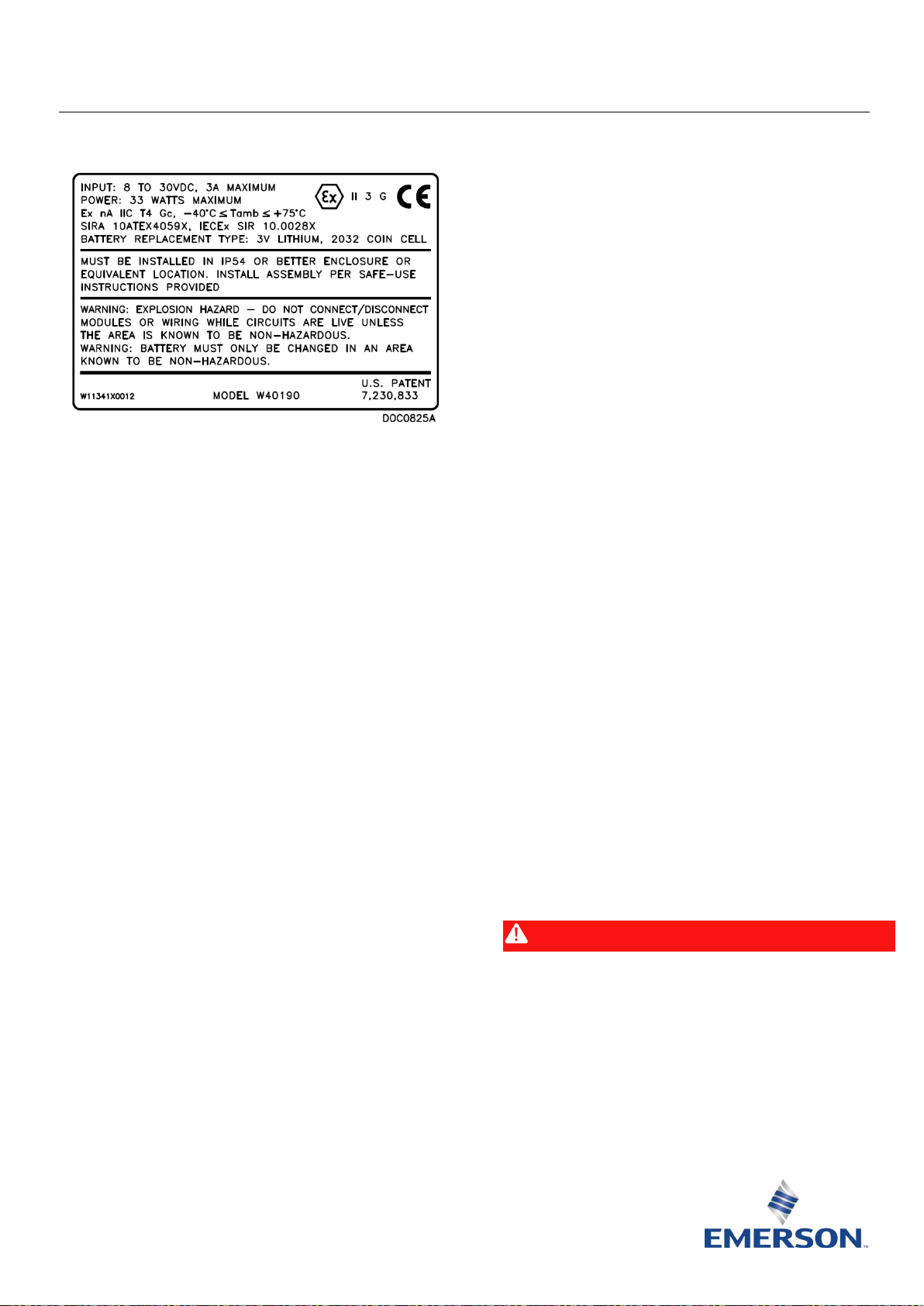
Instrucciones para un uso seguro – Administrador de caudal Emerson FloBoss 107
Parte D301594X412
Administrador de caudal Emerson FloBoss™ 107
Un personal capacitado correctamente debe ser
el encargado de instalar el equipo según el código
profesional correspondiente (generalmente
IEC EN 60079-14).
No es necesario armar o desarmar el equipo.
Con respecto a la seguridad, no es necesario revisar
si hay un funcionamiento adecuado.
No se requieren ajustes por parte del usuario.
La inspección periódica regular del equipo la debe
hacer el personal capacitado correctamente según el
código profesional correspondiente con el fin de
Figura 1. Placa de identificación del administrador de caudal
FloBoss 107 (se muestra la versión ATEX)
Use este documento de instrucciones de uso seguro (SUI)
con el Manual de instrucciones del administrador de caudal
FloBoss 107 (parte D301232X02). Para conocer todas las
precauciones y las descripciones de instalación y los
procedimientos de solución de problemas, consulte
ese manual.
Condiciones especiales para un uso seguro de
FloBoss 107
Las conexiones que se hacen al puerto de LOI
(conector tipo D) deben estar aseguradas en su lugar
de manera mecánica con conexiones atornilladas
adecuadas que eviten la desconexión y el aflojamiento
durante el uso.
Al usar las conexiones Ethernet, la conexión RJ45
(Ethernet) del módulo de comunicaciones mejoradas
debe tener un conector de acoplamiento con un
sujetador de seguridad válido para evitar la
desconexión y el aflojamiento durante el uso.
El conector USB en el módulo de comunicaciones
mejoradas no se puede usar a menos que se conozca
que el área no es peligrosa (no inflamable).
Instale el FB107 dentro de una carcasa IP54 adecuada
y certificada según ATEX o IECEx, o una de mejor
calidad.
El área donde se usará el equipo debe tener un grado
de contaminación mínimo de 2, según la definición de
IEC 60664-1 (es decir, el entorno no debe tener
contaminación conductiva y el equipo se debe instalar
en el interior o en un lugar protegido).
El equipo se puede usar en la zona 2 con gases
inflamables.
El equipo se puede usar en presencia de vapores y
gases inflamables con grupos de aparatos IIC o IIB o IIA
y con temperaturas clase T1 o T2 o T3 o T4.
El equipo está certificado para usarse en temperaturas
ambiente dentro de los rangos de –40 °C a +75 °C, y
no se debe usar fuera de este rango.
garantizar que se mantenga en condiciones
satisfactorias.
El usuario no debe reparar el equipo. La reparación de
este equipo debe ser efectuada por el fabricante o los
agentes aprobados siguiendo el código profesional
correspondiente.
El equipo no contiene ninguna otra pieza que deba
reemplazar el cliente.
En ciertas circunstancias extremas, las partes no
metálicas de la carcasa de este equipo pueden ser
capaces de generar un nivel de carga electrostática
capaz de generar una ignición. Por lo tanto, el equipo
debe limpiarse únicamente con un pañuelo húmedo.
Si existe la posibilidad de que el equipo tenga
contacto con sustancias agresivas (como gases o
líquidos ácidos que puedan estropear metales o
solventes que puedan afectar materiales poliméricos),
es entonces responsabilidad del usuario tomar las
precauciones pertinentes que prevengan efectos
adversos al equipo y garantice así que el tipo de
protección no haya sido comprometido.
Declaración de conformidad
Por la presente, Remote Automation Solutions declara que
el producto FloBoss 107 cumple con los requisitos
esenciales y otras provisiones relevantes de las directivas
europeas 2014/30/EU (EMC) y 2014/34/EU (ATEX).
PELIGRO
Al instalar unidades en un área peligrosa, asegúrese de
que todos los componentes seleccionados para la
instalación estén diseñados para su uso en este tipo de
entornos. La instalación y el mantenimiento deben
llevarse a cabo sólo cuando se tenga la seguridad de que el
área no es peligrosa. La instalación en un área peligrosa
podría ocasionar lesiones personales o daños materiales.
Siempre apague la alimentación a FloBoss antes
de intentar cualquier tipo de cableado. El cableado de
equipos con alimentación conectada podría ocasionar
lesiones personales o daños materiales.
Junio de 2021
Soluciones de automatización remota
Page 43

Instrucciones para un uso seguro – Administrador de caudal Emerson FloBoss 107
Especificaciones
ALIMENTACIÓN
Entrada de carga de alimentación externa:
Entrada:
CARACTERÍSTICAS AMBIENTALES
Temperatura ambiente operativa:
Temperatura de almacenamiento:
Humedad de operación:
PESO
APROBACIONES
ATEX/IECEx
4X Ø4.8
]
[
0.19
134.4
5.29
]
[
]
6.22
[
158.0
][
5.00
127.0
]
[
15.5
0.61
][
9.1
0.36
196.1
7.72
[ ]
][
177.8
7.00
Parte D301594X412
Junio de 2021
Para evitar daños en los circuitos al trabajar dentro de la
unidad, utilice las debidas precauciones contra descargas
electrostáticas, como el uso de una pulsera antiestática
conectada a tierra.
No abra las cubiertas a menos que se sepa que el área no
es peligrosa.
8–30 V cc,
protección contra la inversión de polaridad.
8–30 V cc, 3A máx., 33 vatios máx.
–40 a 75 °C.
–50 a 85 °C.
5 a 95 %, sin condensación.
0,76 kg (unidad principal de 4 ranuras y un módulo de
CPU).
Solo la unidad principal. Colóquela según lo desee
en la placa de montaje de la carcasa y ubique los
orificios de montaje en la placa con el FB107
como plantilla. Vea la
Figura 2 para obtener las
dimensiones del FB107. Perfore y rosque orificios
de montaje en la placa con una rosca de 8-32 UNC.
Coloque el FB107 sobre las ubicaciones roscadas y
conecte la placa con los cuatro tornillos de 8-32
UNC x 1,00 pulg provistos. Ajuste los tornillos en
un par de 1,1 a 1,4 N-m aproximadamente.
Nota: Si se sustituyen los tornillos métricos,
use tornillos de cabeza reforzada para
evitar fracturar la carcasa de plástico
durante el ajuste.
Evaluado por las siguientes normas:
EN 60079-0 (2012/A11:2013)
EN 60079-15 (2010)
IEC 60079-0 (2011 Ed 6)
IEC 60079-15 (2010 Ed 4)
Certificado por Sira como modelo W40190.
ATEX Cert Sira 10ATEX4059X
IECEx Cert IECEx SIR 10.0028X
Marcas de productos para ubicaciones peligrosas:
Ex nA IIC T4 Gc, –40 °C ≤ T
amb
Se requieren las siguientes herramientas para la
instalación, el mantenimiento y la solución de problemas:
II 3 G.
Computadora personal con Microsoft
Windows 8.1 o Windows 10 y el software de
configuración Emerson Field Tools (que proporciona
el software de configuración ROCLINK™ 800).
Software de configuración ROCLINK 800.
Destornillador Phillips (cruciforme).
Destornillador de cabeza plana.
1. El FB107 se recibe en una caja. Retírelo de la caja.
≤ +75 °C
®
Windows® 7,
Figura 2. Dimensiones del FB107
Unidad principal montada sobre el panel del
adaptador. Colóquela según lo desee en la placa
de montaje de la carcasa y ubique los orificios de
montaje en la placa con las ranuras del panel del
adaptador como plantilla. Vea la
Figura 3 para
obtener las dimensiones del panel del adaptador.
Perfore y rosque orificios de montaje en la placa con
una rosca de 8-32 UNC. Coloque el FB107 con el
panel del adaptador sobre las ubicaciones roscadas
y conecte la placa con los cuatro tornillos de 8-32
UNC x 0,38 pulg provistos. Ajuste los tornillos con
firmeza.
2. El FB107 se envía en una de las cuatro configuraciones
principales según el pedido. Instale el FB107 en una
carcasa IP54 adecuada y aprobada por ATEX o IECEx,
o una de mejor calidad, según las siguientes pautas:
2 www.Emerson.com/RemoteAutomation
Figura 3. Dimensiones del panel
Page 44

Instrucciones para un uso seguro – Administrador de caudal Emerson FloBoss 107
31.8
1.25
[ ]
5.00
127.0
[ ]
127.0
5.00
[ ]
317.5
12.50
[ ]
11.12
[
282.5
]
3.40
86.4
[ ]
0.38
9.5
[
]
7.00
[
177.8
]
][
7.75
196.8
Parte D301594X412
Junio de 2021
Unidad principal y estante de expansión. Coloque
la unidad principal sobre la placa de montaje de la
carcasa y ubique los orificios de montaje en la placa
con el FB107 como plantilla. Vea la
Figura 4 para
obtener las dimensiones de la unidad principal con
el estante de expansión. Perfore y rosque orificios
de montaje en la placa con una rosca de 8-32 UNC.
Coloque la unidad principal sobre las ubicaciones
roscadas y conecte la placa con los cuatro tornillos
de 8-32 UNC x 1,00 pulg provistos. No apriete por
completo. Enchufe el estante de expansión en la
unidad principal y, mientras se encuentre en su
posición, marque las ubicaciones de los orificios
de montaje del estante. Retire cuidadosamente el
estante de expansión y, luego, perfore y rosque los
orificios de montaje en la placa con una rosca de
8-32 UNC. Enchufe el estante de expansión en la
unidad principal y conecte la placa con los cuatro
tornillos de 8-32 UNC x 1,00 pulg provistos. Ajuste
los ocho tornillos de montaje en un par de 1,1 a 1,4
N-m aproximadamente.
Nota: Si se sustituyen los tornillos métricos, use
tornillos de cabeza reforzada para evitar
fracturar la carcasa de plástico durante el
ajuste.
Nota: Si se sustituyen los tornillos métricos, use
tornillos de cabeza reforzada para evitar
fracturar la carcasa de plástico durante el
ajuste.
Figura 5. Dimensiones del panel
3. Pruebe la potencia eléctrica en el FB107 en el conjunto
de la carcasa. Realice la prueba al provocar un
cortocircuito en las conexiones de AUX PWR IN, DVS y
DISPLAY, y en el panel del adaptador o en una
conexión a tierra de la planta local. Use uno de los
siguientes voltajes:
500 V r.m.s (+5 %, –0 %) durante 60 segundos
700 V c.c. (+5 %, –0 %) durante 60 segundos
No exceda una corriente de caudal máxima de 5 mA;
asegúrese de que no haya una avería o descarga.
4. Busque un lugar adecuado para el conjunto de la
carcasa. Cuando elija un lugar para la instalación,
asegúrese de revisar todos los espacios vacíos.
Proporcione suficiente espacio para el cableado y el
mantenimiento. Selle cualquier orificio que haya en la
carcasa para mantener la clasificación IP54. Asegúrese
de que el montaje del conjunto cumpla con todos los
requisitos de peso y de que la instalación cumpla con
Figura 4. Dimensiones del estante de expansión y el FB107
Unidad principal con estante de expansión
montada sobre el panel del adaptador. Colóquela
según lo desee en la placa de montaje de la carcasa
y ubique los orificios de montaje en la placa con el
conjunto del FB107 como plantilla. Vea la
Figura 5
para obtener las dimensiones del panel del
adaptador. Perfore y rosque orificios de montaje en
la placa con una rosca de 8-32 UNC. Coloque el
conjunto del FB107 sobre las ubicaciones roscadas
y conecte la placa con los cuatro tornillos de 8-32
UNC x 1,00 pulg provistos. Ajuste los cuatro
los códigos de construcción locales.
5. Conecte adecuadamente el FB107 a tierra.
La puesta a tierra adecuada del FB107 contribuye a
reducir los efectos del ruido eléctrico en el
funcionamiento de la unidad y la protege contra
rayos. El FB107 proporciona protección contra rayos
para el cableado de campo integrado para las
entradas y salidas.
Todas las conexiones a tierra deben tener una varilla a
tierra o rejilla de tierra con impedancia de 2,0 ohmios o
menos, medida con un probador de sistemas de tierra.
El conductor de tierra debe tener una resistencia de 1
ohmio o menos entre la conexión a tierra de la carcasa
del FB107 y la varilla o la rejilla de tierra.
tornillos de montaje en un par de 1,1 a 1,4 N-m
aproximadamente.
www.Emerson.com/RemoteAutomation 3
Si la impedancia de la tubería a tierra es mayor que
2 ohmios, aísle eléctricamente al FB107 e instale una
varilla o un sistema de rejilla a tierra.
Page 45

Instrucciones para un uso seguro – Administrador de caudal Emerson FloBoss 107
Parte D301594X412
Junio de 2021
Para el cableado de señal de E/S se recomienda un
cable aislado, blindado y en par trenzado. El par
trenzado y el blindaje reducen al mínimo los errores
de señal causados por EMI (interferencia
electromagnética), RFI (interferencia de
radiofrecuencia) y transitorios.
6. Conecte la alimentación del FB107, los dispositivos de
E/S y los dispositivos de comunicación. Las conexiones
externas (o los terminales de campo) se encuentran
en la placa de terminación. El bloque de terminales
acepta cables de hasta 16 AWG de tamaño.
Los conectores de FB107 usan terminales de
compresión. La terminación de alimentación de
entrada (IN+/IN–) usa un conector extraíble y admite
un cableado de hasta 16 AWG de tamaño. En todos los
casos, haga las conexiones pelando el extremo del
cable (6 mm como máximo), insertando el extremo
pelado en el sujetador debajo del tornillo de
terminación y, luego, ajustando el tornillo a 0,25 N-m.
Los cables insertados deben tener un mínimo de cable
pelado expuesto para evitar cortocircuitos. Permita
que haya algo de espacio suficiente cuando haga las
conexiones para evitar la presión.
PELIGRO
No ajuste demasiado el par de los tornillos del
conector.
NOTAR: Revise la polaridad de la alimentación de
entrada
7. Conecte la alimentación del FB107.
8. Configure el FB107 antes de ponerlo en
funcionamiento. Debe configurar el dispositivo con el
software de configuración ROCLINK 800, que se
ejecute en una computadora. Normalmente, debe
conectar la computadora al puerto de LOI del FB107
para transferir los datos de configuración al FB107,
aunque también puede hacer las configuraciones
fuera de línea y luego cargarlas al FB107.
antes de encender la alimentación.
analógicas de diagnóstico, voltaje lógico (E1), voltaje
de batería (E2) y temperatura de placa/batería (E5), no
están diseñadas para calibrarse.
Con los puntos de terminación de E/S opcionales,
calibre la entrada analógica con ROCLINK 800.
El procedimiento de calibración para estas entradas
analógicas se describe en el Manual de usuario del
software de configuración ROCLINK 800 (para FloBoss
107) (parte D301249X012).
10. Para solucionar problemas con el FB107, identifique
si el problema es con la configuración o con el
hardware. Verifique (con ROCLINK 800) la
configuración para identificar cualquier ajuste
incorrecto. Inspeccione si hay daños en el hardware.
Inspeccione las placas de circuitos para encontrar
errores de ubicación de conexiones.
Si los problemas con el FB107 parecen estar
relacionados con el software, intente restablecer el
FB107 con un inicio en caliente, un inicio en frío o un
restablecimiento.
Nota: El restablecimiento del firmware puede
restaurar el dispositivo y su configuración a los
ajustes de fábrica. Asegúrese de haber
guardado cualquier ajuste de configuración en
su computadora o en algún dispositivo
extraíble.
Si tiene problemas que parezcan estar relacionados
con el hardware, revise el cableado. Si todavía tiene
problemas, comuníquese con la oficina de ventas local
para obtener una autorización de devolución.
11. Para quitar al FB107 del servicio:
Verifique que el área sea segura.
Desconecte el suministro eléctrico de la unidad.
Quite todas las conexiones externas del cableado.
Quite al FB107 de su carcasa.
12. Coloque al FB107 en un contenedor adecuado para el
transporte o el envío.
El firmware del FB107 brinda valores predeterminados
para todos los parámetros. Si los valores
predeterminados son aceptables para su aplicación,
déjelos como los encontró. Debe usar ROCLINK 800
para ajustar los valores del parámetro. Consulte el
Manual de usuario del software de configuración ROCLINK
800 (para FloBoss 107) (parte D301249X012).
9. Las rutinas de calibración admiten una calibración de
5 puntos, con los tres puntos intermedios calibrados
en cualquier orden. Calibre primero la lectura inferior
o cero, seguida por la lectura superior o de escala
completa. Los tres puntos intermedios se pueden
calibrar a continuación, si lo desea. Las entradas
4 www.Emerson.com/RemoteAutomation
Page 46

Instrucciones para un uso seguro – Administrador de caudal Emerson FloBoss 107
Oficinas centrales,
Norteamérica y Latinoamérica:
Aunque se han realizado todos los esfuerzos
sponsabilidad de la selección, el uso y
y/o al usuari o final.
Europa
Oriente Medio/África:
Asia-Pacífico:
Tel. +65 6777 8211| Fax +65 6777 0947
Para recibir servicio al cliente y soporte técnico,
visite www.Emerson.com/SupportNet.
Parte D301594X412
Junio de 2021
Emerson Automation Solutions
Remote Automation Solutions
6005 Rogerdale Road
Houston, TX 77072 EE. UU.
Tel. +1 281 879 2699 | Fax +1 281 988
4445
www.Emerson.com/RemoteAutomation
:
Emerson Automation Solutions
Remote Automation Solutions
Unit 1, Waterfront Business Park
Dudley Road, Brierley Hill
Dudley DY5 1LX UK
Tel. +44 1384 487200
Emerson Automation Solutions
Remote Automation Solutions
Emerson FZE
P.O. Box 17033
Jebel Ali Free Zone – South 2
Dubái E. A. U.
Tel. +971 4 8118100 | Fax +971 4 8865465
Emerson Automation Solutions
Remote Automation Solutions
1 Pandan Crescent
Singapur 128461
© 2010–2021 Remote Automation Solutions, una unidad comercial de Emerson Automation
Solutions. Reservados todos los derechos.
Esta publicació n tiene fines exclusi vamente informativos.
para garantiz ar su exactitud, esta p ublicación no incluye g arantías, explícitas o implícitas, incluyend o
los productos o servicios descritos o su uso o aplicación. Remote Automation Solutions se reserva el
derecho de modificar o mejorar los diseños o especificaciones de dichos productos en cualquier
momento, sin previo aviso. Todas las ventas están regidas por los términos y condiciones de RAS, los
cuales se encuentran disponibles si se solicitan. RAS no acepta re
el mantenimie nto correctos de cualq uier producto, que corre sponde exclusivamente al comprador
Soluciones de automatización remota
 Loading...