

Page 1

Remote Automation Solutions
Part Number D301232X012
May 2018
FloBoss™ 107 Flow Manager
Instruction Manual
Page 2

FloBoss 107 Flow Manager Instruction Manual
ii Revised May-2018
System Training
A well-trained workforce is critical to the success of your operation. Knowing how to
correctly install, configure, program, calibrate, and trouble-shoot your Emerson equipment
provides your engineers and technicians with the skills and confidence to optimize your
investment. Remote Automation Solutions offers a variety of ways for your personnel to
acquire essential system expertise. Our full-time professional instructors can conduct
classroom training at several of our corporate offices, at your site, or even at your regional
Emerson office. You can also receive the same quality training via our live, interactive
Emerson Virtual Classroom and save on travel costs. For our complete schedule and further
information, contact the Remote Automation Solutions Training Department at 800-338-8158
or email us at education@emerson.com.
Page 3

FloBoss 107 Flow Manager Instruction Manual
Revised May-2018 Contents iii
Contents
Chapter 1 – General Information 1-1
1.1 Scope of Manual ............................................................................................................................1-2
1.2 FloBoss 107 Overview ...................................................................................................................1-2
1.3 Hardware ........................................................................................................................................1-5
1.3.1 Processor and Memory ....................................................................................................1-6
1.3.2 Backplane ........................................................................................................................1-6
1.3.3 Expansion Rack ...............................................................................................................1-6
1.3.4 Central Processing Unit (CPU) ........................................................................................1-6
1.3.5 Battery and Super-capacitor ............................................................................................1-8
1.3.6 Built-in Inputs and Outputs ...............................................................................................1-8
1.3.7 Built-in Communications ..................................................................................................1-8
1.3.8 Built-in Resistance Thermal Device (RTD) ................................................................... 1-10
1.3.9 Built-in Loop Output Power ........................................................................................... 1-10
1.3.10 Optional Inputs and Outputs ......................................................................................... 1-10
1.3.11 Optional Communication Modules – COM3 ................................................................. 1-11
1.3.12 Optional Multi-Variable Sensor (MVS) .......................................................................... 1-12
1.3.13 Optional Integral Sensors ............................................................................................. 1-12
1.3.14 Optional License Key .................................................................................................... 1-12
1.3.15 Optional Enclosures ...................................................................................................... 1-12
1.3.16 Optional LCD Touchpad ............................................................................................... 1-13
1.4 Firmware ..................................................................................................................................... 1-14
1.4.1 History Points ................................................................................................................ 1-15
1.4.2 Alarm Log ...................................................................................................................... 1-16
1.4.3 Event Log ...................................................................................................................... 1-17
1.4.4 Security ......................................................................................................................... 1-17
1.4.5 I/O Database ................................................................................................................. 1-18
1.4.6 Function Sequence Tables (FST) ................................................................................. 1-18
1.4.7 PID Control.................................................................................................................... 1-18
1.4.8 Spontaneous-Report-By-Exception (SRBX) Alarming .................................................. 1-19
1.4.9 Softpoints ...................................................................................................................... 1-19
1.4.10 Opcodes ........................................................................................................................ 1-19
1.4.11 Pass Through Communications .................................................................................... 1-19
1.4.12 ROC and Modbus Protocols ......................................................................................... 1-19
1.4.13 User C Programs .......................................................................................................... 1-20
1.5 ROCLINK™ 800 Configuration Software ..................................................................................... 1-20
1.6 Product Electronics ..................................................................................................................... 1-22
1.6.1 Real-Time Clock ........................................................................................................... 1-22
1.6.2 Diagnostic Monitoring ................................................................................................... 1-22
1.6.3 Automatic Self Tests ..................................................................................................... 1-22
1.6.4 Low Power Mode .......................................................................................................... 1-23
1.7 Flow Measurements .................................................................................................................... 1-23
1.8 Security Gateway ........................................................................................................................ 1-24
1.9 Additional Technical Information ................................................................................................. 1-25
Chapter 2 – Installation and Use 2-1
2.1 Installation Requirements ...............................................................................................................2-1
2.1.1 Environmental Requirements...........................................................................................2-1
2.1.2 Site Requirements ...........................................................................................................2-2
2.1.3 Compliance with Hazardous Area Standards ..................................................................2-4
2.1.4 Power Installation Requirements .....................................................................................2-4
2.1.5 Grounding Installation Requirements ..............................................................................2-5
2.1.6 I/O Wiring Requirements ..................................................................................................2-6
Page 4

FloBoss 107 Flow Manager Instruction Manual
iv Contents Revised May-2018
2.2 Installing the FloBoss 107 and Expansion Rack ............................................................................ 2-7
2.2.1 Required Tools ................................................................................................................. 2-7
2.2.2 Installing the FloBoss 107 without an Expansion Rack ................................................... 2-7
2.2.3 Installing the FloBoss with an Expansion Rack ............................................................... 2-8
2.2.4 Removing an Expansion Rack ....................................................................................... 2-10
2.2.5 Removing and Installing Module Slot Covers ................................................................ 2-11
2.2.6 Removing and Installing Wire Channel Covers ............................................................. 2-11
2.3 Memory Backup Battery ............................................................................................................... 2-12
2.3.1 Removing and Installing the Battery .............................................................................. 2-12
2.4 Central Processor Unit (CPU) ...................................................................................................... 2-13
2.4.1 Removing the CPU Module ........................................................................................... 2-15
2.4.2 Installing the CPU Module ............................................................................................. 2-16
2.4.3 Resetting the CPU ......................................................................................................... 2-16
2.5 License Keys ................................................................................................................................ 2-16
2.6 Startup and Operation .................................................................................................................. 2-17
2.6.1 Startup ........................................................................................................................... 2-17
2.6.2 Operation ....................................................................................................................... 2-17
Chapter 3 – Power Connections 3-1
3.1 Power Input Descriptions ............................................................................................................... 3-1
3.2 Determining Power Consumption .................................................................................................. 3-3
3.2.1 Summary .......................................................................................................................... 3-6
3.3 Wiring Connections ........................................................................................................................ 3-6
3.4 Wiring Power to the CPU Module .................................................................................................. 3-7
Chapter 4 – Inputs and Outputs 4-1
4.1 I/O Description ............................................................................................................................... 4-1
4.2 Installing a Module ......................................................................................................................... 4-5
4.3 Removing a Module ....................................................................................................................... 4-6
4.4 Wiring a Module ............................................................................................................................. 4-7
4.5 Selecting the Type of I/O ................................................................................................................ 4-7
4.6 Analog Inputs (AI) .......................................................................................................................... 4-9
4.6.1 Wiring the Analog Inputs .................................................................................................. 4-9
4.7 8-Point Analog Input/Digital Input (AI/DI) Module ........................................................................ 4-11
4.7.1 Wiring the 8-Point AI/DI ................................................................................................. 4-11
4.8 Analog Outputs (AO) .................................................................................................................... 4-13
4.8.1 Wiring the Analog Outputs ............................................................................................. 4-13
4.9 Discrete Inputs (DI) ...................................................................................................................... 4-14
4.9.1 Wiring the Discrete Inputs .............................................................................................. 4-15
4.10 Discrete Outputs (DO) .................................................................................................................. 4-15
4.10.1 Wiring the Discrete Outputs ........................................................................................... 4-16
4.11 Discrete Outputs Relay (DOR) Module ........................................................................................ 4-17
4.11.1 Wiring the Discrete Output Relays ................................................................................. 4-18
4.12 Pulse Inputs (PI) ........................................................................................................................... 4-19
4.12.1 Wiring the Pulse Inputs .................................................................................................. 4-19
4.13 Application (APP 485) Module ..................................................................................................... 4-20
4.13.1 Wiring the Application Module ....................................................................................... 4-20
4.14 Resistance Temperature Detector (RTD) Input ........................................................................... 4-22
4.14.1 Wiring the RTD Input ..................................................................................................... 4-22
4.15 6-Point AO/DO Module ................................................................................................................ 4-23
4.15.1 Wiring the 6-Point AO/DO Module ................................................................................. 4-24
4.16 HART® Module ............................................................................................................................. 4-24
4.16.1 Wiring the HART Module ............................................................................................... 4-25
4.17 Resistance Temperature Detector (RTD) Module ....................................................................... 4-26
4.17.1 Wiring the RTD Module.................................................................................................. 4-26
4.18 IEC 62591 Module ....................................................................................................................... 4-27
Page 5

FloBoss 107 Flow Manager Instruction Manual
Revised May-2018 Contents v
4.18.1 Wiring the IEC 62591 Module ....................................................................................... 4-28
4.19 Additional Technical Information ................................................................................................. 4-28
Chapter 5 – Communications 5-1
5.1 Communications Overview ............................................................................................................5-1
5.2 Installing/Removing a Communication Module ..............................................................................5-5
5.3 Wiring the Local Operator Interface (LOI) Port ..............................................................................5-5
5.3.1 Using the LOI ...................................................................................................................5-6
5.4 Wiring EIA-485 (RS-485) Communications ...................................................................................5-6
5.5 Wiring EIA-232 (RS-232) Communications ...................................................................................5-7
5.6 Liquid Crystal Display (LCD) Touchpad .........................................................................................5-8
5.7 Enhanced Communication Module (ECM) .....................................................................................5-9
5.7.1 Activating the USB Port ................................................................................................ 5-10
5.8 Dial-Up Modem Module .............................................................................................................. 5-15
5.9 Network Radio Module (NRM) .................................................................................................... 5-16
5.9.1 Installing the NRM ......................................................................................................... 5-17
5.10 Additional Technical Information ................................................................................................. 5-17
Chapter 6 – Sensors and Transducers 6-1
6.1 Multi-Variable Sensor (MVS) Module Overview .............................................................................6-1
6.1.1 Installing/Removing an MVS Module ...............................................................................6-4
6.1.2 Configuring a Multi-drop MVS Module Setup ..................................................................6-4
6.1.3 Lightning Protection .........................................................................................................6-6
6.2 Dual Variable Sensor (DVS) Overview ..........................................................................................6-7
6.2.1 Installing/Removing a DVS ..............................................................................................6-8
6.2.2 Physically Connecting a DVS ..........................................................................................6-9
6.2.3 Configuring a DVS ........................................................................................................ 6-10
6.3 Pressure Module (PIM) Overview ............................................................................................... 6-10
6.3.1 Installing/Removing a Pressure Module ....................................................................... 6-11
6.3.2 Configuring a Pressure Module .................................................................................... 6-13
6.4 Additional Technical Information ................................................................................................. 6-14
Chapter 7 – Troubleshooting 7-1
7.1 General Guidelines.........................................................................................................................7-1
7.2 Graphical User Interface (GUI) ......................................................................................................7-2
7.3 Checklists .......................................................................................................................................7-4
7.3.1 LEDs ................................................................................................................................7-4
7.3.2 Serial Communications ....................................................................................................7-4
7.3.3 Inputs/Outputs ..................................................................................................................7-5
7.3.4 Preserving Configuration and Log Data ...........................................................................7-6
7.3.5 ROCLINK 800 Configuration Software ............................................................................7-6
7.3.6 Powering Up.....................................................................................................................7-7
7.3.7 Multi-Variable Sensor (MVS) ...........................................................................................7-7
7.3.8 Resistance Temperature Detector (RTD) ........................................................................7-7
7.3.9 IEC 62591 Module ...........................................................................................................7-8
7.3.10 Network Radio Module (NRM) .........................................................................................7-8
7.4 Procedures .....................................................................................................................................7-8
7.4.1 Resetting the FB107 ........................................................................................................7-9
7.4.2 Restarting and Reconfiguring the FB107 .........................................................................7-9
7.4.3 Troubleshooting Analog Inputs ..................................................................................... 7-10
7.4.4 Troubleshooting Analog Outputs .................................................................................. 7-11
7.4.5 Troubleshooting Discrete Inputs ................................................................................... 7-12
7.4.6 Troubleshooting Discrete Outputs ................................................................................ 7-12
7.4.7 Troubleshooting Pulse Inputs ....................................................................................... 7-13
Page 6

FloBoss 107 Flow Manager Instruction Manual
vi Contents Revised May-2018
7.4.8 Troubleshooting RTD Inputs .......................................................................................... 7-13
7.4.9 Troubleshooting the Multi-Variable Sensor (MVS) ........................................................ 7-15
7.4.10 Troubleshooting the Enhanced Comm Module (ECM) .................................................. 7-16
7.4.11 Troubleshooting the Dual Variable Sensor (DVS) ......................................................... 7-16
7.4.12 Troubleshooting the Pressure Module (PIM) ................................................................. 7-17
7.4.13 Troubleshooting AI/DI .................................................................................................... 7-18
7.4.14 Troubleshooting the Discrete Output Relay (DOR) ....................................................... 7-18
Appendix A – Glossary A-1
Index I-1
Page 7

FloBoss 107 Flow Manager Instruction Manual
Revised May-2018 General Information 1-1
Chapter 1 – General Information
In This Chapter
1.1 Scope of Manual................................................................................. 1-2
1.2 FloBoss 107 Overview ....................................................................... 1-2
1.3 Hardware ............................................................................................ 1-5
1.3.1 Processor and Memory ......................................................... 1-6
1.3.2 Backplane .............................................................................. 1-6
1.3.3 Expansion Rack .................................................................... 1-6
1.3.4 Central Processing Unit (CPU) ............................................. 1-6
1.3.5 Battery and Super-capacitor.................................................. 1-8
1.3.6 Built-in Inputs and Outputs .................................................... 1-8
1.3.7 Built-in Communications ........................................................ 1-8
1.3.8 Built-in Resistance Thermal Device (RTD) ......................... 1-10
1.3.9 Built-in Loop Output Power ................................................. 1-10
1.3.10 Optional Inputs and Outputs................................................ 1-10
1.3.11 Optional Communication Modules – COM3 ........................ 1-11
1.3.12 Optional Multi-Variable Sensor (MVS) ................................ 1-12
1.3.13 Optional Integral Sensors .................................................... 1-12
1.3.14 Optional License Key .......................................................... 1-12
1.3.15 Optional Enclosures ............................................................ 1-12
1.3.16 Optional LCD Touchpad ...................................................... 1-13
1.4 Firmware ........................................................................................... 1-14
1.4.1 History Points ...................................................................... 1-15
1.4.2 Alarm Log ............................................................................ 1-16
1.4.3 Event Log ............................................................................ 1-17
1.4.4 Security ................................................................................ 1-17
1.4.5 I/O Database ....................................................................... 1-18
1.4.6 Function Sequence Tables (FST) ....................................... 1-18
1.4.7 PID Control .......................................................................... 1-18
1.4.8 Spontaneous-Report-By-Exception (SRBX) Alarming ........ 1-19
1.4.9 Softpoints............................................................................. 1-19
1.4.10 Opcodes .............................................................................. 1-19
1.4.11 Pass Through Communications .......................................... 1-19
1.4.12 ROC and Modbus Protocols................................................ 1-19
1.4.13 User C Programs ................................................................. 1-20
1.5 ROCLINK™ 800 Configuration Software .......................................... 1-20
1.6 Product Electronics .......................................................................... 1-22
1.6.1 Real-Time Clock .................................................................. 1-22
1.6.2 Diagnostic Monitoring .......................................................... 1-22
1.6.3 Automatic Self Tests ........................................................... 1-22
1.6.4 Low Power Mode ................................................................. 1-23
1.7 Flow Measurements ......................................................................... 1-23
1.8 Security Gateway ............................................................................. 1-24
1.9 Additional Technical Information ...................................................... 1-25
This manual describes the FloBoss™ 107 Flow Manager (“FB107”), part
of the family of FloBoss flow computers manufactured by Remote
Automation Solutions, a division of Emerson Process Management. For
information about the software you use to configure the FB107, refer to
the ROCLINK™ 800 Configuration Software User Manual (for FloBoss
107) (part D301249X012).
Page 8

FloBoss 107 Manager Instruction Manual
1-2 General Information Revised May-2018
This chapter provides an overview of the FB107 and its components.
1.1 Scope of Manual
This manual contains the following chapters:
Chapter 1
General Information
Provides an overview of the hardware and firmware
for the FB107 base unit and the expansion rack.
Chapter 2
Installation and Use
Provides information on installation, tools, wiring,
and other essential elements of the FB107.
Chapter 3
Power Connections
Provides information on determining power
requirements for the FB107.
Chapter 4
Inputs and Outputs
Provides information for the input/output (I/O)
modules, CPU I/O assembly, and the RTD input.
Chapter 5
Communications
Provides information for the built-in communication
ports and the optional communication modules.
Chapter 6
Sensors and
Transducers
Provides information on the optional Multi-Variable
Sensor (MVS), Dual Variable Sensor (DVS), and
Pulse Input modules.
Chapter 7
Troubleshooting
Provides information on diagnosing and correcting
problems.
Glossary
Provides definitions of acronyms and terms.
Index
Provides an alphabetic listing of items and topics
contained in this manual.
1.2 FloBoss 107 Overview
A 32-bit microprocessor-based electronic flow computer, the FB107
electronically measures, monitors, and manages flow. This economical
flow computer reliably and accurately performs flow calculations,
temperature measurements, and data archival.
Note: You configure the functionality of the FB107 and monitor its
operation using a personal computer (PC) running ROCLINK 800
(“ROCLINK 800”) software.
The FB107 can measure up to four meter runs through a variety of
devices, such as an orifice plate, turbine meter, or other pulse-generating
devices. Meter inputs may also use analog transmitters. For multiple
differential pressure-run applications, you can add an optional MultipleVariable Sensor (MVS) module to provide an interface to remote MVS
transmitters.
The FB107 performs minute, hourly, daily, and minimum / maximum
historical data archival for standard history and a configurable time
interval archival for extended history. As the electronic solution to
replace traditional paper charting, the FB107 records the corrected flow
for differential or pulse counts and stores the data.
The FB107 computes flow for both volume and energy. It provides onsite functionality and supports remote monitoring, measurement, data
archival, communications, and control. It stores the results of the flow
Page 9

FloBoss 107 Flow Manager Instruction Manual
Revised May-2018 General Information 1-3
calculations in memory, which can then be and can be communicated to
an external device either on demand or periodically.
The FB107 design allows you to configure specific applications,
including those requiring logic and sequencing control using a Function
Sequence Table (FST).
A
Local (LOI) Communication Port
B
Slot 0 = CPU Module
C
CPU I/O Assembly
D
Input Power Connector
E
Memory Backup Battery Connector
F
Slot 3 = I/O or MVS module
G
Slot 2 = I/O, MVS module, or COM module (COM2)
H
Slot 1 = I/O, MVS, or COM module (COM3)
I
Wire Channel Cover
J
Display Connector
K
Integral Sensor Connector
Figure 1-1. FloBoss 107 Base Unit
F
A
G
C
B
D
E
J
I
H
K
Page 10

FloBoss 107 Manager Instruction Manual
1-4 General Information Revised May-2018
A
Slot 4 = I/O or MVS module
B
Slot 5 = I/O or MVS module
C
Connects to FloBoss 107 base unit
D
Slot 7 = I/O or MVS module
E
Slot 6 = I/O or MVS module
F
Wire Channel Cover
Figure 1-2. FloBoss 107 Expansion Rack
D
A
F
E
B
C
Page 11

FloBoss 107 Flow Manager Instruction Manual
Revised May-2018 General Information 1-5
Figure 1-3. FloBoss 107 with Expansion Rack
The FB107 provides the following components and features:
▪ 32-bit processor board, inter-connect board, and backplane board.
▪ Central processing unit (CPU).
▪ Field-upgradeable 2 MB flash ROM (read only memory).
▪ 2 MB battery backed-up RAM (random access memory) storage.
▪ Two-, three-, or four-wire 100-ohm resistance thermal device (RTD)
input.
▪ Battery and super-capacitor backed memory retention to provide short
and longer-term data, configuration, and operational integrity when
the FB107 is not in service or is in storage.
▪ Three built-in communication ports.
▪ Input power and output loop power.
▪ Extensive applications firmware.
1.3 Hardware
The FB107 is available with four basic configurations:
▪ Non-isolated CPU without I/O.
▪ Non-isolated CPU with six points of I/O.
▪ Isolated CPU without I/O.
▪ Isolated CPU with six points of I/O.
Note: Isolation occurs between the CPU and the field logic.
W
6
Page 12

FloBoss 107 Manager Instruction Manual
1-6 General Information Revised May-2018
The FB107 base unit has four slots. Slot 0 is reserved for the CPU
module, which provides three communication ports, an RTD, power
input, loop power output, system variables, and optional 6 points of I/O.
Slots 1 and 2 can each contain one communication module. Slots 1, 2,
and 3 can contain input/outputs (I/O), MVS, and application modules.
1.3.1 Processor and Memory
The FB107 derives processing power from a 32-bit CMOS
microprocessor. The microprocessor features a single 32-bit internal data
bus and a single 16-bit external data bus. The microprocessor has lowpower operating modes, including inactivity and low battery condition.
The FB107 has high-speed direct memory access.
The FB107 has 2 MB of static random access memory (SRAM) for
storing database, historical, configuration, alarms, and events data.
1.3.2 Backplane
The backplane board routes signals to and from the CPU to the I/O
modules, application modules, expansion rack, the Multi-Variable Sensor,
and communication modules.
1.3.3 Expansion Rack
The four-slot optional expansion rack (see Figure 1-3) enables the FB107
to expand its I/O capabilities to meet your needs. The expansion rack
supports optional I/O, MVS, and application modules.
1.3.4 Central Processing Unit (CPU)
The base unit on the FB107 has four slots. Slot 0 is for the CPU module.
The CPU provides connections to the field wiring including surge and
static discharge protection for the field wiring. Electronics include the
RTD circuits and the final I/O drivers/receivers.
The CPU components include:
▪ RTD input.
▪ Input power.
▪ Loop power output.
▪ Reset (RST) switch.
▪ System variables.
▪ Diagnostic monitoring.
▪ Real-time clock.
▪ Automatic self-tests.
▪ Power saving modes.
▪ Local operator interface (LOI) EIA-232 (RS-232).
▪ EIA-485 (RS-485) communications (COM1).
Page 13

FloBoss 107 Flow Manager Instruction Manual
Revised May-2018 General Information 1-7
▪ EIA-232 (RS-232) communications (COM2).
▪ Boot Flash – System initialization and diagnostics.
▪ SRAM (static random access memory) with battery backup – Data
logs and configuration.
▪ Flash ROM (Read-only memory) – Firmware image.
▪ 32-bit microprocessor and the real-time operating system (RTOS)
provide both hardware and software memory protection.
▪ Optional CPU I/O assembly and terminations (see Figure 1-4).
Figure 1-4. CPU
Page 14

FloBoss 107 Manager Instruction Manual
1-8 General Information Revised May-2018
1.3.5 Battery and Super-capacitor
A super capacitor (“super-cap”) and a coin type battery work together to
provide backup power for the static RAM and the real-time clock. This
helps to ensure retention of short and longer-term data, configuration, and
operational integrity when the FB107 is not in service or is in storage.
For information on replacing the battery, refer to Section 2.3.1, Removing
and Installing the Battery.
Note: The super-cap is not field-replaceable.
1.3.6 Built-in Inputs and Outputs
The built-in inputs and outputs (I/O) on the CPU consist of a 3- or 4-wire
100-ohm resistance thermal detector (RTD) input interface and five
diagnostic analog inputs (AI) that monitor the:
▪ Logical voltage.
▪ Battery voltage from the backplane voltage input connector.
▪ Charge in voltage originating from the CPU power input.
▪ System milliamps originating from the power input from the CPU.
▪ Board temperature originating at the CPU.
1.3.7 Built-in Communications
The FB107 supports up to four communication ports. The base CPU has
three built-in communication ports:
▪ Local Operator Interface (RS-232C) – LOI for asynchronous serial
communication (Local Port).
▪ EIA-485 (RS-485) – COM1 for asynchronous serial communication.
▪ EIA-232 (RS-232) – COM2 for serial communication.
Local Operator
Interface Port
The Local Operator Interface (LOI) port provides for a direct, local
link between the FB107 and a personal computer (PC) through an
optional Local Operator Interface Cable using EIA-232 (RS-232C)
communications.
The LOI local port allows you to access the FB107 for configuration and
transfer of stored data. The LOI port is capable of initiating a message in
support of Spontaneous-Report-by-Exception (SRBX) alarming.
The LOI is software-configurable with baud rates from 300 to 115.2 K
and it uses a DB9 connection.
Note: You can purchase an LOI cable from your sales representative.
The LOI supports ROC or Modbus slave protocol communications. The
LOI also supports the log-on security feature of the FB107, if you enable
the security on LOI using ROCLINK 800.
Page 15

FloBoss 107 Flow Manager Instruction Manual
Revised May-2018 General Information 1-9
Default values for the LOI port are: 19,200 baud rate, 8 data bits, 1 stop
bit, no parity, group 1, and address 2.
EIA-485 (RS-485) Serial
Communications
COM1
COM1 provides EIA-485 (RS-485) serial communication protocols
with baud rates from 300 to 115.2 K. COM1 provides standard
differential data transmissions over distances of up to 1220 meters
(4000 feet), if wired in daisy chain pattern and properly terminated.
Note: Using a star installation pattern reduces data transmission to 602
m (2000 ft).
The EIA-485 (RS-485) drivers are designed for true multi-point
applications with multiple devices on a single bus.
Note: COM1 is labeled 485 on the CPU.
Use COM1 to monitor or modify the FB107 from a remote site, using a
host or ROCLINK 800. COM1 also supports the log-on security feature
of the FB107 if you enable the security on COM1 using ROCLINK 800.
COM1 sends and receives messages using the ROC or Modbus slave and
host protocol. COM1 is capable of initiating a message in support of
Spontaneous-Report-by-Exception (SRBX) alarming.
Default values for the EIA-485 (RS-485) communications are: 19,200
baud rate, 8 data bits, 1 stop bit, no parity, 10 millisecond key-on delay,
and 10 millisecond key-off delay. The maximum baud rate is 115.2 Kbps.
EIA-232 (RS-232) Serial
Communications
COM2
COM2 allows for EIA-232 (RS-232) asynchronous serial
communication protocols with baud rates from 300 to 115.2 K, host
serial interface. COM2 provides standard single-ended data
transmission over distances of up to 15 meter (50 feet).
Use COM2 to monitor or alter the FB107 from a remote site, using
ROCLINK 800. COM2 also supports the log-on security feature of the
FB107 if you enable the security on COM2 using ROCLINK 800.
COM2 sends and receives messages using the ROC or Modbus slave or
host protocol. COM2 is capable of initiating a message in support of
Spontaneous-Report-by-Exception (SRBX) alarming.
Default values for the EIA-232 (RS-232) communications module are:
19,200 baud rate, 8 data bits, 1 stop bit, no parity, 10 millisecond key-on
delay, and 10 millisecond key-off delay. The maximum baud rate is 115.2
Kbps.
Note: When you install a communication module in slot 2, the
firmware redirects communications port (COM2) on the CPU to
the type of module installed in slot 2. Configure COM2 based on
the type of communication module installed in slot 2.
Page 16

FloBoss 107 Manager Instruction Manual
1-10 General Information Revised May-2018
1.3.8 Built-in Resistance Thermal Device (RTD)
The FB107 supports a direct input from a resistance thermal device (RTD)
sensor to measure flowing temperature. An RTD temperature probe
typically mounts in a thermowell on the meter run. The RTD has a
measurement range of 40 to 400°C (40 to 752°F). The RTD is located
on the CPU.
1.3.9 Built-in Loop Output Power
Using ROCLINK 800, you can configure the I/O on the CPU module to
set the loop output power to 10 volts dc or 24 volts dc:
▪ The 24-volt setting of the loop output power is used to power
devices that require 24 volts dc to ground, allowing the external
device to send the FB107 a 4 to 20 mA signal based on pressure,
temperature, level, and such.
▪ The 10-volt setting of the loop output power is intended for low
power transmitters. The loop current is designed to deliver 80 mA
to power two field devices that connect back to the two analog
inputs.
Note: The CPU I/O assembly uses the CPU’s loop power output and
ground connections.
The I/O module only supports 24 volts dc loop output power. When 10
volts is selected, the loop output power will be 10V+ depending on input
power supply
1.3.10 Optional Inputs and Outputs
The input/output (I/O) options for the FB107 provide terminals for
expanded monitoring and control applications. Use I/O to drive a sampler
or odorizer, open a valve, or monitor an additional analog input.
You can order the expanded 6-point I/O as an:
▪ I/O assembly that mounts directly on the CPU module (optional I/O
assembly).
▪ I/O modules that mount in the I/O slots.
Both configurations provide terminations for six points of I/O and both
provide the same selections for I/O. You can configure five of the six
points of I/O using ROCLINK 800 software.
The six points of I/O consists of:
▪ Two analog inputs (AI) or discrete inputs (DI).
▪ One analog output (AO) or discrete output (DO).
▪ One discrete output (DO).
▪ Two pulse inputs (PI) or discrete inputs (DI).
Page 17

FloBoss 107 Flow Manager Instruction Manual
Revised May-2018 General Information 1-11
Adding an expansion rack to the FB107 base unit increases I/O by four
slots for a total of six slots of I/O. The FB107 supports up to six I/O
modules and one CPU I/O assembly.
Other available I/O modules include the 8-point AI/DI, the 6-point
AO/DO, the Discrete Output Relay (DOR) module, the HART module,
the Pulse Input (PI) module, the MVS I/O module, and the Resistance
Temperature Detector (RTD) module (see Chapter 4, Inputs and
Outputs). The Multi-Variable Sensor (MVS), Dual Variable Sensor
(DVS), and Pressure module (PM) are factory-installed options (see
Chapter 5, Sensors and Transducers).
You can install I/O modules in slots 1 through 3 on the FB107 base unit
and in slots 4 through 6 on the expansion rack. If you install a
communications module in slot 1, you can install an I/O module in slot 7.
You can use current analog inputs of 4 to 20 mA when you select the
250-ohm resistor in the AI configuration using ROCLINK 800.
Note: See Chapter 4, Inputs and Outputs, for more information on
FB107 I/O modules.
1.3.11 Optional Communication Modules – COM3
Optional communication modules provide the ability to send and receive
data through COM3. The COM3 port is capable of initiating a message in
support of Spontaneous-Report-by-Exception (SRBX) alarming.
You can install communication modules in slots 1 or 2 on the base unit.
Installing a communications module in slot 1 on the base unit activates
the COM3 communications port. Installing a communications module in
slot 2 redirects the CPU’s communications port (COM2) to the type of
module installed in slot 2.
The FB107 accommodates following types of communication modules:
▪ EIA-485 (RS-485) serial communication protocols with baud rates
from 300 to 115.2 Kbps to provide standard differential data
transmissions over distances of up to 1220 meter (4000 feet).
▪ EIA-232 (RS-232) serial communication protocols with baud rates
from 300 to 115.2 Kbps, host serial interface to provide standard
single-ended data transmission over distances of up to 15 meter (50
feet).
▪ Enhanced Communication module (ECM) provides an Ethernet and a
USB 2.0 port.
▪ Dial-Up Modem module provides communication over a Public-
Switched Telephone Network (PSTN) up to 2400 bps bits per second
(bps).
Page 18

FloBoss 107 Manager Instruction Manual
1-12 General Information Revised May-2018
COM3 can communicate with other devices using ROC or Modbus host
and slave protocols. The firmware can automatically detect ROC or
Modbus slave protocols.
Note: See Chapter 5, Communications, for more information on FB107
communication modules.
1.3.12 Optional Multi-Variable Sensor (MVS)
The optional Multi-Variable Sensor (MVS) module provides differential
pressure, static pressure, and temperature inputs to the FB107 for
differential pressure flow calculation.
You can install only one MVS module in the FB107. You can install the
MVS module in slots 1 through 3 on the base unit or in slots 4 through 7
on the expansion rack, regardless of the position of any other type of
module.
The MVS module provides current-limited power and EIA-485 (RS-485)
communications to external remote MVS transmitters. The FB107
supports six remote transmitters with up to four meter runs. See Chapter
6, Sensors and Transducers, for more information.
1.3.13 Optional Integral Sensors
The FB107 supports a Dual Variable Sensor (DVS) or a Pressure module
(PM), either of which attaches to the bottom of an FB107 enclosure and
connect to the DVS port on the FB107’s base unit. See Chapter 6,
Sensors and Transducers, for more information.
1.3.14 Optional License Key
The optional application license key provides extended functionality,
such as the use of various user programs. The FB107 supports up to six
different user programs. For example, you need to install a license key
with the proper license in the FB107 to run User C programs.
1.3.15 Optional Enclosures
You can place your FB107 in weather-tight enclosures. Enclosures
protect the FB107 electronics from physical damage and harsh
environments. You can choose between a polycarbonate (see Figure 1-5),
or a steel (see Figure 1-6) enclosure.
Note: If you have a PIM attached to a polycarbonate enclosure or a
DVS attached to a steel enclosure, adjust the height dimensions
accordingly.
For further information, refer to product data sheet FloBoss 107E
Enclosure Options (FB107:ENC).
Page 19

FloBoss 107 Flow Manager Instruction Manual
Revised May-2018 General Information 1-13
Figure 1-5. Polycarbonate enclosure with a DVS module
Figure 1-6. Steel enclosure with a PIM module
1.3.16 Optional LCD Touchpad
The optional LCD Touchpad provides an external user interface to the
process and operational information contained in the FB107. Use the
Page 20

FloBoss 107 Manager Instruction Manual
1-14 General Information Revised May-2018
transreflective touch-sensitive screen to view and change parameters and
review historical and real-time data in the FB107. For further
information, refer to product data sheet FloBoss 107 LCD Touchpad
(FB107:LCD).
1.4 Firmware
The firmware makes extensive use of configuration parameters, which
you manage using ROCLINK 800 software. The firmware contained in
flash ROM on the processor board determines the FB107’s functionality.
The firmware provides a complete operating system for the FB107, and is
field-upgradeable using a serial connection such as the LOI port.
Firmware includes:
▪ Input and output database.
▪ Historical database.
▪ Event and alarm log database, holding up to 240 alarms and 240
events.
▪ Applications, such as PID, AGA, and FST.
▪ Real-time clock.
▪ Determining task execution.
▪ 1992 AGA-3 flow calculations (with user-selectable AGA8
compressibility Detail, Gross 1, or Gross 2).
▪ 1996 AGA-7 flow calculations (with user-selectable AGA8
compressibility).
▪ ISO5167-2003 flow calculations.
▪ ROC or Modbus host or slave (ASCII or RTU).
▪ Establishing and managing communications.
▪ Communications based on the ROC protocol or Modbus slave and
host (ASCII or RTU) protocol for use with EFM applications.
▪ Alarm call-in to host for Spontaneous-Report-By-Exception (SRBX).
▪ Standard and Extended History.
▪ Self-test capability.
▪ User level security.
The FB107 provides the functions required for a variety of field
automation applications. Designed for expandability, the FB107
monitors, measures, and controls equipment in a remote environment.
You can use the FB107 for:
▪ Applications requiring flow computation.
▪ Logic and sequencing control using a user-defined Function Sequence
Table (FST).
▪ Closed-loop (PID) control capabilities (requires optional I/O module
or CPU I/O assembly).
▪ Custom User C application support.
Page 21

FloBoss 107 Flow Manager Instruction Manual
Revised May-2018 General Information 1-15
Real-Time Operating
System (RTOS)
The FB107 firmware uses a pre-emptive, multi-tasking, message-based
real-time operating system (RTOS). Tasks are assigned priorities and,
at any given time, the operating system determines which task will run.
For instance, if a lower priority task is executing and a higher priority
task needs to run, the operating system suspends the lower priority task,
allows the higher priority task to run to completion, then resumes the
lower priority task’s execution.
TLP
The FB107 reads data from and writes data to data structures called
“points.” A “point” is a ROC protocol term for a grouping of
individual parameters (such as information about an I/O channel) or
some other function (such as a flow calculation). Points are defined by
a collection of parameters and have a numerical designation that
defines the type of point.
The logical number indicates the physical location for the I/O or the
logical instance for non-I/O points within the FB107. Parameters are
individual pieces of data that relate to the point type. The point type
attributes define the database point to be one of the possible types of
points available to the system.
A sample TLP might be analog input (T), rack location B1 (L), and
Engineering Units (P).
Together, these three components—the type (T), the logical (L), and the
parameters (P)—identify specific pieces of data that reside in an FB107
database. Collectively, this three-component address is often called a
TLP.
1.4.1 History Points
The FB107 saves history to either of two databases: Standard or Extended
History. You can configure the number of entries/logs available to
Standard (maximum of 100) and Extended History (maximum of 25).
History for meter runs includes the Averaging Techniques as well as
accumulation per second and accumulation per minute.
You can select the number of history points to archive, the sample
interval in minutes (for Extended or Standard History) or seconds (for
Extended History only), the number of days to archive, and whether to
log history data at the beginning or the end of the period.
History is one block of memory divided into two areas, one for Standard
History and one for Extended History. Standard History uses all of the
memory that it requires for the configured number of points. Extended
History only receives the surplus memory Standard History does not use.
Standard History archival properties include:
▪ Up to 100 points of minute data from the last 60 minutes.
▪ Up to 100 points of hourly data for 35 days.
▪ Up to 100 points of daily data for 35 or 60 days.
▪ Min / max historical data for today and yesterday.
Page 22

FloBoss 107 Manager Instruction Manual
1-16 General Information Revised May-2018
Extended History archiving provides a monitoring resolution for the
FB107 that is similar to a chart recorder. You can configure Extended
History to archive up to 25 history points with archiving intervals at 1, 2,
3, 4, 5, 10, 12, 15, 20, 30, or 60 second or minute intervals.
Minute Historical
Log
The FB107 has a 60-minute historical log for every history point. The
Minute Historical Log stores the last 60 minutes of data from the
current minute. Each history point has Minute Historical Log entries,
unless the history point is configured for FST-controlled logging.
Hourly Historical
Log
The FB107 has a total of 35 days of hourly historical logs available for
every history point. The Hourly Historical Log is also called the
Periodic database. Normally, the Hourly Log is recorded at the
beginning of every hour, although you can configure it for either the
beginning or end of every hour. The exceptions are FST Minute and
FST Second logging.
The time stamp for periodic logging consists of the month, day, hour, and
minute. The exception is for FST Second logging, in which the time
stamp consists of the day, hour, minute, and second.
Daily Historical
Log
The FB107 has a total of 35 or 60 daily historical logs for every history
point. The Daily Log is recorded at the configured contract hour every
day with a time stamp that is the same as the Hourly Log. Each history
point has daily historical log entries, unless the history point is
configured for FST-controlled logging.
Min / Max Historical
Log
The Min / Max database displays the minimum and the maximum
values for the database points over a 24-hour period for today and
yesterday. You can view the Min / Max historical, but not save it to
disk.
Extended History Log
The FB107 has configurable archive times that, in turn, determine the
number of entries. You can configure Extended History to archive up
to 25 history points with archiving intervals at 1, 2, 3, 4, 5, 10, 12, 15,
20, 30, or 60 second or minute intervals.
1.4.2 Alarm Log
The alarm log contains the change in the state of any alarm signal that has
been enabled for alarms. The system alarm log has the capacity to
maintain and store up to 240 alarms in a “circular” log. The alarm log has
information fields that include time and date stamp, alarm clear or set
indicator, and either the tag name of the point or a 14-byte detail string in
ASCII format.
In addition to providing functionality for appending new alarms to the
log, the alarm log allows host packages to request the index of the most
recently logged alarm entry. Alarm logging is available internally to the
system, to external host packages, and to FSTs.
Page 23

FloBoss 107 Flow Manager Instruction Manual
Revised May-2018 General Information 1-17
Note: ROCLINK 800 does not store alarm logs to the flash ROM when
you select the Save Configuration function.
The alarm log operates in a circular fashion with new entries overwriting
the oldest entry when the buffer is full. The alarm log provides an audit
history trail of past alarms. The system stores the alarm log separately
from the event log to prevent recurring alarms from overwriting
configuration audit data.
1.4.3 Event Log
The event log contains changes to any parameter within the FB107 made
through the protocol. This event log also contains other FB107 events,
such as power cycles, cold starts, and disk configuration downloads. The
event log provides an audit history trail of past operation and changes.
The event log has information fields that include point type, parameter
number, time and date stamp, point number (if applicable), the operator
identification, the previous or current parameter values, and either the tag
name of the point or a 14-byte detail string in ASCII format.
The system event log has the capacity to maintain and store up to 240
events in a circular log. The event log operates in a circular fashion with
new entries overwriting the oldest entry when the buffer is full. The event
log provides an audit trail history of past operation and changes. The
system stores the event log separately from the alarm log to prevent
recurring alarms from overwriting configuration audit data.
In addition to providing functionality for appending new events to the
log, the event log allows host packages to request the index of the most
recently logged event entry. Event logging is available internally to the
system, to external host packages, and to the FST.
Note: ROCLINK 800 does not store event logs to the flash ROM when
you select the Save Configuration function.
The FB107 has the ability to limit the AGA calculation-related events to
only critical events. Selecting Enabled in the Limit Meter Events field on
the Meter Setup’s Advanced tab (Meter > Setup) keeps the system from
filling the event log with unnecessary events. The events not logged
include temperature, pressure, Reynolds number, and warnings for orifice
diameter, pipe diameter, and beta ratio.
1.4.4 Security
The FB107 permits device-based security. You can define and store a
maximum of 16 log-on identifiers (IDs). In order for the unit to
communicate, the log-on ID supplied to ROCLINK 800 software must
match one of the IDs stored in the FB107. This security feature is enabled
by default on the Local Operator Interface port (Security on LOI). You
Page 24

FloBoss 107 Manager Instruction Manual
1-18 General Information Revised May-2018
can configure security protection on COM1, COM2, and COM3, but this
security is disabled by default.
1.4.5 I/O Database
The I/O database contains the I/O points the operating system firmware
supports, including the system analog inputs and variables, MultiVariable Sensor (MVS) values, communications, and smart application
modules. The firmware automatically determines the point type and point
number location of each installed module. It then assigns each input and
output to a point in the database and includes user-defined configuration
parameters for assigning values, statuses, or identifiers. The firmware
scans each input, placing the values into the respective database point.
These values are available for display and historical archiving.
1.4.6 Function Sequence Tables (FST)
The FB107 supports FST user programmability. You can develop four
FST programs with a maximum length of 3000 bytes each. You configure
the number of FST lines per execution cycle in ROCLINK 800.
The FST code resides in static RAM and is backed up to flash memory
when you issue the Save Configuration function through ROCLINK 800.
Note: You must first enable FSTs (Configure > Control > FST
Registers) in order to make them available.
1.4.7 PID Control
The PID Control applications firmware provides Proportional, Integral,
and Derivative (PID) closed-loop control for a FB107, which enables the
stable operation of a feedback control loop that employs a regulating
device, such as a control valve. The FB107 supports eight PID control
loops and requires an optional CPU I/O assembly or I/O module.
The firmware sets up an independent PID algorithm (loop) in the FB107.
The PID loop has its own user-defined input, output, and override
capability.
A PID control loop maintains a process variable at setpoint. If PID
override control is configured, the primary loop is normally in control of
the regulating device. When the change in output (user-selectable) for the
primary loop becomes lesser or greater than the change in output
calculated for the secondary (override) loop, the override loop takes
control of the regulating device. A typical example is for flow control
with a pressure override loop.
Note: You must first enable PID control loops (ROC > Information) in
order to make them available for use.
Page 25

FloBoss 107 Flow Manager Instruction Manual
Revised May-2018 General Information 1-19
1.4.8 Spontaneous-Report-By-Exception (SRBX) Alarming
The SRBX functionality allows you to set up a communications port that
enables the FB107 to contact the host computer when specified alarm
conditions exist. To configure SRBX alarming, each communications
port must have the SRBX parameter enabled, each point must have the
alarming parameter enabled, and points must have an SRBX parameter
(SRBX on Set, SRBX on Clear, or SRBX on Set & Clear) selected.
SRBX occurs over a serial line if the host is set up for receiving fieldinitiated calls.
1.4.9 Softpoints
Softpoints are global data storage areas that any FB107 application can
use. For example, a softpoint may store the results of a specified FST
calculation or store an intermediate result of a specified value an FST or
user program acquires. Softpoints consist of a tag identifier, one integer
value, and twenty floating values. Thirty-two softpoints provide storage
for over 704 variables.
1.4.10 Opcodes
Use the Opcode Table to group data being polled for more efficient
communications. You can assign parameters from different point types
can be assigned to the opcode table data points, which can substantially
reduce the number of polls from a host computer. The FB107 supports
eight opcode tables, each with 44 values.
1.4.11 Pass Through Communications
By using the FB107 communications ports, Pass Through
Communications mode allows one unit to receive data and then pass it
through to other devices connected on any other communications port.
For example, the host communicates via a radio on the FB107 COM2
port. Other FB107 units can then be connected via EIA-485 (RS-485) on
the COM1 port of the first FB107, and then all the FB107 units can use
the one radio to communicate to the host.
Note: The Device Group of the FB107 receiving the data must match the
Device Group of the FB107s to which the data is passed. The
Device Group is located on the Information screen (ROC >
Information).
1.4.12 ROC and Modbus Protocols
The FB107 has the capability to communicate with other devices using
ROC or Modbus protocols. The firmware can automatically detect the
two protocols (ROC or Modbus) at baud rates of up to 115.2 Kbps bps.
Page 26

FloBoss 107 Manager Instruction Manual
1-20 General Information Revised May-2018
ROC protocol supports serial communications to local or remote devices,
such as a host computer.
An FB107 can act as a Modbus host or slave device using either Remote
Terminal Unit (RTU) or American Standard Code for Information
Interchange (ASCII) modes. This allows you to easily integrate the
FB107 into other systems. Extensions to the Modbus protocol allow the
retrieval of history, event, and alarm data in Electronic Flow Metering
(EFM) Measurement applications.
Notes:
▪ The LOI port only supports ROC or Modbus slave protocols.
▪ The FB107 auto-detects either ROC or Modbus slave protocol
messages on all comm ports. To enable Modbus host on a particular
comm port, you must select Modbus host as the port owner. As a
Modbus host, the comm port then does not support ROC protocol
messages.
1.4.13 User C Programs
Optionally, you can order custom application programs developed in User
C to provide functionality not included in the firmware, such as
calculations for steam and custom communication drivers. Examples of
custom User C programs include:
▪ Flow calculation.
▪ Properties calculations.
▪ Communications programs.
▪ Special applications.
You can transfer licenses for User C programs to the FB107 using
ROCLINK 800’s License Key Administrator function (Utilities >
License Key Administrator).
1.5 ROCLINK™ 800 Configuration Software
ROCLINK 800 Configuration software is a Microsoft® Windows-based
program that runs on a PC and enables you to monitor, configure, and
calibrate the FB107.
Many of the configuration screens, such as meters, I/O, and PIDs, are
available while ROCLINK 800 is off-line. This enables you to configure
the system while either on-line or off-line with the FB107.
The Local Operator Interface (LOI local port) provides a direct link
between the FB107 and a PC. The LOI port uses a DB9 connector with
standard EIA-232 (RS-232C) pinout. With a personal computer running
ROCLINK 800, you can locally configure the FB107, extract data, and
monitor its operation.
Page 27

FloBoss 107 Flow Manager Instruction Manual
Revised May-2018 General Information 1-21
Remote configuration is possible from a host computer using a serial
communications line. You can duplicate configurations and save them to
a disk. In addition to creating a backup, this feature is useful when you
are similarly configuring multiple FB107s for the first time, or when you
need to make configuration changes off-line. Once you create a backup
configuration file, you can load it into an FB107 with the Download
function (File > Download).
Access to the FB107 is restricted to authorized users with correct user ID
and password.
You can build custom displays for the FB107 in ROCLINK 800 that
combine both graphic and dynamic data elements. The displays can
monitor the operation of the FB107 either locally or remotely.
You can archive historical values for any numeric parameter in the
FB107. For each parameter configured for historical archiving, the system
keeps time-stamped minute, periodic, and daily data values as well as
yesterday’s and today’s daily minimum and maximum values.
You can collect history values from the FB107 using ROCLINK 800 or
another third-party host system. You can view history directly from the
FB107 or from a previously saved disk file. For each history segment,
you can configure the number of periodic history values archived, the
frequency of archiving the periodic values, the number of daily values
archived, and the contract hour.
ROCLINK 800 can create an EFM (Electronic Flow Measurement) report
file that contains all configuration, alarms, events, periodic and daily
history logs, and other history logs associated with the meter runs in the
FB107. This file then becomes the custody transfer audit trail.
Use ROCLINK 800 to:
▪ Configure and view input/output (I/O) points, flow calculations, meter
runs, PID control loops, system parameters, and power management
features.
▪ Retrieve, save, and report historical data.
▪ Retrieve, save, and report events and alarms.
▪ Perform two-, three-, four-, or five-point calibration on analog inputs
and Multi-Variable Sensor (MVS) inputs.
▪ Perform two-, three-, four-, or five-point calibration on RTD inputs.
▪ Implement user security.
▪ Create, save, and edit graphical displays.
▪ Create, save, edit, and debug Function Sequence Tables (FSTs) of up
to 3000 bytes.
▪ Set up communication parameters.
▪ Configure Modbus parameters.
▪ Update the firmware.
Page 28

FloBoss 107 Manager Instruction Manual
1-22 General Information Revised May-2018
1.6 Product Electronics
This section describes the FB107 electronic components.
1.6.1 Real-Time Clock
The real-time clock provides the FB107 with the time of day, month,
year, and day of the week, as well as real-time stamping of the database
values. The real-time clock automatically switches to backup power when
the FB107 loses primary input power. Backup power for the real-time
clock is adequate for a period in excess of one-year with no power
applied to the FB107.
The internal super-cap provides backup for the data and the real-time
clock when the main power is not connected. The super-cap has a oneyear minimum backup life with the battery installed and no power applied
to the FB107.
Note: The real-time clock uses the super-cap to keep the current time
when you replace the lithium battery.
1.6.2 Diagnostic Monitoring
The electronics board has five diagnostic inputs incorporated into the
circuitry for monitoring system integrity. Access these analog inputs
using the I/O function of ROCLINK 800 software (Configure > I/O).
Refer to Table 1-1.
Table 1-1. System Analog Inputs
System AI
Point Number
Function
Point of
Origination
Normal Range
E1
Logic voltage
CPU
3.0 to 3.6
E2
Battery voltage
Backplane voltage
input connector P1
11.25 to 16 Volts dc
8 to 30 Volts dc
E3
Charge in voltage
CPU power input
0 to 18 Volts dc
8 to 30 Volts dc
E4
System milliAmps
CPU power input
E5
Board temperature
CPU
–40 to 85C (–40 to 185F)
For information on configuring alarms and System AI points, refer to
Chapter 7 in the ROCLINK 800 Configuration Software User Manual
(for FloBoss 107) (Form A6217).
1.6.3 Automatic Self Tests
The FB107 becomes active when input power with the proper polarity
and startup voltage (typically set greater than 8.0 volts) is applied to the
PWR+ / PWR connector (provided the power input fusing/protection is
Page 29

FloBoss 107 Flow Manager Instruction Manual
Revised May-2018 General Information 1-23
operational). The battery and logical voltage tests ensure that the FB107
is operating in the optimum mode.
The software arms the watchdog timer every scan period. If the timer is
not armed in 6 seconds, the software automatically resets.
1.6.4 Low Power Mode
Under pre-defined conditions, the FB107 uses a sleep mode to conserve
power.
During sleep mode, the CPU powers down, although I/O continues to
accumulate. The FB107 enters sleep mode after one minute of inactivity
on the communication ports. You can disable sleep mode, which ensures
that the FB107 stays awake all the time. You configure this option (which
is Disabled by default) on the Sleep Mode field on the CPU module’s
Advanced tab.
The FB107 wakes from sleep mode occurs when it receives either a:
▪ Timed interrupt from the real-time clock.
▪ Signal from one of the communication ports.
1.7 Flow Measurements
Gas and liquid calculation methods include:
▪ AGA and API Chapter 21 compliant for AGA linear and differential
meter types.
▪ AGA3 – Differential for gas.
▪ AGA7 – Pulse (ISO 9951) for gas.
▪ AGA8 – Compressibility for Detailed (ISO 12213-2), Gross I (ISO
12213-3), and Gross II for gas.
▪ ISO 5167 – Differential.
FB107 firmware completes full calculations every second on the
configured meter run (up to four) for AGA3, AGA7, AGA8, and ISO
5167.
Note: You must enable meter runs and adjust the number of available
meters (ROC > Information > Device Information screen >
Points tab, AGAs field) so that additional meter runs become
available. You can also optimize a system by disabling unused
meters or PIDs.
The primary function of the FB107 is to measure flow in accordance with
the 1992 American Petroleum Institute (API), International Standards
Organization (ISO), and American Gas Association (AGA) standards.
The primary inputs used for AGA3 flow measurement function are
differential pressure, static pressure, and temperature. The differential and
static pressure inputs are sampled once per second. The temperature
Page 30

FloBoss 107 Manager Instruction Manual
1-24 General Information Revised May-2018
input, which is sampled and linearized once per second, comes from an
RTD probe.
AGA3 calculations conform to the methods described in American Gas
Association Report No. 3, Orifice Metering of Natural Gas and Other
Related Hydrocarbon Fluids. Based on the second and third editions, the
calculation method is 1992 AGA3.
The primary inputs used for AGA7 flow measurement are pulse input (PI)
counts, static pressure, and temperature. The pulse input counts are
acquired from a rotary meter, turbine meter, or other pulse-generating
devices. The static pressure inputs come from the pressure transducers,
and the temperature input is read from an RTD probe. The AGA7
calculations conform to methods described in American Gas Association
Report No. 7, Measurement of Natural Gas by Turbine Meters (2006),
and use the AGA8 method for determining the compressibility factor.
The ISO5167-2003 firmware calculates gas flow. Measurement of fluid
flow occurs through pressure differential devices inserted in circular
cross-section pipes running full.
The AGA8 method calculates the compressibility factor based on the
physical chemistry of the component gasses at specified temperatures and
pressures.
1.8 Security Gateway
For enhanced data security when using an IP/Ethernet connection,
Remote Automation Solutions recommends adding an industrial router
with VPN and firewall security. Recommended solutions include the
MOXA EDR-810, the Hirschman Eagle One, or the Phoenix mGuard
rs4000 (or equivalents). An example of how to install one of these
devices to the RTU/flow computer can be found in the Remote
Automation Solutions MOXA® Industrial Secure Router Installation
Guide (part D301766X012). For further information, contact your Local
Business Partner or the individual vendor’s website.
Page 31

FloBoss 107 Flow Manager Instruction Manual
Revised May-2018 General Information 1-25
1.9 Additional Technical Information
Refer to the following documents (available at
www.EmersonProcess.com/Remote) for additional and most-current
information on each of the modules discussed in this chapter.
Table 1-2. Additional Technical Information
Name
Form Number
Part Number
ROCLINK 800 Configuration Software User Manual (for FloBoss 107)
A6217
D301249X012
FloBoss 107 Flow Manager
FB107
D301233X012
FloBoss 107 Firmware
FB107:FW1
D301235X012
FloBoss 107 Inputs and Outputs (I/O)
FB107:IO1
D301236X012
FloBoss 107 6-Point Analog Output / Discrete Output Module
FB107:AODO
D301637X012
FloBoss 107 HART Module
FB107:HART
D301639X012
FloBoss 107 Resistance Temperature Device (RTD) Module
FB107:RTD
D301465X012
FloBoss 107 Communication Modules
FB107:COM
D301237X012
FloBoss 107 Enhanced Communication Module
FB107:ECM
D301642X012
FloBoss 107 Dial-up Modem Module
FB107:DIAL
D301643X012
FloBoss 107 Multi-Variable Sensor (MVS)
FB107:MVS
D301239X012
FloBoss 107 Discrete Output Relay Module
FB107:DOR
D301466X012
FloBoss 107 8-Point AI/DI Module
FB107:AIDI
D301464X012
FloBoss 107E Enclosure Options
FB107:ENC
D301276X012
FloBoss 107 LCD Touchpad
FB107:LCD
D301241X012
FloBoss 107 Flow Manager LCD User Manual
A6241
D301258X012
Page 32

FloBoss 107 Manager Instruction Manual
1-26 General Information Revised May-2018
[This page is intentionally left blank.]
Page 33

FloBoss 107 Flow Manager Instruction Manual
Revised May-2018 Installation and Use 2-1
Chapter 2 – Installation and Use
In This Chapter
2.1 Installation Requirements ................................................................... 2-1
2.1.1 Environmental Requirements ................................................ 2-1
2.1.2 Site Requirements ................................................................. 2-2
2.1.3 Compliance with Hazardous Area Standards ....................... 2-4
2.1.4 Power Installation Requirements .......................................... 2-4
2.1.5 Grounding Installation Requirements .................................... 2-5
2.1.6 I/O Wiring Requirements ....................................................... 2-6
2.2 Installing the FloBoss 107 and Expansion Rack ................................ 2-7
2.2.1 Required Tools ...................................................................... 2-7
2.2.2 Installing the FloBoss 107 without an Expansion Rack ........ 2-7
2.2.3 Installing the FloBoss with an Expansion Rack..................... 2-8
2.2.4 Removing an Expansion Rack ............................................ 2-10
2.2.5 Removing and Installing Module Slot Covers ..................... 2-11
2.2.6 Removing and Installing Wire Channel Covers................... 2-11
2.3 Memory Backup Battery ................................................................... 2-12
2.3.1 Removing and Installing the Battery ................................... 2-12
2.4 Central Processor Unit (CPU) .......................................................... 2-13
2.4.1 Removing the CPU Module ................................................. 2-15
2.4.2 Installing the CPU Module ................................................... 2-16
2.4.3 Resetting the CPU ............................................................... 2-16
2.5 License Keys .................................................................................... 2-16
2.6 Startup and Operation ...................................................................... 2-17
2.6.1 Startup ................................................................................. 2-17
2.6.2 Operation ............................................................................. 2-17
This chapter provides generalized guidelines for the successful
installation and operation of the FB107.
2.1 Installation Requirements
Planning helps to ensure a smooth installation. Be sure to consider
location, ground conditions, climate, and site accessibility, as well as the
suitability of the FB107 application while planning an installation.
The versatility of the FB107 allows it to be used in many types of
installations. For additional information concerning a specific installation,
contact your local sales representative.
2.1.1 Environmental Requirements
Ensure the FB107 enclosure provides the level of protection required to
keep the units operating under a variety of weather conditions.
The FB107 is designed to operate over a wide range of temperatures.
However, in extreme climates it may be necessary to moderate the
temperature in which the FB107 must operate.
Page 34

FloBoss 107 Flow Manager Instruction Manual
2-2 Installation and Use Revised May-2018
Note: In salt spray environments, it is especially important to ensure that
the enclosure, including all entry and exit points, is sealed
properly.
The FB107 is designed to operate over a 40 to 75°C (40 to 167°F)
temperature range. When mounting the unit, be aware of external devices
that could have an effect on the operating temperature. Operation beyond
the recommended temperature range could cause errors and erratic
performance. Prolonged operation under extreme conditions could also
result in failure of the unit.
The FB107 is designed to function in 90% or less non-condensing
humidity.
2.1.2 Site Requirements
Careful consideration in locating the FB107 on the site can help prevent
future operational problems. Consider the following when choosing a
location:
▪ Follow all local, state, and federal codes regarding monitoring
locations and site requirements. Examples of these restrictions are
distance from pipe flanges and hazardous area classifications.
▪ Locate the FB107 to minimize the length of signal and power wiring.
▪ Locate antennas for radio and cellular communications with an
unobstructed signal path. If possible, locate antennas at the highest
point on the site and avoid aiming antennas into storage tanks,
buildings, or other tall structures. Allow sufficient overhead clearance
to raise the antenna.
▪ Minimize interference with radio or cellular communications by
locating the FB107 away from electrical noise sources, such as
engines, large electric motors, and utility line transformers.
▪ Locate the FB107 away from heavy traffic areas to reduce the risk of
being damaged by vehicles. However, provide adequate vehicle
access to aid in monitoring and maintenance.
▪ Consider the physical dimensions of the FB107 (see Figures 2-1 and
2-2):
▪ Base: 196 mm H by 158 mm W by 134 mm D (7.72 in. H by 6.22
in. W by 5.29 in. D).
▪ Base plus expansion rack: 196 mm H by 317 mm W by 134 mm
D (7.72 in. H by 12.48 in. W by 5.29 in. D).
Page 35

FloBoss 107 Flow Manager Instruction Manual
Revised May-2018 Installation and Use 2-3
4X Ø4.8
][
0.19
134.4
5.29
][
]
6.22
[
158.0
][
5.00
127.0
][
15.5
0.61
]
[
9.1
0.36
196.1
7.72
[
]
]
[
177.8
7.00
Figure 2-1. Side and Front View of FloBoss 107 Base Unit
Figure 2-2. FloBoss 107 and Expansion Rack
Page 36

FloBoss 107 Flow Manager Instruction Manual
2-4 Installation and Use Revised May-2018
2.1.3 Compliance with Hazardous Area Standards
The FB107 has approval for Class I Division 2 Groups A, B, C and D.
Class, Division, and Group are defined as:
▪ Class defines the general nature of the hazardous material in the
surrounding atmosphere. Class I is for locations where flammable
gases or vapors may be present in the air in quantities sufficient to
produce explosive or ignitable mixtures.
▪ Division defines the probability of hazardous material being present
in an ignitable concentration in the surrounding atmosphere. Division
1 locations are presumed to be hazardous. Division 2 locations are
areas where gas, dust, or vapors can exist under abnormal conditions.
▪ Group defines the hazardous material in the surrounding atmosphere.
Groups A to D are defined as follows:
o Group A – Atmosphere containing acetylene, gases or vapors of
equivalent hazards.
o Group B – Atmosphere containing hydrogen, gases, or vapors of
equivalent hazards.
o Group C – Atmosphere containing ethylene, gases, or vapors of
equivalent hazards.
o Group D – Atmosphere containing propane, gases, or vapors of
equivalent hazards.
For the FB107 to be approved for hazardous locations, it must be installed
according to the National Electrical Code (NEC) Article 501, and any
local code requirements, if applicable.
Caution
When installing units in a hazardous area, make sure all installation
components selected are labeled for use in such areas. Installation
and maintenance must be performed only when the area is known to
be non-hazardous. Installation in a hazardous area could result in
personal injury or property damage.
2.1.4 Power Installation Requirements
Typical sources of primary power for FB107 installations are dc voltage
sources and solar power. Take care to route power away from hazardous
areas, sensitive monitoring devices, and radio equipment. Local and
company codes generally provide guidelines for power installations.
Rigorously follow all local and National Electrical Code (NEC)
requirements for power installations.
Page 37

FloBoss 107 Flow Manager Instruction Manual
Revised May-2018 Installation and Use 2-5
Figure 2-3. Power Connection on Base Unit
Table 2-1. Power Connections
Label
Function
+
Connection to Power Source
+
Connection to Power Source
–
Ground
The FB107 accepts input voltages from 8.0 volts to 30 volts at the PWR
(IN+ / IN) terminals on the CPU. The CPU terminal block accepts wires
from size 16 to 24 AWG.
The AUX PWR IN terminal block accepts wires from size 12 to 22
AWG.
2.1.5 Grounding Installation Requirements
Grounding wiring requirements for dc voltage sources equipment are
governed by the National Electrical Code (NEC). When the equipment
uses dc voltage sources, the grounding system must terminate at the service
disconnect. All equipment grounding conductors must provide an
uninterrupted electrical path to the service disconnect.
▪ The National Electrical Code Article 250-83 (1993), paragraph c,
defines the material and installation requirements for grounding
electrodes.
▪ The National Electrical Code Article 250-91 (1993), paragraph a,
defines the material requirements for grounding electrode conductors.
▪ The National Electrical Code Article 250-92 (1993), paragraph a,
provides installation requirements for grounding electrode conductors.
▪ The National Electrical Code Article 250-95 (1993) defines the size
requirements for equipment grounding conductors.
Proper grounding of the FB107 helps to reduce the effects of electrical
noise on the unit’s operation and protects against lightning. The FB107
provides lightning protection for built-in field wiring inputs and outputs.
Install a surge protection device at the service disconnect on dc voltage
source systems to protect against lightning and power surges for the
installed equipment.
All earth grounds must have an earth-to-ground rod or grid impedance of 25
ohms or less as measured with a ground system tester. The grounding
Page 38

FloBoss 107 Flow Manager Instruction Manual
2-6 Installation and Use Revised May-2018
conductor should have a resistance of 1 ohm or less between the FB107
enclosure ground and the earth ground rod or grid.
The recommended cable for I/O signal wiring is an insulated, shielded,
twisted-pair. The twisted pair and the shielding minimize signal errors
caused by EMI (electromagnetic interference), RFI (radio frequency
interference), and transients.
Grounding the FB107
If your company has no specific grounding requirements, install the
FB107 as a floating system (unconnected to ground). Otherwise,
follow your company’s specific grounding practices. However, if you
are making a connection between a grounded device and the FB107’s
EIA-232 (RS-232) port, ground the FB107’s power input by
connecting the PWR– to ground.
The grounding installation method for the FB107 depends on whether the
pipeline has cathodic protection. On pipelines with cathodic protection,
electrically isolate the FB107 from the pipeline.
Use insulating flanges upstream and downstream on the meter run to
achieve electrical isolation. In this case, you can place the FB107 in an
enclosure which is either flange-mounted or saddle-clamp mounted directly
on the meter run and grounded with a ground rod or grid system.
On pipelines without cathodic protection, the pipeline itself may provide
an adequate earth ground. Place the FB107 in an enclosure mounted
directly on the meter run. Test with a ground system tester to make sure
the pipeline-to-earth impedance is less than 2 ohms. If the pipeline
provides an adequate ground, you may not need to install a separate
ground rod or grid system. All grounding should terminate at a single
point.
If the pipeline to earth impedance is greater than 2 ohms, electrically
isolate the FB107 installation and install a ground rod or grid grounding
system.
2.1.6 I/O Wiring Requirements
I/O wiring requirements are site- and application-dependent. Local, state,
and NEC requirements determine the I/O wiring installation methods.
Direct buried cable, conduit and cable, or overhead cable are all options
for I/O wiring installations.
Shielded, twisted-pair cable is recommended for I/O signal wiring. The
twisted-pair minimizes signal errors caused by Electro-Magnetic
Interference (EMI), Radio Frequency Interference (RFI), and transients.
Use insulated, shielded, twisted-pair wiring when using Multi-Variable
Sensor (MVS) signal lines. The terminal block accepts wires up to size 16
to 24 AWG.
Page 39

FloBoss 107 Flow Manager Instruction Manual
Revised May-2018 Installation and Use 2-7
2.2 Installing the FloBoss 107 and Expansion Rack
This section details how to install the FB107 base unit and the expansion
rack.
Caution
To avoid circuit damage when working inside the unit, use
appropriate electrostatic discharge precautions (such as wearing a
grounded wrist strap).
When working on units located in a hazardous area (where explosive
gases may be present), make sure the area is in a non-hazardous
state before performing procedures. Performing these procedures in
a hazardous area could result in personal injury or property damage.
2.2.1 Required Tools
Use the following tools to perform installation and maintenance
procedures on the FB107:
▪ Philips screwdriver, size 0.
▪ Flat blade screwdriver, size 2.5 mm (0.1 inch).
▪ Flat blade screwdriver, large.
2.2.2 Installing the FloBoss 107 without an Expansion Rack
To install the FB107 base unit without the expansion rack:
1. Using the four holes on the FB107 base unit, mark the points at which
the base unit should attach to the wall (refer to Figure 2-4).
2. Drill four holes into the wall.
3. Position the FB107 to line up with the mounting holes you drilled.
4. Insert four #8 screws through the FB107 base unit and screw them
into the wall or the mounting plate. Do not over tighten.
Note: Depending on your installation, you may require wall anchors or
longer screws than are supplied.
Using an
Adapter Plate
To simplify installation, you can purchase an optional metal adapter
plate (product number FS1ADP-1) for the FB107 base unit (see Figure
2-4). After you secure the adapter plate to its location (using #8
mounting screws), the FB107 base unit attaches directly to the adapter
plate.
Page 40

FloBoss 107 Flow Manager Instruction Manual
2-8 Installation and Use Revised May-2018
8.88
[
]
225.6
[
8.47
215.1
]
0.24
6.1
[
]
7.00
177.8
[
]
5.00
127.0
[ ]
165.1
6.50
[ ]
][
7.68
195.1
A
Plate mounting Holes
B
Attachment posts
Figure 2-4. Adapter Plate (FB107 Base Unit)
To install the FB107 base unit to the FS1ADP-1 adapter plate:
1. Place the unpowered base unit over the attachment posts.
2. Secure the base unit to the adapter plate using the four provided #8
mounting screws. Torque screws to 10-12 in-lbs.
2.2.3 Installing the FloBoss with an Expansion Rack
The expansion rack has connectors for the I/O, MVS, and application
modules.
Do not remove the backplane from the housing. The backplane does not
contain any field-serviceable parts. If the backplane requires
maintenance, please contact your local sales representative.
Notes:
▪ The alignment of the connectors between the base unit and expansion
rack is critical.
▪ The optional adapter plate (product FS1ADP-2) greatly simplifies the
installation process for an expansion rack.
To install the FB107 with the expansion rack:
1. Remove power from the FB107.
A
B
Page 41

FloBoss 107 Flow Manager Instruction Manual
Revised May-2018 Installation and Use 2-9
2. Align and gently press together the left edge of the expansion rack
with the right edge of the base unit. Ensure that the connectors fit
together.
3. Using the four holes on the expansion rack, mark the points at which
the expansion rack should attach to the wall. Refer to Figure 2-5.
4. Detach the expansion rack from the base unit.
5. Drill four holes into the wall.
6. Reattach the expansion rack to the base unit, ensuring that the holes in
the expansion rack align with the mounting holes you drilled.
7. Insert the screws through the expansion rack into the wall. Do not
over tighten.
8. Return power to the FB107.
Note: Depending on your installation, you may require wall anchors or
longer screws than are supplied.
Using an
Adapter Plate
To simplify installation, you can purchase an optional metal adapter
plate (product number FS1ADP-2) for the FB107 base unit and
expansion rack. After you secure the adapter plate to its location (using
#8 mounting screws), the base unit and expansion rack attach directly
to the adapter plate.
31.8
1.25
[ ]
5.00
127.0
[ ]
127.0
5.00
[ ]
317.5
12.50
[ ]
11.12
[
282.5
]
3.40
86.4
[
]
0.38
9.5
[
]
7.00
[
177.8
]
]
[
7.75
196.8
A
Attachment posts
B
Plate mounting Holes
C
Retaining clips
Figure 2-5. Adapter Plate (FB107 Expansion Rack)
To install the base unit and expansion rack to the FS1ADP-2 adapter
plate:
1. Place the unpowered base unit on the left side of the adapter plate so
that the attachment posts touch the right-most inside of the plastic
housing.
B C A
Page 42

FloBoss 107 Flow Manager Instruction Manual
2-10 Installation and Use Revised May-2018
2. Slide the base unit to the right.
Note: You should feel the retaining clips attach to the back of the
base unit and the attachment posts should appear in the rightmost holes on the base unit’s plastic housing.
3. Secure the base unit to the adapter plate by placing two #8 mounting
screws in the upper and lower right-most holes in the base unit.
Torque screws to 10-12 in-lbs.
4. Place the expansion rack on the right side of the adapter plate so that
the attachment posts touch the left-most inside of the plastic housing.
The connector on the expansion rack should be adjacent to, but not
touching, the connector on the base unit.
5. Slide the expansion rack to the left until the connectors seat firmly
together.
Note: You should feel the retaining clips attach to the back of the
expansion rack and the attachment posts should appear in the
left-most holes on the expansion rack’s plastic housing.
6. Secure the expansion rack to the adapter plate by attaching two #8
mounting screws in the upper and lower left-most holes in the
expansion rack. Torque screws to 10-12 in-lbs.
Note: Adding an expansion rack and the modules may require you to
adjust your FB107 power consumption requirements. Refer to
Chapter 3, Power Connections.
2.2.4 Removing an Expansion Rack
Note: Before you remove an expansion rack, you must power down the
FB107 and disconnect all wiring from all modules.
To remove an expansion rack from an existing FB107 base unit:
1. Remove power from the FB107.
2. Disconnect all wiring from all modules
3. Unscrew the four screws that secure the expansion rack to the wall.
Note: If you are using an optional adapter plate, remove the four
retaining plate screws.
4. Gently slide the expansion rack to the right away from the FB107
base unit.
Note: The expansion rack detaches quickly. Hold it securely to
prevent it from falling.
5. Restore power to the FB107.
Page 43

FloBoss 107 Flow Manager Instruction Manual
Revised May-2018 Installation and Use 2-11
2.2.5 Removing and Installing Module Slot Covers
Before you insert an I/O, MVS, application, or communication module,
you must remove the cover over the empty module slots in which you
intend to install the modules.
Caution
To avoid circuit damage when working inside the unit, use
appropriate electrostatic discharge precautions (such as wearing a
grounded wrist strap).
When working on units located in a hazardous area (where explosive
gases may be present), make sure the area is in a non-hazardous
state before performing procedures. Performing these procedures in
a hazardous area could result in personal injury or property damage.
To remove a module slot cover:
1. Press the tab on the right side of the slot cover in.
2. Lift up and remove the slot cover.
Note: If you remove a module for an extended period, install a slot cover
over the empty module slot to prevent dust and other matter from
getting into the FB107.
To install a module slot cover:
1. Place the slot cover over the empty slot. The tabs on the left side of
the slot cover help align the cover in the empty slot.
2. Lower the slot cover until it clicks in place.
2.2.6 Removing and Installing Wire Channel Covers
Install the wire channel covers over the wiring channels once the wiring
of the terminal blocks is complete. Wire channel covers are located on the
front of the FB107.
To remove a wire channel cover:
1. Grasp the wire channel cover at either the right or left edge.
2. Firmly pull the cover up from the wire channel.
To replace a wire channel cover:
1. Align the wire channel cover over the wire channel, ensuring
unobstructed wire access.
2. Press the wire channel cover down into place until it snaps.
Page 44
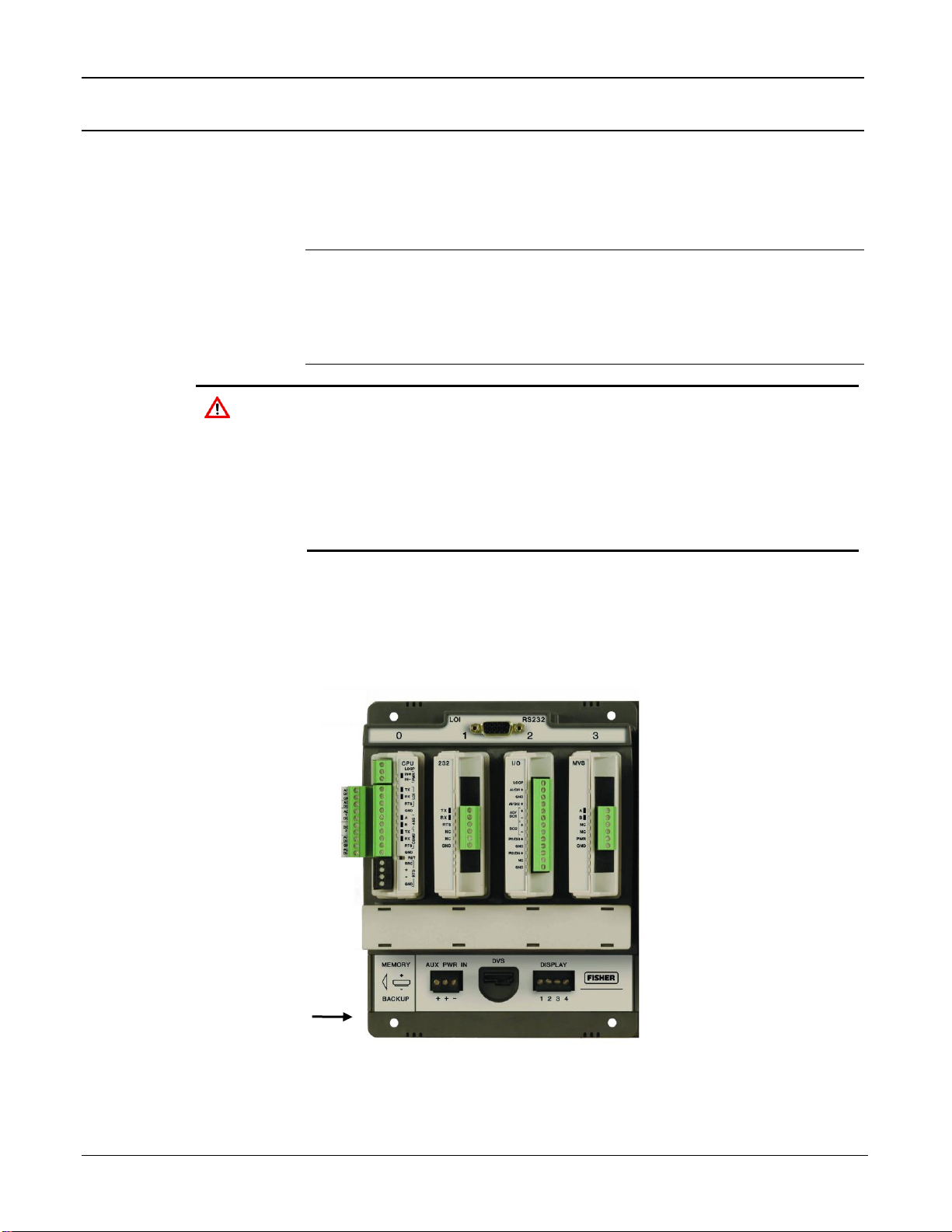
FloBoss 107 Flow Manager Instruction Manual
2-12 Installation and Use Revised May-2018
2.3 Memory Backup Battery
A super capacitor (“super-cap”) and a coin type battery work together to
provide backup power for the static RAM and the real-time clock. This
helps to ensure retention of short and longer-term data, configuration, and
operational integrity when the FB107 is not in service or is in storage.
Note: You can replace the battery with a standard coin-type lithium
model CR2032 (DL2032). Shelf-life for the CR2032 coin cell
battery depends on its manufacturer, but is typically at least 7
years for most major manufacturers (Energizer, Duracell, Sanyo,
etc.) under normal conditions.
Caution
To avoid circuit damage when working inside the unit, use
appropriate electrostatic discharge precautions (such as wearing a
grounded wrist strap).
When working on units located in a hazardous area (where explosive
gases may be present), make sure the area is in a non-hazardous
state before performing procedures. Performing these procedures in
a hazardous area could result in personal injury or property damage.
2.3.1 Removing and Installing the Battery
To remove the coin cell battery (CR2032) on the backplane:
1. Remove power from the FB107.
Memory Backup
Figure 2-6. Memory Backup Cap
Page 45

FloBoss 107 Flow Manager Instruction Manual
Revised May-2018 Installation and Use 2-13
2. Slide the Memory Backup cover to the left.
3. Remove the battery by gently prying the battery from its terminals.
4. Replace the battery by placing the battery positive-side up and gently
pressing it into place.
5. Slide the Memory Backup cover back over the battery.
6. Restore power to the FB107.
Note: The super capacitor is not field-replaceable.
2.4 Central Processor Unit (CPU)
The FB107 base unit has four slots. Slot 0 is reserved for the CPU
module. The CPU provides connections to the field wiring and surge and
static discharge protection for the field wiring. Electronics include the
RTD, comms, and power.
The CPU contains the firmware, the three built-in communication ports
and LEDs, a reset (RST) switch, RTD input, and a power LED indicating
system integrity.
The internal super-cap backup battery provides backup of data and the
real-time clock when the main power is not connected.
Page 46

FloBoss 107 Flow Manager Instruction Manual
2-14 Installation and Use Revised May-2018
A
Loop power +
B
Power In +
C
Power In -
D
LOI Tx (Red)
E
LOI Rx (White)
F
LOI RTS
G
Ground (Black)
H
RS-485 A
I
RS-485 B
J
RS-232 Tx
K
RS-232 Rx
L
RS-232 RTS
M
Ground
N
RTD Source
O
RTD +
P
RTD -
Q
RTD Return
R
Loop Output Power
S
Power Input
T
EIA-232 (RS-232) Local LOI Port
U
EIA-485 (RS-485) COM1
V
EIA-232 (RS-232) COM2
W
Reset Switch
X
Resistance Thermal Device (RTD)
Figure 2-7. CPU Module
R
S
T
U
V
W
X
B
C
D
E
F G A H I
J
K
L
M
N
O P Q
Page 47

FloBoss 107 Flow Manager Instruction Manual
Revised May-2018 Installation and Use 2-15
2.4.1 Removing the CPU Module
Caution
Failure to exercise proper electrostatic discharge precautions (such
as wearing a grounded wrist strap) may reset the processor or
damage electronic components, resulting in interrupted operations.
When working on units located in a hazardous area (where explosive
gases may be present), make sure the area is in a non-hazardous
state before performing procedures. Performing these procedures in
a hazardous area could result in personal injury or property damage.
To remove the CPU module:
1. Perform the backup procedure described in Preserving Configuration
and Log Data in Chapter 7, Troubleshooting.
2. Remove power from the FB107.
3. Remove all wiring from the CPU.
4. Place your fingers on the ridged edges on both sides of the CPU
module and pull gently (see Figure 2-8). The cover should slide
forward and stop, releasing the module lock.
Figure 2-8. Ridged Edges on CPU Module
5. Gently rock the module until it releases from the backplane and you
can remove it from the base unit.
Page 48

FloBoss 107 Flow Manager Instruction Manual
2-16 Installation and Use Revised May-2018
2.4.2 Installing the CPU Module
Caution
Failure to exercise proper electrostatic discharge precautions (such
as wearing a grounded wrist strap) may reset the processor or
damage electronic components, resulting in interrupted operations.
When working on units located in a hazardous area (where explosive
gases may be present), make sure the area is in a non-hazardous
state before performing+ procedures. Performing these procedures
in a hazardous area could result in personal injury or property
damage.
To install the CPU module:
1. Remove power from the FB107.
2. Slide the CPU module into slot 0.
Note: The CPU wire terminals face to the left. A tab on the module
case prevents you from installing the module incorrectly.
3. Press the CPU firmly into the slot. The connectors at the back of the
CPU module fit securely into the connectors on the backplane.
4. Wire the CPU (see Figure 2-7).
5. Review Restarting and Reconfiguring the FB107 in Chapter 7,
Troubleshooting.
6. Return power to the FB107.
2.4.3 Resetting the CPU
The FB107 CPU provides a reset (RST) switch (see Figure 2-7). Use it to
restore the FB107 to factory default settings. See Resetting the FB107 in
Chapter 7, Troubleshooting for specific instructions.
2.5 License Keys
License keys with valid license codes grant access to applications or
allow optional firmware functionality to execute. A license key may also
be required before you can run the application. Examples of licensed
applications may include flow or properties calculations and various user
programs. You can configure these applications using ROCLINK 800’s
License Key Administrator function (Utilities > License Key
Administrator).
If you remove a license key after enabling an application, the firmware
disables the task from running. This prevents unauthorized execution of
protected applications.
Page 49

FloBoss 107 Flow Manager Instruction Manual
Revised May-2018 Installation and Use 2-17
Note: You must remove power and re-power the FB107 when you
install or remove a license key.
2.6 Startup and Operation
Before starting the FB107, perform the following checks to ensure the
unit is properly installed.
▪ Check the field wiring for proper installation.
▪ Make sure the input power has the correct polarity.
▪ Make sure that the CPU, I/O, MVS, application, and communication
modules are seated in the backplane.
▪ Make sure the input power is fused at the power source. Plug the
input power either into the AUX PWR IN on the base unit or into the
connector labeled PWR+ / PWR on the CPU module.
2.6.1 Startup
Before you apply power to the FB107, assess the power requirements
(including the base unit, expansion rack, and any installed modules and
peripheral devices) that comprise the total configuration for your FB107.
Refer to Determining Power Consumption in Chapter 3, Power
Connections.
Apply power to the FB107. The power input PWR+ LED indicator
should light green to indicate that the applied voltage is correct and a
valid operation is active.
After the start-up diagnostics (RAM and other internal checks) complete,
you should be able to log in to the FB107, which indicates the FB107
completed a valid reset sequence. If you cannot log on to the FB107, refer
to Chapter 7, Troubleshooting, for possible causes.
Caution
Check the input power polarity before connecting power to the
FB107. Incorrect polarity can damage the FB107.
When working on units located in a hazardous area (where explosive
gases may be present), make sure the area is in a non-hazardous
state before performing procedures. Performing these procedures in
a hazardous area could result in personal injury or property damage.
2.6.2 Operation
Once startup is successful, it is necessary to configure the FB107 to meet
the requirements of the application. Refer to the ROCLINK 800
Configuration Software User Manual (for FloBoss 107) (Form A6217)
for procedures on configuring the FB107 and calibrating its I/O. Once
you configure and calibrate the FB107, you can place it in operation.
Page 50

FloBoss 107 Flow Manager Instruction Manual
2-18 Installation and Use Revised May-2018
During operation, you can monitor the FB107 to view or retrieve current
and historical data either locally or remotely. You accomplish local
monitoring using ROCLINK 800 on a PC connected through the LOI
port. You accomplish remote monitoring by using ROCLINK 800
connected through the COM1 through COM3 ports.
The FB107 has a number of software settings (parameters) which you
must configure (using ROCLINK 800 on a PC) before the unit is
calibrated and placed into operation. Normally, the PC is connected to the
LOI port of the FB107 to transfer configuration data into the FB107,
although you can perform much of the configuration off-line and later
load it into the FB107.
The FB107 firmware provides default values for all parameters. If the
default values are acceptable for your application, leave the device as it
was delivered from the factory.
Page 51

FloBoss 107 Flow Manager Instruction Manual
Revised May-2018 Power Connections 3-1
Chapter 3 – Power Connections
In This Chapter
3.1 Power Input Descriptions ................................................................... 3-1
3.2 Determining Power Consumption....................................................... 3-3
3.2.1 Summary ............................................................................... 3-6
3.3 Wiring Connections ............................................................................ 3-6
3.4 Wiring Power to the CPU Module....................................................... 3-7
This chapter describes wiring with FB107 with power from a dc voltage
source.
3.1 Power Input Descriptions
The FB107’s power terminals (either through the AUX PWR IN
connection on the base unit or through the power connections on the CPU
module) convert external input power to the voltage levels the FB107’s
electronics require.
A
AUX PWR IN
B
Power Input
C
CPU Module
Figure 3-1. FB107 Power Inputs
Caution
When installing units in a hazardous area, make sure all installation
components selected are labeled for use in such areas. Installation
and maintenance must be performed only when the area is known to
be non-hazardous. Installation in a hazardous area could result in
personal injury or property damage.
B
A
C
Page 52

FloBoss 107 Flow Manager Instruction Manual
3-2 Power Connections Revised May-2018
Take care to route power away from hazardous areas, sensitive
monitoring devices, and radio equipment. Local and company codes
generally provide guidelines for power installations. Rigorously follow all
local and National Electrical Code (NEC) requirements for power
installations.
Power
Requirements
A dc voltage source is the typical source of primary power for FB107
installations. The FB107 accepts input voltages from 8.0 volts to 30.0
volts either at the AUX PWR IN connection on the base unit or at the
PWR (IN+ / IN) terminals on the CPU. The AUX PWR IN terminal
block accepts wires from size 12 to 22 AWG.
The power consumption of an FB107 and the attached expansion racks
determines the current requirements for the external power supply.
The CPU module’s power input has a removable terminal block for
wiring and servicing. The terminal blocks can accept size 16 to 24 AWG
(American Wire Gauge).
Note: Isolation occurs between the CPU and the field logic.
Using ROCLINK 800, you can configure the I/O on the CPU module to
set the loop output power to 10 volts dc or 24 volts dc:
▪ The 24-volt setting of the loop output power is used to power
devices that require 24 volts dc to ground, allowing the external
device to send the FB107 a 4 to 20 mA signal based on pressure,
temperature, level, and such.
▪ The 10-volt setting of the loop output power is intended for low
power transmitters. The loop current is designed to deliver 80 mA
to power two field devices that connect back to the two analog
inputs.
Note: The CPU I/O assembly uses the CPU’s loop power output and
ground connections.
The I/O module only supports 24 volts dc loop output power. When 10
volts is selected, the loop output power will be 10V+ depending on input
power supply
Note: If the input voltage is greater than the 10-volt loop, then the loop
voltage equals the input voltage. For example, if the PWR IN is
14 volts dc and you select a 10-volt loop, the loop output equals
14 volts dc.
You can use current analog inputs of 4 to 20 mA when the 250-ohm
resistor is selected in the AI configuration using ROCLINK 800.
Page 53

FloBoss 107 Flow Manager Instruction Manual
Revised May-2018 Power Connections 3-3
Table 3-1. Input Terminal Block Connections
Terminal Blocks
Definition
Volts DC
PWR (IN + / IN –)
Accepts up to 28 Volts dc nominal from an AC/DC converter
or other 28 volts dc supply.
8 to 30 Volts dc
LOOP and GND
Supplies 10 Volts dc or 24 Volts dc source voltage to
external field devices. Current limit protected.
10 Volts dc or 24 Volts
dc
3.2 Determining Power Consumption
Use Table 3-1 to identify and Table 3-2 to calculate the power
requirements for the configuration of your FB107. If the power input is
not sufficient, you must either provide an alternative power supply for
external devices or reduce power demands. See Table 3-3 for an example
of a completed power consumption worksheet.
Note: The worksheet shown in Table 3-2 is available to registered users
as a Microsoft Excel® spreadsheet on the Remote Automation
Solutions SupportNet™ website. Access
www.EmersonProcess.com/Remote/Support/Support_login.html
and look for FB107_Power_Wksht.xls under Downloads.
Download the spreadsheet to calculate—and manage—variations
on your particular power requirements.
Table 3-2. Estimated Power Consumption by Module
Valid Slots
Module Description
Base Idle
(No Load)
Max Active
(Full Load)
Loading
Factor
Module Power2
in mW
0
CPU Non-Isolated
360
360
100%
360
0
CPU Non-Isolated with I/O
396
476
100%
476
0
CPU Isolated
540
540
100%
540
0
CPU Isolated with I/O
576
656
100%
656
1,2
RS-232 Module
21
50
100%
50
1,2
RS-485 Module
27
35
100%
35
1,2
Enhanced Comm Module
450
610
100%
610
1,2
Dial-up Modem Module
1 2 100%
2
1 through 71
6-Point I/O Module
180
260
100%
260
1 through 71
DO Relay Module
180
270
100%
270
1 through 71
8-Point AI/DI Module
145
3900
100%
3900
1 through 71
6-Channel AO/DO Module
320
2900
100%
2900
1 through 71
3-Channel RTD Module
220
225
100%
225
1 through 7
HART Module
210
410
100%
410
1 through 7
MVS Interface Module
150
200
100%
200
1 through 7
APP 485 Application Module
150
160
100%
160
1 through 7
IEC 62591 Module
1080
1440
100%
1440
1,2
Network Radio Module
288
720
100%
720
Page 54

FloBoss 107 Flow Manager Instruction Manual
3-4 Power Connections Revised May-2018
1
Valid for slot 7 only if a Comm module is installed in slot 1
2
Represents Base (Loop loading x Loading Factor)
Table 3-3. Power Consumption Worksheet
Power1
Total Power
System Power (mW)
Field Power (mW)
Voltage2
Input Voltage (V dc)
Field Voltage (V dc)
Total Voltage
Current3
System Current mA
Communications mA (Average)
Total Current mA on Power System
Miscellaneous4
Battery Voltage
Battery Capacity Amp/Hour
Depth of Discharge
Available Hours
Days of Autonomy
1
System Power represents the base or idle load; Field Power represents the active load; Total
Power is the sum of the two values, representing the maximum of all modules at all times.
2
Voltage indicates 12 V dc or 24 V dc Power Input module.
3
Current (calculated as Total Power / Input Voltage) represents the system current as well as any
added external current through communications devices.
4
Miscellaneous identifies several components:
▪ Battery Voltage: a given value from the manufacturer
▪ Battery Capacity Amp/Hr: a given value from the manufacturer
▪ Depth of Discharge: A percentage of battery power used.
▪ Available Hours: The number of hours the unit can be powered without external charging of the
power system.
▪ Days of Autonomy: the number of days the device can perform without external power, given the
estimated power requirements.
Page 55

FloBoss 107 Flow Manager Instruction Manual
Revised May-2018 Power Connections 3-5
For example, let’s suppose the following module configuration for an
eight-slot FB107:
Valid
Slots Module Description
Base Idle
(No Load)
Max Active
(Full Load)
Add’l
Load
Loading
Factor
Module
Power
in mW
0
CPU Isolated with I/O
576
656
80
100%
656
1
Enhanced Comm Module
450
610
160
20%
482
2
8-Point AI/DI Module
145
3900
3755
100%
3900
3
6-Point I/O Module
180
260
80
100%
260
4
6-Point I/O Module
180
260
80
100%
260
5
DO Relay Module
180
270
90
100%
270
6
HART Module
210
410
200
10%
230
7
MVS Interface Module
150
200
50
100%
200
Totals
2071
6566
6258
The resulting worksheet would resemble:
Power
Total Power
6258
System Power (mW)
2071 Field Power (mW)
4187
Voltage
Input Voltage (V dc)
12.0 Field Voltage (V dc)
24
Current
System Current mA
521.5
Communications mA (Average)
300.0
Total Current mA on Power System
821.5
Miscellaneous
Battery Voltage
12.0
Battery Capacity Amp/Hour
72.0 Depth of Discharge
20%
Available Hours
70.1 Days of Autonomy
2.92
A
Calculated by adding base idle (no load) values for all chosen modules
B
Calculated by adding System Power and Field Power values (2071 + 4187)
C
Calculated by subtracting System Power value from Total Power value (6258 – 2071)
D
Calculated by dividing Total Power by Input Voltage (6258/12)
E
Entered value from manufacturer’s specifications
F
Calculated by adding System Current and Communications Current (521.5 + 300)
G
Value provided by battery manufacturer
A
C
D
F B G
E
Page 56

FloBoss 107 Flow Manager Instruction Manual
3-6 Power Connections Revised May-2018
3.2.1 Summary
Using the worksheet, you can determine the day-to-day power
requirements for your intended system as well as how much battery
power you may require to maintain your system in the absence of external
power. By downloading the Excel spreadsheet from SupportNet, you can
then adjust your expectations and requirements to meet your FB107
power needs.
3.3 Wiring Connections
This section describes how to connect the FB107 to power, I/O devices,
and communication devices. Use the recommendations and procedures
described in this section to avoid damage to equipment.
Note: Check the input power polarity before you apply the power.
The external connections or field terminals are located on the CPU or
optional modules. The terminal block accepts wires up to size 16 to 24
AWG.
Caution
Always turn off the power to the FB107 before you attempt any type of
wiring. Wiring powered equipment could result in personal injury or
property damage.
To avoid circuit damage when working inside the unit, use appropriate
electrostatic discharge precautions, such as wearing a grounded wrist
strap.
I/O wiring requirements are site- and application-dependent. Local, state,
or NEC requirements determine the I/O wiring installation methods.
Direct burial cable, conduit and cable, or overhead cables are options for
I/O wiring installations.
Caution
Failure to exercise proper electrostatic discharge precautions, such as
wearing a grounded wrist strap may reset the processor or damage
electronic components, resulting in interrupted operations.
To connect the wire to the removable block compression terminals:
1. Strip ¼ inch of insulation from the wire.
2. Insert the bare end into the clamp beneath the termination screw.
3. Tighten the screw, taking care not to over-torque it.
Expose a minimum of bare wire to prevent short circuits. Allow some
slack when making connections to prevent strain.
Note: Twisted-pair cable is recommended for I/O signal wiring.
Page 57

FloBoss 107 Flow Manager Instruction Manual
Revised May-2018 Power Connections 3-7
3.4 Wiring Power to the CPU Module
Typically, you would use the AUX PWR IN connection on the FB107
base unit to power the FB107. Alternately, you can wire power directly
into the CPU module.
A
Loop Power + Output
B
Power In +
C
Power In –
Figure 3-2. Power Wiring, CPU Module
The CPU module connectors use compression terminals. The input power
termination (IN+ / IN) uses a removable connector and accommodates
wiring size 16 to 24 AWG. Refer to Section 3.3, Wiring Connections.
The FB107 accepts input voltages from 8.0 to 30.0 volts at the PWR IN+
/ IN input power terminals
Labels on the CPU (see Figure 3-2) identify the IN+ terminal for positive
power connection (8.0 to 30.0 volts power) and the IN terminal for
negative power connection (Battery Common).
Note: Follow good wiring practices when sizing, routing, and
connecting power wiring. All wiring must conform to state, local,
and NEC codes.
A B C
Page 58

FloBoss 107 Flow Manager Instruction Manual
3-8 Power Connections Revised May-2018
[This page is intentionally left blank.]
Page 59

FloBoss 107 Flow Manager Instruction Manual
Revised May-2018 Inputs and Outputs 4-1
Chapter 4 – Inputs and Outputs
In This Chapter
4.1 I/O Description .................................................................................... 4-1
4.2 Installing a Module ............................................................................. 4-5
4.3 Removing a Module ........................................................................... 4-6
4.4 Wiring a Module.................................................................................. 4-7
4.5 Selecting the Type of I/O .................................................................... 4-7
4.6 Analog Inputs (AI) ............................................................................... 4-9
4.6.1 Wiring the Analog Inputs ....................................................... 4-9
4.7 8-Point Analog Input/Digital Input (AI/DI) Module ............................ 4-11
4.7.1 Wiring the 8-Point AI/DI ....................................................... 4-11
4.8 Analog Outputs (AO) ........................................................................ 4-13
4.8.1 Wiring the Analog Outputs .................................................. 4-13
4.9 Discrete Inputs (DI) .......................................................................... 4-14
4.9.1 Wiring the Discrete Inputs ................................................... 4-15
4.10 Discrete Outputs (DO) ...................................................................... 4-15
4.10.1 Wiring the Discrete Outputs ................................................ 4-16
4.11 Discrete Outputs Relay (DOR) Module ............................................ 4-17
4.11.1 Wiring the Discrete Output Relays ...................................... 4-18
4.12 Pulse Inputs (PI) ............................................................................... 4-19
4.12.1 Wiring the Pulse Inputs ....................................................... 4-19
4.13 Application (APP 485) Module ......................................................... 4-20
4.13.1 Wiring the Application Module ............................................. 4-20
4.14 Resistance Temperature Detector (RTD) Input ............................... 4-22
4.14.1 Wiring the RTD Input ........................................................... 4-22
4.15 6-Point AO/DO Module ..................................................................... 4-23
4.15.1 Wiring the 6-Point AO/DO Module ...................................... 4-24
4.16 HART® Module ................................................................................. 4-24
4.16.1 Wiring the HART Module ..................................................... 4-25
4.17 Resistance Temperature Detector (RTD) Module ............................ 4-26
4.17.1 Wiring the RTD Module ....................................................... 4-26
4.18 IEC 62591 Module ............................................................................ 4-27
4.18.1 Wiring the IEC 62591 Module ............................................. 4-28
4.19 Related Product Data Sheets ........................................................... 4-28
This chapter describes the input/output (I/O) termination points available
on the CPU module’s optional I/O assembly and the I/O modules. I/O
points provide additional inputs and outputs for implementing expanded
monitoring and control applications. This chapter also describes the
resistance thermal device (RTD) input on the CPU.
Note: You can place an I/O module in any slot (1 through 7) in the
FB107. When you install a non-I/O module in slot 1, you can
install an I/O module in slot 7 of the expansion rack.
4.1 I/O Description
The I/O options use the microprocessor to monitor, control, and acquire
data from external devices connected to the I/O channels. The I/O
Page 60

FloBoss 107 Flow Manager Instruction Manual
4-2 Inputs and Outputs Revised May-2018
channels have a removable plug-in terminal block for field wiring. You
can order the expanded 6-point I/O as an:
▪ I/O assembly that mounts directly on the CPU module.
▪ I/O modules that mount in the I/O slots.
Both ways provide configuration terminations for six points of expansion
I/O and both provide the same selections for I/O.
The six points of I/O consist of:
▪ Two analog inputs (AI) or discrete inputs (DI).
▪ One analog output (AO) or discrete output (DO).
▪ One discrete output (DO).
▪ Two pulse inputs (PI) or discrete inputs (DI).
Using ROCLINK 800, you can select and configure five of the six I/O
points. Use ROCLINK 800’s I/O Setup screen to select the inputs and
outputs.
You can add an expansion rack to the FB107 to increase I/O by four slots
for a total of six slots of I/O. The FB107 can support up to six I/O
modules.
You can install I/O modules in slots 1 through 3 on the FB107 base unit
and in slots 4 through 6 on the expansion rack.
I/O support for the FB107 includes:
▪ Analog inputs (AI) that provide the ability to monitor various analog
field values.
▪ Discrete inputs (DI) and pulse inputs (PI) that provide the ability to
monitor various discrete and pulse input field values.
▪ Analog outputs (AO) and discrete outputs (DO) that provide the
ability to manage various control devices.
▪ RTD input provides the ability to monitor various analog temperature
field values.
Each module rests in a module slot at the front of the FB107 base unit or
expansion rack. The CPU I/O assembly attaches to the CPU module.
The I/O modules acquire power from the backplane. Each module has a
dc/dc converter that provides logic, control, and field power as required.
The CPU I/O assembly acquires logic, control, and field power from the
CPU module.
The FB107 has eliminated the need for fuses on the loop output and
analog output through the extensive use of current-limited short-circuit
protection.
Figure 4-1 and Table 4-1 detail the I/O terminations on the I/O module.
Figure 4-2 and Table 4-2 detail the I/O terminations on the CPU
module’s optional I/O assembly.
Page 61

FloBoss 107 Flow Manager Instruction Manual
Revised May-2018 Inputs and Outputs 4-3
Note: There are slight differences in the termination positions.
A
Loop Output Power
B
AI1+/DI1+
C
GND – (Common)
D
AI2+/DI2+
E
AO+/DO1+
F
AO–/DO1–
G
DO2+
H
DO2–
I
PI1+/DI3+
J
GND – (Common)
K
PI2+/DI4+
L
NC (No Connection)
M
GND – (Common)
Figure 4-1. I/O Module
Table 4-1. I/O Terminations on the I/O Modules
Termination
Number
I/O Type
13
Loop Output Power
12
AI1+/DI1+
11
GND – (Common)
10
AI2+/DI2+
9
AO+/DO1+
8
AO-/DO1
A
B
C
D
E
F
G
H
I
J
K L M
Page 62

FloBoss 107 Flow Manager Instruction Manual
4-4 Inputs and Outputs Revised May-2018
Termination
Number
I/O Type
7
DO2+
6
DO2
5
PI1+/DI3+
4
GND – (Common)
3
PI2+/DI4+
2
NC (No Connection)
1
GND – (Common)
A
AI1+/DI1+
B
GND – (Common)
C
AI2+/DI2+
D
AO+/DO1+
E
AO–/DO1–
F
DO2+
G
DO2–
H
PI1+/DI3+
I
GND – (Common)
J
PI2+/DI4+
Figure 4-2. CPU Module’s Optional I/O Assembly
Caution
The default value of D and E (see
Figure 4-2
) is AO. If wired as a DO,
be sure you configure this input value in ROCLINK 800 as a DO before
connecting wiring to an end device. This prevents damage to the
module.
A
B
C
D
E
F
G
H
I
J
Page 63

FloBoss 107 Flow Manager Instruction Manual
Revised May-2018 Inputs and Outputs 4-5
Table 4-2. I/O Terminations on the CPU Module’s Optional I/O Assembly
Termination
Number
I/O Type
10
AI1+/DI1+
9
GND – (Common)
8
AI2+/DI2+
7
AO+/DO1+
6
AO-/DO1
5
DO2+
4
DO2
3
PI1+/DI3+
2
GND – (Common)
1
PI2+/DI4+
4.2 Installing a Module
All I/O modules for the FB107 are designed for ease of installation and
removal. They contain no user-serviceable components.
Note: A tab on the module’s case prevents you from installing the
module incorrectly.
To install an I/O module in either the base unit or the expansion rack:
1. Remove power from the FB107.
2. Remove the wire channel cover.
3. Perform one of the following:
▪ If there is a module currently in the slot, remove that module.
Refer to Section 4.3, Removing a Module.
▪ If the slot is currently empty, remove the slot cover.
4. Ensure that the module cover (the piece with ridged edges) is closed
against the body of the module. This enables the locking mechanism
to secure the module in the slot.
5. Insert the module in the slot on the base unit or expansion rack.
Ensure that the module is installed facing the correct direction. Gently
slide the module into place until it contacts properly with the
connectors on the backplane.
Note: If the module stops and does not go any further, do not force
the module. Remove the module and see if the pins are bent. If
the pins are bent, gently straighten the pins and re-insert the
module. The back of the module must connect fully with the
connectors on the backplane.
Page 64

FloBoss 107 Flow Manager Instruction Manual
4-6 Inputs and Outputs Revised May-2018
6. Wire the I/O module. Refer to Section 4.4, Wiring a Module.
7. Replace the wire channel cover.
Caution
Never connect the sheath surrounding shielded wiring to a signal
ground terminal or to the common terminal of an I/O module or CPU I/O
assembly. Doing so makes the I/O module susceptible to static
discharge, which can permanently damage the I/O. Connect the shielded
wiring sheath only to a suitable earth ground.
8. Return power to the FB107.
9. Connect to ROCLINK 800 and log in.
10. Configure the I/O point.
Note: You must perform a power re-start to enable the ROCLINK 800
software to identify the module.
4.3 Removing a Module
To remove an I/O module:
1. Remove power from the FB107.
2. Remove the wiring (or the removable terminal blocks) from the
module.
3. Place your fingers on the ridged edges on both sides of the module
and pull out gently (see Figure 4-3). The cover should slide forward
and stop, releasing the module lock.
Figure 4-3. Ridged Edges on Modules
4. Gently rock the module until it releases from the backplane and you
can remove it from the base unit or expansion rack.
Page 65

FloBoss 107 Flow Manager Instruction Manual
Revised May-2018 Inputs and Outputs 4-7
Note: Once you remove a module, always be sure to replace its cover.
This protects the module slot from dust and prevents damage to
the cover’s locking mechanism.
4.4 Wiring a Module
I/O wiring requirements are site and application dependent. Local, state,
or NEC requirements determine the I/O wiring installation methods.
Direct burial cable, conduit and cable, or overhead cables are options for
I/O wiring installations.
All I/O modules, the CPU I/O assembly, and RTD inputs have terminal
blocks for convenient wiring and servicing. The terminal blocks
accommodate size 16 to 24 AWG.
Caution
Failure to exercise proper electrostatic discharge precautions, such as
wearing a grounded wrist strap may reset the processor or damage
electronic components, resulting in interrupted operations.
To connect the wire to the removable block compression terminals:
1. Strip ¼ inch of insulation from the wire.
2. Insert the bare end into the clamp beneath the termination screw.
3. Tighten the screw, taking care not to over-torque it.
Expose a minimum of bare wire to prevent short circuits. Allow some
slack when making connections to prevent strain.
Note: Twisted-pair cable is recommended for I/O signal wiring.
4.5 Selecting the Type of I/O
Caution
Configure all AO/DO points in ROCLINK before connecting any wiring.
Failure to do so may result in physical damage to the I/O board.
Using ROCLINK 800, you select the type of input or output.
1. Log on to the FB107 using ROCLINK 800.
Note: ROCLINK 800 provides an enhanced graphical user interface
(GUI) for the FB107. This interface displays an image of the
FB107 above a tabbed screen (see Figures 4-4 and 4-5). You
select the FB107 module and then use the tabbed screen to
configure the components.
2. Click the I/O module. The display immediately under the FB107
image changes to reflect your selection.
Page 66

FloBoss 107 Flow Manager Instruction Manual
4-8 Inputs and Outputs Revised May-2018
Note: Figure 4-5 shows the default values for an I/O module.
Figure 4-4. FloBoss 107 ROCLINK 800 User Interface
3. Click the I/O Setup tab.
Figure 4-5. I/O Setup
4. Select the types of I/O to use.
Page 67

FloBoss 107 Flow Manager Instruction Manual
Revised May-2018 Inputs and Outputs 4-9
5. If you select analog inputs (AI), select the 250 Ohm Resistor
Installed option if you want the analog input in the current loop
mode.
6. Click Apply.
Note: Make sure you select the I/O types before you configure the I/O
using ROCLINK 800.
4.6 Analog Inputs (AI)
Analog inputs (AI) monitor current loop and voltage input devices. The
12-bit A/D signal input range is 0 to 100% EU value (where 0% EU is
643 counts and 100% EU is 3220 counts). You configure the analog
inputs using ROCLINK 800 software.
Notes:
▪ The type E diagnostic analog inputs (logic voltage, battery voltage,
charge in, system milliamps, and battery temperature) are not
designed to be configured or wired.
▪ Select AI as the I/O Type for the selectable analog input/discrete input
when you configure it for use as an analog input. Refer to Figure 4-5.
The analog input (AI) channels are scalable, but typically measure either:
▪ 4 to 20 mA analog signal.
▪ 1 to 5 volts dc signal.
If required, you can calibrate the low end of the analog signal to zero.
The terminal blocks can accommodate size 16 to 24 AWG.
4.6.1 Wiring the Analog Inputs
The terminals for connecting the analog input wiring are shown in
Figures 4-6 and 4-7.
The + terminal is the positive signal input and the GND terminal is the
signal common (). These terminals accept a voltage signal in the 0 to 5
volt range. The GND terminal is internally connected to common so the
analog input channels function as single-ended inputs only. Use the
LOOP terminal to power external devices.
Wiring the Loop
Power Outputs
Using ROCLINK 800, you can configure the CPU module’s optional
I/O assembly to set the loop output power to 10 volts dc or 24 volts dc.
Note: If the input voltage is greater than the 10-volt loop, then the loop
voltage equals the input voltage. For example, if the PWR IN is
14 volts dc and you select a 10-volt loop, the loop output equals
14 volts dc.
Page 68

FloBoss 107 Flow Manager Instruction Manual
4-10 Inputs and Outputs Revised May-2018
The I/O module only supports 24 volts dc loop output power. The CPU
module’s I/O assembly uses the CPU’s loop power output and ground
connections.
The intent of the loop output power is to power devices (such as
Rosemount transmitters) that require 24 volts dc to ground and then send
the FB107 a 4 to 20 mA signal based on pressure, temperature, level and
such.
The 10-volt loop output power is intended for low power transmitters that
send a 1 to 5 volts dc rather than a 4 to 20 mA signal.
The loop current is designed to deliver 80 mA to power two field devices
that connect back to the two analog inputs.
EXTERNALLY
POWEREDPOWER
EXTERNAL
DEVICE
ANALOG
-
-
+
DISCRETE DEVICE
EXTERNALLY POWERED
CONTACT-CLOSURE DEVICE
DISCRETE DEVICE
EXTERNALLY POWERED
OPEN COLLECTOR DEVICE
OR
OPEN DRAIN TYPE
+
Figure 4-6. Loop Output Power for the CPU Module’s Optional I/O Assembly
Page 69

FloBoss 107 Flow Manager Instruction Manual
Revised May-2018 Inputs and Outputs 4-11
INTERNALLY
POWERED
DEVICE
ANALOG
Figure 4-7. Loop Output Power for the I/O Module
4.7 8-Point Analog Input/Digital Input (AI/DI) Module
The 8-point analog input/digital input (AI/DI) module provides eight
user-selectable analog or digital inputs. The Analog inputs (AI) monitor
current loop and voltage input devices. The 12-bit A/D signal input range
is 0 to 100% EU value (where 0% EU is 800 counts and 100% EU is
4000 counts). You configure the analog inputs using ROCLINK 800
software.
The terminal blocks can accommodate size 16 to 24 AWG.
4.7.1 Wiring the 8-Point AI/DI
The terminals for connecting the AI/DI wirings are shown in Figures 4-8
through 4-10.
The + terminal is the positive signal input and the GND terminal is the
signal common (). These terminals accept a voltage signal in the 0 to 5
volt range. The GND terminal is internally connected to common so the
analog input channels function as single-ended inputs only. Use the
LOOP terminal to power external devices.
The I/O module only supports 24 volts dc loop output power. The intent
of the loop output power is to power devices (such as Rosemount
transmitters) that require 24 volts dc to ground and then send the FB107 a
4 to 20 mA signal based on pressure, temperature, and level.
Additionally, each AI channel has an installed 250 Ω resistor to
accommodate a 4 to 20 mA signal. If you have a 1–5 V signal or require a
Page 70

FloBoss 107 Flow Manager Instruction Manual
4-12 Inputs and Outputs Revised May-2018
DI channel, you can use ROCLINK 800 to configure the channel as
necessary.
+
-
OPEN DRAIN TYPE
OR
OPEN COLLECTOR DEVICE
EXTERNALLY POWERED
+
-
CONTACT-CLOSURE DEVICE
EXTERNALLY POWERED
DISCRETE DEVICE
DISCRETE DEVICE
Figure 4-8. DI Wiring
INTERNALLY
POWERED
DEVICE
ANALOG
Figure 4-9. AI Wiring (Internal Power)
Page 71

FloBoss 107 Flow Manager Instruction Manual
Revised May-2018 Inputs and Outputs 4-13
EXTERNALLY
POWERED POWER
EXTERNAL
DEVICE
ANALOG
Figure 4-10. AI Wiring (External Power)
4.8 Analog Outputs (AO)
The analog outputs (AO) provide a 4 to 20 mA current source output for
powering analog loop devices. Analog outputs are analog signals the
FB107 generates to regulate equipment, such as control valves or any
device requiring analog control. The AO includes the power supply
connections. The analog outputs use a 12-bit D/A converter with default
A/D values of 0 and 3250 (0 to 100% EU values).
Note: Select AO as the I/O Type for the selectable analog
output/discrete output when you configure it for use as an analog
output. Refer to Figure 4-5.
4.8.1 Wiring the Analog Outputs
The terminals provided on the CPU module for connecting AO wiring
are:
AO+ Positive
AO Common
Caution
You can induce ground loops by tying commons from various modules
together.
Figure 4-11 shows wiring for the analog output.
Page 72

FloBoss 107 Flow Manager Instruction Manual
4-14 Inputs and Outputs Revised May-2018
INTERNALLY
POWERED
Figure 4-11. Analog Output Wiring (on CPU Module)
4.9 Discrete Inputs (DI)
The discrete input (DI) monitors the status of relays, open collector/open
drain type solid-state switches, and other two-state devices. Discrete
inputs come from relays, switches, and other devices, which generate an
on/off, open/close, or high/low signal.
The DI provides a source voltage for dry relay contacts or for an opencollector solid-state switch.
Each DI channel can be software-configured to function as:
▪ Standard discrete inputs.
▪ Latched discrete inputs.
A latched DI remains in the active state until reset. Other parameters can
invert the field signal and gather statistical information on the number of
transitions and the time accumulated in the on- or off-state.
The DI senses the low voltage (less than 0.5 V dc), which signals the
FB107 electronics that the relay contacts have closed. The opening of the
contacts allows the voltage to rise and the DI signals the FB107
electronics that the relay contacts have opened. An FB107 can read a DI a
maximum of 20 times per second (50 millisecond scan).
When a field device (such as a relay contact or open collector) is
connected across + and GND, the closing of the contacts completes the
circuit This activates current flow that the DI circuitry senses and, in turn,
signals the FB107 electronics indicating that the relay contacts have
closed.
Page 73

FloBoss 107 Flow Manager Instruction Manual
Revised May-2018 Inputs and Outputs 4-15
Note: Select DI as the I/O Type for the selectable pulse inputs/discrete
inputs when you configure it for use as a discrete input. Refer to
Figure 4-5.
4.9.1 Wiring the Discrete Inputs
The terminals provided on the CPU module for connecting the DI wiring
are shown in Figure 4-12.
The + terminal is the positive signal input and the GND terminal is the
signal common (). The discrete input operates by providing a closed
contact across terminals + and GND. Refer to Figure 4-12.
Caution
You can induce ground loops by tying commons from various modules
together.
The discrete input is designed to operate only with non-powered
discrete devices, such as “dry” relay contacts, open collector devices,
or isolated solid state switches. Use of the DI channel with powered
devices may cause improper operation or damage.
OR
OPEN DRAIN TYPE
OR
OPEN COLLECTOR DEVICE
EXTERNALLY POWERED
+
-
CONTACT-CLOSURE DEVICE
EXTERNALLY POWERED
+
-
Figure 4-12. Discrete Input Wiring (on CPU Module)
4.10 Discrete Outputs (DO)
The discrete output (DO) provides two-state outputs to energize solidstate relays and power small electrical loads. You can set a discrete
output to send a pulse to a specified device. Discrete outputs are high and
low outputs used to turn equipment on and off.
The DO circuitry is optically coupled to help isolate the processor board
from the input signal. Refer to Figures 4-13 and 4-14.
Page 74

FloBoss 107 Flow Manager Instruction Manual
4-16 Inputs and Outputs Revised May-2018
DO functions include:
▪ Sustained discrete outputs.
▪ Momentary discrete outputs.
▪ Toggled output.
▪ Time duration output.
The discrete output channel is a normally-open, FET switch. The discrete
output is a solid-state switch enabled by individual signals from the
processor I/O lines and capable of handling 50 Volts dc at 0.2 A
maximum.
You configure the DO so that after a reset the DO retains the last value or
switches off. When a request is made to change the state of a DO, the
request is immediately sent to the DO. There is no scan time associated
with a change of DO.
If the DO is in momentary or toggle mode, you can enter a minimum
time-on of 50 milliseconds (.05 seconds).
Notes:
▪ Select DO as the I/O Type for the selectable analog output/discrete
output when you configure it for use as a discrete output. Refer to
Figure 4-5.
▪ When using the discrete output to drive an inductive load (such as a
relay coil), place a suppression diode across the load. This protects the
DO from the reverse Electro-Motive Force (EMF) spike generated
when the inductive load is switched off.
4.10.1 Wiring the Discrete Outputs
The terminals for connecting the DO wiring on the CPU module are
shown in Figures 4-13 and 4-14. The “+” terminal is the high side of the
switch and the “–” terminal is the low side.
Caution
You can induce ground loops by tying commons from various modules
together.
Page 75

FloBoss 107 Flow Manager Instruction Manual
Revised May-2018 Inputs and Outputs 4-17
SWITCHED
DEVICESUPPLY
POWER
LOW SIDE SWITCH
Figure 4-13. Discrete Output Wiring - Low Side Switch (on CPU Module)
SWITCHED
DEVICESUPPLY
POWER
HIGH SIDE SWITCH
Figure 4-14. Discrete Output Wiring - High Side Switch (on CPU Module)
4.11 Discrete Outputs Relay (DOR) Module
The Discrete Output Relay (DOR) module provides control over various
discrete output field devices. An FB107 can support a maximum of six
DOR modules.
DOR modules provide six channels of discrete outputs that may be set to
send a control signal to a specified device. Refer to Figures 4-15 and 4-
Page 76

FloBoss 107 Flow Manager Instruction Manual
4-18 Inputs and Outputs Revised May-2018
16. Using ROCLINK 800 software, you can configure the module as
latched, toggled, momentary, or Timed Duration Outputs (TDO).
The discrete output channel is a normally open contact. The discrete
output is a relay switch enabled by individual signals from the processor
I/O lines and capable of handling 30 Volts dc at 1.0 A maximum.
Additionally, one DOR channel makes the normally closed contact
available to the field.
You configure the DOR so that it either retains the last value on reset or
sets to a user-specified fail-safe value. When a request is made to change
the state of a DO, the request is immediately sent to the DO.
If the DO is in momentary or toggle mode, you can enter a minimum
time-on of 50 milliseconds (.05 seconds).
Note: When using the discrete output to drive an inductive load (such as
a relay coil), place a suppression diode across the load. This
protects the DO from the reverse Electro-Motive Force (EMF)
spike generated when the inductive load is switched off.
4.11.1 Wiring the Discrete Output Relays
The terminals for connecting the DO wiring are shown in Figures 4-15
and 4-16.
Caution
You can induce ground loops by tying commons from various modules
together.
SWITCHED
DEVICESUPPLY
POWER
DO2-DO6
HIGH SIDE SWITCH
Figure 4-15. Discrete Output Relay Module Wiring (High Side Switch)
Page 77

FloBoss 107 Flow Manager Instruction Manual
Revised May-2018 Inputs and Outputs 4-19
SWITCHED
DEVICESUPPLY
POWER
DO2-DO6
LOW SIDE SWITCH
Figure 4-16. Discrete Output Relay Module Wiring (Low Side Switch)
4.12 Pulse Inputs (PI)
Pulse inputs (PI) processes signals from pulse-generating devices and
provide a calculated rate or an accumulated total over a configured
period. The FB107 pulse input circuits are physically the same as the
discrete inputs. The pulse input routes to a pulse accumulator, where the
pulses are counted and accumulated.
The PI is most commonly used to interface to open collector/open drain
type solid-state devices. Use the PI to interface to self-powered devices.
Acceptable PI voltage levels range between 0.5 volts dc (low) and 1.5
volts dc (high).
Caution
The pulse input is designed to operate with non-powered devices,
such as “dry” contacts or isolated solid-state switches. Use of the PI
with externally powered devices may cause improper operation or
damage.
Note: Select PI as the I/O Type for the selectable pulse inputs/discrete
inputs when you configure it for use as a pulse input. Refer to
Figure 4-5.
4.12.1 Wiring the Pulse Inputs
Figure 4-17 shows the terminals on the CPU module for connecting the
PI wiring. The + terminal is a positive source voltage; the GND terminal
is the signal return.
Page 78

FloBoss 107 Flow Manager Instruction Manual
4-20 Inputs and Outputs Revised May-2018
To use the channel as a pulse input, connect the + and GND field wires to
terminals PI1+ or PI2+ and GND.
Caution
You can induce ground loops by tying commons from various modules
together.
INTERNALLY
POWERED
Figure 4-17. Pulse Input Wiring (on CPU Module)
4.13 Application (APP 485) Module
The FB107 Application Module (labeled APP 485) provides a flexible
storage and delivery mechanism for a variety of localized FB107
applications operating in the RS-485 physical environment. These might
include a Gas Chromatograph application module (which would provide a
Modbus interface between the FB107 and an external GC), a level sensor
application, a Coriolis interface, or an ultrasonic interface.
Note: For detailed instructions on using these modules, refer to the
specific documentation for those programs.
4.13.1 Wiring the Application Module
Figure 4-18 shows an application module wired to a single external field
device. Figure 4-19 shows typical wiring to several field devices.
Note: For self-contained applications, field wiring may be unnecessary.
Page 79

FloBoss 107 Flow Manager Instruction Manual
Revised May-2018 Inputs and Outputs 4-21
TERMINATION RESISTOR
120 OHM
FIELD
DEVICE
+
-
EXTERNAL
POWER
USER SUPPLIED
A
B
Figure 4-18. Application Module Wiring to Single Field Device
Note: To provide internal power to a field device, connect the positive
wire to the PWR connection and the negative wire to the GND
connection on the APP485 module. However, this may not be
appropriate in all circumstances. Check with your local Remote
Automation Solutions representative for the solution relevant to
your situation.
FIELD
DEVICE
EXTERNAL
POWER
POWER
EXTERNAL
-
+
DEVICE
FIELD
POWER
EXTERNAL
DEVICE
FIELD
USER SUPPLIED
120 OHM
TERMINATION RESISTOR
+ +
A
B
A
B
A
B
- -
Figure 4-19. Application Module Wiring to Multiple Field Devices
Page 80

FloBoss 107 Flow Manager Instruction Manual
4-22 Inputs and Outputs Revised May-2018
4.14 Resistance Temperature Detector (RTD) Input
The resistance temperature detector (RTD) on the CPU monitors the
temperature signal from an RTD source. The RTD can accommodate
input from a three- or four-wire RTD source. The RTD has a
measurement range of 40 to 400°C (40 to 752°F). The terminals for the
RTD wires are labeled “RTD” on the CPU.
The active element of an RTD probe is a precision, temperaturedependent resistor made from a platinum alloy. The resistor has a
predictable positive temperature coefficient, meaning its resistance
increases with temperature. The RTD input works by supplying a small
consistent current to the RTD probe and measuring the voltage drop
across it. Based on the voltage curve of the RTD, the FB107 firmware
converts the signal to temperature.
The RTD input draws power for the active circuitry from lines on the
backplane.
It may be more convenient to perform calibration before connecting the
field wiring. However, if the field wiring between the FB107 and the
RTD probe is long enough to add a significant resistance, then perform
calibration in a manner that considers this. (According to RTD charts, as
little as 0.23 ohms adds 1°F.)
During operation, the RTD is read every scan period. The value from the
RTD is linearized, and then it is sent to processing as an analog input.
The AI routine converts this value to engineering units, and checks
alarming.
4.14.1 Wiring the RTD Input
Temperature can be input through the resistance temperature device
(RTD) probe and circuitry. An RTD temperature probe mounts directly to
the piping using a thermowell. The RTD measures the flowing
temperature.
Protect RTD wires either by a metal sheath or by conduit connected to a
liquid-tight conduit fitting. A 16-bit A/D converter monitors the RTD
signal. The microprocessor then reads the RTD signal.
The FB107 provides terminations for a four-wire 100-ohm platinum RTD
with an alpha equal to 0.00385//C.
Wiring between the RTD probe and the FB107 must be shielded wire,
with the shield grounded only at one end to prevent ground loops. Ground
loops cause RTD input signal errors.
Caution
You can induce ground loops by tying commons from various modules
together.
Table 4-3 displays the connections at the RTD terminals and 3-wire
jumper requirements. Figure 4-18 shows the RTD sensor wiring.
Page 81

FloBoss 107 Flow Manager Instruction Manual
Revised May-2018 Inputs and Outputs 4-23
Table 4-3. RTD Wiring
Terminal
Wiring Color
Designation
4-Wire RTD
3-Wire RTD
SRC
Red
Signal source current positive input
SRC
SRC
+
Red
+ RTD
+ RTD
+ RTD
White
– RTD
– RTD
– RTD
GND
White
Negative ground return reference
GND
GND jumper to
– RTD
Note: The wire colors for the RTD being used may differ.
A
Red B White
C
Jumper
Figure 4-20. RTD Sensor Wiring (on CPU Module)
4.15 6-Point AO/DO Module
This module provides six single-ended analog outputs or field effect
transistor (FET) switch discrete outputs. You use ROCLINK 800
Configuration software to configure each individual channel.
Warning
The module’s default value is AO. If wired as a DO, be sure you
configure this input value in ROCLINK 800 as a DO before connecting
wiring to an end device. This prevents damage to the module.
RED
RED
WHITE
Jumper
RED
RED
WHITE
WHITE
A A A A B B B
C
Page 82

FloBoss 107 Flow Manager Instruction Manual
4-24 Inputs and Outputs Revised May-2018
All modules have removable terminal blocks for convenient wiring and
servicing. The terminal blocks can accommodate size 16 to 24 American
Wire Gauge (AWG).
4.15.1 Wiring the 6-Point AO/DO Module
Caution
Configure all AO/DO points in ROCLINK before connecting any wiring.
Failure to do so may result in physical damage to the I/O board.
Figures 4-21 through 4-24 show a variety of wiring scenarios.
Figure 4-21. Analog Output 4-20 mA Wiring
Figure 4-22. Analog Output 1-5 V Wiring
DEVICE
POWER
SOURCE
DEVICE
POWER
SOURCE
Figure 4-23. Discrete Output High Side Switch
Wiring
Figure 4-24.. Discrete Output Low Side Switch
Wiring
4.16 HART® Module
The HART® (Highway Addressable Remote Transducer) module allows
the FB107 to communicate with HART devices using the HART
Page 83

FloBoss 107 Flow Manager Instruction Manual
Revised May-2018 Inputs and Outputs 4-25
protocol. The HART module receives signals from and transmits signals
to HART devices.
The HART module has four input/output channels. Software configurable
switches on the module allow each channel to be set as an input or output
channel. A channel set as an input can be configured for use in point-topoint or multi-drop mode. A channel set as an output can be configured
for use in point-point mode only.
In multi-drop mode, as many as five HART devices can be connected (in
parallel) to each channel. A module with all four channels in multi-drop
mode supports a maximum of twenty HART devices.
An FB107 unit equipped with a HART module is considered to be a
HART Host (primary master) interface with a Class 1 Conformance
classification. The HART module can also be configured with ROCLINK
800 Configuration Software for use as a secondary master in redundant
applications.
Note: ROCLINK 800 supports the ability to enable or disable the
termination resistor on the module. This resistor switch defaults to
Enabled; set it to Disabled if the FB107 supports multiple
devices and termination is needed at the end device.
4.16.1 Wiring the HART Module
Figures 4-25 through 4-27 show a variety of wiring scenarios.
Figure 4-25. HART Input Point-to-Point Wiring
Figure 4-26. HART Input Multi-Drop Wiring
Page 84

FloBoss 107 Flow Manager Instruction Manual
4-26 Inputs and Outputs Revised May-2018
Figure 4-27. HART Output Wiring
4.17 Resistance Temperature Detector (RTD) Module
The 3-channel Resistance Temperature Detector (RTD) module enables
the FB107 to monitor various RTD sensors. An FB107 can support up to
six RTD modules.
The module monitors the temperature signal from an RTD within a fixed
range. The module provides three channels for measuring the resistance
of 2-wire, 3-wire, or 4-wire 100-ohm platinum RTD sensors with an
alpha equal to 0.00385 Ω/Ω/C.
Surge protection techniques eliminates the need for fuses, reducing
maintenance needs at remote locations. The module is self-resetting after
a fault clears.
4.17.1 Wiring the RTD Module
Figures 4-28 through 4-30 show example 2-, 3-, and 4-wire wiring
diagrams.
Page 85

FloBoss 107 Flow Manager Instruction Manual
Revised May-2018 Inputs and Outputs 4-27
Figure 4-28. 2-Wire Connection Wiring
Figure 4-29. 3-Wire Connection Wiring
Figure 4-30. 4-Wire Connection Wiring
4.18 IEC 62591 Module
The IEC 62591 module, when installed in a FB107 and wired to a Smart
Wireless Field Link, enables you to communicate with a network of up to
25 WirelessHART devices installed in the field.
Page 86

FloBoss 107 Flow Manager Instruction Manual
4-28 Inputs and Outputs Revised May-2018
Note: Install the module in any available slot other than slot 2. Each
FB107 supports only one IEC 62591 module. For complete
instructions on installing and configuring the module and the
Smart Wireless Field Link, refer to the IEC 62591 Wireless
Interface Instruction Manual (Form 6231).
4.18.1 Wiring the IEC 62591 Module
Figure 4-31 shows the IEC 62591 module wired to a Smart Wireless
Field Link.
Figure 4-31. FB107 IEC 62591 Module Power and Data Wiring to Field
Link
4.19 Additional Technical Information
Refer to the following documents (available at
www.EmersonProcess.com/Remote) for additional and most-current
information on each of the modules discussed in this chapter.
Table 4-4. Additional Technical Information
Name
Form Number
Part Number
FloBoss™ 107 8-Point AI/DI Module
FB107:AIDI
D301464X012
FloBoss™ 107 6-Point Analog Output / Discrete Output Module
FB107:AODO
D301637X012
FloBoss™ 107 Discrete Output Relay Module
FB107:DOR
D301466X012
FloBoss™ 107E Enclosure Options (for Pulse Inputs)
FB107:ENC
D301276X012
FloBoss™ 107 Application Module
FB107:APP
D301665X012
FloBoss™ 107 Resistance Temperature Device (RTD) Module
FB107:RTD
D301638X012
FloBoss™ 107 6-Point Analog Output / Discrete Output Module
FB107:AODO
D301637X012
FloBoss™ 107 HART® Module
FB107:HART
D301639X012
FloBoss™ 107 IEC 62591 Interface
FB107:62591
D301713X012
Page 87

FloBoss 107 Flow Manager Instruction Manual
Revised May-2018 Communications 5-1
Chapter 5 – Communications
In This Chapter
5.1 Communications Overview ................................................................. 5-1
5.2 Installing/Removing a Communication Module .................................. 5-5
5.3 Wiring the Local Operator Interface (LOI) Port .................................. 5-5
5.3.1 Using the LOI ........................................................................ 5-6
5.4 Wiring EIA-485 (RS-485) Communications ........................................ 5-6
5.5 Wiring EIA-232 (RS-232) Communications ........................................ 5-7
5.6 Liquid Crystal Display (LCD) Touchpad ............................................. 5-8
5.7 Enhanced Communication Module (ECM) ......................................... 5-9
5.7.1 Activating the USB Port ....................................................... 5-10
5.8 Dial-Up Modem Module .................................................................... 5-15
5.9 Network Radio Module (NRM) ......................................................... 5-16
5.9.1 Installing the NRM ............................................................... 5-17
5.10 Additional Technical Information ...................................................... 5-17
The FB107 communicates to external devices through its local operator
interface port (LOI), the COM1 EIA-485 (RS-485) port, the COM2 EIA232 (RS-232 port), or optionally on COM3 using a communications
module.
Note: You can place communication modules only in slots 1 and 2 on
the FB107 base unit.
The communication terminals and communication modules provide
communications between the FB107 and a host system or external
devices. The communication modules install directly onto the FB107
backplane and activate the host port when installed.
Warning
Always ensure that the area is non-hazardous before you make any
communication connections (RS-232, RS-485, Ethernet, USB, etc.).
5.1 Communications Overview
The FB107 CPU module provides three built-in communication ports.
You can also install communication modules in slots 1 and 2 in the base
unit.
Page 88

FloBoss 107 Flow Manager Instruction Manual
5-2 Communications Revised May-2018
Figure 5-1. EIA-232 (RS-232) Communication
Module
Figure 5-2. EIA-485 (RS-485) Communication
Module
Page 89

FloBoss 107 Flow Manager Instruction Manual
Revised May-2018 Communications 5-3
A
LOI Local Port EIA-232 (RS-232)
B
COM1 EIA-485 (RS-485)
C
COM2 Default EIA-232 (RS-232)
Figure 5-3. CPU
The FB107 supports up to four communication ports: LOI, COM1,
COM2, and COM3:
▪ Local Operator Interface (RS-232C)
Located on the CPU and labeled LOI (see Figure 5-3), the LOI port
provides asynchronous serial communications, with DB9 connector.
Default LOI values: 19,200 baud rate, 8 data bits, no parity, and 1
stop bit.
Note: The LOI port located on the FB107 base unit (see Figure 1-1)
is factory-wired into the LOI port on the CPU. You can use
either LOI port, but not both.
▪ EIA-485 (RS-485)
Located on the CPU and labeled 485 (see Figure 5-3), the COM1 port
provides asynchronous serial communications, and is the standard for
differential data transmission over distances of up to 1220 m (4000
ft). EIA-485 (RS-485) provides asynchronous serial communications
for multi-drop units on a serial network over long distances using
inexpensive twisted-pair cables.
Default EIA-485 (RS-485) values: 19,200 baud rate, 8 data bits, no
parity, and 1 stop bit.
B C
Page 90

FloBoss 107 Flow Manager Instruction Manual
5-4 Communications Revised May-2018
▪ EIA-232 (RS-232)
Located on the CPU and labeled COM2 (see Figure 5-3), the COM2
port provides the default for serial communications. It is the standard
for single-ended data transmission over distances of up to 15 m (50
ft). EIA-232 (RS-232) provides point-to-point asynchronous serial
communication. EIA-232 (RS-232) communications commonly
provide the physical interface for connecting serial devices, such as
gas chromatographs and radios.
Default EIA-232 (RS-232) values: 19,200 baud rate, 8 data bits, no
parity, and 1 stop bit.
Note: When you install a communication module in slot 2, the
firmware disables the COM2 port on the CPU and redirects it
to the type of module installed in slot 2. Configure COM2
based on the type of communication module installed in slot 2.
▪ Optional communication modules (COM3)
Optional communication modules that use the COM3 port include the
232 (EIA-232 [RS-232]) and 485 (EIA-485 [RS-485]) modules (see
Figures 5-1 and 5-2), the Enhanced Communication module (see
Figure 5-5), and the Dial-Up Modem module (see Figure 5-14).
Note: COM3 activates only when you install a communication
module in slot 1.
Use ROCLINK 800 to configure the modules.
Each communication module uses a separate, single-ended channel from
the other modules. The field interface protects the electronics in the
module.
LEDs display the RX (receive) and TX (transmit) signals for EIA-232
(RS-232) communications.
LEDs display the A (transmit/receive+) and B (transmit/receive ) signals
for EIA-485 (RS-485) communications.
Communication
Protocols
The FB107 has the capability to communicate with other devices using
ROC or Modbus protocols. The firmware can automatically detect the
two protocols (ROC or Modbus) at baud rates of up to 115.2 Kbps.
ROC protocol supports serial communications to local or remote devices,
such as a host computer.
An FB107 can act as a Modbus host or slave device using Remote
Terminal Unit (RTU) or American Standard Code for Information
Interchange (ASCII) modes. This allows you to easily integrate the
FB107 into other systems. Extensions to the Modbus protocol allow the
retrieval of history, event, and alarm data in Electronic Flow Metering
(EFM) Measurement applications.
Note: The LOI port only supports ROC or Modbus slave protocols.
Page 91

FloBoss 107 Flow Manager Instruction Manual
Revised May-2018 Communications 5-5
5.2 Installing/Removing a Communication Module
All FB107 modules are designed for ease of installation and removal.
Refer to Installing a Module, Removing a Module, and Wiring a Module
in Chapter 4, Inputs/Outputs and RTD Inputs, for specific instructions.
You can install communication modules in slots 1 or 2 on the base unit,
which provides power and control signals to those modules.
Slot 1
Installing a communication module in slot 1 on the base unit activates
COM3. COM2 is not affected; it still resides on the CPU. COM3 is
completely independent of any other communication port.
Note: When you install a communication module in slot 1, you can also
install an I/O module in slot 7. This provides a full complement of
6 I/O modules and four communication ports.
Slot 2
Installing a communication module in slot 2 on the base unit
disconnects the CPU module’s COM2 and redirects COM2 to the
newly installed communication module. COM2 always exists.
Note: When you install a communication module in slot 2, the firmware
redirects the CPU module’s communication port (COM2) to the
type of module installed in slot 2. Configure COM2 based on the
type of communication module installed in slot 2.
The hardware decides which signals to use depending on whether a
communication module is installed in slot 2. All other communication
ports are not affected.
5.3 Wiring the Local Operator Interface (LOI) Port
The Local Operator Interface (LOI) port provides a direct, local link
between the FB107 and a PC through an optional Local Operator
Interface Cable using EIA-232 (RS-232C) communications.
Note: You can purchase an LOI cable from your sales representative.
Default values for the LOI port are: 19,200 baud rate, 8 data bits, 1 stop
bit, no parity, 10 millisecond key-on delay, and 10 millisecond key-off
delay. The maximum baud rate is 115.2 Kbps.
The LOI allows you to access the FB107 for configuration and transfer of
stored data. The LOI port is capable of initiating a message in support of
Spontaneous-Report-by-Exception (SRBX) alarming.
The LOI uses the Local Port in ROCLINK 800 software.
The LOI terminal on the CPU module provides wiring access to a built-in
EIA-232 (RS-232C) serial interface. The LOI is software-configurable
with baud rates from 300 to 115.2 Kbps and uses a DB9 connection.
Page 92

FloBoss 107 Flow Manager Instruction Manual
5-6 Communications Revised May-2018
LEDs display the RX (receive) and TX (transmit) signals for EIA-232
(RS-232) communications.
The LOI supports ROC or Modbus slave protocol communications. The
LOI also supports the log-on security feature of the FB107, if you enable
security on the LOI using ROCLINK 800.
Table 5-1 shows the signal routing of the CPU and PC connections. The
FB107’s EIA-232 (RS-232) transmit (TX) connects to the PC’s receive
(RX).
Table 5-1. LOI Port Null-modem Cable Wiring
LOI on
FB107
DB9 on
FB107
PC
TX 2 TX RX 3 RX GND 5 GND
5.3.1 Using the LOI
1. Plug the LOI cable into the LOI connector on the top of the FB107
base unit.
2. Connect the LOI cable to the PC’s COM port.
3. Connect to ROCLINK 800 software and log in.
4. Click the Direct Connect icon.
5. Configure communications for the other built-in and modular
communications, I/O modules, AGA meter parameters, and other
configuration parameters.
5.4 Wiring EIA-485 (RS-485) Communications
The EIA-485 communications provides for RS-485 signals on:
▪ COM1 port located on the CPU (labeled 485).
▪ COM2 located on the CPU when a communications module is
installed in slot 2.
▪ COM3 located on the EIA-485 (RS-485) communications module
installed in slot 1.
Table 5-2 shows termination points for EIA-485 (RS-485)
communications.
The EIA-485 (RS-485) serial communication allows baud rates from 300
to 115.2 Kbps with standard differential data transmissions over distances
of up to 1220 meter (4000 feet). The EIA-485 (RS-485) drivers are
designed for multi-point applications with multiple devices on a single
bus.
Page 93

FloBoss 107 Flow Manager Instruction Manual
Revised May-2018 Communications 5-7
EIA-485 (RS-485) supports the log-on security feature of the FB107 if
you enable security on the communication port using ROCLINK 800.
LEDs display the A (transmit/receive+) and B (transmit/receive ) signals
for EIA-485 (RS-485) communications.
Default values for the EIA-485 (RS-485) communication module are:
19,200 baud rate, 8 data bits, 1 stop bit, no parity, 10 millisecond key-on
delay, and 10 millisecond key-off delay. The maximum baud rate is 115.2
Kbps.
Use twisted-pair cable for wiring. Ensure that you connect terminal A of
FB107 to terminal A of 485 device using RS-485 communications (such
as a gas chromatograph) and terminal B of the FB107 to terminal B of the
device. Should you encounter difficulties establishing a connection, try
reversing the connections.
Note: EIA-485 (RS-485) standards suggest placing a terminating resistor
at the end of the line. The value of each termination resister
should equal the cable impedance (typically 120Ω for twisted
pair).
Table 5-2. EIA-485 (RS-485) Field Wiring Terminals
Label
Definition
A
Transmit / Receive +
B
Transmit / Receive
NC
No connection (comm module only)
NC
No connection (comm module only)
NC
No connection (comm module only)
GND
Ground (common)
5.5 Wiring EIA-232 (RS-232) Communications
The EIA-232 communications meets EIA-232 specifications for singleended, RS-232 asynchronous data transmission over distances of up to 15
m (50 ft). Table 5-3 shows termination points for EIA-232 (RS-232)
communications.
The EIA-232 communications provides for RS-232 signals on:
▪ LOI port located on the CPU.
▪ COM2 located on the CPU.
▪ COM3 located on the EIA-232 (RS-232) communications module
installed in slot 1.
EIA-232 (RS-232) uses point-to-point asynchronous serial
communications and is commonly used to provide the physical interface
for connecting serial devices, such as gas chromatographs and radios to
the FB107. The EIA-232 (RS-232) communication provides ready-tosend (RTS) hand-shaking lines.
Page 94

FloBoss 107 Flow Manager Instruction Manual
5-8 Communications Revised May-2018
The EIA-232 (RS-232) default values are: 19,200 baud rate, 8 bits, 1 stop
bit, no parity, 10 millisecond key-on delay, and 10 millisecond key-off
delay. The maximum baud rate is 115.2 Kbps.
EIA-232 (RS-232) supports the log-on security feature of the FB107 if
you enable the security on the communication port using ROCLINK 800.
The EIA-232 (RS-232) signals include RX, TX, and RTS signal/control
lines. Light-emitting diodes (LEDs) indicate if the FB107 is transmitting
(TX) or receiving (RX).
Table 5-3. EIA-232 (RS-232) Field Wiring Terminals
Label
Definition
TX
Transmit data signals that data is being transmitted from the
comm port
RX
Receive data signals that data is being received at the comm
port
RTS
Ready to Send signals that the port is ready to transmit
NC
No connection (comm module only)
NC
No connection (comm module only)
GND
Ground (common)
5.6 Liquid Crystal Display (LCD) Touchpad
The FB107 supports an external liquid crystal display (or “Touchpad”).
See Figure 5-4.
ALARMKEY ACK
TO ACTIVATE
TOUCH SCREEN
Figure 5-4. Liquid Crystal Display (“Touchpad”)
The FB107 base unit provides connections for the Touchpad (see Figure
5-5). The display functions as an EIA-232 (RS-232) communications
device, supporting ROC or Modbus slave communications protocols.
Page 95

FloBoss 107 Flow Manager Instruction Manual
Revised May-2018 Communications 5-9
The LCD default values are: 19,200 baud rate, 8 data bits, 1 stop bit, no
parity. The maximum baud rate is 57.6 Kbps.
Figure 5-5. Display Connection on Base Unit
Table 5-4. LCD Connections
Label
Function
1
Power Out
2
Ground
3
Transmit (TX) from FB107
4
Receive (RX) to FB107
Note: For further information on installing, configuring, and using the
Touchpad, refer to the FloBoss™ 107 Flow Manager LCD User
Manual (part D301258X012).
5.7 Enhanced Communication Module (ECM)
The Enhanced Communication Module (ECM) provides communications
over a four-session Ethernet port and a Universal Serial Bus (USB) 2.0
port. See Figure 5-6. The FB107 supports up to two ECM modules
installed in slot 1 and 2 of the FB107 base unit
Note: When you install a communication module in slot 2 on the base
unit, the system redirects the communication port (COM2) on the
CPU to the type of module in slot 2.
Caution
Disable sleep mode when using the Enhanced Communications module.
Also, set clock speed to 14 MHz or higher. Use the CPU module’s
Advanced tab to set both these values.
The FB107 supports the Modbus master/slave (ASCII or RTU) and
Modbus TCP communications protocols. Use ROCLINK 800
Configuration software to configure the module.
Each communication module uses a separate channel from the other
modules and has a common (“single-ended”) ground. The field interface
protects the electronics in the module. Filtering reduces the effect of noise
on communication errors.
Page 96

FloBoss 107 Flow Manager Instruction Manual
5-10 Communications Revised May-2018
Figure 5-6. Enhanced Communication Module (ECM)
LED Values
PWR: Blinks for possible error
LINK: Non-blinking connected
ACT: Blinks to indicate activity
Note: If the module hangs during a firmware update, the PWR LED
blinks rapidly. Reload the firmware upgrade.
5.7.1 Activating the USB Port
The ECM includes a USB port that provides local operator interface
(LOI) functions when the configuring laptop may not have a serial (RS-
232) port.
Installing the
USB Driver
You must install a USB driver to activate the USB port in the ECM.
ROCLINK 800 (Version 1.85 and higher) provides this file
(ECM_USB_DRIVER.inf).
Note: Before you begin this installation process, verify that you have
installed Version 1.85 (or higher) of ROCLINK 800 and version
1.30 (or higher) of the FB107 firmware. Also, if your PC already
has this particular USB driver installed, the USB connection is
automatic.
Connect a USB cable from your computer to the USB port on the ECM,
and select Start > Control Panel > Hardware and Sound > Device
Manager. The Device manager screen displays.
Note: If the Found New Hardware Wizard displays, click Cancel.
Page 97

FloBoss 107 Flow Manager Instruction Manual
Revised May-2018 Communications 5-11
Figure 5-7. Device Manager
Select Other devices and double-click ECM USB Device. The ECM
USB Device Properties screen displays.
Figure 5-8. ECM USB Device Properties
Page 98

FloBoss 107 Flow Manager Instruction Manual
5-12 Communications Revised May-2018
Select the Update Driver button.
Figure 5-9. Update Browser Software
Select Browse my computer for driver software.
Figure 5-10. Update Browser Software
Page 99

FloBoss 107 Flow Manager Instruction Manual
Revised May-2018 Communications 5-13
Select the Browse button and navigate to the ROCKLINK800 program
folder. Make sure the Include Subfolders checkbox is selected and click
Next.
Figure 5-11. Windows Security
Windows finds the ECM_USB_DRIVER.inf file, begins the installation
process, and a warning message displays. Select Install this driver
software anyway.
Figure 5-12. Installing Driver Software
Windows copies the driver file into the default System32 folder, and then
displays a confirmation screen.
Page 100

FloBoss 107 Flow Manager Instruction Manual
5-14 Communications Revised May-2018
Figure 5-13. Confirmation Screen
Verifying the
Installation
After you install the ECM, you should verify the installation. To verify
that you have correctly installed the ECM, connect to ROCLINK 800
but do not connect to a device.
Right-click COM1 Device on the displayed tree and select Properties
from the pop-up menu.
Figure 5-14. Pop-up Menu
The Communications Parameters screen displays.
 Loading...