

Remote Automation Solutions FloBoss 104 Flow Manager Safe Use Instructions Manuals & Guides
Page 1

Safe Use Instructions – Emerson FloBoss 104 Flow Manager
Part D301733X012
February 2018
Remote Automation Solutions
Safe Use Instructions:
Emerson FloBoss™ 104 Flow Manager
UK
Safe Use Instructions
DE
Anleitung zur sicheren Verwendung
FR
Consignes de sécurité
PT
Instruções para uso segur o
SC
安全使用说明
IT
Istruzioni per l’uso sicuro
NL
Instructies voor veilig gebruik
SP
Instrucciones para un uso seguro
Page 2

Safe Use Instructions – Emerson FloBoss 104 Flow Manager
Part D301733X012
February 2018
Page 3

Safe Use Instructions – Emerson FloBoss 104 Flow Manager
Part D301733X012
February 2018
Remote Automation Solutions
Emerson FloBoss™ 104 Flow Manager
Figure 1. FloBoss 104 Flow Manager Nameplate
(ATEX Version shown)
Use this safe use instructions (SUI) document with the
FloBoss 103 and FloBoss 104 Flow Manager Instruction
Manual (part D301153X012). For full cautions and
descriptions of installation and troubleshooting
procedures, refer to this manual. If you require training for
this product, contact your local sales office.
The FloBoss 103 Flow Manager with ATEX or IECEx
flameproof approvals may be ordered with optional EIA232 (RS-232) communications, dial-up modem
communications, or Pulse Interface module (PIM).
FloBoss 104 special conditions for Safe Use
▪ Operating Ambient Temperature: 40°C to +75°C.
▪ Ensure that the thermal fluid transfer does not
overheat the equipment to a temperature
corresponding to the spontaneous combustion
temperature of surrounding gas.
Declaration of Conformity
Hereby, Remote Automation Solutions declares that the
FloBoss 103 products are in compliance with the essential
requirements and other relevant provisions of European
Directives 2004/108/EC (EMC), 94/9/EC (ATEX), and
97/23/EC (PED).
DANGER
When installing units in a hazardous area, make sure
all installation components selected are labeled for use
in such areas. Installation and maintenance must be
performed only when the area is known to be nonhazardous. Installation or maintenance in a hazardous
area could result in personal injury or property
damage.
Always turn off the power to the FloBoss before you
attempt any type of wiring. Wiring powered
equipment could result in personal injury or property
damage.
To avoid circuit damage when working inside the unit,
use appropriate electrostatic discharge precautions,
such as wearing a grounded wrist strap.
Do not open covers unless area is known to be nonhazardous.
Connecting the FloBoss 104 to a continuous high
wattage power source without removing the battery
charger module may result in battery overcharging
and failure. See Section 3.5.1, Overcharging Potential
in the FloBoss 103 and 104 Flow Manager Instruction
Manual (part D301153X012).
Page 4

Safe Use Instructions – Emerson FloBoss 104 Flow Manager
Part D301733X012
February 2018
2 www.Emerson.com/RemoteAutomation
Specifications
POWER
External Power Charging Input: 8-28 V dc, reverse
polarity protection.
Input Current: 10-15 mA nominal. 20 mA at 100% duty
cycle (battery charging not included).
ENCLOSURE
Housing and Cap: Die-cast aluminum alloy with iridite
plating and paint. Stainless steel (CF8M) version
available.
ENVIRONMENTAL
Operating Ambient Temperature: -40 to +75C.
LCD Display: -20 to +75C.
Storage Temperature: -50 to +85C.
Operating Humidity: 5 to 95%, non-condensing.
WEIGHT
4.30 kg (9.5 lbs) (aluminum)
APPROVALS:
ATEX Version (Flameproof & Type n)
Evaluated per Approval standards:
(Flameproof) (Type n)
EN 60079-0 (2012) EN 60079-0 (2012)
EN 60079-1 (2007) EN 60079-15 (2010)
IEC 60529 IEC 60529
Certified by LCIE as Model W40116.
ATEX Cert LCIE 03ATEX6221 X/06
ATEX Cert LCIE 13ATEX1033 X/01
Product Markings for Hazardous Locations:
Ex d IIB T5 Gb (-40°C ≤ T
amb
≤ +75°C), IP66
Ex nA IIB T3 Gc (-40°C ≤ T
amb
≤ +75°C), IP66
II 2/3 G. 0081
Specifications
IECEx Version (Flameproof and Type n)
Evaluated per Approval standards:
IEC 60079-0 (2011)
IEC 60079-1 (2007)
IEC 60079-15 (2010)
IEC 60529
Certified by CSA as Model W40149.
IEC Cert IECEx LCI 08.0039 (Flameproof)
IEC Cert IECEx LCI 08.0015 (Type n)
Product Markings for Hazardous Locations:
Ex d IIB T5 Gb (-40°C ≤ T
amb
≤ +75°C), IP66
Ex nA IIC T3 Gc (-40°C ≤ T
amb
≤ +75°C), IP66.
IECEx Version (Type n Only)
Evaluated per Approval standards:
IEC 60079-0 (2011)
IEC 60079-15 (2010)
IEC 60529
Certified by CSA as Model W40150.
IEC Cert IECEx LCI 08.0015 (Type n)
Product Markings for Hazardous Locations:
Ex nA IIC T3 Gc ((-40°C ≤ T
amb
≤ +75°C ), IP66.
The following tools are required for installation,
maintenance, and troubleshooting:
▪ Personal computer running Microsoft
®
Windows® 7,
Windows 8.1, or Windows 10 and Emerson Field Tools
configuration software (providing ROCLINK™ 800
configuration software).
▪ Phillips (cross-head) screwdriver.
▪ Flat-head screwdriver.
▪ Hex socket wrench (M4).
1. You receive the FloBoss 104 in a box. Remove it from
the box.
2. Find a suitable location for the FloBoss 104. When
choosing an installation site, be sure to check all
clearances. Provide adequate clearance for wiring and
service. The optional LCD should be visible and accessible
for the on-site operator. See Figure 8.
3. Mounting of the FloBoss 104 can be accomplished
using one of the following methods:
▪ Pipestand mounted to a 2-inch pipestand. Use the
standard Rosemount 2" (50mm) pipe mounting kit (with
impulse tubing connecting the FloBoss 104 to the meter
run). Ensure that the pipestand meets all weight
requirements and installation conforms to local building
codes. See Figure 9.
Page 5

Safe Use Instructions – Emerson FloBoss 104
Part D301733X012
February 2018
www.Emerson.com/RemoteAutomation 3
Note: The Rosemount pipe mounting kit is not suitable for
the stainless steel housing. Customers must provide
an appropriate mounting.
▪ Direct mounting on a meter housing.
4. The FloBoss must be properly grounded. The FloBoss
104 has one grounding screw outside the enclosure and
two grounding screws inside the enclosure. See Figure 2.
A
Internal Grounding Screws
B
External Grounding Screw
Figure 2. Back End of FloBoss 104
(with Termination Board)
Proper grounding of the FloBoss 104 helps to reduce the
effects of electrical noise on the unit’s operation and
protects against lightning. The FloBoss provides lightning
protection for built-in field wiring inputs and outputs.
Install a surge protection device at the service disconnect on
DC voltage source systems to protect against lightning and
power surges for the installed equipment. You may also
consider a telephone surge protector for the optional dial-up
modem communications card.
All earth grounds must have an earth to ground rod or grid
impedance of 25 ohms or less, as measured with a ground
system tester. The grounding conductor should have a
resistance of 1 ohm or less between the FloBoss enclosure
ground and the earth ground rod or grid.
If the pipeline to earth impedance is greater than 2 ohms,
the FloBoss installation should be electrically isolated and
a ground rod or grid grounding system installed.
The recommended cable for I/O signal wiring is an
insulated, shielded, twisted-pair. The twisted pair and the
shielding minimize signal errors caused by EMI
(electromagnetic interference), RFI (radio frequency
interference), and transients.
5. The FloBoss must be connected to power, I/O
devices, and communication devices. The external
connections, or field terminals, are all located on the
termination board. The terminal block accepts wires
up to 1.29 mm (16 AWG) in size.
The FloBoss Termination Board connectors use
compression terminals. The input power termination
(CHG+ / CHG-) uses a removable connector and
accommodates wiring up to 1.29 mm (16 AWG) in
size. In all cases, make connections by baring the end
(6 mm maximum) of the wire, inserting the bared end
into the clamp beneath the termination screw, and
then tightening the screw to 0.25 N-m.
Access to wiring connections is via field wiring entries.
The metal pipe plugs provided must remain in place
on unused entries to maintain flame-proof integrity of
enclosure. If these plugs are replaced for any reason,
only install certified plugs or thread adapters that
meet or exceed the product ratings.
DANGER
Do not over torque the connector screws.
Note: Check the input power polarity before turning
on the power.
The inserted wires should have a minimum of bare
wire exposed to prevent short circuits. Allow some
slack when making connections to prevent strain.
The FloBoss 104 accepts input voltages from 8.0 volts
to 28 volts at the charge terminals (CHG+ / CHG-) with
no external current limiting (internal current limit is
200 mA).
The terminals are labeled CHG+ for positive power
connection and CHG- for negative power connection
on a label on the termination board. See Figure 3.
A
B
Page 6

Safe Use Instructions – Emerson FloBoss 104 Flow Manager
Part D301733X012
February 2018
4 www.Emerson.com/RemoteAutomation
Figure 3. Termination Board
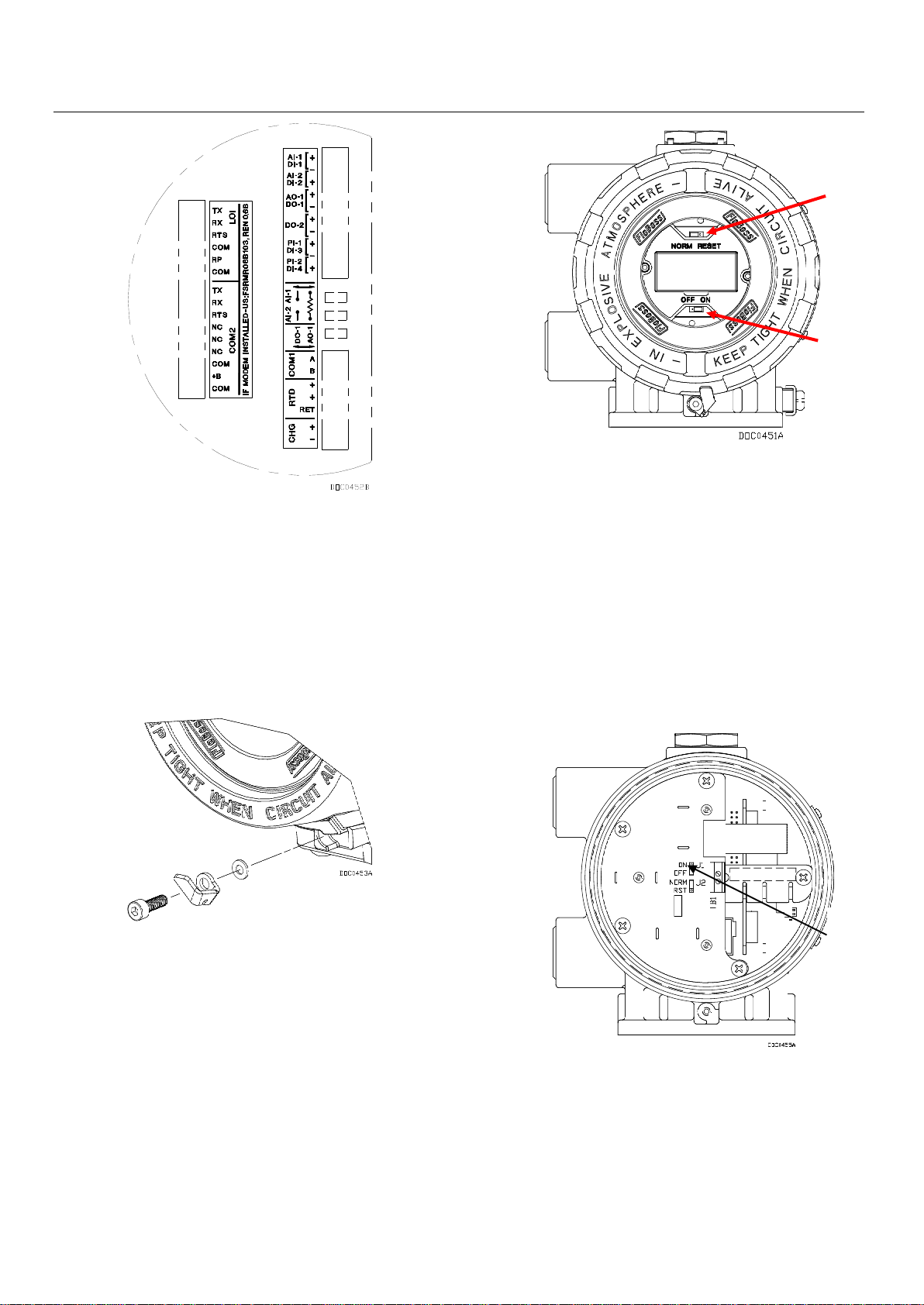
6. The FloBoss 104 ships with the NORM/RESET jumper
in the NORM position, and the ON/OFF jumper in the OFF
position.
To apply power to the FloBoss 104:
▪ Unscrew the cover clamp at the base of the front end
cap (LCD end). See Figure 4.
Figure 4. Cover Clamp Assembly
▪ Unscrew the front end cap cover.
▪ Place the power jumper (located on the LCD if
installed or located at J1 on the Battery Charger Board)
in the ON position. See Figure 5 and Figure 6.
A
NORM/RESET Jumper
B
ON/OFF Jumper
Figure 5. Front End of FloBoss 103 (with LCD)
▪ Replace the front end cap cover (LCD end) and cover
clamp.
After the FloBoss 104 completes start-up diagnostics
(RAM and other internal checks), the optional LCD displays
the date and time to indicate that the FloBoss has
completed a valid reset sequence. If the LCD does not
come on, perform trouble-shooting for possible causes
(see Step 9).
A
ON/OFF Jumper
Figure 6. Front End of FloBoss 104 (without LCD)
7. The FloBoss 104 must be configured before it is
calibrated and placed into operation. Configuration must
be performed using ROCLINK 800 software, which runs on
a PC. The PC is normally connected to the LOI port of the
flow computer to transfer configuration data into the
FloBoss 104, although much of the configuration can be
done off-line and later loaded into the FloBoss.
B
A
A
Page 7

Safe Use Instructions – Emerson FloBoss 104
Part D301733X012
February 2018
www.Emerson.com/RemoteAutomation 5
Default values for all parameters exist in the firmware of
the FloBoss. If the default is acceptable for your
application, it can be left as it is. Perform adjustments to
the FloBoss through the configuration software. Refer to
the ROCLINK 800 Configuration Software User Manual (Part
D301159X012).
8. The calibration routines support 5-point calibration,
with the three mid-points calibrated in any order. The lowend or zero reading is calibrated first, followed by the
high-end or full-scale reading. The three mid-points can
be calibrated next, if desired. The diagnostic analog
inputs—logic voltage (E1), battery voltage (E2), and
board/battery temperature (E5)—are not designed to be
calibrated.
With the optional I/O termination points installed, the
Analog Input can be calibrated using ROCLINK 800
software.
The built-in inputs that are supported with the 5-point
calibration are:
▪ Differential pressure located at AI Point A1.
▪ Static pressure located at AI Point A2.
▪ RTD temperature located at AI Point A3.
These inputs are assigned to the first three Analog Input
points. The calibration procedure for these inputs is
described in the ROCLINK 800 Configuration Software User
Manual (Part D301159X012).
9. To troubleshoot problems with the FloBoss 104,
identify whether the problem is with the configuration or
the hardware. Check the configuration in ROCLINK 800
software to identify any incorrect settings. Inspect the
hardware for damage. Inspect the termination boards for
connection location errors.
If you are experiencing problems with the FloBoss 104 that
appear to be software related, try resetting the FloBoss
with a warm start, a cold start, or a jumper reset.
If you are experiencing problems that appear to be
hardware-related, verify the wiring. If you still experience
problems, contact your local sales office for return
authorization.
During operation, the FloBoss 104 can be monitored (to
view or retrieve current and historical data) either locally
or remotely. Local monitoring is accomplished either by
viewing the LCD panel detailed in Section 2, or by using
ROCLINK 800 software on a PC connected through the LOI
port. Remote monitoring is performed through Comm 1
or Comm 2 of the FloBoss using ROCLINK 800 software, or
host system. Refer to Figure 8 for the communication
terminations.
10. To remove the FloBoss 104 from operation.
disconnect power from the unit and then remove all
external wiring connections. Remove the gas lines. Finally
remove the FloBoss housing from the pipestand or orifice
plate. The FloBoss may be placed in a box for
transportation.
DANGER
Take care when removing gas lines from the FB104.
Use one wrench to prevent the sensor connector from
moving, and use a second wrench to disconnect the
gas line. Allowing the sensor to rotate will damage the
internal wiring.
Figure 7. FB104 Pulse Interface Housing
When connecting gas pressure lines to the optional
Pulse Interface module, note the maximum working
pressure limits to the individual P1 and P2 sensors
based on the model number of the module. For
example, Figure 7 shows a model PM24 module with
its P1 (300 PSIG/2068 kPa) and P2 (1000 PSIG/6894
kPa) sensor ranges.
Page 8

Safe Use Instructions – Emerson FloBoss 104 Flow Manager
Part D301733X012
February 2018
6 www.Emerson.com/RemoteAutomation
A
FloBoss 104 nameplate
B
DVS Sensor label
Figure 8. FloBoss 104 Dimensions
A
¾ - 14 NPT Field Wiring entries
Figure 9. FloBoss 104 Mounting Styles
B
A
B
A
Page 9

Safe Use Instructions – Emerson FloBoss 104
Part D301733X012
February 2018
For customer service and technical support,
visit www.Emerson.com/SupportNet.
Global Headquarters,
North America, and Latin America:
Emerson Automation Soltuions
Remote Automation Solutions
6005 Rogerdale Road
Houston, TX 77072 U.S.A.
T +1 281 879 2699 | F +1 281 988 4445
www.Emerson.com/RemoteAutomation
© 2015-2018 Remote Automation Solutions, a business unit of Emerson Automation
Solutions. All rights reserved.
This publication is for informational purposes only. While every effort has been made to ensure
accuracy, this publication shall not be read to include any warranty or guarantee, express or
implied, including as regards the products or services described or their use or applicability.
Remote Automation Solutions (RAS) reserves the right to modify or improve the designs or
specifications of its products at any time without notice. All sales are governed by RAS terms
and conditions which are available upon request. RAS accepts no responsibility for proper
selection, use or maintenance of any product, which remains solely with the purchaser and/or
end-user.
Europe:
Emerson Automation Solutions
Remote Automation Solutions
Unit 8, Waterfront Business Park
Dudley Road, Brierley Hill
Dudley UK DY5 1LX
T +44 1384 487200 | F +44 1384 487258
Middle East/Africa:
Emerson Automation Solutions
Remote Automation Solutions
Emerson FZE
P.O. Box 17033
Jebel Ali Free Zone – South 2
Dubai U.A.E.
T +971 4 8118100 | F +971 4 8865465
Asia-Pacific:
Emerson Automation Solutions
Remote Automation Solutions
1 Pandan Crescent
Singapore 128461
T +65 6777 8211| F +65 6777 0947
Remote Automation Solutions
Page 10

Page 11

Anleitung zur sicheren Verwendung – Emerson FloBoss 104 Durchfluss-Computer
Teile-Nr. D301733X012
Februar 2018
Remote Automation Solutions
Emerson FloBoss™ 104 Durchfluss-Computer
Abbildung 1. FloBoss 104 Durchfluss-Computer – Typenschild
(Abbildung: ATEX-Version)
Verwenden Sie diese Sicherheitsvorschriften zusammen
mit der Betriebsanleitung des FloBoss 103 und FloBoss 104
Durchfluss-Computers (Teil D301153X012). Die
vollständigen Warnhinweise und Beschreibungen von
Verfahren zur Installation sowie Störungsanalyse und beseitigung finden Sie in der Betriebsanleitung.
Der FloBoss 104 Durchfluss-Computer mit ATEX- oder
IECEx-Zulassung für druckfeste Kapselung kann mit
optionaler EIA-232-Kommunikation (RS-232), analoger
Modemkommunikation oder Impulsschnittstellenmodul
(PIM) bestellt werden.
Besondere Voraussetzungen für die sichere
Verwendung des FloBoss 104
▪ Betriebstemperatur: –40 °C bis +75 °C
▪ Sicherstellen, dass das Gerät durch die
Wärmeübertragung der Flüssigkeit nicht auf eine
Temperatur erhitzt wird, die der
Selbstentzündungstemperatur des vorhandenen
Gases entspricht.
Konformitätserklärung
Remote Automation Solutions erklärt hiermit, dass das
Produkt FloBoss 104 den grundlegenden Anforderungen
und anderen relevanten Vorschriften der EU-Richtlinien
2004/108/EG (EMV), 94/9/EG (ATEX) und 97/23/EG (PED)
entspricht.
GEFAHR
Wenn Geräte in einem explosionsgefährdeten Bereich
installiert werden, so muss darauf geachtet werden, dass
alle ausgewählten Installationskomponenten für den
Einsatz in solchen Bereichen zugelassen sind. Installationsund Wartungsarbeiten dürfen nur dann ausgeführt
werden, wenn der Arbeitsbereich nicht in einer
explosionsgefährdeten Zone liegt. Installationsarbeiten in
einem explosionsgefährdeten Bereich können zu
Personen- und/oder zu Sachschäden führen.
Vor der Verkabelung des Gerätes stets die
Spannungsversorgung vom FloBoss trennen. Die
Verkabelung bei an die Spannungsversorgung
angeschlossenem Gerät kann zu Personen- und/oder
Sachschäden führen.
Um elektrische Schäden bei Arbeiten im Geräteinneren zu
vermeiden, müssen die erforderlichen
Vorsichtsmaßnahmen zur Vermeidung elektrostatischer
Entladungen eingehalten werden, zum Beispiel durch das
Tragen eines Antistatikbands.
Die auf dem Typenschild des DVS-Sensors angegebenen
Höchstwerte für Differenzdruck und statischen Druck
dürfen nicht überschritten werden.
Abdeckungen nur abnehmen, wenn der Arbeitsbereich
nicht explosionsgefährdet ist.
Wenn der FB104 mit einer HochleistungsSpannungsquelle aufgeladen und das Akkuladegerät nach
dem Laden nicht von der Spannungsversorgung getrennt
wird, kann dies zu einer Überladung und zum Ausfall des
Akkus führen. Siehe Abschnitt 3.5.1 „Überladungspotenzial“
in der Betriebsanleitung des FloBoss 103 und FloBoss 104
Durchfluss-Computers (Teil D301153X012).
Page 12

Anleitung zur sicheren Verwendung – Emerson FloBoss 104 Durchfluss-Computer
Teile-Nr. D301733X012
Februar 2018
2 www.Emerson.com/RemoteAutomation
Technische Daten
SPANNUNGSVERSORGUNG
Externer Ladestromeingang: 8–28 VDC,
Verpolungsschutz
Eingangsstrom: 10–15 mA nominal; 20 mA bei 100 %
Einschaltdauer (ohne Laden der Batterie)
GEHÄUSE
Gehäuse und Deckel: Druckguss-Aluminiumlegierung
mit Iridite-Beschichtung und Lackierung;
Edelstahlausführung (CF8M) lieferbar
UMGEBUNGSBEDINGUNGEN
Betriebstemperatur: –40 bis +75 C
Digitalanzeiger: –20 bis +75 C
Lagerungstemperatur: –50 bis +85 C
Luftfeuchtigkeit im Betrieb: 5 bis 95 %,
nichtkondensierend
GEWICHT
4,30 kg (9,5 lb) (Aluminium)
ZULASSUNGEN:
ATEX-Version (druckfeste Kapselung und Typ n)
Bewertet nach Zulassungsnormen:
(Druckfeste Kapselung) (Typ n)
EN 60079-0 (2012) EN 60079-0 (2012)
EN 60079-1 (2007) EN 60079-15 (2010)
IEC 60529 IEC 60529
LCIE-zertifiziert als Modell W40116
ATEX Cert LCIE 03ATEX6221 X/06
ATEX Cert LCIE 13ATEX1033 X/01
Produktkennzeichnungen für explosionsgefährdete
Bereiche:
Ex d IIB T5 Gb (-40°C ≤ T
amb
≤ +75°C), IP66
Ex nA IIB T3 Gc (-40°C ≤ T
amb
≤ +75°C), IP66
II 2/3 G. 0081
Technische Daten
IECEx-Version (druckfeste Kapselung und Typ n)
Bewertet nach Zulassungsnormen:
IEC 60079-0 (2011)
IEC 60079-1 (2007)
IEC 60079-15 (2010)
IEC 60529
CSA-zertifiziert als Modell W40149
IEC Cert IECEx LCI 08.0039 (druckfeste Kapselung)
IEC Cert IECEx LCI 08.0015 (Typ n)
Produktkennzeichnungen für explosionsgefährdete
Bereiche:
Ex d IIB T5 Gb (-40°C ≤ T
amb
≤ +75°C), IP66
Ex nA IIC T3 Gc (-40°C ≤ T
amb
≤ +75°C), IP66
IECEx-Version (nur Typ n)
Bewertet nach Zulassungsnormen:
IEC 60079-0 (2011)
IEC 60079-15 (2010)
IEC 60529
CSA-zertifiziert als Modell W40150
IEC Cert IECEx LCI 08.0015 (Typ n)
Produktkennzeichnungen für explosionsgefährdete
Bereiche:
Ex nA IIC T3 Gc (-40°C ≤ T
amb
≤ +75°C), IP66
Für Installation, Wartung sowie Störungsanalyse
und -beseitigung sind die folgenden Hilfsmittel bzw.
Werkzeuge erforderlich:
▪ PC mit Microsoft
®
Windows® 7, Windows 8.1 oder
Windows 10 und der Emerson Field Tools
Konfigurationssoftware (mit der ROCLINK™ 800
Konfigurationssoftware).
▪ Kreuzschlitzschraubendreher
▪ Schlitzschraubendreher
▪ Sechskantschlüssel (M4)
1. Der FloBoss 104 wird in einem Karton geliefert. Das
Gerät aus dem Karton herausnehmen.
2. Einen geeigneten Standort für den FloBoss
103 wählen. Bei der Auswahl eines Einbauortes alle
Abstände prüfen. Ausreichend Raum für die Kabel und für
Wartungstätigkeiten freilassen. Der optionale
Digitalanzeiger sollte für den Bediener vor Ort sichtbar
und zugänglich sein. Siehe Abbildung 8.
3. Der FloBoss 104 kann mit einer der folgenden
Methoden montiert werden:
▪ Montage an einem 50 mm-Standrohr (2 in.). Das
Standard Rosemount 50 mm (2 in.)-StandrohrMontagekit verwenden (wobei die Impulsleitung den
FloBoss103 mit der Messleitung verbindet).
Page 13

Anleitung zur sicheren Verwendung – Emerson FloBoss 104 Durchfluss-Computer
Teile-Nr. D301733X012
Februar 2018
www.Emerson.com/RemoteAutomation 3
Sicherstellen, dass das Standrohr alle
Gewichtsanforderungen erfüllt und die Installation den
örtlichen Bauvorschriften entspricht. Siehe Abbildung 9.
Hinweis: Das Rosemount Standrohr-Montagekit ist
nicht für das Edelstahlgehäuse geeignet. Eine
geeignete Montagevorrichtung muss vom Kunden
bereitgestellt werden.
▪ Direktmontage an einem Messgerätegehäuse.
4. Der FloBoss muss ordnungsgemäß geerdet werden.
Der FloBoss 104 verfügt über eine Erdungsschraube außen
am Gehäuse und zwei Erdungsschrauben innen im
Gehäuse. Siehe Abbildung 2.
A
Innenliegende Erdungsschrauben
B
Außenliegende Erdungsschraube
Abbildung 2. Rückseite des FloBoss 104 (mit Anschlussplatine)
Eine gute Erdung des FloBoss 104 kann Einflüsse durch
elektrisches Rauschen auf den Gerätebetrieb minimieren
und schützt vor Überspannungen. Der FloBoss bietet
Überspannungsschutz für eingebaute
Feldverkabelungseingänge und -ausgänge. Bei Systemen
mit Gleichspannungsversorgung sollte zum Schutz der
installierten Geräte vor Blitzeinschlag und Überspannungen
ein Überspannungsschutzgerät an der
Spannungseinspeisung installiert werden. Außerdem kann
für die optionale Analogmodem-Kommunikationskarte ein
Überspannungsschutz vorgesehen werden.
Bei allen Erdungen darf die mit einem Erdungsprüfgerät
gemessene Impedanz des Erdungsstabs oder -netzes
maximal 25 Ohm betragen. Der Widerstand des Erdleiters
darf zwischen der Gehäusemasse des FloBoss und dem
Erdungsstab oder
-netz maximal 1,0 Ohm betragen.
Wenn die Impedanz zwischen Rohrleitung und Erdung
über 2 Ohm liegt, muss die FloBoss-Installation elektrisch
isoliert und ein Erdungssystem mit Erdungsstab oder -netz
installiert werden.
Für die E/A-Signale wird ein isoliertes, abgeschirmtes,
verdrilltes Doppelkabel empfohlen. Durch die Verdrillung
und die Abschirmung werden Signalfehler durch EMS
(elektromagnetische Störung), RFI (Funkstörung) und
Transienten minimiert.
5. Der FloBoss muss mit einer Spannungsversorgung,
E/A-Geräten und Kommunikationsgeräten verbunden
werden. Die externen Anschlüsse (oder Feldanschlüsse)
befinden sich alle auf der Anschlussplatine. Die
Klemmleiste ist für Adern mit einen Durchmesser bis zu
1,29 mm (AWG 16) geeignet.
Die Anschlüsse auf der FloBoss-Anschlussplatine sind
Schraubklemmen. Für den Anschluss der Spannungsversorgung
(CHG+/CHG–) wird ein beweglicher Stecker verwendet, der für
Adern mit einem Durchmesser bis zu 1,29 mm (AWG 16)
geeignet ist. Für den Anschluss immer das Kabelende abisolieren
(maximal 6 mm), in die Klemme unter die Klemmschraube
einführen und die Schraube dann mit einem Drehmoment von
0,25 Nm festziehen.
Die Feldverkabelung wird über Kabeleinführungen zu den
Anschlussklemmen geführt. Um die druckfeste Kapselung
des Gehäuses zu erhalten, dürfen die Metallblindstopfen
an den unbenutzten Einführungen nicht entfernt werden.
Werden diese Stopfen aus irgendeinem Grund entfernt,
dürfen sie nur durch zugelassene Kabelverschraubungen
oder Gewindeadapter ersetzt werden, die dem
Gerätestandard entsprechen oder diesen übertreffen.
GEFAHR
Die Klemmenschrauben nicht zu fest anziehen.
HINWEISE: Vor dem Einschalten der
Spannungsversorgung die Polarität des
Eingangsstroms prüfen.
Um Kurzschlüsse zu vermeiden, sollten die Adern der
eingeführten Kabel so kurz wie möglich abisoliert sein. Bei
der Herstellung von Verbindungen auf Zugentlastung
achten.
Der FloBoss 103 akzeptiert Eingangsspannungen von 8,0
bis 28 Volt an den Ladeklemmen (CHG+/CHG–) ohne
externe Strombegrenzung (die interne Strombegrenzung
beträgt 200 mA).
Die Anschlussklemmen sind auf einem Aufkleber auf der
Anschlussplatine mit CHG+ für den Plusanschluss und mit
CHG– für den Minusanschluss der Spannungsversorgung
gekennzeichnet. Siehe Abbildung 3.
A
B
Page 14
Anleitung zur sicheren Verwendung – Emerson FloBoss 104 Durchfluss-Computer
Teile-Nr. D301733X012
Februar 2018
4 www.Emerson.com/RemoteAutomation
Abbildung 3. Anschlussplatine
6. Die Steckbrücke NORM/RESET des FloBoss 103 ist bei
Auslieferung in der Position NORM und die Steckbrücke
ON/OFF in der Position OFF.
Aktivieren der Spannungsversorgung des FloBoss 104:
▪ Die Deckelklemme unten am vorderen
Gehäusedeckel (auf der Seite des Digitalanzeigers)
lösen. Siehe Abbildung 4.
Abbildung 4. Deckelklemme
▪ Den vorderen Gehäusedeckel abschrauben.
▪ Die Steckbrücke für die Spannungsversorgung (auf dem
Digitalanzeiger oder J1 auf der Batterieladeplatine) in die
Position ON setzen. Siehe Abbildung 5 und Abbildung 6.
A
Steckbrücke NORM/RESET
B
Steckbrücke ON/OFF
Abbildung 5. Vorderseite des FloBoss 104 (mit
Digitalanzeiger)
▪ Den vorderen Gehäusedeckel (auf der Seite des
Digitalanzeigers) wieder einsetzen.
Nach Abschluss der Einschaltdiagnose des FloBoss 103
(RAM und andere interne Prüfungen) erscheinen Datum
und Uhrzeit auf dem optionalen Digitalanzeiger, um die
erfolgreiche Initialisierung anzuzeigen. Wenn der
Digitalanzeiger nichts anzeigt, für mögliche Ursachen die
Störungsanalyse und -beseitigung (siehe Schritt 9)
durchführen.
A
Steckbrücke ON/OFF
Abbildung 6. Vorderseite des FloBoss 103
(ohne Digitalanzeiger)
7. Der FloBoss 104 muss vor der Kalibrierung und
Inbetriebnahme konfiguriert werden. Die Konfiguration
muss mit dem Programm ROCLINK 800 auf einem PC
ausgeführt werden. Der PC wird zur Übertragung der
B
A
A
Page 15

Anleitung zur sicheren Verwendung – Emerson FloBoss 104 Durchfluss-Computer
Teile-Nr. D301733X012
Februar 2018
www.Emerson.com/RemoteAutomation 5
Konfigurationsdaten zum FloBoss 104 in der Regel mit
dem Anschluss am Bedieninterface des DurchflussComputers verbunden. Ein Großteil der Konfiguration
kann jedoch auch offline durchgeführt und zu einem
späteren Zeitpunkt in den FloBoss geladen werden.
Die Standardwerte für alle Parameter sind in der Firmware
des FloBoss definiert. Wenn die Vorgaben für die jeweilige
Anwendung akzeptabel sind, können sie unverändert
übernommen werden. Änderungen an den FloBossEinstellungen werden mit dem Konfigurationsprogramm
vorgenommen. Siehe Betriebsanleitung des ROCLINK 800
Konfigurationsprogramms (Teil D301159X012).
8. Die Kalibrierungsroutinen unterstützen 5-Punkt-
Kalibrierung, wobei die drei mittleren Punkte in beliebiger
Reihenfolge kalibriert werden können. Zuerst wird der
Messanfang bzw. der Nullpunkt und danach das Messende
bzw. der Messbereichsendwert kalibriert. Die drei mittleren
Punkte können, falls erforderlich, als Nächstes kalibriert
werden. Die für Diagnosezwecke vorgesehenen
Analogeingänge – logische Spannung (E1),
Batteriespannung (E2) und Platinen-/
Batterietemperatur (E5) – müssen nicht kalibriert werden.
Wenn die optionalen E/A-Anschlusspunkte installiert sind,
kann der Analogeingang mit dem Programm ROCLINK
800 kalibriert werden.
Die folgenden eingebauten Eingänge unterstützen die 5Punkt-Kalibrierung:
▪ Differenzdruck an AI Punkt A1
▪ Statischer Druck an AI Punkt A2
▪ Widerstandsthermometer an AI Punkt A3
Diese Eingänge sind den ersten drei Analogeingängen
zugeordnet. Eine Beschreibung der Kalibrierung für diese
Eingänge finden Sie in der Betriebsanleitung des ROCLINK
800 Konfigurationsprogramms (Teil D301159X012).
9. Zur Analyse und Beseitigung von Problemen mit dem
FloBoss 104 zunächst bestimmen, ob das Problem an der
Konfiguration oder an der Hardware liegt. Die
Konfiguration im Programm ROCLINK 800 auf falsche
Einstellungen prüfen. Die Hardware auf Beschädigungen
untersuchen. Die Anschlussplatinen auf Anschlussfehler
überprüfen.
Wenn Probleme mit dem FloBoss 104 auftreten, die
möglicherweise auf die Software zurückzuführen sind, den
FloBoss mit einem Warmstart, einem Kaltstart oder einer
Initialisierung mit der Steckbrücke zurücksetzen.
Falls Probleme auftreten, deren Ursache in der Hardware
vermutet wird, die Verkabelung prüfen. Falls die Probleme
weiterhin bestehen, wenden Sie sich an Ihr lokales
Vertriebsbüro, um eine Rückgabegenehmigung zu
erhalten.
Der FloBoss 104 kann während des Betriebs lokal oder
extern überwacht werden (zum Anzeigen oder Abrufen
von aktuellen oder historischen Daten). Lokale
Überwachung ist entweder durch Ablesen des in Abschnitt
2 beschriebenen Digitalanzeigers oder mit dem
Programm ROCLINK 800 auf einem über den Anschluss
am Bedieninterface verbundenen PC möglich. Externe
Überwachung kann über Comm 1 oder Comm 2 des
FloBoss mit dem Programm ROCLINK 800 oder einem
Hostsystem durchgeführt werden.
Kommunikationsanschlüsse siehe Abbildung 8.
10. Um den FloBoss 104 außer Betrieb zu setzen, die
Spannungsversorgung vom Gerät trennen und dann alle
externen Kabelverbindungen entfernen. Die Gasleitungen
entfernen. Zum Schluss das FloBoss-Gehäuse vom
Standrohr oder der Messblende abnehmen. Der FloBoss
kann für den Transport in einen Karton gelegt werden.
GEFAHR
Gasleitungen mit Vorsicht vom FB104 trennen. Die
Position des Sensoranschlusses mit einem
Schraubenschlüssel fixieren und die Gasleitung dann mit
einem zweiten Schraubenschlüssel trennen. Wenn sich
der Sensor dreht, wird die interne Verdrahtung
beschädigt.
Abbildung 7. FB104-Impulsschnittstellengehäuse
Beim Anschließen von Gasdruckleitungen an das optionale
Impulsschnittstellenmodul die maximalen
Arbeitsdruckwerte der einzelnen P1- und P2-Sensoren
entsprechend der Modellnummer des Moduls beachten.
Zum Beispiel zeigt Abbildung 7 ein Modulmodell PM24 mit
P1 SENSORMARKIERUNG
P2 SENSORMARKIERUNG
OPTIONALES MESSSYSTEM-
GEHÄUSE
MODULMODELLNUMMER
(BEISPIEL)
IMPULSSCHNITTSTELLE
MODULSERIE
P2 SENSOR-BEREICHSCODE
P1 SENSOR-BEREICHSCODE
BEREICHSCODE
MAX.
BETRIEBSDRUCK
SENSORMARKIERUNG
0
STOPFEN
–
1
100 psig
689 kPa
XXXXXX – 100
2
300 psig
2068 kPa
XXXXXX – 300
4
1000 psig
6094 kPa
XXXXXX – K1
Page 16

Anleitung zur sicheren Verwendung – Emerson FloBoss 104 Durchfluss-Computer
Teile-Nr. D301733X012
Februar 2018
6 www.Emerson.com/RemoteAutomation
den Sensorbereichen P1 (2068 kPa/300 psig) und P2
(6894 kPa/1000 psig).
A
FloBoss 104 – Typenschild
B
DVS Sensor – Typenschild
Abbildung 8. FloBoss 104 – Abmessungen
A
¾ - 14 NPT-Eingänge für Feldverkabelung
Abbildung 9. FloBoss 104 - Montagearten
A
Page 17

Anleitung zur sicheren Verwendung – Emerson FloBoss 104 Durchfluss-Computer
Teile-Nr. D301733X012
Februar 2018
Kundendienst und technische Unterstützung
finden Sie unter
www.Emerson.com/SupportNet.
Weltweite Firmenzentrale
Nordamerika/Lateinamerika:
Emerson Automation Solutions
Remote Automation Solutions
6005 Rogerdale Road
Houston, TX 77072, USA
Tel.: +1 281 879 2699 | Fax: +1 281 988 4445
www.Emerson.com/RemoteAutomation
Europa:
Emerson Automation Solutions
Remote Automation Solutions
Unit 8, Waterfront Business Park
Dudley Road, Brierley Hill
Dudley UK DY5 1LX
Tel.: +44 1384 487200 | Fax: +44 1384 487258
Naher Osten/Afrika:
Emerson Automation Solutions
Remote Automation Solutions
Emerson FZE
P.O. Box 17033
Jebel Ali Free Zone – South 2
Dubai, Vereinigte Arabische Emirate
Tel.: +971 4 8118100 | Fax: +971 4 8865465
Asien/Pazifik:
Emerson Automation Solutions
Remote Automation Solutions
1 Pandan Crescent
Singapur 128461
Tel.: +65 6777 8211| Fax: +65 6777 0947
Remote Automation Solutions
Page 18

Page 19

Consignes de sécurité – Calculateur de débit Emerson FloBoss 104
réf. D301733X012
Février 2018
Remote Automation Solutions
Calculateur de débit Emerson FloBossTM 104
Figure 1. Plaque signalétique du calculateur de débit
FloBoss 104 (version ATEX illustrée)
Utilisez ces consignes avec le Manuel d’instructions du
calculateur de débit FloBoss 103 et FloBoss 104 (réf.
D301153X012). Consultez ce manuel pour obtenir toutes
les mesures de précaution, descriptions d’installation et
procédures de dépannage.
Le calculateur de débit FloBoss 104 avec homologation de
résistance au feu ATEX ou IECEx est disponible avec les
options de communication EIA-232 (RS-232), modem
commuté ou modèle d'interface à impulsions (PIM).
Conditions spéciales pour une utilisation en
toute sécurité du FloBoss 104
▪ Température ambiante de fonctionnement : -40 °C à
+75 °C.
▪ Assurez-vous que le transfert de fluide thermique ne
surchauffe pas l’équipement à une température
correspondant à la température de combustion
spontanée du gaz environnant.
Déclaration de conformité
Remote Automation Solutions déclare par la présente que
le produit FloBoss 104 est conforme aux exigences
essentielles et aux autres dispositions applicables des
Directives européennes 2004/108/EC (EMC), 94/9/EC
(ATEX) et 97/23/EC (PED), le cas échéant.
DANGER
Si les unités sont installées dans une zone dangereuse,
assurez-vous que les étiquettes des composants
sélectionnés autorisent leur usage dans une telle zone.
L’installation et la maintenance ne doivent être effectuées
que lorsque la zone ne présente aucun risque.
L’installation dans une zone dangereuse peut entraîner
des blessures ou des dégâts matériels.
Éteignez toujours le FloBoss avant toute intervention sur le
câblage. Toute intervention sur un équipement sous
tension pourrait entraîner des blessures ou des dégâts
matériels.
Pour éviter d’endommager les circuits lors d’une
intervention à l’intérieur de l’unité, appliquez les
précautions pertinentes concernant les décharges
électrostatiques, notamment le port d’un bracelet
antistatique.
N’ouvrez pas les couvercles à moins d’être sûr que la zone
ne présente aucun risque.
Le raccordement du FB104 à une source d’alimentation
continue à forte puissance sans avoir déposé au préalable
le module du chargeur de batterie pourrait provoquer une
surcharge et une défaillance de la batterie. Reportez-vous
à la Section 3.5.1 Potentiel de surcharge dans le Manuel
d’instructions du calculateur de débit FloBoss 103 et 104 (réf.
D301153X012).
Page 20

Consignes de sécurité – Calculateur de débit Emerson FloBoss 104
réf. D301733X012
Février 2018
2 www.Emerson.com/RemoteAutomation
Spécifications
ALIMENTATION
Prise de recharge externe : 8 à 28 Vcc, protection
contre l'inversement de polarité
Courant d'entrée : 10-15 mA nominal. 20 mA à 100 %
du cycle de service (charge de la batterie non
comprise)
COFFRET
Boîtier et capuchon : Alliage d'aluminium moulé sous
pression avec plaquage et peinture iridiés. Version en
acier inoxydable (CF8M) disponible
CONDITIONS AMBIANTES
Température ambiante de fonctionnement : -40 à
+75 C
Indicateur LCD : -20 à +75 C
Température de stockage : -50 à +85 C
Humidité relative de fonctionnement : 5 à 95 %, sans
condensation
POIDS
4,30 kg (9,5 lb) (aluminium)
CERTIFICATIONS:
Version ATEX (antidéflagrance et Type « n »)
Évalué selon les normes de certification :
(Antidéflagrance) (Type « n »)
EN 60079-0 (2012) EN 60079-0 (2012)
EN 60079-1 (2007) EN 60079-15 (2010)
CEI 60529 CEI 60529
Certifié par LCIE en tant que modèle W40116.
Homologation ATEX LCIE 03ATEX6221 X/06
Homologation ATEX LCIE 13ATEX1033 X/01
Marquages du produit pour les zones dangereuses :
Ex d IIB T5 Gb (-40°C ≤ T
amb
≤ +75°C), IP66
Ex nA IIB T3 Gc (-40°C ≤ T
amb
≤ +75°C), IP66
II 2/3 G. 0081
Spécifications
Version IECEx (antidéflagrance et Type « n »)
Évalué selon les normes d'agrément :
CEI 60079-0 (2011)
CEI 60079-1 (2007)
CEI 60079-15 (2010)
CEI 60529
Certifié par CSA comme modèle W40149.
Homologation CEI IECEx LCI 08.0039 (Antidéflagrance)
Certification CEI IECEx LCI 08.0015 (Type « n »)
Marquages du produit pour les zones dangereuses :
Ex d IIB T5 Gb (-40°C ≤ T
amb
≤ +75°C), IP66
Ex nA IIC T3 Gc (-40°C ≤ T
amb
≤ +75°C), IP66
Version IECEx (Type « n » seulement)
Évalué selon les normes d'agrément :
CEI 60079-0 (2011)
CEI 60079-15 (2010)
CEI 60529
Certifié par CSA comme modèle W40150
Homologation CEI IECEx LCI 08.0015 (Type « n »)
Marquages du produit pour les zones dangereuses :
Ex nA IIC T3 Gc (-40°C ≤ T
amb
≤ +75°C), IP66
Les outils suivants sont nécessaires pour l’installation, la
maintenance et le dépannage :
▪ Ordinateur PC exécutant Microsoft® Windows® 7,
Windows 8.1 ou Windows 10 et le logiciel de
configuration Emerson Field Tools (avec logiciel de
configuration ROCLINK™ 800).
▪ Tournevis Phillips (cruciforme)
▪ Tournevis à tête plate
▪ Clé à cliquet hexagonale (M4)
1. Vous recevrez le FloBoss 104 dans un emballage.
Retirez-le de l'emballage.
2. Trouvez un emplacement convenable pour le FloBoss
104. Lors du choix d’un emplacement, assurez-vous de
bien vérifier tous les dégagements. Veillez à laisser un
espace suffisant pour le câblage et l’entretien. L’écran LCD
en option doit être visible et accessible pour l’opérateur
sur place. Reportez-vous à la Figure 8.
3. Le montage du FloBoss 104 peut être effectué à l’aide
de l’une des méthodes suivantes:
▪ Tube support monté sur un tube support de 2 pouces.
Utilisez le kit de montage de tube Rosemount de
50 mm (2 pouces) (avec les lignes d’impulsion qui
connectent le FloBoss 104 au compteur). Veillez à ce
que le tube support soit conforme à toutes les
exigences de poids et que l’installation soit conforme
aux codes de bâtiment locaux. Voir la Figure 9.
Page 21

Consignes de sécurité – Calculateur de débit Emerson FloBoss 104
réf. D301733X012
Février 2018
www.Emerson.com/RemoteAutomation 3
Remarque : Le kit de montage de tube Rosemount
n’est pas adapté au boîtier en acier inoxydable. Les
clients doivent effectuer un montage approprié.
▪ Montage direct sur un boîtier d'indicateur.
4. Le FloBoss doit être correctement mis à la terre. Le
FloBoss 104 a une vis de masse à l’extérieur du boîtier et
deux vis de masse à l’intérieur du boîtier. Voir la Figure 2.
A
Vis de masse internes
B
Vis de masse externe
Figure 2. Extrémité arrière du FloBoss 104
(avec carte de raccordement)
La mise à la terre appropriée du FloBoss 104 aide à réduire les
effets du bruit électrique lors du fonctionnement de l’unité et
offre une protection contre la foudre. Le FloBoss offre la
protection contre la foudre pour les entrées et les sorties
intégrées du câblage sur site. Installez un dispositif de
protection contre les surtensions au niveau du sectionneur
d’entretien sur les systèmes de source de tension CC pour
offrir la protection contre la foudre et les surtensions sur les
équipements installés. Vous pouvez également envisager
d’acquérir un dispositif de protection contre les surtensions
du téléphone pour la carte de communications par modem
commuté en option.
Toutes les prises de terre doivent avoir une impédance de
tige ou de grille de mise à la terre égale ou inférieure à
25 ohms, conformément aux mesures effectuées à l’aide
d’un dispositif d’essai de la mise à la terre. Le conducteur de
terre doit avoir une résistance égale ou inférieure à 1 ohm
entre le boîtier du FloBoss et la tige ou la grille de mise à la
terre.
Si l’impédance de la conduite à la terre est supérieure à
2 ohms, l’installation du FloBoss doit être électriquement
isolée et un système de tige ou de grille de mise à la terre
doit être installé.
Il est recommandé que le câble des signaux d’entrée et de
sortie soit isolé, blindé et à paire torsadée. La paire
torsadée et le blindage minimisent les erreurs de signal
causées par l’interférence électromagnétique, les
perturbations radioélectriques et les transitoires.
5. Le FloBoss doit être branché à l’alimentation, aux
dispositifs d’entrée et de sortie et aux périphériques de
communication. Les connexions externes, ou bornes
inductrices, sont toutes situées sur la carte de
raccordement. Le bloc de jonction accepte les fils d’une
taille maximale de 1,29 mm.
Les connecteurs de la carte de raccordement du FloBoss
utilisent des bornes de compression. Le raccord de
terminaison électrique d’entrée (CHG+ / CHG-) utilise un
connecteur amovible et accepte les câbles d’une taille
maximale de 1,29 mm. Dans tous les cas, effectuez les
connexions en dénudant l’extrémité (6 mm maximum) du
fil, en insérant l’extrémité dénudée dans le collier près de
la vis de raccordement, puis en serrant la vis à 0,25 N.m.
L’accès aux connexions de câble se fait par les entrées de
câble. Les bouchons de tuyauterie métalliques fournis
doivent rester en place sur les entrées non utilisées pour
conserver la résistance au feu du boîtier. Si ces bouchons
sont remplacés pour une quelconque raison, installez
uniquement des bouchons ou des adaptateurs à filetage
qui répondent aux classifications du produit ou à des
classifications supérieures.
DANGER
Ne serrez pas trop les vis du connecteur.
REMARQUE: Vérifiez la polarité de puissance d’entrée
avant de mettre le produit sous tension.
Les fils insérés doivent avoir une partie minimale exposée
de fil dénudé pour éviter les courts-circuits. Lorsque vous
effectuez les branchements, laissez un peu de jeu afin
d’éviter toute surtension.
Le FloBoss 104 accepte les tensions d’entrée de 8 volts à
28 volts sur les bornes de charge (CHG+ / CHG-), sans
limitation de courant externe (la limite de courant interne
est de 200 mA).
Les borniers sont repérés CHG+ pour le positif et CHGpour le négatif sur une étiquette apposée sur la carte de
raccordement. Voir la Figure 3.
A
B
Page 22

Consignes de sécurité – Calculateur de débit Emerson FloBoss 104
réf. D301733X012
Février 2018
4 www.Emerson.com/RemoteAutomation
Figure 3. Carte de raccordement
6. Le FloBoss 104 est livré avec le cavalier NORM/RESET
(Normal/Réinitialiser) en position NORM et avec le cavalier
ON/OFF (Marche/Arrêt) en position OFF.
Pour mettre le FloBoss 104 sous tension :
▪ Dévissez le collier du couvercle à l’avant du capuchon
(extrémité LCD). Voir la Figure 4.
Figure 4. Collier du couvercle
▪ Dévissez le couvercle du capuchon avant (extrémité
LCD).
▪ Placez le cavalier d’alimentation (situé sur le LCD s’il
est installé ou situé au niveau de J1 sur la carte de
charge de la batterie) en position ON (Marche).
Consultez Figure 5 et Figure 6.
A
Cavalier NORM/RESET (Normal/Réinitialiser)
B
Cavalier ON/OFF (Marche/Arrêt)
Figure 5. Extrémité avant du FloBoss 104 (avec LCD)
▪ Remplacez le couvercle du capuchon avant (extrémité
LCD) et le collier du couvercle.
Une fois que le FloBoss 104 a terminé les diagnostics de
démarrage (RAM et autres vérifications internes), le LCD
en option affiche la date et l’heure pour indiquer que le
FloBoss a terminé une séquence de réinitialisation valide.
Si le LCD ne s’allume pas, effectuez la procédure de
dépannage pour en connaître les causes possibles (voir
l’Étape 9).
A
Cavalier ON/OFF (Marche/Arrêt)
Figure 6. Extrémité avant du FloBoss 104 (sans LCD)
7. Le FloBoss 104 doit être configuré avant d’être
étalonné et mis en fonctionnement. La configuration doit
être effectuée à l’aide du logiciel ROCLINK 800, exécuté
sur un PC. Le PC est normalement connecté au port LOI du
calculateur de débit pour transférer les données de
configuration au FloBoss 104, même si une grande partie
B
A
A
Page 23

Consignes de sécurité – Calculateur de débit Emerson FloBoss 104
réf. D301733X012
Février 2018
www.Emerson.com/RemoteAutomation 5
de la configuration peut être effectuée hors ligne, puis
chargée ultérieurement dans le FloBoss.
Les valeurs par défaut pour tous les paramètres sont
disponibles dans le micrologiciel du FloBoss. Si la valeur
par défaut est acceptée pour votre application, elle peut
être laissée telle quelle. Effectuez les ajustements sur le
FloBoss en utilisant le logiciel de configuration. Reportezvous au Manuel d’utilisation du logiciel de configuration
ROCLINK™ 800 (réf. D301159X012).
8. Les routines d’étalonnage prennent en charge
l’étalonnage en 5 points, l’ordre d’étalonnage des trois
points intermédiaires étant indifférent. La valeur inférieure
ou zéro est étalonnée en premier, suivie par la valeur
supérieure ou l’étendue de l’échelle. Les trois points
intermédiaires peuvent être étalonnés ultérieurement, au
besoin. Les entrées analogiques du diagnostic — tension
logique (E1), tension de batterie (E2) et température de la
carte/batterie (E5) — ne sont pas conçues pour être
étalonnées.
Avec les points de raccordement d’entrée et de sortie
installés, l’entrée analogique peut être étalonnée à l’aide
du logiciel ROCLINK 800.
Les entrées intégrées qui sont prises en charge avec
l’étalonnage à 5 points sont :
▪ Pression différentielle située à AI point A1.
▪ Pression statique située à AI point A2.
▪ Température RTD située à AI point A3.
Ces entrées sont assignées aux premiers trois points
d’entrée analogique. La procédure d’étalonnage de ces
entrées est décrite dans le Manuel d’utilisation du logiciel de
configuration ROCLINK 800 (Réf. D301159X012).
9. Pour résoudre les problèmes relatifs au FloBoss 104,
déterminez si le problème concerne la configuration ou le
matériel. Vérifiez la configuration du logiciel ROCLINK 800
pour identifier les paramètres incorrects éventuels.
Inspectez le matériel pour voir s’il est endommagé.
Inspectez les cartes de raccordement pour voir s’il y a des
erreurs dans l’emplacement des connexions.
Si vous rencontrez des problèmes avec le FloBoss 104 qui
semblent liés au logiciel, essayez de redémarrer le FloBoss
à chaud, à froid ou en le réinitialisant avec un cavalier.
Si vous rencontrez des problèmes qui semblent liés au
matériel, vérifiez le câblage. Si les problèmes persistent,
contactez votre bureau de vente local pour l'autorisation
de retour.
Pendant le fonctionnement, le FloBoss 104 peut être
contrôlé (pour afficher ou récupérer les données actuelles
et anciennes) localement ou à distance. Le contrôle local
est effectué soit en regardant l’afficheur LCD décrit à la
Section 2 ou en utilisant le logiciel ROCLINK 800 sur un
ordinateur connecté via le port LOI. Le contrôle à distance
est effectué via Comm 1 ou Comm 2 du FloBoss, à l’aide
du logiciel ROCLINK 800 ou d’un système hôte. Reportezvous à Figure 8 pour les bornes de communication.
10. Pour retirer le FloBoss 104 du service, débranchez
l’alimentation de l’unité, puis retirez toutes les connexions
câblées externes. Retirez les conduites de gaz. En fin,
retirez le boîtier du FloBoss du tube support ou de la
plaque à orifice. Le FloBoss peut être placé dans une boîte
pour le transport.
DANGER
Prenez des précautions lors du retrait des conduits de gaz
du FB104. Utilisez une clé pour empêcher le connecteur
du capteur de bouger et utilisez une deuxième clé pour
débrancher la conduite de gaz. Toute rotation du capteur
endommagera le câblage interne.
Figure 7. Boîtier de l'interface à impulsions du FB104
Lors de la connexion des conduites de la pression du gaz
au module d'interface à impulsions en option, notez les
limites maximales de pression de fonctionnement sur les
capteurs individuels P1 et P2 en fonction du numéro de
modèle du module. Par exemple, la Figure 7 illustre le
module de modèle PM24 avec les gammes de ses capteurs
P1 (300 PSIG/2 068 kPa) et P2 (1 000 PSIG/6 894 kPa).
MARQUAGE DE
CAPTEUR P1
MARQUAGE DE
CAPTEUR P2
BOÎTIER D'INDICATEUR EN OPTION
N° DE MODÈLE DE
MODULE
(EXEMPLE ILLUSTRÉ)
INTERFACE D'IMPULSION
N° DE SÉRIE DE MODULE
CODE DE GAMME DE CAPTEURS P2
CODE DE GAMME DE CAPTEURS P1
CODE DE
GAMME
PRESSION DE
SERVICE
MAXIMALE
MARQUAGE DE
CAPTEUR
0
BOUCHON
S.O.
1
100 PSIG
689 kPo
XXXXXX – 100
2
300 PSIG
2 068 kPo
XXXXXX – 300
4
1 000 PSIG
6 894 kPo
XXXXXX – K1
Page 24

Consignes de sécurité – Calculateur de débit Emerson FloBoss 104
réf. D301733X012
Février 2018
6 www.Emerson.com/RemoteAutomation
A
Plaque signalétique du FloBoss 104
B
Étiquette du capteur DVS
Figure 8. Dimensions du FloBoss 104
A
Entrées de câblage sur site ¾" - 14 NPT
Figure 9. Styles de montage du FloBoss 104
A
B
A
Page 25

Consignes de sécurité – Calculateur de débit Emerson FloBoss 104
réf. D301733X012
Février 2018
Pour joindre le service clientèle et bénéficier
d’une assistance technique,
consultez la page www.Emerson.com/SupportNet
Siège social international
Amérique du Nord et Amérique latine :
Emerson Automation Solutions
Remote Automation Solutions
6005 Rogerdale Road
Houston, TX 77072 États-Unis.
T +1 281 879 2699 | F +1 281 988 4445
www.Emerson.com/RemoteAutomation
© 2015-2018 Remote Automation Solutions, une division commerciale d'Emerson
Automation Solutions. Tous droits réservés.
Cette publication est à titre informatif uniquement. Bien que tous les efforts aient été faits pour
vérifier l'exactitude des informations présentées dans ce document, ce dernier ne saurait être
considéré comme une garantie tacite ou explicite des produits ou services décrits quant à leur
utilisation ou leur applicabilité. Remote Automation Solutions (RAS) se réserve le droit de
modifier ou d'améliorer les conceptions ou les spécifications de ses produits à tout moment et
sans préavis. Toutes les ventes sont régies par les conditions générales de RAS, lesquelles sont
disponibles sur demande. RAS n'accepte aucune responsabilité quant au choix, à l'utilisation ou
à l'entretien d'un produit, laquelle incombe uniquement à l'acquéreur et/ou à l'utilisateur final.
Europe :
Emerson Automation Solutions
Remote Automation Solutions
Unit 8, Waterfront Business Park
Dudley Road, Brierley Hill
Dudley UK DY5 1LX
T +44 1384 487200 | F +44 1384 487258
Moyen-Orient/Afrique :
Emerson Automation Solutions
Remote Automation Solutions
Emerson FZE
P.O. Box 17033
Jebel Ali Free Zone – South 2
Dubai, Émirats Arabes Unis.
T +971 4 8118100 | F +971 4 8865465
Asie-Pacifique :
Emerson Automation Solutions
Remote Automation Solutions
1 Pandan Crescent
Singapour 128461
T +65 6777 8211| F +65 6777 0947
Remote Automation Solutions
Page 26

Page 27

Instruções para um uso seguro – Computador de vazão Emerson FloBoss 104
Referência D301733X012
Fevereiro de 2018
Remote Automation Solutions
Computador de vazão Emerson FloBossTM 104
Figura 1. Placa de identificação do computador de vazão
FloBoss 104 (versão ATEX mostrada)
Use esta folha de instruções com o manual de instruções
do computador de vazão FloBoss 103 e FloBoss 104
(Peça D301153X012). Para obter todos os cuidados
e descrições relacionados aos procedimentos de
instalação e solução de problemas, consulte o manual.
O computador de vazão FloBoss 104 com certificações
ATEX ou IECEx, à prova de fogo, pode ser pedido com as
portas de comunicações EIA-232 (RS-232), comunicações
de modem dial-up ou Módulo de interface de pulso (PIM)
opcionais.
Instruções para a utilização segura do FloBoss
104
▪ Temperatura ambiente operacional: -40°C a +75°C.
▪ Certifique-se de que a transferência térmica do fluido
não superaqueça o equipamento até uma
temperatura correspondente à temperatura de
combustão espontânea do gás presente.
Declaração de conformidade
Por este documento, a Remote Automation Solutions
declara que o produto FloBoss 104 está em conformidade
com os requisitos fundamentais e outras cláusulas
pertinentes das diretrizes europeias 2004/108/CE (EMC),
94/9/EC (ATEX) e 97/23/EC (PED), conforme aplicável.
PERIGO
Para instalar unidades em um local perigoso, verifique se
todos os componentes selecionados para instalação têm
etiqueta para uso nestes locais. A instalação e a
manutenção só devem ser realizadas quando se tem
conhecimento que a área não é classificada. A instalação
em um local perigoso pode causar lesão pessoal ou danos
à propriedade.
Sempre desligue a alimentação do FloBoss, antes de
manusear qualquer tipo de fiação. A fiação de um
equipamento ligado pode causar lesão pessoal ou danos à
propriedade.
Para evitar danos ao circuito ao trabalhar dentro
da unidade, tome os cuidados necessários com a descarga
eletrostática, tais como usar uma pulseira de aterramento.
Não abra as tampas, a menos que você saiba que o local
não é classificado.
A conexão do FB104 a uma fonte de alimentação de alta
voltagem, contínua, sem remover o módulo carregador
de bateria, pode resultar em sobrecarga da bateria e falha.
Consulte a Seção 3.5.1, Potencial de sobrecarga, no manual
de instruções do computador de vazão FloBloss 103 e 104
(peça D301153X012).
Page 28

Instruções para um uso seguro – Computador de vazão Emerson FloBoss 104
Referência D301733X012
Fevereiro de 2018
2 www.Emerson.com/RemoteAutomation
Especificações
ENERGIA
Entrada de alimentação externa de recarga: 8 a 28 V cc,
proteção de polaridade reversa
Corrente de entrada: 10 a 15 mA nominal. 20 mA a
100% do ciclo do serviço (recarga da bateria não
incluída)
INVÓLUCRO
Invólucro e tampa: Liga de alumínio fundido com
revestimento de iridite e tinta. Há uma versão em aço
inoxidável (CF8M) disponível
AMBIENTAIS
Temperatura ambiente operacional: -40 a +75C
Display LCD: -20 a +75C
Temperatura de armazenamento: -50 a +85C
Umidade de operação: 5 a 95% sem condensação
PESO
4,30 kg (9,5 lb) (alumínio)
CERTIFICADOS:
Versão ATEX (à prova de fogo e tipo n)
Avaliado conforme as normas de certificação:
(À prova de fogo) (Tipo n)
EN 60079-0 (2012) EN 60079-0 (2012)
EN 60079-1 (2007) EN 60079-15 (2010)
IEC 60529 IEC 60529
Certificado pela LCIE como modelo W40116
ATEX Cert LCIE 03ATEX6221 X/06
ATEX Cert LCIE 13ATEX1033 X/01
Marcação de produtos para áreas classificadas:
Ex d IIB T5 Gb (-40°C ≤ T
amb
≤ +75°C), IP66
Ex dentro da IIB T3 Gc (-40°C ≤ T
amb
≤ +75°C), IP66
II 2/3 G. 0081
Especificações
VERSÃO IECEx (à prova de fogo e tipo n)
Avaliado conforme as normas de certificação:
IEC 60079-0 (2011)
IEC 60079-1 (2007)
IEC 60079-15 (2010)
IEC 60529
Certificado pela CSA como modelo W40149
IEC Cert IECEx LCI 08.0039 (À prova de fogo)
IEC Cert IECEx LCI 08.0015 (Tipo n)
Marcação de produtos para áreas classificadas:
Ex d IIB T5 Gb (-40°C ≤ T
amb
≤ +75°C), IP66
Ex dentro da IIC T3 Gc (-40°C ≤ T
amb
≤ +75°C), IP66
VERSÃO IECEx (Somente tipo n)
Avaliado conforme as normas de certificação:
IEC 60079-0 (2011)
IEC 60079-15 (2010)
IEC 60529
Certificado pela CSA como modelo W40150
IEC Cert IECEx LCI 08.0015 (tipo n)
Marcação de produtos para áreas classificadas:
Ex dentro da IIC T3 Gc (-40°C ≤ T
amb
≤ +75°C), IP66
As ferramentas abaixo são necessárias para a instalação,
a manutenção e a solução de problemas:
▪ Computador pessoal com Microsoft® Windows® 7,
Windows 8.1, ou Windows 10 e software de
configuração para ferramentas de campo Emerson
(com software de configuração ROCLINK™ 800).
▪ Chave de fenda Phillips (cabeça cruzada).
▪ Chave de fenda simples.
▪ Chave allen sextavada (M4).
1. Você recebe o FloBoss 104 em uma caixa. Retire-o da
caixa.
2. Encontre uma localização adequada para o FloBoss
104. Ao escolher um local de instalação, verifique todos os
espaços livres. Forneça espaço livre adequado para a
fiação e para a manutenção. O LCD opcional deve ficar
visível e acessível para o operador no local. Consulte a
Figura 8.
3. A montagem do FloBoss 104 pode ser realizada por
um dos métodos abaixo:
▪ Montado em um tubo vertical de 2 pol. Use o kit de
montagem do tubo padrão Rosemount de 2" (50 mm)
(com tubulação de impulso adequada conectando o
FloBoss 103 ao horímetro). Verifique se o tubo vertical
atende todos os requisitos de peso e se a instalação
está em conformidade com os códigos de construção
locais. Consulte Figura 9.
Page 29

Instruções para um uso seguro – Computador de vazão Emerson FloBoss 104
Referência D301733X012
Fevereiro de 2018
www.Emerson.com/RemoteAutomation 3
Nota: O kit de montagem do tubo Rosemount não é
adequado para usar com o invólucro de aço
inoxidável. O cliente deverá fornecer uma montagem
adequada.
▪ Montagem direta dentro da invólucro do medidor.
4. O FloBoss deve ser adequadamente aterrado. O
FloBoss 104 tem um parafuso de aterramento do lado de
fora do invólucro e dois parafusos de aterramento dentro
do invólucro. Consulta Figura 2.
A
Parafusos de aterramento internos
B
Parafuso de aterramento externo
Figura 2. Extremidade traseira do FloBoss 104
(com Placa terminal)
O aterramento adequado do FloBoss 104 ajuda a reduzir
os efeitos do ruído elétrico durante a operação da unidade
e a proteger contra raios. O FloBoss fornece proteção
contra raios para entradas e saídas da fiação de campo
integrada. Instale um dispositivo de proteção contra surtos
junto ao interruptor de serviço nos sistemas de fonte de
voltagem CC para proteger o equipamento instalado contra
raios e surtos de tensão. Também pode ser considerado um
protetor de surto de linha telefônica para a placa de
comunicação do modem discado.
Todos os pontos de aterramento devem ter uma haste de
aterramento ou uma impedância de rede de até 25 ohms,
conforme medição feita por um dispositivo de teste do
sistema de aterramento. O condutor de aterramento deve
ter uma resistência de até 1 ohm entre o aterramento do
invólucro do FloBoss e a haste ou a rede do ponto de ligação
ao aterramento.
Se a impedância entre a tubulação e o aterramento for
maior que 2 ohms, a instalação do FloBoss deve ser isolada
eletricamente e instalada uma haste ou sistema de
aterramento de rede.
O cabo recomendado para a fiação de sinais de E/S é um
de par trançado, isolado e blindado. O par trançado e a
blindagem minimizam os erros de sinais causados por EMI
(interferência eletromagnética), RFI (interferência de
radiofrequência) e transientes.
5. O FloBoss deve ser conectado à alimentação, aos
dispositivos de E/S e aos dispositivos de comunicação.
As conexões externas e terminais de campo devem ser
fiadas dentro da placa terminal. O bloco terminal aceita fios
de até 1,29 mm (16 AWG).
Os conectores da placa terminal do FloBoss usam terminais
de compressão. O terminal de alimentação de entrada
(CHG+ / CHG-) usa um conector removível e acomoda uma
fiação de até 1,29 mm (16 AWG). Em todos os casos, para
estabelecer conexões, descubra a parte terminal (máximo
de 6 mm) do fio, insira a parte terminal descoberta dentro
da braçadeira sob o parafuso do terminal e aperte o
parafuso com torque de 0,25 N-m.
O acesso às conexões é feito pelas entradas específicas
para fiação. Os bujões do tubo de metal fornecidos devem
permanecer nas entradas sem uso para manter a
integridade do invólucro à prova de fogo. Se estes bujões
forem substituídos por qualquer motivo, somente instale
bujões certificados ou adaptadores de rosca que atendam
ou excedam as classificações do produto.
PERIGO
Não aperte muito os parafusos do conector.
Nota: Verifique a polaridade da alimentação de entrada
antes de ligar à energia.
Os fios inseridos devem ter um mínimo de fio descoberto
exposto, a fim de evitar curtos-circuitos. As conexões não
devem ficar muito apertadas para evitar fadiga.
O FloBoss 103 aceita tensões de entrada de 8,0 volts a
28 volts nos terminais de carga (CHG+ / CHG-) sem
limitação de corrente externa (o limite da corrente interna é
de 200 mA).
Os terminais têm a etiqueta CHG+ para a conexão de
alimentação positiva e CHG- para a conexão de
alimentação negativa em uma etiqueta dentro da placa
terminal. Consulta Figura 3.
A
B
Page 30

Instruções para um uso seguro – Computador de vazão Emerson FloBoss 104
Referência D301733X012
Fevereiro de 2018
4 www.Emerson.com/RemoteAutomation
Figura 3. Placa terminal
6. O FloBoss 104 é fornecido com um jumper
NORM/RESET dentro da posição NORM e o jumper ON/OFF
dentro da posição OFF.
Para alimentar o FloBoss 104:
▪ Desaperte a tampa de cobertura en la base da tampa
dianteira (lado do LCD). Consulta Figura 4.
Figura 4. Conjunto da tampa de cobertura
▪ Desaperte a tampa de cobertura dianteira.
▪ Posicione o jumper de alimentação (localizado no
LCD, se instalado, ou em J1 na placa de recarga de
bateria) dentro da posição ON. Consulte Figura 5 e
Figura 6.
A
Jumper NORM/RESET
B
Jumper ON/OFF
Figura 5. Extremidade dianteira do FloBoss 104 (com LCD)
▪ Substitua a tampa de cobertura dianteira (lado do
LCD) e a proteção de abertura da tampa.
Depois que o FloBoss 104 concluir o diagnóstico de
inicialização (RAM e outras verificações internas), o LCD
opcional exibe a data e hora para indicar que o FloBoss
concluiu uma sequência de inicialização válida. Se o LCD
não ligar, faça uma pesquisa das possíveis causas
(consulte a Etapa 9).
A
Jumper ON/OFF
Figura 6. Extremidade dianteira do FloBoss 104 (sem LCD)
7. O FloBoss 104 deve ser configurado antes de ser
calibrado e colocado em operação. A configuração deve
ser realizada com o software ROCLINK 800, instalado em
um PC. O PC normalmente é conectado à porta LOI do
computador de vazão para transferir os dados de
configuração para o FloBoss 104, embora grande parte da
B
A
A
Page 31

Instruções para um uso seguro – Computador de vazão Emerson FloBoss 104
Referência D301733X012
Fevereiro de 2018
www.Emerson.com/RemoteAutomation 5
configuração possa ser feita off-line e carregada
posteriormente no FloBoss.
Valores padrão para todos os parâmetros existem no
firmware do FloBoss. Se o padrão for aceitável para a sua
aplicação, ele pode ficar como está. Faça ajustes no
FloBoss por meio do software de configuração. Consulte o
Manual de usuário do software de configuração ROCLINK 800
(Peça D301159X012).
8. As rotinas de calibração suportam calibração de 5
pontos, com os três pontos intermediários calibrados em
qualquer ordem. A leitura inferior ou de zero é calibrada
primeiro, seguida da leitura superior ou de escala completa.
Os três pontos intermediários podem ser calibrados em
seguida, se desejado. As entradas analógicas de diagnóstico
— tensão lógica (E1), tensão da bateria (E2) e temperatura
da placa/bateria (E5) — não foram projetadas para serem
calibradas.
Caso a placa opcional de E/S esteja instalada, as entradas
analógicas podem ser calibradas com o software ROCLINK
800.
As entradas integradas, apoiadas com suporte a calibração
de 5 pontos, são:
▪ Pressão diferencial localizada no ponto A1 da EA.
▪ Pressão estática localizada no ponto A2 da EA.
▪ Temperatura do RTD localizado no ponto A3 da EA.
Estas entradas são designadas aos três primeiros pontos
de entrada analógica. O procedimento de calibração para
estas entradas está descrito no Manual do usuário do
software de configuração ROCLINK 800 (Peça
D301159X012).
9. Para solucionar problemas com o FloBoss 104,
identifique se o problema está dentro da configuração ou
no hardware. Verifique a configuração no software
ROCKLINK 800 para identificar quaisquer configurações
incorretas. Inspecione o hardware quanto a danos.
Inspecione as placas de terminais, verificando se existem
erros de localização de conexões.
Se você tiver problemas com o FloBoss 104 que pareçam
estar relacionados com o software, tente reinicializar o
FloBoss com warm start, cold start ou reset através do
jumper.
Se você tiver problemas que pareçam estar relacionados
com o hardware, verifique a fiação. Se o problema
persistir, entre em contato com a assistência técnica da
Emerson dentro da sua região, para o envio da peça para
reparo.
Durante a operação, o FloBoss 104 pode ser monitorado
(para visualizar ou recuperar dados atuais e históricos),
local ou remotamente. O monitoramento local é realizado
visualizando-se o painel LCD detalhado na seção 2 ou
usando o software ROCLINK 800 em um PC conectado
pela porta LOI. O monitoramento remoto é realizado pela
Comm 1 ou Comm 2 do FloBoss usando o software
ROCLINK 800 ou sistema host. Consulte a Figura 8 para
obter as terminações de comunicação.
10. Para remover o FloBoss 104 de operação, desconecte
a alimentação da unidade e, depois, remova todas as
conexões da fiação externa. Remova as linhas de gás.
Por fim, remova o invólucro do FloBoss do tubo vertical
ou placa de orifício. O FloBoss pode ser colocado em uma
caixa para transporte.
PERIGO
Tenha cuidado ao remover as linhas de gás do FB104. Use
uma chave inglesa para evitar que o conector do sensor se
mova e uma segunda chave inglesa para desconectar a
linha de gás. Se for permitido que o sensor gire, a fiação
interna é danificada.
Figura 7. Invólucro da interface de pulso do FB104
Ao conectar linhas de pressão de gás ao módulo opcional de
interface de pulso, observe os limites máximos de pressão de
funcionamento dos sensores P1 e P2, individualmente, com
base no número do modelo do módulo. Por exemplo, a
Figura 7 mostra um módulo modelo PM24 com as suas faixas
dos sensores P1 (300 PSIG/2068 kPa) e P2 (1000 PSIG/6894
kPa).
IDENTIFICAÇÃO
DO SENSOR P1
INVÓLUCRO DO MEDIDOR OPCIONAL
Nº DO MODELO DO MÓDULO
(EXEMPLO EXIBIDO)
INTERFACE DE PULSO
SÉRIE DO MÓDULO
CÓDIGO DA LINHA DO SENSOR P2
CÓDIGO DA LINHA DO SENSOR P1
CÓDIGO DA
LINHA
PRESSÃO
MÁXIMA DE
TRABALHO
IDENTIFICAÇÃO
DO SENSOR
0
BUJÃO
Não aplicável
1
100 PSIG
689 kPo
XXXXXX – 100
2
300 PSIG
2068 kPo
XXXXXX – 300
4
1000 PSIG
6094 kPo
XXXXXX – K1
IDENTIFICAÇÃO
DO SENSOR P2
Page 32

Instruções para um uso seguro – Computador de vazão Emerson FloBoss 104
Referência D301733X012
Fevereiro de 2018
6 www.Emerson.com/RemoteAutomation
A
Plaqueta de identificação do FloBoss 104
B
Etiqueta do sensor DVS
Figura 8. Dimensões do FloBoss 104
A
Entradas da fiação de campo de ¾ - 14 NPT
Figura 9. Estilos de montagem do FloBoss 104
B
A
Page 33

Instruções para um uso seguro – Computador de vazão Emerson FloBoss 104
Referência D301733X012
Fevereiro de 2018
Para atendimento ao cliente e suporte técnico,
visite www.Emerson.com/SupportNet.
Sedes globais,
América do Norte e América Latina:
Emerson Automation Solutions
Remote Automation Solutions
6005 Rogerdale Road
Houston TX EUA 77072 U.SA.
T +1 281 879 2699 | F +1 281 988 4445
www.Emerson.com/RemoteAutomation
© 2015 – 2018 Remote Automation Solutions, uma empresa da Emerson Automation
Solutions. Todos os direitos reservados.
Esta publicação tem apenas a finalidade de apresentar informações. Embora o máximo esforço
tenha sido empregado para garantir precisão, esta publicação não inclui quaisquer formas
de garantia, explícita ou implícita, em relação aos produtos ou serviços descritos ou uso ou
aplicabilidade deles. A Remote Automation Solutions (RAS) reserva-se o direito de modificar
ou melhorar os projetos ou as especificações desses produtos a qualquer momento sem
aviso prévio. Todas as vendas são regulamentadas pelos termos e condições da RAS, que se
encontram disponíveis mediante solicitação. A responsabilidade pela seleção adequada,
uso e manutenção de qualquer produto da RAS permanece unicamente com o adquirente
e usuário final.
Europa:
Emerson Automation Solutions
Remote Automation Solutions
Unit 8, Waterfront Business Park
Dudley Road, Brierley Hill
Dudley Reino Unido DY5 1LX
T +44 1384 487200 | F +44 1384 487258
Oriente Médio/África:
Emerson Automation Solutions
Remote Automation Solutions
Emerson FZE
P.O. Box 17033
Jebel Ali Free Zone – South 2
Dubai, Emirados Árabes Unidos.
T +971 4 8118100 | F +971 4 8865465
Ásia-Pacífico:
Emerson Automation Solutions
Remote Automation Solutions
1 Pandan Crescent
Cingapura 128461
T +65 6777 8211 | F +65 6777 0947
Remote Automation Solutions
Page 34

Page 35

安全使用说明 – 艾默生 FloBoss104 流量管理器
文档编号 D301733X012
2018 年 2 月
远程自动化解决方案
艾默生 FloBossTM 104 流量管理器
图
1. FloBoss 104
流量管理器铭牌(图示为
ATEX
版)
此说明书应与 FloBoss 103和FloBoss104
流量管理器说明
手册
(手册编号 D301153X012)搭配使用。关于安装和
故障排除程序的完整注意事项和说明,请参阅该手册。
订购通过 ATEX 或 IECEx 防火认证的 FloBoss 104 流量管理
器时,还可订购可选的 EIA-232 (RS-232) 通讯、拨号调制
解调器连接或脉冲接口模块 (PIM)。
FloBoss 104 安全使用的特殊条件
▪ 工作环境温度:– 40°C 至 +75°C。
▪ 确保热流体传输不会造成设备过热,达到引起周围气
体自燃的温度。
符合性声明
Remote Automation Solutions 在此声明,FloBoss 104 产
品 符 合适 用的 欧 洲指 令 2004/108/EC (EMC)、 94/9/EC
(ATEX) 和97/23/EC (PED)的基本要求和其他相关规定。
危险
在危险区域安装组件时,请确保所选的所有安装组件都标
明了可以用于这些区域。仅当这些区域被确认为无危险时,
才可以执行安装和维护。在危险区域安装可能导致人员受
伤或财产损坏。
尝试进行任何类型的接线之前,务必关闭 FloBoss 的电源。
对通电设备进行接线可能会造成人员受伤或财产损坏。
为防止在装置内工作时损坏电路,请采取适当的静电放电
防护措施(例如佩戴接地腕带)。
只能在已知不会产生危险的区域中打开盖子。
将 FB104 连接至持续高功率电源而不移除电池充电器模
块可能导致电池过充和故障。请参阅 FloBoss 103 和
FloBoss104
流量管理器说明手册
(手册编号
D301153X012)中的第 3.5.1
节,过充潜在风险。
Page 36

安全使用说明 – 艾默生 FloBoss104 流量管理器
文档编号 D301733X012
2018 年 2 月
2 www.Emerson.com/RemoteAutomation
规格
电源
外部电源充电输入:8-28 V DC,极性反接保护。
输入电流:标称值为 10-15 mA。100% 占空比时为
20 mA(不包含电池充电电流)。
壳体
外壳和顶盖:压铸铝合金,镀铱并喷漆。也可提供
不锈钢 (CF8M)材质。
环境
工作环境温度:-40 至+75C。
显示器:-20 至 +75C。
储存温度:-50 至+85C。
工作湿度:5 至 95%,无冷凝。
重量
4.30 千克(9.5磅)(铝)
认证:
ATEX 版(防火和 型)
已通过以下认证标准的评估:
(防火) ( 型)
EN 60079-0 (2012) EN 60079-0 (2012)
EN 60079-1 (2007) EN 60079-15 (2010)
IEC 60529 IEC 60529
已通过 LCIE 关于Model W40116的认证。
ATEX Cert LCIE 03ATEX6221 X/06
ATEX Cert LCIE 13ATEX1033 X/01
危险场所使用产品标记:
Ex d IIB T5 Gb (-40°C ≤ T
amb
≤ +75°C),IP66
Ex nA IIB T3 Gc (-40°C ≤ T
amb
≤ +75°C),IP66
II 2/3 G. 0081
规格
IECEx 版(防火和 型)
已通过以下认证标准的评估:
IEC 60079-0 (2011)
IEC 60079-1 (2007)
IEC 60079-15 (2010)
IEC 60529
已通过 CSA关于 Model W40149的认证。
IEC Cert IECEx LCI 08.0039(防火)
IEC Cert IECEx LCI 08.0015( 型)
危险场所使用产品标记:
Ex d IIB T5 Gb (-40°C ≤ T
amb
≤ +75°C),IP66
Ex nA IIC T3 Gc (-40°C ≤ T
amb
≤ +75°C),IP66。
IECEx 版(仅 型)
已通过以下认证标准的评估:
IEC 60079-0 (2011)
IEC 60079-15 (2010)
IEC 60529
已通过 CSA 关于 Model W40150 的认证。
IEC Cert IECEx LCI 08.0015( 型)
危险场所使用产品标记:
Ex nA IIC T3 Gc (-40°C ≤ T
amb
≤ +75°C),IP66。
进行安装、维护和故障排除时需要以下工具:
▪ 运行 Microsoft
®
Windows® 7、Windows 8.1 或
Windows 10 及艾默生现场工具组态软件的个人电脑
(提供 ROCLINK™ 800 组态软件)。
▪ 十字螺丝刀。
▪ 平头螺丝刀。
▪ 六角套筒扳手 。
1. 您收到包装在盒子中的 FloBoss 104 后,将其从盒子
中取出。
2. 找到 FloBoss 104 的合适安装位置。选择安装地点时,
确保检查所有间隙。留出足够的间隙进行接线和维修。现
场操作员应当能够看到和接触可选 LCD。请参阅
图 8。
3. FloBoss 104 可通过下面的任何一种方法完成安装:
▪ 2 英寸立管安装。使用标准罗斯蒙特 2" (50 mm) 立管
安装套件(使用引压管将 FloBoss 104 连接到仪表回
路)。确保立管符合所有重量要求,且安装符合当地
建筑法规。请参阅图 9。
注:罗斯蒙特立管安装套件不适合不锈钢壳体。客户
必须提供适当的安装架。
▪ 直接安装到仪表壳体上。
4. loBoss 必须正确接地。FloBoss 104 的壳体外部
有一个接地螺钉,壳体内部有两个接地螺钉。请参阅
图
2。
Page 37

安全使用说明 – 艾默生 FloBoss104 流量管理器
文档编号 D301733X012
2018 年 2 月
www.Emerson.com/RemoteAutomation 3
A
内部接地螺钉
B
外部接地螺钉
图
2. FloBoss 104
后端(带端接板)
FloBoss 104 正确接地有助于降低电气噪声对设备运行的
影响,并可防止雷击。FloBoss 可为内置现场接线输入和
输出提供避雷保护。在直流电源系统的服务中断处安装防
浪涌装置,以防止安装的设备受到雷击和电涌影响。您也
可以考虑为可选拨号调制解调器通讯卡安装电话浪涌保护
器。
所有接地点都必须通过阻抗不超过 25 欧姆(使用接地系
统测试仪测得)的接地棒或接地网连接到大地。FloBoss壳
体地线与接地棒或接地网之间的接地导体电阻不应超过 1
欧姆。
如果管道与大地之间的阻抗超过 2 欧姆,FloBoss 安装应
进行电气隔离并安装接地棒或接地网接地系统。
建议的 I/O 信号配线电缆为绝缘、屏蔽的双绞线。
屏蔽双绞线可最大限度减少由 EMI(电磁干扰)、
RFI(射频干扰)和瞬变导致的信号错误。
5. FloBoss 必须连接到电源、I/O 设备和通讯设备。外部
连接和现场端子全都位于端接板上。接线板可接受的导线
尺寸可达 1.29 毫米 16 AWG)。
FloBoss 端接板连接器使用压接端子。输入电源端接
(CHG+ / CHG-) 使用可拆接头,接受的导线尺寸可达 1.29
毫米 (16 AWG)。在所有情况下,剥开线缆的末端(最多
6 毫米),将裸露端插入端子螺栓下方的接线夹中,然后
以 0.25 牛米拧紧螺钉。
通过现场接线入口可接触到接线连接。提供的金属堵头必
须留在未使用的入口中,以保持壳体的防火完整性。如果
出于任何原因更换这些堵头,仅安装经过认证的堵头或者
符合或超过产品额定等级的螺纹接头。
危险
不要用过大的扭矩力来拧紧接头螺钉。
注:在打开电源之前,先检查输入电源的极性。
插入的线应尽量减少裸线外露部分,以防止短路。连接时
保持一定的松弛度,以防过紧。
FloBoss 104 充电端子 (CHG+ / CHG-) 可接受的输入电压为
8.0 伏至 28 伏,无外部电流限制(内部电流限制为 200
mA)。
端接板上的端子标签 CHG+ 表示正电源连接,CHG- 表示
负电源连接。请参阅图 图 3。
图
3.
端接板
6. FloBoss 104 发运时 NORM/RESET 跳线位于 NORM 位
置,ON/OFF 跳线位于 OFF 位置。
为 FloBoss 104 供电:
▪ 旋松前端盖(LCD 端)基座处的盖板固定夹。请参阅
图
4。
图
4.
盖板固定夹组件
Page 38

安全使用说明 – 艾默生 FloBoss104 流量管理器
文档编号 D301733X012
2018 年 2 月
4 www.Emerson.com/RemoteAutomation
▪ 旋松前端盖板。
▪ 将电源跳线(如果安装 LCD,则位于 LCD 上;否则位
于充电器板上的 J1)置于 ON 位置。请参阅图 5 和图
6。
A
NORM/RESET 跳线
B
ON/OFF 跳线
图
5. FloBoss 104
前端(带
LCD)
▪ 更换前端盖板(LCD 端)和盖板固定夹。
在 FloBoss 104 完成启动诊断(RAM 和其他内部检查)后,
可选 LCD 将显示日期和时间,表示 FloBoss 已完成了有效
的重置序列。如果 LCD 未亮起,执行故障排除以找出可
能的原因(请参阅第 9 步)。
A
ON/OFF 跳线
图
6. FloBoss 104
前端(无
LCD)
7. 在校准和运行之前,FloBoss 104 必须进行适当组态。
组态必须使用在 PC 上运行的 ROCLINK 800 软件进行。PC
通常连接到流量计算机的 LOI 端口以将组态数据传输到
FloBoss 104,但是很多组态可离线完成并随后加载到
FloBoss 中。
FloBoss 的固件中包含所有参数的默认值。如果您的应用
可接受默认值,则可保留不变。通过组态软件对
执行调整。请参阅 ROCLINK 800
组态软件用户手册
(手册
编号 D301159X012)。
8. 校准例程支持 5 点校准,三个中间点可以按任意顺序
校准。首先校准低端或零点读数,然后校准高端或满量程
读数。如果需要,可再次校准三个中间点。诊断模拟输入
逻辑电压 (E1)、电池电压 (E2) 和板 电池温度 (E5) 无需
校准。
如果安装了可选 端接点,则可使用 软件
校准模拟输入。
5 点校准支持的内置输入包括:
▪ AI 点 A1 的差压。
▪ AI 点 A2 的静压。
▪ AI 点 A3 的 RTD 温度。
这些输入分配给前三个模拟输入点。这些输入的校准程序
在 ROCLINK 800
组态软件用户手册
(手册编号
D301159X012)中介绍。
9. 要排除 FloBoss 104 的故障,请确认问题是与组态还
是硬件相关。在 ROCLINK 800 软件中检查组态以找出任
何错误的设置。检查硬件有无损坏。检查端接板上的连接
位置有无错误。
如果您遇到的问题可能与硬件有关,请检查接线。如果问
题仍然存在,请联系您的当地销售处以获取返修授权。
在操作过程中,FloBoss 104 可以进行本地或远程监控
(查看或检索当前和历史数据)。本地监控通过查看第 2
节中详细介绍的 LCD 面板完成,或在通过 LOI 端口连接的
PC 上使用 ROCLINK 800 软件完成。远程监控通过 FloBoss
的 Comm 1 或 Comm 2 使用 ROCLINK 800 软件或主机系
统执行。请参阅图以了解通讯端接的信息。
10. 要停止运行 FloBoss 104,断开设备的电源,然后拆
下所有外部接线连接。拆下气体管路。最后,从立管支架
或孔板拆下 FloBoss 壳体。FloBoss 可放在盒子中以便运
输。
危险
从 FB104 拆卸气体管路时应当小心。使用扳手防止传感
器接头移动,然后使用第二个扳手断开气体管路。让传感
器旋转将会损坏内部接线。
Page 39

安全使用说明 – 艾默生 FloBoss104 流量管理器
文档编号 D301733X012
2018 年 2 月
www.Emerson.com/RemoteAutomation 5
图
7. FB104
脉冲接口外壳
在将气体压力管路连接到可选脉冲接口模块时,请注意根
据模块型号确定的 P1 和 P2 传感器各自的最大工作压力限
制。例如,图 7 显示 PM24 型模块及其 P1 (300
PSIG/2068 kPa) 和 P2 (1000 PSIG/6894 kPa) 传感器范围。
P1 传感器标记
P2 传感器标记
可选仪表壳体
模块型号
(图中为示例)
脉冲接口
模块系列
P2 传感器范围代码
P1 传感器范围代码
范围代码
最大工作压力
传感器标记
0
PLUG
不适用
1
100 PSIG
689 kPa
XXXXXX – 100
2
300 PSIG
2068 kPa
XXXXXX – 300
4
1000 PSIG
6094 kPa
XXXXXX – K1
Page 40

安全使用说明 – 艾默生 FloBoss104 流量管理器
文档编号 D301733X012
2018 年 2 月
6 www.Emerson.com/RemoteAutomation
A
FloBoss 104 铭牌
B
DVS 传感器标签
图
8. FloBoss 104
尺寸
A
¾ - 14 NPT 现场接线入口
图
9. FloBoss 104
安装方式
Page 41

安全使用说明 – 艾默生 FloBoss104 流量管理器
文档编号 D301733X012
2018 年 2 月
如需客户服务和技术支持,请访问
www.Emerson.com/SupportNet。
全球总部
北美及拉丁美洲:
艾默生自动化解决方案
远程自动化解决方案
美国德克萨斯州休斯顿,邮编 77072
Rogerdale 路 6005 号。
电话 +1 281 879 2699
传真 +1 281 988 4445
www.Emerson.com/RemoteAutomation
© 2015 – 2018 艾默生自动化解决方案远程自动化解决方案业务部门。保留所有权利。
本刊物内容仅供参考。我们已尽最大努力确保准确性,本刊物不得视为对此处所述产品或服
务以及其使用或适用性的明示或暗示保证或担保。远程自动化解决方案 (RAS) 有权随时修改或
改进其产品的设计或规格,恕不另行通知。所有销售均受 RAS 的条款和条件的制约,这些条
款或条件在要求时可提供。RAS 概不承担正确选择、使用或维护任何产品的责任,该等责任
应由购买者和/或最终用户独自承担。
欧洲:
艾默生自动化解决方案
远程自动化解决方案
英国达德利布赖尔利山
达德利大道
滨水商业公园 8 单元,邮编 DY5 1LX
电话 +44 1384 487200
传真 +44 1384 487258
中东/非洲:
艾默生自动化解决方案
远程自动化解决方案
阿拉伯联合酋长国迪拜
杰贝阿里自由贸易区-南 2 号
艾默生 FZE
邮政信箱 17033
电话 +971 4 8118100
传真 +971 4 8865465
亚太:
艾默生自动化解决方案
远程自动化解决方案
新加坡班丹湾 1 号
邮编:128461
电话 +65 6777 8211
传真 +65 6777 0947
远程自动化解决方案
Page 42

Istruzioni per l'uso sicuro – Flow Manager FloBoss 104 Emerson
Codice D301733X012
Febbraio 2018
Remote Automation Solutions
Flow Manager FloBoss™ 104 Emerson
Figura 1. Targhetta dati del Flow Manager FloBoss 104
(versione ATEX illustrata)
Utilizzare queste istruzioni con il manuale del Flow Manager
FloBoss 103 e FloBoss 104 (Part D301153X012). Per tutte le
avvertenze e le descrizioni delle procedure di installazione
e di risoluzione dei problemi, fare riferimento al manuale.
È possibile ordinare il Flow Manager FloBoss 104 con
certificazioni ATEX o IECEx a prova di fiamma con
dotazione opzionale di comunicazione EIA-232 (RS-232),
comunicazione modem remota o modulo di interfaccia a
impulsi (PIM).
Condizioni speciali per l'uso sicuro del FloBoss
104
▪ Temperatura ambiente di esercizio: da -40 °C a +75 °C.
▪ Controllare che il trasferimento termico del liquido
non causi il surriscaldamento del dispositivo ad una
temperatura corrispondente alla temperatura di
combustione spontanea dei gas circostanti.
Dichiarazione di conformità
Di seguito è riportata la dichiarazione rilasciata da Remote
Automation Solutions relativa alla conformità del FloBoss 104
ai requisiti essenziali ed alle altre disposizioni pertinenti delle
Direttive Europee 2004/108/CE (EMC), 94/9/CE (ATEX) e
97/23/CE (PED).
PERICOLO
In caso di installazione delle unità in un'area pericolosa,
assicurarsi che tutti i componenti di installazione
selezionati riportino l'etichetta per l'uso in tali aree.
L'installazione e la manutenzione devono essere eseguite
solo se si è certi della non pericolosità dell'area.
L'installazione in aree pericolose può causare lesioni
personali o danni alle proprietà.
Spegnere sempre l'alimentazione del FloBoss prima di
qualsiasi tipo di cablaggio. Il cablaggio di un apparecchio
alimentato può causare lesioni personali o danni alle
proprietà.
Per evitare danni al circuito quando si lavora sull'unità,
adottare le precauzioni necessarie contro le scariche
elettrostatiche, indossare per esempio un bracciale con
messa a terra.
Non aprire i coperchi, a meno che l'area non sia nota per
essere non pericolosa.
Il collegamento del FloBoss 104 ad una fonte di
alimentazione continua ad alta potenza senza rimuovere
la batteria può causare il sovraccarico della batteria ed il
conseguente guasto. Fare riferimento alla Sezione 3.5.1,
Pericolo di sovraccaric o nel Manuale di istruzioni del Flow
Manager FloBoss 103 e 104 (parte D301153X012).
Page 43

Istruzioni per l'uso sicuro – Flow Manager FloBoss 104 Emerson
Codice D301733X012
Febbraio 2018
2 www.Emerson.com/RemoteAutomation
Specifiche
ALIMENTAZIONE
Ingresso di carica alimentazione esterna: 8-28 V
c.c., protezione contro l'inversione della polarità.
Corrente in ingresso: 10-15 mA nominale. 20 mA al
100% del ciclo di servizio (carica della batteria
esclusa).
CUSTODIA
Custodia e coperchio: lega di alluminio pressofusa
con placcatura in iridite e vernice. È disponibile una
versione in acciaio inossidabile (CF8M).
SPECIFICHE AMBIENTALI
Temperatura ambiente di esercizio: da -40 a +75 C.
Display LCD: da -20 a +75 C.
Temperatura di stoccaggio: da -50 a +85 C.
Umidità di esercizio: da 5 a 95%, senza condensa.
PESO
4,30 kg (9,5 lb) (alluminio)
CERTIFICAZIONI:
VERSIONE ATEX (a prova di fiamma e tipo n)
Valutato secondo i seguenti standard:
(a prova di fiamma) (tipo n)
EN 60079-0 (2012) EN 60079-0 (2012)
EN 60079-1 (2007) EN 60079-15 (2010)
IEC 60529 IEC 60529
Certificato da LCIE come Modello W40116.
Cert. ATEX LCIE 03ATEX6221 X/06
Cert. ATEX LCIE 13ATEX1033 X/01
Marcature del prodotto per le aree pericolose:
Ex d IIB T5 Gb (-40°C ≤ T
amb
≤ +75°C), IP66
Ex nA IIB T3 Gc (-40°C ≤ T
amb
≤ +75°C), IP66
II 2/3 G. 0081
Specifiche
Versione IECEx (a prova di fiamma e tipo n)
Valutato secondo i seguenti standard:
IEC 60079-0 (2011)
IEC 60079-1 (2007)
IEC 60079-15 (2010)
IEC 60529
Certificato da CSA come Modello W40149.
IEC Cert. IECEx LCI 08.0039 (a prova di fiamma)
IEC Cert. IECEx LCI 08.0015 (tipo n)
Marcature del prodotto per le aree pericolose:
Ex d IIB T5 Gb (-40°C ≤ T
amb
≤ +75°C), IP66
Ex nA IIC T3 Gc (-40°C ≤ T
amb
≤ +75°C), IP66.
Versione IECEx (solo tipo n)
Valutato secondo i seguenti standard:
IEC 60079-0 (2011)
IEC 60079-15 (2010)
IEC 60529
Certificato da CSA come Modello W40150.
IEC Cert. IECEx LCI 08.0015 (tipo n)
Marcature del prodotto per le aree pericolose:
Ex nA IIC T3 Gc (-40°C ≤ T
amb
≤ +75°C), IP66.
Sono necessari i seguenti strumenti per l'installazione, la
manutenzione e la risoluzione dei problemi:
▪ Personal computer con sistema operativo Microsoft
®
Windows® 7, Windows 8.1 o Windows 10 e software di
configurazione Field Tools Emerson (con software di
configurazione ROCLINK™ 800).
▪ Cacciavite Phillips (punta a croce).
▪ Cacciavite a testa piatta.
▪ Chiave esagonale (M4).
1. FloBoss 104 viene fornito in una scatola. Estrarlo dalla
scatola.
2. Individuare un'ubicazione adatta per il FloBoss 104.
Quando si sceglie un luogo di installazione, accertarsi di
controllare le minime distanze di rispetto. Lasciare uno
spazio adeguato per il cablaggio e la manutenzione. Lo
schermo LCD opzionale deve essere visibile e accessibile
per l'operatore in sede. Fare riferimento alla Figura 8.
3. AIl montaggio del FloBoss 104 può essere eseguito in
utilizzando uno dei seguenti metodi:
▪ Montaggio su un supporto per tubi da 2 pollici.
Utilizzare il kit di montaggio su palina da 2 pollici
(50 mm) standard Rosemount (con i primari che
collegano il FloBoss 104 al misuratore). Verificare che
il supporto per tubi soddisfi tutti i requisiti di peso e
che l'installazione sia conforme alle norme locali.
Vedere la Figura 9.
Page 44

Istruzioni per l'uso sicuro – Flow Manager FloBoss 104 Emerson
Codice D301733X012
Febbraio 2018
www.Emerson.com/RemoteAutomation 3
Nota: il kit di montaggio su palina Rosemount non è
adatto per la custodia in acciaio inossidabile. I clienti
devono provvedere ad un montaggio appropriato.
▪ Montaggio diretto sulla custodia di un misuratore.
4. Il FloBoss deve essere correttamente messo a terra.
Il FloBoss 104 dispone di una vite di messa a terra esterna
alla custodia e di altre due viti di messa a terra interne.
Vedere la Figura 2.
A
Viti di messa a terra interne
B
Vite di messa a terra esterna
Figura 2. Lato posteriore del FloBoss 104
(con scheda di terminazione)
La corretta messa a terra del FloBoss 104 aiuta a ridurre gli
effetti del rumore elettrico sul funzionamento dell'unità e
a proteggerla dai fulmini. Il FloBoss fornisce protezione dai
fulmini per gli ingressi e le uscite cablati incorporate del
cablaggio. Installare un dispositivo di protezione da
sovratensioni al sezionatore di servizio sui sistemi con
tensione c.c. al fine di proteggere l'apparecchiatura
installata da fulmini e sbalzi di corrente. È da considerare
l'installazione di un dispositivo di protezione da
sovratensioni per la linea telefonica collegata alla scheda
di comunicazione modem opzionale.
Tutti i collegamenti di messa a terra, con dispersore o con
griglia, devono essere dotati di un'impedenza di 25 ohm o
meno, misurata con un apposito tester. Il conduttore di
messa a terra deve avere una resistenza di 1 ohm o meno
tra la messa a terra della custodia del FloBoss e il
dispersore o la griglia di messa a terra.
Se l'impedenza dalla conduttura alla terra è maggiore di
2 ohm, isolare elettricamente il FloBoss e installare un
dispersore di messa a terra o un sistema di messa a terra a
griglia.
Il cavo consigliato per il cablaggio di segnale I/O è un
doppino intrecciato schermato e isolato. Il doppino
intrecciato e la schermatura riducono al minimo gli errori
di segnale causati dall'interferenza elettromagnetica
(EMI), dall'interferenza in radiofrequenza (RFI) e dai
transitori.
5. Collegare il FloBoss all'alimentazione, ai dispositivi di
I/O e ai dispositivi di comunicazione. I collegamenti
esterni, o terminali di campo, si trovano tutti sulla scheda
di terminazione. La morsettiera accetta cavi fino a 1,29
mm (16 AWG).
I connettori della scheda di terminazione del
FloBoss utilizzano terminali a vite. La terminazione
di alimentazione in ingresso (CHG+/CHG-) utilizza un
connettore rimovibile ed è in grado di ospitare cavi fino a
1,29 mm (16 AWG). In tutti i casi, effettuare i
collegamenti spellando l'estremità del filo (6 mm al
massimo), inserendo l'estremità spellata nel morsetto
sotto la vite della terminazione, quindi avvitare la vite a
0,25 N-m.
L'accesso alle connessioni del cablaggio avviene attraverso
le entrate del cablaggio di campo. I tappi filettati metallici
forniti devono rimanere in posizione sulle entrate non
utilizzate per garantire l'integrità a prova di fiamma della
custodia. Se questi tappi vengono sostituiti per qualsiasi
motivo, utilizzare solo tappi certificati o adattatori filettati
che corrispondano o superino i valori nominali del
prodotto.
PERICOLO
non serrare eccessivamente le viti del connettore.
NOTE: Verificare la polarità dell'alimentazione in
ingresso prima di accendere l'apparecchio.
I fili inseriti devono avere una minima parte di filo spellato
esposto per evitare cortocircuiti. Lasciare un pò di gioco
quando si effettuano i collegamenti, per evitare
sollecitazioni eccessive.
Il FloBoss 104 accetta tensioni in ingresso che vanno da
8,0 V a 28 V in corrispondenza dei terminali di carica
(CHG+/CHG-) senza limitazione di corrente esterna (il
limite di corrente interna è pari a 200 mA).
Sulla morsettiera, i terminali sono contrassegnati CHG+
per indicare il collegamento positivo all’alimentazione e
CHG- per indicare il collegamento negativo. Vedere la
Figura 3.
A
B
Page 45

Istruzioni per l'uso sicuro – Flow Manager FloBoss 104 Emerson
Codice D301733X012
Febbraio 2018
4 www.Emerson.com/RemoteAutomation
Figura 3. Scheda di terminazione
6. Il FloBoss 104 viene fornito con il cavallotto
NORM/RESET in posizione NORM e il cavallotto ON/OFF in
posizione OFF.
Per alimentare il FloBoss 104:
▪ Svitare il morsetto alla base del coperchio anteriore
(lato LCD). Fare riferimento alla Figura 4.
Figura 4. Gruppo morsetto del coperchio
▪ Svitare il coperchio anteriore.
▪ Posizionare il cavallotto di alimentazione (ubicato sul
display LCD, se installato o nel punto J1 sul
modulo caricabatterie) in posizione ON. Vedere la
Figura 5 e la Figura 6.
A
Cavallotto NORM/RESET
B
Cavallotto ON/OFF
Figura 5. Lato anteriore del FloBoss 103 (con LCD)
▪ Rimettere a posto il coperchio anteriore (lato LCD) e il
morsetto.
Al termine della diagnostica di accensione del FloBoss 104
(controllo della memoria RAM e altri controlli interni),
il display LCD opzionale visualizza la data e l'ora per
indicare che il FloBoss ha eseguito una sequenza di
azzeramento valida. Se il display LCD non si accende,
eseguire la procedura per la risoluzione dei problemi ed
identificare le possibili cause (vedere il punto 9).
A
Cavallotto ON/OFF
Figura 6. Parte anteriore del FloBoss 103 (senza LCD)
7. È necessario configurare il FloBoss 104 prima di
calibrarlo e metterlo in funzione. La configurazione deve
essere eseguita utilizzando il software ROCLINK 800,
eseguibile su PC. Il PC viene normalmente connesso alla
porta LOI del flow computer per trasferire i dati di
configurazione al FloBoss 104, sebbene gran parte delle
B
A
A
Page 46

Istruzioni per l'uso sicuro – Flow Manager FloBoss 104 Emerson
Codice D301733X012
Febbraio 2018
www.Emerson.com/RemoteAutomation 5
operazioni di configurazione possa essere eseguita offline
e caricata successivamente sul FloBoss.
I valori predefiniti per tutti i parametri sono presenti nel
firmware del FloBoss. Se il valore predefinito è accettabile
per la propria applicazione, è possibile lasciarlo invariato.
Eseguire eventuali regolazioni del FloBoss attraverso il
software di configurazione. Fare riferimento al manuale
utente del software di configurazione ROCLINK 800
(Part D301159X012).
8. Le procedure di calibrazione supportano la calibrazione
a 5 i punti, con tre punti centrali calibrati seguendo un
ordine qualunque. Innanzitutto calibrata tarata la lettura
minima o di zero, seguita dalla lettura massima o di fondo
scala. Successivamente, è possibile calibrare i tre punti
centrali. Non è prevista la calibrazione degli ingressi
analogici di diagnostica, ossia tensione logica (E1), tensione
della batteria (E2) e temperatura della scheda/batteria (E5).
Con i punti di terminazione I/O opzionali installati, è
possibile calibrare l'ingresso analogico utilizzando il
software ROCLINK 800.
Gli ingressi integrati supportati dalla taratura a 5 punti
sono:
▪ Pressione differenziale su AI punto A1.
▪ Pressione differenziale su AI punto A2.
▪ Temperatura della termoresistenza su AI punto A3.
Questi tre ingressi sono assegnati ai primi tre punti di
ingresso analogici. La procedura di calibrazione per questi
ingressi è descritta nel manuale utente del software
di configurazione ROCLINK 800(Parte D301159X012).
9. Per risolvere eventuali problemi con il FloBoss 104,
stabilire se il problema si riferisce alla configurazione
o all'hardware. Controllare la configurazione nel software
ROCLINK 800 per identificare eventuali impostazioni non
corrette. Verificare l'eventuale presenza di danni
sull'hardware. Controllare le schede di terminazione per
eventuali errori di posizionamento delle connessioni.
Se si verifica un problema con il FloBoss 104 che sembra
correlato al software, provare a ripristinare il FloBoss con
un avvio a caldo, un avvio a freddo o un azzeramento
tramite cavallotto.
Se si verificano problemi che sembrano correlati
all'hardware, verificare il cablaggio. Se il problema
persiste, contattare l'ufficio vendite locale per
l'autorizzazione alla restituzione.
Durante il funzionamento è possibile monitorare il FloBoss
104 (per visualizzare o recuperare dati storici relativi alla
corrente o) localmente o in remoto. Il monitoraggio locale
viene eseguito visualizzando il pannello LCD descritto nella
sezione 2 oppure utilizzando il software ROCLINK 800 su
un PC collegato attraverso la porta LOI. Il monitoraggio
remoto viene eseguito attraverso la porta Comm 1 o
Comm 2 del FloBoss utilizzando il software ROCLINK 800 o
il sistema host. Fare riferimento alla Figura 8 per le
terminazioni di comunicazione.
10. Per interrompere il funzionamento del FloBoss 104,
scollegare l'alimentazione dall'unità e rimuovere tutte le
connessioni esterne. Scollegare le linee di processo. Infine,
rimuovere la custodia del FloBoss dal supporto per tubi o
dall'orifizio calibrato. Il FloBoss può essere collocato in una
scatola per il trasporto.
PERICOLO
Prestare attenzione nel rimuovere le linee del gas
dall'FB104. Usare una chiave per evitare che il connettore
del sensore si muova e utilizzare un'altra chiave per
scollegare la linea del gas. La rotazione del sensore
provoca il danneggiamento del cablaggio interno.
Figura 7. Custodia dell'interfaccia a impulsi dell'FB104
Quando si collegano le linee di pressione del gas al modulo
di interfaccia a impulsi opzionale, tenere presenti i limiti
massimi di pressione per i singoli sensori P1 e P2 in base al
numero di modello del modulo. Per esempio, la Figura 7
mostra un modulo modello PM24 con i relativi valori dei
sensori P1 (2068 kPa/300 psig) e P2 (6894 kPa/1000 psig).
MARCATURA
SENSORE P1
MARCATURA
SENSORE P2
CUSTODIA MISURATORE OPZIONALE
N. MODELLO MODULO
(ESEMPIO)
SERIE MODULO
INTERFACCIA A IMPULSI
CODICE INTERVALLO SENSORE P2
CODICE INTERVALLO SENSORE P1
CODICE
INTERVALLO
PRESSIONE DI
ESERCIZIO MAX
MARCATURA
SENSORE
0
TAPPO
N.d.
1
100 psig
689 kPo
XXXXXX – 100
2
300 psig
2068 kPo
XXXXXX – 300
4
1000 psig
6094 kPo
XXXXXX – K1
Page 47

Istruzioni per l'uso sicuro – Flow Manager FloBoss 104 Emerson
Codice D301733X012
Febbraio 2018
6 www.Emerson.com/RemoteAutomation
A
Targhetta dati del FloBoss 104
B
Etichetta del sensore Dual-Variable (DVS)
Figura 8. Dimesioni del FloBoss 104
A
Entrate del cablaggio di campo da ¾ - 14 NPT
Figura 9. Tipi di montaggio del FloBoss 104
A
B
A
Page 48

Istruzioni per l'uso sicuro – Flow Manager FloBoss 104 Emerson
Codice D301733X012
Febbraio 2018
Per il servizio clienti e il supporto tecnico,
visitare il sito www.Emerson.com/SupportNet.
Sedi centrali
Nord America e America Latina:
Emerson Automation Soltuions
Remote Automation Solutions
6005 Rogerdale Road
Houston, TX 77072 U.S.A.
Tel. +1 281 879 2699 | Fax +1 281 988 4445
www.Emerson.com/RemoteAutomation
© 2010 – 2018 Remote Automation Solutions, una business unit di Emerson Automation
Solutions. Tutti i diritti riservati.
Questo documento ha fini esclusivamente informativi. Sebbene ogni sforzo sia stato profuso
per garantire la correttezza delle informazioni, queste non vanno interpretate come garanzie,
esplicite o implicite, da riferirsi ai prodotti o ai servizi ivi descritti, né al loro impiego o alla loro
applicabilità. Remote Automation Solutions (RAS) si riserva il diritto di modificare o migliorare il
design o le specifiche di tali prodotti in qualsiasi momento senza preavviso. Tutte le vendite
sono soggette ai termini e condizioni di RAS, disponibili su richiesta. RAS non si assume la
responsabilità per la selezione, l'uso e la manutenzione corretti di qualsiasi prodotto, che è
esclusivamente dell'acquirente.
Europa:
Emerson Automation Solutions
Remote Automation Solutions
Unit 8, Waterfront Business Park
Dudley Road, Brierley Hill
Dudley UK DY5 1LX
Tel. +44 1384 487200 | Fax +44 1384 487258
Medio Oriente/Africa:
Emerson Automation Solutions
Remote Automation Solutions
Emerson FZE
P.O. Box 17033
Jebel Ali Free Zone – South 2
Dubai U.A.E.
Tel. +971 4 8118100 | Fax +971 4 8865465
Asia-Pacifico:
Emerson Automation Solutions
Remote Automation Solutions
1 Pandan Crescent
Singapore 128461
Tel. +65 6777 8211| Fax +65 6777 0947
Remote Automation Solutions
Page 49

Instructies voor veilig gebruik – Emerson FloBoss 104 Flow Manager
Onderdeelnr. D301733X012
Februari 2018
Remote Automation Solutions
Emerson FloBoss™ 104 Flow Manager
Afbeelding 1. Naamplaatje FloBoss 104 Flow Manager
(ATEX-versie afgebeeld)
Gebruik dit instructieblad met de Handleiding voor de FloBoss
103 en FloBoss 104 Flow Manager (onderdeel D301153X012).
Alle aandachtspunten en omschrijvingen met betrekking tot
de installatie en het verhelpen van storingen vindt u in de
handleiding.
De FloBoss 104 Flow Manager met ATEX- of IECExkeurmerk voor drukvastheid kan worden besteld met
optionele EIA-232 (RS-232)-communicatie,
inbelmodemcommunicatie of een Pulse Interface Module
(PIM).
Speciale voorwaarden voor veilig gebruik van
de FloBoss 103
▪ Bedrijfstemperatuur: -40 C tot +75 C.
▪ Zorg dat de overdracht van de thermische vloeistof
het apparaat niet oververhit tot een temperatuur die
overeenkomt met de zelfontbrandingstemperatuur
van omringend gas.
Verklaring van overeenstemming
Remote Automation Solutions verklaart bij deze dat het
product FloBoss 103 voldoet aan de essentiële eisen en
overige van toepassing zijnde relevante bepalingen van de
Europese richtlijnen 2004/108/EG (EMC), 94/9/EG (ATEX) en
97/23/EC (PED).
GEVAAR
Zorg als het apparaat in een gevaarlijke omgeving wordt
geïnstalleerd dat alle bij de installatie gebruikte
componenten geschikt zijn voor gebruik in een dergelijke
omgeving. Installatie en onderhoud mogen alleen
plaatsvinden als de omgeving daarvoor geen gevaar
oplevert. Installatie in een gevaarlijke omgeving kan leiden
tot persoonlijk letsel of materiële schade.
Schakel altijd eerst de stroom van de FloBoss uit voor u
werkzaamheden aan de bekabeling uitvoert. Het
bekabelen van ingeschakelde apparatuur kan tot
lichamelijk letsel of schade aan het apparaat leiden.
Neem bij werkzaamheden binnen in het apparaat
afdoende maatregelen om schade aan de schakelingen
door elektrostatische ontladingen te voorkomen,
bijvoorbeeld door een geaarde polsband te dragen.
Open panelen slechts dan als zeker is dat de omgeving
ongevaarlijk is.
Aansluiting van de FB104 op een voedingsbron met
constant hoog vermogen zonder de acculader te
verwijderen kan leiden tot het overladen van de accu en
tot defecten. Zie paragraaf 3.5.1, Mogelijkheid tot overladen
in de Instructiehandleiding voor FloBoss 103 en 104 Flow
Manager (onderdeel D301153X012).
Page 50

Instructies voor veilig gebruik – Emerson FloBoss 104 Flow Manager
Onderdeelnr. D301733X012
Februari 2018
2 www.Emerson.com/RemoteAutomation
Specificaties
VOEDING
Externe voedingsingang: 8-28 V dc, beschermd tegen
omgekeerde polariteit.
Ingangsstroom: 10-15 mA nominaal. 20 mA bij 100%
inschakelduur (acculaden niet inbegrepen).
BEHUIZING
Huis en deksel: Gegoten aluminiumlegering met
iriserende chromatering en lak. Versie in roestvast staal
(CF8M) leverbaar.
OMGEVING
Bedrijfstemperatuur: -40 tot +75 C.
LCD-display: -20 tot +75 C.
Opslagtemperatuur: -50 tot +85 C.
Vochtigheidsgraad bedrijf: 5 tot 95%, niet-
condenserend.
GEWICHT
4,30 kg (9,5 lbs) (aluminium)
GOEDKEURINGEN:
ATEX Versie (drukvast en type n)
Beoordeeld volgens goedkeuringsnormen:
(Drukvast) (Type n)
EN 60079-0 (2012) EN 60079-0 (2012)
EN 60079-1 (2007) EN 60079-15 (2010)
IEC 60529 IEC 60529
Gecertificeerd door LCIE als model W40116.
ATEX-cert LCIE 03ATEX6221 X/06
ATEX-cert LCIE 13ATEX1033 X/01
Productmarkeringen voor gevaarlijke locaties:
Ex d IIB T5 Gb (-40°C ≤ T
amb
≤ +75°C), IP66
Ex nA IIB T3 Gc (-40°C ≤ T
amb
≤ +75°C), IP66
II 2/3 G. 0081
Specificaties
IECEx Versie (drukvast en type n)
Beoordeeld volgens goedkeuringsnormen:
IEC 60079-0 (2011)
IEC 60079-1 (2007)
IEC 60079-15 (2010)
IEC 60529
Gecertificeerd door CSA als model W40149.
IEC-cert IECEx LCI 08.0039 (Drukvast)
IEC-cert IECEx LCI 08.0015 (Type n)
Productmarkeringen voor gevaarlijke locaties:
Ex d IIB T5 Gb (-40°C ≤ T
amb
≤ +75°C), IP66
Ex nA IIC T3 Gc (-40°C ≤ T
amb
≤ +75°C), IP66.
IECEx Versie (alleen type n)
Beoordeeld volgens goedkeuringsnormen:
IEC 60079-0 (2011)
IEC 60079-15 (2010)
IEC 60529
Gecertificeerd door CSA als model W40150.
IEC-cert IECEx LCI 08.0015 (Type n)
Productmarkeringen voor gevaarlijke locaties:
Ex nA IIC T3 Gc (-40°C ≤ T
amb
≤ +75°C), IP66.
Voor het installeren, uitvoeren van onderhoud en
verhelpen van storingen aan het apparaat zijn de volgende
gereedschappen vereist:
▪ Pc met Microsoft
®
Windows® 7, Windows 8.1 of
Windows 10 en Emerson Field Toolsconfiguratiesoftware (met ROCLINK™ 800configuratiesoftware).
▪ Kruiskopschroevendraaier.
▪ Bladschroevendraaier.
▪ Inbussleutel (M4).
1. De FloBoss 104 wordt geleverd in een doos. Haal het
apparaat uit de doos.
2. Zoek een geschikte locatie voor de FloBoss 104.
Controleer bij de keuze van de installatieplek alle vrije
ruimten. Zorg voor voldoende ruimte voor de bekabeling
en het uitvoeren van onderhoud. De optionele LCD moet
zichtbaar en toegankelijk zijn voor de operator op locatie.
Zie Afbeelding 8.
3. De FloBoss 104 kan op een van de volgende manieren
worden gemonteerd:
▪ Leidingsteun gemonteerd op leidingsteun van 2 inch.
Gebruik de standaard Rosemount-buisinstallatieset van
2 inch (50 mm ) (waarbij de FloBoss 103 via impulsbuizen
is verbonden met de meter). Zorgt dat de leidingsteun
voldoet aan alle gewichtsvereisten en installeer conform
lokale bouwnormen. Zie Afbeelding 9.
Page 51
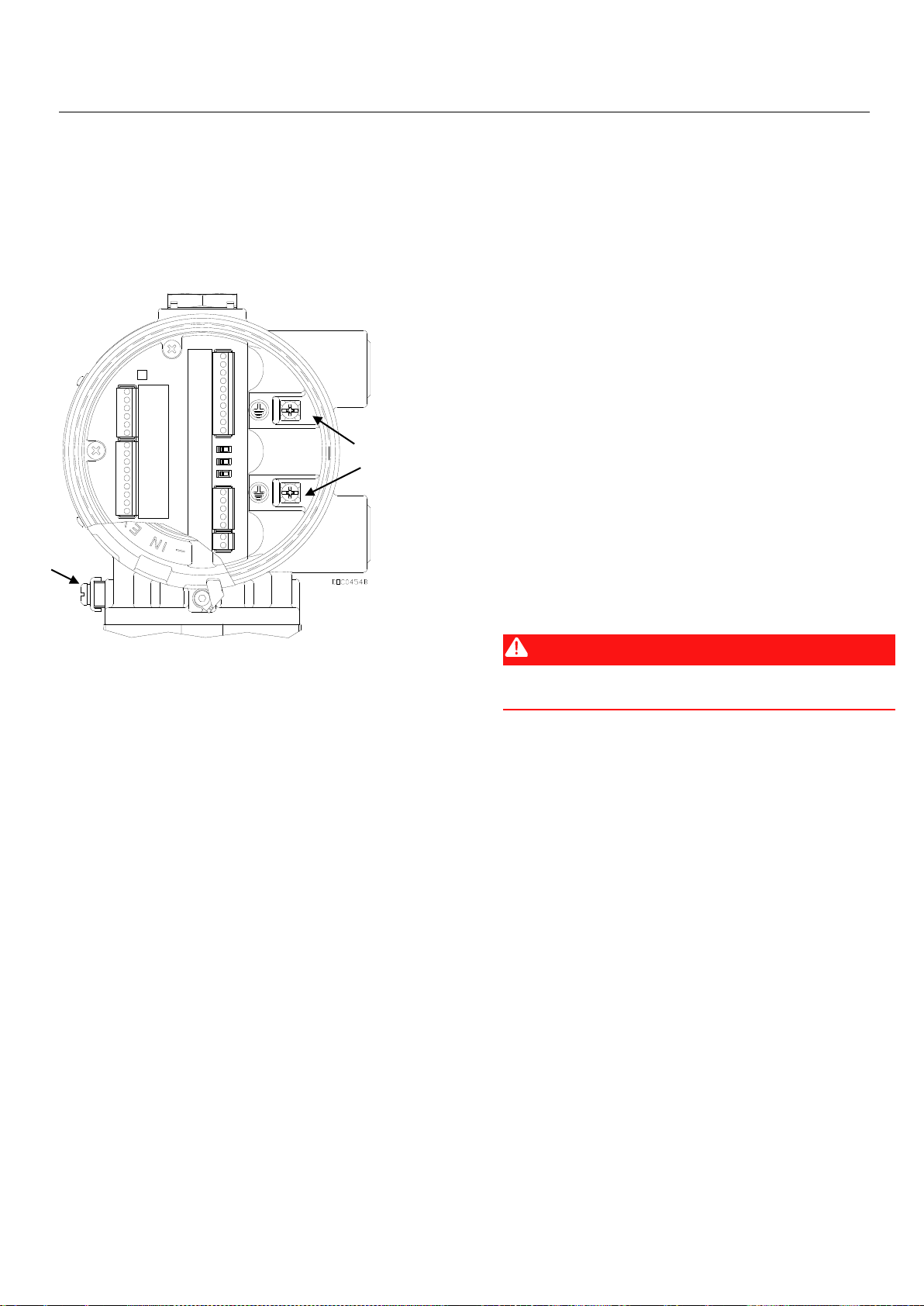
Instructies voor veilig gebruik – Emerson FloBoss 104 Flow Manager
Onderdeelnr. D301733X012
Februari 2018
www.Emerson.com/RemoteAutomation 3
NB De Rosemount-buisinstallatieset is niet geschikt
voor de roestvaststalen behuizing. De klant dient zelf
voor geschikte montage te zorgen.
▪ Rechtstreekse montage op een meterbehuizing.
4. De FloBoss moet goed worden geaard. De FloBoss 104
heeft één aardschroef op de buitenkant van de behuizing
en twee aardschroeven in de behuizing. Zie Afbeelding 2.
A
Interne aardschroeven
B
Externe aardschroef
Afbeelding 2. Achterkant van FloBoss 104
(met klemmenbord)
Door een correcte aarding van de FloBoss 104 wordt het
effect van elektrische ruis gereduceerd en wordt het
apparaat beschermd tegen blikseminslag. De FloBoss
beschikt over bescherming tegen blikseminslag voor
geïntegreerde veldbedradingsingangen en -uitgangen.
Installeer een overspanningsbeveiliger op de serviceafsluiter
op systemen met gelijkspanningsvoeding om de
geïnstalleerde apparatuur te beschermen tegen
blikseminslag en spanningsschommelingen. U kunt ook
overwegen een telefoonoverspanningsbeveiliging te
installeren voor de optionele kaart voor
inbelmodemcommunicatie.
Alle aardverbindingen moeten maximaal een staaf- of
roosterimpedantie van 25 ohm hebben, zoals gemeten met
een aardtester. De aardingsgeleider mag een maximale
weerstand hebben van 1 ohm tussen het aardpunt op de
FloBoss-behuizing en de aardingsstaaf of -rooster.
Als de impedantie tussen de leiding en het massapunt
groter is dan 2 ohm, moet de FloBoss elektrisch geïsoleerd
worden en moet er een aardingsstaaf of
aardingsroostersysteem worden geïnstalleerd.
Voor de I/O-signaalbedrading wordt een geïsoleerde,
afgeschermde, getwiste, tweeaderige kabel aanbevolen.
De getwiste twee aders en de afscherming beperken door
elektromagnetische storingen, radiofrequentiestoringen
en overgangsstromen veroorzaakte foutsignalen tot een
minimum.
5. De FloBoss moet worden aangesloten op de stroom,
de I/O-instrumenten en de communicatieapparatuur. Alle
externe aansluitingen, of veldklemmen, bevinden zich op
het klemmenbord. Op het klemmenbord kan bekabeling
tot maximaal 1,29 mm (16 AWG) worden gebruikt.
De connectors op het klemmenbord van de FloBoss zijn
drukklemmen. De klem voor de ingangsspanning (CHG+ /
CHG–) heeft een verwijderbare connector en hiervoor kan
bekabeling tot maximaal 1,29 mm (16 AWG) worden
gebruikt. In alle gevallen moeten de aansluitingen als volgt
worden gemaakt: strip het uiteinde van de ader (max. 6
mm), steek het gestripte uiteinde van de ader in onder het
klemplaatje onder de aansluitschroef en draai dan de schroef
aan tot 0,25 Nm.
De toegang tot de bedradingsaansluitingen wordt via de
veldbedradingsingangen verkregen. De meegeleverde
metalen blindstoppen moeten op hun plaats blijven zitten in
ongebruikte bedradingsingangen om de drukvastheid van de
behuizing te handhaven. Als deze stoppen om enige reden
worden vervangen, mogen er uitsluitend gecertificeerde
pluggen of draadadapters worden gebruikt die voldoen aan
de productnormen of deze overschrijden.
GEVAAR
De verbindingsschroeven niet te strak aandraaien.
OPMERKINGEN: Controleer of de polen correct zijn
aangesloten vóór de stroom wordt
ingeschakeld.
Er dient zo min mogelijk ongeïsoleerde ader vrijgelaten te
worden om kortsluiting te voorkomen. Laat de draden bij
de aansluitingen iets langer om trekbelasting te
voorkomen.
De FloBoss 104 accepteert ingangsvoltages van
8,0 volt tot 28 volt op de laadklemmen (CHG+ / CHG-)
zonder externe stroombeperking (de interne
stroombeperking is 200 mA).
De aansluitklemmen zijn voorzien van het opschrift CHG+
voor een positieve elektrische aansluiting en CHG- voor een
negatieve elektrische aansluiting op een label op het paneel
met de aansluitklemmen. Zie Afbeelding 3.
A
B
Page 52

Instructies voor veilig gebruik – Emerson FloBoss 104 Flow Manager
Onderdeelnr. D301733X012
Februari 2018
4 www.Emerson.com/RemoteAutomation
Afbeelding 3. Klemmenbord
6. De FloBoss 104 wordt verzonden met de
NORM/RESET-jumper in de positie NORM en de ON/OFFjumper in de positie OFF.
Stroom toevoeren aan de FloBoss 104:
▪ Draai de kapklem aan de onderkant van de eindkap aan
de voorkant (LCD-einde) los. Zie Afbeelding 4.
Afbeelding 4. Kapklem
▪ Schroef het deksel van de eindkap aan de voorkant
los.
▪ Zet de spanningsjumper (bevindt zich op de LCD
indien geïnstalleerd, of op J1 op het acculaderpaneel)
op ON. Zie Afbeelding 5 en Afbeelding 6.
A
NORM/RESET-jumper
B
ON/OFF-jumper
Afbeelding 5. Voorkant van FloBoss 104 (met LCD)
▪ Plaats het deksel van de eindkap aan de voorkant (aan de
LCD-kant) en de kapklem terug.
Nadat de FloBoss 104 de diagnose bij het opstarten
(controle van RAM en andere inwendige functies) heeft
voltooid, geeft het optionele LCD-scherm de datum en tijd
weer om aan te geven dat de FloBoss een geldige
resetroutine heeft uitgevoerd. Als de LCD niet aan gaat,
voer dan een probleemoplossing uit om mogelijke
oorzaken vast te stellen (zie stap 9).
A
ON/OFF-jumper
Afbeelding 6. Voorkant van FloBoss 104 (zonder LCD)
7. De FloBoss 104 moet worden geconfigureerd voordat
deze wordt gekalibreerd en in werking wordt gesteld. De
configuratie moet worden uitgevoerd met de ROCLINK 800software, die op een pc draait. De pc wordt normaliter
verbonden met de LOI-poort van de flowcomputer om
configuratiegegevens over te dragen naar de FloBoss 104,
B
A
A
Page 53
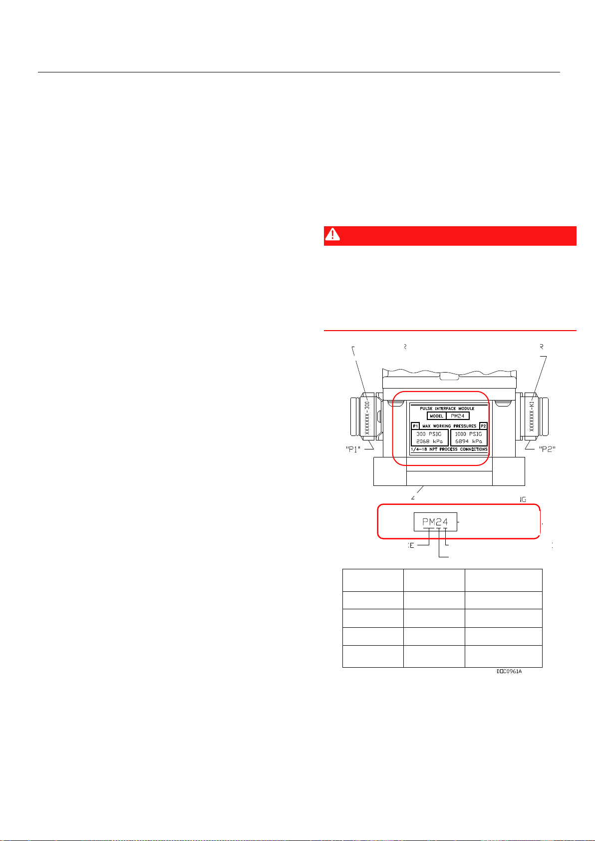
Instructies voor veilig gebruik – Emerson FloBoss 104 Flow Manager
Onderdeelnr. D301733X012
Februari 2018
www.Emerson.com/RemoteAutomation 5
hoewel een groot deel van de configuratie offline kan worden
uitgevoerd en later naar de FloBoss kan worden geladen.
De firmware van de FloBoss bevat standaardparameters.
Als de standaardinstelling acceptabel is voor uw
toepassing, kan deze ongewijzigd worden gelaten. Voer
aanpassingen aan de FloBoss uit met de
configuratiesoftware. Zie de Gebruiksaanwijzing voor
ROCLINK 800-configuratiesoftware (onderdeel
D301159X012).
8. Bij de kalibratieroutine kan 5-puntskalibratie worden
gebruikt, waarbij de drie middelste punten in willekeurige
volgorde kunnen worden gekalibreerd. De lage of
nullezing wordt eerst gekalibreerd, gevolgd door de hoge
of volledigeschaallezing. De drie tussenliggende punten
kunnen daarna desgewenst worden gekalibreerd. De
analoge ingangen voor diagnose - logisch voltage (E1),
accuvoltage (E2) en printplaat/accutemperatuur (E5) - zijn
niet ontworpen om te worden gekalibreerd.
Als de optionele I/O-afsluitpunten zijn geïnstalleerd, kan
de analoge ingang worden gekalibreerd met de ROCLINK
800-software.
De geïntegreerde ingangen waarvoor de 5-puntskalibratie
kan worden gebruikt, zijn:
▪ Verschildruk op AI-punt A1.
▪ Statische druk op AI-punt A2.
▪ RTD-temperatuur op AI-punt A3.
Deze ingangen worden toegewezen aan de eerste drie
analoge ingangspunten. De kalibratieprocedure voor deze
ingangen staat beschreven in de Gebruiksaanwijzing voor
ROCLINK 800-configuratiesoftware (onderdeel
D301159X012).
9. Bepaal om problemen met de FloBoss 104 op te lossen
altijd eerst of het probleem door de configuratie of door de
hardware wordt veroorzaakt. Controleer de configuratie in
de ROCLINK 800-software om eventuele incorrecte
instellingen op te sporen. Controleer de hardware op
beschadigingen. Controleer de klemmenborden op verkeerd
gemaakte aansluitingen.
Als u problemen ondervindt met de FloBoss 104 die
softwaregerelateerd lijken te zijn, probeer dan de FloBoss
te resetten met een warme start, een koude start of een
jumperreset.
Als u problemen ondervindt die met de hardware te
maken lijken te hebben, controleert u de bekabeling. Als u
daarna nog steeds problemen ondervindt, vraag dan
toestemming aan het plaatselijke verkoopkantoor voor
retourzending.
Tijdens de werking kan de FloBoss 104 lokaal of op afstand
worden gemonitord (om actuele en historische gegevens
te bekijken of op te halen). De lokale monitoring wordt
uitgevoerd door te kijken op het LCD-paneel zoals
beschreven in hoofdstuk 2, of met de ROCLINK 800-
software op een pc die is aangesloten via de LOI-poort. De
monitoring op afstand wordt uitgevoerd via Comm 1 of
Comm 2 van de FloBoss met ROCLINK 800-software of via
het hostsysteem. Zie Afbeelding 8 voor de
communicatieaansluitingen.
10. Om de FloBoss 104 buiten gebruik te stellen,
ontkoppelt u de voeding van de eenheid en haalt u
vervolgens alle externe draadverbindingen los. Verwijder
de gasleidingen. Verwijder ten slotte de behuizing van de
FloBoss van de leidingsteun of meetflens. De FloBoss kan
voor transport in een doos worden geplaatst.
GEVAAR
Wees voorzichtig bij het verwijderen van de gasleidingen
van de FB104. Gebruik één sleutel om te voorkomen dat
de sensoraansluiting beweegt, en gebruik een tweede
sleutel om de gasleiding te ontkoppelen. Als de sensor
draait, kan dat de interne bedrading beschadigen.
Afbeelding 7. Pulsinterfacebehuizing FB104
Let bij het aansluiten van gasdrukleidingen op de
optionele pulsinterfacemodule op de maximale
werkdruklimieten voor de individuele P1- en P2-sensors op
basis van het modelnummer van de module. Afbeelding 7
toont bijvoorbeeld een module model PM24 met de
bereikwaarden voor sensor P1 (300 psig/2068 kPa)
en P2 (1000 psig/6894 kPa).
MARKERING
SENSOR P1
MARKERING
SENSOR P2
OPTIONELE METERBEHUIZING
MODELNR. MODULE
(VOORBEELD
AFGEBEELD)
PULSINTERFACE
MODULESERIE
BEREIKCODE SENSOR P2
BEREIKCODE SENSOR P1
BEREIKCODE
MAX
BEDRIJFSDRUK
SENSORMARKERING
0
PLUG
N.v.t.
1
100 psig
689 kPa
XXXXXX – 100
2
300 psig
2068 kPa
XXXXXX – 300
4
1000 psig
6094 kPa
XXXXXX – K1
Page 54

Instructies voor veilig gebruik – Emerson FloBoss 104 Flow Manager
Onderdeelnr. D301733X012
Februari 2018
6 www.Emerson.com/RemoteAutomation
A
Naamplaatje FloBoss 104
B
Label DVS-sensor
Afbeelding 8. Afmetingen FloBoss 104
A
½ - 14 NPT ingangen veldbedrading
Afbeelding 9. Montagestijlen FloBoss 104
A
B
A
Page 55

Instructies voor veilig gebruik – Emerson FloBoss 104 Flow Manager
Onderdeelnr. D301733X012
Februari 2018
Ga voor klantenservice en ondersteuning
naar www.Emerson.com/SupportNet.
Internationaal hoofdkantoor,
Noord-Amerika en Latijns-Amerika:
Emerson Automation Solutions
Remote Automation Solutions
6005 Rogerdale Road
Houston, TX 77072, VS
T +1 281 879 2699 | F +1 281 988 4445
www.Emerson.com/RemoteAutomation
© 2015 - 2018 Remote Automation Solutions, een afdeling van Emerson Automation
Solutions. Alle rechten voorbehouden.
Deze publicatie dient uitsluitend ter informatie. Hoewel we uiterste zorg hebben besteed aan
de nauwkeurigheid, kunnen er geen rechten of garanties, expliciet of impliciet, met betrekking
tot de producten of diensten die erin beschreven worden, of het gebruik of de toepasbaarheid
ervan, aan worden ontleend. Remote Automation Solutions (RAS) behoudt zich het recht voor
de ontwerpen of specificaties van deze producten op elk moment en zonder kennisgeving aan
te passen of te verbeteren. Alle verkooptransacties vallen onder de voorwaarden van RAS,
welke op verzoek beschikbaar worden gesteld. RAS aanvaardt geen verantwoordelijkheid voor
juiste selectie, juist gebruik en juist onderhoud van welk product dan ook; deze
verantwoordelijkheid berust uitsluitend bij de koper en/of eindgebruiker.
Europa:
Emerson Automation Solutions
Remote Automation Solutions
Unit 8, Waterfront Business Park
Dudley Road, Brierley Hill
Dudley UK DY5 1LX
T +44 1384 487200 | F +44 1384 487258
Midden-Oosten en Afrika:
Emerson Automation Solutions
Remote Automation Solutions
Emerson FZE
P.O. Box 17033
Jebel Ali Free Zone – South 2
Dubai V.A.E.
T +971 4 8118100 | F +971 4 8865465
Azië-Pacific:
Emerson Automation Solutions
Remote Automation Solutions
1 Pandan Crescent
Singapore 128461
T +65 6777 8211 | F +65 6777 0947
Remote Automation Solutions
Page 56

Page 57
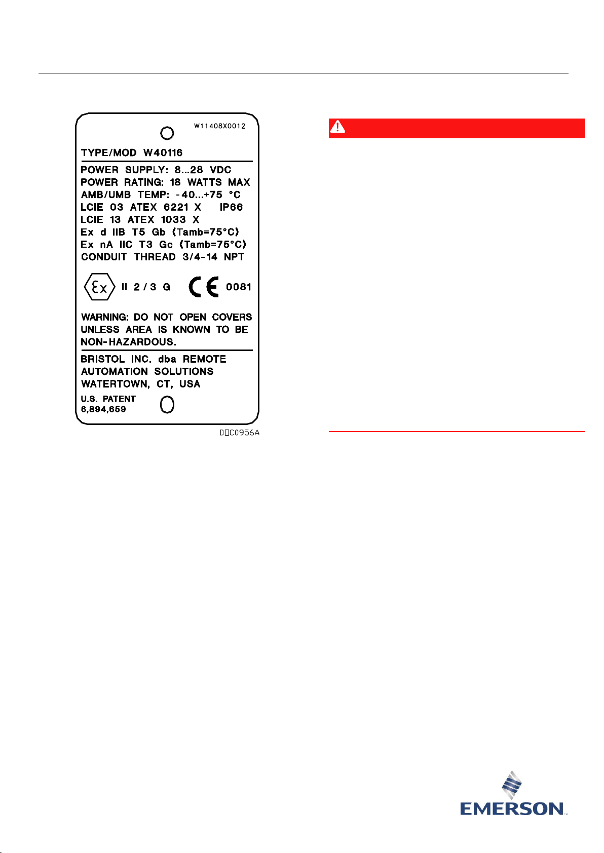
Instrucciones para un uso seguro – Administrador de caudal Emerson FloBoss 104
Parte D301733X012
Febrero de 2018
Soluciones de automatización remota
Administrador de caudal Emerson FloBoss™ 104
Figura 1. Placa de identificación del administrador de caudal
FloBoss 104 (se muestra la versión ATEX)
Use esta hoja de instrucciones con el Manual de instrucciones
del administrador de caudal FloBoss 103 y FloBoss104 (Parte
D301153X012). Para conocer todas las precauciones y las
descripciones de instalación y los procedimientos de
solución de problemas, consulte el manual.
El administrador de caudal FloBoss 104 con las
aprobaciones incombustibles de ATEX o IECEx se puede
pedir con el módulo de interfaz de pulso (PIM),
comunicaciones EIA-232 (RS-232) o comunicaciones de
módem de acceso telefónico.
Condiciones especiales para un uso seguro de
FloBoss 104
▪ Temperatura ambiente operativa: -40 °C a +75 °C
▪ Asegúrese de que la transferencia térmica del fluido
no sobrecaliente el equipo hasta alcanzar una
temperatura por la que ocurra la combustión
espontánea del gas circundante.
Declaración de conformidad
Por la presente, Remote Automation Solutions declara que
el producto FloBoss 104 cumple con los requisitos
esenciales y otras provisiones relevantes de las directivas
europeas 2004/108/EC (EMC), 94/9/EC (ATEX) y 97/23/EC
(PED) según corresponda.
PELIGRO
Al instalar unidades en un área peligrosa, asegúrese de
que todos los componentes seleccionados para la
instalación estén diseñados para su uso en este tipo de
entornos. La instalación y el mantenimiento deben
llevarse a cabo sólo cuando se tenga la seguridad de que el
área no es peligrosa. La instalación en un área peligrosa
podría ocasionar lesiones personales o daños materiales.
Siempre apague la alimentación a FloBoss antes
de intentar cualquier tipo de cableado. El cableado de
equipos con alimentación conectada podría ocasionar
lesiones personales o daños materiales.
Para evitar daños en los circuitos al trabajar dentro de la
unidad, utilice las debidas precauciones contra descargas
electrostáticas, como el uso de una pulsera antiestática
conectada a tierra.
No abra las cubiertas a menos que se sepa que el área no
es peligrosa.
Conectar el FB104 a una fuente de alimentación continua
de alto voltaje sin quitar el módulo del cargador de batería
podría causar una sobrecarga de batería y una falla.
Consulte la Sección 3.5.1, Posibilidad de sobrecarga en el
Manual de instrucciones del administrador de caudal FloBoss
103 y 104 (parte D301153X012).
Page 58

Instrucciones para un uso seguro – Administrador de caudal Emerson FloBoss 104
Parte D301733X012
Febrero de 2018
2 www.Emerson.com/RemoteAutomation
Especificaciones
ALIMENTACIÓN
Entrada de carga de alimentación externa: 8-28 V cc,
protección contra la inversión de polaridad.
Corriente de entrada: 10-15 mA nominal. 20 mA al
100 % del ciclo de trabajo (no se incluye la carga de la
batería).
CARCASA
Carcasa y tapa: aleación de aluminio fundido con
enchapado Iridite y pintura. Versión de acero
inoxidable (CF8M) disponible.
CARACTERÍSTICAS AMBIENTALES
Temperatura ambiente operativa: -40 a +75 C.
Pantalla LCD: -20 a +75 C.
Temperatura de almacenamiento: -50 a +85 C.
Humedad de operación: 5 a 95 %, sin condensación.
PESO
4,30 kg (9,5 lb) (aluminio)
APROBACIONES:
ATEX Versión (a prueba de llamas y tipo n)
Evaluado según las normas de aprobación:
(A prueba de llamas) (Tipo n)
EN 60079-0 (2012) EN 60079-0 (2012)
EN 60079-1 (2007) EN 60079-15 (2010)
IEC 60529 IEC 60529
Certificado por LCIE como Modelo W40116.
ATEX Cert LCIE 03ATEX6221 X/06
ATEX Cert LCIE 13ATEX1033 X/01
Marcas de productos para ubicaciones peligrosas:
Ex d IIB T5 Gb (-40°C ≤ T
amb
≤ +75°C), IP66
Ex nA IIB T3 Gc (-40°C ≤ T
amb
≤ +75°C), IP66
II 2/3 G. 0081
Especificaciones
IECEx Versión (a prueba de llamas y tipo n)
Evaluado según las normas de aprobación:
IEC 60079-0 (2011)
IEC 60079-1 (2007)
IEC 60079-15 (2010)
IEC 60529
Certificado por CSA como Modelo W40149.
IEC Cert IECEx LCI 08.0039 (A prueba de llamas)
IEC Cert IECEx LCI 08.0015 (Tipo n)
Marcas de productos para ubicaciones peligrosas:
Ex d IIB T5 Gb (-40°C ≤ T
amb
≤ +75°C), IP66
Ex nA IIC T3 Gc (-40°C ≤ T
amb
≤ +75°C), IP66.
IECEx Versión (Tipo n únicamente)
Evaluado según las normas de aprobación:
IEC 60079-0 (2011)
IEC 60079-15 (2010)
IEC 60529
Certificado por CSA como Modelo W40150.
IEC Cert IECEx LCI 08.0015 (Tipo n)
Marcas de productos para ubicaciones peligrosas:
Ex nA IIC T3 Gc (-40°C ≤ T
amb
≤ +75°C), IP66.
Se requieren las siguientes herramientas para la
instalación, el mantenimiento y la solución de problemas:
▪ Computadora personal con Microsoft® Windows® 7,
Windows 8.1 o Windows 10 y el software de
configuración Emerson Field Tools (que proporciona
el software de configuración ROCLINK™ 800).
▪ Software de configuración ROCLINK 800.
▪ Destornillador Phillips (cruciforme).
▪ Destornillador de cabeza plana.
▪ Llave hexagonal (M4).
1. El FloBoss 104 se recibe en una caja. Retírelo de la
caja.
2. Busque una ubicación adecuada para el FloBoss 104.
Cuando elija un lugar de instalación, asegúrese de revisar
todos los espacios vacíos. Proporcione suficiente espacio
para el cableado y el mantenimiento. El indicador de LCD
opcional debe ser visible y accesible para el operador in
situ. Vea la Figura 8.
3. El montaje del FloBoss 104 se puede lograr usando
uno de los siguientes métodos:
▪ Soporte de tubería montado en un estante de 2 pulg.
Use el juego de montaje de tubería Rosemount de 2"
(50 mm) (con tubería de impulso que conecte el
FloBoss 104 al tramo de medidor). Asegúrese de que
el soporte de tubería cumpla con todos los requisitos
de peso y que la instalación se encuentre en
Page 59

Instrucciones para un uso seguro – Administrador de caudal Emerson FloBoss 104
Parte D301733X012
Febrero de 2018
www.Emerson.com/RemoteAutomation 3
conformidad con los códigos de construcción locales.
Vea Figura 9.
Nota: El juego de montaje de tubería Rosemount no
es adecuado para la carcasa de acero inoxidable. Los
clientes deben proporcionar un montaje adecuado.
▪ Montaje directo en una carcasa de medidor.
4. El FloBoss se debe conectar a tierra correctamente.
El FloBoss 104 tiene un tornillo de conexión a tierra afuera
de la carcasa y dos tornillos de conexión a tierra dentro de
la carcasa. Vea Figura 2.
A
Tornillo de conexión a tierra interna
B
Tornillo de conexión a tierra externa
Figura 2. Unidad final del FloBoss 104
(con placa de terminación)
La puesta a tierra adecuada del FloBoss 104 contribuye a
reducir los efectos del ruido eléctrico en el funcionamiento
de la unidad y la protege contra rayos. El FloBoss proporciona
protección contra rayos para el cableado de campo integrado
para las entradas y salidas. Instale un dispositivo de
protección contra sobretensiones en la desconexión de
servicio en sistemas de voltaje de CC para proteger el equipo
instalado contra rayos y sobretensiones. También podría
tener en cuenta un protector contra sobretensiones
telefónicas para la tarjeta de comunicaciones de módem de
acceso telefónico opcional.
Todas las conexiones a tierra deben tener una varilla a
tierra o rejilla de tierra con impedancia de 25 ohmios o
menos, medida con un probador de sistemas de tierra. El
conductor de tierra debe tener una resistencia de 1 ohmio
o menos entre la conexión a tierra de la carcasa del FloBoss
y la varilla o la rejilla de tierra.
Si la impedancia de la tubería a tierra es mayor que 2
ohmios, la instalación del FloBoss debe aislarse
eléctricamente y se debe instalar una varilla o un sistema
de rejilla a tierra.
Para el cableado de señal de E/S se recomienda un cable
aislado, blindado y en par trenzado. El par trenzado y el
blindaje reducen al mínimo los errores de señal causados
por EMI (interferencia electromagnética), RFI
(interferencia de radiofrecuencia) y transitorios.
5. Conecte la alimentación del FloBoss, los dispositivos
de E/S y los dispositivos de comunicación. Las conexiones
externas, o los terminales de campo, se encuentran en la
placa de terminación. El bloque de terminales acepta
cables de hasta 1,29 mm (16 AWG) de tamaño.
Los conectores de la placa de terminación del FloBoss usan
terminales de compresión. La terminación de alimentación
de entrada (CHG+/CHG-) usa un conector extraíble y
admite un cableado de hasta 1,29 mm (16 AWG) de
tamaño. En todos los casos, haga las conexiones pelando el
extremo del cable (6 mm como máximo), insertando el
extremo pelado en el sujetador debajo del tornillo de
terminación y, luego, ajustando el tornillo a 0,25 N-m.
El acceso a las conexiones del cableado se hace por medio
de las entradas de cableado de campo. Los tapones de la
tubería de metal deben permanecer en el lugar, en las
entradas de cableado no usadas con el fin de mantener la
integridad a prueba de incendios de la carcasa. Si por alguna
razón se reemplazan estos tapones, solo instale tapones
certificados o adaptadores roscados que cumplan con las
clasificaciones del producto o las superen.
PELIGRO
No ajuste demasiado el par de los tornillos del conector.
NOTAR: Revise la polaridad de la alimentación de entrada
antes de encender la alimentación.
Los cables insertados deben tener un mínimo de cable
pelado expuesto para evitar cortocircuitos. Permita que
haya algo de espacio suficiente cuando haga las conexiones
para evitar la presión.
El FloBoss 104 acepta los voltajes de entrada desde
8,0 voltios hasta 28 voltios en los terminales de carga
(CHG+/CHG-) sin límite de corriente externa (el límite
de corriente interna es 200 mA).
En el tablero de terminaciones, existe una etiqueta que
denomina los terminales: CHG+ para la conexión positiva
de la alimentación y CHG- para la negativa. Vea Figura 3.
A
B
Page 60

Instrucciones para un uso seguro – Administrador de caudal Emerson FloBoss 104
Parte D301733X012
Febrero de 2018
4 www.Emerson.com/RemoteAutomation
Figura 3. Placa de terminación
6. El FloBoss 104 se envía con el puente de NORM/RESET
(Normal/Reinicio) en la posición NORM, y el puente de
ON/OFF (Encendido/Apagado) en la posición OFF.
Para encender el FloBoss 104:
▪ Destornille el sujetador de la cubierta en la base de
la tapa del extremo delantero (extremo de LCD).
Consultar la Figura 4.
Figura 4. Conjunto de sujetador de cubierta
▪ Destornille la cubierta de la tapa del extremo
delantero.
▪ Coloque el puente de alimentación (ubicado en el LCD
si está instalado o en J1 en el tablero del cargador de la
batería) en la posición de encendido. Consulte Figura 5
y Figura 6.
A
Puente de NORM/RESET
B
Puente de ON/OFF
Figura 5. Unidad delantera del FloBoss 104 (con LCD)
▪ Destornille la cubierta de la tapa del extremo
delantero (el correspondiente a la pantalla LCD) y el
sujetador de la cubierta.
Una vez que el FloBoss 104 haya finalizado los
diagnósticos correspondientes al arranque (verificación de
RAM, así como otras verificaciones internas), la pantalla
LCD opcional muestra la fecha y la hora, lo que indica que
el FloBoss ha finalizado una secuencia valida de
reinicialización. Si la pantalla LCD no se enciende, lea la
solución de problemas para buscar las causas posibles (vea
el Paso 9).
A
Puente de ON/OFF
Figura 6. Unidad delantera del FloBoss 103 (sin LCD)
7. El FloBoss 104 se debe configurar antes de que se
calibre y se ponga en funcionamiento. La configuración se
debe realizar con el software ROCLINK 800, que se ejecuta
en una computadora. La computadora normalmente está
B
A
A
Page 61

Instrucciones para un uso seguro – Administrador de caudal Emerson FloBoss 104
Parte D301733X012
Febrero de 2018
www.Emerson.com/RemoteAutomation 5
conectada a un puerto de LOI de la computadora de
caudal para transferir los datos de configuración al FloBoss
104, aunque la mayoría de la configuración se puede
hacer fuera de línea y, luego, cargarla al FloBoss.
Los valores predeterminados para todos los parámetros
se encuentran en el firmware del FloBoss. Si los valores
predeterminados son correctos para su aplicación,
se pueden dejar así. Realice los ajustes en el FloBoss a través
del software de configuración. Consulte el Manual de
usuario del software de configuración ROCLINK 800 (Parte
D301159X012).
8. Las rutinas de calibración admiten una calibración de 5
puntos, con los tres puntos intermedios calibrados en
cualquier orden. Calibre primero la lectura inferior o cero,
seguida por la lectura superior o de escala completa. Los
tres puntos intermedios se pueden calibrar a
continuación, si lo desea. Las entradas analógicas de
diagnóstico, voltaje lógico (E1), voltaje de batería (E2) y
temperatura de placa/batería (E5), no están diseñadas
para calibrarse.
Con los puntos de terminación de E/S opcionales, calibre la
entrada analógica con el software ROCLINK 800.
Las entradas incorporadas que se admiten con la
calibración de 5 puntos son:
▪ Presión diferencial ubicada en AI Point A1.
▪ Presión estática ubicada en AI Point A2.
▪ Temperatura de RTD ubicada en AI Point A3.
Estas entradas se asignan a los primeros tres puntos de
entrada analógica. El procedimiento de calibración para
estas entradas se describe en el Manual de usuario del
software de configuración ROCLINK 800 (parte
D301159X012).
9. Para solucionar problemas con el FloBoss 104,
identifique si el problema es con la configuración o con el
hardware. Revise la configuración en el software ROCLINK
800 para identificar cualquier configuración incorrecta.
Inspeccione si hay daños en el hardware. Inspeccione las
placas de circuitos para encontrar errores de ubicación de
conexiones.
Si tiene problemas con el FloBoss 104 que parezcan estar
relacionados con el software, trate de restablecer el
FloBoss con un inicio en caliente, un inicio en frío o un
restablecimiento de puente.
Si tiene problemas que parezcan estar relacionados con el
hardware, revise el cableado. Si todavía tiene problemas,
comuníquese con la oficina de ventas local para obtener
una autorización de devolución.
Durante el funcionamiento, es posible monitorear al
FloBoss 104 (para ver o recuperar los datos actuales e
históricos) ya sea de manera local o remota. El monitoreo
local se logra al observar el panel LCD detallado en la
Sección 2 o al usar el software ROCLINK 800 en una
computadora conectada a través del puerto de LOI. El
monitoreo remoto se realiza mediante la opción Comm 1
o Comm 2 del FloBoss con el software ROCLINK 800 o el
sistema host. Consulte Figura 8 para conocer las
terminaciones de comunicaciones.
10. Para hacer que el FloBoss 104 deje de funcionar,
desconecte la alimentación de la unidad y, luego, quite
todas las conexiones externas del cableado. Quite las líneas
de gas. Finalmente, retire la carcasa del FloBoss del soporte
de tubería o la placa de orificio. Se debe colocar el FloBoss
en una caja para su transporte.
PELIGRO
Tenga cuidado al quitar las líneas de gas del FB104. Use
una llave para evitar que el conector del sensor se mueva y
use una segunda llave para desconectar la línea de gas. Si
el sensor gira, se dañará el cableado interno.
Figura 7. Carcasa de interfaz de pulso del FB104
Cuando conecte líneas de presión de gas al módulo de
interfaz de pulso opcional, tenga en cuenta los límites
máximos de presión de funcionamiento en los sensores P1
y P2 individuales según el número de modelo del módulo.
Por ejemplo, la Figura 7 muestra un módulo modelo PM24
con sus rangos de sensor P1 (300 PSIG/2068 kPa) y P2
(1000 PSIG/6894 kPa).
MARCA DE
SENSOR P1
MARCA DE
SENSOR P2
CARCASA DE MEDIDOR OPCIONAL
N.° DE MODELO DEL
MÓDULO
(SE MUESTRA UN EJEMPLO)
INTERFAZ DE PULSO
SERIES DE MÓDULO
CÓDIGO DE RANGO DEL SENSOR P2
CÓDIGO DE RANGO DEL SENSOR P1
CÓDIGO DE
RANGO
PRESIÓN MÁX. DE
FUNCIONAMIENTO
MARCA DEL
SENSOR
0
ENCHUFE
N/D
1
100 PSIG
689 kPo
XXXXXXX – 100
2
300 PSIG
2068 kPo
XXXXXXX – 300
4
1000 PSIG
6894 kPo
XXXXXXX – K1
Page 62

Instrucciones para un uso seguro – Administrador de caudal Emerson FloBoss 104
Parte D301733X012
Febrero de 2018
6 www.Emerson.com/RemoteAutomation
A
Placa de identificación del FloBoss 104
B
Etiqueta del sensor de DVS
Figura 8. Dimensiones del FloBoss 104
A
Entradas de cableado de campo de 3/4-14 NPT
Figura 9. Estilos de montaje del FloBoss 104
A
Page 63

Instrucciones para un uso seguro – Administrador de caudal Emerson FloBoss 104
Parte D301733X012
Febrero de 2018
Para recibir servicio al cliente y soporte técnico,
visite www.Emerson.com/SupportNet.
Oficinas centrales,
Norteamérica y Latinoamérica:
Emerson Automation Solutions
Remote Automation Solutions
6005 Rogerdale Road
Houston, TX 77072 EE. UU.
Tel. +1 281 879 2699 | Fax +1 281 988
4445
www.Emerson.com/RemoteAutomation
© 2015 – 2018 Remote Automation Solutions, una unidad comercial de Emerson Automation
Solutions. Reservados todos los derechos.
Esta publicación tiene fines exclusivamente informativos. Aunque se han realizado todos los esfuerzos
para garantizar su exactitud, esta publicación no incluye garantías, explícitas o implícitas, incluyendo
los productos o servicios descritos o su uso o aplicación. Remote Automation Solutions se reserva el
derecho de modificar o mejorar los diseños o especificaciones de dichos productos en cualquier
momento, sin previo aviso. Todas las ventas están regidas por los términos y condiciones de RAS, los
cuales se encuentran disponibles si se solicitan. RAS no acepta responsabilidad de la selección, el uso y
el mantenimiento correctos de cualquier producto, que corresponde exclusivamente al comprador
y/o al usuario final.
Europa:
Emerson Automation Solutions
Remote Automation Solutions
Unit 8, Waterfront Business Park
Dudley Road, Brierley Hill
Dudley UK DY5 1LX
Tel. +44 1384 487200 | Fax +44 1384 487258
Oriente Medio/África:
Emerson Automation Solutions
Remote Automation Solutions
Emerson FZE
P.O. Box 17033
Jebel Ali Free Zone – South 2
Dubái E. A. U.
Tel. +971 4 8118100 | Fax +971 4 8865465
Asia-Pacífico:
Emerson Automation Solutions
Remote Automation Solutions
1 Pandan Crescent
Singapur 128461
Tel. +65 6777 8211| Fax +65 6777 0947
Soluciones de automatización remota
Page 64

 Loading...