

FB3000 Remote Terminal Unit (RTU) Power Supply Module (3PWBLK) and Chassis (3CH08A) Field Installation Guide
Table of contents
 Loading...
Remote Automation Solutions FB3000 Remote Terminal Unit (RTU) Power Supply Module (3PWBLK) and Chassis (3CH08A) Field Installation Guide Manuals & Guides
Page 1

FB3000 RTU Power Supply Module and Chassis Field Installation Guide
D301874X012
FB3000 Remote Terminal Unit (RTU)
Power Supply Module (3PWBLK) and Chassis
(3CH08A)
Field Installation Guide
June 2021
Remote Automation Solutions
Page 2

FB3000 RTU Power Supply Module and Chassis Field Installation Guide
D301874X012
June 2021
Device Safety Considerations
Reading these Instructions
Before operating the device, read these instructions carefully and understand their safety implications. In some situations,
improperly using this device may result in damage or injury. Keep this manual in a convenient location for future reference.
Note that these instructions may not cover all details or variations in equipment or cover every possible situation regarding
installation, operation, or maintenance. Should problems arise that are not covered sufficiently in the text, immediately
contact Customer Support for further information.
Protecting Operating Processes
A failure of this device – for whatever reason -- may leave an operating process without appropriate protection and could result
in possible damage to property or injury to persons. To protect against this, you should review the need for additional backup
equipment or provide alternate means of protection (such as alarm devices, output limiting, fail-safe valves, relief valves,
emergency shutoffs, emergency switches, etc.). Contact Remote Automation Solutions for additional information.
Returning Equipment
If you need to return any equipment to Remote Automation Solutions, it is your responsibility to ensure that the equipment
has been cleaned to safe levels, as defined and/or determined by applicable federal, state and/or local law regulations or
codes. You also agree to indemnify Remote Automation Solutions and hold Remote Automation Solutions harmless from any
liability or damage which Remote Automation Solutions may incur or suffer due to your failure to ensure device cleanliness.
Grounding Equipment
Ground metal enclosures and exposed metal parts of electrical instruments in accordance with OSHA rules and regulations as
specified in Design Safety Standards for Electrical Systems, 29 CFR, Part 1910, Subpart S, dated: April 16, 1981 (OSHA rulings are
in agreement with the National Electrical Code). You must also ground mechanical or pneumatic instruments that include
electrically operated devices such as lights, switches, relays, alarms, or chart drives.
Important: Complying with the codes and regulations of authorities having jurisdiction is essential to ensuring personnel
safety. The guidelines and recommendations in this manual are intended to meet or exceed applicable codes and regulations.
If differences occur between this manual and the codes and regulations of authorities having jurisdiction, those codes and
regulations must take precedence.
Protecting from Electrostatic Discharge (ESD)
This device contains sensitive electronic components which be damaged by exposure to an ESD voltage. Depending on the
magnitude and duration of the ESD, it can result in erratic operation or complete failure of the equipment. Ensure that you
correctly care for and handle ESD-sensitive components.
System Training
A well-trained workforce is critical to the success of your operation. Knowing how to correctly install, configure, program,
calibrate, and trouble-shoot your Emerson equipment provides your engineers and technicians with the skills and confidence
to optimize your investment. Remote Automation Solutions offers a variety of ways for your personnel to acquire essential
system expertise. Our full-time professional instructors can conduct classroom training at several of our corporate offices, at
your site, or even at your regional Emerson office. You can also receive the same quality training via our live, interactive
Emerson Virtual Classroom and save on travel costs. For our complete schedule and further information, contact the Remote
Automation Solutions Training Department at 800-338-8158 or email us at education@emerson.com.
Ethernet Connectivity
This automation device is intended to be used in an Ethernet network which does not have public access. The inclusion of this
device in a publicly accessible Ethernet-based network is not recommended.
Page 3
FB000 RTU Power Supply Module and Chassis Field Installation Guide
DANGER
D301874X012
June 2021
Removing/Replacing the Power Supply Module
The FB3000 supports up to two power supply modules (3PWBLK). If you have two power
modules installed, you can remove either one of them –
operating.
but not both – while the RTU is
EXPLOSION HAZARD: Ensure the area in which you perform this operation is non-hazardous.
Performing this operation in a hazardous area could result in an explosion.
Required Tools
#2 Phillips-head screwdriver
1/4-inch flat head screwdriver
Removing a Power Module
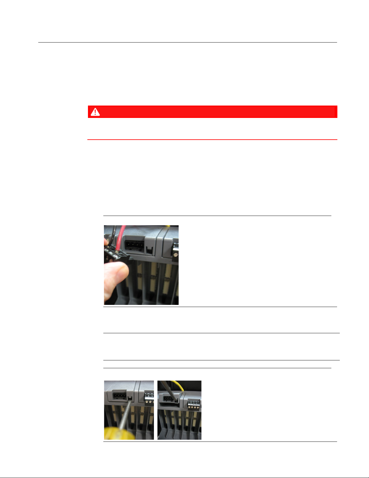
1. Disconnect the terminal block from the power module you want to remove.
Disconnecting the Terminal Block
2. Push a flathead screwdriver into the opening in the lower right of the power module and
rotate the handle of the screwdriver
Note
Do not rotate the handle of the screwdriver downwards; that may pop the cover off the
power module.
Removing Power Module
upwards to rotate the module upwards.
1
Page 4
FB000 RTU Power Supply Module and Chassis Field Installation Guide
DANGER
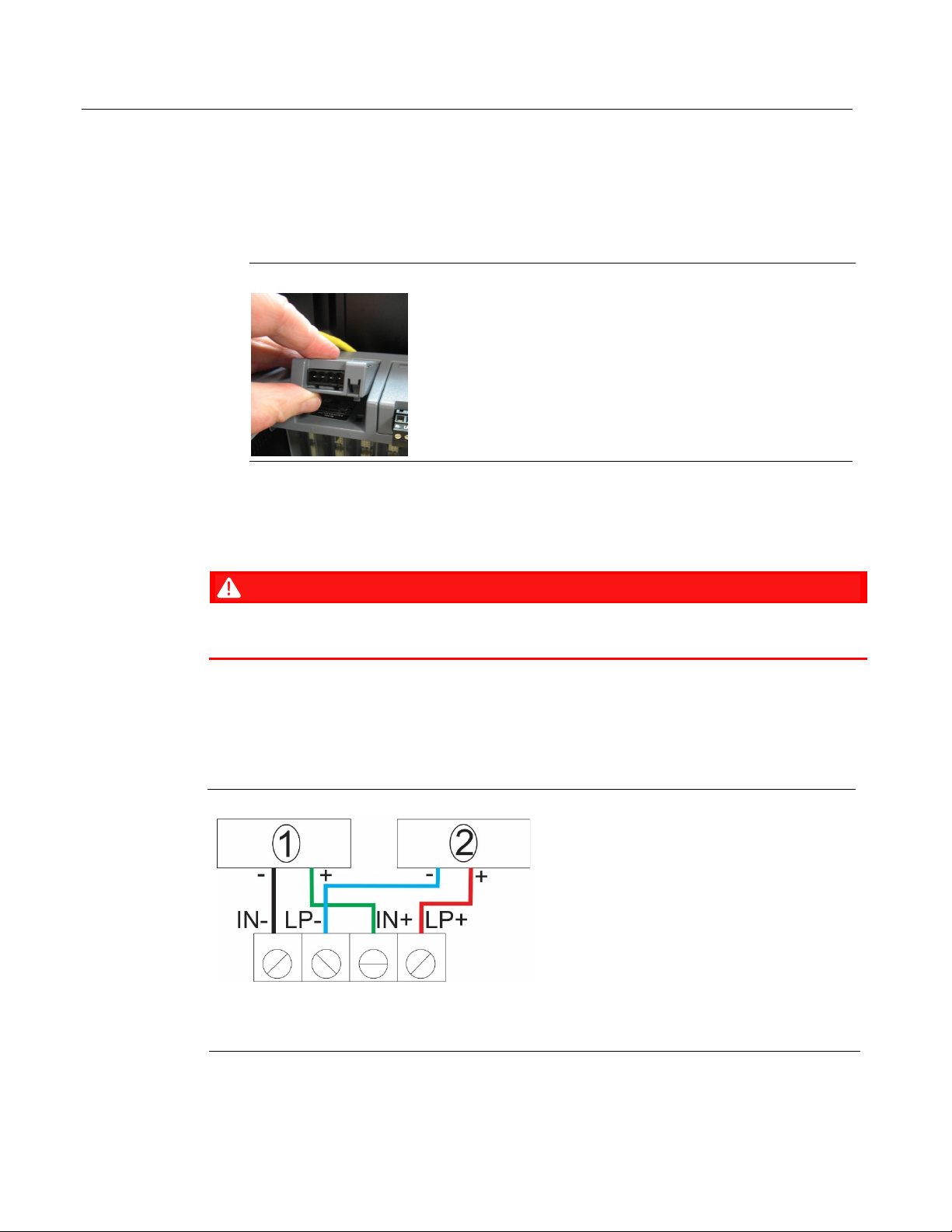
1
Input power from external power supply (power for RTU)
2
Loop power from external power supply (power for field devices)
D301874X012
June 2021
3. Now you can grasp the power module and pull it out.
Replacing a Power Module
1. Press the power module at an angle into the chassis with the tab at the rear end of the
module going into the matching slot of the chassis. Press the module in as you rotate it
down and it snaps into place.
Replacing Power Module
2. Re-attach the terminal block.
Wiring the Power Supply Module
EXPLOSION HAZARD: Ensure the area in which you perform this operation is non-hazardous.
Performing this operation in a hazardous area could result in an explosion.
The FB3000 supports both 12V and 24V power supplies. It accepts DC voltage from 10.5 to 30V;
the amount of power required varies depending upon the options used.
Input power powers the RTU; loop power can power attached field devices. Input power and
loop power do not need to have the same voltage.
External Power Connections
2
Page 5

FB000 RTU Power Supply Module and Chassis Field Installation Guide
DANGER
DANGER
Removing/Replacing the Chassis
The FB3000 supports two chassis versions: 3CHO8C and 3CHO8A. This procedure is the same
regardless of chassis type.
D301874X012
June 2021
Switch the process this RTU controls over to whatever manual/backup system you have.
EXPLOSION HAZARD: Ensure the area in which you perform this operation is non-hazardous.
Performing this operation in a hazardous area could result in an explosion.
1. Back up data in the CPU. See Chapter 5 of the FB3000 RTU Instruction Manual
(D301851X012) for details.
2. Remove power from the FB3000 by disconnecting the terminal blocks from the power
modules. See Removing/Replacing the Power Module for more information.
3. Remove each of the power modules. See Removing/Replacing the Power Module for more
information.
4. While leaving communication cables connected, remove the CPU module from slot 1 by
depressing the orange tabs at the top and bottom of the module, and sliding it out.
Carefully set it aside with any cables still attached.
Removing the CPU Module
5. Leaving wiring connected, use a ¼” slotted blade screwdriver to loosen the captive
fastening screw at the top of the CPU’s personality module and slide the module straight
out of the slot. To avoid confusing it with other personality modules, you can use a rubber
band to attach it to the CPU module you set aside in step 4.
3
Page 6

FB000 RTU Power Supply Module and Chassis Field Installation Guide
D301874X012
June 2021
Removing the Personality Module
6. Going from left to right starting with the second slot in the chassis, remove the first Mixed
I/O module (3MIX12) present by depressing the orange tabs at the top and bottom of the
module, and slide it out. Carefully set it aside.
7. Leaving wiring connected, use a ¼” slotted blade screwdriver to loosen the captive
fastening screw at the top of the personality module for the mixed I/O module you just
removed and slide the module straight out of the slot. To avoid confusing it with other
personality modules, you can use a rubber band to attach it to the I/O module you set
aside in step 6.
8. Repeat steps 6 and 7 for all remaining Mixed I/O modules and their associated personality
modules in the chassis. Make sure to make note which modules go in which slots.
9. If you have any empty slots covered with slot covers, use a ¼” slotted blade screwdriver to
remove all the slot covers.
4
Page 7

FB000 RTU Power Supply Module and Chassis Field Installation Guide
D301874X012
June 2021
Removing Slot Covers
10. At this point, your chassis should be empty. Use a #2 Phillips head screwdriver to unscrew
the chassis from its mounting location, which could be the DIN rail mounting plate, a
panel, or a wall. Set the old chassis aside and be sure to save the screws.
Empty Chassis – Mounting Holes
11. Use a #2 Phillips-head screwdriver and the saved screws to install the new chassis to the
same mounting location.
12. Install the CPU module by pressing it into slot 1 until it snaps into place. Slide its
personality module, with the terminal block and cable(s) connected, into the lower bay of
slot 1, then use a ¼” slotted blade screwdriver to tighten the captive fastening screw at
the top of the personality module.
5
Page 8

FB000 RTU Power Supply Module and Chassis Field Installation Guide
D301874X012
June 2021
13. Beginning with slot 2, insert the I/O module until it snaps into place. Then slide its
associated personality module, with the terminal block and cable(s) connected into the
lower bay of the slot and use a ¼” slotted blade screwdriver to tighten the captive
fastening screw at the top of the personality module. Repeat for each remaining I/O
module and associated personality module.
14. Replace any slot covers removed in step 9 and then tighten the captive fastening screws.
15. Reinstall each of the power modules. See Removing/Replacing the Power Module for more
information.
16. Restore power to the FB3000 by re-connecting the power terminal blocks to the power
modules. See Removing/Replacing the Power Module for more information.
6
Page 9

FB000 RTU Power Supply Module and Chassis Field Installation Guide
DANGER
DANGER
1
Upper tab; retracts DIN rail clips
2
Lower tab; extends DIN rail clips so they snap back into place
Adding/Removing/Replacing the DIN Rail Mounting Plate
The back of the RTU chassis includes a removeable mounting plate with a slot for DIN-rail
mounting. The slot accommodates either a 7.5 or a 15mm DIN rail.
D301874X012
June 2021
Switch the process this RTU controls over to whatever manual/backup system you have.
EXPLOSION HAZARD: Ensure the area in which you perform this operation is non-hazardous.
Performing this operation in a hazardous area could result in an explosion.
Note
Whether you are adding, removing, or replacing the mounting plate, the procedure is the same.
Chassis Mounting
Four screws secure the RTU to the mounting plate, to a panel, or a wall. You must remove any
I/O and personality modules in slots 2, 3, 6, and 7 to gain access to these screws.
1. Back up data in the CPU. (See Chapter 5 of the FB3000 RTU Instruction Manual
[D301851X012]) for details.)
2. Remove power from the FB3000 by disconnecting the terminal blocks from the power
modules. See Removing/Replacing the Power Module for more information.
7
Page 10

FB000 RTU Power Supply Module and Chassis Field Installation Guide
D301874X012
June 2021
3. Remove each of the power modules. See Removing/Replacing the Power Module for more
information.
4. Remove I/O modules in slots 2, 3, 6, and 7.
5. Remove personality modules in slots 2 and 7.
6. Support the chassis as you use a #2 Phillips-head screwdriver to remove the four screws
that secure the chassis to the wall, panel, or mounting plate. Save the screws and carefully
set down the RTU.
Chassis Mounting
7. If you are replacing the existing mounting plate, press the orange upper tab to retract the
DIN rail clips, and pull the mounting plate off the DIN rail and set it aside.
Press the new DIN rail mounting plate onto the back of the chassis and use the screwdriver
and screws from step 6 to attach the chassis to the mounting plate.
8. With DIN rail clips retracted, press the chassis and mounting plate assembly onto your DIN
rail, then press the lower orange tab on the mounting plate to extend the clips and attach
the assembly to the DIN rail.
9. Reinstall CPU and I/O modules and personality modules removed in steps 4 and 5.
10. Reinstall the power modules.
11. Restore power by connecting power terminal blocks to the power modules.
8
Page 11

FB000 RTU Power Supply Module and Chassis Field Installation Guide
D301874X012
June 2021
9
Page 12

FB3000 RTU Power Supply Module and Chassis Field Installation Guide
For customer service and technical support,
Global Headquarters,
North America, and Latin America:
end-user.
Europe:
Middle East/Africa:
Asia-Pacific:
T +65 6777 8211| F +65 6777 0947
D301874X012
June 2021
visit www.Emerson.com/SupportNet
Emerson Automation Solutions
Remote Automation Solutions
6005 Rogerdale Road
Houston, TX 77072 U.S.A.
T +1 281 879 2699 | F +1 281 988 4445
www.Emerson.com/RemoteAutomation
Emerson Automation Solutions
Remote Automation Solutions
Unit 1, Waterfront Business Park
Dudley Road, Brierley Hill
Dudley DY5 1LX UK
T +44 1384 487200
Emerson Automation Solutions
Remote Automation Solutions
Emerson FZE
P.O. Box 17033
Jebel Ali Free Zone – South 2
Dubai U.A.E.
T +971 4 8118100 | F +971 4 8865465
Emerson Automation Solutions
Remote Automation Solutions
1 Pandan Crescent
Singapore 128461
© 2018-2021 Remote Automation Solutions, a business unit of Emerson Automation
Solutions. All rights reserved.
This publication is for informational purposes only. While every effort has been made to ensure
accuracy, this publication shall not be read to include any warranty or guarantee, express or
implied, including as regards the products or services described or their use or applicability.
Remote Automation Solutions (RAS) reserves the right to modify or improve the designs or
specifications of its products at any time without notice. All sales are governed by RAS terms
and conditions which are available upon request. RAS accepts no responsibility for proper
selection, use or maintenance of any product, which remains solely with the purchaser and/or
Remote Automation Solutions
Loading...