

Remote Automation Solutions FB3000 Remote Terminal Unit (RTU) Personality Module (3CPU16) Field Installation Guide Manuals & Guides
Page 1

FB3000 RTU Personality Module Field Installation Guide
FB3000 Remote Terminal Unit (RTU)
Personality Module (3CPU16)
Field Installation Guide
D301872X012
June 2021
Remote Automation Solutions
Page 2

FB3000 RTU Personality Module Field Installation Guide
D301872X012
June 2021
Device Safety Considerations
Reading these Instructions
Before operating the device, read these instructions carefully and understand their safety implications. In some situations,
improperly using this device may result in damage or injury. Keep this manual in a convenient location for future reference.
Note that these instructions may not cover all details or variations in equipment or cover every possible situation regarding
installation, operation, or maintenance. Should problems arise that are not covered sufficiently in the text, immediately
contact Customer Support for further information.
Protecting Operating Processes
A failure of this device – for whatever reason -- may leave an operating process without appropriate protection and could result
in possible damage to property or injury to persons. To protect against this, you should review the need for additional backup
equipment or provide alternate means of protection (such as alarm devices, output limiting, fail-safe valves, relief valves,
emergency shutoffs, emergency switches, etc.). Contact Remote Automation Solutions for additional information.
Returning Equipment
If you need to return any equipment to Remote Automation Solutions, it is your responsibility to ensure that the equipment
has been cleaned to safe levels, as defined and/or determined by applicable federal, state and/or local law regulations or
codes. You also agree to indemnify Remote Automation Solutions and hold Remote Automation Solutions harmless from any
liability or damage which Remote Automation Solutions may incur or suffer due to your failure to ensure device cleanliness.
Grounding Equipment
Ground metal enclosures and exposed metal parts of electrical instruments in accordance with OSHA rules and regulations as
specified in Design Safety Standards for Electrical Systems, 29 CFR, Part 1910, Subpart S, dated: April 16, 1981 (OSHA rulings are
in agreement with the National Electrical Code). You must also ground mechanical or pneumatic instruments that include
electrically operated devices such as lights, switches, relays, alarms, or chart drives.
Important: Complying with the codes and regulations of authorities having jurisdiction is essential to ensuring personnel
safety. The guidelines and recommendations in this manual are intended to meet or exceed applicable codes and regulations.
If differences occur between this manual and the codes and regulations of authorities having jurisdiction, those codes and
regulations must take precedence.
Protecting from Electrostatic Discharge (ESD)
This device contains sensitive electronic components which be damaged by exposure to an ESD voltage. Depending on the
magnitude and duration of the ESD, it can result in erratic operation or complete failure of the equipment. Ensure that you
correctly care for and handle ESD-sensitive components.
System Training
A well-trained workforce is critical to the success of your operation. Knowing how to correctly install, configure, program,
calibrate, and trouble-shoot your Emerson equipment provides your engineers and technicians with the skills and confidence
to optimize your investment. Remote Automation Solutions offers a variety of ways for your personnel to acquire essential
system expertise. Our full-time professional instructors can conduct classroom training at several of our corporate offices, at
your site, or even at your regional Emerson office. You can also receive the same quality training via our live, interactive
Emerson Virtual Classroom and save on travel costs. For our complete schedule and further information, contact the Remote
Automation Solutions Training Department at 800-338-8158 or email us at education@emerson.com.
Ethernet Connectivity
This automation device is intended to be used in an Ethernet network which does not have public access. The inclusion of this
device in a publicly accessible Ethernet-based network is not recommended.
Page 3

FB3000 Personality Module Field Installation Guide
DANGER
DANGER
DANGER
Removing/Replacing a Personality Module
D301872X012
June 2021
Ensure the RTU is in a non-hazardous area. Never open the enclosure in a hazardous area.
EXPLOSION HAZARD: Ensure the area in which you perform this operation is non-hazardous.
Performing this operation in a hazardous area could result in an explosion.
If replacing a CPU personality module, switch the process this RTU controls over to whatever
manual/backup system you have. If replacing an I/O personality module, switch the associated
I/O to whatever manual control system you have.
1. If you are replacing an existing personality module that is already wired with an identical
personality module, and if there is no fault with the terminal block, leave wiring connected to
the terminal block, and disconnect the terminal block from the personality module by gently
rocking the terminal block from side to side until it pops out. Conversely, if there
with the terminal block, label wires coming in so you can transfer the wires to the correct
positions on the new terminal block.
is a fault
Detaching the Terminal Block with Wires Still Attached
1
Page 4

FB3000 Personality Module Field Installation Guide
D301872X012
June 2021
2. Using a ¼” slotted blade screwdriver, loosen the captive fastening screw at the top of the
personality module and slide the module straight out of the slot.
Removing a Personality Module
3. Press the new replacement personality module into the slot until it is properly seated, then
tighten the captive fastening screw.
Replacing a Personality Module
2
Page 5

FB3000 Personality Module Field Installation Guide
D301872X012
June 2021
If you replaced an existing personality module with an identical replacement, and were able
to re-use the terminal blocks, reattach the terminal block by pressing it into place; otherwise,
wire the new terminal block as required.
Reattaching the Terminal Block
3
Page 6

FB3000 Personality Module Field Installation Guide
1
RS-232 port on device
2
Cable shield connection to chassis ground (use either pin 19 or 20)
D301872X012
June 2021
Wiring the Personality Module
If you were unable to reuse the existing terminal block wiring, follow the wiring instructions for
your particular module. If you need more detail than is presented here, refer to the FB3000 RTU
Instruction Manual (D301851X012).
Wiring Communication Ports on the CPU (3CPU16)
Serial Ports
COM1 Configured as RS-232 [
4
Page 7

FB3000 Personality Module Field Installation Guide
1
RS-485 (4-wire) port on device
2
Cable shield connection to chassis ground (use either pin 19 or 20)
1
RS-485 (2-wire) port on device
2
Cable shield connection to chassis ground (use either pin 19 or 20)
COM1 Configured as RS-485 (4-wire)
D301872X012
June 2021
COM1 Configured as RS-485 (2-wire)
5
Page 8

FB3000 Personality Module Field Installation Guide
1
RS-485 port on device
2
Cable shield connection to chassis ground (use either pin 19 or 20)
1
RS-485 (4-wire) port on device
2
Cable shield connection to chassis ground (use either pin 19 or 20)
D301872X012
June 2021
COM2 Configured as RS-232
COM2 Configured as RS-485 (4-wire)
6
Page 9

FB3000 Personality Module Field Installation Guide
1
RS-485 (2-wire) port on device
2
Cable shield connection to chassis ground (use either pin 19 or 20)
1
Enable AC termination using switch
2
RS-485 bus, twisted pair required
3
Cable shield connection to chassis ground (use either pin 19 or 20)
COM2 Configured as RS-485 (2-wire)
D301872X012
June 2021
COM3 Configured as RS-485 (2-wire)
7
Page 10

FB3000 Personality Module Field Installation Guide
1
Enable AC termination using switch
2
RS-485 bus, twisted pair required
3
Cable shield connection to chassis ground (use either pin 19 or 20)
D301872X012
June 2021
COM4 Configured as RS-485 (2-wire)
8
Page 11

FB3000 Personality Module Field Installation Guide
1
Ethernet Port 1
2
Ethernet Port 2
3
Micro A-B USB Port
Ethernet and Micro USB Ports
Location of Ethernet and USB Ports
D301872X012
June 2021
9
Page 12

FB3000 Personality Module Field Installation Guide
1
External Voltage Source
2
External Current Source
3
Power Supply 30VDC Max
D301872X012
June 2021
Wiring I/O on the Mixed I/O Module (3MIX12)
Analog Input (AI)
AI Wiring Using 1–5 Vdc or 4–20 mA
10
Page 13

AI Wiring Using Loop Power
1
External Current Source
FB3000 Personality Module Field Installation Guide
D301872X012
June 2021
Analog Output (AO)
AO Wiring
11
Page 14

FB3000 Personality Module Field Installation Guide
1
50 mA load max field device
2
High Side Switch - INTERNAL
D301872X012
June 2021
Digital Input (DI)
DI Wiring (internal pull-up enabled)
Digital Output (DO)
Digital Output (DO) Wiring –High Side Internal Switch with 24V Loop Supply
12
Page 15
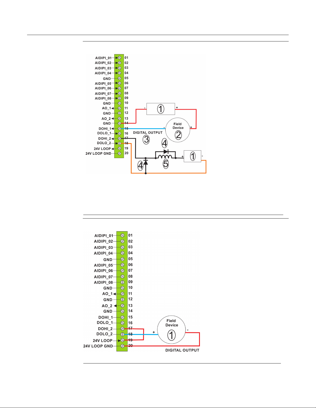
DO Wiring: Low Side Internal Switch
1
Power Supply 30VDC Max
2
50 mA load max field device
3
Low side switch - internal
4
Suppression diodes
5
Relay coil or inductive load
1
500 mA load max field device
FB3000 Personality Module Field Installation Guide
D301872X012
June 2021
Digital Output (DO) Wiring – Dry Contact Closure using 24V Loop Supply
13
Page 16

FB3000 Personality Module Field Installation Guide
1
500 mA load max field device
2
30VDC Max Power Supply
3
DOHI_1/DOLO_1 configured as an external low side switch (LSS)
4
DOHI_2/DOLO_2 configured as an external high side switch (HSS)
D301872X012
June 2021
Digital Output (DO) Wiring –Dry Contact Closure [img=DO_Wiring_Example2.jpg,cdr]
14
Page 17

Pulse Input (PI)
1
External Device (Because no power supply, requires internal pull-up to be enabled.)
2
External Device
3
30VDC Max Power Supply
4
Control signal
Pulse Input (PI) Wiring
FB3000 Personality Module Field Installation Guide
D301872X012
June 2021
15
Page 18

FB3000 RTU Personality Module Field Installation Guide
For customer service and technical support,
Global Headquarters,
North America, and Latin America:
end-user.
Europe:
Middle East/Africa:
Asia-Pacific:
T +65 6777 8211| F +65 6777 0947
D301872X012
June 2021
visit www.Emerson.com/SupportNet
Emerson Automation Solutions
Remote Automation Solutions
6005 Rogerdale Road
Houston, TX 77072 U.S.A.
T +1 281 879 2699 | F +1 281 988 4445
www.Emerson.com/RemoteAutomation
Emerson Automation Solutions
Remote Automation Solutions
Unit 1, Waterfront Business Park
Dudley Road, Brierley Hill
Dudley DY5 1LX UK
T +44 1384 487200
Emerson Automation Solutions
Remote Automation Solutions
Emerson FZE
P.O. Box 17033
Jebel Ali Free Zone – South 2
Dubai U.A.E.
T +971 4 8118100 | F +971 4 8865465
Emerson Automation Solutions
Remote Automation Solutions
1 Pandan Crescent
Singapore 128461
© 2018-2021 Remote Automation Solutions, a business unit of Emerson Automation
Solutions. All rights reserved.
This publication is for informational purposes only. While every effort has been made to ensure
accuracy, this publication shall not be read to include any warranty or guarantee, express or
implied, including as regards the products or services described or their use or applicability.
Remote Automation Solutions (RAS) reserves the right to modify or improve the designs or
specifications of its products at any time without notice. All sales are governed by RAS terms
and conditions which are available upon request. RAS accepts no responsibility for proper
selection, use or maintenance of any product, which remains solely with the purchaser and/or
Remote Automation Solutions
 Loading...