

Remote Automation Solutions FB2100/FB2200 Flow Computer Door/Accessories Field Replacement Guide Manuals & Guides
Page 1

FB2100/FB2200 Flow Computer Door/Accessories Field Replacement Guide
FB2100/FB2200 Flow Computer
Door/Accessories
Field Replacement Guide
D301825X012
November 2020
For Part Numbers (Kits):
399291-01-0: Door Cover Assembly
399266-01-0: Radio Bracket
621661010-KIT: Door Intrusion Switch
399394-00-0: Aluminum Door Clamps
399267-01-0: Display Overlay Assembly
Remote Automation Solutions
Page 2

FB2100/FB2200 Flow Computer Door/Accessories Field Replacement Guide
D301825X012
November 2020
Device Safety Considerations
Reading these Instructions
Before operating the device, read these instructions carefully and understand their safety implications. In some situations,
improperly using this device may result in damage or injury. Keep this manual in a convenient location for future reference.
Note that these instructions may not cover all details or variations in equipment or cover every possible situation regarding
installation, operation, or maintenance. Should problems arise that are not covered sufficiently in the text, immediately
contact Customer Support for further information.
Protecting Operating Processes
A failure of this device – for whatever reason -- may leave an operating process without appropriate protection and could result
in possible damage to property or injury to persons. To protect against this, you should review the need for additional backup
equipment or provide alternate means of protection (such as alarm devices, output limiting, fail-safe valves, relief valves,
emergency shutoffs, emergency switches, etc.). Contact Remote Automation Solutions for additional information.
Returning Equipment
If you need to return any equipment to Remote Automation Solutions, it is your responsibility to ensure that the equipment
has been cleaned to safe levels, as defined and/or determined by applicable federal, state and/or local law regulations or
codes. You also agree to indemnify Remote Automation Solutions and hold Remote Automation Solutions harmless from any
liability or damage which Remote Automation Solutions may incur or suffer due to your failure to ensure device cleanliness.
Grounding Equipment
Ground metal enclosures and exposed metal parts of electrical instruments in accordance with OSHA rules and regulations as
specified in Design Safety Standards for Electrical Systems, 29 CFR, Part 1910, Subpart S, dated: April 16, 1981 (OSHA rulings are
in agreement with the National Electrical Code). You must also ground mechanical or pneumatic instruments that include
electrically operated devices such as lights, switches, relays, alarms, or chart drives.
Important: Complying with the codes and regulations of authorities having jurisdiction is essential to ensuring personnel
safety. The guidelines and recommendations in this manual are intended to meet or exceed applicable codes and regulations.
If differences occur between this manual and the codes and regulations of authorities having jurisdiction, those codes and
regulations must take precedence.
Protecting from Electrostatic Discharge (ESD)
This device contains sensitive electronic components which be damaged by exposure to an ESD voltage. Depending on the
magnitude and duration of the ESD, it can result in erratic operation or complete failure of the equipment. Ensure that you
correctly care for and handle ESD-sensitive components.
System Training
A well-trained workforce is critical to the success of your operation. Knowing how to correctly install, configure, program,
calibrate, and trouble-shoot your Emerson equipment provides your engineers and technicians with the skills and confidence
to optimize your investment. Remote Automation Solutions offers a variety of ways for your personnel to acquire essential
system expertise. Our full-time professional instructors can conduct classroom training at several of our corporate offices, at
your site, or even at your regional Emerson office. You can also receive the same quality training via our live, interactive
Emerson Virtual Classroom and save on travel costs. For our complete schedule and further information, contact the Remote
Automation Solutions Training Department at 800-338-8158 or email us at education@emerson.com.
Ethernet Connectivity
This automation device is intended to be used in an Ethernet network which does not have public access. The inclusion of this
device in a publicly accessible Ethernet-based network is
not recommended.
Page 3

FB2100/FB2200 Flow Computer Doors/Accessories Field Replacement Guide
Item
Field Replacement Kit
Part Number
UL File Number for these kits: E192567
WARNING
Removing/Replacing Doors/Accessories
This guide covers the five replacement kits for doors or brackets for the FB2100 and FB2200 Flow
Computers.
Restriction
Hazardous area approvals request that any part replaced in the field be the exact same part (“likefor-like”). Upgrading or substituting different parts violates hazardous area certification.
Important
Only use accessories supplied with the flow computer or sold by Emerson as spare parts for this
flow computer. If you substitute a part you obtain elsewhere
it is the identical part from the same manufacturer as that supplied with the flow computer from
Emerson.
Refer to the table below for the correct field replacement part number.
you will void your certification unless
D301825X012
November 2020
Display Cover Assembly (plastic) 399291-01-0
Display Overlay Window 399267-01-0
Radio Bracket 399266-01-0
Door Intrusion Switch 621661010-KIT
Aluminum Door Clamps (brackets) (pack of 2) 399394-00-0
Required Tools
#2 Phillips-head screwdriver
#3 Phillips-head screwdriver
1/8-inch flat head screwdriver
3/8-inch (10 mm) hex nut driver.
Hexagonal torque wrenches. Ranges must include 4 to 6 in-lbs (0.5 to 0.7 N-m) and 18 to 20
in-lbs (2 to 2.3 N-m).
Permanent marker pen
Ambient Temperature Range
May be used up to a maximum ambient temperature of 80C and a minimum ambient temperature
of -40C; see product data plate for ambient temperature.
Electrical Rating
Input Voltage: 10.5 Vdc to 30 Vdc external supply (Max power at 10 watts)
EXPLOSION HAZARD –Do not disconnect equipment unless power has been removed or the
area is known to be non-hazardous.
1
Page 4

FB2100/FB2200 Flow Computer Doors/Accessories Field Replacement Guide
WARNING
DANGER
D301825X012
November 2020
EXPLOSION HAZARD -Substitution of any components may impair suitability for Class I, Division
2.
EXPLOSION HAZARD: Never open the enclosure in a hazardous location. Opening the enclosure
in a hazardous location could result in an explosion.
Removing/Replacing the Display Cover Assembly
The display cover assembly provides a cover to the window you use to view the HMI module
display.
UL Field Installed Accessory Kit for Use in Class I, Division 2, Groups A, B, C, and D
Flow Computer Display Cover Field Installed Accessory Kit Part No. 399291-01-0
1. Open the flow computer enclosure.
2. On the back of the enclosure door are four screws with washers that hold the display cover
assembly to the door. Use a #2 Phillips-head screwdriver to remove the screws and washers
(save them in a safe place).
2
Page 5

FB2100/FB2200 Flow Computer Doors/Accessories Field Replacement Guide
D301825X012
November 2020
3. When the screws and washers are removed, pull the old display/cover assembly off and set it
aside.
4. Peel off any residual gasket material which might be stuck to the outside of the enclosure
door.
5. Align the new display/cover assembly with the outside of the enclosure door, and use the
screws and washers to attach it from the other side of the door. Torque screws to 4 to 6 inlbs (0.5 to 0.7 N m).
6. Close the flow computer enclosure.
3
Page 6
FB2100/FB2200 Flow Computer Doors/Accessories Field Replacement Guide
D301825X012
November 2020
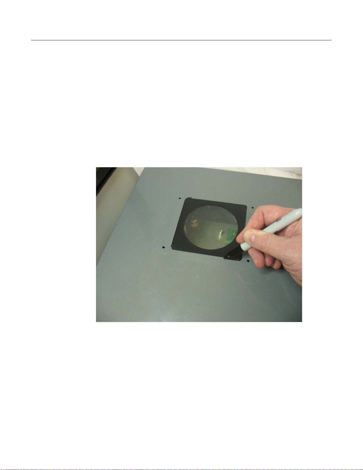
Removing/Replacing the Display Overlay Window
The display overlay window is a thin membrane through which you can view the HMI module or
activate HMI module buttons with your finger. The display cover assembly protects the window
from moisture, dust, or weather.
UL Field Installed Accessory Kit for Use in Class I, Division 2, Groups A, B, C, and D
Flow Computer Display Overlay Window Field Installed Accessory Kit Part No. 399267-01-0
1. Remove the display cover assembly as described in steps 1 through 4 of Removing/Replacing
the Display Cover Assembly.
2. Using a permanent marker pen, trace the outline of the existing display overlay window. This
is important so you line the new one up correctly to ensure a weather-tight seal when the
door cover is closed.
4
Page 7
FB2100/FB2200 Flow Computer Doors/Accessories Field Replacement Guide
D301825X012
November 2020
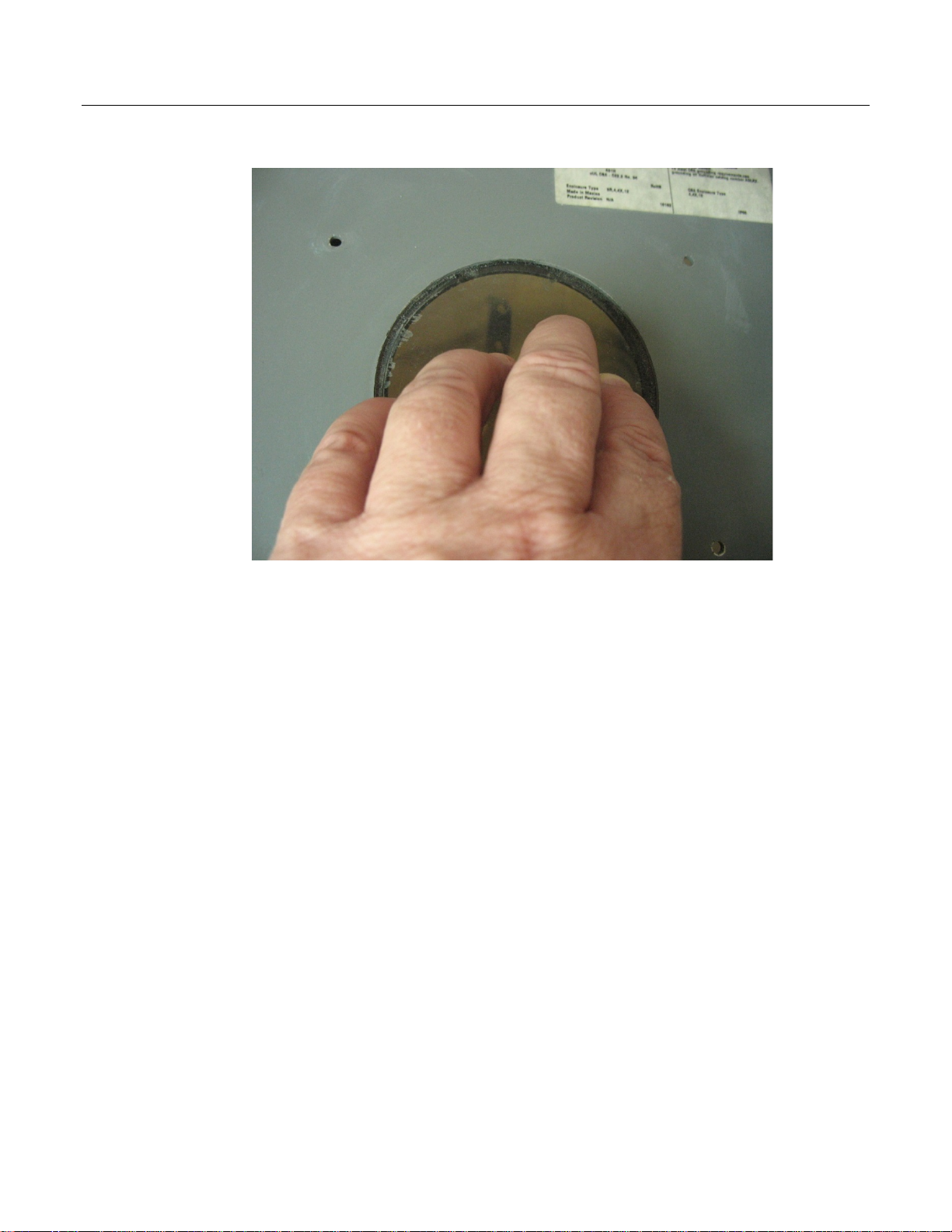
3. From the inside side of the enclosure door, press hard on the display overlay so it pops off.
Peel off any residual material still stuck to outside of the door.
4. Align the new display overlay window with the outline you traced in step 2.
5. Press the new display overlay window onto the enclosure, and press down on all the edges to
ensure that it seals tightly.
6. Replace the display cover assembly as described in steps 5 and 6 of Removing/Replacing the
Display Cover Assembly.
5
Page 8

FB2100/FB2200 Flow Computer Doors/Accessories Field Replacement Guide
D301825X012
November 2020
Removing/Replacing the Door Intrusion Switch
UL Field Installed Accessory Kit for Use in Class I, Division 2, Groups A, B, C, and D
Flow Computer Door Intrusion Switch Field Installed Accessory Kit Part No. 621661010-KIT
1. Open the flow computer enclosure.
2. Use a 3/8” (10 mm) hex nut driver to loosen the hex nuts which hold the door intrusion
switch assembly to the flow computer enclosure and pull out the door intrusion switch
assembly. Save the hex nuts.
3. Trace the I/O wires from the door switch to the terminal block where they connect to the I/O
termination board, and disconnect the wires from the terminal block using a 1/8” flat head
6
Page 9

FB2100/FB2200 Flow Computer Doors/Accessories Field Replacement Guide
D301825X012
November 2020
screwdriver. (Depending upon how it was wired at the factory, it may go to the DOOR
CONTACT terminal or to a digital input.) Set the old assembly aside.
4. Take the new (replacement) door intrusion switch assembly and attach its wires to the
terminal block in the last step.
5. Attach the door intrusion switch assembly to the flow computer enclosure using the hex
nuts. Torque nuts to 4 to 6 in lbs (0.5 to 0.7 N m).
6. Close the flow computer enclosure.
Removing/Replacing the Aluminum Door Clamps
The aluminum flow computer enclosure includes six clamps along the edge of the door (two at the
top, two on the bottom, two at the side).
UL Field Installed Accessory Kit for Use in Class I, Division 2, Groups A, B, C, and D
Flow Computer Aluminum Door Clamp Field Installed Accessory Kit Part No. 399394-00-0
1. To remove/replace a clamp, use a #3 Phillips-head screwdriver to remove the screw which
holds the clamp in place and set the old clamp aside. Save the screw.
7
Page 10

FB2100/FB2200 Flow Computer Doors/Accessories Field Replacement Guide
D301825X012
November 2020
2. Place the new clamp in place so it holds the lip of the door. Tighten the screw to hold the
clamp in place. Torque screw to 18 to 20 in lbs (2 to 2.3 N m).
Removing/Replacing the Radio Bracket
UL Field Installed Accessory Kit for Use in Class I, Division 2, Groups A, B, C, and D
Flow Computer Radio Bracket Field Installed Accessory Kit Part No. 399266-01-0
8
Page 11
FB2100/FB2200 Flow Computer Doors/Accessories Field Replacement Guide
1. Open the flow computer enclosure.
2. Disconnect all cables from the installed radio (if you have one installed).
D301825X012
November 2020
9
Page 12

FB2100/FB2200 Flow Computer Doors/Accessories Field Replacement Guide
D301825X012
November 2020
3. Use a #2 Phillips-head screwdriver to loosen the two captive fastening screws on the radio
bracket above and below the radio.
4. Pull the radio with the radio bracket attached out of the flow computer enclosure.
10
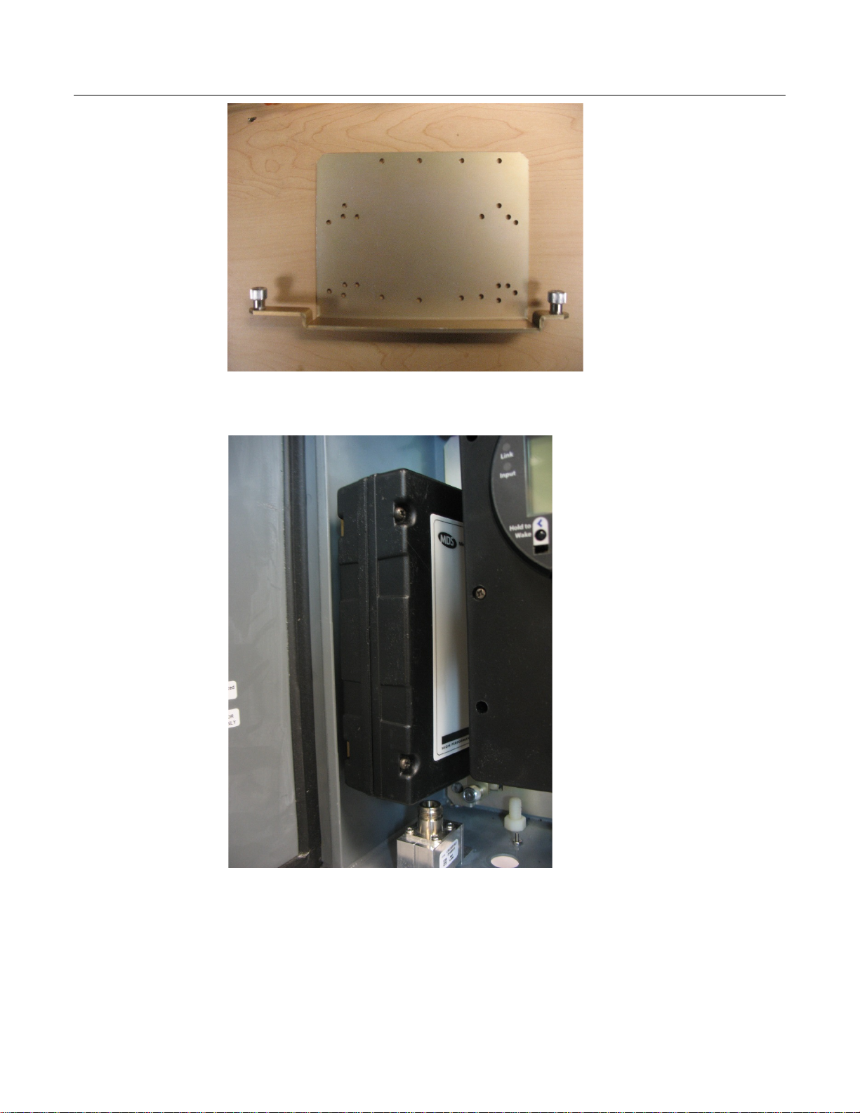
5. Turn the radio/radio bracket assembly over and use a #2 Phillips-head screwdriver to remove
the screws that hold the radio to the radio bracket. Set the old radio bracket aside.
Page 13

FB2100/FB2200 Flow Computer Doors/Accessories Field Replacement Guide
D301825X012
November 2020
6. Attach the radio to the new (replacement) radio bracket using the screws you removed in
the last step. Torque screws to 4 to 6 in lbs (0.5 to 0.7 N m).
7. Use the captive fastening screws on the bracket to attach the radio/radio bracket assembly
inside the flow computer enclosure. Torque screws to 4 to 6 in lbs (0.5 to 0.7 N m).
8. Connect the radio cables to the radio.
9. Close the flow computer enclosure.
11
Page 14

FB1100/FB1200 Flow Computer Doors/Accessories Field Replacement Guide
For customer service and technical support,
Global Headquarters,
North America, and Latin America:
end-user.
Europe:
Middle East/Africa:
Asia-Pacific:
T +65 6777 8211| F +65 6777 0947
D301825X012
November 2020
visit www.Emerson.com/SupportNet
Emerson Automation Solutions
Remote Automation Solutions
6005 Rogerdale Road
Houston, TX 77072 U.S.A.
T +1 281 879 2699 | F +1 281 988 4445
www.Emerson.com/RemoteAutomation
Emerson Automation Solutions
Remote Automation Solutions
Unit 1, Waterfront Business Park
Dudley Road, Brierley Hill
Dudley DY5 1LX UK
T +44 1384 487200 | F +44 1384 487258
Emerson Automation Solutions
Remote Automation Solutions
Emerson FZE
P.O. Box 17033
Jebel Ali Free Zone – South 2
Dubai U.A.E.
T +971 4 8118100 | F +971 4 8865465
Emerson Automation Solutions
Remote Automation Solutions
1 Pandan Crescent
Singapore 128461
© 2018-2020 Remote Automation Solutions, a business unit of Emerson Automation
Solutions. All rights reserved.
This publication is for informational purposes only. While every effort has been made to ensure
accuracy, this publication shall not be read to include any warranty or guarantee, express or
implied, including as regards the products or services described or their use or applicability.
Remote Automation Solutions (RAS) reserves the right to modify or improve the designs or
specifications of its products at any time without notice. All sales are governed by RAS terms
and conditions which are available upon request. RAS accepts no responsibility for proper
selection, use or maintenance of any product, which remains solely with the purchaser and/or
Remote Automation Solutions
 Loading...