

Remote Automation Solutions FB2100/FB2200 Flow Computer Battery Field Replacement Guide Manuals & Guides
Page 1

FB2100/FB2200 Flow Computer Battery Field Replacement Guide
FB2100/FB2200 Flow Computer
Battery
Field Replacement Guide
D301823X012
November 2020
For Part Numbers (Kits):
399285-01-0: Battery
Remote Automation Solutions
Page 2

FB2100/FB2200 Flow Computer Battery Field Replacement Guide
D301823X012
November 2020
Device Safety Considerations
Reading these Instructions
Before operating the device, read these instructions carefully and understand their safety implications. In some situations,
improperly using this device may result in damage or injury. Keep this manual in a convenient location for future reference.
Note that these instructions may not cover all details or variations in equipment or cover every possible situation regarding
installation, operation, or maintenance. Should problems arise that are not covered sufficiently in the text, immediately
contact Customer Support for further information.
Protecting Operating Processes
A failure of this device – for whatever reason -- may leave an operating process without appropriate protection and could result
in possible damage to property or injury to persons. To protect against this, you should review the need for additional backup
equipment or provide alternate means of protection (such as alarm devices, output limiting, fail-safe valves, relief valves,
emergency shutoffs, emergency switches, etc.). Contact Remote Automation Solutions for additional information.
Returning Equipment
If you need to return any equipment to Remote Automation Solutions, it is your responsibility to ensure that the equipment
has been cleaned to safe levels, as defined and/or determined by applicable federal, state and/or local law regulations or
codes. You also agree to indemnify Remote Automation Solutions and hold Remote Automation Solutions harmless from any
liability or damage which Remote Automation Solutions may incur or suffer due to your failure to ensure device cleanliness.
Grounding Equipment
Ground metal enclosures and exposed metal parts of electrical instruments in accordance with OSHA rules and regulations as
specified in Design Safety Standards for Electrical Systems, 29 CFR, Part 1910, Subpart S, dated: April 16, 1981 (OSHA rulings are
in agreement with the National Electrical Code). You must also ground mechanical or pneumatic instruments that include
electrically operated devices such as lights, switches, relays, alarms, or chart drives.
Important: Complying with the codes and regulations of authorities having jurisdiction is essential to ensuring personnel
safety. The guidelines and recommendations in this manual are intended to meet or exceed applicable codes and regulations.
If differences occur between this manual and the codes and regulations of authorities having jurisdiction, those codes and
regulations must take precedence.
Protecting from Electrostatic Discharge (ESD)
This device contains sensitive electronic components which be damaged by exposure to an ESD voltage. Depending on the
magnitude and duration of the ESD, it can result in erratic operation or complete failure of the equipment. Ensure that you
correctly care for and handle ESD-sensitive components.
System Training
A well-trained workforce is critical to the success of your operation. Knowing how to correctly install, configure, program,
calibrate, and trouble-shoot your Emerson equipment provides your engineers and technicians with the skills and confidence
to optimize your investment. Remote Automation Solutions offers a variety of ways for your personnel to acquire essential
system expertise. Our full-time professional instructors can conduct classroom training at several of our corporate offices, at
your site, or even at your regional Emerson office. You can also receive the same quality training via our live, interactive
Emerson Virtual Classroom and save on travel costs. For our complete schedule and further information, contact the Remote
Automation Solutions Training Department at 800-338-8158 or email us at education@emerson.com.
Ethernet Connectivity
This automation device is intended to be used in an Ethernet network which does not have public access. The inclusion of this
device in a publicly accessible Ethernet-based network is not recommended.
Page 3

FB2100/FB2200 Flow Computer Battery Field Replacement Guide
Item
Field Replacement Kit
Part Number
UL Kit File Number: E192567
DANGER
Removing/Replacing Batteries
The flow computer includes two different types of main battery enclosures. One uses a strap to
hold the battery in place, the other uses a hook-and-loop pad to secure the battery. This guide
includes separate procedures depending upon the battery enclosure used.
Restriction
Hazardous area approvals require that any part replaced in the field be the exact same part (like for
like). Upgrading or substituting different parts violates hazardous area certification.
Refer to the table below for the correct field replacement kit part number
10.5 Ah Lead Acid Battery for use with solar panel 399285-01-0
D301823X012
November 2020
Important
Use only accessories (batteries) supplied with the flow computer or sold by Emerson as spare parts
for this flow computer. Substituting a part you obtain elsewhere (such as a battery)
approval certification.
Ambient Temperature Range
May be used up to a maximum ambient temperature of 80°C and a minimum ambient
temperature of –40°C; refer to the data plate attached to the device for ambient temperature.
Required Tools
#2 Phillips-head screwdriver
Hexagonal torque wrenches. Ranges must include 2 to 4 in-lbs (0.2 to 0.5 N-m).
Electrical Ratings
Input Voltage: 10.5 Vdc to 30 Vdc external supply (Max power at 10 watts)
Important
If this equipment is used in a manner not specified by the manufacturer, the protection provided by
equipment may be impaired.
voids your
DANGER
EXPLOSION HAZARD: Ensure the area in which you perform this operation is non-hazardous.
Performing this operation in a hazardous area could result in an explosion.
EXPLOSION HAZARD: Never remove end cap(s) in a hazardous location. Removing end cap(s) in a
hazardous location could result in an explosion.
1
Page 4

FB2100/FB2200 Flow Computer Battery Field Replacement Guide
WARNING
WARNING
WARNING
only
WARNING
D301823X012
November 2020
EXPLOSION HAZARD -Substitution of any components may impair suitability for Class I, Division
2.
EXPLOSION HAZARD - Do not disconnect equipment unless power has been removed or the area
is known to be non-hazardous.
EXPLOSION HAZARD – Do not replace batteries unless power has been switched off or the area is
known to be non-hazardous.
Note
Use these cell batteries only in devices where the servicing of the cell circuit and replacement of the
lithium cells is done by a trained technician.
Change batteries
in an area known to be non-hazardous.
Removing/Replacing the Main Power Battery (Strap Holds Battery)
UL Listed Lead Acid Battery Field Installed Accessory Kit for Use in Class I, Division 2, Groups A, B, C,
and D.
Flow Computer Lead Acid Battery Field Installed Accessory Kit Part No. 399285-01-0 for Use
with UL Listed Class I, Division 2, Groups A, B, C, & D Model Series FB2100 and FB2200
There are no user-serviceable parts inside the battery pack. Do not open the battery pack as you
may damage the battery pack or injure yourself.
Keep the replacement battery pack handy during the procedure.
1. Remove the plastic tabs covering the connectors on the new battery pack.
2
Page 5

FB2100/FB2200 Flow Computer Battery Field Replacement Guide
Removing Plastic Tabs from New Battery Pack
D301823X012
November 2020
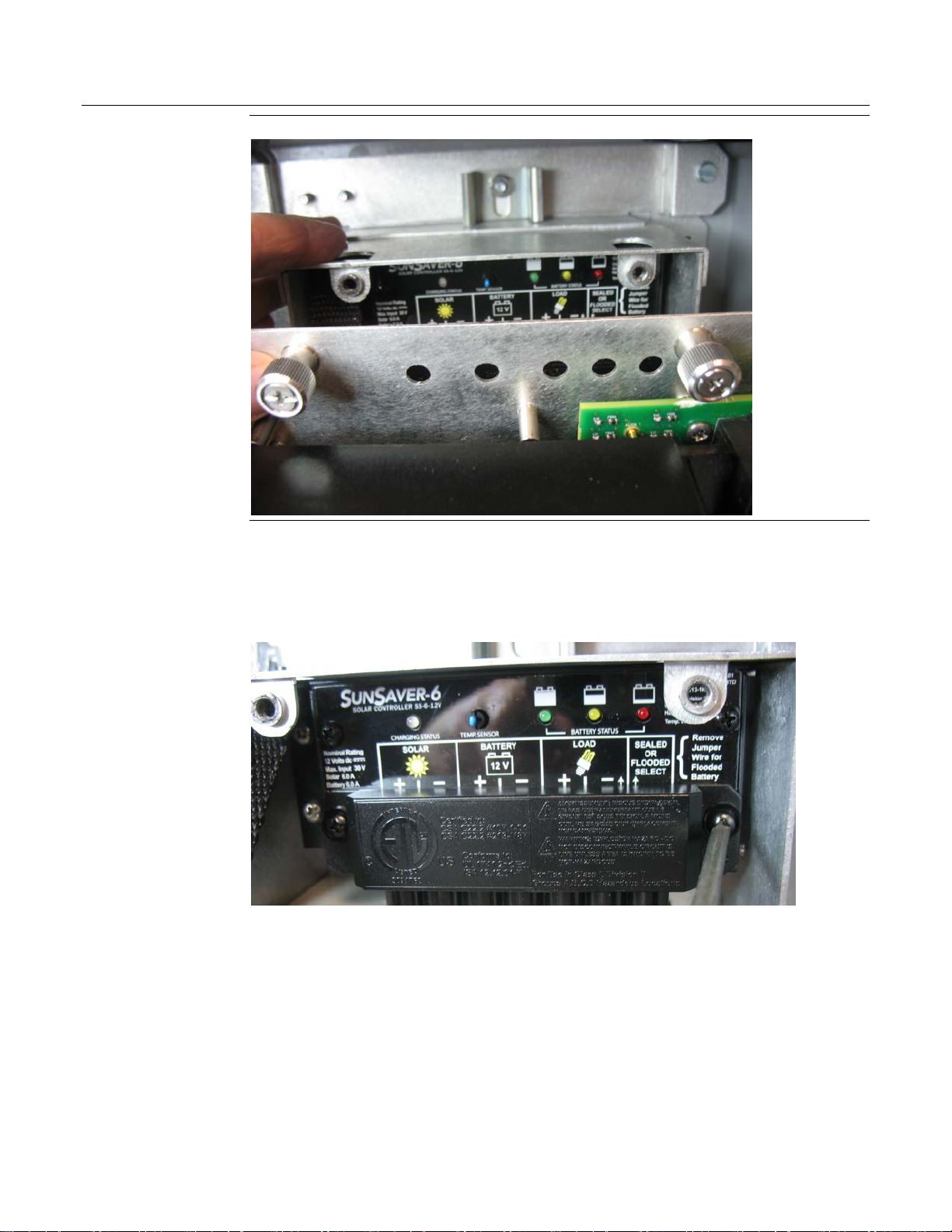
2. Open the enclosure.
3. Loosen the two captive fastening screws at the top of the of the battery compartment and
carefully rotate the electronics assembly towards you to reveal the inside of the battery
compartment. A strap prevents the front of the compartment from rotating too far forward.
3
Page 6
FB2100/FB2200 Flow Computer Battery Field Replacement Guide
D301823X012
November 2020
Loosen Captive Fastening Screws and Rotate Assembly Forward
4. If you have an internal solar regulator installed in the battery compartment, you must
remove the termination cover. Remove the two screws (left and right) that fasten the
termination cover to the solar regulator, and then set the termination cover aside. (If you
don’t have an internal solar regulator, skip to Step 5.)
®
5. A strap with a VELCRO
brand fastener holds the battery in place. Unstrap the battery but
leave the connectors on the current battery connected. Gently lift the battery with the
battery cable attached out of the compartment. You may want to place it on top of the flow
computer enclosure.
4
Page 7
FB2100/FB2200 Flow Computer Battery Field Replacement Guide
Unstrap the Old Battery Pack (Leave Connected to Cable)
D301823X012
November 2020
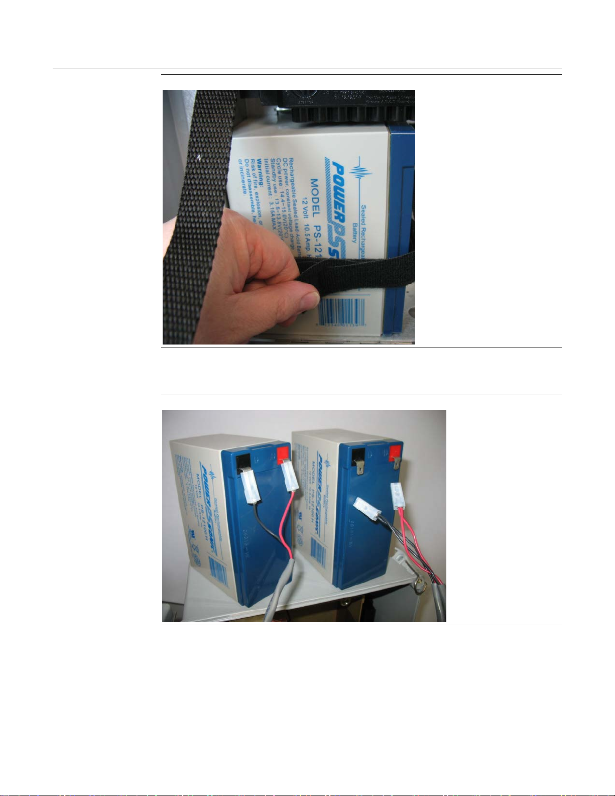
6. Place the old battery on top of the flow computer enclosure and place the new battery next
to it.
Old Battery (left) and New Battery (right) Sit on Enclosure
7. The battery cable is divided into two branches, each with its own pair of connectors. Take the
free pair of connectors and connect them to the
connector attaches to the red connection point on the new battery and the black (negative)
wire connector attaches to the black connection point on the new battery.
new battery; the red (positive) wire
5
Page 8

FB2100/FB2200 Flow Computer Battery Field Replacement Guide
D301823X012
November 2020
Connect New Battery (Both Batteries Now Connected)
8. Now disconnect the old battery from its connectors and set the old battery aside (be sure to
dispose of it safely in accordance with local regulations).
Old Battery Disconnected (left) New Battery Remains Connected (right)
9. The battery strap must already be threaded through the holes of the battery compartment.
6
Page 9

FB2100/FB2200 Flow Computer Battery Field Replacement Guide
D301823X012
November 2020
10. Pick up the new battery and carefully ease it into the battery compartment with the writing
on the battery facing out and the connectors on the upper right-hand side. Nothing
(including the strap) can be
behind the battery.
11. Carefully push the battery under the solar regulator (if present) and against the back of the
compartment, now strap it in tightly by pulling the ends of the strap.
7
Page 10

FB2100/FB2200 Flow Computer Battery Field Replacement Guide
D301823X012
November 2020
12. The strap includes a narrow opening into which you can slide the other end of the strap to
help you tighten it.
13. Route the extra portion of the strap as well as the wires of the free portion of the battery
cable so that they sit in an open area of the battery compartment.
14. If you had to remove the termination cover of an internal solar regulator (Step 4), re-attach
the termination cover.
15. Rotate the electronics assembly up against the battery compartment and tighten the captive
fastening screws with a torque value of 2 to 4 in-lbs (0.2 to 0.5 N-m) to close the
compartment.
16. Close the flow computer enclosure.
8
Page 11
FB2100/FB2200 Flow Computer Battery Field Replacement Guide
WARNING
Removing/Replacing the Main Power Battery (Pad Holds Battery)
UL Listed Lead Acid Battery Field Installed Accessory Kit for Use in Class I, Division 2, Groups A, B, C,
and D
Flow Computer Lead Acid Battery Field Installed Accessory Kit Part No. 399285-01-0 for Use
with UL Listed Class I, Division 2, Groups A, B, C, and D Model Series FB2100 and FB2200
D301823X012
November 2020
There are no user-serviceable parts inside the battery pack. Do not open the battery pack as you
may damage the battery pack or injure yourself.
Keep the replacement battery pack handy during the procedure.
1. Remove the plastic tabs covering the connectors on the new battery pack.
Removing Plastic Tabs from New Battery Pack
2. Open the enclosure.
9
Page 12

FB2100/FB2200 Flow Computer Battery Field Replacement Guide
D301823X012
November 2020
3. Loosen the two captive fastening screws at the top of the of the battery compartment and
carefully rotate the electronics assembly towards you to reveal the inside of the battery
compartment. A strap prevents the front of the compartment from rotating too far forward.
Loosen Captive Fastening Screws and Rotate Assembly Forward
10
Page 13

FB2100/FB2200 Flow Computer Battery Field Replacement Guide
D301823X012
November 2020
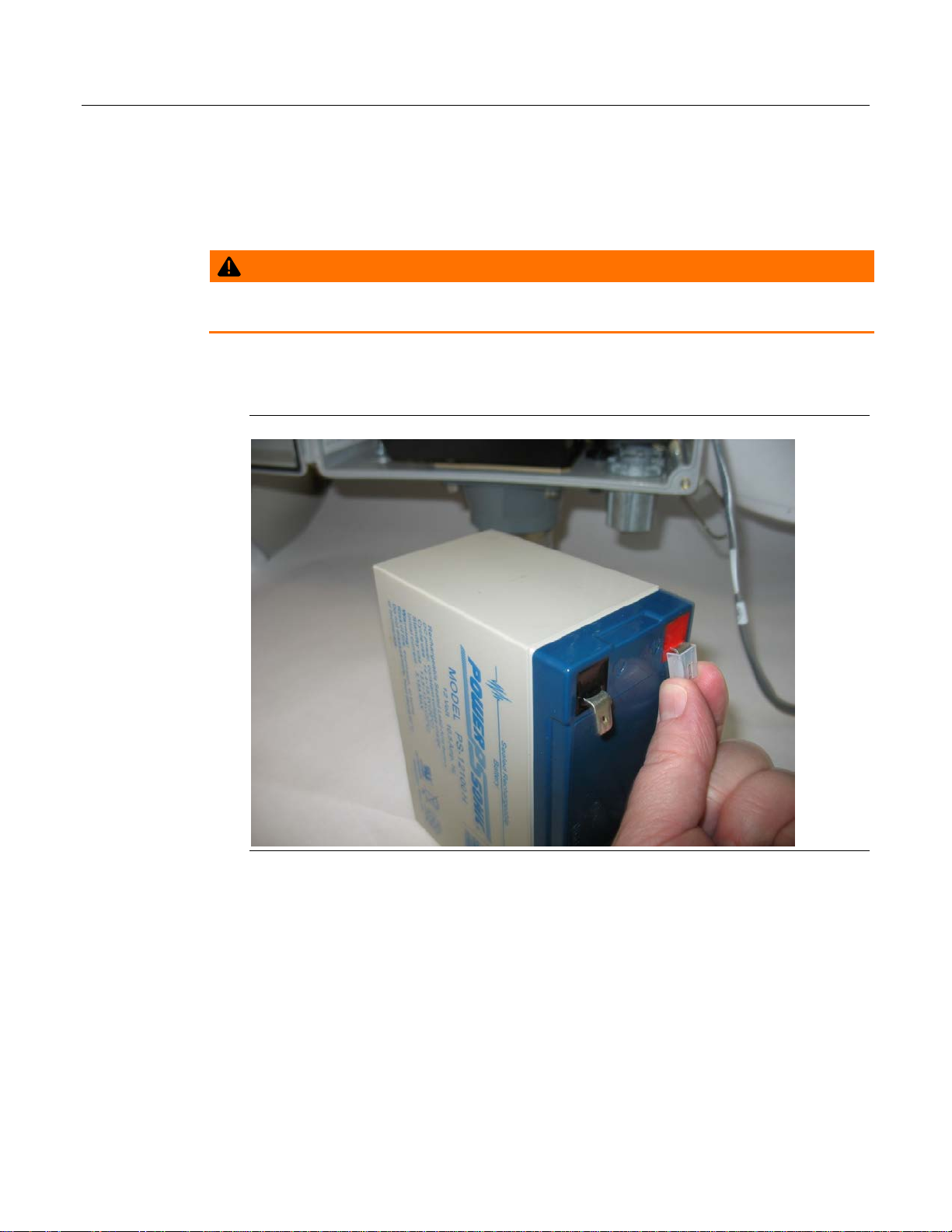
4. A VELCRO brand fastener on the back of the battery secures it to the back of the battery
compartment. Leave the connectors on the current battery connected. Place your fingers
behind the battery pack and pry it off of the fastener on the back of the compartment; you
may need to use both hands. Gently lift the battery with the battery cable attached out of
the compartment. You may want to place it on top of the flow computer enclosure.
Pry Out Old Battery Pack (Leaving Connected to Cable)
11
Page 14

FB2100/FB2200 Flow Computer Battery Field Replacement Guide
D301823X012
November 2020
5. Place the old battery on top of the flow computer enclosure and place the new battery next
to it.
Old Battery (left) and New Battery (right) Sit on Enclosure
6. The battery cable is divided into two branches, each with its own pair of connectors. Take the
free pair of connectors and connect them to the
connector attaches to the red connection point on the new battery and the black (negative)
wire connector attaches to the black connection point on the new battery.
Connect New Battery (Both Batteries Now Connected)
new battery; the red (positive) wire
12
Page 15
FB2100/FB2200 Flow Computer Battery Field Replacement Guide
D301823X012
November 2020
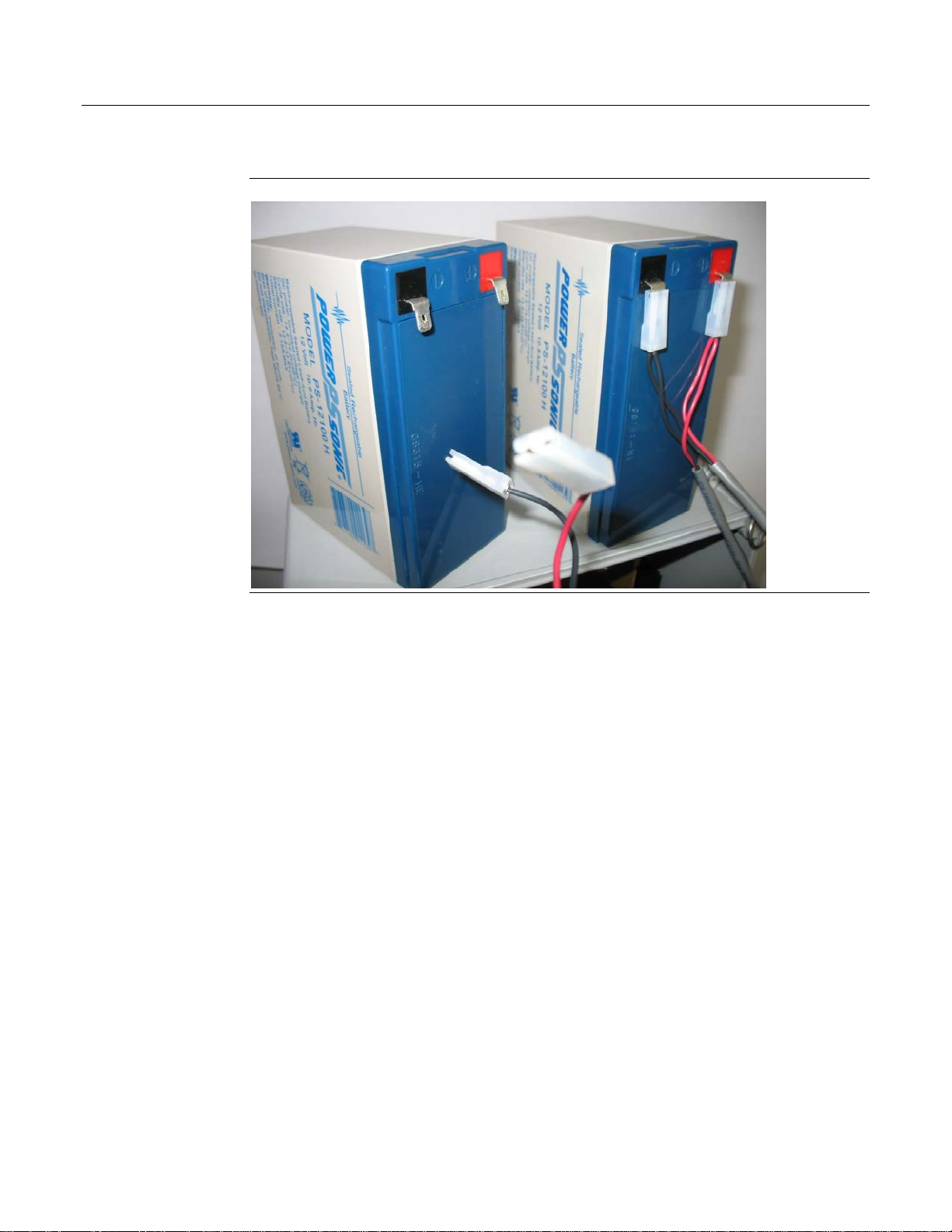
7. Now disconnect the old battery from its connectors and set the old battery aside (be sure to
dispose of it safely in accordance with local regulations).
Old Battery (left) Disconnected; New Battery (right) Remains Connected
8. Pick up the new battery and align it with the lower left edge of the battery compartment
with the writing on the battery facing out and the connectors on the upper right-hand side.
Press it against the back of the compartment so the fastener pad on the back of the battery
secures to the back of the battery compartment. Route the wires of the free portion of the
battery cable so that they sit in the open area at the top of the battery compartment.
9. Rotate the electronics assembly up against the battery compartment and tighten the captive
fastening screws with a torque value of 2 to 4 in-lbs. (0.2 to 0.5 N-m) to close the
compartment.
10. Close the flow computer enclosure.
13
Page 16

FB2100/FB2200 Flow Computer Battery Field Replacement Guide
For customer service and technical support,
Global Headquarters,
North America, and Latin America:
end-user.
Europe:
Middle East/Africa:
Asia-Pacific:
T +65 6777 8211| F +65 6777 0947
D301823X012
November 2020
visit www.Emerson.com/SupportNet
Emerson Automation Solutions
Remote Automation Solutions
6005 Rogerdale Road
Houston, TX 77072 U.S.A.
T +1 281 879 2699 | F +1 281 988 4445
www.Emerson.com/RemoteAutomation
Emerson Automation Solutions
Remote Automation Solutions
Unit 1, Waterfront Business Park
Dudley Road, Brierley Hill
Dudley DY5 1LX UK
T +44 1384 487200 | F +44 1384 487258
Emerson Automation Solutions
Remote Automation Solutions
Emerson FZE
P.O. Box 17033
Jebel Ali Free Zone – South 2
Dubai U.A.E.
T +971 4 8118100 | F +971 4 8865465
Emerson Automation Solutions
Remote Automation Solutions
1 Pandan Crescent
Singapore 128461
© 2018-2020 Remote Automation Solutions, a business unit of Emerson Automation
Solutions. All rights reserved.
This publication is for informational purposes only. While every effort has been made to ensure
accuracy, this publication shall not be read to include any warranty or guarantee, express or
implied, including as regards the products or services described or their use or applicability.
Remote Automation Solutions (RAS) reserves the right to modify or improve the designs or
specifications of its products at any time without notice. All sales are governed by RAS terms
and conditions which are available upon request. RAS accepts no responsibility for proper
selection, use or maintenance of any product, which remains solely with the purchaser and/or
Remote Automation Solutions
 Loading...