

Remote Automation Solutions FB2100/FB2200 Flow Computer 30W Solar Panel Field Replacement Guide Manuals & Guides
Page 1
FB2100/FB2200 Flow Computer 30W Solar Panel Field Replacement Guide
FB2100/FB2200 Flow Computer
30W Solar Panel
Field Replacement Guide
D301824X012
November 2020
For Part Numbers (Kits):
395555-02-7: Solar Panel
399288-01-0: Battery Cable
396701-03-0: Solar Controller Cable
395829-01-0: Fuses
396992-01-3: Solar Controller
Remote Automation Solutions
Page 2

FB2100/FB2200 Flow Computer 30W Solar Panel Field Replacement Guide
D301824X012
November 2020
Page 3

FB1100/FB1200 Flow Computer Battery Field Replacement Guide
D301815X012
November 2019
Device Safety Considerations
Reading these Instructions
Before operating the device, read these instructions carefully and understand their safety implications. In some situations,
improperly using this device may result in damage or injury. Keep this manual in a convenient location for future reference.
Note that these instructions may not cover all details or variations in equipment or cover every possible situation regarding
installation, operation, or maintenance. Should problems arise that are not covered sufficiently in the text, immediately
contact Customer Support for further information.
Protecting Operating Processes
A failure of this device – for whatever reason -- may leave an operating process without appropriate protection and could result
in possible damage to property or injury to persons. To protect against this, you should review the need for additional backup
equipment or provide alternate means of protection (such as alarm devices, output limiting, fail-safe valves, relief valves,
emergency shutoffs, emergency switches, etc.). Contact Remote Automation Solutions for additional information.
Returning Equipment
If you need to return any equipment to Remote Automation Solutions, it is your responsibility to ensure that the equipment
has been cleaned to safe levels, as defined and/or determined by applicable federal, state and/or local law regulations or
codes. You also agree to indemnify Remote Automation Solutions and hold Remote Automation Solutions harmless from any
liability or damage which Remote Automation Solutions may incur or suffer due to your failure to ensure device cleanliness.
Grounding Equipment
Ground metal enclosures and exposed metal parts of electrical instruments in accordance with OSHA rules and regulations as
specified in Design Safety Standards for Electrical Systems, 29 CFR, Part 1910, Subpart S, dated: April 16, 1981 (OSHA rulings are
in agreement with the National Electrical Code). You must also ground mechanical or pneumatic instruments that include
electrically operated devices such as lights, switches, relays, alarms, or chart drives.
Important: Complying with the codes and regulations of authorities having jurisdiction is essential to ensuring personnel
safety. The guidelines and recommendations in this manual are intended to meet or exceed applicable codes and regulations.
If differences occur between this manual and the codes and regulations of authorities having jurisdiction, those codes and
regulations must take precedence.
Protecting from Electrostatic Discharge (ESD)
This device contains sensitive electronic components which be damaged by exposure to an ESD voltage. Depending on the
magnitude and duration of the ESD, it can result in erratic operation or complete failure of the equipment. Ensure that you
correctly care for and handle ESD-sensitive components.
System Training
A well-trained workforce is critical to the success of your operation. Knowing how to correctly install, configure, program,
calibrate, and trouble-shoot your Emerson equipment provides your engineers and technicians with the skills and confidence
to optimize your investment. Remote Automation Solutions offers a variety of ways for your personnel to acquire essential
system expertise. Our full-time professional instructors can conduct classroom training at several of our corporate offices, at
your site, or even at your regional Emerson office. You can also receive the same quality training via our live, interactive
Emerson Virtual Classroom and save on travel costs. For our complete schedule and further information, contact the Remote
Automation Solutions Training Department at 800-338-8158 or email us at education@emerson.com.
Ethernet Connectivity
This automation device is intended to be used in an Ethernet network which does not have public access. The inclusion of this
device in a publicly accessible Ethernet-based network is not recommended.
Remote Automation Solutions
Page 4
FB2100/FB2200 Flow Computer 30W Solar Panel Field Replacement Guide
Item
Field Replacement Kit
Part Number
WARNING
WARNING
DANGER
Replacing the 30W Solar Panel
The procedure for replacing the 30W solar panel on the FB2100/FB2200 Flow Computer re-uses
the existing mounting hardware provided with the original solar panel. Save any mounting
hardware/screws/nuts/washers from the original.
Restrictions
Hazardous area approvals require that any part replaced in the field be the exact same part (“likefor-like”). Upgrading or substituting different parts violates hazardous area certification.
Refer to the table below for the correct field replacement part number.
D301824X012
November 2020
30W Solar Panel (does not include mounting hardware)
Solar Controller (SunKeeper-6) 396992-01-3
Battery Cable 399288-01-0
Solar controller cable 396701-03-0
Fuses 395829-01-0
Required Tools
#2 Phillips-head screwdriver
1/8-inch flat head screwdriver
7/32-inch flat head screwdriver (for 3.81 mm pitch terminal block connections)
Hexagonal torque wrenches with 3mm, #1, and #2 Phillips-head bits. Ranges must include
50 to 60 in-lbs (5.6 to 6.8 N-m) and 144 to 168 in-lbs (16.3 to 19 N-m).
Wire cutter
Wire stripper
Utility knife
Restrictions
The solar panel and lead acid battery combination cannot be used with ATEX/IECEx applications.
395555-02-7
EXPLOSION HAZARD –Substitution of any components may impair suitability for Class I, Division
2.
EXPLOSION HAZARD –Do not disconnect equipment unless power has been removed or the area
is known to be non-hazardous.
EXPLOSION HAZARD: Ensure the area in which you perform this operation is non-hazardous.
Performing this operation in a hazardous area could result in an explosion.
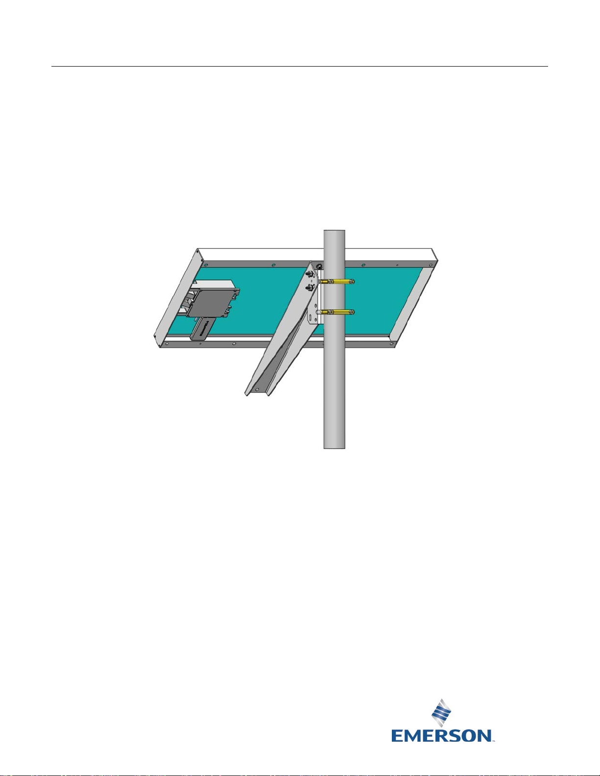
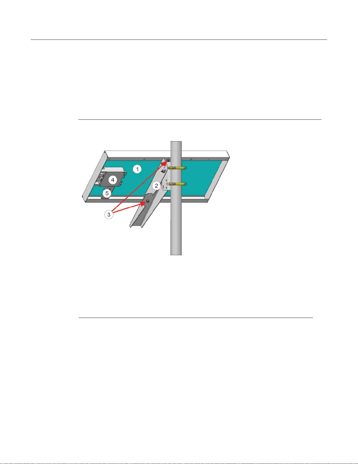
1
Page 5
FB2100/FB2200 Flow Computer 30W Solar Panel Field Replacement Guide
1
30w Solar Panel
2
Adjustable Angle Bracket
3
Hex screws, flat washers, lock washers, hex nuts
4
Junction Box
5
Solar Controller
D301824X012
November 2020
Removing/Replacing the 30W Solar Panel
UL Listed Field Installed Accessory Kit for Use in Class I, Division 2, Groups A, B, C, and D
Flow Computer 30W Solar Panel Field Installed Accessory Kit Part No. 395555-02-7 for Use
with UL Listed Class I, Division 2, Groups A, B, C, and D Model Series FB2100 and FB2200.
The procedure for replacing the 30W solar panel on the FB2100/FB2200 Flow Computer re-uses
the existing mounting hardware provided with the original solar panel. Save any mounting
hardware/screws/nuts/washers from the original.
Components of Solar Panel
1. Disconnect all electrical connections between the flow computer and the solar panel.
2. With a torque wrench, carefully detach the old solar panel (Item 1) from the adjustable angle
bracket (Item 2) by removing the hex screws, washers, and hex nuts (Item 3).
nuts, and washers.
3. Attach the new (replacement) solar panel to the adjustable angle bracket using the saved
hex nuts, washers, and screws.
Save all screws,
4. Torque hex nuts to 50 to 60 in-lbs (5.6 to 6.8 N-m).
5. Apply Loctite
torqueing.
6. Wire connections between the solar panel and the flow computer. (See Removing/Replacing
the Solar Controller)
2
®
222MS Low-Strength Threadlocker sparingly to hex nut threads after
Page 6

FB2100/FB2200 Flow Computer 30W Solar Panel Field Replacement Guide
1
Solar controller
2
Fork connectors
7. Set the tilt angle of the panel for maximum solar exposure. (See Setting the Tilt Angle)
Removing/Replacing the Solar Controller
UL Listed Field Installed Accessory Kit for Use in Class I, Division 2, Groups A, B, C, and D
Flow Computer Solar Controller Field Installed Accessory Kit Part No. 396992-01-3 for Use
with UL Listed Class I, Division 2, Groups A, B, C, D Model Series FB2100 and FB2200.
For the 30W solar panel option with an external solar controller (charger/regulator) purchased
through Emerson, connect the external solar controller to the flow computer battery. If you are
using your own external solar controller, follow the manufacturer’s instructions.
1. If you are using a new solar controller from Emerson, it comes with plastic mounting feet
used only for surface mounting applications. Remove the mounting feet but save the lock
nut.
2. The solar controller also comes with fork connectors.
D301824X012
November 2020
3. Remove the fork connectors and trim back the insulation on the wires ¼ inch.
4. Remove the junction box cover. Use a utility knife to remove the knock-outs (Item 2) in the
junction box (Item 1) and feed the wires from the solar controller into the junction box, and
through the solar controller lock nut (Item 3).
3
Page 7

FB2100/FB2200 Flow Computer 30W Solar Panel Field Replacement Guide
1
Junction Box controller
2
Knock-outs
3
Lock nut
D301824X012
November 2020
5. Use the solar controller lock nut to attach the solar controller to the junction box and use a
7/32” flat head screwdriver to attach the wires from the controller to the junction box
connectors as shown.
4
6. Route the BATT+ and BATT– wires from the flow computer into the junction box.
Page 8

FB2100/FB2200 Flow Computer 30W Solar Panel Field Replacement Guide
1
D301824X012
November 2020
Battery wires from the flow computer
7. Connect the wires as shown. Replace the junction box cover.
Note
Wire in accordance with Article 501.10 (B) of the NEC.
5
Page 9

FB2100/FB2200 Flow Computer 30W Solar Panel Field Replacement Guide
D301824X012
November 2020
6
Page 10

FB2100/FB2200 Flow Computer 30W Solar Panel Field Replacement Guide
1
Tilt angle adjustment (2 of 4 shown)
Adjusting the Tilt Angle
The mounting brackets allow you to adjust the solar panel for maximum solar exposure. You can
adjust the swivel of the panel by adjusting the U-bolt.
To adjust the tilt angle, loosen the four (4) nuts in the adjustable angle bracket and move the panel
to the desired tilt angle. The paragraphs that follow discuss how to choose the tilt angle. When in
the proper position, torque the nuts to 144 to 168 in-lbs (16.3 to 19 N-m) and apply Loctite 222MS
adhesive thread locker sparingly to hex nut threads after torqueing.
Adjusting Solar Panel Tilt Angle
D301824X012
November 2020
1. Point the solar panel surface due south (in the northern hemisphere) or due north (in the
southern hemisphere) at an angle determined by the latitude of the site. The table shows the
angle (from horizontal) at which you should install the solar panel to maximize annual
energy output. At most latitudes, you can improve performance by reducing the angle
during the summer and increasing the angle during the winter. If no seasonal adjustments in
panel direction are needed then adjust the position for the worst-case December-January
angle.
2. Solar insolation is the amount of solar energy in hours received each day by an optimally
tilted panel during the worst month of the year. An insolation rating of one hour means that
the site, on average, would receive one hour of solar energy at the panel's rated power level
(1000W/m2 per day). This rating varies from less than one hour in northern Canada to more
than six hours in the Sahara Desert.
7
Page 11

FB2100/FB2200 Flow Computer 30W Solar Panel Field Replacement Guide
Latitude
Installation Angle
D301824X012
November 2020
Solar Panel Tilt Angle
0 to 4° 10° from horizontal
5 to 20
21 to 45° Add 10° from the local latitude
46 to 65° Add 15° from the local latitude
66 to 75° 80° from horizontal
Add 5° from the local latitude
Removing/Replacing the Solar Controller Cable and Battery Cable
UL Listed Field Installed Accessory Kit for Use in Class I, Division 2, Groups A, B, C, and D
Flow Computer Solar Controller Cable Field Installed Accessory Kit Part No. 396701-03-0 for
Use with UL Listed Class I, Division 2, Groups A, B, C, and D Model Series FB2100 and FB2200.
Flow Computer Battery Cable Field Installed Accessory Kit Part No. 399288-01-0 for Use with
UL Listed Class I, Division 2, Groups A, B, C, and D Model Series FB2100 and FB2200.
There are two cables associated with the solar panel. Both of these cables connect to the BATT
terminals in the flow computer; the battery cable goes to the main battery, the solar controller
cable goes to the solar controller. If necessary, you can replace one or both of these cables.
Reference the wiring graphic on page 6 for the solar controller wiring; reference the wiring graphic
on page 9 for the battery cable wiring.
1. Open the flow computer enclosure.
2. If replacing the battery cable, open the battery compartment by loosening the captive
fastening screws and slide the old battery cable connectors off of the main battery terminals.
3. If replacing the solar controller cable remove the junction box cover at the solar panel and
disconnect the old solar controller cable from the solar controller using a 7/32” flathead
screwdriver and pull it out through the knockout.
4. Use a 1/8” flathead screwdriver to loosen the BATT+ and BATT- terminals on terminal block
TB2 in the flow computer.
8
Page 12

FB2100/FB2200 Flow Computer 30W Solar Panel Field Replacement Guide
D301824X012
November 2020
5. Pull the solar controller cable and battery cable out of the BATT terminals on terminal block
TB2.
6. Attach the replacement cable(s) to the BATT terminals on terminal block TB2. Follow the
wiring guidelines in the flow computer instruction manual and wire the connections as
shown in the wiring graphic on page 6 (for solar cabling) or page 9 (for battery cabling).
7. Close the battery compartment and junction box, then close the flow computer enclosure.
Removing/Replacing the Fuse(s)
Flow Computer Fuse Field Installed Accessory Kit Part No. 395829-01-0 for Use with UL Listed Class
I, Division 2, Groups A, B, C, and D Model Series FB2100 and FB2200.
Reference the wiring graphic on page 9 for the fuse.
1. Open the flow computer enclosure.
2. Gently pull the cable containing the fuse out so you have access to the fuse holder.
3. Grasp the widest part of the fuse holder with your thumb and index finger.
9
Page 13

FB2100/FB2200 Flow Computer 30W Solar Panel Field Replacement Guide
D301824X012
November 2020
4. With the thumb and index finger on your other hand, twist the other end of the fuse holder
counterclockwise to separate the two halves of the fuse holder.
5. Pull out the old fuse and discard it.
6. Put the new fuse in the holder and put the two ends of the holder together.
10
7. Twist the threaded end clockwise until the fuse holder is closed.
Page 14

FB2100/FB2200 Flow Computer 30W Solar Panel Field Replacement Guide
D301824X012
November 2020
8. Press the cable back into the enclosure; ensure it does not get caught in the enclosure door.
9. Close the flow computer enclosure.
11
Page 15

FB2100/FB2200 Flow Computer 30W Solar Panel Field Replacement Guide
D301824X012
November 2020
12
Page 16

FB2100/FB2200 Flow Computer 30W Solar Panel Field Replacement Guide
For customer service and technical support,
Global Headquarters,
North America, and Latin America:
end-user.
Europe:
Middle East/Africa:
Asia-Pacific:
T +65 6777 8211| F +65 6777 0947
D301824X012
November 2020
visit www.Emerson.com/SupportNet
Emerson Automation Solutions
Remote Automation Solutions
6005 Rogerdale Road
Houston, TX 77072 U.S.A.
T +1 281 879 2699 | F +1 281 988 4445
www.Emerson.com/RemoteAutomation
Emerson Automation Solutions
Remote Automation Solutions
Unit 1, Waterfront Business Park
Dudley Road, Brierley Hill
Dudley DY5 1LX UK
T +44 1384 487200 | F +44 1384 487258
Emerson Automation Solutions
Remote Automation Solutions
Emerson FZE
P.O. Box 17033
Jebel Ali Free Zone – South 2
Dubai U.A.E.
T +971 4 8118100 | F +971 4 8865465
Emerson Automation Solutions
Remote Automation Solutions
1 Pandan Crescent
Singapore 128461
© 2018-2020 Remote Automation Solutions, a business unit of Emerson Automation
Solutions. All rights reserved.
This publication is for informational purposes only. While every effort has been made to ensure
accuracy, this publication shall not be read to include any warranty or guarantee, express or
implied, including as regards the products or services described or their use or applicability.
Remote Automation Solutions (RAS) reserves the right to modify or improve the designs or
specifications of its products at any time without notice. All sales are governed by RAS terms
and conditions which are available upon request. RAS accepts no responsibility for proper
selection, use or maintenance of any product, which remains solely with the purchaser and/or
Remote Automation Solutions
 Loading...