

Remote Automation Solutions FB1100/FB1200 Flow Computer Termination Board Field Replacement Guide Manuals & Guides
Page 1
FB1100/FB1200 Flow Computer Termination Board Field Replacement Guide
FB1100/FB1200 Flow Computer
Termination Board
Field Replacement Guide
D301820X012
November 2020
For Part Numbers (Kits):
399185-01-1
400216010-KIT
395791014-KIT
395803000-KIT
Remote Automation Solutions
Page 2

FB1100/FB1200 Flow Computer Termination Board Field Replacement Guide
D301820X012
November 2020
Device Safety Considerations
Reading these Instructions
Before operating the device, read these instructions carefully and understand their safety implications. In some situations,
improperly using this device may result in damage or injury. Keep this manual in a convenient location for future reference.
Note that these instructions may not cover all details or variations in equipment or cover every possible situation regarding
installation, operation, or maintenance. Should problems arise that are not covered sufficiently in the text, immediately
contact Customer Support for further information.
Protecting Operating Processes
A failure of this device – for whatever reason -- may leave an operating process without appropriate protection and could result
in possible damage to property or injury to persons. To protect against this, you should review the need for additional backup
equipment or provide alternate means of protection (such as alarm devices, output limiting, fail-safe valves, relief valves,
emergency shutoffs, emergency switches, etc.). Contact Remote Automation Solutions for additional information.
Returning Equipment
If you need to return any equipment to Remote Automation Solutions, it is your responsibility to ensure that the equipment
has been cleaned to safe levels, as defined and/or determined by applicable federal, state and/or local law regulations or
codes. You also agree to indemnify Remote Automation Solutions and hold Remote Automation Solutions harmless from any
liability or damage which Remote Automation Solutions may incur or suffer due to your failure to ensure device cleanliness.
Grounding Equipment
Ground metal enclosures and exposed metal parts of electrical instruments in accordance with OSHA rules and regulations as
specified in Design Safety Standards for Electrical Systems, 29 CFR, Part 1910, Subpart S, dated: April 16, 1981 (OSHA rulings are
in agreement with the National Electrical Code). You must also ground mechanical or pneumatic instruments that include
electrically operated devices such as lights, switches, relays, alarms, or chart drives.
Important: Complying with the codes and regulations of authorities having jurisdiction is essential to ensuring personnel
safety. The guidelines and recommendations in this manual are intended to meet or exceed applicable codes and regulations.
If differences occur between this manual and the codes and regulations of authorities having jurisdiction, those codes and
regulations must take precedence.
Protecting from Electrostatic Discharge (ESD)
This device contains sensitive electronic components which be damaged by exposure to an ESD voltage. Depending on the
magnitude and duration of the ESD, it can result in erratic operation or complete failure of the equipment. Ensure that you
correctly care for and handle ESD-sensitive components.
System Training
A well-trained workforce is critical to the success of your operation. Knowing how to correctly install, configure, program,
calibrate, and trouble-shoot your Emerson equipment provides your engineers and technicians with the skills and confidence
to optimize your investment. Remote Automation Solutions offers a variety of ways for your personnel to acquire essential
system expertise. Our full-time professional instructors can conduct classroom training at several of our corporate offices, at
your site, or even at your regional Emerson office. You can also receive the same quality training via our live, interactive
Emerson Virtual Classroom and save on travel costs. For our complete schedule and further information, contact the Remote
Automation Solutions Training Department at 800-338-8158 or email us at education@emerson.com.
Ethernet Connectivity
This automation device is intended to be used in an Ethernet network which does not have public access. The inclusion of this
device in a publicly accessible Ethernet-based network is not recommended.
Page 3
FB1100/FB1200 Flow Computer Termination Board Field Replacement Guide
CAUTION
Removing/Replacing Termination Boards
MAY CAUSE INJURY TO PERSONNEL OR DAMAGE EQUIPMENT
Because I/O, ground, and other wires enter the flow computer through conduit fittings and
then connect to the termination board, a qualified technician must disconnect all wiring
coming into the flow computer and pull it out through the conduit fittings in order to replace
the termination board.
You must then install the new termination board and completely rewire the unit.
If not already done, be sure to label all wires before disconnecting so you can identify them
later during the rewiring process.
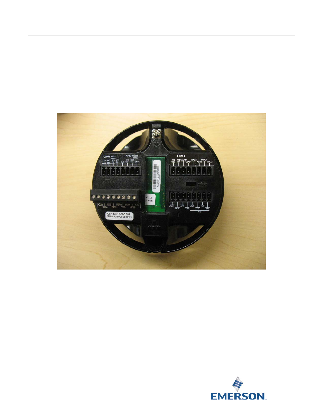
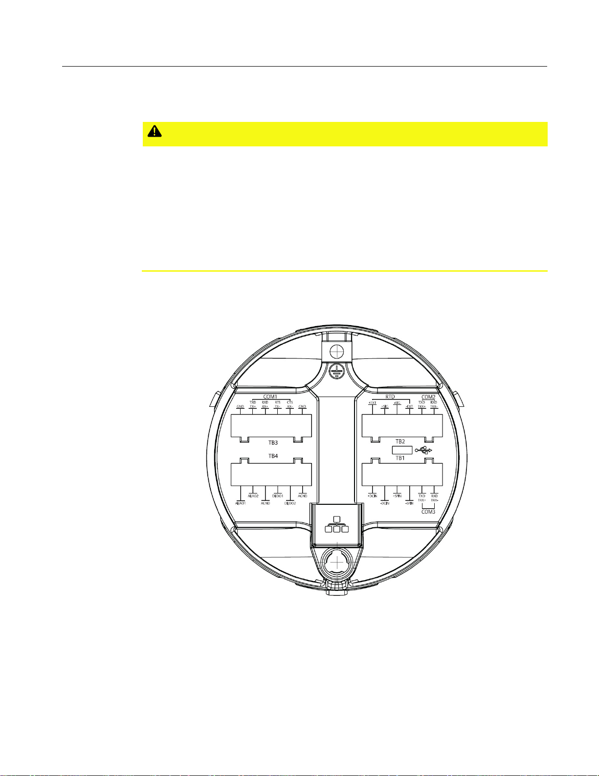
The FB1100 Flow Computer includes a single type of termination board that uses 6-connector
pluggable terminal blocks.
D301820X012
November 2020
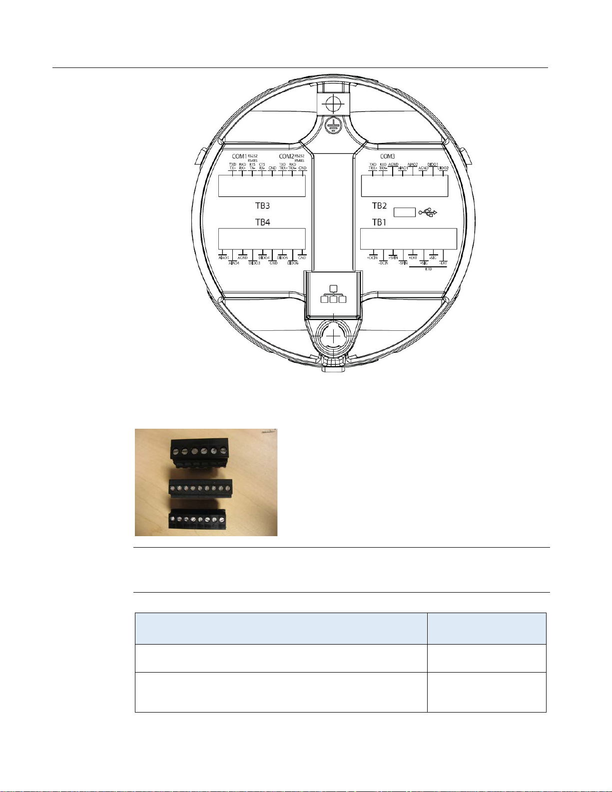
The FB1200 Flow Computer supports the same termination board and blocks. In addition, if the
FB1200 Flow Computer is purchased with the 6-channel expansion I/O board, it uses a different
termination board with 8 (or in one case 9) connector pluggable terminal blocks.
1
Page 4
FB1100/FB1200 Flow Computer Termination Board Field Replacement Guide
Item
Field Replacement Kit
Part Number
400216010-KIT
D301820X012
November 2020
The basic methods for replacing termination boards or for replacing termination blocks are the
same. The only differences occur in the number of connectors on a terminal block used on a
termination board.
Restriction
Hazardous area approvals require that any part replaced in the field be the exact same part (“likefor-like”). Upgrading or substituting different parts violates hazardous area certification.
Refer to the table below for the correct field replacement kit part number.
Termination Board (used with 6-connector pluggable terminal
399185-01-1
blocks)
Termination Board (used with 8-connector pluggable terminal
blocks on any FB1200 Flow Computer which has a 6-channel
expansion I/O board)
2
Page 5
FB1100/FB1200 Flow Computer Termination Board Field Replacement Guide
Item
Field Replacement Kit
Part Number
395803000-KIT
WARNING
WARNING
WARNING
D301820X012
November 2020
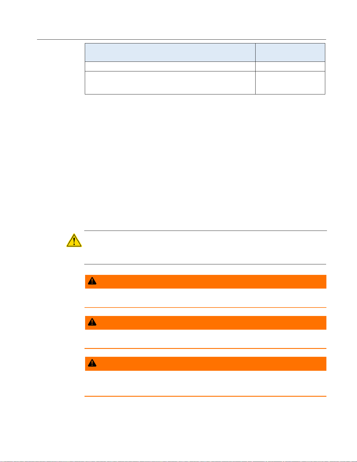
6-connector pluggable terminal blocks (pack of 4) 395791014-KIT
8-connector pluggable terminal blocks (pack of 4) – (Used with
any FB1200 Flow Computer which has a 6-channel expansion I/O
board)
Ambient Temperature Range
May be used up to a maximum ambient temperature of 80˚C and a minimum ambient
temperature of -40˚C; see product data plate (on device) for ambient temperature.
Required Tools
#1 Phillips-head screwdriver
#2 Phillips-head screwdriver
3/32-inch flat head screwdriver (for 3.81 mm pitch terminal block connections)
1/8-inch flat-head screwdriver (for 5.08 pitch terminal block connections)
3mm hexagonal torque wrench. Ranges must cover 10 to 12 in-lbs (1.1 to 1.4 N-m).
Electrical Ratings
I/O Ratings (FB1200 Flow Computer):
o
4 Digital Outputs: 0.5A, 24Vdc
o
2 Analog Outputs: 4-20 mA
Important
Only use accessories supplied with the flow computer or sold by Emerson as spare parts for this
flow computer. Substituting a part you obtain elsewhere (such as a battery)
certification.
EXPLOSION HAZARD – Substitution of any components may impair suitability for Class I,
Division 1 or Class I, Division 2.
Do not disconnect equipment unless power has been removed or the area is known to be nonhazardous.
voids your approval
EXPLOSION HAZARD – Do not replace batteries unless power has been switched off or the
area is known to be non-hazardous. Batteries must only be changed in an area known to be
non-hazardous.
3
Page 6
FB1100/FB1200 Flow Computer Termination Board Field Replacement Guide
DANGER
DANGER
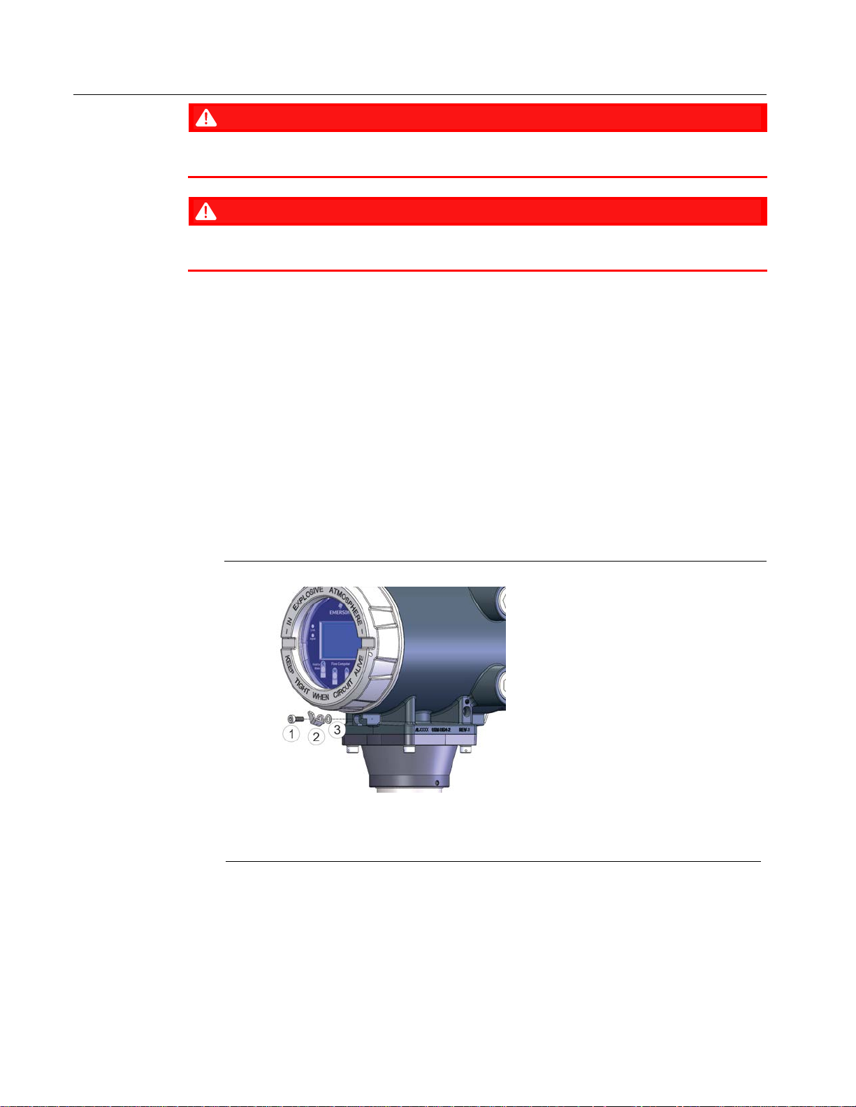
1
Screw
2
Reta
3
Washer
D301820X012
November 2020
EXPLOSION HAZARD: Ensure the area in which you perform this operation is non-hazardous.
Performing this operation in a hazardous area could result in an explosion.
EXPLOSION HAZARD: Never remove end cap(s) in a hazardous location. Removing cover(s) in a
hazardous location could result in an explosion.
Removing/Replacing the HMI Module
UL Listed Termination Board Field Installed Accessory Kit for Use in Class I, Division 1, Groups C,
D; Class I, Division 2, Groups A, B, C, and D
Flow Computer Termination Board Field Installed Accessory Kit Part No. 399185-01-1 for
use with UL Listed Model Series FB1100.
Flow Computer Termination Board Field Installed Accessory Kit Part No. 400216010-KIT
for use with UL Listed Model Series FB1200.
To replace the termination board, you first need to remove the battery enclosure/HMI module
assembly to gain access to the termination board screws on the inside of the flow computer.
1. Remove the front and rear end caps. Remove the retaining clamp on the front end cap (if
present) using a 3 mm hexagonal wrench.
Components of Retaining Clamp Assembly
ining Clamp
2. Grasp the end cap (front or rear).
4
Page 7

FB1100/FB1200 Flow Computer Termination Board Field Replacement Guide
D301820X012
November 2020
Front End Cap Rear End Caps
3. Unscrew the end cap turning it counter-clockwise until the cover comes off. Set it aside in
a safe location.
Note
If you need more leverage place a long screwdriver or other appropriate tool across the
two notches in the cover to act as a pry bar.
Front End Cap (unscrewed) Rear End Cap (unscrewed)
Important
When replacing the rear end cap, ensure wires connecting to the terminal plate do not
get crimped or caught between the end cap threads and the enclosure.
4. Disconnect power at terminal TB1 on the termination board.
5. Disconnect all terminal blocks and disconnect all wires (I/O, grounding, communications)
coming into the flow computer.
6. With a #2 Phillips-head screwdriver loosen the two captive fastening screws on the battery
pack enclosure.
5
Page 8

FB1100/FB1200 Flow Computer Termination Board Field Replacement Guide
D301820X012
November 2020
Captive Fastening Screws
7. With a #1 Phillips-head screwdriver, loosen the two bottom captive fastening screws on
the HMI module. Leave the two top screws on the HMI module connected to the battery
pack enclosure.
8. Grasp the HMI module and gently pull it and the battery pack enclosure out of the
housing.
6
Page 9

FB1100/FB1200 Flow Computer Termination Board Field Replacement Guide
D301820X012
November 2020
9. If the battery pack enclosure holds an internal battery, disconnect the battery connector.
10. Set the battery pack enclosure/HMI module assembly.
11. Look into the housing from the front. Two captive fastening screws on the inside of the
housing hold the termination board in place.
7
Page 10

FB1100/FB1200 Flow Computer Termination Board Field Replacement Guide
D301820X012
November 2020
12. With a #2 Phillips-head screwdriver loosen the two captive fastening screws.
13. Now grasp the termination board bezel from the back of the unit and pull out the
termination board assembly.
8
Page 11

FB1100/FB1200 Flow Computer Termination Board Field Replacement Guide
D301820X012
November 2020
14. You should be able to see through the housing from back to front and see the opposite
end of the captive fastening screws that you saw in Steps 11 and 12.
15. Take the new (replacement) termination board (399185-01-1 or 400216010-KIT) and
align it with the captive fastening screw holes and press it into the back of the housing
onto the captive fastening screws.
9
Page 12

FB1100/FB1200 Flow Computer Termination Board Field Replacement Guide
D301820X012
November 2020
16. Tighten the screws that you loosened in Step 12. Torque screws to 6 in-lbs (0.7 N-m).
17. Take the battery pack enclosure/HMI module assembly you removed in Step 8. Being
careful to keep the battery wire and its connector free, carefully slide the assembly into
the front of the housing so that the HMI module mates with the green and yellow
connector from the CPU module. Tighten the screws to hold the assembly in place.
Torque screws to 6 in-lbs (0.7 N-m). If battery-powered, re-connect the battery.
18. You can now proceed to rewire all connections (I/O, communications, grounding) to the
flow computer. Please refer to the instruction manual for wiring installation instructions.
Removing/Replacing Pluggable Terminal Blocks
UL Listed Terminal Block Field Installed Accessory Kit for Use in Class I, Division 1, Groups C, D;
Class I, Division 2, Groups A, B, C, D
Flow Computer 6-connector pluggable terminal block Field Installed Accessory Kit Part
No. 395791014-KIT for use with UL Listed Model Series FB1100.
Flow Computer 8-connector pluggable terminal block Field Installed Accessory Kit Part
No. 395803000-KIT for use with UL Listed Model Series FB1200.
If one or more terminal blocks becomes damaged, you may need to replace them.
For 6-connector terminal blocks you need a 1/8 inch flat head screwdriver.
10
For 8-connector (or 9-connector) terminal blocks you need a 3/32 inch flat head
screwdriver.
Page 13

FB1100/FB1200 Flow Computer Termination Board Field Replacement Guide
1
Screw
2
Retaining Clamp
3
Washer
D301820X012
November 2020
Tip
If you have more than one terminal block to replace, we recommend you replace one
terminal block at a time to avoid confusion.
1. Remove the rear end cap by first removing the retaining clamp on the end cap (if present)
using a 3 mm hexagonal wrench.
Components of Retaining Clamp Assembly (front clamp shown) Rear End Cap
2. Grasp the end cap.
Rear End Cap
3. Unscrew the end cap turning it counter-clockwise until the cover comes off. Set it aside in
a safe location.
11
Page 14

FB1100/FB1200 Flow Computer Termination Board Field Replacement Guide
D301820X012
November 2020
Note
If you need more leverage place a long screwdriver or other appropriate tool across the
two notches in the cover to act as a pry bar.
Rear End Cap Removal
4. Remove power at terminal block TB1.
5. If your unit doesn’t include an internal battery, skip to Step 8. If the unit has an internal
battery which is connected, use a #1 Phillips-head screwdriver to loosen the four captive
fastening screws on the HMI module.
Captive Fastening Screws
12
6. Grasp the HMI module and remove it by gently pulling it straight out.
7. If battery-powered, disconnect the internal battery.
Page 15

FB1100/FB1200 Flow Computer Termination Board Field Replacement Guide
D301820X012
November 2020
8. For the terminal block you want to replace, make sure you note which wire goes to which
terminal. If they aren’t labeled, you should label them, or take a digital photo so you know
which wire goes to which connector of the terminal block.
9. Place your fingers on each of the short sides of the terminal block and gently rock it back
and forth so it pops out of the termination board.
10. Use a flat head screwdriver to loosen the screw for each wire coming into the old terminal
block. Slide the same wire into the identical position on the new
block and tighten the screw to hold it in place. Repeat for each wire.
11. Repeat steps 8 through 10 for each terminal block you want to replace.
12. If you have an internal battery, you can re-connect it now, and put the HMI module back
on. To replace the HMI module, line up the printed circuit board (PCB) with the slot on the
back of the replacement module and gently press the new HMI module on. Tighten the
four captive fastening screws with a torque of 6 in-lbs (0.7 N-m).
(replacement) terminal
13
Page 16

FB1100/FB1200 Flow Computer Termination Board Field Replacement Guide
D301820X012
November 2020
13. You can now plug your new terminal blocks back into the termination board, leaving TB1
last for when you want to restore power.
14. Carefully align the end cap threads with the threads of the enclosure and replace the rear
end cap. Screw the end cap clockwise (eight full turns) until it is tightly sealed to the
enclosure. Endcaps must have at least 8 full threads engaged upon reassembly.
Note
If you need more leverage place a long screwdriver or other appropriate tool across the two
notches in the cover to act as a pry bar.
15. If applicable, tighten the retaining clamp using the screw and washer onto the end cap
using a 3mm hexagonal wrench. When tightening, torque to 10 to 12 in-lbs (1.1 to 1.4
N-m).
14
Page 17

FB1100/FB1200 Flow Computer Termination Board Field Replacement Guide
D301820X012
November 2020
15
Page 18

FB1100/FB1200 Flow Computer Termination Board Replacement Guide
For customer service and technical support,
Global Headquarters,
North America, and Latin America:
end-user.
Europe:
Middle East/Africa:
Asia-Pacific:
T +65 6777 8211| F +65 6777 0947
D301820X012
November 2020
visit www.Emerson.com/SupportNet
Emerson Automation Solutions
Remote Automation Solutions
6005 Rogerdale Road
Houston, TX 77072 U.S.A.
T +1 281 879 2699 | F +1 281 988 4445
www.Emerson.com/RemoteAutomation
Emerson Automation Solutions
Remote Automation Solutions
Unit 1, Waterfront Business Park
Dudley Road, Brierley Hill
Dudley DY5 1LX UK
T +44 1384 487200 | F +44 1384 487258
Emerson Automation Solutions
Remote Automation Solutions
Emerson FZE
P.O. Box 17033
Jebel Ali Free Zone – South 2
Dubai U.A.E.
T +971 4 8118100 | F +971 4 8865465
Emerson Automation Solutions
Remote Automation Solutions
1 Pandan Crescent
Singapore 128461
© 2018-2020 Remote Automation Solutions, a business unit of Emerson Automation
Solutions. All rights reserved.
This publication is for informational purposes only. While every effort has been made to ensure
accuracy, this publication shall not be read to include any warranty or guarantee, express or
implied, including as regards the products or services described or their use or applicability.
Remote Automation Solutions (RAS) reserves the right to modify or improve the designs or
specifications of its products at any time without notice. All sales are governed by RAS terms
and conditions which are available upon request. RAS accepts no responsibility for proper
selection, use or maintenance of any product, which remains solely with the purchaser and/or
Remote Automation Solutions
 Loading...