

Remote Automation Solutions FB1100/FB1200 Flow Computer Sensor Assembly Field Replacement Guide Manuals & Guides
Page 1

FB1100/FB1200 Flow Computer Sensor Assembly Field Replacement Guide
FB1100/FB1200 Flow Computer
Sensor Assembly
Field Replacement Guide
D301842X012
November 2020
For Part Numbers (Kits):
See tables on pages iii through v for part/kit numbers
Remote Automation Solutions
Page 2

FB1100/FB1200 Flow Computer Sensor Assembly Field Replacement Guide
D301842X012
November 2020
Device Safety Considerations
Reading these Instructions
Before operating the device, read these instructions carefully and understand their safety implications. In some situations,
improperly using this device may result in damage or injury. Keep this manual in a convenient location for future reference.
Note that these instructions may not cover all details or variations in equipment or cover every possible situation regarding
installation, operation, or maintenance. Should problems arise that are not covered sufficiently in the text, immediately
contact Customer Support for further information.
Protecting Operating Processes
A failure of this device – for whatever reason -- may leave an operating process without appropriate protection and could result
in possible damage to property or injury to persons. To protect against this, you should review the need for additional backup
equipment or provide alternate means of protection (such as alarm devices, output limiting, fail-safe valves, relief valves,
emergency shutoffs, emergency switches, etc.). Contact Remote Automation Solutions for additional information.
Returning Equipment
If you need to return any equipment to Remote Automation Solutions, it is your responsibility to ensure that the equipment
has been cleaned to safe levels, as defined and/or determined by applicable federal, state and/or local law regulations or
codes. You also agree to indemnify Remote Automation Solutions and hold Remote Automation Solutions harmless from any
liability or damage which Remote Automation Solutions may incur or suffer due to your failure to ensure device cleanliness.
Grounding Equipment
Ground metal enclosures and exposed metal parts of electrical instruments in accordance with OSHA rules and regulations as
specified in Design Safety Standards for Electrical Systems, 29 CFR, Part 1910, Subpart S, dated: April 16, 1981 (OSHA rulings are
in agreement with the National Electrical Code). You must also ground mechanical or pneumatic instruments that include
electrically operated devices such as lights, switches, relays, alarms, or chart drives.
Important: Complying with the codes and regulations of authorities having jurisdiction is essential to ensuring personnel
safety. The guidelines and recommendations in this manual are intended to meet or exceed applicable codes and regulations.
If differences occur between this manual and the codes and regulations of authorities having jurisdiction, those codes and
regulations must take precedence.
Protecting from Electrostatic Discharge (ESD)
This device contains sensitive electronic components which be damaged by exposure to an ESD voltage. Depending on the
magnitude and duration of the ESD, it can result in erratic operation or complete failure of the equipment. Ensure that you
correctly care for and handle ESD-sensitive components.
System Training
A well-trained workforce is critical to the success of your operation. Knowing how to correctly install, configure, program,
calibrate, and trouble-shoot your Emerson equipment provides your engineers and technicians with the skills and confidence
to optimize your investment. Remote Automation Solutions offers a variety of ways for your personnel to acquire essential
system expertise. Our full-time professional instructors can conduct classroom training at several of our corporate offices, at
your site, or even at your regional Emerson office. You can also receive the same quality training via our live, interactive
Emerson Virtual Classroom and save on travel costs. For our complete schedule and further information, contact the Remote
Automation Solutions Training Department at 800-338-8158 or email us at education@emerson.com.
Ethernet Connectivity
This automation device is intended to be used in an Ethernet network which does not have public access. The inclusion of this
device in a publicly accessible Ethernet-based network is not recommended.
ii
Page 3

FB1100/FB1200 Flow Computer Sensor Assembly Field Replacement Guide
Integral Sensor
Selection
Differential Pressure Range & Accuracy
25 Inches H2O (62.3 mbar) DP, 0.1% Accuracy
Notes:
Available only with stainless steel sensor & coplanar flange.
Class 1 Div 2 UL, IEC Ex N, ATEX Ex N
250 Inches H2O (623 mbar) DP, 0.1% Accuracy
Note: 0.1% Accuracy is not available on Traditional Flange.
Class 1 Div 2 UL, IEC Ex N, ATEX Ex N
Class 1 Div 1 UL, IEC Ex d, ATEX Ex d
250 Inches H2O (623 mbar) DP, 0.075% Accuracy
Class 1 Div 2 UL, IEC Ex N, ATEX Ex N
Class 1 Div 1 UL, IEC Ex d, ATEX Ex d
1000 Inches H2O (2.5 bar) DP, 0.1% Accuracy
Notes:
1000" DP range not available with 300 psi static pressure.
Class 1 Div 2 UL, IEC Ex N, ATEX Ex N
1000 Inches H2O (2.5 bar) DP, 0.075% Accuracy
Note: 1000" DP range not available with 300 psi static pressure.
Class 1 Div 2 UL, IEC Ex N, ATEX Ex N
Class 1 Div 1 UL, IEC Ex d, ATEX Ex d
Static Pressure Range - for use with Multivariable Sensor (B22* or B12* above)
MV 300 psi gauge (20.7 barg)
Note: 1000" DP range not available with 300 psi static pressure.
Class 1 Div 2 UL, IEC Ex N, ATEX Ex N
Class 1 Div 1 UL, IEC Ex d, ATEX Ex d
MV 300 psi absolute (20.7 bara)
Note: 1000" DP range not available with 300 psi static pressure.
Class 1 Div 2 UL, IEC Ex N, ATEX Ex N
Class 1 Div 1 UL, IEC Ex d, ATEX Ex d
Class 1 Div 2 UL, IEC Ex N, ATEX Ex N
Class 1 Div 1 UL, IEC Ex d, ATEX Ex d
Class 1 Div 2 UL, IEC Ex N, ATEX Ex N
Class 1 Div 1 UL, IEC Ex d, ATEX Ex d
MV 3600 psi gauge (250 barg)
Note:
is 2000 psi/137.9 Bar.
Class 1 Div 2 UL, IEC Ex N, ATEX Ex N
MV 3600 psi absolute (250 bara)
Note:
is 2000 psi/137.9 Bar.
Class 1 Div 2 UL, IEC Ex N, ATEX Ex N
Sensor Material & Flange Type
Class 1 Div 2 UL, IEC Ex N, ATEX Ex N
Class 1 Div 1 UL, IEC Ex d, ATEX Ex d
Hastelloy Diaphragm and Hastelloy Coplanar Flange
Note:
sensor.
Class 1 Div 2 UL, IEC Ex N, ATEX Ex N
Note:
Class 1 Div 2 UL, IEC Ex N, ATEX Ex N
Class 1 Div 1 UL, IEC Ex d, ATEX Ex d
Sensor Material Certificates
Class 1 Div 2 UL, IEC Ex N, ATEX Ex N
Class 1 Div 1 UL, IEC Ex d, ATEX Ex d
Class 1 Div 2 UL, IEC Ex N, ATEX Ex N
Class 1 Div 1 UL, IEC Ex d, ATEX Ex d
NACE MRO 175/ISO 15156 requires Hastelloy Diaphragm
Note: Available only with 3E13.
Class 1 Div 2 UL, IEC Ex N, ATEX Ex N
NACE MRO 103 - requires Hastelloy Diaphragm Option
Note:
Class 1 Div 2 UL, IEC Ex N, ATEX Ex N
Class 1 Div 1 UL, IEC Ex d, ATEX Ex d
D301842X012
November 2020
Table 1. FB1100 Sensor Assembly Part Numbers (Use Selection Column to Generate UL-listed Kit Number)
Approvals
0.1% Accuracy is not available on Traditional Flange.
25" DP option is available only with static pressure options G4
or A4 and the maximum pressure is limited to 2000 psi.
0.1% Accuracy is not available on Traditional Flange.
1000" DP range with 0.1% accuracy available only with
Stainless steel sensor and coplanar flange.
MV 1500 psi gauge (103.4 barg)
MV 1500 psi absolute (103.4 bara)
Class 1 Div 1 UL, IEC Ex d, ATEX Ex d
B221
B222
B122
Class 1 Div 1 UL, IEC Ex d, ATEX Ex d
B223
B123
G6
A6
G7
A7
When used with 25" DP option, maximum working pressure
When used with 25" DP option, maximum working pressure
Class 1 Div 1 UL, IEC Ex d, ATEX Ex d
Class 1 Div 1 UL, IEC Ex d, ATEX Ex d
Stainless Steel Sensor and Coplanar Flange
Not available with a 1000" 0.1% accuracy sensor or a 25"
Class 1 Div 1 UL, IEC Ex d, ATEX Ex d
Stainless Steel Sensor and Traditional Flange
0.1% Accuracy is not available on Traditional Flange.
Not Required
3.1 B Traceability certs to EN 10205
Option
Available only with 3E13.
Class 1 Div 1 UL, IEC Ex d, ATEX Ex d
G4
A4
2E12
3E13
2F12
Q0R
Q8R
Q15R
Q25R
iii
Page 4

FB1100/FB1200 Flow Computer Sensor Assembly Field Replacement Guide
Integral Sensor
Selection
Calibration Certificate
Class 1 Div 2 UL, IEC Ex N, ATEX Ex N
Class 1 Div 1 UL, IEC Ex d, ATEX Ex d
Class 1 Div 2 UL, IEC Ex N, ATEX Ex N
Class 1 Div 1 UL, IEC Ex d, ATEX Ex d
Integral Sensor
Selection
Differential Pressure Range & Accuracy
Approvals
25 Inches H2O (62.3 mbar) DP, 0.1% Accuracy
Notes:
Class 1 Div 2 UL, IEC Ex N, ATEX Ex N
250 Inches H2O (623 mbar) DP, 0.1% Accuracy
Note: 0.1% Accuracy is not available on Traditional Flange.
Class 1 Div 2 UL, IEC Ex N, ATEX Ex N
Class 1 Div 1 UL, IEC Ex d, ATEX Ex d
250 Inches H2O (623 mbar) DP, 0.075% Accuracy
Class 1 Div 2 UL, IEC Ex N, ATEX Ex N
Class 1 Div 1 UL, IEC Ex d, ATEX Ex d
1000 Inches H2O (2.5 bar) DP, 0.1% Accuracy
Notes
pressure.
Class 1 Div 2 UL, IEC Ex N, ATEX Ex N
1000 Inches H2O (2.5 bar) DP, 0.075% Accuracy
Note
pressure.
Class 1 Div 2 UL, IEC Ex N, ATEX Ex N
No Differential Pressure Required, Static Pressure only
Note: Available only with inline sensor option (2K11)
Class 1 Div 2 UL, IEC Ex N, ATEX Ex N
No Differential Pressure Required, Static Pressure only,
Note: Available only with inline sensor option (2K11)
Class 1 Div 2 UL, IEC Ex N, ATEX Ex N
Static Pressure Range - for use with Multivariable Sensor (B22* or B12* above)
MV 300 psi gauge (20.7 barg)
Note
pressure.
Class 1 Div 2 UL, IEC Ex N, ATEX Ex N
MV 300 psi absolute (20.7 bara)
Note
pressure.
Class 1 Div 2 UL, IEC Ex N, ATEX Ex N
Class 1 Div 2 UL, IEC Ex N, ATEX Ex N
Class 1 Div 1 UL, IEC Ex d, ATEX Ex d
D301842X012
November 2020
Not Required
Required
Example Model Number:
Stainless Steel Sensor and Coplanar Flange, No Sensor Material Certificates Required, and Calibration Certificate
Required.
Table 2. FB1200 Sensor Assembly Part Numbers (Use Selection Column to Generate UL-listed Kit Number)
0.1% Accuracy is not available on Traditional Flange.
25" DP option is available only with static pressure
options G4 or A4 and the maximum pressure is limited
to 2000 psi.
Available only with stainless steel sensor & coplanar
flange.
B222G72E12Q0RM4
= 250 Inches H2O (623 mbar) DP, 0.1% Accuracy, MV 1500 psi gauge,
Class 1 Div 1 UL, IEC Ex d, ATEX Ex d
B221
B222
B122
M0
M4
:
0.1% Accuracy is not available on Traditional Flange.
1000" DP range with 0.1% accuracy available only with
Stainless steel sensor and coplanar flange.
1000" DP range not available with 300 psi static
: 1000" DP range not available with 300 psi static
accuracy 0.1%
accuracy 0.075%
: 1000" DP range not available with 300 psi static
: 1000" DP range not available with 300 psi static
MV 1500 psi gauge (103.4 barg)
Class 1 Div 1 UL, IEC Ex d, ATEX Ex d
B223
Class 1 Div 1 UL, IEC Ex d, ATEX Ex d B123
Class 1 Div 1 UL, IEC Ex d, ATEX Ex d B2
Class 1 Div 1 UL, IEC Ex d, ATEX Ex d B1
Class 1 Div 1 UL, IEC Ex d, ATEX Ex d G6
Class 1 Div 1 UL, IEC Ex d, ATEX Ex d A6
G7
iv
Page 5

FB1100/FB1200 Flow Computer Sensor Assembly Field Replacement Guide
Integral Sensor
Selection
Class 1 Div 2 UL, IEC Ex N, ATEX Ex N
Class 1 Div 1 UL, IEC Ex d, ATEX Ex d
MV 3600 psi gauge (250 barg)
Note
pressure is 2000 psi/137.9 Bar.
Class 1 Div 2 UL, IEC Ex N, ATEX Ex N
MV 3600 psi absolute (250 bara)
Note
pressure is 2000 psi/137.9 Bar.
Class 1 Div 2 UL, IEC Ex N, ATEX Ex N
Static Pressure Range - for use only with Static Pressure Sensor (B1 or B2 above)
Class 1 Div 2 UL, IEC Ex N, ATEX Ex N
Class 1 Div 1 UL, IEC Ex d, ATEX Ex d
Class 1 Div 2 UL, IEC Ex N, ATEX Ex N
Class 1 Div 1 UL, IEC Ex d, ATEX Ex d
Class 1 Div 2 UL, IEC Ex N, ATEX Ex N
Class 1 Div 1 UL, IEC Ex d, ATEX Ex d
Class 1 Div 2 UL, IEC Ex N, ATEX Ex N
Class 1 Div 1 UL, IEC Ex d, ATEX Ex d
Class 1 Div 2 UL, IEC Ex N, ATEX Ex N
Class 1 Div 1 UL, IEC Ex d, ATEX Ex d
Class 1 Div 2 UL, IEC Ex N, ATEX Ex N
Class 1 Div 1 UL, IEC Ex d, ATEX Ex d
Sensor Material & Flange Type
Class 1 Div 2 UL, IEC Ex N, ATEX Ex N
Class 1 Div 1 UL, IEC Ex d, ATEX Ex d
Hastelloy Diaphragm and Hastelloy Coplanar Flange
Note
25" sensor.
Class 1 Div 2 UL, IEC Ex N, ATEX Ex N
Stainless Steel Sensor and Traditional Flange
Note: 0.1% Accuracy is not available on Traditional Flange.
Class 1 Div 2 UL, IEC Ex N, ATEX Ex N
Class 1 Div 1 UL, IEC Ex d, ATEX Ex d
Stainless Steel inline connection 1/2" 14 NPT Female - use
with Static Pressure only option B1 or B2 above
Class 1 Div 2 UL, IEC Ex N, ATEX Ex N
Class 1 Div 1 UL, IEC Ex d, ATEX Ex d
Sensor Material Certificates
Class 1 Div 2 UL, IEC Ex N, ATEX Ex N
Class 1 Div 1 UL, IEC Ex d, ATEX Ex d
Class 1 Div 2 UL, IEC Ex N, ATEX Ex N
Class 1 Div 1 UL, IEC Ex d, ATEX Ex d
NACE MRO 175/ISO 15156 requires Hastelloy Diaphragm
Note: Available only with 3E13.
Class 1 Div 2 UL, IEC Ex N, ATEX Ex N
NACE MRO 103 - requires Hastelloy Diaphragm Option
Note: Available only with 3E13.
Class 1 Div 2 UL, IEC Ex N, ATEX Ex N
Class 1 Div 1 UL, IEC Ex d, ATEX Ex d
Calibration Certificate
Class 1 Div 2 UL, IEC Ex N, ATEX Ex N
Class 1 Div 1 UL, IEC Ex d, ATEX Ex d
Class 1 Div 2 UL, IEC Ex N, ATEX Ex N
Class 1 Div 1 UL, IEC Ex d, ATEX Ex d
D301842X012
November 2020
MV 1500 psi absolute (103.4 bara)
: When used with 25" DP option, maximum working
: When used with 25" DP option, maximum working
SP 150 psi gauge (10.34 barg)
SP 150 psi absolute (10.34 bara)
SP 800 psi gauge (55.15 barg)
SP 800 psi absolute (55.15 bara)
SP 4000 psi gauge (275.79 barg)
SP 4000 psi absolute (275.79 bara)
Stainless Steel Sensor and Coplanar Flange
A7
Class 1 Div 1 UL, IEC Ex d, ATEX Ex d G4
Class 1 Div 1 UL, IEC Ex d, ATEX Ex d A4
G2
A2
G3
A3
G4
A4
2E12
: Not available with a 1000" 0.1% accuracy sensor or a
Not Required
3.1 B Traceability certs to EN 10205
Option
Not Required
Required
Example Model Number: B222G72E12Q0RM4 - 250 Inches H2O (623 mbar) DP, 0.1% Accuracy, MV 1500 psi gauge,
Stainless Steel Sensor and Coplanar Flange, No Sensor Material Certificates Required, and Calibration Certificate
Required.
Class 1 Div 1 UL, IEC Ex d, ATEX Ex d 3E13
2F12
2K11
Q0R
Q8R
Class 1 Div 1 UL, IEC Ex d, ATEX Ex d Q15R
Q25R
M0
M4
v
Page 6

FB1100/FB1200 Flow Computer Sensor Assembly Field Replacement Guide
D301842X012
November 2020
vi
Page 7

FB1100/FB1200 Flow Computer Sensor Assembly Field Replacement Guide
DANGER
CAUTION
MAY CAUSE INJURY TO PERSONNEL OR DAMAGE EQUIPMENT
Removing/Replacing Sensor Assemblies
D301842X012
November 2020
EXPLOSION HAZARD: To replace the sensor you must completely remove the flow computer
from its installation location and move it to a non-hazardous area. Ensure the area is nonhazardous before disconnecting the flow computer.
Because I/O, ground, and other wires enter the flow computer through conduit fittings and then
connect to the boards inside, a qualified technician must disconnect all wiring coming into the
flow computer and pull it out through the conduit fittings in order to replace the sensor
assembly.
You must then reinstall all boards and modules and completely rewire the unit.
If not already done, be sure to label all wires before disconnecting so you can identify them later
during the rewiring process.
Field Replacement Kit Part Numbers
Refer to Table 1 (for FB1100) or Table 2 (for FB1200) on pages iii through v to determine the
correct field replacement kit part number.
Required Tools
#1 Phillips-head screwdriver
#2 Phillips-head screwdriver
3/32-inch flat head screwdriver (for 3.81 mm pitch terminal block connections on FB1200
Flow Computer with additional I/O).
1/8-inch flat-hear screwdriver (for 5.08 mm pitch terminal block connections)
Hexagonal torque wrenches. Ranges must include 4 to 6 in-lbs (0.5 to 0.7 N-m), and 8 to
12 in-lbs (0.9 to 1.4 N-m).
2 mm hex wrench (for manipulating rotation set screws)
3 mm hex wrench (for end cap clamps)
Ambient Temperature Range
May be used up to a maximum ambient temperature of 80C and a minimum ambient
temperature of -40C; see end product data plate for ambient temperature.
Electrical Ratings
Input Voltage: 5.7-30Vdc, 10 Watts Max
1
Page 8

FB1100/FB1200 Flow Computer Sensor Assembly Field Replacement Guide
WARNING
WARNING
DANGER
D301842X012
November 2020
Important
Only use accessories supplied with the flow computer or sold by Emerson as spare parts for this
flow computer. If you substitute a part you obtain elsewhere
unless it is the identical part from the same manufacturer as that supplied with the flow
computer from Emerson.
you will void your certification
EXPLOSION HAZARD –Do not disconnect equipment unless power has been removed or the area
is known to be non-hazardous.
EXPLOSION HAZARD -Substitution of any components may impair suitability for Class I, Division
1 or Class I, Division 2.
DANGER
EXPLOSION HAZARD: Ensure the area in which you perform this operation is non-hazardous.
Performing this operation in a hazardous area could result in an explosion.
EXPLOSION HAZARD: Never remove end cap(s) in a hazardous location. Removing cover(s) in a
hazardous location could result in an explosion.
2
Page 9

FB1100/FB1200 Flow Computer Sensor Assembly Field Replacement Guide
1
Screw
2
Retaining Clamp
3
Washer
Removing/Replacing the Sensor Assembly
UL Listed Sensory Assembly Field Installed Accessory Kits for Use in Class I, Division 1, Groups C
and D, Class I, Division 2, Groups A, B, C, D. See Table 1 (for FB1100) or Table 2 (for FB1200) to
determine correct UL Listed kit numbers.
Note
The removal/replacement procedure is the same for all sensor assemblies listed in this guide.
To replace the sensor assembly, you first need to remove the battery enclosure/HMI module
assembly, the I/O termination board, and the CPU module.
1. Remove the front and rear end caps. Remove the retaining clamps on the end caps (if
present) using a 3 mm hexagonal wrench.
Components of Retaining Clamp Assembly
D301842X012
November 2020
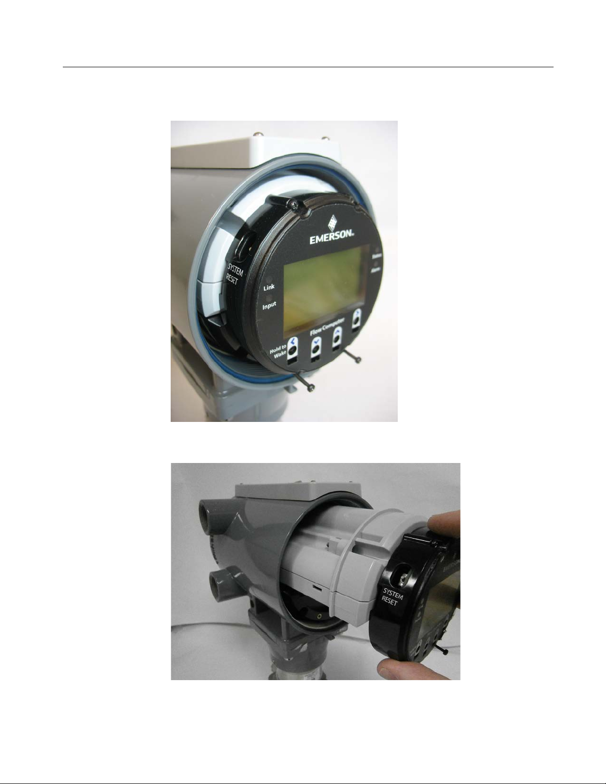
2. Grasp the end cap.
Front End Cap Rear End Cap
3
Page 10

FB1100/FB1200 Flow Computer Sensor Assembly Field Replacement Guide
D301842X012
November 2020
3. Unscrew the end cap turning it counter-clockwise until the cover comes off. Set it aside in
a safe location.
Note
If you need more leverage, place a long screwdriver or other appropriate tool across the
two notches in the end cap to act as a pry bar.
Front End Cap Removal Rear End Cap Removal
4. Disconnect power at terminal TB1 on the termination board.
5. Disconnect all terminal blocks and disconnect all wires (I/O, grounding, communications)
coming into the flow computer.
6. With a #2 Phillips-head screwdriver loosen the two recessed captive-fastening screws on
the battery pack enclosure.
4
Page 11
FB1100/FB1200 Flow Computer Sensor Assembly Field Replacement Guide
D301842X012
November 2020
7. With a #1 Phillips-head screwdriver, loosen the two bottom captive fastening screws on
the HMI module. Leave the two top screws on the HMI module connected to the battery
pack enclosure.
8. Grasp the HMI module and gently pull it and the battery pack enclosure out of the
housing.
9. If the battery pack enclosure holds an internal battery, disconnect the battery connector.
5
Page 12

FB1100/FB1200 Flow Computer Sensor Assembly Field Replacement Guide
D301842X012
November 2020
10. Set the battery pack enclosure/HMI module assembly aside. You will need it later.
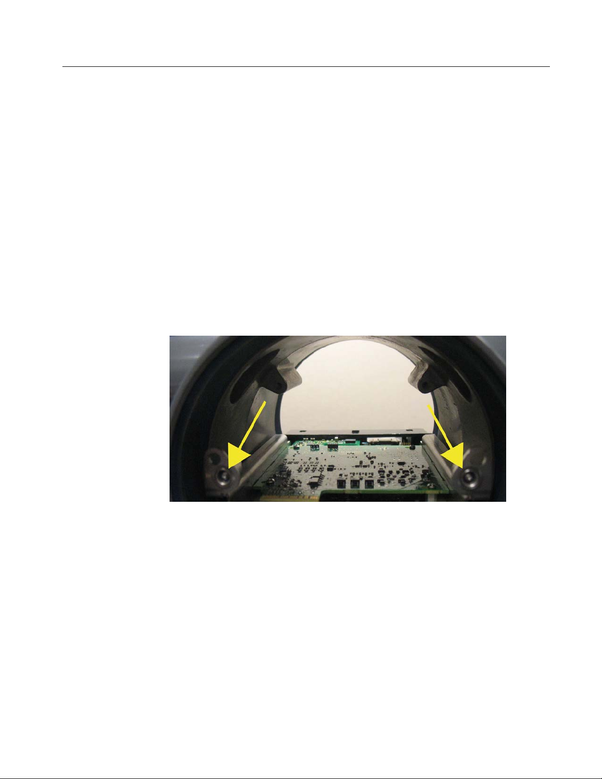
11. Look into the housing from the front. Two captive fastening screws on the inside of the
housing hold the termination board in place.
12. With a #2 Phillips-head screwdriver loosen the two captive fastening screws.
6
Page 13

FB1100/FB1200 Flow Computer Sensor Assembly Field Replacement Guide
D301842X012
November 2020
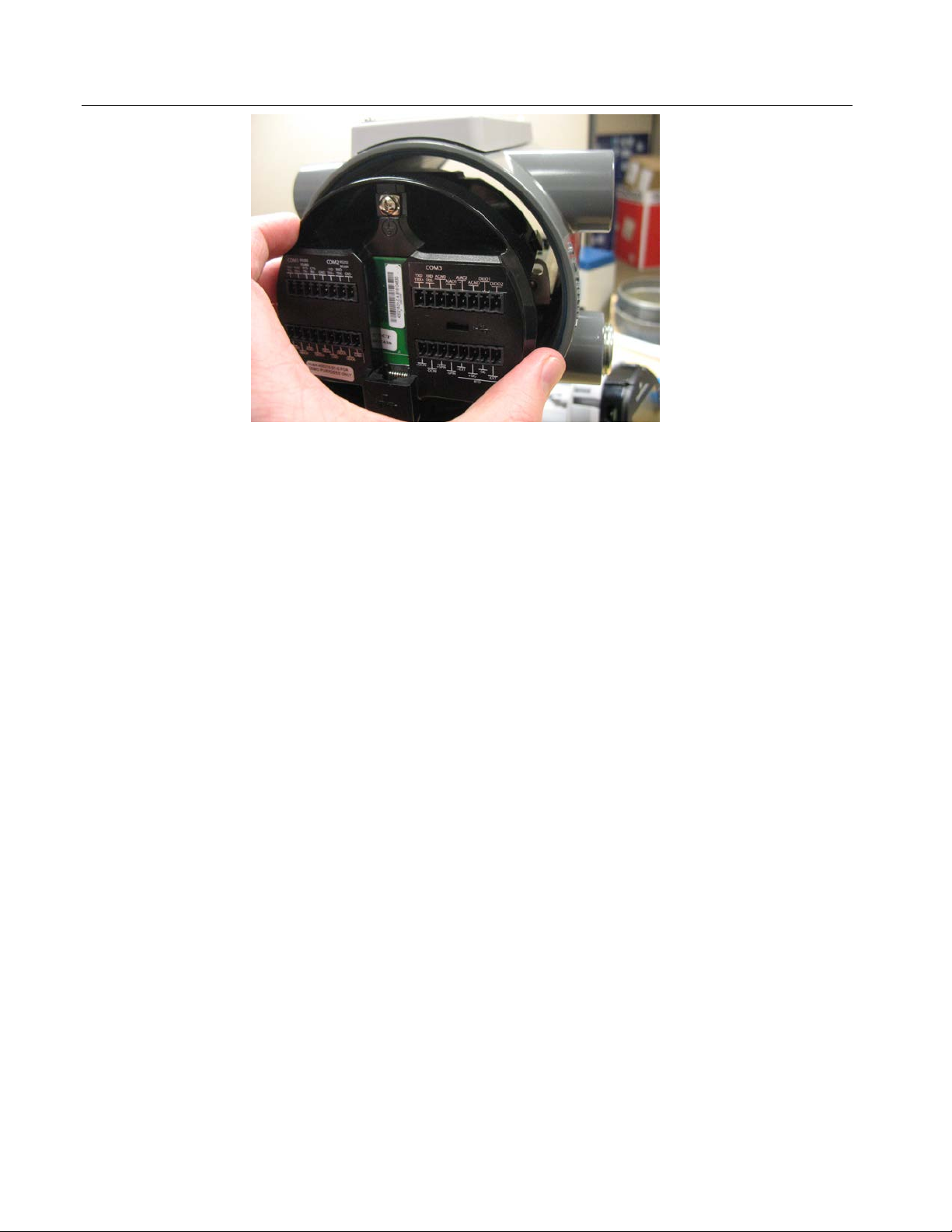
13. Now grasp the termination board bezel from the back of the unit and pull out the
termination board assembly.
14. With a #2 Phillips-head screwdriver, loosen the two captive fastening screws in the plastic
bezel that hold the CPU module in place. (To preserve data,
backup battery.)
do not remove the SRAM
7
Page 14

FB1100/FB1200 Flow Computer Sensor Assembly Field Replacement Guide
D301842X012
November 2020
15. Grasp the plastic bezel and gently pull the CPU module out of the housing.
16. Use a 3/32-inch flathead screwdriver to separate the internal wire connector plug from the
plug on the bottom of the CPU module.
17. Looking into the back end of the enclosure, use a #2 Phillips-head screwdriver to remove
the screws that hold the card cage to the enclosure.
8
Page 15
FB1100/FB1200 Flow Computer Sensor Assembly Field Replacement Guide
D301842X012
November 2020
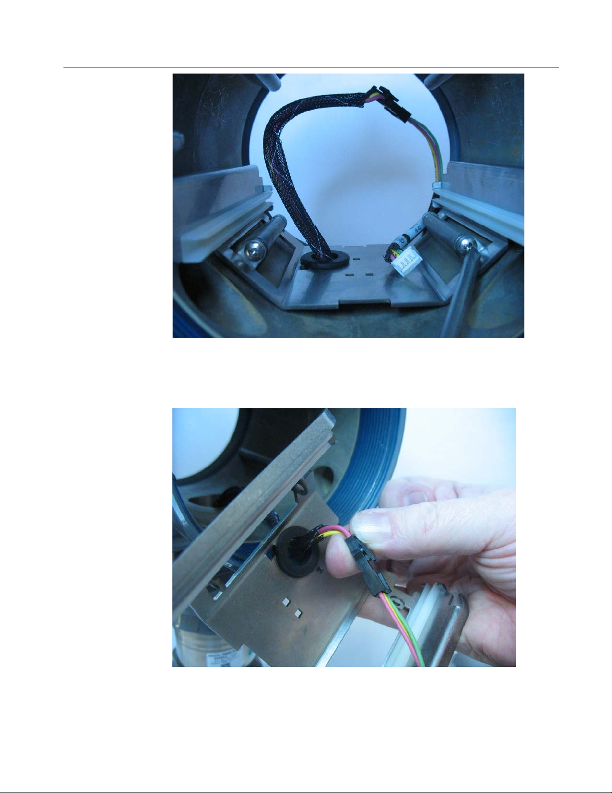
18. Looking into the front end of the enclosure, pull the card cage out of the enclosure, then
disconnect the upper part of the sensor cable and push the lower part through the
grommet so you can completely remove the card cage. Set the upper part of the sensor
cable aside; you will need it later.
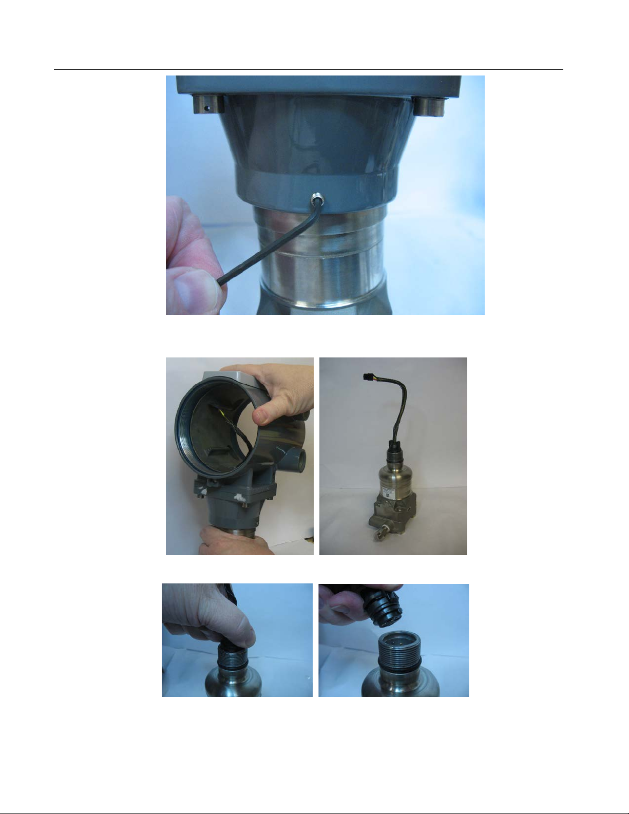
19. Use a 2 mm hex wrench to loosen the two rotation set screws on the side of the enclosure.
9
Page 16
FB1100/FB1200 Flow Computer Sensor Assembly Field Replacement Guide
D301842X012
November 2020
20. Grasp the sensor with one hand and unscrew the flow computer housing with your other
hand until you can lift it off. Then set the enclosure aside.
10
21. Grasp the sensor cable in detach it from the old sensor assembly.
22. Press the sensor cable onto the connector of the new (replacement) sensor assembly.
Page 17
FB1100/FB1200 Flow Computer Sensor Assembly Field Replacement Guide
D301842X012
November 2020
23. Lower the flow computer housing down onto the new sensor assembly making sure the
sensor cable fits through the hole in the bottom of the housing. Now rotate the housing
onto the sensor assembly until it is tight and positioned correctly for its installation site.
24. Tighten the rotation set screws. Torque screws to 4 to 6 in-lbs (0.5 to 0.7 N m).
25. Push the sensor cable through the grommet in the card cage.
26. Slide the card cage into its guides and line it up with the matching screw holes of the
enclosure, use a #2 Phillips-head screwdriver and screws to attach the card cage securely
to the enclosure. Torque screws to 8 to 12 in-lbs (0.9 to 1.4 N m).
27. Re-connect the lose section of the sensor cable to the bottom section of the sensor cable.
Snap the connector plug on the upper part of the sensor cable onto the mating plug on
the bottom of the CPU module and gently slide the new CPU module into the housing,
being careful not to pinch wires. Press firmly into place.
28. Use a #2 Phillips-head screwdriver to tighten the two captive fastening screws in the
plastic bezel that hold the CPU module in place. Torque screws to 4 to 6 in-lbs (0.5 to 0.7
N m).
29. Now look at the housing from back to front so you can see the captive fastening screws.
30. Take the termination board, align it with the captive fastening screw holes, and press it
into the back of the housing onto the captive fastening screws.
11
Page 18
FB1100/FB1200 Flow Computer Sensor Assembly Field Replacement Guide
D301842X012
November 2020
31. Tighten the screws that you loosened in step12. Torque screws to 4 to 6 in-lbs (0.5 to 0.7
N m).
32. Take the battery pack enclosure/HMI module assembly you removed in step 8. Being
careful to keep the battery wire and its connector free, carefully slide the assembly into
the front of the housing so that the HMI module mates with the green and yellow
connector from the CPU module. Tighten the screws you loosened in step 6 to hold the
assembly in place. Torque screws to 4 to 6 in-lbs (0.5 to 0.7 N m).
33. Tighten the bottom screws of the HMI module you loosened in step 7 with a torque of 4 to
6 in-lbs (0.5 to 0.7 N m).
34. You can now proceed to rewire all connections (I/O, communications, grounding) to the
flow computer. Please refer to the instruction manual for wiring installation instructions.
12
Page 19

FB1100/FB1200 Flow Computer Sensor Assembly Field Replacement Guide
D301842X012
November 2020
13
Page 20

FB1100/FB1200 Flow Computer Sensor Assembly Field Replacement Guide
For customer service and technical support,
Global Headquarters,
North America, and Latin America:
end-user.
Europe:
Middle East/Africa:
Asia-Pacific:
T +65 6777 8211| F +65 6777 0947
D301842X012
November 2020
visit www.Emerson.com/SupportNet
Emerson Automation Solutions
Remote Automation Solutions
6005 Rogerdale Road
Houston, TX 77072 U.S.A.
T +1 281 879 2699 | F +1 281 988 4445
www.Emerson.com/RemoteAutomation
Emerson Automation Solutions
Remote Automation Solutions
Unit 1, Waterfront Business Park
Dudley Road, Brierley Hill
Dudley DY5 1LX UK
T +44 1384 487200 | F +44 1384 487258
Emerson Automation Solutions
Remote Automation Solutions
Emerson FZE
P.O. Box 17033
Jebel Ali Free Zone – South 2
Dubai U.A.E.
T +971 4 8118100 | F +971 4 8865465
Emerson Automation Solutions
Remote Automation Solutions
1 Pandan Crescent
Singapore 128461
© 2018-2020 Remote Automation Solutions, a business unit of Emerson Automation
Solutions. All rights reserved.
This publication is for informational purposes only. While every effort has been made to ensure
accuracy, this publication shall not be read to include any warranty or guarantee, express or
implied, including as regards the products or services described or their use or applicability.
Remote Automation Solutions (RAS) reserves the right to modify or improve the designs or
specifications of its products at any time without notice. All sales are governed by RAS terms
and conditions which are available upon request. RAS accepts no responsibility for proper
selection, use or maintenance of any product, which remains solely with the purchaser and/or
Remote Automation Solutions
 Loading...