

Emerson FB3000 Remote Terminal Unit (RTU) Step-by-Step Separator Configuration Guide
Table of contents
 Loading...
Remote Automation Solutions Emerson FB3000 Remote Terminal Unit (RTU) Step-by-Step Separator Configuration Guide Manuals & Guides
Page 1
Emerson FB3000 Separator Configuration Guide
D301884X012
October 2019
Emerson FB3000 Remote Terminal Unit (RTU)
Step-by-Step Separator Configuration Guide
Contents i
Page 2

Emerson FB3000 Separator Configuration Guide
D301884X012
October 2019
Device Safety Considerations
Reading these Instructions
Before operating the device, read these instructions carefully and understand their safety implications.
In some situations, improperly using this device may result in damage or injury. Keep this manual in a
convenient location for future reference. Note that these instructions may not cover all details or
variations in equipment or cover every possible situation regarding installation, operation, or
maintenance. Should problems arise that are not covered sufficiently in the text, immediately contact
Customer Support for further information.
Protecting Operating Processes
A failure of this device – for whatever reason -- may leave an operating process without appropriate protection and
could result in possible damage to property or injury to persons. To protect against this, you should review the
need for additional backup equipment or provide alternate means of protection (such as alarm devices, output
limiting, fail-safe valves, relief valves, emergency shutoffs, emergency switches, etc.). Contact Remote
Automation Solutions for additional information.
Returning Equipment
If you need to return any equipment to Remote Automation Solutions, it is your responsibility to ensure that the
equipment has been cleaned to safe levels, as defined and/or determined by applicable federal, state and/or local
law regulations or codes. You also agree to indemnify Remote Automation Solutions and hold Remote Automation
Solutions harmless from any liability or damage which Remote Automation Solutions may incur or suffer due to
your failure to ensure device cleanliness.
Grounding Equipment
Ground metal enclosures and exposed metal parts of electrical instruments in accordance with OSHA rules and
regulations as specified in Design Safety Standards for Electrical Systems, 29 CFR, Part 1910, Subpart S, dated: April
16, 1981 (OSHA rulings are in agreement with the National Electrical Code). You must also ground mechanical or
pneumatic instruments that include electrically operated devices such as lights, switches, relays, alarms, or chart
drives.
Important: Complying with the codes and regulations of authorities having jurisdiction is essential to ensuring
personnel safety. The guidelines and recommendations in this manual are intended to meet or exceed applicable
codes and regulations. If differences occur between this manual and the codes and regulations of authorities
having jurisdiction, those codes and regulations must take precedence.
Protecting from Electrostatic Discharge (ESD)
This device contains sensitive electronic components which be damaged by exposure to an ESD voltage.
Depending on the magnitude and duration of the ESD, it can result in erratic operation or complete failure of the
equipment. Ensure that you correctly care for and handle ESD-sensitive components.
System Training
A well-trained workforce is critical to the success of your operation. Knowing how to correctly install, configure,
program, calibrate, and trouble-shoot your Emerson equipment provides your engineers and technicians with the skills
and confidence to optimize your investment. Remote Automation Solutions offers a variety of ways for your personnel
to acquire essential system expertise. Our full-time professional instructors can conduct classroom training at several of
our corporate offices, at your site, or even at your regional Emerson office. You can also receive the same quality
training via our live, interactive Emerson Virtual Classroom and save on travel costs. For our complete schedule and
further information, contact the Remote Automation Solutions Training Department at 800-338-8158 or email us at
education@emerson.com
.
Contents ii
Page 3

Emerson FB3000 Separator Configuration Guide
D301884X012
October 2019
Contents
Chapter 1. Introduction 1
1.1 FB3000 RTU ............................................................................................................................................ 1
1.1.1 Solutions ...................................................................................................................................... 2
1.1.2 Applications ................................................................................................................................. 2
1.2 Demo Overview ...................................................................................................................................... 2
1.2.1 Demo Folders .............................................................................................................................. 2
1.2.2 I/O Points ..................................................................................................................................... 3
1.3 Field Tools ............................................................................................................................................... 3
1.3.1 FBxConnect.................................................................................................................................. 3
1.3.2 FBxDesigner ................................................................................................................................. 4
Chapter 2. Field Tools & Connecting to RTU 5
2.1 Starting Field Tools .................................................................................................................................. 5
2.2 Field Tools Overview ................................................................................................................................ 7
2.3 Connecting to the RTU ............................................................................................................................ 8
Chapter 3. FBxConnect 11
3.1 FBxConnect Overview............................................................................................................................ 11
3.2 Guided Setup ........................................................................................................................................ 12
3.2.1 IO Setup & Communications ...................................................................................................... 14
3.2.2 History & Summary .................................................................................................................... 29
3.3 Math Blocks ........................................................................................................................................... 30
3.3.1 Simulating Liquid Level .............................................................................................................. 31
3.3.2 Simulating Pressure ................................................................................................................... 35
3.4 Action Blocks & Effects .......................................................................................................................... 38
3.4.1 Simulating the High Level Switch ............................................................................................... 39
3.4.2 Simulating the Low Level Switch ................................................................................................ 40
3.5 PID Loops .............................................................................................................................................. 43
3.5.1 Controlling the Pressure ............................................................................................................. 44
Chapter 4. FBxDesigner 47
4.1 FBxDesigner Overview ........................................................................................................................... 47
4.2 Creating a Project .................................................................................................................................. 49
4.2.1 Creating an FBD Program ........................................................................................................... 51
4.2.2 Creating an FBD Block with ST .................................................................................................... 60
4.2.3 Tasks, Compiling & BootProject ................................................................................................. 65
Chapter 5. FBxVue 69
5.1 FBxVue Overview ................................................................................................................................... 69
5.2 Building a Display with FBxVue .............................................................................................................. 72
Chapter 6. Applications 91
Contents iii
Page 4

Emerson FB3000 Separator Configuration Guide
D301884X012
October 2019
Contents iv
Page 5
Emerson FB3000 Separator Configuration Guide
Release 1 - Core Equipment
Chapter 1. Introduction
This demo guide is an introductory exercise to familiarize you with the capabilities of the
FB3000 Remote Terminal Unit (RTU) and is organized into the following chapters:
Chapter 1: Introduction:
Provides an overview of theFB3000 RTU, this demo, and the required software.
Chapter2: Field Tools & Connecting to the RTU:
Details how to connect to the FB3000 using Field Tools.
Chapter 3: FBxConnect:
Describes how to set up meters and controls using the FBxConnect software.
Chapter 4: FBxDesigner:
Details how to create a control program using the FBxDesigner programming
environment.
Chapter 5: FBxVue
Details how to create user displays using the FBxVue display builder.
Chapter 6: Applications
Describes how to download and distribute the project and display as one packaged
application.
D301884X012
October 2019
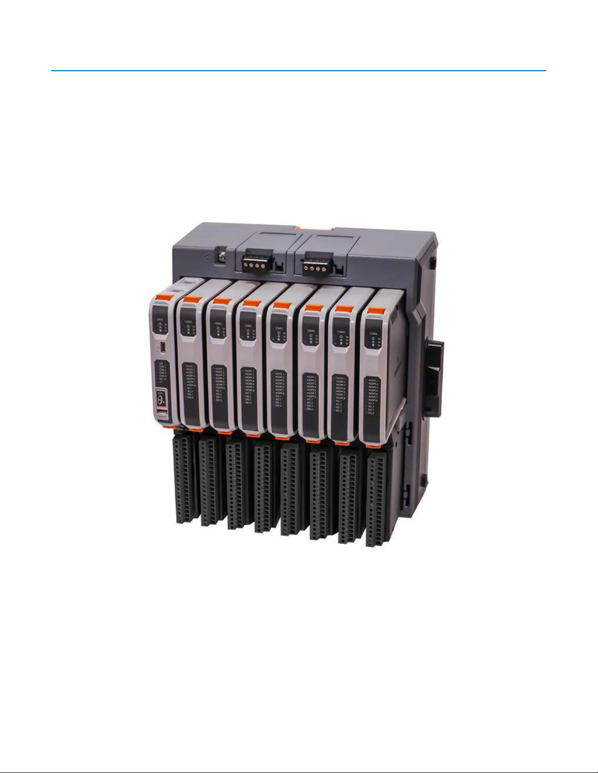
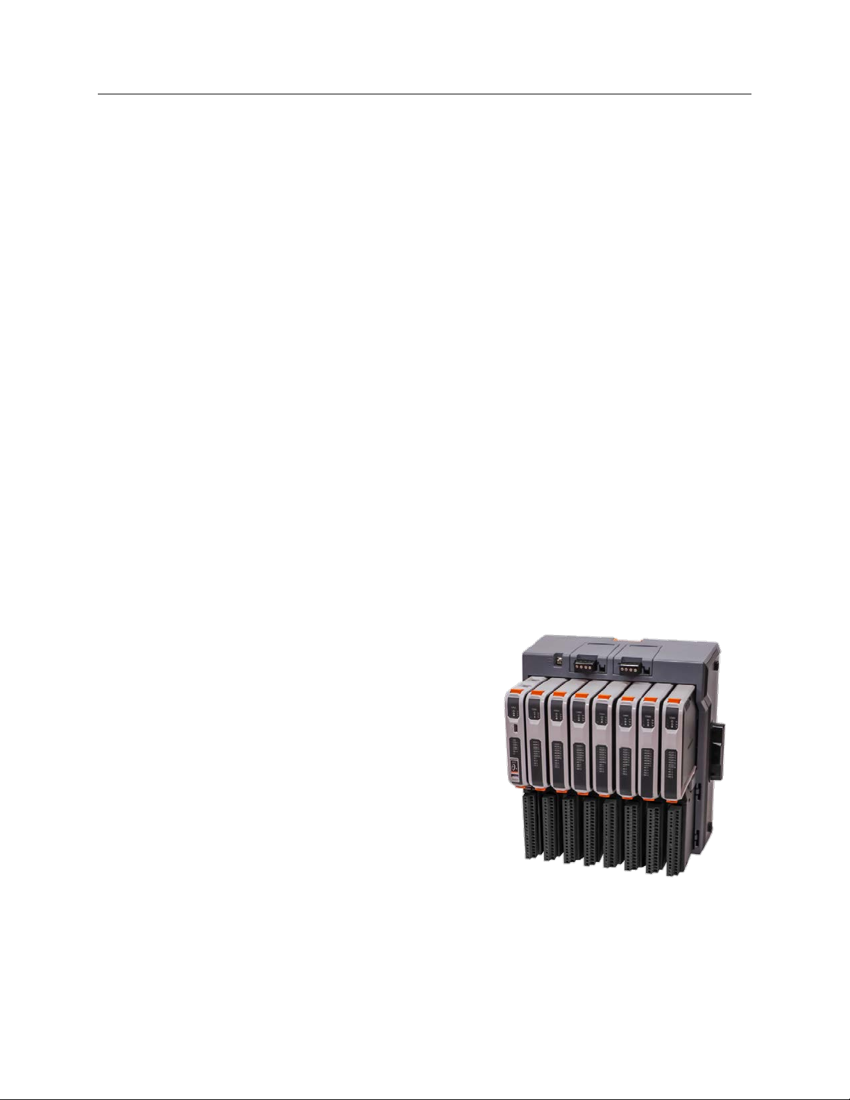
1.1 FB3000 RTU
The Emerson FB3000 Remote Terminal Unit (RTU) runs measurement and control
applications suitable for oil and gas, water, wastewater, and other industrial processes. It
combines the ease-of-configuration of the Emerson ROC/FloBoss RTUs and the flexible
programmability of the Emerson ControlWave PLCs.
• 8 slot Chassis (CSA, ATEX, IEC Ex)
• 10.5-30Vdc Dual Power Supply
Cartridges
• 4 Serial + 1 USB Comm ports
• 2 independent Ethernet ports
• 32-bit Processor running at 792 MHz
• 256 MB flash storage for firmware &
reports
• 16 MB SRAM storage for historical data
• 1 GB DRAM execution memory
• Mixed I/O Card (8AI/DI/PI + 2AO + 2DO)
• Isolated Personality Modules (Terminal
Blocks)
• Hot-Swappable I/O
• Connectivity to 10 MVS per Comm port
Introduction 1
Page 6

Emerson FB3000 Separator Configuration Guide
D301884X012
October 2019
1.1.1 Solutions
The configuration, control and communication data in the RTU are saved in a hierarchy of
folders called a solution (with a file type of .zsl). A solution may also include up to eight
applications. You use FBxConnect to modify, upload, or download solutions.
Note
It is a good practice to always save backups of your solutions.
1.1.2 Applications
Applications add extra functionality to the FB3000. An application consists of a project
created in FBxDesigner and can include multiple displays built with FBxVue. Each
application runs in its own task and can be independently added, removed, started, or
stopped.
1.2 Demo Overview
In this demo you use an FB3000 to simulate and control a two-phase separator, including
the measurement of the outlet gas and liquid streams.
The gas is measured with a DP meter using API 21.1-compliant AGA 3 flow calculations
while the liquid is measured with a linear turbine meter. The liquid level of the separator is
measured by a guided wave radar device and monitored by high- and low-level switches. A
control valve on top of the separator regulates the gas flow to control pressure and a
control valve on the bottom of the separator regulates the liquid to control the liquid level.
During normal operation, a PID controls the gas control valve to maintain the pressure at a
setpoint. The liquid level control valve opens when the high-level switch activates and
closes when the low-level switch activates.
You use FBxConnect to build the FB3000’s standard configuration, which includes IO
configuration, meter set-up, and controls for the simulation of the separator;
to build a program that opens and closes the liquid control valve; and FBxVue to build a
user display that includes a graphic of the separator liquid level, a gauge for the pressure,
and the status of the control valves and meters.
1.2.1 Demo Folders
This demo contains the following folders:
Application:
Contains the Level_Control.zap file which is the packaged application created in this
demo, containing the FBxDesigner project and the FBxVue display.
Display:
Contains the Separator Display.xml file which is the FBxVue display created in this
demo, and an images folder with the Sep_icon_2.png image used in the display.
Documentation:
Contains this document, as well as a slideshow and video version.
FBxDesigner
2 Introduction
Page 7
FBxDesigner Project:
I/O Type
Purpose
Signal Type
AI
DI
DI
AI
AI
PI
Digital
DO
AO
Contains the Level_Control.mwt project file along with its accompanying project
folder/source code.
Solution:
Contains the Separator_Demo.zsl solution file and its accompanying folder. This is the
solution created in this demo, which includes a copy of the application.
Note
This document is a complete guide to the demo; any other documents cited are
references.
1.2.2 I/O Points
The following table shows the I/O points to be used. You set up the inputs in override
mode and simulate them using the FB3000 control features.
Emerson FB3000 Separator Configuration Guide
D301884X012
October 2019
Liquid Level 4—20 mA
Hi-level Switch 24 Vdc input
Note
This demo shows the I/O configuration using one 12-channel Mixed IO module (with 8
selectable AI/DI/PI inputs and 2 AO and 2 DO settings). Other types of I/O modules may be
used but are not show in this guide.
1.3 Field Tools
The Field Tools software suite establishes communications with the FB3000, stores
connection information, and contains several applications (primarily FBxConnect and
FBxDesigner).
Lo-level Switch 24 Vdc input
Pressure Setpoint 4—20 mA
Pressure 4—20 mA
Liquid Meter 24 Vdc input
MVS Gas Meter Dat RS-285 Serial
Liquid Level Control Valve 24 Vdc output
Gas Pressure Control Valve 4—20 mA
1.3.1 FBxConnect
FBxConnect automatically opens when you connect to an RTU. Use to create and modify
solutions, download data, and other common tasks for the RTU. FBxConnect includes
configurable control features such as PID Loops, Math Blocks, and Action & Effects. It also
includes an integrated display builder, FBxVue, you use to create customized graphical
displays that can be combined with FBxDesigner projects into applications.
Introduction 3
Page 8

Emerson FB3000 Separator Configuration Guide
D301884X012
October 2019
1.3.2 FBxDesigner
Note
FBxDesigner is a separate program in Field Tools that must be licensed to a PC.
Use FBxDesigner to program functions beyond what is offered in FBxConnect. FBxDesigner
supports the five IEC61131 programming languages by incorporating the industrystandard MULTIPROG IEC 61131 programming tool and includes a library of predefined
function blocks tailored specifically for referencing data in the FB3000 RTU.
4 Introduction
Page 9
Emerson FB3000 Separator Configuration Guide
D301884X012
October 2019
Chapter 2. Field Tools & Connecting to RTU
Note
For this chapter, you must have already successfuly installed Field Tools and previously
licensed FBxDesigner.
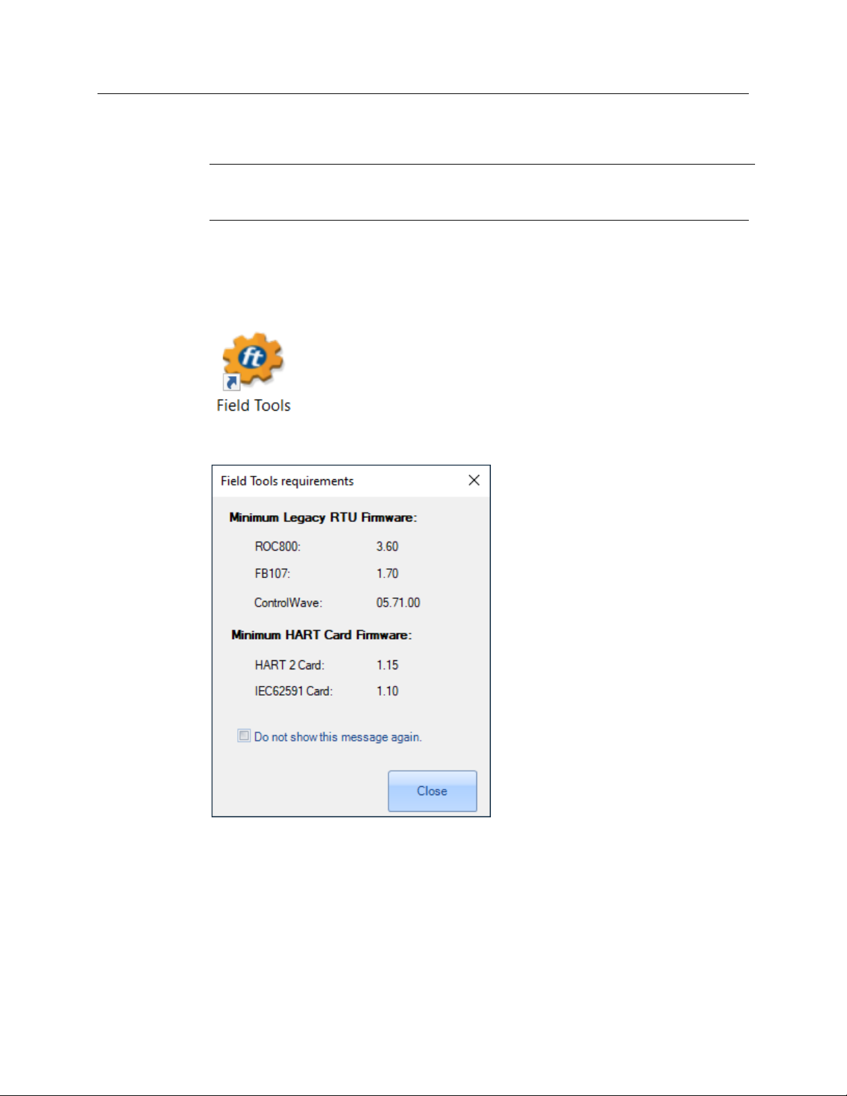
2.1 Starting Field Tools
Click on the Field Tools desktop icon to start Field Tools.
If the Field Tools requirements window pops up, click Close.
If this is the first-time you have opened Field Tools, the default username is admin with no
password.
Field Tools & Connecting to the RTU 5
Page 10

Emerson FB3000 Separator Configuration Guide
D301884X012
October 2019
Click Log in.
Click OK. The system requires that you change the password for the admin account.
To connect to a new FB3000, enter the default password of admin and click OK. Field Tools
starts.
6 Field Tools & Connecting to the RTU
Page 11

Emerson FB3000 Separator Configuration Guide
2.2 Field Tools Overview
Field Tools features a Connections List on the left-hand side of the screen, where you can
save multiple connections, sorted by site. You can open multiple connections at once, and
each selected connection opens a new instance of FBxConnect.
D301884X012
October 2019
Field Tools has the following selections in the top menu:
Connections:
Add Connections, Direct Connect, Import/Export Connections Lists.
Configurations/Solutions:
Create new or open existing solutions with FBxConnect.
Security:
Manage user accounts and passwords.
Settings:
Edit system settings
Help:
Access the online help system and view the version of Field Tools.
Field Tools & Connecting to the RTU 7
Page 12

Emerson FB3000 Separator Configuration Guide
D301884X012
October 2019
2.3 Connecting to the RTU
To establish a connection with the FB3000 RTU, first ensure that the RTU is powered on
and connected to your computer using one of the comm ports (Ethernet, USB, or serial).
In Field Tools, click Connections > Add connection.
The Local connection to FBx device window displays; use it to create the new connection.
Enter a name for the connection. This will be the name in the Field Tools Connections List.
Select a Connection Type.
If you are connecting through IP with an ethernet cable, enter the default IP address of
the ethernet port you are connecting to (either
192.168.2.10 for port 2):
8 Field Tools & Connecting to the RTU
192.168.1.10 for port 1 or
Page 13

Emerson FB3000 Separator Configuration Guide
D301884X012
October 2019
Note
You may need to change your PC’s ethernet port adapter settings to have a similar IP
address and subnet mask.
If you are connecting through Serial/USB, select the Comm port you are using.
After selecting your connection type, click Connect.
The system then shows the progress of the connection in the lower part of the Connection
parameters pane:
Once a connection establishes, an instance of FBxConnect automatically opens
(FBxConnect may take a few moments to load). When FBxConnect opens, it shows an
image of the FB3000:
Field Tools & Connecting to the RTU 9
Page 14

Emerson FB3000 Separator Configuration Guide
D301884X012
October 2019
The status bar on the bottom of the screen shows that you are online, logged in as admin,
and indicates the IP address in use.
10 Field Tools & Connecting to the RTU
Page 15

Emerson FB3000 Separator Configuration Guide
Chapter 3. FBxConnect
Use FBxConnect to create or modify a solution, which consists of the standard
configuration along with communication parameters and applications. In this section we
will create the Standard Configuration for the demo.
3.1 FBxConnect Overview
FBxConnect features a ribbon menu on the top of the screen:
The ribbon menu has the following tabs:
D301884X012
October 2019
File:
Upload/Download Solutions, save backup to Flash.
Monitor:
View the status of I/O, system parameters, meters, logs, comm ports, etc.
Configure:
Make changes to the Solution such as setting up Meters, IO, History, and control
functions.
Services:
Upgrade firmware, warm/cold start the RTU, Calibrate I/O, manage User Security
profiles, and add licenses.
Reports:
Download History, Configuration, and Miscellaneous reports.
Applications:
Manage and view Applications.
FBxVue:
Build and view user displays.
Help:
Access the online Help system.
Note
For security purposes, you should change the default admin password (using the Services
tab) on the RTU after your initial login.
FBxConnect 11
Page 16
Emerson FB3000 Separator Configuration Guide
D301884X012
October 2019
3.2 Guided Setup
The Guided Setup Wizard walks you through the screens needed to set up IO points, set
up meters, and configure history for those meters. Each of these actions can also be found
through other means.
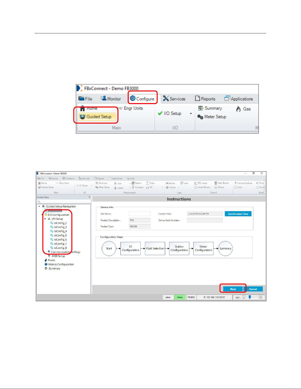
To start the wizard, select the Configure tab and then click Guided Setup.
There are two ways to navigate the Guided Setup:
Click Next or Apply on the bottom right to go to the next page.
Click on a page in the Navigation Pane on the left to directly go to it (this option can
skip important configuration steps, so it is
not recommended).
The Instructions page shows the steps in the configuration process and also allows you to
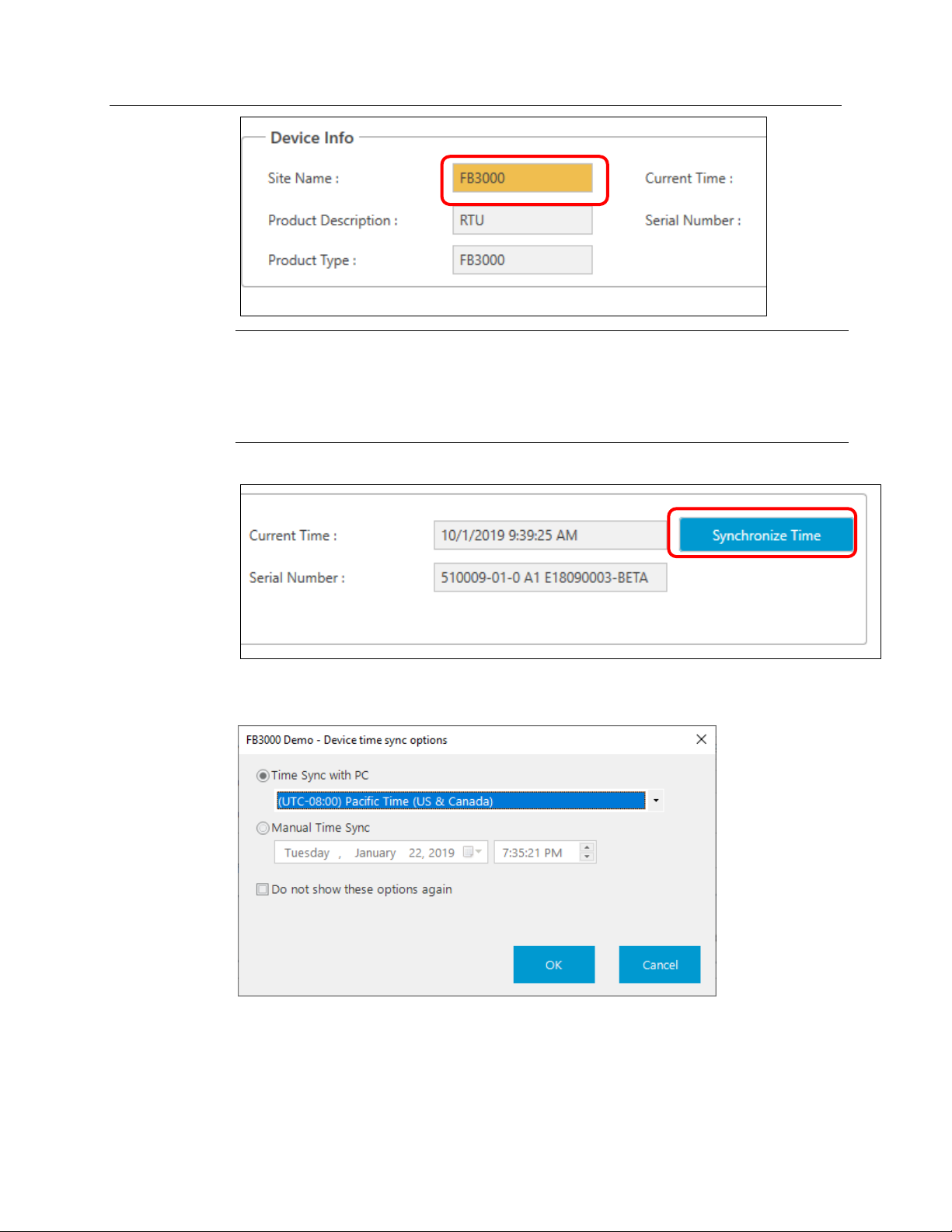
set the Device Info. Enter a Site Name.
12 FBxConnect
Page 17
Emerson FB3000 Separator Configuration Guide
D301884X012
October 2019
Note
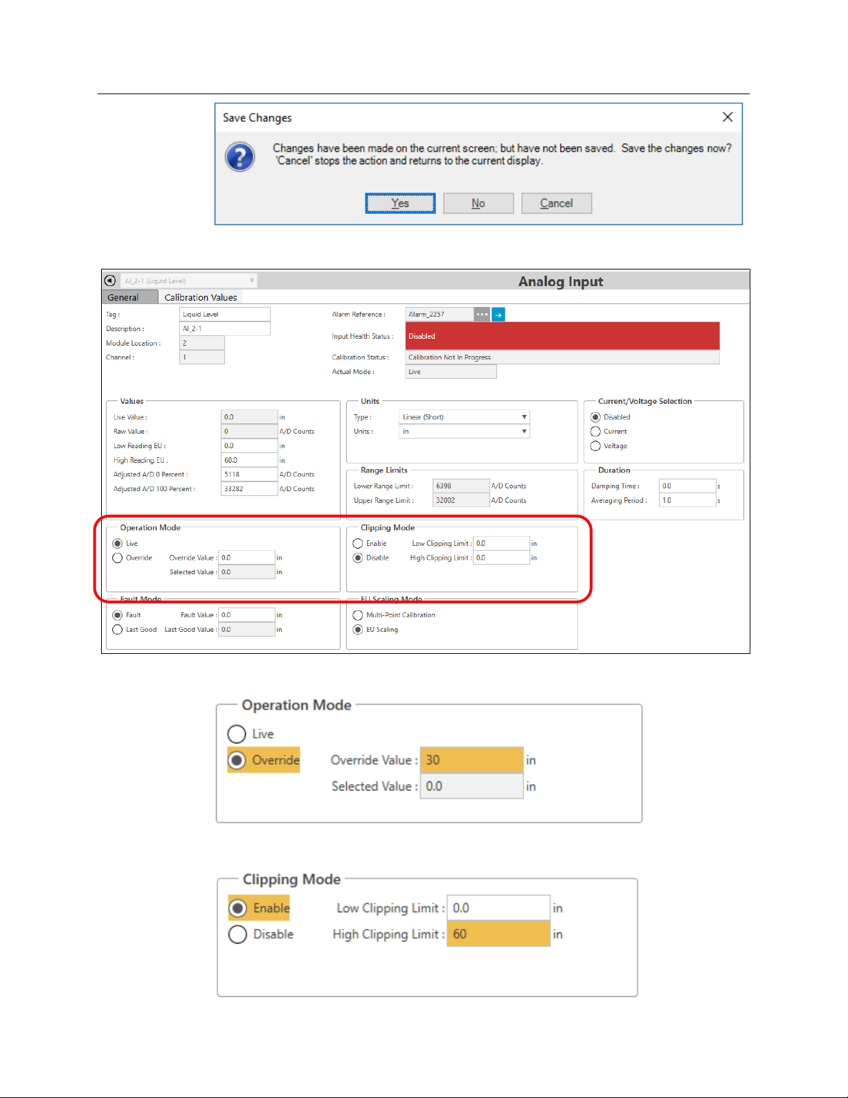
As show above, the system always highlights unsaved changes using yellow or amber.
Clicking
leave a screen without saving, the system displays a verification prompt reminding you to
save or discard the changes.
Click Synchronize Time.
Apply, Save, or Next saves the settings or changes on the current screen. If you
You can either synchronize the date and time with your PC’s clock (you can select a
different time zone) or manually set a date and time.
Click OK, and then click Next.
FBxConnect 13
Page 18
Emerson FB3000 Separator Configuration Guide
Inputs
Tag
Unit Type
Unit
Type
EU Scaling
Mode
Low
High
1
2
D301884X012
October 2019
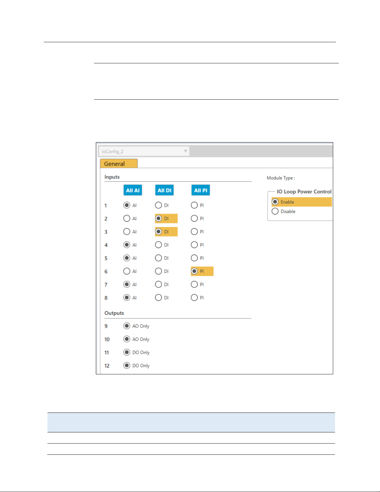
3.2.1 IO Setup & Communications
Note
This section assumes you have installed a 12-channel Mixed IO module in slot 2 for all the
needed I/O. (The 12-channel Mixed IO module has 8 selectable AI/DI/PI inputs and 2 AO and
2 DO settings.)
The next few screens enable you to configure I/O on the RTU.
Select the Input types as shown below.
Enable Loop Power.
Click Apply.
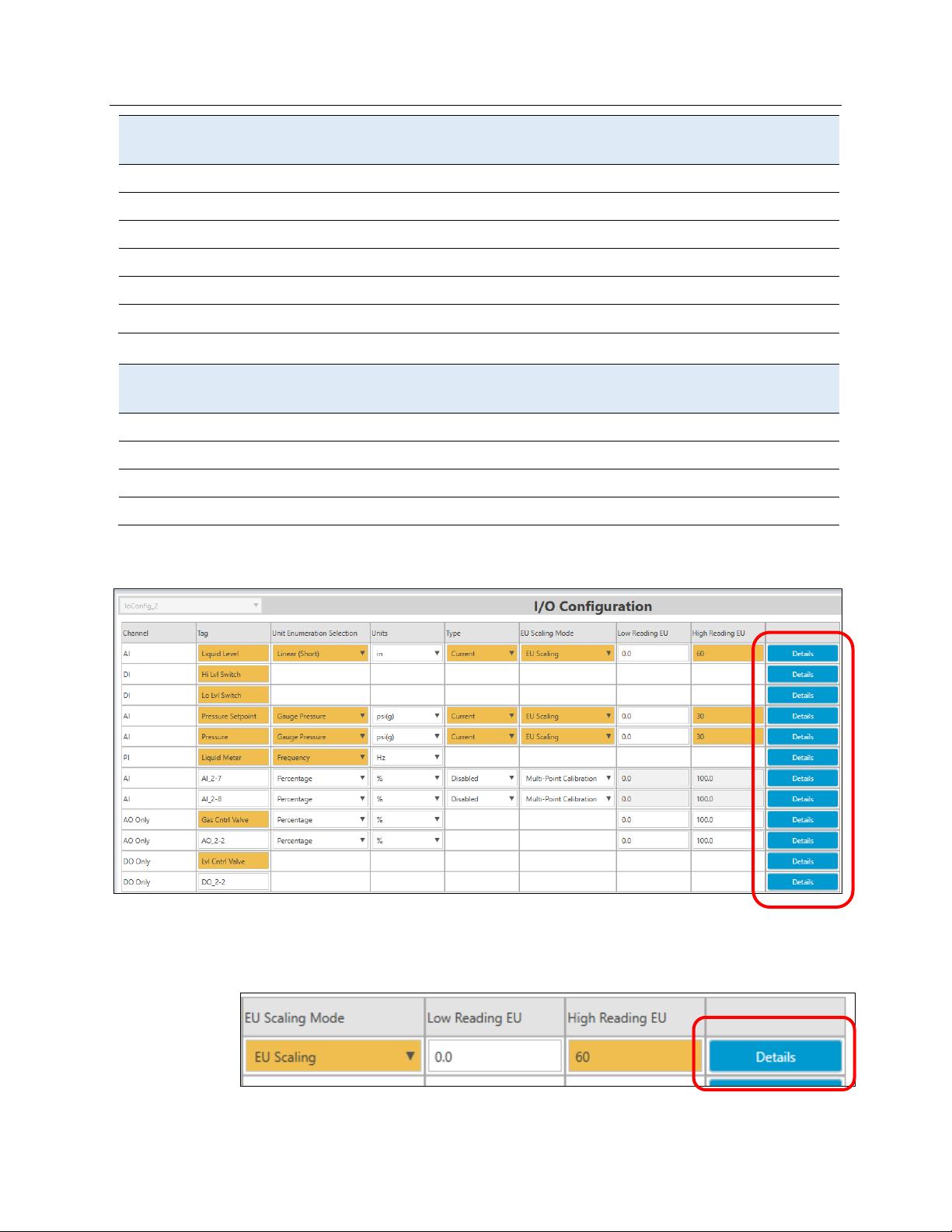
On the next IO Setup screen, you can tag and define each I/O point in the module.
Complete the IO Setup screen according to the following table:
AI Liquid Leve Linear (Short) In Current EU Scaling 0 60
DI Hi Lvl Switch
14 FBxConnect
Page 19
Emerson FB3000 Separator Configuration Guide
Inputs
Tag
Unit Type
Unit
Type
EU Scaling
Mode
Low
High
3
4
5
6
7
8
Outputs
Tag
Unit Type
Unit
Type
EU Scaling
Mode
Low
High
9
10
11
12
D301884X012
October 2019
DI Lo Lvl Switch
AI Pressure Setpoint Gauge Pressure psi(g) Current EU Scaling 0 30
AI Pressure Gauge Pressure psi(g) Current EU Scaling 0 30
PI Liquid Meter Frequency Hz Current
AI
AI
AO Gas Cntrl Valve Percentage % 0 100
AO
DO Lvl Cntrl Valve
DO
When you are done the screen should look like this:
On this screen you can also click Details for each I/O point to individually configure its
behavior. To simulate the separator later, we need to set all the inputs to Override mode.
Click Details for
The system prompts you to save the changes on the current screen. Click Yes to continue.
FBxConnect 15
Liquid Level (AI_2-1)
:
Page 20
Emerson FB3000 Separator Configuration Guide
D301884X012
October 2019
The system displays a Configuration screen for the selected input:
Select the Override option in the Operation Mode pane and enter an Override Value of 30:
Select the Enable option in the Clipping Mode pane and enter a High Clipping Limit of 60:
16 FBxConnect
Page 21
Emerson FB3000 Separator Configuration Guide
D301884X012
October 2019
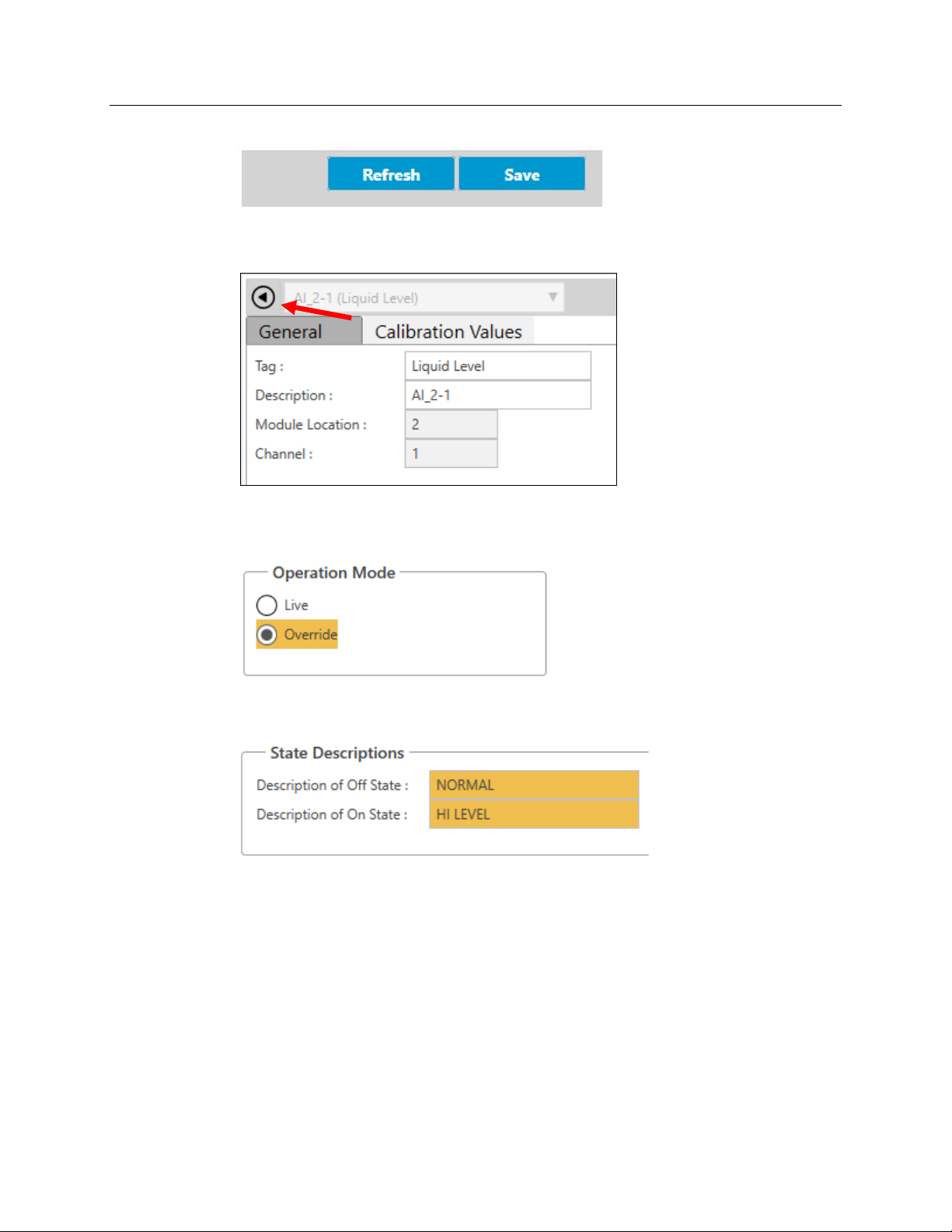
Click Save on the screen’s bottom right corner.
Click the back arrow at the top left corner of the screen to redisplay the IO Configuration
screen.
Click Details for
Select the Override option in the Operation Mode pane.
In the State Descriptions pane, enter NORMAL as the Description of Off State and HI LEVEL
as the Description of On State.
Click Save and click the back arrow to redisplay the IO Configuration screen.
Click Details for
Select the Override option in the Operation Mode pane.
Enter NORMAL as the Description of Off State and LOW LEVEL as the Description of On
State.
Hi Lvl Switch (DI_2-2)
Lo Lvl Switch (DI_2-3)
and make the following edits:
and make the following edits:
Click Save and click the back arrow to redisplay the IO Configuration screen.
Click Details for
Select the Override option in the Operation Mode pane and set an Override Value of
10.
Select the Enable option in the Clipping Mode pane and enter a High Clipping Limit of
30.
FBxConnect 17
Pressure Setpoint (AI_2-4)
and make the following edits:
Page 22
Emerson FB3000 Separator Configuration Guide
D301884X012
October 2019
Click Save and click the back arrow to redisplay the IO Configuration screen.
Click Details for
Select the Override option in the Operation Mode pane and set an Override Value of
10.
Select the Enable option in the Clipping Mode pane and enter a High Clipping Limit of
30.
Click Save and click the back arrow to redisplay the IO Configuration screen.
Click Details for Liquid Meter (PI_2-6) and make the following edits:
Select the Override option in the Operation Mode pane and set an Override Frequency
of
100.
Click Save and click the back arrow to redisplay the IO Configuration screen.
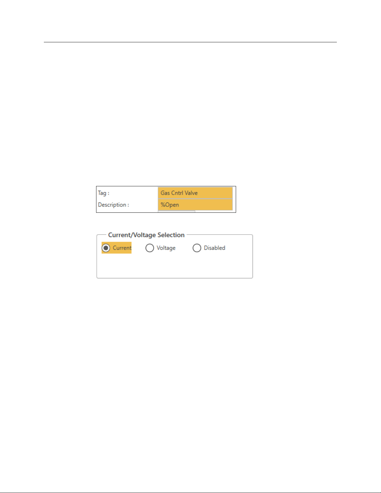
Click Details for
Enter %Open as the description.
In the Current/Voltage Selection pane, select the Current option:
Pressure (AI_2-5)
and make the following edits: :
Gas Cntrl Valve (AO_2-1)
and make the following edits:
Click Save and click the back arrow to redisplay the IO Configuration screen.
Click Details for
Enter OPEN/CLOSE as the Description.
Enter OPEN as the Description of On State and CLOSED as the Description of Off State.
In the Operation Mode pane, select the Auto Value to On.
Click Save and click the back arrow to redisplay the IO Configuration screen.
When the IO Configuration screen redisplays, if you were to click Apply, the wizard takes
you to the IO Configuration page for the next module (located in slot 3). Since we are
using the rest of the IO modules for this demo, we want to
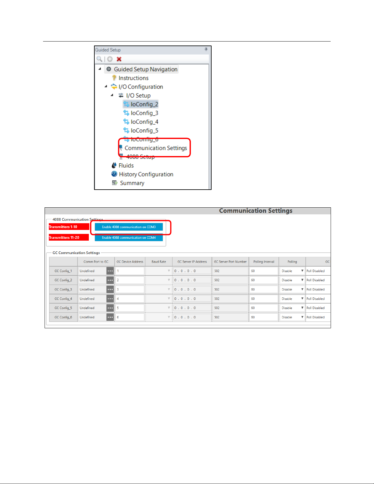
Instead, double-click Communication Settings in the Navigation pane on the left-hand side
of the screen to skip to that page.
Lvl Cntrl Valve (DO_2-1)
and make the following edits:
not
skip this step.
18 FBxConnect
Page 23
Emerson FB3000 Separator Configuration Guide
The Communications Settings screen displays.
D301884X012
October 2019
At this point, you set up communications with 4088 MVS transmitters and gas
chromatographs (GCs). Click
This sets the RTU’s COM3 to accept 4088 MVS communications. You can define up to 10
4088s (labeled 1—10; COM4 supports another 10 devices, labeled 11—20).
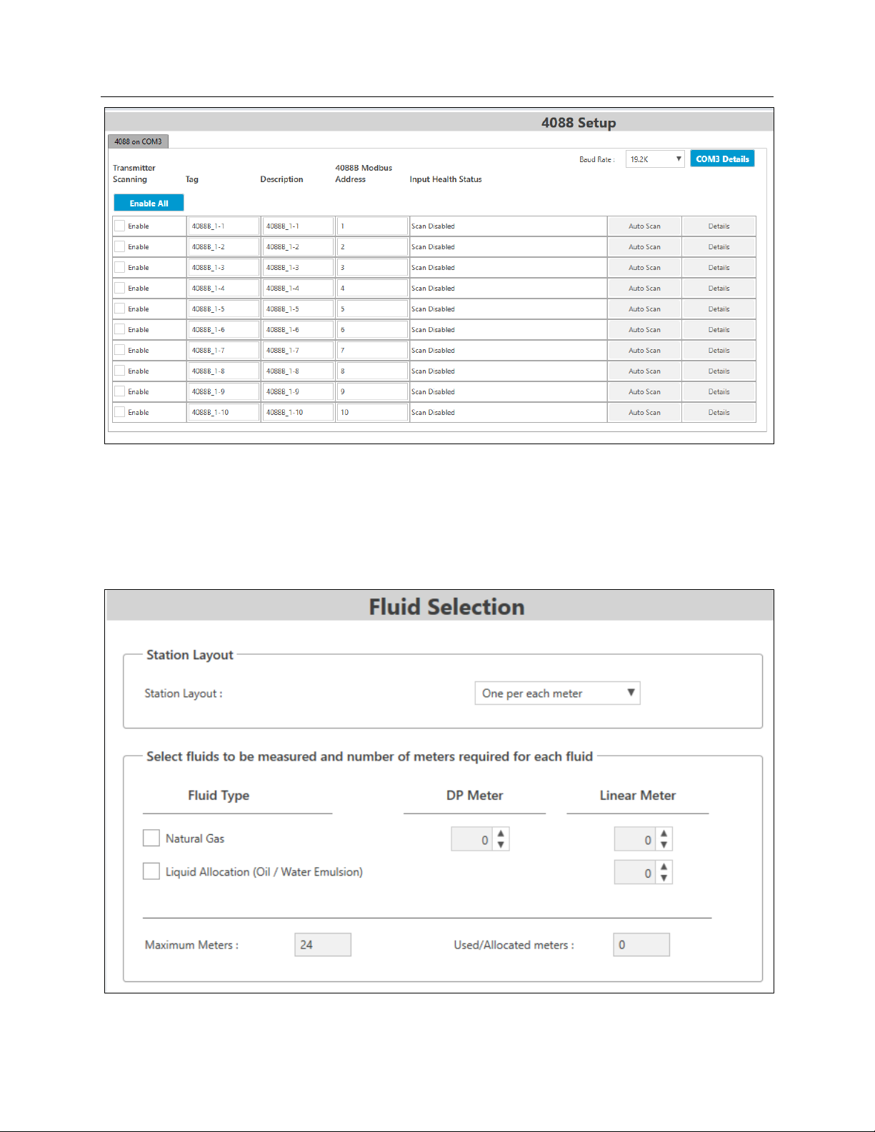
Click Apply. The 4088 Setup screen displays, which you use to configure communications
with any connected 4088 transmitters.
FBxConnect 19
Enable 4088 communication on COM3.
Page 24
Emerson FB3000 Separator Configuration Guide
D301884X012
October 2019
Since we are not enabling any 4088s for this demo, click Apply to continue. The Fluid
Selection screen displays
3.2.2 Stations & Meters
Using the Fluid Selection screen, you select the fluids to be measured and the type and
quantity of meters. You can also configure stations.
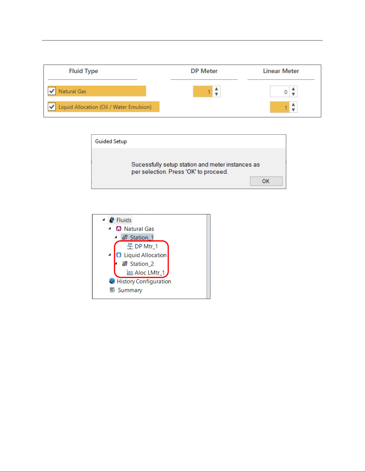
In the Select fluids pane, select the Natural Gas option and add one DP Meter to measure
it.
20 FBxConnect
Page 25
Emerson FB3000 Separator Configuration Guide
D301884X012
October 2019
Under Fluid Type, select the Liquid Allocation option and add one Linear Meter to measure
it.
Click Apply. The wizard displays a verification dialog:
Click OK. Notice that the stations and meter you have added now appear in the navigation
pane:
The wizard displays the Engineering Units screen. Each station has its own set of reporting
units, which you configure on this screen.
FBxConnect 21
Page 26

Emerson FB3000 Separator Configuration Guide
D301884X012
October 2019
Using the buttons at the top of the screen, set all units to your preferred regional type and
click
Apply. The wizard displays the Station screen.
Use this screen to set station parameters such as contract hour, base conditions,
calculation methods, and gas components. Select the options for your organization’s
requirements and click
If you left the Operation Mode on Override (its default value) in the Station screen’s
Component Configuration pane, the wizard displays the Gas Composition screen.
Next.
22 FBxConnect
Page 27

Emerson FB3000 Separator Configuration Guide
D301884X012
October 2019
Enter the appropriate values for the gas component compositions and select a
Normalization Option. Then click
Next. The wizard displays the DP Meter Settings screen.
Use this screen to configuration the options for the gas DP meter and select its inputs.
Select whatever options you prefer in the General section. In the Meter Inputs section,
Click the Point Picker button [
The Point Picker screen opens; use it to select an OPI (a point in the FB3000’s database) to
use for the differential pressure.
FBxConnect 23
...]next to the Differential Pressure option to select a point.
Page 28

Emerson FB3000 Separator Configuration Guide
D301884X012
October 2019
Note the filter on the top of the Point Picker showing Differential Pressure. That filter limits
the listed objects and instances to only three objects rather than displaying the entire
database.
Select DP_ in Objects and instances and then Select 4088B-1 DP (Instance 1-1). This is the
Differential Pressure measurement from the first 4088 MVS instance on COM3.
Note
We enabled COM3 for 4088s earlier so that we could select them here as meter inputs.
Click OK. DP_1-1 is now shown as the DP input.
24 FBxConnect
Page 29

Emerson FB3000 Separator Configuration Guide
Select Override Mode and enter a value of 25.
Define the Static Pressure:
Open the Flowing Pressure Point Picker.
Select Pres_ and then the first 4088 instance again.
Select Override Mode and enter a value of 25.
Define the Temperature:
Open the Flowing Temperature Point Picker.
Select RTD and then the first 4088 instance.
Select Override Mode and enter a value of 75.
D301884X012
October 2019
Click Next. The wizard displays the Engineering Units for station 2 (for the Liquid Allocation
Meter):
FBxConnect 25
Page 30

Emerson FB3000 Separator Configuration Guide
D301884X012
October 2019
In the Rates pane, select bbl/d as the Volume Units for Rates:
Click Apply to continue. The wizard displays the Stations screen. Note that the station
settings for the Liquid Allocation station do not have the same Calculation and
Composition options.
26 FBxConnect
Page 31

Emerson FB3000 Separator Configuration Guide
D301884X012
October 2019
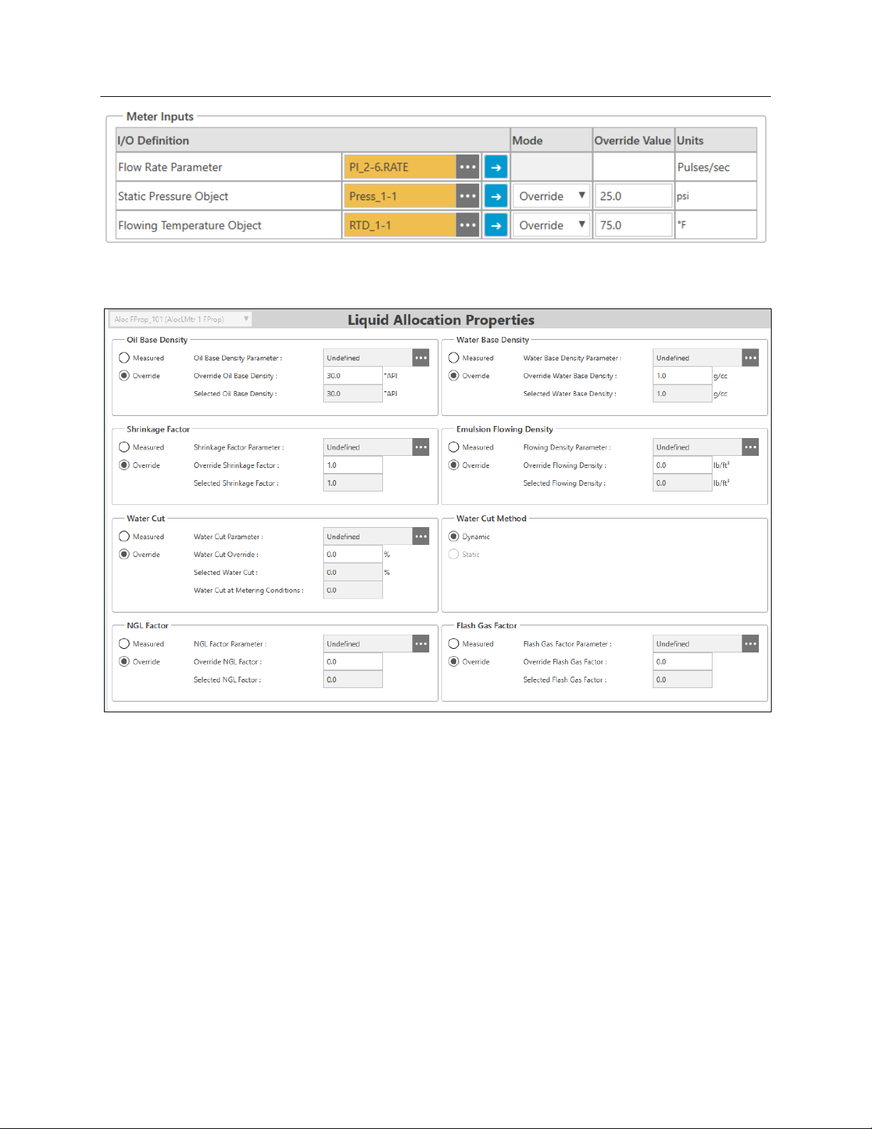
Click Next. The wizard displays the Liquid Allocation Meter screen, which you use to select
inputs for the liquid allocation meter.
First, enter 1000 as the K-factor.
For the Flow Rate Parameter, open the Point Picker and select PI_ > Liquid Meter (Instance
2-6) > Rate.
For the Pressure and Temperature, select the first 4088 instance (as you did with the first
meter):
FBxConnect 27
Page 32
Emerson FB3000 Separator Configuration Guide
D301884X012
October 2019
Notice that it shows the Override Values you already entered. Click Next. The wizard
displays the Liquid Allocation Properties screen.
Click Next. The wizard displays the Default Meter History Setup screen.
28 FBxConnect
Page 33
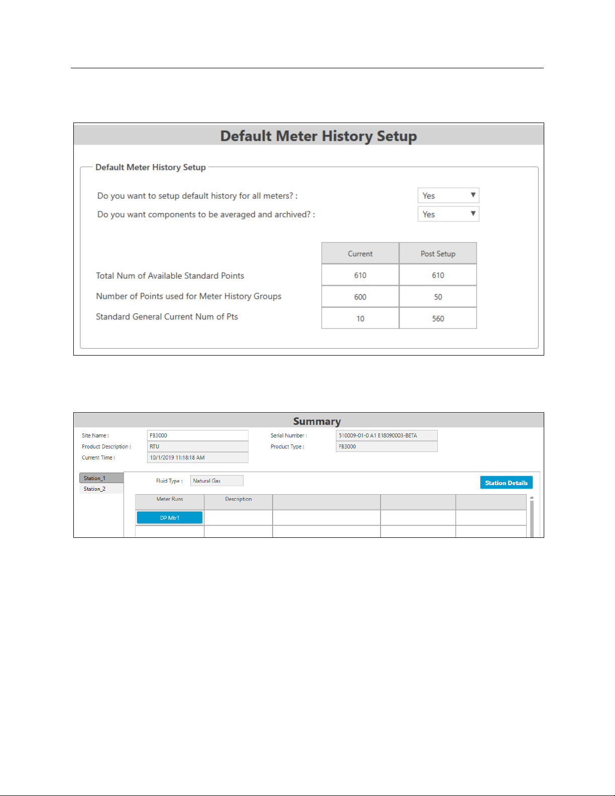
3.2.2 History & Summary
Use this screen to configure history for the meters.
Emerson FB3000 Separator Configuration Guide
D301884X012
October 2019
Keep the default settings and click Next. The wizard displays the Summary screen, which is
the final screen in the guided setup. From this point on, you can randomly select any
station or meter and change its settings or monitor its calculations.
When you are done reviewing your station and meters settings, click Finish. The system
displays the Configuration home page:
FBxConnect 29
Page 34
Emerson FB3000 Separator Configuration Guide
D301884X012
October 2019
You can directly access all the settings seen in the Guided Wizard from the Configure
menu. Notice that the GUI now includes buttons for the gas and liquid meters.
3.3 Math Blocks
You use math blocks to define calculations. Each math block has up to four inputs and
three calculations, which can each be saved to writable OPIs. The system performs math
block calculations once a second.
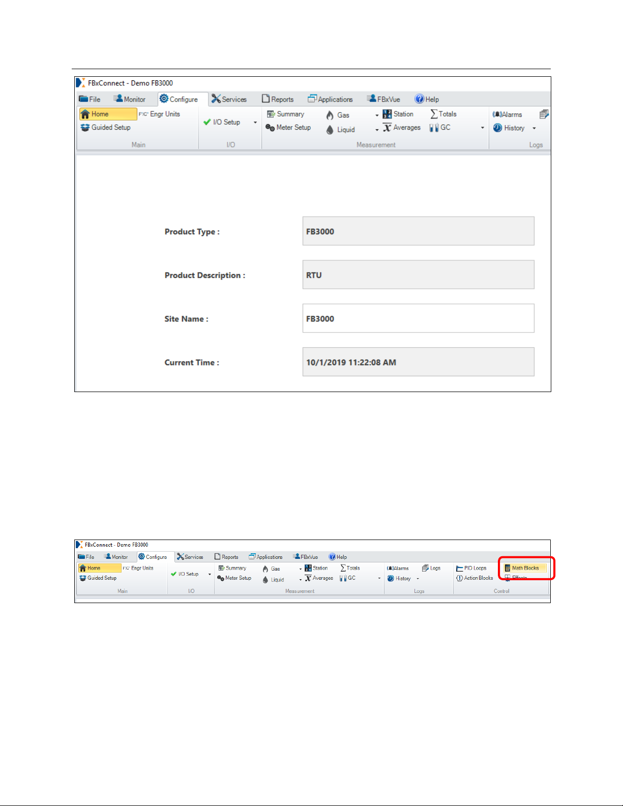
To configure math blocks, select the Configure tab and click the Math Blocks option:
The Math Blocks screen displays:
30 FBxConnect
Page 35
Emerson FB3000 Separator Configuration Guide
D301884X012
October 2019
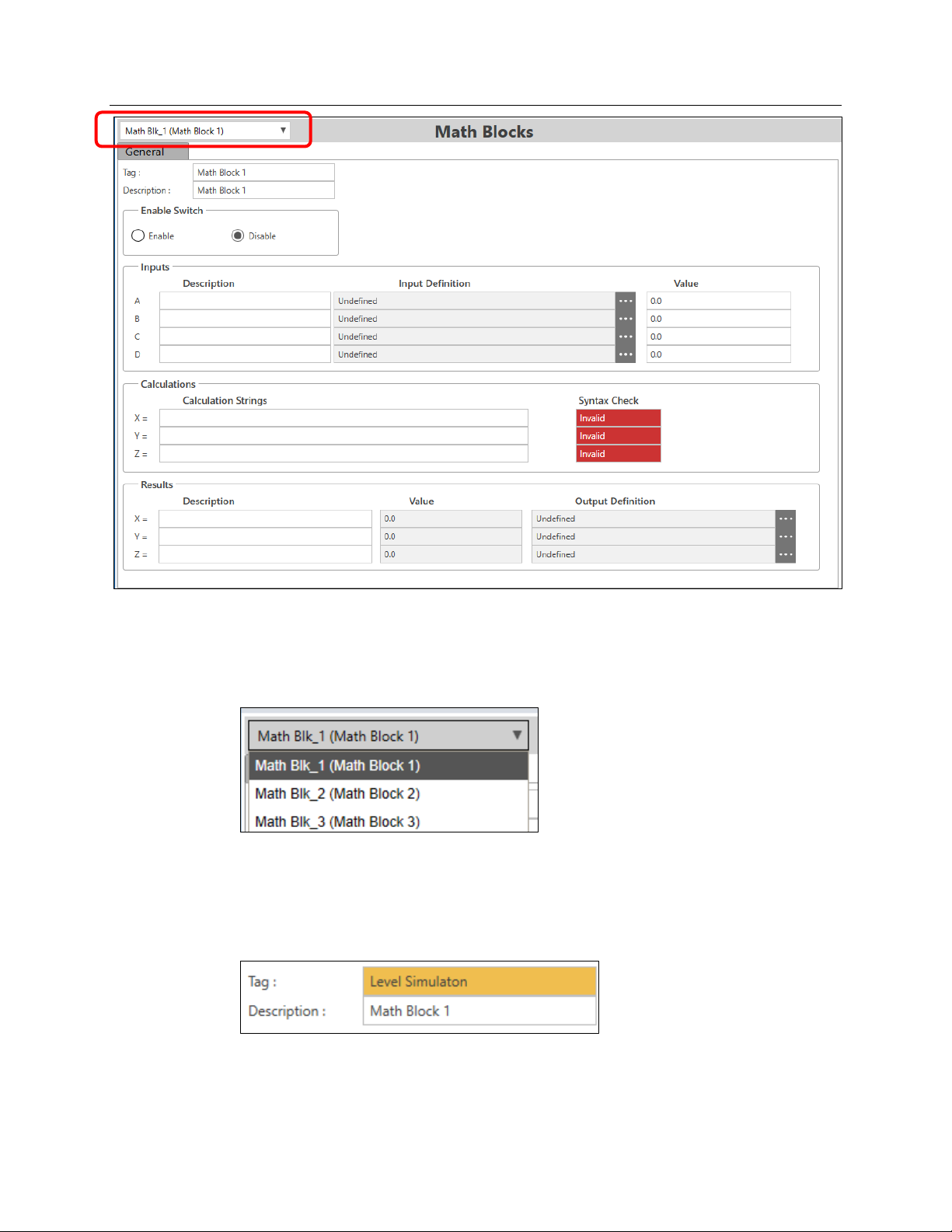
Note the drop-down menu option in the upper left-hand corner of the screen. Use it to
select the math block to define.
For this demo, we’ll define two math blocks: one to simulate the liquid level and another
to simulate the pressure:
3.3.1 Simulating Liquid Level
You use the first math block to simulate the liquid level in the separator.
Enter Level Simulation as the tag for Math Block 1.
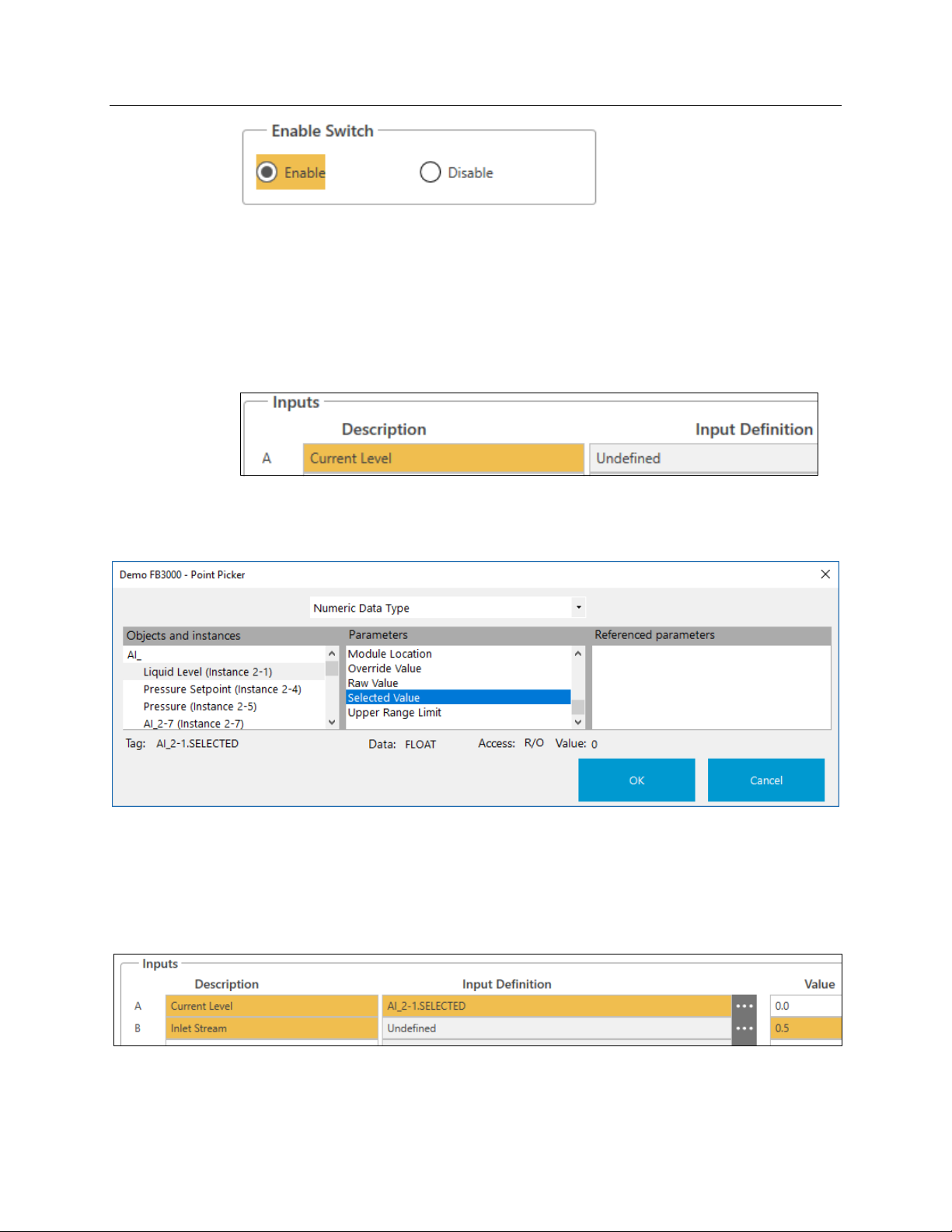
Notice that each control feature has an Enable Switch to turn it on/off. Select the Enable
option for this math block:
FBxConnect 31
Page 36
Emerson FB3000 Separator Configuration Guide
D301884X012
October 2019
To simulate the liquid level, you need to know the current level, how much the level is
rising due to the inlet stream (we’ll pick an arbitrary number), and how much the level is
falling due to the outlet control valve.
To define the inputs:
For Input A:
Enter Current Level as the Description.
Open the Point Picker.
Select AI_ > Liquid Level (Instance 2-1) > Selected Value.
The Selected Value of a point is equal to the live value when the operation mode is set to
Live and is equal to the override value when the operation mode is set to Override.
For Input B:
Enter Inlet Stream as the Description.
Enter 0.5 as the Value (do not open the Point Picker).
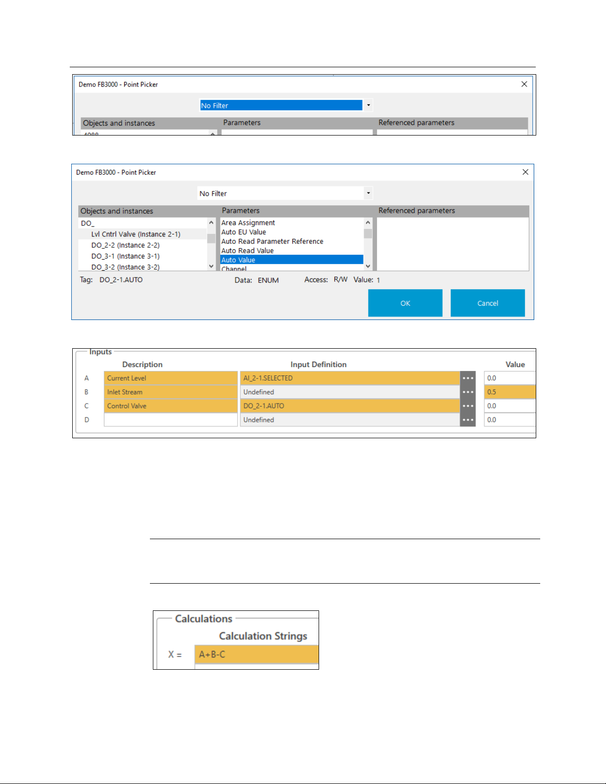
For Input C:
Enter Control Valve as the Description.
Open the Point Picker.
Select No Filter at the top of the Point Picker screen.
32 FBxConnect
Page 37
Emerson FB3000 Separator Configuration Guide
Select DO_ > Lvl Cntrl Valve (Instance 2-1) > Auto Value
D301884X012
October 2019
The inputs should now look like this:
With the inputs defined, we can now define the calculations.
The new, calculated level is the current level (Input A) plus the rise due to liquid entering
through the inlet stream (Input B, arbitrarily set to 0.5 inches per second)
due to liquid leaving through the control valve (Input C ). Since the control valve is 0 when
closed and 1 when open, we’ll just use that value so that it causes a fall of 1 inch per
second when open.
Note
This is not an accurate simulation that considers real-world variables like changes in
pressure. It is a simplified calculation intended
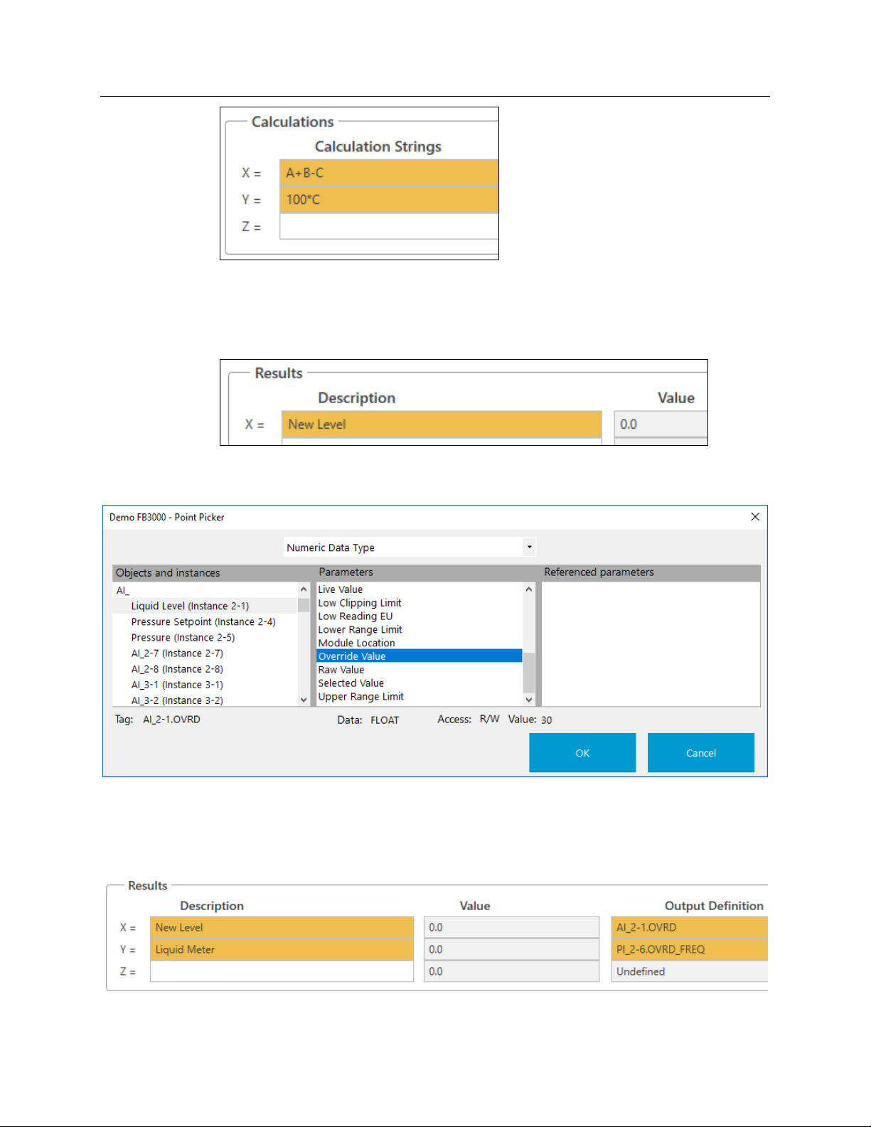
For the X calculation, enter A+B–C:
only for demonstration purposes.
minus the fall
Let’s also calculate a new pulse input for the liquid meter so that it is zero when the valve is
closed and 100 when the valve is open. For the Y calculation, Enter:
FBxConnect 33
100*C
Page 38
Emerson FB3000 Separator Configuration Guide
D301884X012
October 2019
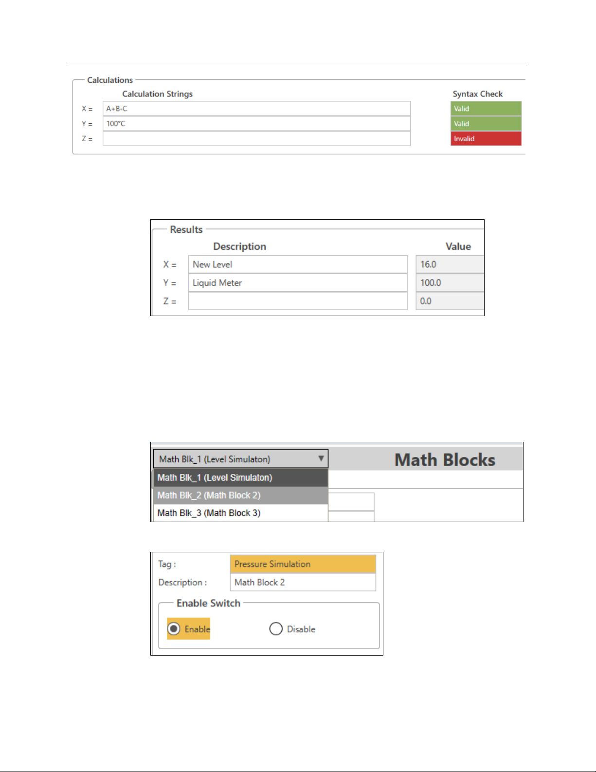
Then we need to store the results:
For Result X:
Enter New Level as the Description.
Open the Point Picker.
Select AI_ > Liquid Level (Instance 2-1) > Override Value.
For Result Y:
Enter Liquid Meter as the Description.
Open the Point Picker.
Select PI_ > Liquid Meter (Instance 2-6) > Override Frequency.
Click Save. At this point, the Syntax Check fields for both calculations should change to
green and display Valid:
34 FBxConnect
Page 39
Emerson FB3000 Separator Configuration Guide
D301884X012
October 2019
If they do not, there is a syntax error in the calculation that you need to correct.
Notice that that New Level value should start to drop from 30 because the Control Valve is
open.
All the liquid will drain out of the separator until we add controls to close the valve.
3.3.2 Simulating Pressure
You use the second math block to simulate the pressure in the separator, which is used to
module the gas control valve.
Select Math Blk_2 (Math Block 2) from the drop-down menu at the upper right of the
screen:
Enter Pressure Simulation as the Tag and enable the math block.
We simulate the pressure in the same way we simulated the liquid level. We need to know
the current pressure, how much the pressure increases due to an inlet stream, and how
much the pressure decreases due to the control valve.
FBxConnect 35
Page 40
Emerson FB3000 Separator Configuration Guide
D301884X012
October 2019
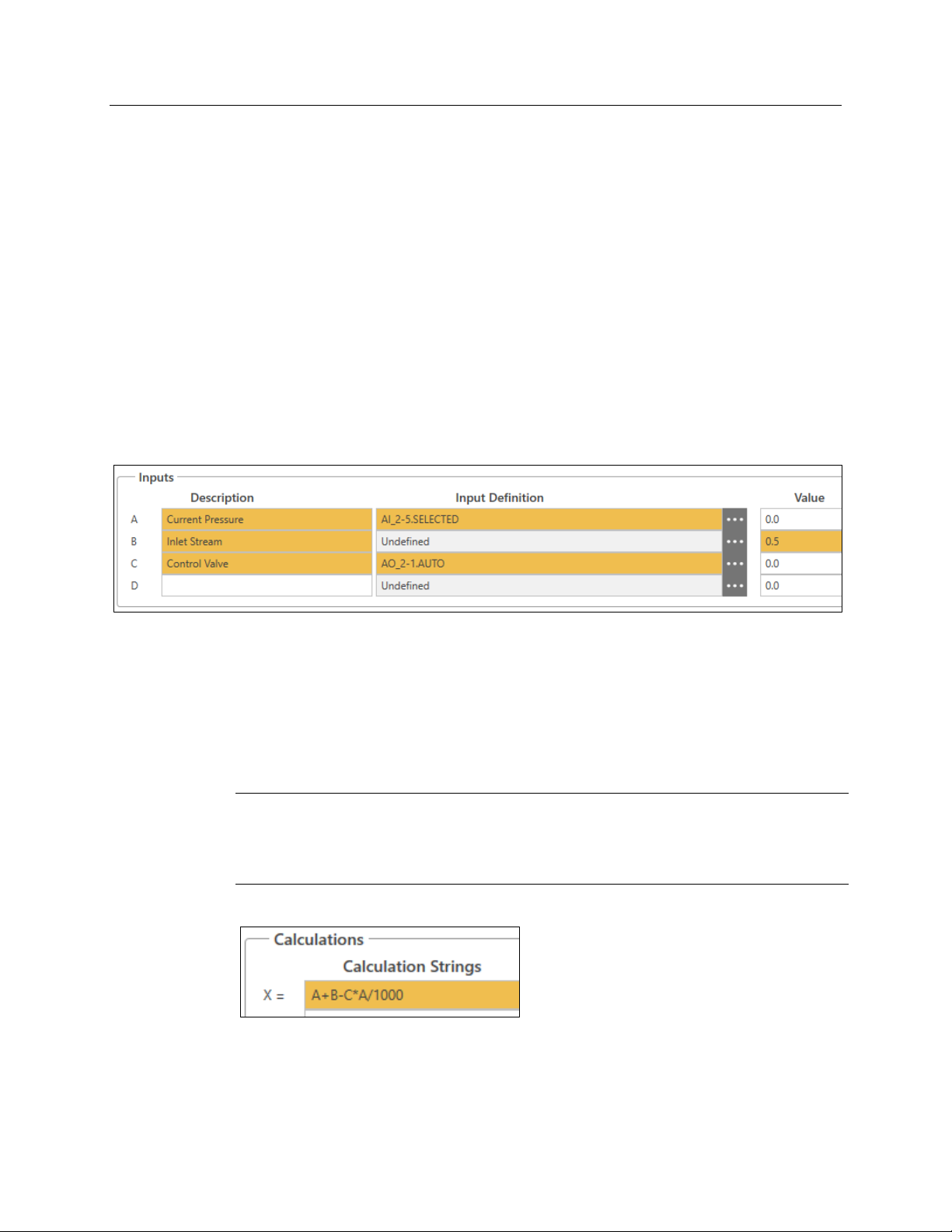
Define the inputs:
For Input A:
Enter Current Pressure as the Description.
Open the Point Picker.
Select AI_ > Pressure (Instance 2-5) > Selected Value.
For Input B:
Enter Inlet Stream as the Description.
Enter 0.5 as the Value.
For Input C:
Enter Control Valve as the Description.
Open the Point Picker.
Select AO_ > Gas Cntrl Valve (Instance 2-1) > Auto Value.
The inputs should look like this:
For this calculation we need to do something different from the control valve outlet, since
this is an analog output calculation that goes from 0 to 100% instead of from 0 to 1.
Additionally, gas compresses and responds to pressure changes much more than liquid, so
we need to account for that.
We approximate the outlet as the Control Valve % Open (Input C) multiplied by the
Current Pressure (Input A) and then divided by 1000 so that it’s about the same magnitude
as the inlet stream.
Note
This an even less-accurate simulation that the liquid simulation, since gas compression and
flow calculations are much more complex. Again, this is a simplified calculation intended
only for demonstration purposes.
So, for the X Calculation, enter A+B–C*A/1000:
Since we are calculating the pressure of the separator, we also need to update our 4088
static pressure that we’re using for our meters. Since the 4088 Pressure is in Absolute
pressure psi(a) and our input pressure is in Gauge Pressure psi(g), we need to add one
atmosphere of pressure (about 14.7 psi).
For the Y Calculation, enter X + 14.7:
36 FBxConnect
Page 41
Emerson FB3000 Separator Configuration Guide
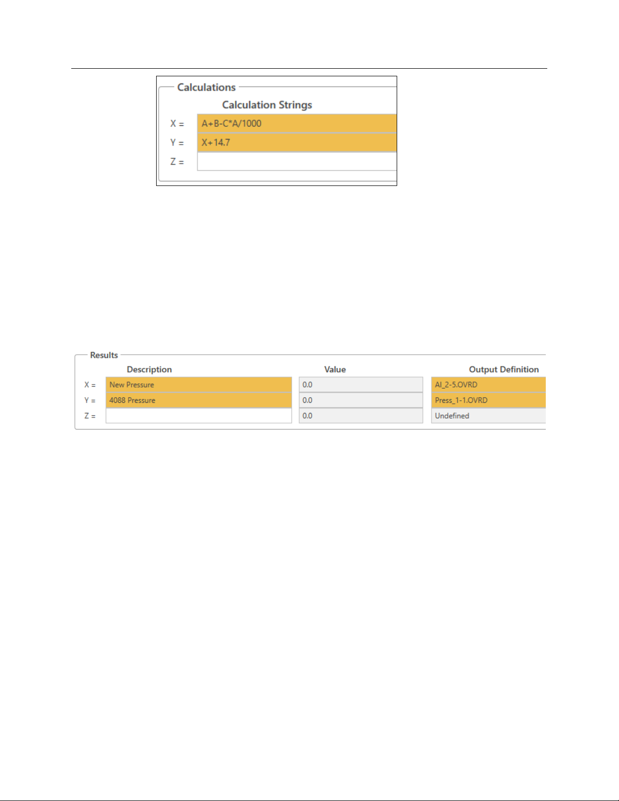
Now we store the results:
For Result X:
Enter New Pressure as the Description.
Open the Point Picker.
Select AI_ > Pressure (Instance 2-5) > Override Value.
For Result Y:
Enter 4088 Pressure as the Description.
Open the Point Picker.
Select Press_ > 4088B-1 Press (Instance 1-1) > Override Value.
D301884X012
October 2019
Click Save. Check that the values for the Syntax Checks are valid.
The pressure should now start to increase because the control valve is currently closed (0%
open).
FBxConnect 37
Page 42

Emerson FB3000 Separator Configuration Guide
D301884X012
October 2019
3.4 Action Blocks & Effects
Action blocks enable you to define simple logic operations. Each action bock checks if
some condition is true/valid and if it is, triggers some action or effect(s). An individual
action block can trigger different types of actions or multiple effects. You can also chain
action blocks logically.
Click Action Blocks on the Configure tab.
The Action Blocks screen displays:
Note that the drop-down menu in the upper left-hand side of the screen displays all
defined action blocks:
In this part of the demo we are going to use action blocks (and an effect) to simulate the DI
high-level and low-levels switches.
38 FBxConnect
Page 43

Emerson FB3000 Separator Configuration Guide
3.4.1 Simulating the High Level Switch
Enter High Level Switch as the tag for Action Blk_1 (Action Block 1) and enable the action
block.
Define the logic for the action block:
Enter Liquid Level as the Description of Variable 1.
Open the Point Picker for Variable 1.
Select AI_ > Liquid Level (Instance 2-1) > Selected Value.
D301884X012
October 2019
Select Greater Than as the Operator.
Enter 33 as the value for Variable 2.
Enter 1 as the Deadband EU.
Select Binary Action for Output Type Triggered.
FBxConnect 39
Page 44

Emerson FB3000 Separator Configuration Guide
D301884X012
October 2019
Open the Point Picker for Output Action Point.
Select DI_ > Hi Lvl Switch (Instance 2-2) > Override Value
Keep the default Boolean Behavior value of Force 1 True & O False.
Click Save.
3.4.2 Simulating the Low Level Switch
We use both an action block and an effect to simulate the Low Level Switch.
Select Action Blk_2 (Action Block 2) in the drop-down menu at the top right of the screen.
Enter Low Level Switch as the tag for Action Block 2 and enable the action block.
Define the logic for the action block:
Enter Liquid Level as the description for Variable 1.
Open the Point Picker for Variable 1.
Select AI_ > Liquid Level (Instance 2-1) > Selected Value.
Select Less Than as the Operator.
40 FBxConnect
Page 45

Emerson FB3000 Separator Configuration Guide
Enter 27 as the value of Variable 2.
Enter 1 as the Deadband EU.
Select Effect for Output Type Triggered.
Select Effect 1 as the Trip Effect Link.
D301884X012
October 2019
Click Save. Note that the value of the Basic Logic Block Status for the action block changes
to
ACTIVE because the separator is currently empty.
Next, we configure Effect 1.
Click Effects in the Configure Tab.
An effect writes a certain value to an OPI when active (and can also write a value when
inactive). Each effect can be triggered by any action block.
FBxConnect 41
Page 46

Emerson FB3000 Separator Configuration Guide
D301884X012
October 2019
Enter Low Level Switch as the tag for Effect 1 and enable the switch.
Define the effect:
Open the Point Picker for Output Definition and select No Filter.
Select DI_ > Lo Lvl Switch (Instance 2-3) > Override Value
Enter 1 as Output Active Value to Write
Keep Output Inactive Value to Write at 0 and Inactive Value Set Enable at Checked.
Keep Assert Behavior Continuously to Both States.
42 FBxConnect
Page 47

Click Save. Note that the value for Effect Status is now ACTIVE and it shows that the Low
Level Switch Action Block (2) triggered the effect. Also notice the Output Value (DI 2-3)
changes to 1.0
3.5 PID Loops
A PID loop is a common control loop feedback mechanism. Typically, a process variable is
compared to a setpoint and the error is used to calculate an output. Tuning parameters are
used to create the desired behavior, but there is a trade-off between responding quickly to
error and overshooting or causing oscillation.
Emerson FB3000 Separator Configuration Guide
D301884X012
October 2019
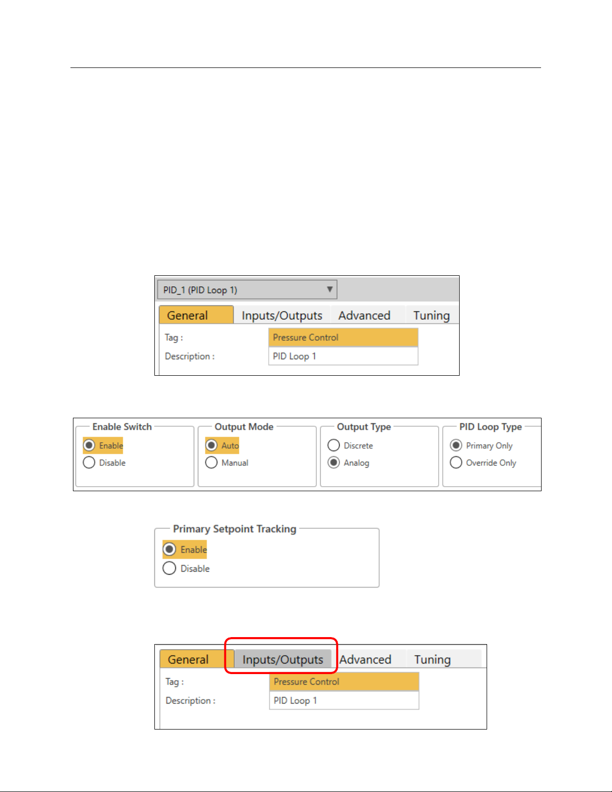
Click PID Loops in the Configure menu.
Each PID loop selection has four tabs:
FBxConnect 43
Page 48
Emerson FB3000 Separator Configuration Guide
D301884X012
October 2019
General:
Configures the main behavior of the PID.
Inputs/Outputs:
Sets the points and ranged of the variables.
Advanced:
Provides advanced behavior and control settings.
Tuning:
Sets basic tuning parameters and shows trending graph of the variables.
3.5.1 Controlling the Pressure
Our demo’s PID loop modulates the gas control valve to control the pressure of the
separator.
Enter Pressure Control as the tag for PID Loop 1:
Enable the PID loop, set the Output Mode to Auto, and keep the defaults of Auto for the
Output Type and
Enable Primary SetPoint Tracking:
Before saving, we need to finish configuring all the settings for the PID Loop.
Select the Inputs/Outputs tab.
Primary Only for the PID Loop Type.
44 FBxConnect
Page 49
Emerson FB3000 Separator Configuration Guide
D301884X012
October 2019
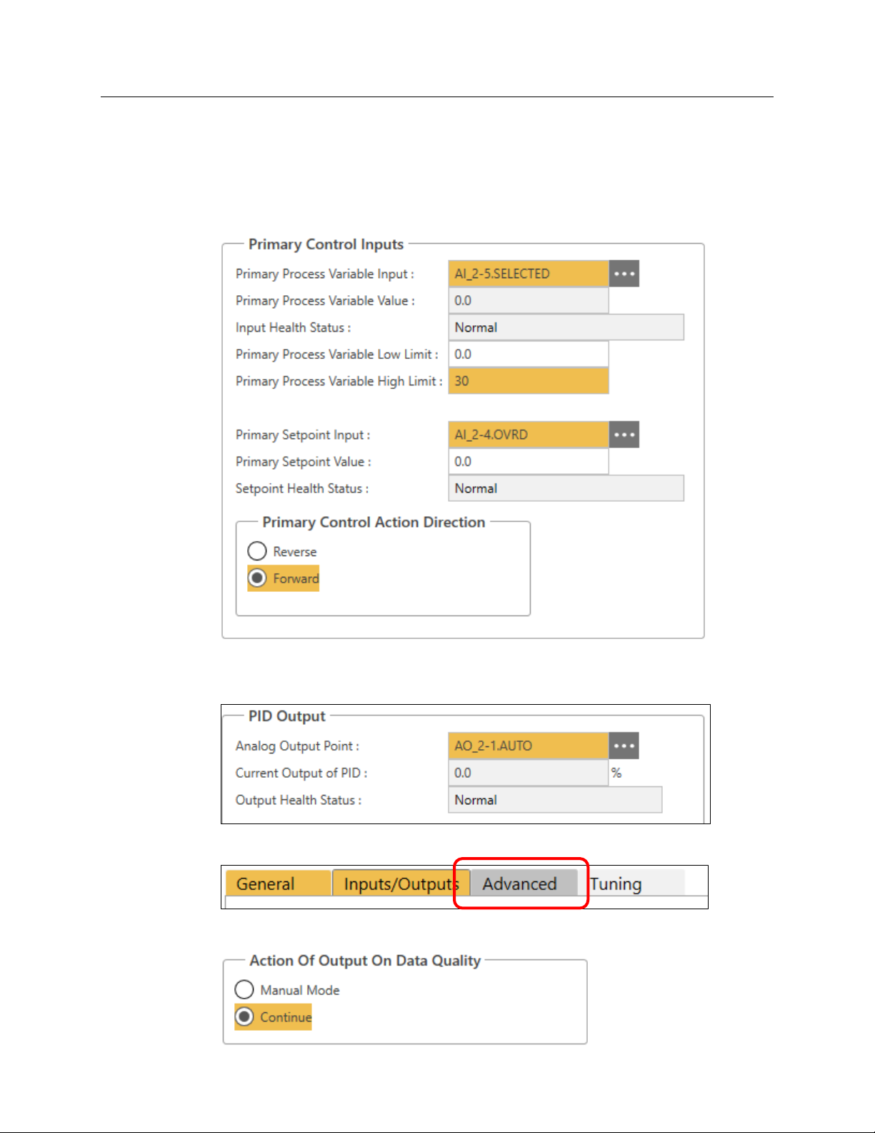
Open the Point Picker for Primary Process Variable Input and select AI_ > Pressure
(Instance 2-5) > Selected Value.
Enter 30 as the Primary Process Variable High Limit
Open the Point Picker for Primary Setpoint Input and select AI_ > Pressure Setpoint
(Instance 2-4) > Override Value
Select Forward as the Primary Control Action Direction.
Open the Point Picker for Analog Output Point and select AO_ > Gas Cntrl Valve (Instance
2-1) > Auto Value
Select the Advanced tab:
Select the Continue option for Action of Output on Data Quality:
FBxConnect 45
Page 50
Emerson FB3000 Separator Configuration Guide
D301884X012
October 2019
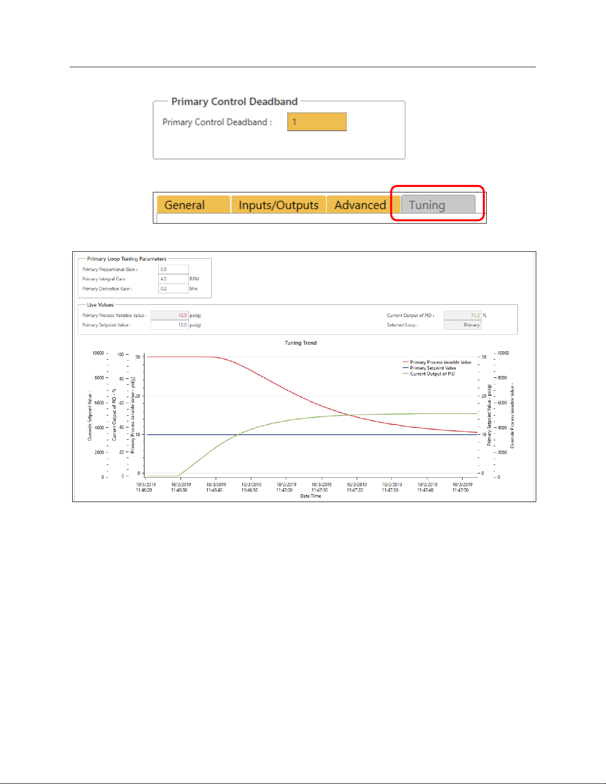
Enter 1 as the Primary Control Deadband:
Select the Tuning tab:
Click Save and observe the trend as the PID loop starts to control the pressure.
You can change the tuning parameters and see the changes in the behavior of the loop.
46 FBxConnect
Page 51
Emerson FB3000 Separator Configuration Guide
1
2
3
4
Chapter 4. FBxDesigner
FBxDesigner is an IEC61131 PLC programming environment separate from FBxConnect
than can be used to create more advanced control functions. FBxDesigner projects can be
downloaded to the RTU into application slots, along with graphical displays.
Note
FBxDesigner must be installed and licensed on your PC. For further information on this
product, refer to the FBxDesigner Quick Start Guide, part D301860X012)
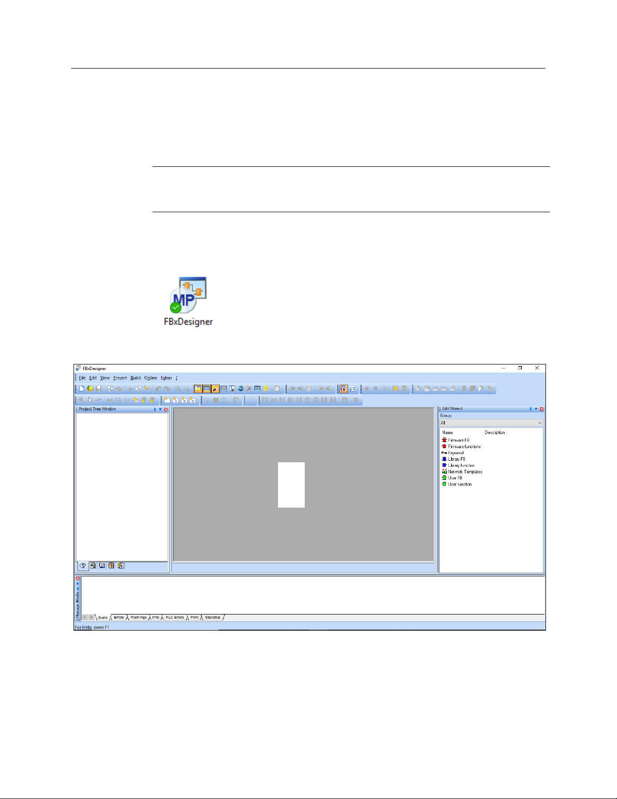
4.1 FBxDesigner Overview
Start FBxDesigner by clicking on the FBxDesigner desktop icon.
D301884X012
October 2019
The FBxDesigner workspace screen opens.
FBxDesigner is divided into several panels:
Project Tree Window (1): Shows all the components of the current project and enables
you to navigate to different locations and insert objects.
Edit Wizard (2): Shows a list of the functions/objects that can be added to a program.
Message Window (3): Shows status/results of user actions, such as errors in compiling.
Main Window (4): Provides an editing workspace for the active worksheet.
FBxDesigner 47
Page 52
Emerson FB3000 Separator Configuration Guide
D301884X012
October 2019
FBxDesigner Basics
An FBxDesigner project consists of one or more Program Organization Units (POUS)
and task(s).
POUs can be programs, functions, or function blocks.
POUs are composed of worksheets that contain comments, variables, and program
code.
Programs can use other functions and function blocks in their program code.
Program code is written in the IEC61131 languages (FDB, ST, LD, SFC, and IL).
A POU does not do anything until it is told to run by a task.
A task defines when to run program instances.
After making a project, you must compile it and create a boot project.
Once created, the boot project can be downloaded to the RTU
In this portion of the demo we are going to use FBxDesigner to create a simple project that
opens and closes the liquid level control valve based on whether the high- and low-level
switches are active.
Periodically Check the Project for Errors
When you are creating a project (and as you proceed through this guide), it is a good
practice to frequently check the project for errors as you add new sections of code and
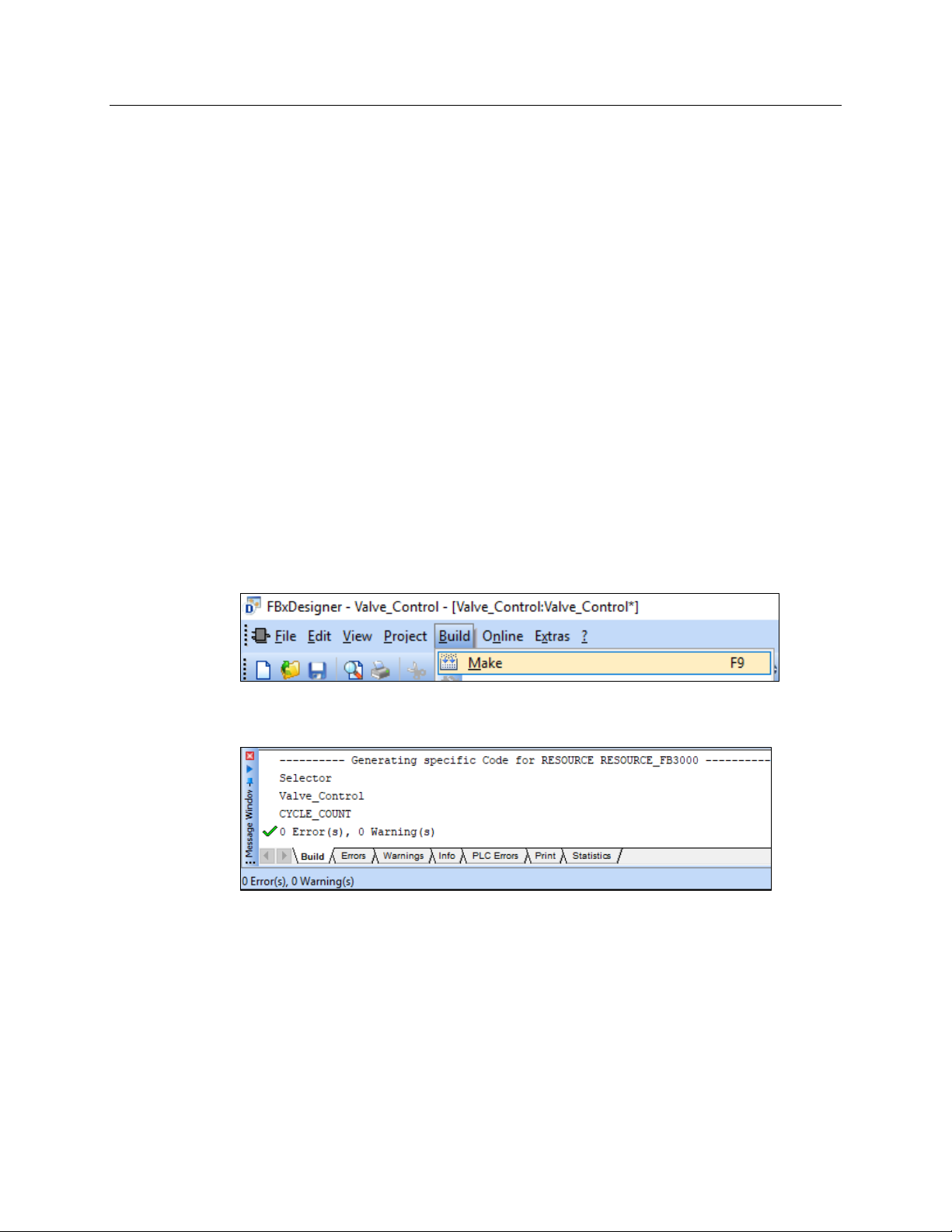
make changes. Click
for errors.
Build > Make on the top menu to compile the entire project and check
The Message Window on the bottom of the FBxDesigner screen displays any errors and
warnings that you must correct.
Errors are typically syntax mistakes, improper Data Type usage, or missing variables.
Warnings usually indicate that you have created something that is not being used.
48 FBxDesigner
Page 53
4.2 Creating a Project
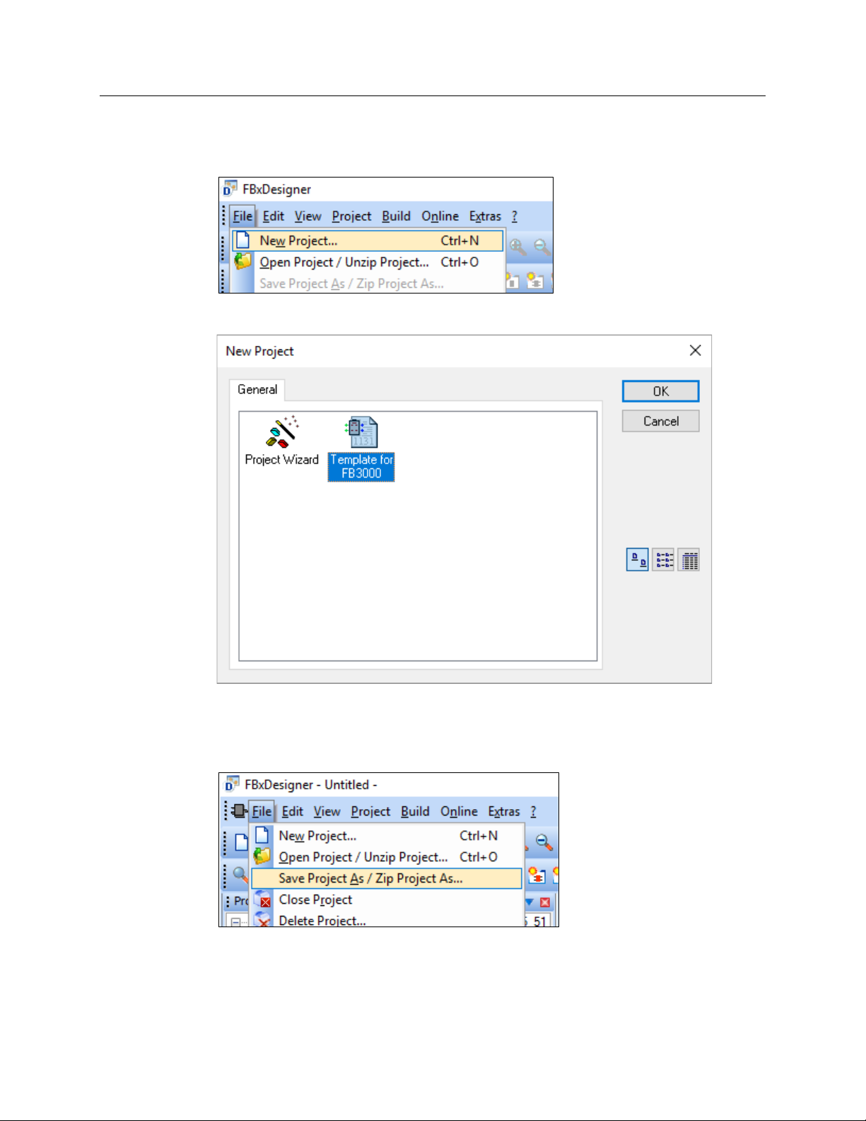
To start a project, click File > New Project on the menu in the upper left of the screen.
The New Project screen displays. Select Template for FB3000 and click OK.
Emerson FB3000 Separator Configuration Guide
D301884X012
October 2019
This creates a project with the configuration to run on an FB3000 RTU.
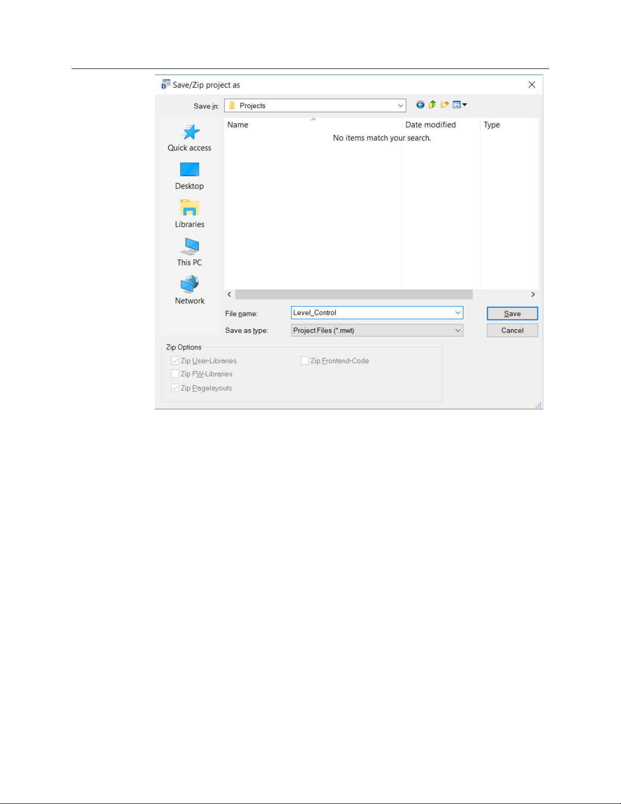
Before continuing any further, save the Project to give it a name and place in which to
store its associated files. On the FBxDesigner menu, click
Save this project as Level_Control in a location you can easily find later.
FBxDesigner 49
File > Save Project As.
Page 54
Emerson FB3000 Separator Configuration Guide
D301884X012
October 2019
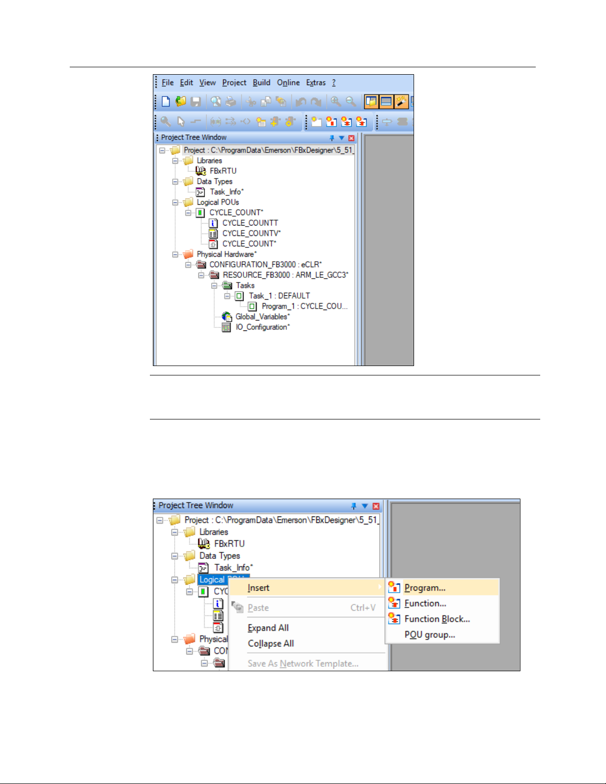
Note that the Project Tree window (on the left of the screen) has been populated with
objects:
50 FBxDesigner
Page 55
Emerson FB3000 Separator Configuration Guide
D301884X012
October 2019
Note
The system maintains an audit program called Cycle Count that tracks the number of
execution cycles the default task has run.
Now let’s start making our program.
4.2.1 Creating an FBD Program
To make a new program, right-click Logical POUs > Insert > Program:
The Insert screen displays.
FBxDesigner 51
Page 56
Emerson FB3000 Separator Configuration Guide
D301884X012
October 2019
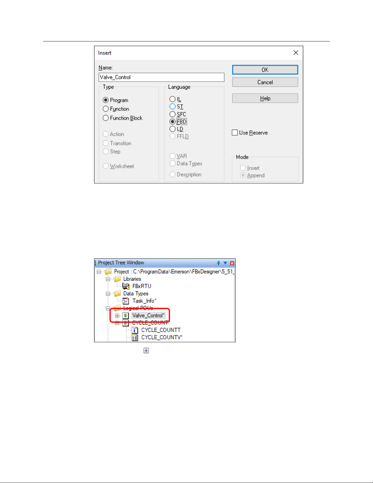
Enter Valve_Control (use the underscore; no spaces are allowed in project names) as the
Name.
Select FBD (Function Block Diagram) as the Language. FBD is a graphical “language” that
enables you to arrange function blocks on the screen and link them together like a flow
chart.
Click OK. The FBxDesigner screen displays; note that our Valve_Control project is now
listed as a Logical POU in the Project Tree Window.
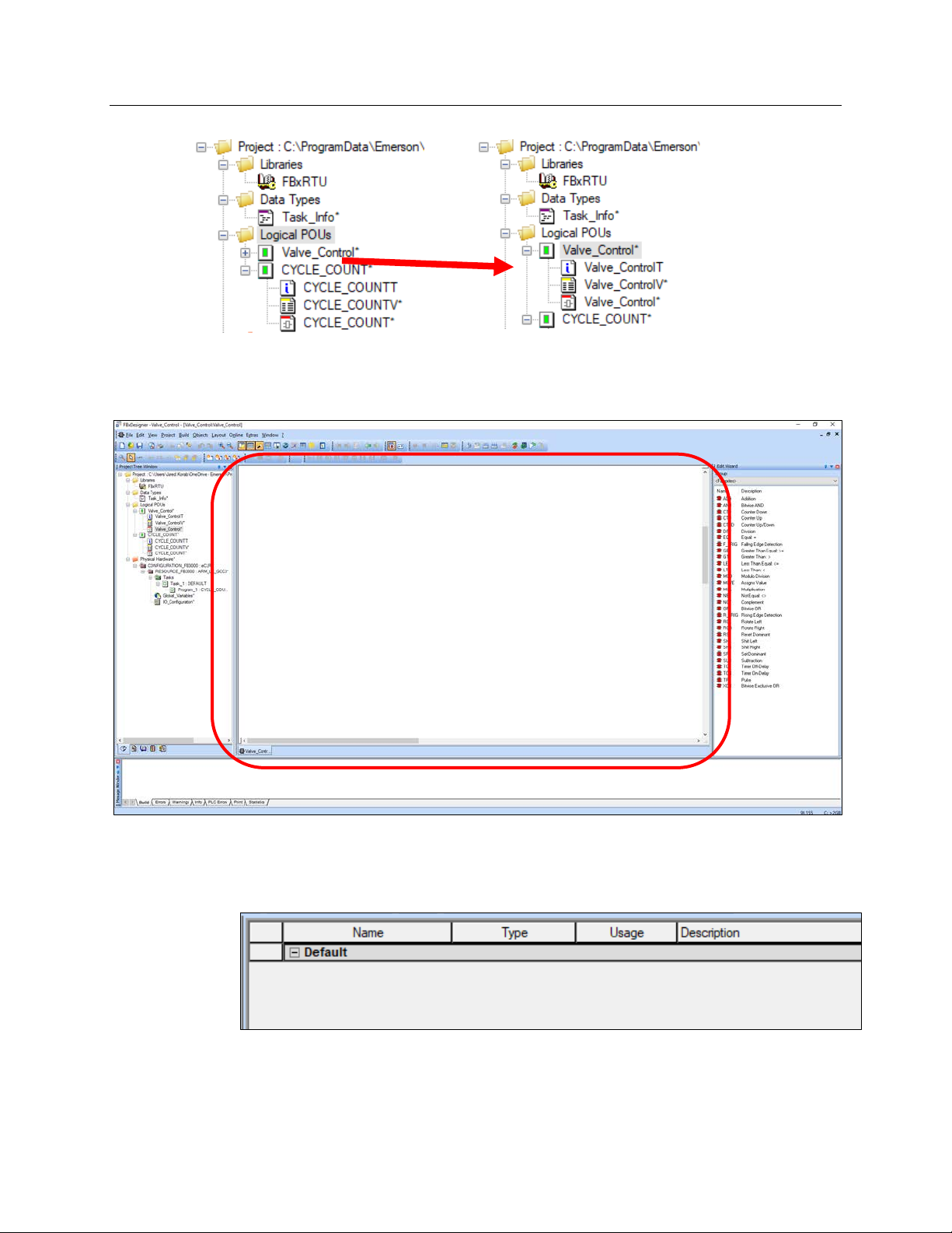
Click the plus sign ( ) next to the POU in the Project Tree to expand the POU and display
its component worksheets.
52 FBxDesigner
Page 57
Emerson FB3000 Separator Configuration Guide
D301884X012
October 2019
Double-click the first worksheet (Valve_ControlT). A blank worksheet opens in the central
pane on the FBxDesigner screen:
This first worksheet is just a text document that is used for comments. Use it to describe
the purpose and functionality of a program for future reference by other developers.
Double-click the second worksheet (Valve_ControlV) to open the Variables list.
Note that it is currently empty. FBxDesigner automatically populates this worksheet with
the variables and functions created as you build the program code in the third worksheet.
FBxDesigner 53
Page 58
Emerson FB3000 Separator Configuration Guide
D301884X012
October 2019
Note
If you created a variable or function that you ended up not using in the program, you should
delete it from this worksheet. You can also edit variable and functions if they are the wrong
type.
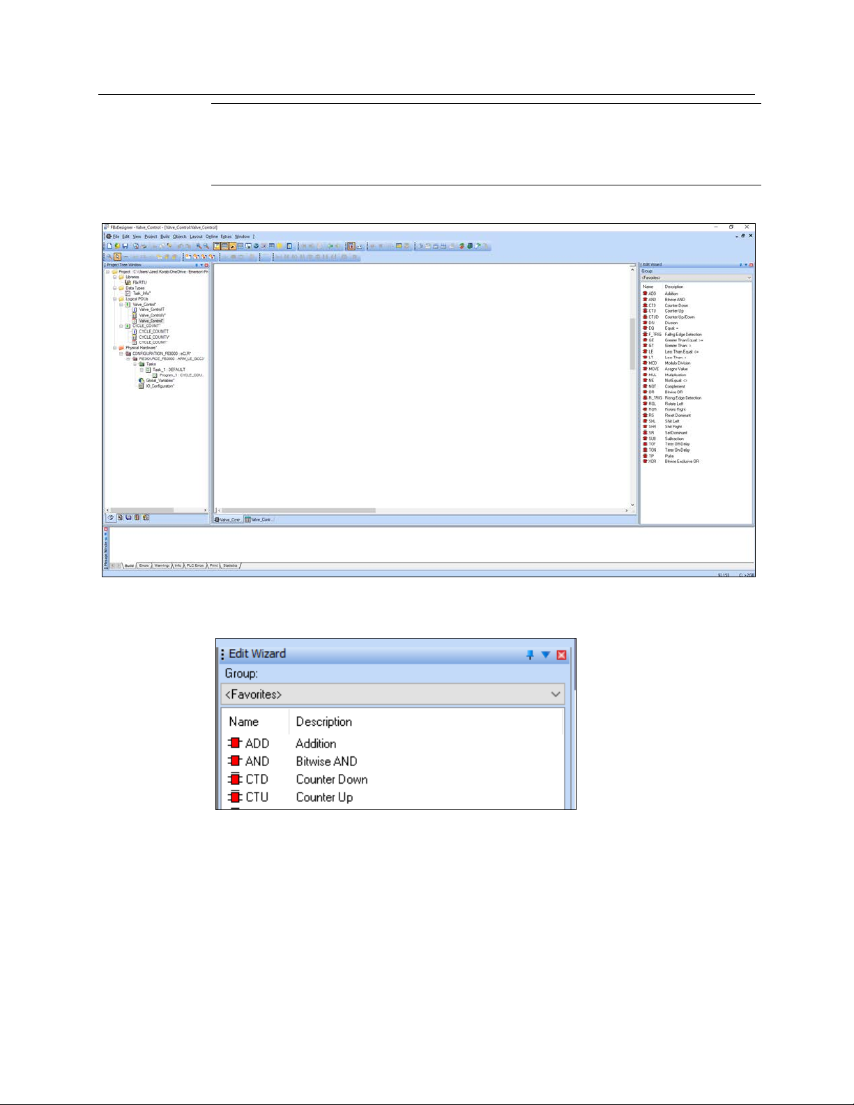
Double-click the third worksheet (Valve_Control) to open the Program Code.
This is where you write the actual program. Note that the Edit Wizard (at the right side of
the screen) has now populated with function blocks:
You use the Edit Wizard to find function blocks and add them to your program.
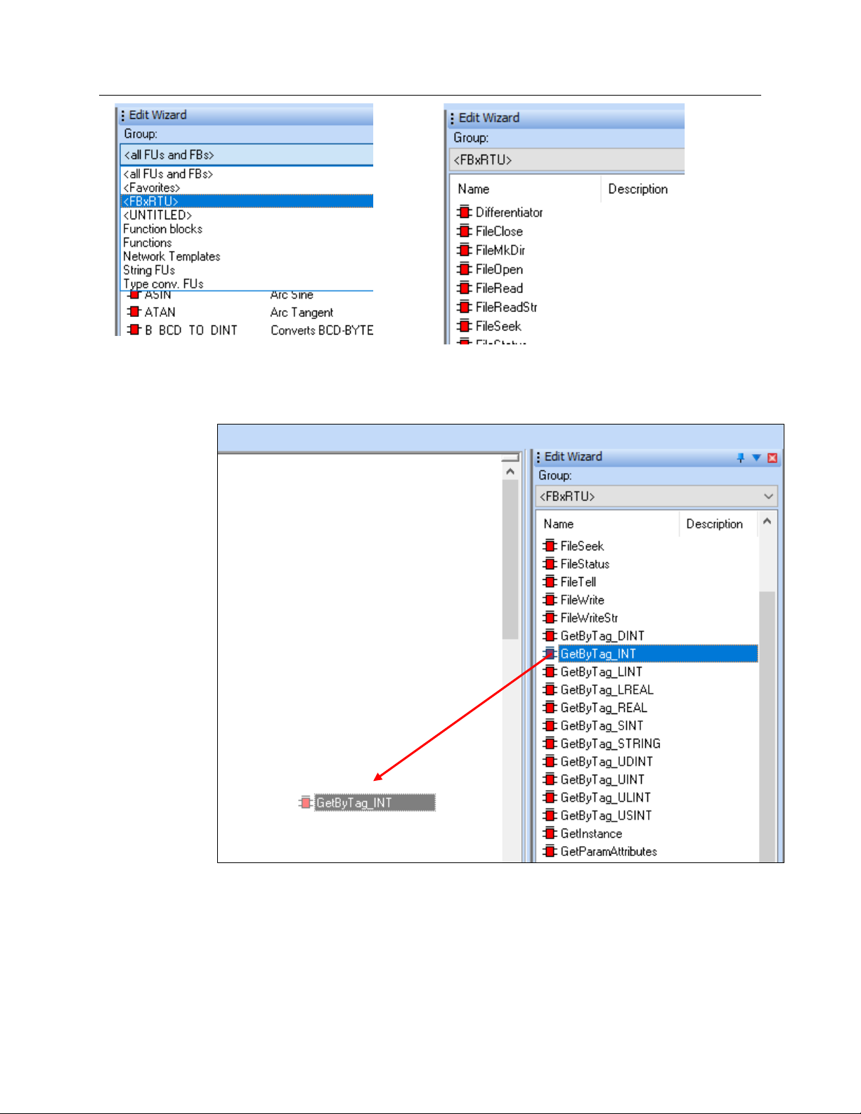
Select <FBxRTU> from the Group drop-down menu to see the function blocks that interact
directly with the FB3000.
54 FBxDesigner
Page 59
Emerson FB3000 Separator Configuration Guide
D301884X012
October 2019
In the <FBxRTU> group, find the GetByTag_INT function block and drag-and-drop it into
the main window.
The Variable Properties window opens (which occurs whenever you add a new variable or
function block to the program code):
FBxDesigner 55
Page 60

Emerson FB3000 Separator Configuration Guide
D301884X012
October 2019
Enter HighLevelSwitch as the name and click OK. This creates a function block in the main
window.
Notice that the GetByTag_INT Function Block has two inputs (on its left side) and three
outputs (on its right side). The input
output
Value is the tag’s value. The other inputs and outputs are not needed in this demo.
Tag tells the block what OPI point to find and the
56 FBxDesigner
Page 61

Emerson FB3000 Separator Configuration Guide
D301884X012
October 2019
Note
To learn more about a specific function block, right-click it and select Help on FB/FU:
Create a second GetByTag_Int function block and name it LowLevelSwitch.
Click-and-drag the second function block underneath the first:
Find the SetByTag_INT function block and add one, naming it SetValve. Arrange it to the
right of the first two, with space between them:
FBxDesigner 57
Page 62

Emerson FB3000 Separator Configuration Guide
D301884X012
October 2019
The SetByTag_INT function block is used to change the value of the DO controlling the
Liquid Level Control Valve.
Now let’s connect these function blocks to the tags. Double-click on the blue dot
connected to Tag on the first block.
The Variable Properties window opens again.
Instead of creating a variable name and then giving it the value of the tag, we can just
enter the value of the tag
and find the tag:
58 FBxDesigner
directly into the Name field as data. First, go back to FBxConnect
Page 63

Emerson FB3000 Separator Configuration Guide
D301884X012
October 2019
Open the Point Picker, select DI_ > Hi Lvl Switch (Instance 2-2) > Selected Value. Copy the
text that displays in the Tag field on the bottom left of the Point Picker.
Return to FBxDesigner, paste the copied text into the Name field of the Variable Properties
screen and bracket it with apostrophes (
The paired apostrophes ensure that FBxDesigner interprets the value as a string, which is
the data type required for the tag.
‘DI_2-2.SELECTED’):
Click OK.
Repeat this process for the other two tags. Select the Low Level Switch Selected Value tag
(as
‘DI-2-23.SELECTED’) for the second block and the Liquid Level Control Valve Auto Value
tag (as
‘DO-2-1.AUTO’) for the third block:
FBxDesigner 59
Page 64
Emerson FB3000 Separator Configuration Guide
D301884X012
October 2019
Now we need to define a function block in the middle to take the output values from the
first two blocks and determine what to send to the third block’s input value.
Let’s create a function block to do just that.
4.2.2 Creating an FBD Block with ST
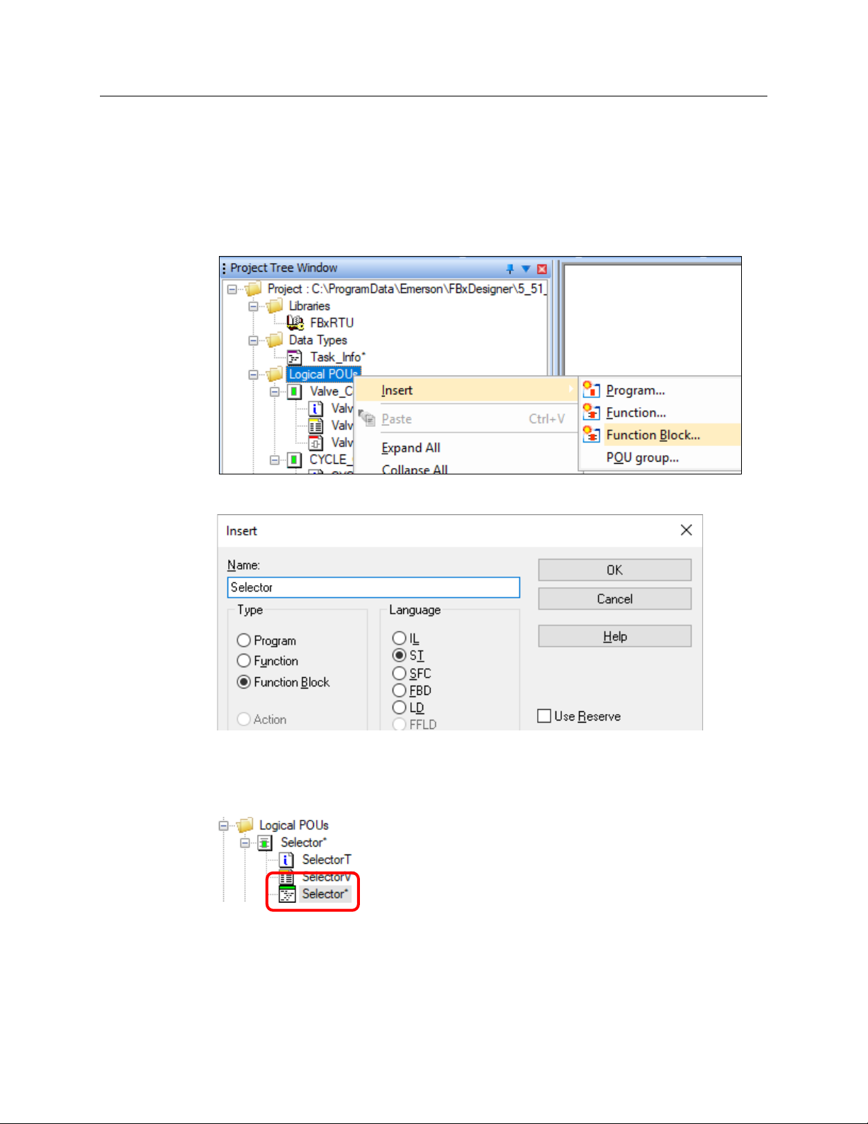
In the Project Tree Window, right-click Logical POU > Insert > Function Block.
The Insert screen displays.
Name the function block as Selector and select ST (Structured Text) as the Language
(Structured Text is a high-level textual language good for loops and calculations).
Double-click Selector to open the program code worksheet.
Note the it is a text worksheet rather than a graphical one like FBD.
60 FBxDesigner
Page 65

Emerson FB3000 Separator Configuration Guide
IF High = 1
…
D301884X012
October 2019
Let’s start programming. We want this function block to take in the statuses of the Highlevel and Low-level Switches and
close the valve (send 0) if the Low Level switch is active. If neither switch is active, the
function block should send no value so that the Valve status does not change.
Let’s start with an IF statement to check if the High_Level switch is active.
Enter:
open the valve (Send 1) if the High Level switch is active or
THEN
Valve := 1;
This checks if the High-Level Switch Input is equal to 1, and if it is, sends 1 to the Valve
output. If it is
Enter:
not equal to 1, we then need to check if the Low-Level Switch is active.
ELSIF Low = 1
FBxDesigner 61
THEN
Valve := 0;
END_IF;
Note that the IF statement must end with an END_IF statement.
Although we are done typing the code, we have not yet defined our variables. Essentially,
the program does not yet know what the words High, Low, and Valve mean.
Page 66
Emerson FB3000 Separator Configuration Guide
D301884X012
October 2019
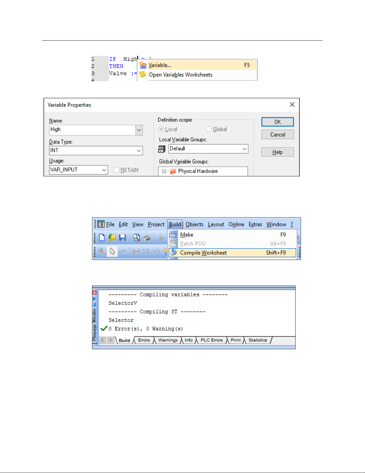
Right-click the word High and click Variable to open the Variable Properties window.
Select INT as the Data Type and select VAR_INPUT as the Usage. Click OK.
Repeat the process for the variables Low and Valve but indicate Valve as VAR_OUTPUT.
Finally, before leaving this worksheet, click Build > Compile Worksheet from the top menu.
This performs a check for any syntax errors or undefined variables in the code. Any errors
or warnings then appear in the Message Window at the bottom of the FBxDesigner screen:
Resolve any listed errors or warnings. Ensure that you have spelled all words correctly,
used punctuation as shown, and have defined all three variables.
62 FBxDesigner
Page 67
Emerson FB3000 Separator Configuration Guide
IF High = 1
END_IF;
D301884X012
October 2019
THEN
Valve := 1;
ELSIF Low = 1
THEN
Valve := 0;
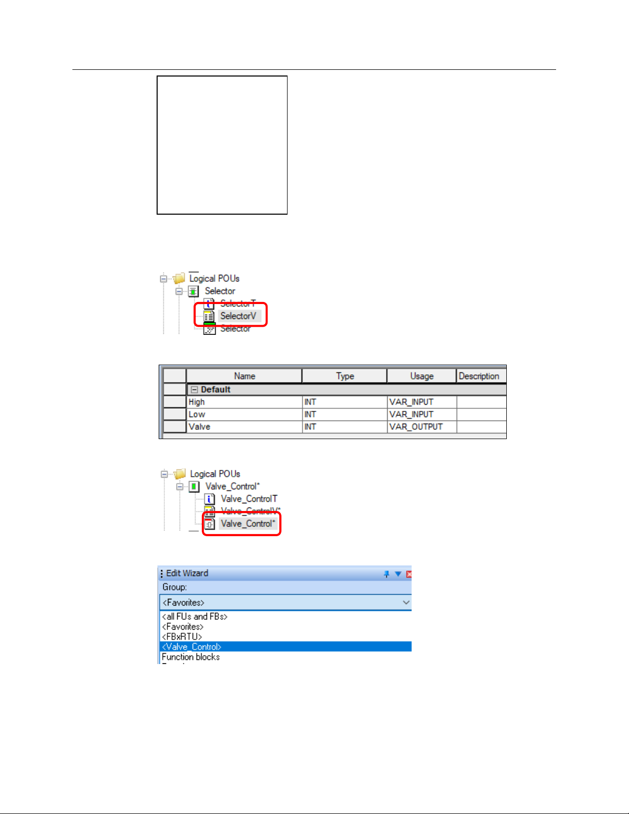
When you are done with the code, double-click the Variables worksheet of Selector
(
SelectorV):
You should now have three variables defined:
Double-click Valve_Control to redisplay the Code worksheet:
In the Edit Wizard, select the Group <Valve_Control>.
FBxDesigner 63
The <Valve_Control> group should now contain our newly defined function block:
Page 68
Emerson FB3000 Separator Configuration Guide
D301884X012
October 2019
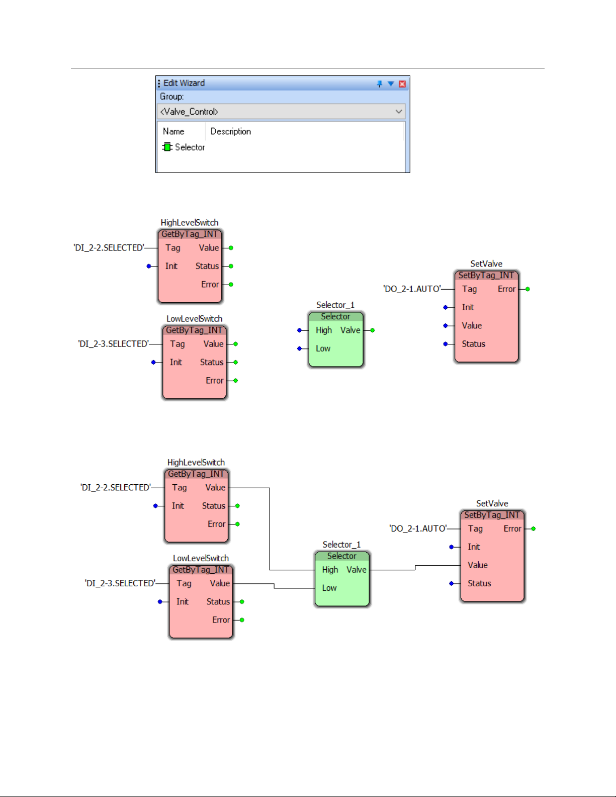
Click-and-drag to add a Selector function block in the middle of the program workspace.
Click
OK on the Variable Properties window. The workspace should now look like this:
Connect the function blocks as shown below, by clicking-and-dragging from the green
output dots to the blue inputs dots.
Click Build > Compile Worksheet to check for any errors or warnings.
Now we need to create a task to run an instance of this program.
64 FBxDesigner
Page 69
Emerson FB3000 Separator Configuration Guide
4.2.3 Tasks, Compiling, & BootProject
A task runs and executes programs. If you want to run any program, you must call that
program using a task.
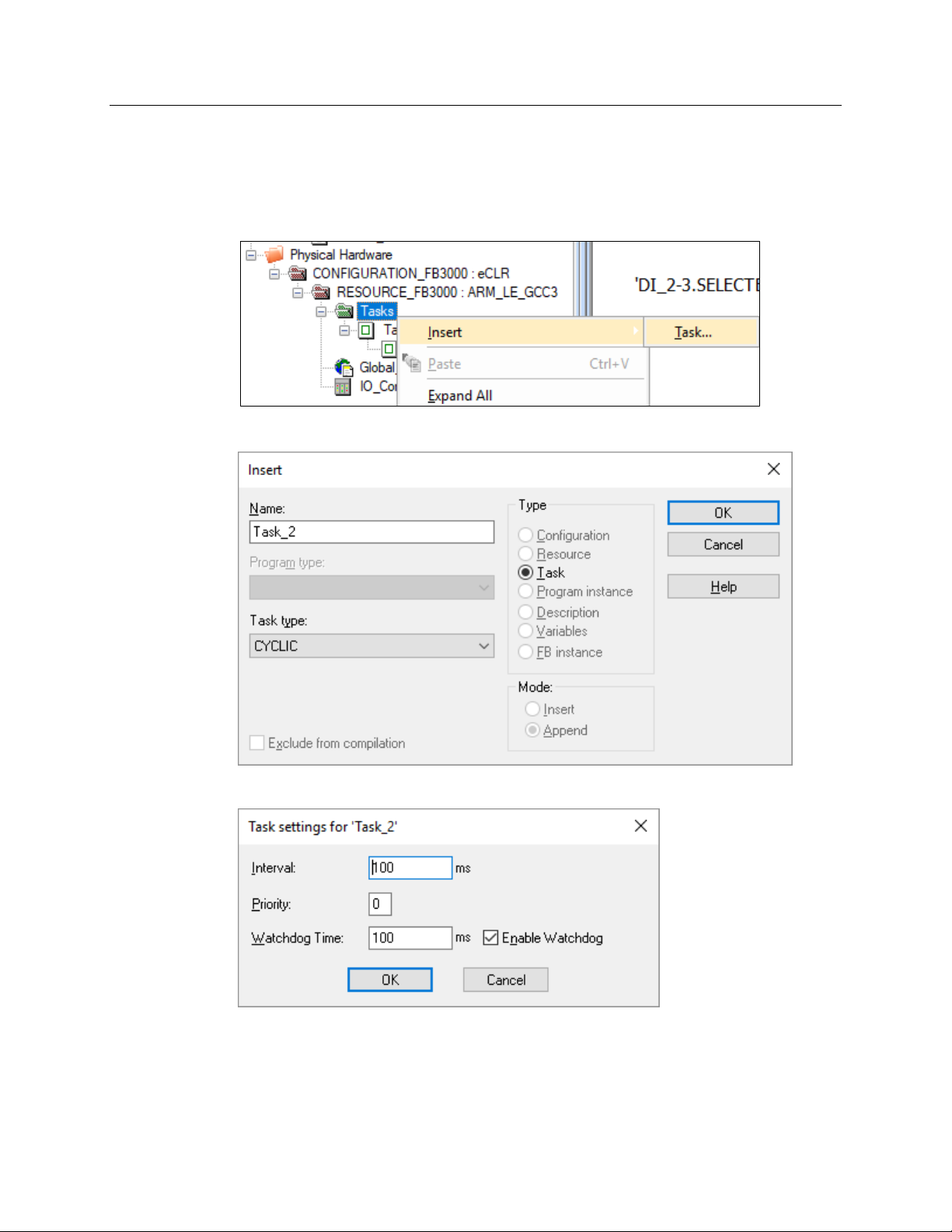
In the Project Tree window, right-click Tasks > Insert > Task.
The Insert screen displays.
D301884X012
October 2019
Enter Task_2 in the Name field and click OK. The Task settings screen displays.
If you define multiple tasks, you can change the execution time for the tasks and set
relative priorities. Click
FBxDesigner 65
OK. The FBxDesigner screen displays.
Page 70
Emerson FB3000 Separator Configuration Guide
D301884X012
October 2019
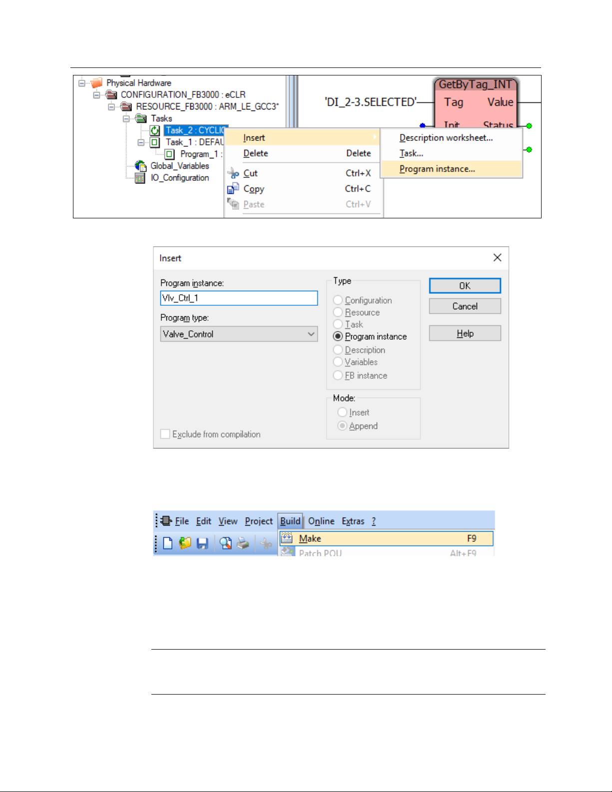
Right-click Task_2 and select Insert > Program instance. The Insert screen displays.
Name the Program Instance Vlv_Ctrl_1, select Valve_Control as the Program Type, and
click
OK. The FBxDesigner screen displays.
Select Build and click Make to compile the entire project.
If there are no errors, you have successfully made a project. Select Save the Project in the
top menu.
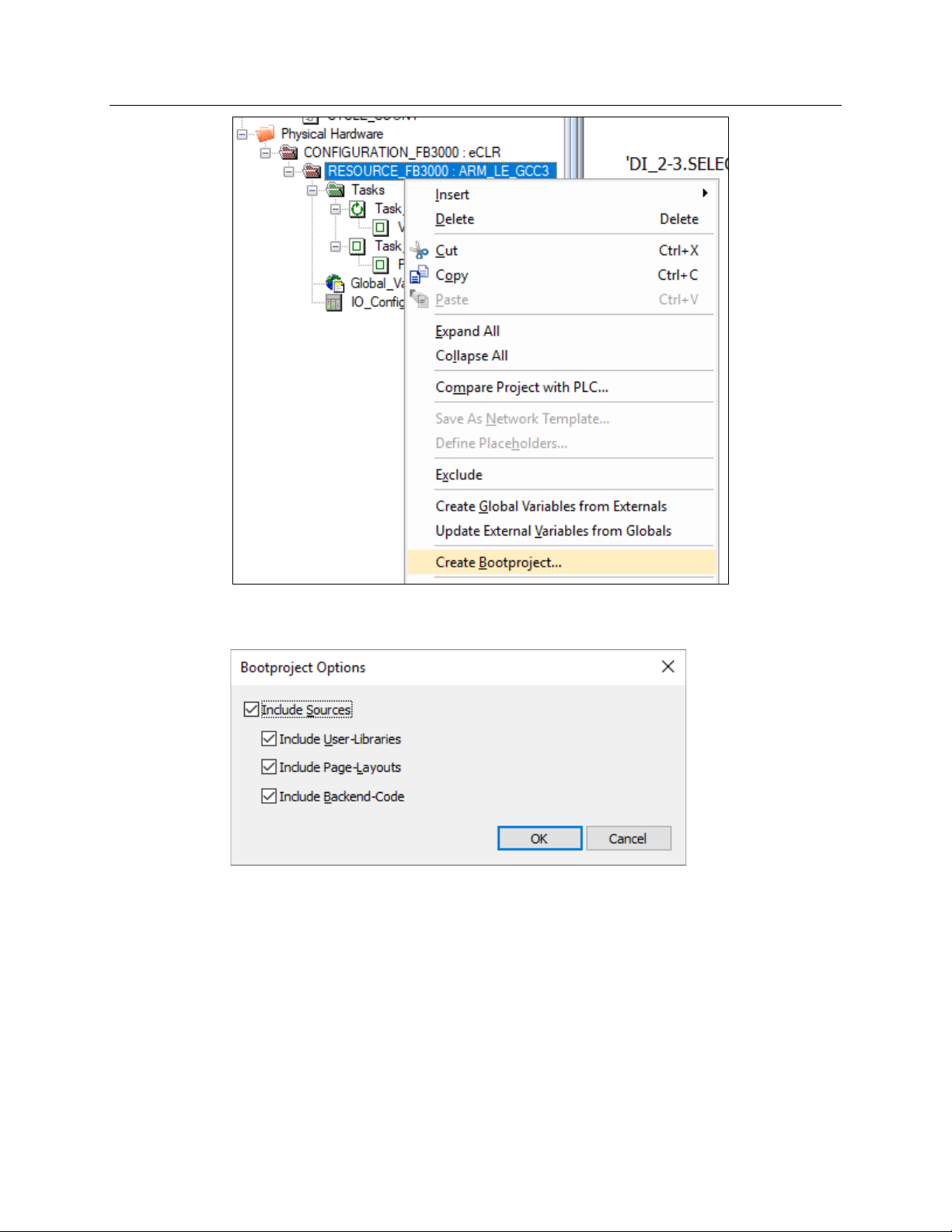
Now you need to make the boot project so it can be downloaded to the RTU.
In the Project Tree window, right-click RESOURCE_FB3000 : ARM_LE-GCC3… and select
Create Bootproject.
Note
This menu option is unavailable if you have made uncompiled changes. You must compile
your project before continuing.
66 FBxDesigner
Page 71
Emerson FB3000 Separator Configuration Guide
D301884X012
October 2019
The Bootproject Options screen displays. You can include the source code with the
downloaded application.
If you choose to include the source code, someone with access to the RTU and
FBxDesigner can download this FBxDesigner project from the installed application and edit
it. If you do not include the source code, then the application cannot be looked into or
edited from the RTU.
Click OK. Once FBxDesigner completes the bootproject, the project is ready for download
to the RTU. Refer to Section 6, Applications in this guide for further information on
downloading a project.
FBxDesigner 67
Page 72

Emerson FB3000 Separator Configuration Guide
D301884X012
October 2019
68 FBxDesigner
Page 73
Chapter 5. FBxVue
FBxVue is a graphical display builder included as part of FBxConnect. All the screens in
FBxConnect can be created with FBxVue.
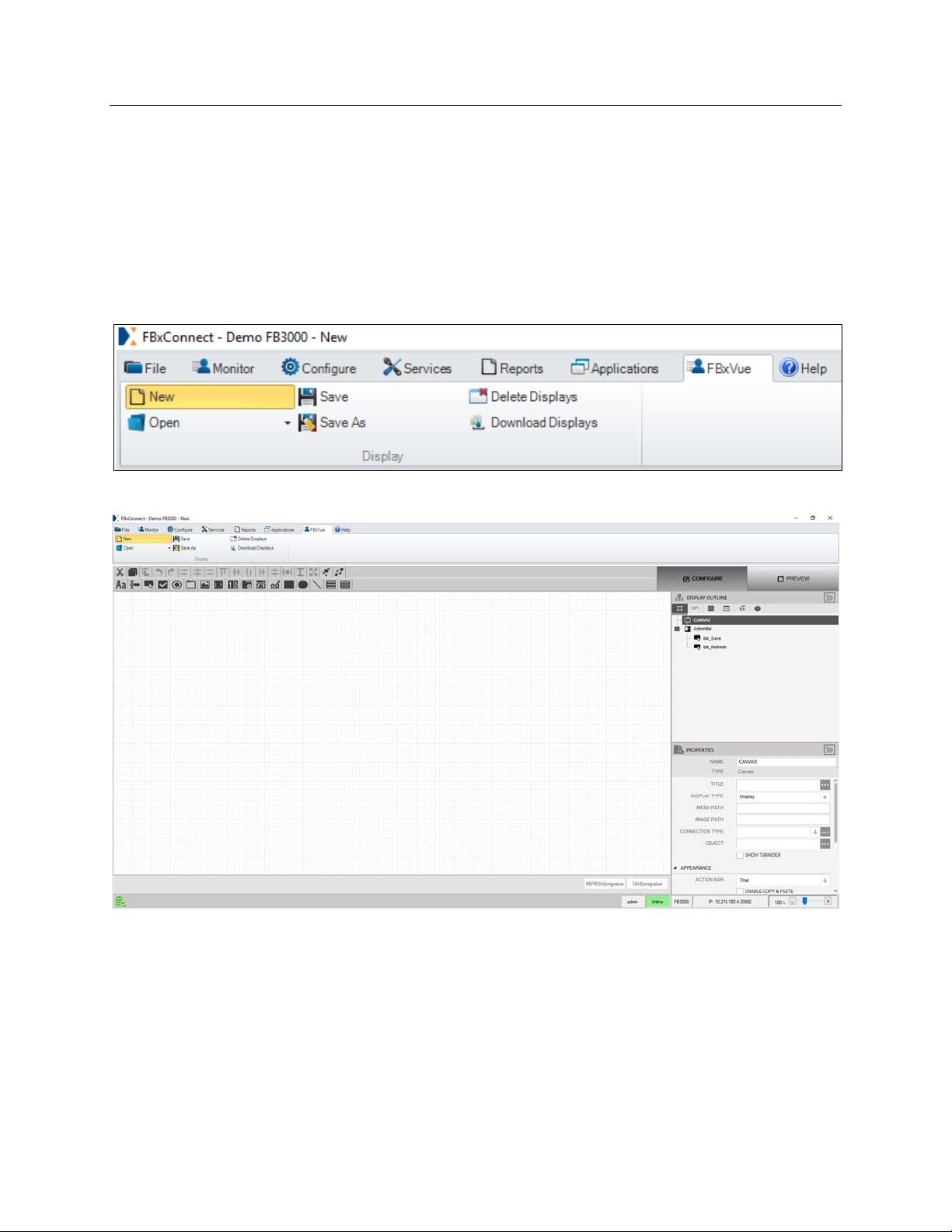
5.1 FBxVue Overview
Select the FBxVue tab in FBxConnect and then click New to create a new display.
The FBxConnect workspace screen displays.
Emerson FB3000 Separator Configuration Guide
D301884X012
October 2019
FBxVue consist of these sections:
Developer Toolbar: On top, contains Layout buttons to manage the position and
appearance of controls, and Control buttons to add controls to the display.
Canvas: Main work space where you add controls to.
Action Bar: Has buttons on the bottom of the Display such as Save and Refresh.
Configure/Preview: Buttons located on the top right to toggle editing/viewing.
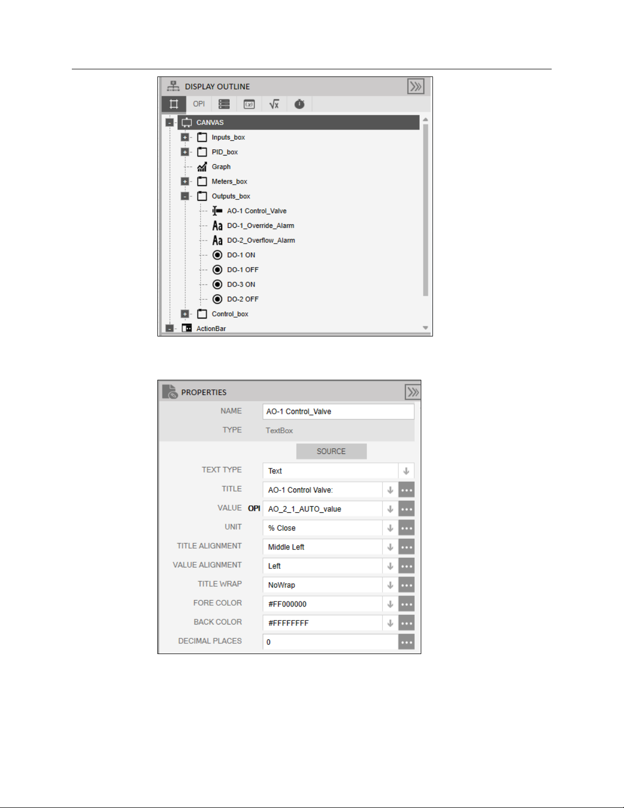
Display Outline: Menu on the middle right, used for organizing & selecting controls.
Properties Pane: Menu on the bottom right, used for editing the selected control.
FBxVue 69
Page 74

Emerson FB3000 Separator Configuration Guide
D301884X012
October 2019
The layout buttons in the Developer Toolbar enable you to manage the position and
appearance of controls:
Cut / Copy / Paste
Undo / Redo
Align Selected Objects by Left / Centers / Right / Top / Bottom
Make Spacing Equal Horizontally / Vertically
Make selected Objects the same Width / Height / Both
Bring selected Object to Front / Back layer
Use the control buttons in the Developer Toolbar to create new controls:
Label: Shows text, used to label objects.
TextBox: Shows the name, value, and units of an OPI. Allows the user to enter a new
value if the OPI is writable.
Button: A button that evaluates an expression when clicked.
Checkbox: Allows multiple entries to be selected at once.
GroupBox: A frame that can hold multiple controls inside it.
Properties Pane: Menu on the right, used for editing the objects in the display.
NumericUpDown: Allows you to select an object from a numbered list.
TabControl: A frame that has tabs on top to allow multiple pages in the same space.
Gauge: Shows a value visually.
Chart: Can plot multiple values over time.
Rectangle / Ellipse / Line: simple shapes.
Accordion: A collapsible menu that can show multiple objects.
Grid: A grid for displaying objects.
Use the Preview mode while building the display to see how the controls will look on the
finished display.
The Display Outline screen contains all the controls, OPIs, data sources, variable,
expressions, and timers associated with the current display.
70 FBxVue
Page 75
Emerson FB3000 Separator Configuration Guide
D301884X012
October 2019
The Properties window allows you to edit the available properties of a selected control, or
of the canvas itself. The properties available depend on the type of control selected.
FBxVue 71
Page 76

Emerson FB3000 Separator Configuration Guide
D301884X012
October 2019
5.2 Building a Display with FBxVue
In this section, we build a display to show:
A graphic of the liquid level in the separator tank
Pressure Gauge & Pressure Setpoint
Chart showing Trend line of Liquid Level and Liquid Meter Flow rate
Valve Statuses and Meter Flow Rates
This is what the final display should look like:
First, give the display a title. With Canvas selected in the Display Outline, enter Separator
Display as the Title in the Properties window.
72 FBxVue
Page 77

Emerson FB3000 Separator Configuration Guide
D301884X012
October 2019
Open the Point Picker for Title Style in the Appearance section of the Properties window.
Select Display Title so that the title will be big and bold. Click OK.
FBxVue 73
Page 78

Emerson FB3000 Separator Configuration Guide
D301884X012
October 2019
Click Preview on the top right to see what the title will look like.
The Separator Display title should appear at the top:
74 FBxVue
Page 79

Emerson FB3000 Separator Configuration Guide
D301884X012
October 2019
Click Configure (next to Preview) to return to editing.
Note
Preview the display frequently as you add controls to test their appearance and
functionality.
Let’s add the graphic of the separator. Click the Image button on the Developer
toolbar.
Click-and0drag over the left area of the canvas, as shown below.
With the Image selected (it will appear yellow and be highlighted in the Display outline),
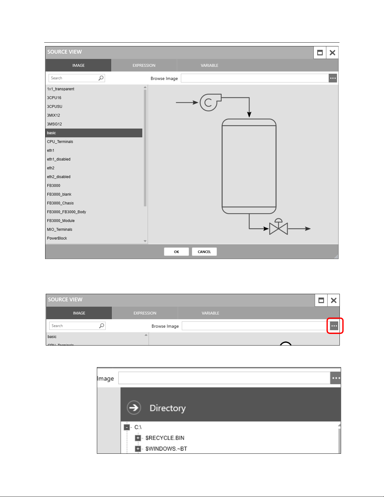
click on the Point Picker for Source in the Properties Window
A Source View window opens with a list of images on the left-hand side:
FBxVue 75
Page 80
Emerson FB3000 Separator Configuration Guide
D301884X012
October 2019
You can select from one of the Separator images included in the list, or you can include any
picture you have on your PC. To select a picture from your PC, click on the Point Picker in
the Browse Image field:
This opens a directory to your PC that you can use to browse to an image you have ready.
76 FBxVue
Page 81
Emerson FB3000 Separator Configuration Guide
Sep_icon
Sep_icon_2.png
D301884X012
October 2019
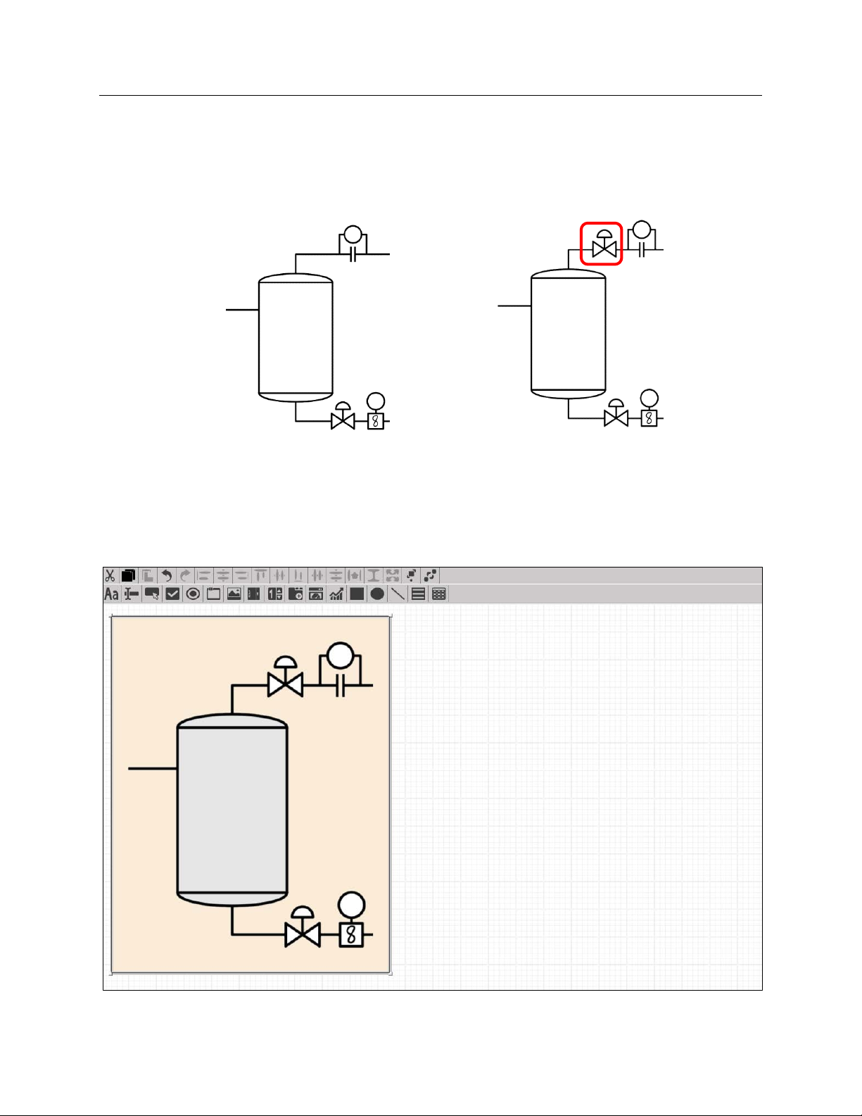
This document should be packaged inside a demo folder than includes the image
Sep_icon_2.png, located inside the Display/Images folder.
You can either choose the Sep_icon image that is included in FBxVue or browse for the
Sep_icon_2.png image in the Directory. The only difference is the presence of a valve for
the gas stream.
(included in FBxVue)
The display should look like this. To move or resize the image, click and drag on it or its
corners.
(included with this guide)
Now we can add a rectangle object over the separator tank that shows the liquid level
height.
FBxVue 77
Page 82
Emerson FB3000 Separator Configuration Guide
D301884X012
October 2019
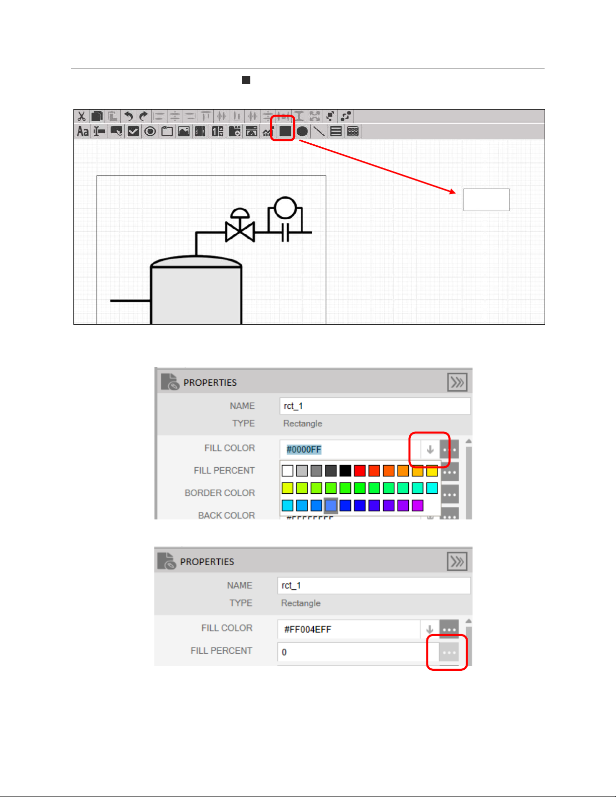
Click the Rectangle ( ) icon and click somewhere on the blank portion of the canvas to
create a rectangle:
With the Rectangle selected, on the Properties window, click the down arrow for Fill Color
and select a color to represent the liquid:
Click the Point Picker button for Fill Percent.
78 FBxVue
Page 83
Emerson FB3000 Separator Configuration Guide
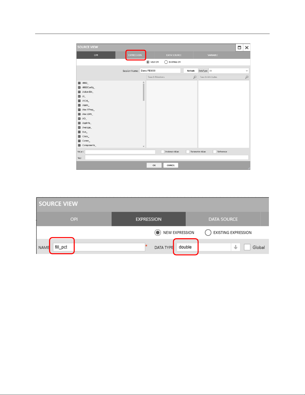
The Source View window opens. Select the Expression tab.
D301884X012
October 2019
An expression is a program written in C# to return (output) some value, like a function
block. This expression will return the fill percentage of the separator, so name it
and select
We need to use the value of the liquid level, so select the OPI tab. The OPI screen displays.
double as the Data Type.
fill_pct
FBxVue 79
Page 84
Emerson FB3000 Separator Configuration Guide
D301884X012
October 2019
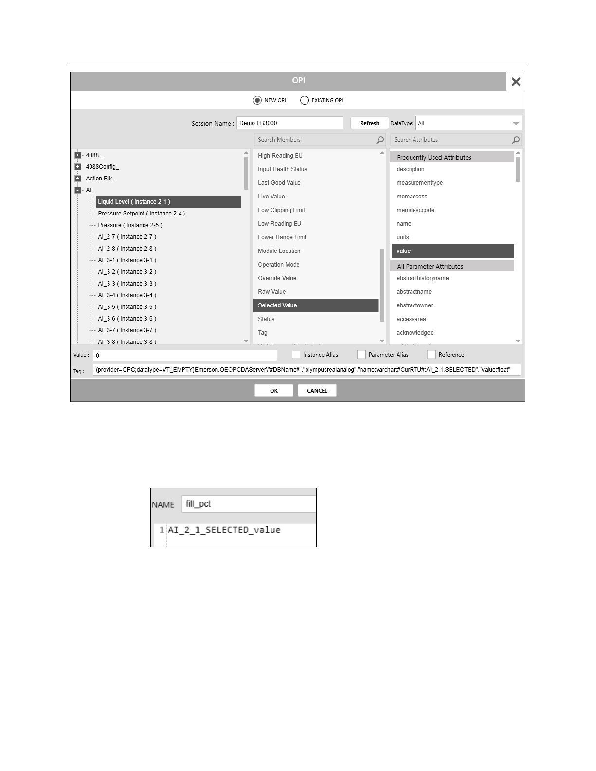
In the OPI window (Point Picker) that opens, select AI_ > Liquid Level (Instance 2-1) >
Selected Value > value. Note that you must select the Value attribute for the Selected
Value point. Click
FBXVue inserts the OPI into the expression, using a different syntax than the tag you would
copy off an FBxConnect point picker would have:
Using the OPI, enter the following expression:
OK.
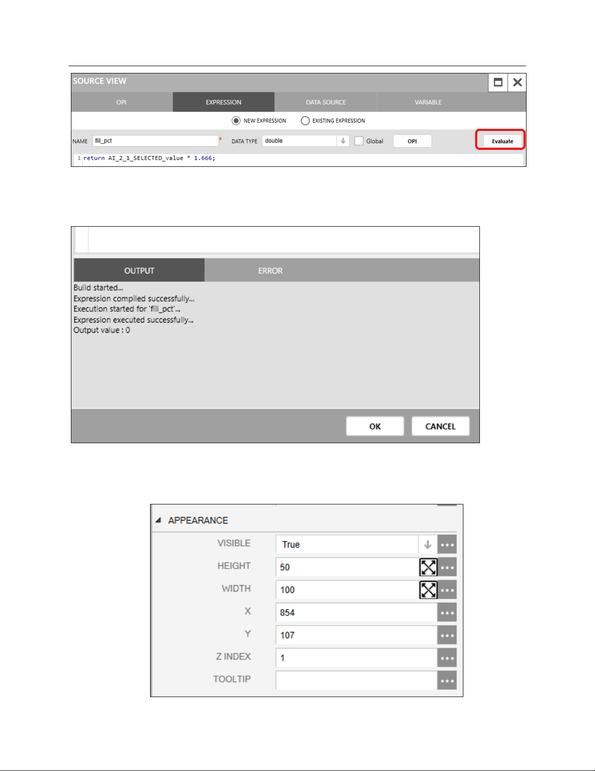
return AI_2_1_SELECTED_value * 1.666;
(the 1.666 comes from multiplying by 100% and then dividing by 60 inches). Click
Evaluate.
80 FBxVue
Page 85
Emerson FB3000 Separator Configuration Guide
D301884X012
October 2019
A message window at the bottom of the Source View screen (much like the message
window on the bottom of the FBxDesigner screen) alerts you to any errors or warnings If
there are no errors, the message evaluates the code and tells you what was returned.
Click OK.
In the Properties window, enter 1 as the Z Index for the rectangle. This allows the rectangle
to be visible on top of the separator image.
FBxVue 81
Page 86
Emerson FB3000 Separator Configuration Guide
D301884X012
October 2019
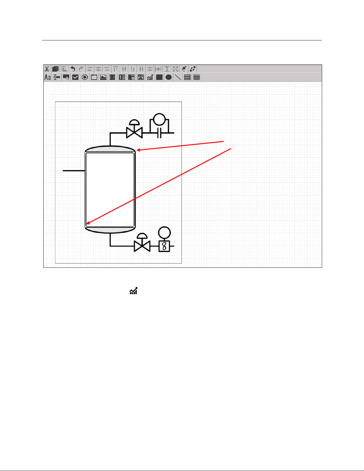
Now, click-and-drag the corners of the rectangle so that it covers the rectangle of the
separator tank.
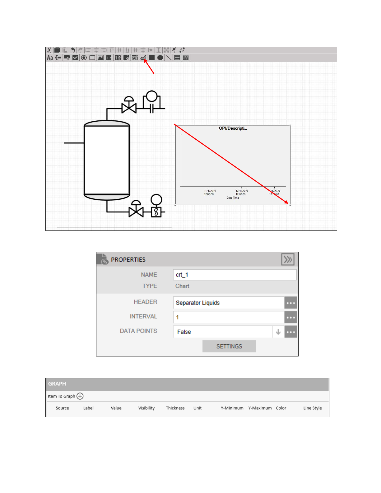
Now let’s add a chart to show the trend of the liquid level and the liquid turbine flow rate.
Click the Chart ) button and click-and-drag an area in the center of the display, to the
right of the separator tank, as shown below:
82 FBxVue
Page 87
Emerson FB3000 Separator Configuration Guide
D301884X012
October 2019
With the Chart selected, enter Separator Liquids as the header and enter 1 as the interval:
Click Settings to set-up the chart. The Graph screen displays.
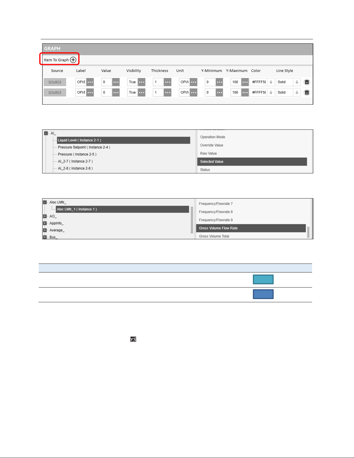
In the Graph screen, click the Item to Graph (+) button twice to add two variables.
FBxVue 83
Page 88
Emerson FB3000 Separator Configuration Guide
Source
Label
Value
Visibility
Thickness
Unit
Y-Min
Y-Max
Color
Line Style
D301884X012
October 2019
Click Source for the first variable and then select AI_ >Liquid Level (Instance 2-1) and
Selected Value.
Click Source for the second variable and select Aloc LMtr_ > Aloc LMtr_1 (Instance 1) >
Gross Volume Flow Rate
- Liquid
- Liquid
Level
Flow Rate
Enter the following values for the rest of the properties:
-
-
True 1 In 0 60
True 1 bbl/d 0 4000
Click OK on the bottom of the Graph window.
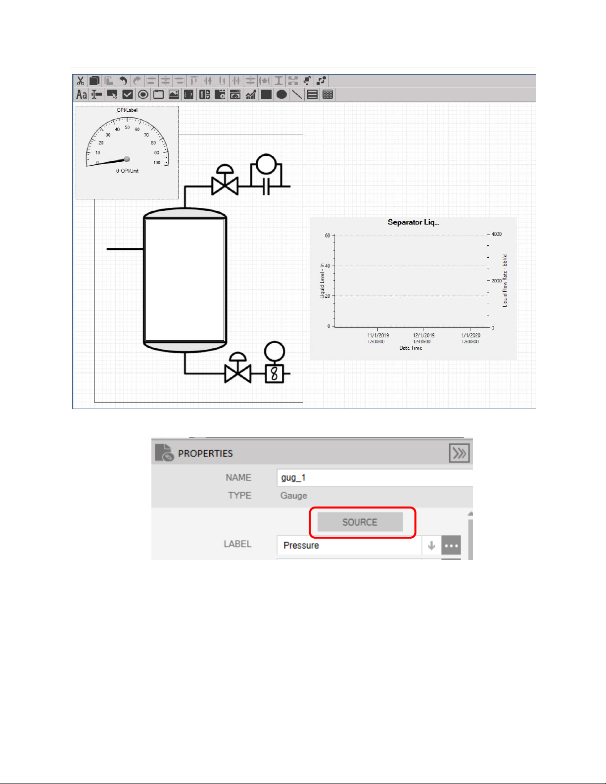
Now let’s add a pressure gauge to monitor the pressure.
Click the Gauge ( ) button and click-and-drag the top left corner as shown below.
Solid
Dash
84 FBxVue
Page 89
Emerson FB3000 Separator Configuration Guide
D301884X012
October 2019
With the Gauge selected, click on Source in the Properties window.
In the Point Picker, select AI_ > Pressure > Selected Value.
Notice that this selection completes many fields immediately:
FBxVue 85
Page 90

Emerson FB3000 Separator Configuration Guide
D301884X012
October 2019
However, these system-provided values are not always the most useful properties. Enter
Pressure as the label (otherwise the label would be “Selected Value”). Enter psi(g) as the
unit, and enter
0 as the minimum and 30 as the maximum. The result should be:
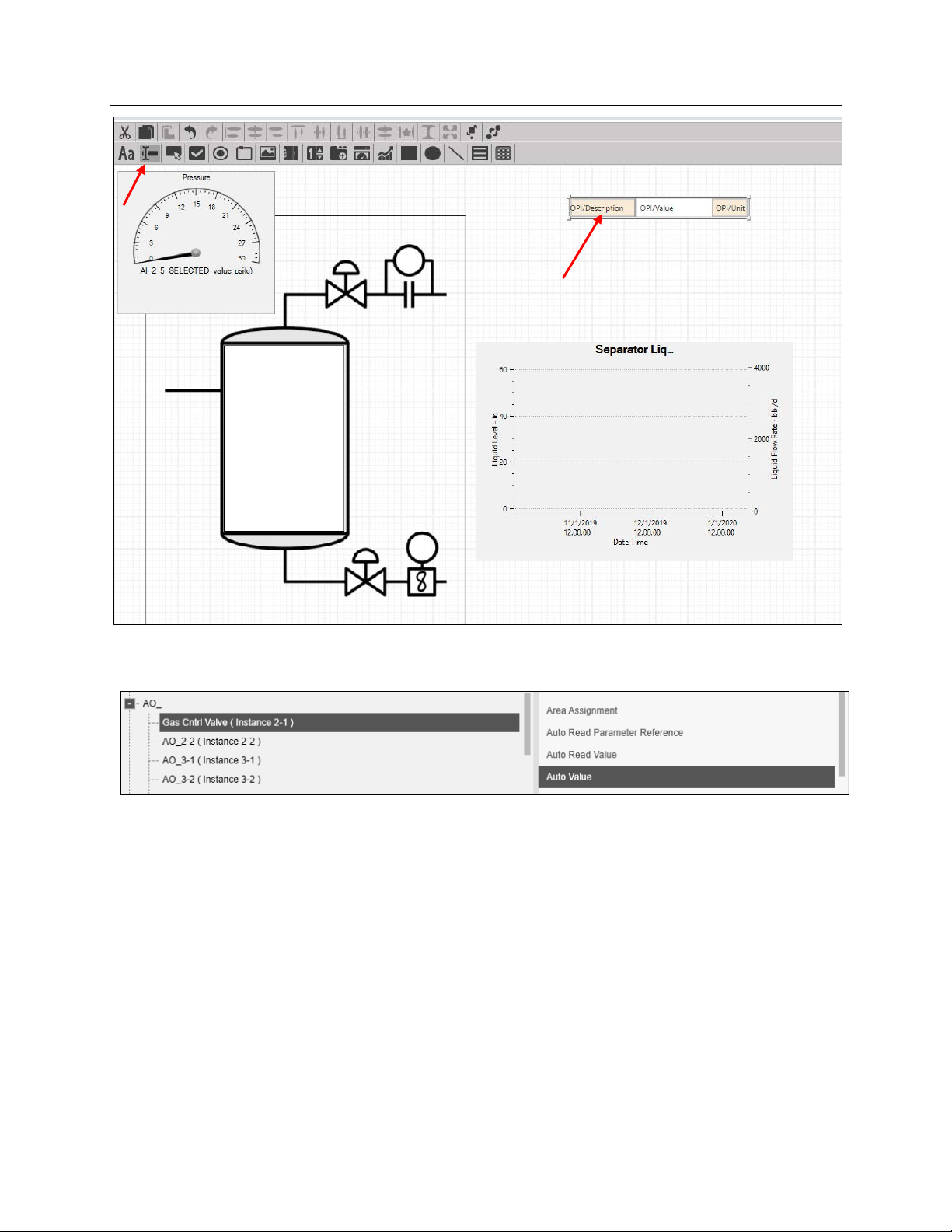
Now let’s add the Valve and Meter info to the screen.
Click the TextBox ( ) button and then click an empty space in the canvas:
86 FBxVue
Page 91
Emerson FB3000 Separator Configuration Guide
D301884X012
October 2019
In the Properties window, click on Source and select the Auto Value of the Gas Control
Valve.
Enter Valve Status as the Title and %Open as the unit.
Click-and-drag the TextBox to be near the Gas Control Valve on top of the separator.
FBxVue 87
Page 92

Emerson FB3000 Separator Configuration Guide
Source
Title
Location
D301884X012
October 2019
Create four more TextBoxes, with the following properties:
DP_Mtr > DP Mtr_1 > Cor. Vol. Flow Rate
DO > Lvl_Cntrl_Valve > Auto Value Valve Status (On =
Aloc LMtr_ > Aloc LMtr_1 > Gross Vol Flow Rate Liquid Meter Near Meter on Bottom
AI_ > Pressure Setpoint > Override Value Pressure Setpoint Under Pressure Gauge on
Make sure to preview your display as you move and adjust the location of objects. You can
also click-and-drag parts of the text boxes to make the title or value sections bigger or
smaller. When done, the display should look similar to this when previewing it:
Gas Meter Near Meter on Top
Near Valve on Bottom
Open)
Top left
88 FBxVue
Page 93

Emerson FB3000 Separator Configuration Guide
D301884X012
October 2019
Note that the Liquid Level does not change until after we download the FBxDesigner
project.
When you are done, click Save As in the FBxVue top menu.
You can either save the display on your PC as an .xml file or save it directly to the device as
a standalone display. For this demo, we will download it to the PC so that we can install it
with FBxDesigner.
Click Browse.
FBxVue 89
Page 94

Emerson FB3000 Separator Configuration Guide
D301884X012
October 2019
Enter Separator Display as the file name and click Save; place the file in a folder you can
find later.
90 FBxVue
Page 95

Emerson FB3000 Separator Configuration Guide
Chapter 6. Applications
Now that you have a project and display ready, you can download them to the RTU. First,
you need package them together as an application.
In FBxConnect, select the Applications tab and click Management:
The Application Management screen displays:
D301884X012
October 2019
Notice that the screen displays 8 available slots for applications.
Select slot 1 and click Add FBxDesigner project. The Add FBxDesigner project to Solution
screen displays.
Applications 91
Page 96
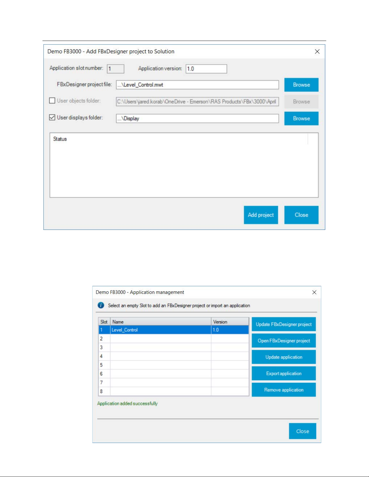
Emerson FB3000 Separator Configuration Guide
D301884X012
October 2019
Click Browse and find the Level_Control.mwt file from the saved FBxDesigner project.
Select the option for User displays folder and click Browse to find the folder in which you
saved the Separator Display.xml file. Note that you have multiple displays in the folder that
are all added.
Click Add project and then Close. The system downloads the files to the FB3000.
92 Applications
Page 97
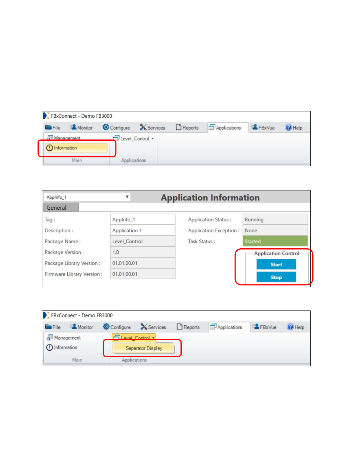
Emerson FB3000 Separator Configuration Guide
D301884X012
October 2019
If you included the source code, you can click Open FBxDesigner to view the project from
the RTU. You can now export the application as a .zap file (which is the recommended way
of distributing applications).
Click Close.
Select the Applications tab and click Information. The Application Information screen
displays.
The Information page shows information about the Application selected. Note the Start
and
Stop buttons, which enable you to start and stop the application task.
Note that the Applications tab now has a Level_Control button. Click it to select the
Separator Display menu option.
The Separator display opens, and you can see the project control working as the level goes
up and down as the Liquid Control Valve opens and closes. You can change the Pressure
Setpoint from this page and see how the Gas Control Valve reacts.
Applications 93
Page 98
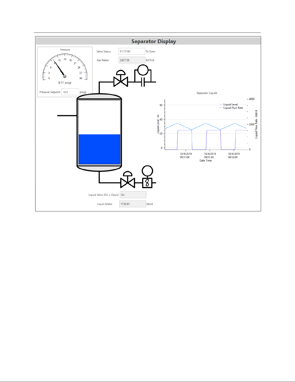
Emerson FB3000 Separator Configuration Guide
D301884X012
October 2019
94 Applications
Page 99

Emerson FB3000 Separator Demo Guide
D301884X012
October 2019
Configuring the FG-400 95
Page 100

Emerson FB3000 Separator Configuration Guide
For customer service and technical support,
Global Headquarters,
North America, and Latin America:
end-user.
Europe:
Middle East/Africa:
Asia-Pacific:
T +65 6777 8211| F +65 6777 0947
D301884X012
October 2019
visit www.Emerson.com/SupportNet
Emerson Automation Solutions
Remote Automation Solutions
6005 Rogerdale Road
Houston, TX 77072 U.S.A.
T +1 281 879 2699 | F +1 281 988 4445
www.Emerson.com/RemoteAutomation
Emerson Automation Solutions
Remote Automation Solutions
Unit 1, Waterfront Business Park
Dudley Road, Brierley Hill
Dudley DY5 1LX UK
T +44 1384 487200 | F +44 1384 487258
Emerson Automation Solutions
Remote Automation Solutions
Emerson FZE
P.O. Box 17033
Jebel Ali Free Zone – South 2
Dubai U.A.E.
T +971 4 8118100 | F +971 4 8865465
Emerson Automation Solutions
Remote Automation Solutions
1 Pandan Crescent
Singapore 128461
© 2019 Remote Automation Solutions, a business unit of Emerson Automation Solutions. All
rights reserved.
This publication is for informational purposes only. While every effort has been made to ensure
accuracy, this publication shall not be read to include any warranty or guarantee, express or
implied, including as regards the products or services described or their use or applicability.
Remote Automation Solutions (RAS) reserves the right to modify or improve the designs or
specifications of its products at any time without notice. All sales are governed by RAS terms
and conditions which are available upon request. RAS accepts no responsibility for proper
selection, use or maintenance of any product, which remains solely with the purchaser and/or
Remote Automation Solutions
Loading...