

Remote Automation Solutions Emerson FB2100 Flow Computer Safe Use Instructions Manuals & Guides
Page 1

Safe Use Instructions:
UK
DE
FR
PT
SC
IT
NL
SP
Emerson FB2100 Flow Computer
Safe Use Instructions – Emerson FB2100
Part D301770X012
June 2021
Safe Use Instructions
Anleitung zur sicheren Verwendung
Consignes de sécurité
Instruções para uso seguro
安全使用说明
Istruzioni per l’uso sicuro
Instructies voor veilig gebruik
Instrucciones para un uso seguro
Remote Automation Solutions
Page 2

Safe Use Instructions – Emerson FB2100
Part D301770X012
June 2021
Page 3

Safe Use Instructions – Emerson FB2100 Flow Computer
Replacement Part
Kit Number
Field Replacement
Guide document
number
8-Channel Expansion
6-Channel Expansion
HMI Module Display
399379-01-0,
400210010-KIT,
CPU Enclosure and
621673-01-0,
399291-01-0,
399394-00-0
395828-01-0
395620-03-1
Emerson FB2100 Flow Computer
Specific Conditions of Use
Use equipment in an area of not more than pollution
degree 2.
Make provisions to ensure, in the event of transient
disturbances, that the rated voltage does not exceed
140% of the peak rated voltage.
Lead acid battery and solar power options are not for
use in ATEX applications.
Impact tests on the display were conducted based on
Group II values for the low risk of mechanical danger,
in accordance with Table 13 of both EN 600790:2012+A11:2013 and IEC 60079‐0 6
Figure 1. Emerson FB2100 Label
(Non-sparking with Integral Sensor)
Use this safe use instructions (SUI) document with the
Emerson FB2100 Flow Computer Instruction Manual (part
D301783X012). For full cautions and descriptions of
installation and troubleshooting procedures, refer to this
manual. If you require training for this product, contact
your local sales office.
The Emerson FB2100 Flow Computer (or “FB2100”) with
ATEX approval may be ordered with any of the optional
communications or I/O modules listed in the product data
sheet Emerson FB2100 Flow Computer (part
D301791X012).
f
impact is low.
In Zone 2 installations, ensure that the flow computer
is installed and used to prevent the danger of
electrostatic charges.
The FB2100 enclosure requires a tool to open. Refer to
the Physical Security section in Chapter 1 of the
Emerson FB2100 Flow Computer Instruction Manual
(part D301783X012) for further details.
Refer to Table 1 for replacement parts.
Part D301770X012
June 2021
th
Edition. Install
low computers with displays in areas where the risk of
Table 1. Replacement Parts
Figure 2. Emerson FB2100 Label
(Non-sparking without Integral Sensor)
Statement of Conformity
Hereby, Remote Automation Solutions declares that the
Emerson FB2100 Flow Computers are in compliance with
the essential requirements and other relevant provisions
of European Directives 2014/30/EU (EMC), and
2014/34/EU (ATEX).
I/O Board
I/O Board
Assembly
I/O Termination
Board
Electronics
Sensor Variable Kit Number D301843X012
Door Accessories
Relay
Coin Cell Battery
400217010-KIT D301804X012
400215010-KIT D301803X012
D301822X012
621627011-KIT,
399380-01-0,
621627020-KIT
D301805X012
358807010-KIT
D301803X012
621674-01-0,
621675-01-0,
621676-01-0,
621678-01-0,
400209010-KIT,
399260-01-0,
399264-01-0,
400211010-KIT
D301825X012
399267-01-0,
399266-01-0,
621661010-KIT,
D301847X012
D301855X012
Remote Automation Solutions
Page 4

Safe Use Instructions – Emerson FB2100 Flow Computer
Specifications
POWER
ENCLOSURE
Housing:
ENVIRONMENTAL
Operating Temperature:
Storage Temp.:
Operating Humidity:
WEIGHT
APPROVALS
Evaluated to the following European Standards (EMC):
Immunity
Evaluated to the following Approval Standards:
Evaluated to the following Standards (IEC):
Product Markings for Hazardous Locations:
Part D301770X012
June 2021
Operating Range: 10.5 Vdc to 30 Vdc (10W max power)
Powder-coat aluminum, with lockable door.
Compression-molded fiberglass, with lockable door
DANGER
When installing units in a hazardous area, make sure all
installation components selected are labeled for use in
such areas. Installation and maintenance must be
performed only when the area is known to be nonhazardous. Installation or maintenance in a hazardous
area could result in personal injury or property damage.
Always turn off the power to the FB2100 before you
attempt any type of wiring. Wiring of powered
equipment could result in personal injury or property
damage.
Non-sparking (Ex nA): –25°C to +55°C.
–40°C to +85°C.
5-95% non-condensing per IEC
60068-2-3.
6.94 kg (15.3 lbs) (fiberglass enclosure)
10.75 kg (23.7 lbs) (aluminum enclosure)
EN 61326-2-3:2013 (Immunity)
EN 61000-4-2 (Electro Static Discharge)
EN 61000-4-3 (Radiated Immunity)
EN 61000-4-4 (Fast Transients)
EN 61000-4-5 (Surges)
EN 61000-4-6 (Conducted RF)
EN 61000-4-8 (Power Frequency Magnetic Field)
EN 61000-4-17 (Voltage Ripple)
EN 61000-4-29 (Voltage Dips and Interrupts)
Directive 2014/34/EU
EN 60079-0:2012+A11:2013
EN 60079-15:2010
IEC 60079-0 (2011), 6
IEC 60079-15 (2010), 4
Ex nA IIC T4 Gc (–25°C ≤ T
th
Edition
th
Edition
amb
≤ +55°C),
To avoid circuit damage when working
inside the unit, use appropriate electrostatic discharge
precautions, such as wearing a grounded wrist strap.
Check the input power polarity before connecting power
to the FB2100. Wiring of powered equipment could result
in personal injury or property damage.
The following tools are required for installation,
maintenance, and troubleshooting:
Personal computer running Microsoft
Professional or Windows 8.1 Pro, or Windows 10 Pro
®
Windows® 7
and Emerson Field Tools configuration software
(providing FBxConnect™).
#1 and #2 Phillips (cross-head) screwdriver.
3 mm (1/8-inch) flat-head screwdriver.
Unpacking
You receive the FB2100 in a box. Remove it from the box.
Examine the packing list carefully to ensure you have all
components.
Installation
1. Find a suitable location for the FB2100. When
selecting an installation site, be sure to check all
clearances. The FB2100 housing is designed to
withstand a variety of inclement conditions. The
optional LCD should be visible and accessible for the
on-site operator.
II 3 G
Cert. No. DEMKO 16 ATEX 1579X
2 www.Emerson.com/RemoteAutomation
Page 5

Safe Use Instructions – Emerson FB2100 Flow Computer
Part D301770X012
June 2021
Figure 3. Front View of the FB2100 (Aluminum Enclosure)
(with optional integral MVS sensor)
Figure 5. Front View of the FB2100 (Fiberglass Enclosure)
(with optional integral MVS sensor)
Figure 4. Side View of the FB2100 (Aluminum Enclosure)
(with optional integral MVS sensor)
www.Emerson.com/RemoteAutomation 3
Figure 6. Side View of the FB2100 (Fiberglass Enclosure)
(with optional integral MVS sensor)
Page 6

Safe Use Instructions – Emerson FB2100 Flow Computer
Part D301770X012
June 2021
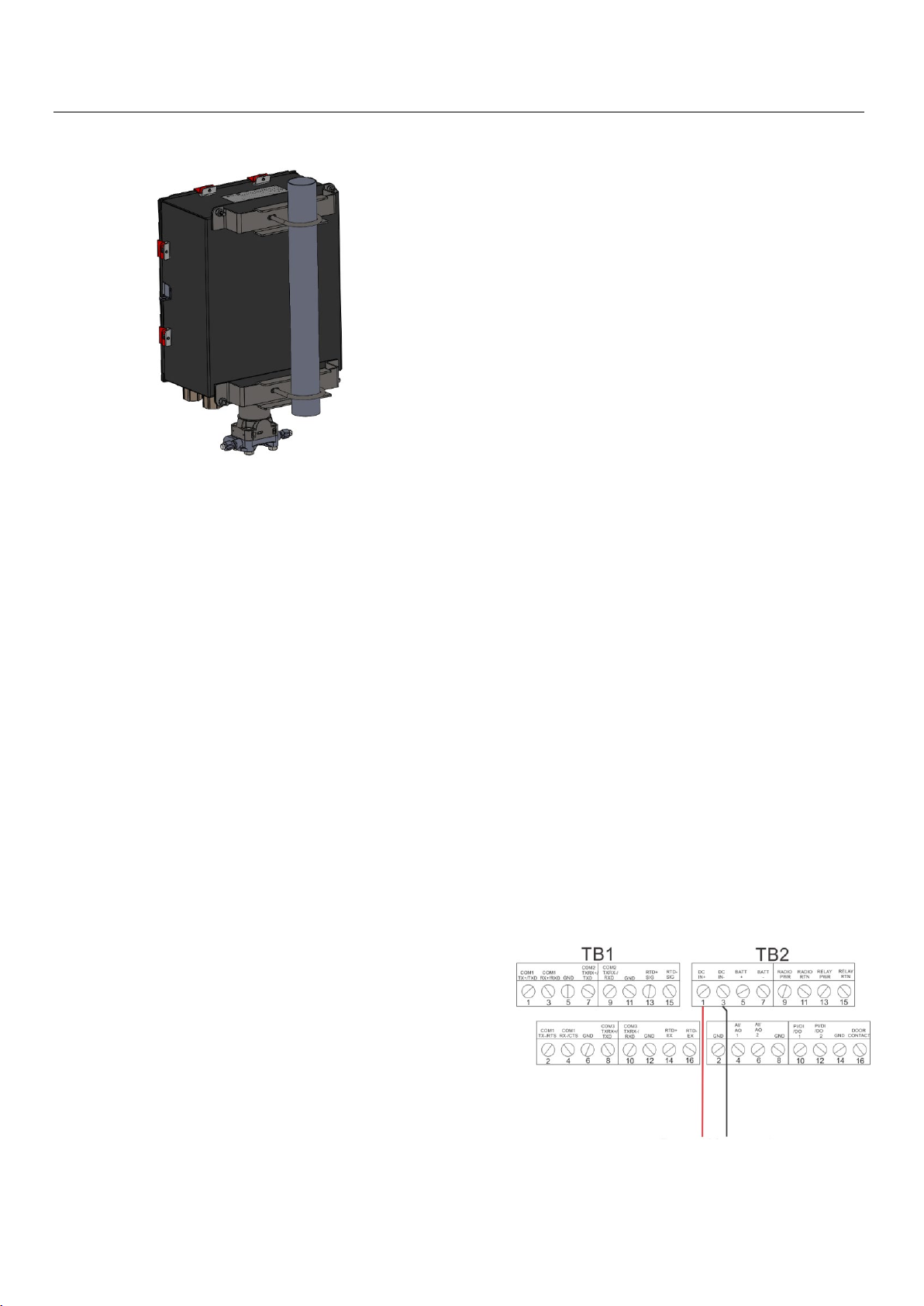
2. The FB2100 mounts on a two-inch pipe or pole. See
Figure 7.
Figure 7. FB2100 (Aluminum Enclosure) on Pipe Mount
Grounding
Open the front door of the FB2100 as detailed in either
Chapter 2 of the Emerson FB2100 Flow Computer
Instruction Manual (part D301783X012) or in the
Emerson FB2100 Flow Computer Quick Start Guide (part
D301787X012).
If your company has no specific grounding
requirements, install the FB2100 as a “floating”
(unconnected to ground) system using the ground lug
and routing the ground wire through one of the conduit
fittings. Otherwise, follow your company’s specific
grounding practices. However, if you are making a
connection between a grounded device and an EIA-232
(RS-232) port,
If you must ground the equipment, observe the
following guidelines:
When the equipment uses a DC voltage source,
the grounding system must terminate at the
service disconnect. All equipment grounding
conductors–including wire or conduit carrying the
power supply conductors–must provide an
uninterrupted electrical path to the service
disconnect.
ground the FB2100’s power supply.
The grounding installation method for the FB2100
depends on whether the pipeline has cathodic
protection. On pipelines with cathodic protection,
electrically isolate the FB2100 from the pipeline. All
earth grounds must have an earth-to-ground rod or
grid impedance of 25 ohms or less, as measured with
a ground system tester.
Wiring to Power
Wire the FB2100 through the conduit fittings on the
bottom of the housing. The terminal blocks accept 2mm
in diameter/3mm
to the removable block compression terminals:
Bare the end (6mm maximum) of the wire.
Insert the bared end of the wire into the clamp
beneath the termination screw.
Tighten the screw.
Expose a minimum of bare wire to prevent short circuits.
Allow some slack when making connections to prevent
strain.
Connect the power wiring. Review the power wiring
descriptions in Chapter 2 of the Emerson FB2100 Flow
Computer Instruction Manual (part D301783X012).
Verify the hook-up polarity is correct.
To make DC power supply connections:
Remove the terminal block connector from the
socket.
Insert each bare wire end into its appropriate
connector and secure the wire (see Figure 8).
Plug the terminal block connector back into the
socket.
2
or smaller wiring. To connect the wire
Improper grounding or poor grounding practices
can often cause problems, such as introducing
ground loops into the system. Properly grounding
the FB2100 helps to reduce the effects of electrical
Figure 8. Wiring to DC Power Supply
noise on the unit’s operation and protects against
lightning. Install a surge protection device at the
service disconnect on DC voltage source systems
to protect the installed equipment against
Refer to the Emerson FB2100 Flow Computer Quick Start
Guide (part D301787X012) for detailed instructions on
connecting the battery.
lightning and power surges.
Ensure that the flow computer’s ground is
separate from the cathodic protection ground.
4 www.Emerson.com/RemoteAutomation
Page 7

Safe Use Instructions – Emerson FB2100 Flow Computer
Part D301770X012
June 2021
Wiring to Communications & I/O
Connect the wiring to the terminal blocks on the I/O and
communications modules. Refer to either Section 2.8 in
Chapter 2 of the Emerson FB2100 Flow Computer
Instruction Manual (part D301783X012) or the Emerson
FB2100 Flow Computer Quick Start Guide (part
D301787X012) for wiring schematics and
explanations.
Once you have wired the communications and I/O,
close and secure the cover of FB2100.
Powering Up the FB2100
DANGER
Do not attempt to connect power or disconnect power
from the unit in a hazardous area. Ensure the area is
non-hazardous. Failure to do so could result in an
explosion.
1. To start up the FB2100, apply power.
When you turn power on, the backlight on the HMI
module lights for about 5 seconds, then turns off.
During this time the database begins to initialize.
After about 45 seconds the backlight on the HMI
turns on again and starts to display live data.
Periodically inspect the wiring for signs of
deterioration.
Returning the FB2100
If you are experiencing problems that appear to be
hardware-related, verify the wiring. If you still experience
problems, contact your local sales office for return
authorization. To return the device:
1. Back up all configuration and data before removing
the device from process. Then remove power from
the device and remove all external wiring.
2. Uninstall the device.
3. Place the device into a box safe for shipping or
storage.
Configuring the FB2100
You must install Emerson’s Field Tools configuration
software (which includes FBxConnect™) on your PC to
configure the FB2100 for use. Refer to the Emerson
FB2100 Flow Computer Quick Start Guide (part
D301787X012) for instructions on installing and using
this software.
Resetting the FB2100
If you are experiencing problems that appear to be
software related, try resetting the FB2100. Refer to the
Service and Troubleshooting chapter in the Emerson
FB2100 Flow Computer Instruction Manual (part
D301783X012) for specific instructions.
Note: You lose all configuration and log data with a
reset. If possible, make a backup of
configuration and log data
any type of reset.
before attempting
Replacing Parts in the FB2100
Refer to Table 1 for a list of user-serviceable parts and their
respective Field Replacement Guides.
www.Emerson.com/RemoteAutomation 5
Page 8

Safe Use Instructions – Emerson FB2100 Flow Computer
Global Headquarters,
North America, and Latin America:
end-user.
Europe:
Middle East/Africa:
Asia-Pacific:
T +65 6777 8211| F +65 6777 0947
Part D301770X012
June 2021
For customer service and technical support,
visit www.Emerson.com/SupportNet.
Emerson Process Management
Remote Automation Solutions
6005 Rogerdale Road
Houston, TX 77072 U.S.A.
T +1 281 879 2699 | F +1 281 988 4445
www.Emerson.com/RemoteAutomation
Emerson Process Management
Remote Automation Solutions
Unit 1, Waterfront Business Park
Dudley Road, Brierley Hill
Dudley DY5 1LX UK
T +44 1384 487200
Emerson Process Management
Remote Automation Solutions
Emerson FZE
P.O. Box 17033
Jebel Ali Free Zone – South 2
Dubai U.A.E.
T +971 4 8118100 | F +971 4 8865465
Emerson Process Management
Remote Automation Solutions
1 Pandan Crescent
Singapore 128461
© 2017-2021 Remote Automation Solutions, a business unit of Emerson Process
Management. All rights reserved.
This publication is for informational purposes only. While every effort has been made to ensure
accuracy, this publication shall not be read to include any warranty or guarantee, express or
implied, including as regards the products or services described or their use or applicability.
Remote Automation Solutions (RAS) reserves the right to modify or improve the designs or
specifications of its products at any time without notice. All sales are governed by RAS terms
and conditions which are available upon request. RAS accepts no responsibility for proper
selection, use or maintenance of any product, which remains solely with the purchaser and/or
Remote Automation Solutions
Page 9

Anleitung zur sicheren Verwendung – Emerson FB2100
Ersatzteil
Kit Number
FeldersatzanleitungDokumentnummer
8-Kanal-
400217010-KIT
D301804X012
Platine
399379-01-0,
400210010-KIT,
CPU-Gehäuse und -
621673-01-0,
D301803X012
399291-01-0,
399394-00-0
395828-01-0
395620-03-1
Emerson FB2100 Flow Computer
Treffen Sie Vorbereitungen, damit die Nennspannung
▪
im Falle einer kurzzeitigen Störung 140 % der
Spitzennennspannung nicht überschreitet.
Bleisäurebatterien und Solarenergieoptionen sind
▪
nicht für ATEX-Anwendungen bestimmt.
In Übereinstimmung mit Tabelle 13 aus
▪
N 60079-0:2012+A11:2013 und IEC 60079‐ 0, 6.
E
Ausgabe, wurden basierend auf Gruppe-II-Werten
für geringes Risiko mechanischer Gefährdung
Schlagprüfungen auf dem Display durchgeführt.
Bringen Sie Durchflusscomputer so an, dass die
Displays einem geringen Schlagrisiko ausgesetzt sind.
Stellen Sie bei Zone-2-Installationen sicher, dass der
▪
bbildung 1. Emerson FB2100 Typenschild
A
(funkenfrei mit integriertem Sensor)
Diese Anleitung zur sicheren Verwendung ergänzt die
Betriebsanleitung für den Emerson FB2100 Flow Computer
(Dok.-Nr. D301783X012). In diesem Handbuch finden Sie
ausführliche Warnungen, eine Installationsanleitung und
Verfahren zur Problemlösung. Sollten Sie für dieses
Produkt eine Schulung benötigen, wenden Sie sich bitte
an Ihr örtliches Vertriebsbüro.
Der Emerson FB2100 Flow Computer (oder „FB2100“) mit
ATEX-Zulassung kann mit einem der optionalen
Kommunikations- oder E/A-Module bestellt werden, die
auf dem Produktdatenblatt des Emerson FB2100 Flow
Computers (Dok.-Nr. D301791X012) aufgeführt sind.
Durchflusscomputer installiert ist und verwendet wird,
um die Gefahr elektrostatischer Aufladung zu
vermeiden.
Das FB2100-Gehäuse kann muss mit einem Werkzeug
▪
g
de
Bedienungsanleitung für den EmersonDurchflusscomputer FB2100 (Teil D301783X012)
entnehmen.
Für Ersatzteile siehe Tabelle 1.
▪
Erweiterungs-E/APlatine
6-KanalErweiterungs-E/A-
Dok.-Nr. D301770X012
Juni 2021
eöffnet werden. Weitere Informationen können Si
m Abschnitt „Physische Sicherheit“ in Kapitel 1 der
elle 1. Ersatzteile
Tab
400215010-KIT D301803X012
e
Konformitätserklärung
Remote Automation Solutions erklärt hiermit, dass die
Emerson FB2100 Flow Computer den grundlegenden
Anforderungen und anderen relevanten Vorschriften der
EU-Richtlinien 2014/30/EU (EMV) und 2014/34/EU (ATEX)
entsprechen.
Spezielle Voraussetzungen für die Verwendung
Bringen Sie das Gerät in einem Bereich mit einem
▪
erschmutzungsgrad von höchstens 2 zum Einsatz.
V
Abbildung 2. Emerson FB2100 Typenschild
(funkenfrei mit integriertem Sensor)
HMI-ModulBedieninterface
E/AAnschlussplatine
Elektronik
Sensor Variablensatznummer D301843X012
Türzubehör
Relais
Knopfzellenbatterie
621627011-KIT,
399380-01-0,
621627020-KIT
358807010-KIT
621674-01-0,
621675-01-0,
621676-01-0,
621678-01-0,
400209010-KIT,
399260-01-0,
399264-01-0,
400211010-KIT
399267-01-0,
399266-01-0,
621661010-KIT,
D301822X012
D301805X012
D301825X012
D301847X012
D301855X012
Remote Automation Solutions
Page 10

Anleitung zur sicheren Verwendung – Emerson FB2100
Spezifikationen
SPANNUNGSVERSORGUNG
GEHÄUSE
Gehäuse:
UMGEBUNGSBEDINGUNGEN
Betriebstemperatur:
Lagertemperatur:
Betriebsluftfeuchtigkeit:
GEWICHT
ZULASSUNGEN
Bewertet gemäß folgenden europäischen
Normen(EMC):
Immunität
Bewertet gemäß den folgenden Zulassungsstandards:
Bewertet gemäß den folgenden Standards (IEC):
Produktkennzeichnungen für Gefahrenbereiche:
Dok.-Nr. D301770X012
Juni 2021
Betriebsbereich: 10,5 VDC bis 30 VDC (10 W max.
Strom)
Pulverbeschichtetes Aluminium, mit verriegelbarer Tür.
Druckgespritztes Fiberglas, mit verriegelbarer Tür
funkenfrei (Ex nA): –25 °C bis +55 °C.
–40 °C bis +85 °C.
5 - 95 % nicht kondensierend
gemäß IEC 60068-2-3.
6,94 kg (15.3 lbs) (Fiberglasgehäuse)
10,75 kg (23.7 lbs) (Aluminiumgehäuse)
EN 61326-1:2013 (Emissionen)
EN 61000-4-2 (elektrostatische Entladung)
EN 61000-4-3 (Störstrahlungsimmunität)
EN 61000-4-4 (Schnelle Transienten)
EN 61000-4-5 (Stoßspannungen)
EN 61000-4-6 (Geleitete RF)
EN 61000-4-8 (Magnetfeld bei Nennfrequenz)
EN 61000-4-17 (Spannungswelligkeit)
EN 61000-4-29 (Spannungseinbrüche und
Unterbrechungen)
Richtlinie 2014/34/EU
EN 60079-0:2012+A11:2013
EN 60079-15:2010
IEC 60079-0 (2011), 6
IEC 60079-15 (2010), 4
Ex d IIC T4 Gc (–25 °C ≤ T
II 3 G
Zert. Nr. DEMKO 16 ATEX 1579X
.
Ausgabe
.
Ausgabe
≤ +55 °C)
amb
GEFAHR
Wenn Geräte in einem explosionsgefährdeten Bereich
installiert werden, muss darauf geachtet werden, dass
alle ausgewählten Installationskomponenten für den
Einsatz in solchen Bereichen zugelassen sind.
Installations- und Wartungsarbeiten dürfen nur dann
durchgeführt werden, wenn der Arbeitsbereich nicht in
einem Ex-Bereich liegt. Installations- und
Wartungsarbeiten in einem Ex-Bereich können zu
Personen- und/oder Sachschäden führen.
Vor der Verkabelung des Gerätes stets die
Spannungsversorgung vom FB2100 trennen. Die
Verkabelung eines mit Spannung versorgten Gerätes
kann zu Personen- und/oder Sachschäden führen.
Um elektrische Schäden bei Arbeiten im Geräteinneren
zu vermeiden, müssen die erforderlichen Vor-sichts-maßnah-men zur Vermeidung elektrostatischer Entladungen
eingehalten werden, zum Beispiel durch das Tragen eines
Antistatikbands.
Vor dem Einschalten der Spannungsversorgung des
FB2100 die Polarität des Eingangsstroms prüfen. Die
Verkabelung eines mit Spannung versorgten Gerätes kann
zu Personen- und/oder Sachschäden führen.
Für Installation, Wartung sowie Störungsanalyse und beseitigung sind die folgenden Hilfsmittel bzw.
Werkzeuge erforderlich:
®
PC mit Microsoft
8.1 Pro oder Windows 10 Pro und der Emerson Field
Tools Konfigurationssoftware (mit FBxConnect™)
Kreuzschlitzschraubendreher Nr. 1 und Nr. 2.
Schlitzschraubendreher 3 mm (1/8 in.).
Auspacken
Der FB2100 wird in einem Karton geliefert. Nehmen Sie
das Gerät aus dem Karton. Prüfen Sie die Packliste
sorgfältig, um sicherzustellen, dass Sie alle Komponenten
zur Hand haben.
Einbau
1. Einen geeigneten Standort für den FB2100 wählen.
Bei der Auswahl eines Einbauortes alle Abstände
prüfen. Das Gehäuse des FB2100 widersteht einer
Reihe von rauen Bedingungen. Die optionale LCDAnzeige sollte für den Bediener vor Ort sichtbar und
zugänglich sein.
Windows® 7 Professional, Windows
2 www.Emerson.com/RemoteAutomation
Page 11

Anleitung zur sicheren Verwendung – Emerson FB2100
Dok.-Nr. D301770X012
Juni 2021
Abbildung 3. Frontansicht des FB2100 (Aluminiumgehäuse)
(mit optionalem integralen MVS-Sensor)
Abbildung 5. Frontansicht des FB2100 (Fiberglasgehäuse)
(mit optionalem integralen MVS-Sensor)
Abbildung 4. Seitenansicht des FB2100 (Aluminiumgehäuse)
(mit optionalem integralen MVS-Sensor)
Abbildung 6. Seitenansicht des FB2100 (Fiberglasgehäuse)
(mit optionalem integralen MVS-Sensor)
www.Emerson.com/RemoteAutomation 3
Page 12

Anleitung zur sicheren Verwendung – Emerson FB2100
Dok.-Nr. D301770X012
Juni 2021
2. Der FB2100 wird an einer Leitung oder einem Pfosten
mit einem Durchmesser von 2 Zoll angebracht. Siehe
Abbildung 7.
Abbildung 7. FB2100 (Aluminiumgehäuse) am Rohr montiert
Erdung
Die vordere Tür des FB2100 gemäß entweder Kapitel 2
der Bedienungsanleitung für den Emerson FB2100 Flow
Computer (Dok.-Nr. D301783X012) oder der
Kurzanleitung für den Emerson FB2100 Flow Computer
(Dok.-Nr. D301787X012) entfernen.
Wenn es in Ihrem Unternehmen keine speziellen
Erdungsvorschriften gibt, installieren Sie den FB2100
als ein „potentialfreies“ (ungeerdetes) System mittels
des Erdungsanschlusses und führen Sie das
Erdungskabel durch eine der Kabelverschraubungen.
Andernfalls die speziellen Erdungsverfahren Ihres
Unternehmens beachten. Wenn Sie eine Verbindung
zwischen einem geerdeten Gerät und einem EIA-232
(RS-232)-Anschluss herstellen, müssen Sie die
Spannungsversorgung des FB2100
Wenn das Gerät geerdet werden muss, sind die
folgenden Richtlinien zu beachten:
Wenn das Gerät mit einer Gleichspannungsquelle
versorgt wird, muss die Erdung an der
Spannungseinspeisung abgeschlossen werden.
Alle Geräteerdungsleiter – einschließlich Kabel
oder in Kabelrohr verlegte Span-nungs-ver-sorgungs-lei-ter – müssen einen ununterbrochenen
elektrischen Pfad zur Spannungseinspeisung
bilden.
erden.
sys-te-men, um die installierte Ausrüstung vor
Blitzschlag und Stromstößen zu schützen.
Stellen Sie sicher, dass die Erdung des Flow
Computers vom kathodischen Schutz getrennt ist.
Die Ausführung der Erdungsinstallation für den
FB2100 hängt davon ab, ob die Rohrleitung über
einen kathodischen Schutz verfügt. Bei Rohrleitungen
mit kathodischem Schutz muss der FB2100 elektrisch
von der Rohrleitung isoliert bleiben. Alle
Schutzerdungen müssen eine Erdungsverbindung
oder eine Netzimpedanz von 25 Ohm oder weniger
aufweisen; die Messung ist mit einem Erdungstester
vorzunehmen.
Verkabelung der Spannungsversorgung
Den FB2100 durch die Leitungseinführungen an der Seite
des Gehäuses verdrahten. Die Anschlussklemmenblöcke
akzeptieren eine Verkabelung mit 2 mm
Durchmesser/3 mm
die abnehmbare Klemmenleiste:
Das Ende des Drahtes abisolieren (maximal 6 mm).
Das abisolierte Ende des Drahtes in die Klemme
unterhalb der Klemmschraube einführen.
Die Schraube festziehen.
Lassen Sie so wenig blanke Kabelenden wie möglich offen,
um Kurzschlüsse zu verhindern. Lassen Sie bei der
Herstellung der Verbindungen etwas Spiel, um
Spannungen zu vermeiden.
Verkabelung der Spannungsversorgung anschließen. Die
Beschreibungen für die Verdrahtung der Span-nungs-versor-gung in Kapitel 2 der Bedienungsanleitung für den
Emerson FB2100 Flow Computer (Dok.-Nr. D301783X012)
gründlich lesen.
Anschluss auf richtige Polarität überprüfen.
Anschlüsse zur Gleichspannungsversorgung herstellen:
Den Stecker des Anschlussklemmenblocks von der
Steckdose trennen.
Jedes blanke Kabelende in den entsprechenden
Anschluss einführen und sichern (siehe Abbildung 8).
Den Stecker des Anschlussklemmenblocks wieder in
die Steckerleiste einsetzen.
2
oder kleiner. Anschluss der Leiter an
Unsachgemäße oder schlechte Erdung kann oft
Probleme verursachen, wie z. B. Erdschleifen im
System. Eine sachgemäße Erdung des FB2100
kann dazu beitragen, Einflüsse durch elektrisches
Rauschen auf den Betrieb des FB1200 zu
minimieren, und schützt vor
Überspannungen/Blitzschlag. Installieren Sie eine
Überspannungsschutzvorrichtung am
Betriebsunterbrecher in DC-Span-nungs-quel-len-
4 www.Emerson.com/RemoteAutomation
Abbildung 8. Verkabelung zur DC-Spannungsversorgung
Page 13

Anleitung zur sicheren Verwendung – Emerson FB2100
Dok.-Nr. D301770X012
Juni 2021
Detaillierte Anweisungen zum Anschließen der
Batterie finden Sie in der Kurzanleitung für den Emerson
FB2100 Flow Computer (Dok.-Nr. D301787X012).
Verkabelung mit Kommunikation und E/A
Schließen Sie die Verkabelung an den
Anschlussklemmenblöcken der E/A- und
Kommunikationsmodule an. Die Schaltpläne und
Erläuterungen finden Sie entweder in Abschnitt 2.8 in
Kapitel 2 der Bedienungsanleitung für den Emerson
FB2100 Flow Computer (Dok.-Nr. D301783X012) oder
in der Kurzanleitung für den Emerson FB2100 Flow
Computer (Dok.-Nr. D301787X012).
Wenn Sie die Kommunikation und die E/A verkabelt
haben, bringen Sie den Deckel des FB2100 wieder an.
Einschalten des FB2100
GEFAHR
Versuchen Sie nicht, dem Gerät Spannung zuzuführen
oder es von der Spannungsversorgung zu trennen,
während es sich in einem Ex-Bereich befindet.
Vergewissern Sie sich, dass die Umgebung nicht
gefährlich ist. Bei Nichtbeachtung kann es zu einer
Explosion kommen.
Zurücksetzen des FB2100
Falls Probleme auftreten, deren Ursache in der
Software vermutet wird, versuchen Sie, den FB2100
zurückzusetzen. Spezifische Anweisungen hierzu
finden Sie im Kapitel Service und Fehlersuche der
Betriebsanleitung für den Emerson FB2100 Flow
Computer (Dok.-Nr. D301783X012).
Hinweis: Beim Zurücksetzen gehen alle
Konfigurations- und Protokolldaten verloren.
Erstellen Sie (falls möglich) eine
Sicherheitskopie der Konfigurations- und
Protokolldaten,
zurückzusetzen.
bevor Sie versuchen, das Gerät
Ersatzteile im FB2100 austauschen
Eine Liste der Teile, die der Benutzer selbst warten kann,
und ihre entsprechenden Feldersatzanleitungen finden Sie
in Tabelle 1.
Zurücksenden des FB2100
Falls Probleme auftreten, deren Ursache in der Hardware
vermutet wird, die Verkabelung prüfen. Falls die Probleme
weiterhin bestehen, wenden Sie sich zur Autorisierung der
Rückgabe an Ihr lokales Vertriebsbüro. So geben Sie Ihr
Gerät zurück:
1. Spannung zuführen, um den FB2100 einzuschalten.
Wenn Sie die Spannungsversorgung einschalten,
leuchtet die Hintergrundbeleuchtung am HMI-Modul
ca. 5 Sekunden lang auf und erlischt wieder.
Während dieser Zeit wird die Datenbank initialisiert.
Nach ca. 45 Sekunden schaltet sich die
Hintergrundbeleuchtung am HMI wieder ein und
beginnt, Live-Daten anzuzeigen.
Überprüfen Sie die Verkabelung regelmäßig auf
Anzeichen von Verschleiß.
Konfigurieren des FB2100
Sie müssen die Field Tools Konfigurationssoftware von
Emerson (die FBxConnect™ mit einschließt) auf Ihrem
PC installieren, um den FB2100 für den Einsatz zu
konfigurieren. Anweisungen zur Installation und
Verwendung dieser Software finden Sie in der
Kurzanleitung für den Emerson FB2100 Flow Computer
(Dok.-Nr. D301787X012).
1. Alle Konfigurationen und Daten sichern, bevor das
Gerät aus dem Prozess entfernt wird. Dann alle
Spannungsquellen vom Gerät trennen und die externe
Verkabelung vollständig entfernen.
2. Gerät deinstallieren.
3. Für den Versand oder die Lagerung das Gerät in einen
Karton legen.
www.Emerson.com/RemoteAutomation 5
Page 14

Anleitung zur sicheren Verwendung – Emerson FB2100
Weltweite Firmenzentrale
Nordamerika/Lateinamerika:
Endanwender.
Europa:
Naher Osten/Afrika:
Asien/Pazifik:
Tel.: +65 6777 8211| Fax: +65 6777 0947
Dok.-Nr. D301770X012
Juni 2021
Kundendienst und technische Unterstützung
finden Sie unter www.Emerson.com/SupportNet.
Emerson Automation Solutions
Remote Automation Solutions
6005 Rogerdale Road
Houston, TX 77072, USA
Tel.: +1 281 879 2699 | Fax: +1 281 988 4445
www.Emerson.com/RemoteAutomation
Emerson Automation Solutions
Remote Automation Solutions
Unit 1, Waterfront Business Park
Dudley Road, Brierley Hill
Dudley DY5 1LX UK
Tel.: +44 1384 487200
Emerson Automation Solutions
Remote Automation Solutions
Emerson FZE
P.O. Box 17033
Jebel Ali Free Zone – South 2
Dubai, Vereinigte Arabische Emirate
Tel.: +971 4 8118100 | Fax: +971 4 8865465
Emerson Automation Solutions
Remote Automation Solutions
1 Pandan Crescent
Singapur 128461
© 2017-2021 Remote Automation Solutions, ein Geschäftsbereich von Emerson
Automation Solutions. Alle Rechte vorbehalten.
Diese Publikation dient nur zu Informationszwecken. Obwohl große Sorgfalt zur
Gewährleistung ihrer Exaktheit aufgewendet wurde, kann diese Publikation nicht zur
Ableitung von Garantie- oder Gewährleistungsansprüchen, ob ausdrücklicher Art oder
stillschweigend, hinsichtlich der in dieser Publikation beschriebenen Produkte oder
Dienstleistungen oder ihres Gebrauchs oder ihrer Verwendbarkeit herangezogen werden.
Remote Automation Solutions (RAS) behält sich das Recht vor, jederzeit und ohne
Vorankündigung die Konstruktion und technischen Daten seiner Produkte zu ändern oder
zu verbessern. Für alle Verkäufe gelten unsere (RAS) allgemeinen Geschäftsbedingungen,
die auf Anfrage zur Verfügung gestellt werden. Die Verantwortung bezüglich der richtigen
Auswahl, Verwendung oder Wartung von jeglichen Produkten liegt allein beim Käufer und
Remote Automation Solutions
Page 15

Calculateur de débit Emerson FB2100
Pièce de rechange
Référence du kit
Numéro de document du
Guide de remplacement
sur le terrain
399379-01-0,
400210010-KIT,
621673-01-0,
399291-01-0,
399394-00-0
395828-01-0
395620-03-1
Utilisez les présentes Instructions d'utilisation et de
sécurité (SUI) avec le Manuel d'instructions du calculateur de
débit Emerson FB2100 (réf. D301783X012). Consultez ce
manuel pour obtenir toutes les mesures de précaution,
explications d'installation et procédures de dépannage.
Pour obtenir une formation relative à ce produit,
contactez votre bureau commercial Emerson local.
Le calculateur de débit Emerson FB2100 (ou « FB2100 »)
avec une homologation ATEX peut être commandé avec
un module de communication ou E/S en option répertorié
dans la fiche de spécifications du calculateur de débit
Emerson FB2100 (réf. D301790X012).
Déclaration de conformité
Remote Automation Solutions déclare par la présente que
les calculateurs de débit FB2100 sont conformes aux
exigences essentielles et aux autres dispositions
applicables des Directives européennes 2014/30/UE (CEM)
et 2014/34/EU (ATEX).
Conditions particulières d’utilisation
▪
gure 1. Étiquette du FB2100 d'Emerson
Fi
(Anti-étincelles avec capteur intégré)
Figure 1. Étiquette du FB2100 d'Emerson
(Anti-étincelles sans capteur intégré)
Utiliser l’équipement dans une zone qui ne dépasse pas
le degré de pollution 2.
Consignes de sécurité – Emerson FB2100
réf. D301770X012
Juin 2021
Prendre les précautions nécessaires pour s’assurer, en
▪
cas de perturbation transitoire, que la tension
nominale ne dépasse pas 140 % de la tension nominale
de crête.
Les batteries au plomb-acide et l’énergie solaire ne
▪
oivent pas être utilisées dans des applications ATEX.
d
Des tests d’impact sur l’écran ont été menés en
▪
fonction des valeurs du Groupe II portant sur le faibl
r
isque de danger mécanique, conformément au
tableau 13 des normes EN 60079-0:2012+A11:2013 et
e
CEI 60079‐0 (6
édition). Installer les calculateurs de
débit équipés d’un écran dans des zones où le risque
d’impact est faible.
Pour les installations en zone 2, s’assurer que le
▪
alculateur de débit est monté et utilisé de manière à
c
éviter tout risque de charges électrostatiques.
Le boîtier du FB2100 nécessite un outillage spécifique
▪
pour s'ouvrir. Pour plus de détails, consulter la
rubrique Sécurité physique au Chapitre 1 du Manuel
d’instructions du calculateur de débit Emerson FB2100
(réf. D301783X012).
Consulter le tableau 1 pour les pièces de rechange.
▪
Tab
leau 1. Pièces de rechange
Carte d'E/S
d'extension à 8
canaux
Carte d'E/S
d'extension à 6
canaux
Indicateur du
module HMI
Carte de terminaison
d'E/S
Boîtier de CPU et
électronique
Cellule
Accessoires de porte
Relais
Pile bouton
400217010-KIT D301804X012
400215010-KIT D301803X012
621627011-KIT,
399380-01-0,
621627020-KIT
358807010-KIT
621674-01-0,
621675-01-0,
621676-01-0,
621678-01-0,
400209010-KIT,
399260-01-0,
399264-01-0,
400211010-KIT
Numéro de kit
variable
399267-01-0,
399266-01-0,
621661010-KIT,
D301822X012
D301805X012
D301803X012
D301843X012
D301825X012
D301847X012
D301855X012
e
Remote Automation Solutions
Page 16
Consignes de sécurité – Emerson FB2100
Spécifications
ALIMENTATION
BOITIER
Boîtier :
CONDITIONS D'ENVIRONNEMENT
Température de fonctionnement :
Temp. de stockage :
Humidité de fonctionnement :
POIDS
HOMOLOGATIONS
Évalué par rapport aux normes européennes suivantes
(CEM) :
Immunité
Évalué par rapport aux normes d'homologation suivantes :
Évalué par rapport aux normes suivantes (CEI) :
Marquages de produit pour zones dangereuses :
réf. D301770X012
Juin 2021
Plage de fonctionnement : 10,5 à 30 V cc (puissance
maximale de 10 W).
Aluminium à revêtement à poudre, avec porte
verrouillable.
Fibre de verre moulée par compression, avec porte
verrouillable
DANGER
Si les unités sont installées dans une zone dangereuse,
assurez-vous que les étiquettes des composants
sélectionnés autorisent leur usage dans une telle zone.
L'installation et l'entretien doivent être effectués
uniquement lorsqu'il est certain que la zone ne présente
aucun risque. L'installation ou la maintenance dans une
zone dangereuse peuvent entraîner des blessures ou des
dégâts matériels.
Mettez toujours le FB2100 hors tension avant toute
intervention sur le câblage. Toute intervention sur un
équipement sous tension pourrait entraîner des
blessures ou des dégâts matériels.
Anti-étincelles (Ex nA) : -25 °C à +55 °C.
conformément à la norme CEI 60068-2-3.
6,94 kg (15.3 lb) (boîtier en fibre de verre)
10,75 kg (23.7 lb) (boîtier en aluminium)
EN 61326-1:2013 (Émissions)
EN 61000-4-2 (Décharge électrostatique)
EN 61000-4-3 (Immunité aux champs rayonnés)
EN 61000-4-4 (Immunité aux transitoires rapides en
salves)
EN 61000-4-5 (Surtensions)
EN 61000-4-6 (Immunité aux radiofréquences
conduites)
EN 61000-4-8 (Immunité aux champs magnétiques de
puissance à impulsions)
EN 61000-4-17 (Immunité aux ondulations de tension)
EN 61000-4-29 (Immunité aux chutes et interruptions de
tension)
Directive 2014/34/EU
EN 60079-0:2012+A11:2013
EN 60079-15:2010
CEI 60079-0 (2011), 6
CEI 60079-15 (2010), 4
Ex nA IIC T4 Gc (-25 °C ≤ T
II 3 G
Cert. N° DEMKO 16 ATEX 1579X
-40 °C à +85 °C.
5-95 % sans condensation,
e
édition
e
édition
≤ +55 °C),
amb
Pour éviter d'endommager les circuits lors d'une
intervention à l'intérieur de l'unité, prenez les précautions
pertinentes concernant les décharges électrostatiques,
notamment le port d'un bracelet antistatique.
Vérifiez la polarité de l'alimentation en entrée avant de
mettre le FB2100 sous tension. Toute intervention sur un
équipement sous tension pourrait entraîner des blessures
ou des dégâts matériels.
Les outils suivants sont nécessaires pour l'installation, la
maintenance et le dépannage :
Ordinateur PC exécutant Microsoft
®
Windows® 7
Professional, Windows 8.1 Pro ou Windows 10 Pro et
le logiciel de configuration Emerson Field Tools (avec
logiciel de configuration FBxConnect™).
Tournevis Philips (cruciformes) n° 1 et n° 2.
Tournevis à tête plate de 3 mm (1/8'').
Déballage
Le FB2100 vous est livré dans un carton. Retirez-le de
l'emballage. Vérifiez soigneusement que toutes les pièces
figurant dans le bordereau de livraison sont incluses.
Installation
1. Trouvez un emplacement convenable pour le FB2100.
Lors de la sélection d'un emplacement, assurez-vous
de bien vérifier tous les dégagements. Le boîtier du
FB2100 est conçu pour résister aux mauvaises
conditions climatiques. L'écran LCD en option doit
être visible et accessible pour l'opérateur sur place.
2 www.Emerson.com/RemoteAutomation
Page 17

Consignes de sécurité – Emerson FB2100
réf. D301770X012
Juin 2021
Figure 3. Vue avant du FB2100 (boîtier en aluminium)
(avec capteur MVS intégré en option)
Figure 5. Vue avant du FB2100 (boîtier en fibre de verre)
(avec capteur MVS intégré en option)
Figure 4. Vue latérale du FB2100 (boîtier en aluminium)
(avec capteur MVS intégré en option)
Figure 6. Vue latérale du FB2100 (boîtier en fibre de verre)
(avec capteur MVS intégré en option)
www.Emerson.com/RemoteAutomation 3
Page 18
Consignes de sécurité – Emerson FB2100
réf. D301770X012
Juin 2021
2. Le FB2100 se monte sur un tuyau ou un poteau de
deux pouces. Reportez-vous à la Figure 7.
Figure 7. FB2100 (boîtier en aluminium) monté sur tuyau
Mise à la masse
Ouvrez la porte avant du FB2100, comme expliqué au
Chapitre 2 du Manuel d'instructions du calculateur de
débit Emerson FB2100 (réf. D301783X012) ou dans le
Guide de démarrage rapide du calculateur de débit
Emerson FB2100 (réf.D301787X012).
Si votre site n'observe aucune exigence de mise à la
terre, installez le FB2100 en tant que système
« flottant » (non relié à la terre) à l'aide du plot de masse
et acheminez le fil de masse via l'un des raccords de
conduit. Dans le cas contraire, observez les pratiques
spécifiques de mise à la terre de votre site. Cependant,
en cas de connexion entre un appareil mis à la terre et
un port EIA-232 (RS-232), reliez l'alimentation du
FB2100 à la
Si vous devez mettre l'équipement à la terre, observez
les directives suivantes.
Lorsque l'équipement fonctionne sur une source
d'alimentation CC, le système de mise à la terre
doit se terminer au niveau du sectionneur
d'entretien. Tous les conducteurs de mise à la
terre de l'équipement, et notamment les fils ou les
conduits reliant les conducteurs, doivent fournir
un trajet électrique jusqu'au sectionneur
d'entretien.
terre.
Assurez-vous que la masse du calculateur de débit
est séparée de la masse de protection cathodique.
La méthode de mise à la terre du FB2100 diffère selon
que la conduite est ou non pourvue d'une protection
cathodique. Sur les conduites dotées d'une protection
cathodique, le FB2100 doit être électriquement isolé
de la conduite. Toutes les prises de terre doivent avoir
une impédance de tige ou de grille de mise à la terre
inférieure ou égale à 25 ohms, conformément aux
mesures effectuées à l'aide d'un dispositif d'essai de la
mise à la terre.
Câblage à l'alimentation
Câblez le FB2100 via les raccords de conduit se trouvant
sur le bas du boîtier. Les borniers peuvent recevoir des
câbles de 2 mm de diamètre/3 mm
raccorder le fil aux bornes de compression amovibles des
borniers :
Dénudez l'extrémité du câble (sur 6 mm maximum).
Introduisez l'extrémité dénudée du câble dans le
collier situé sous la vis de terminaison.
Serrez la vis.
Une longueur minimale de fil dénudé doit être exposée
afin d'éviter les courts-circuits. Laissez un peu de mou pour
éviter toute tension du câble.
Raccordez le câblage d'alimentation. Passez en revue les
descriptions de câblage d'alimentation au Chapitre 2 du
Manuel d'instructions du calculateur de débit Emerson
FB2100 (réf. D301783X012).
Vérifiez que la polarité de raccordement est correcte.
Pour les raccordements d'alimentation CC :
Déposez le connecteur de bornier de son support.
Insérez chaque extrémité de fil dénudé dans le
connecteur correspondant et fixez le câble (reportezvous aux Figure 8).
Ré-enfichez le connecteur de bornier dans son
support.
2
maximum. Pour
Une mise à la terre incorrecte ou médiocre peut
souvent être à l'origine de problèmes tels que
l'introduction de boucles de terre dans le système.
La mise à la terre correcte du FB2100 permet de
réduire les effets de bruit électrique lors du
fonctionnement de l'unité et protège contre la
foudre. Sur les systèmes d'alimentation en courant
continu, installez un dispositif de protection
contre les surtensions au niveau de l'interrupteur
Figure 8. Câblage vers l'alimentation c.c.
de sectionnement pour protéger l'équipement
contre la foudre et les surtensions.
4 www.Emerson.com/RemoteAutomation
Page 19

Consignes de sécurité – Emerson FB2100
réf. D301770X012
Juin 2021
Pour des instructions détaillées concernant la
connexion de la batterie, reportez-vous au Guide de
démarrage rapide du calculateur de débit Emerson
FB2100 (réf. D301787X012).
Câblage vers les modules de communications
et d'E/S
Reliez les câbles aux borniers des modules d'E/S et de
communication. Pour le schéma de câblage et des
explications, reportez-vous à la Section 2.8 du chapitre 2
du Manuel d'instructions du calculateur de débit Emerson
FB2100 (réf. D301783X012) ou du Guide de démarrage
rapide du calculateur de débit Emerson FB2100
(réf. D301787X012).
Une fois que vous avez câblé les modules de
communication et d'E/S, fermez le couvercle du
FB2100 et fixez-le en place.
Mise sous tension du FB2100
DANGER
En zone dangereuse, ne cherchez pas à connecter ou à
déconnecter l'alimentation de l'unité. Assurez-vous que
la zone n'est pas dangereuse, au risque de provoquer
une explosion.
1. Pour démarrer le FB2100, mettez-le sous tension.
Lorsque vous appliquez l'alimentation, le
rétroéclairage du module HMI s'allume pendant
5 secondes environ, puis s'éteint. La base de données
commence à s'initialiser pendant ce temps. Au bout
de 45 secondes environ, le rétroéclairage du HMI
s'allume à nouveau et affiche des données en temps
réel.
Inspectez régulièrement le câblage afin de détecter
tout signe de détérioration.
Réinitialisation du FB2100
Face à des problèmes potentiellement liés au logiciel,
essayez de réinitialiser le FB2100. Pour des instructions
spécifiques, reportez-vous au chapitre Entretien et
dépannage du Manuel d'instructions du calculateur de
débit Emerson FB2100 (réf. D301783X012).
Remarque : Une réinitialisation entraînera la perte de
toutes les données de configuration et de
journalisation. Si possible, sauvegardez
les données de configuration et de
journalisation
réinitialisation, quelle qu'elle soit.
avant de procéder à une
Remplacement des pièces du FB2100
Reportez-vous au tableau 1 pour une liste des pièces
réparables par l'utilisateur et de leurs guides de
remplacement de champ respectifs.
Renvoi du FB2100
Si vous rencontrez des problèmes qui semblent liés au
matériel, vérifiez le câblage. Si les problèmes persistent,
contactez votre bureau de vente local pour l'autorisation
de renvoi. Pour renvoyer l'appareil :
1. Sauvegardez la configuration et toutes les données
avant de débrancher l'appareil de la boucle de
procédé. Mettez l'appareil hors tension et
déconnectez tout câblage extérieur.
2. Désinstallez l'appareil.
3. Placez l'appareil dans une boîte à des fins d'expédition
ou de stockage.
Configuration du FB2100
Pour configurer le FB2100 à des fins d'utilisation, vous
devez installer le logiciel de configuration Field Tools
d'Emerson (avec FBxConnect™) sur votre ordinateur.
Pour des instructions concernant l'installation et
l'utilisation de ce logiciel, reportez-vous au Guide de
démarrage rapide du calculateur de débit Emerson
FB2100 (réf. D301787X012).
www.Emerson.com/RemoteAutomation 5
Page 20

Consignes de sécurité – Emerson FB2100
Siège social international
Amérique du Nord et Amérique latine :
ue tous les efforts aient été faits pour
à l'entretien d'un produit, laquelle incombe uniquement à l'acquéreur et/ou à l'utilisateur final.
Europe :
Moyen-Orient/Afrique :
Asie-Pacifique :
T +65 6777 8211| F +65 6777 0947
réf. D301770X012
Juin 2021
Pour contacter le service clientèle et bénéficier d'une assistance technique,
consultez la page www.Emerson.com/SupportNet.
Emerson Automation Solutions
Remote Automation Solutions
6005 Rogerdale Road
Houston, TX 77072 États-Unis.
T +1 281 879 2699 | F +1 281 988 4445
www.Emerson.com/RemoteAutomation
Emerson Automation Solutions
Remote Automation Solutions
Unit 1, Waterfront Business Park
Dudley Road, Brierley Hill
Dudley DY5 1LX UK
T +44 1384 487200
Emerson Automation Solutions
Remote Automation Solutions
Emerson FZE
P.O. Box 17033
Jebel Ali Free Zone – South 2
Dubai, Émirats Arabes Unis.
T +971 4 8118100 | F +971 4 8865465
Emerson Automation Solutions
Remote Automation Solutions
1 Pandan Crescent
Singapour 128461
© 2017-2021 Remote Automation Solutions, une division d'Emerson Automation Solutions.
Tous droits réservés.
Cette publication est à titre informatif uniquement. Bien q
vérifier l'exactitude des informations présentées dans ce document, ce dernier ne saurait être
considéré comme une garantie tacite ou explicite des produits ou services décrits quant à leur
utilisation ou leur applicabilité. Remote Automation Solutions (RAS) se réserve le droit de
modifier ou d'améliorer les conceptions ou les spécifications de ses produits à tout moment et
sans préavis. Toutes les ventes sont régies par les conditions générales de RAS, lesquelles sont
disponibles sur demande. RAS n'accepte aucune responsabilité quant au choix, à l'utilisation ou
Remote Automation Solutions
Page 21

Instruções para uso seguro – Emerson FB2100
Peça de
substituição
Número do kit
Número do
documento da guia
de substituição de
campo
399379-01-0,
400210010-KIT,
621673-01-0,
399291-01-0,
399394-00-0
395828-01-0
395620-03-1
Computador de vazão Emerson FB2100
Assegure-se de que, caso ocorram distúrbios
▪
ransientes, a tensão nominal não exceda o seu
t
máximo em 140%.
As opções de bateria de chumbo-ácido e energia solar
▪
não devem ser usadas em aplicações ATEX.
Foram conduzidos testes de impacto no monitor com
▪
base nos valores de Grupo II para baixo risco de perig
m
ecânico, de acordo com a Tabela 13 das norma
EN 60079-0:2012 + A11:2013 e a 6
IEC 60079‐0. Instale computadores de vazão com
monitores em locais onde há baixo risco de impacto.
Em instalações de Zona 2, assegure-se de que o
▪
computador de vazão esteja instalado e sendo usado
igura 1. Etiqueta Emerson FB2100
F
(não gera fagulhas, com sensor integral)
Use este documento de instruções de para uso seguro
(SUI) com o Manual de instruções do Computador de vazão
Emerson FB2100 (peça D301783X012). Para obter todos os
cuidados e descrições relacionados aos procedimentos de
instalação e resolução de problemas, consulte este
manual. Se for necessário obter treinamento para este
produto, entre em contato com o escritório de vendas
local.
para evitar o perigo de cargas eletrostáticas.
É necessário o uso de uma ferramenta para abrir o
▪
invólucro do FB2100. Consulte a seção Segurança físic
do
Capítulo 1 do Manual de instruções do Computador de
vazão Emerson FB2100 (peça D301783X012) para mais
etalhes.
d
Consulte a tabela 1 para obter as peças de substituição.
▪
Tabela 1. Peças de substituição
Peça D301770X012
Junho de 2021
s
a
edição da norma
o
a
O Computador de vazão Emerson FB2100 (ou "FB2100")
com aprovação ATEX pode ser pedido com qualquer um
dos módulos opcionais de comunicações ou E/S
apresentados na folha de dados do produto Computador
de vazão Emerson FB2100 (peça D301791X012).
Figura 2. Etiqueta Emerson FB2100
(não gera fagulhas, sem sensor integral)
Declaração de conformidade
Por este documento, a Remote Automation Solutions
declara que os Computadores de vazão Emerson
FB2100 estão em conformidade com os requisitos
fundamentais e outras cláusulas pertinentes das diretrizes
europeias 2014/30/EU (EMC) e 2014/34/EU (ATEX).
Placa com 8 canais de
expansão E/S
Placa com 6 canais de
expansão E/S
Conjunto do display
módulo HMI
Placa terminal E/S
Invólucro da CPU e
peças eletrônicas
Sensor Número do kit
Acessórios da porta
Relé
Célula de bateria
400217010-KIT D301804X012
400215010-KIT D301803X012
621627011-KIT,
399380-01-0,
621627020-KIT
358807010-KIT
621674-01-0,
621675-01-0,
621676-01-0,
621678-01-0,
400209010-KIT,
399260-01-0,
399264-01-0,
400211010-KIT
variável
399267-01-0,
399266-01-0,
621661010-KIT,
D301822X012
D301805X012
D301803X012
D301843X012
D301825X012
D301847X012
D301855X012
Condições específicas de uso
Use o equipamento em um local cujo nível de poluição
▪
ão exceda o grau 2.
n
Remote Automation Solutions
Page 22
Especificações
ENERGIA
CARCAÇA
Invólucro:
AMBIENTAIS
Temperatura de operação:
Temp. de armazenamento:
Umidade de operação:
PESO
CERTIFICAÇÕES
Avaliado para os seguintes padrões europeus (EMC):
Imunidade
Avaliado para os seguintes padrões de aprovação:
Avaliado para os seguintes padrões (IEC):
Marcações do produto para locais perigosos:
Instruções para uso seguro – Emerson FB2100
Peça D301770X012
Junho de 2021
Faixa de operação: 10,5 Vcc a 30 Vcc (potência máx. de
10 W)
alumínio com pintura eletrostática, porta com trava.
Fibra de vidro moldada por compressão, porta com trava
não gera fagulhas (Ex nA): -25 °C a +55 °C.
-40 °C a +85 °C.
5-95% sem condensação
conforme IEC 60068-2-3.
6,94 kg (15,3 lb) (carcaça de fibra de vidro)
10,75 kg (23,7 lb) (carcaça de alumínio)
PERIGO
Para instalar unidades em uma área classificada,
verifique se todos os componentes selecionados para
instalação têm etiqueta para uso nestas áreas. Somente
devem ser realizadas a instalação e a manutenção,
quando se tem conhecimento que o local não é
perigoso. A instalação ou a manutenção em uma área
classificada pode causar lesão pessoal ou danos à
propriedade.
Sempre desligue a alimentação do FB2100, antes de
manusear qualquer tipo de fiação. A fiação de um
equipamento ligado pode causar lesão pessoal ou danos
à propriedade.
Para evitar danos ao circuito ao trabalhar dentro da
unidade, tome os cuidados necessários com a descarga
eletrostática, como usar uma pulseira de aterramento.
Verifique a polaridade da alimentação de entrada antes de
conectar o FB2100. A fiação de um equipamento ligado
pode causar lesão pessoal ou danos à propriedade.
EN 61326-1:2013 (emissões)
EN 61000-4-2 (descarga eletrostática)
EN 61000-4-3 (imunidade irradiada)
EN 61000-4-4 (transientes rápidos)
EN 61000-4-5 (surtos)
EN 61000-4-6 (RF conduzida)
EN 61000-4-8 (campo magnético de frequência de
potência)
EN 61000-4-17 (ondulação de tensão)
EN 61000-4-29 (quedas e interrupções de tensão)
Diretiva 2014/34/UE
EN 60079-0:2012+A11:2013
EN 60079-15:2010
IEC 60079-0 (2011), 6
IEC 60079-15 (2010), 4
Ex nA IIC T4 Gc (–25 °C ≤ T
II 3 G
Cert. Nº DEMKO 16 ATEX 1579X
a
edição
a
edição
amb
≤ +55 °C),
As ferramentas abaixo são necessárias para instalação,
manutenção e resolução de problemas:
Computador pessoal com Microsoft
®
Windows® 7
Porfessional, Windows 8.1 Pro ou Windows 10 Pro e
software de configuração Emerson Field Tools
(fornecendo FBxConnect™).
Chave de fenda Phillips (cabeça cruzada) nº 1 e nº 2.
Chave de fenda plana 3 mm (1/8 pol.).
Desembalagem
Você recebe o FB2100 em uma caixa. Retire-o da caixa.
Verifique a lista da embalagem com atenção para ter
certeza de que todos os componentes estão presentes.
Instalação
1. Encontre um local adequado para o FB2100. Ao
selecionar um local de instalação, verifique todos os
espaços livres. O invólucro FB2100 é projetado para
suportar uma variedade de condições adversas. O LCD
opcional deve ficar visível e acessível para o operador
no local.
2 www.Emerson.com/RemoteAutomation
Page 23

Instruções para uso seguro – Emerson FB2100
Peça D301770X012
Junho de 2021
Figura 3. Vista frontal do FB2100 (carcaça de alumínio)
(com sensor MVS integral opcional)
Figura 5. Vista frontal do FB2100 (carcaça de fibra de vidro)
(com sensor MVS integral opcional)
Figura 4. Vista lateral do FB2100 (carcaça de alumínio)
(com sensor MVS integral opcional)
Figura 6. Vista lateral do FB2100 (carcaça de fibra de vidro)
(com sensor MVS integral opcional)
www.Emerson.com/RemoteAutomation 3
Page 24

Instruções para uso seguro – Emerson FB2100
Peça D301770X012
Junho de 2021
2. O FB2100 é montado em um tubo ou poste de duas
polegadas. Veja a Figura 7.
Figura 7. FB2100 (carcaça de alumínio)
em montagem em tubo
Aterramento
Abra a porta dianteira do FB2100 conforme detalhado
no Capítulo 2 do Manual de instruções do Computador
de vazão Emerson FB2100 (peça D301783X012) ou no
Guia de início rápido do Computador de vazão Emerson
FB2100 (peça D301787X012).
Se a sua empresa não tiver requisitos específicos de
aterramento, instale o FB2100 em um sistema
"flutuante" (não conectado ao solo), que utiliza o
terminal de aterramento, passando o fio terra através
de um dos encaixes de conduíte. Caso contrário, siga as
práticas de aterramento específicas da sua empresa. No
entanto, se você estiver fazendo uma conexão entre
um dispositivo aterrado e uma porta EIA-232 (RS-232),
aterre a fonte de alimentação do FB2100.
Se precisar aterrar o equipamento, observe as seguintes
diretrizes:
Quando o equipamento utiliza uma fonte de
tensão CC, o sistema de aterramento deve
terminar no interruptor de serviço. Todos os
condutores de aterramento do equipamento,
inclusive fio ou conduíte que leva os condutores
da fonte de alimentação, devem fornecer um
caminho elétrico ininterrupto para o interruptor
de serviço.
proteger o equipamento instalado contra raios e
surtos de tensão.
O aterramento do computador de vazão deve estar
separado do aterramento da proteção catódica.
O método de instalação do aterramento para o
FB2100 depende da proteção catódica do duto. Em
dutos com proteção catódica, o FB2100 deve ser
eletricamente isolado dos dutos. Todos os pontos de
ligação à terra devem ter uma haste ponto-a-terra ou
uma impedância de rede de até 25 ohms, conforme
medição feita por um dispositivo de teste do sistema
de aterramento.
Fiação para alimentação
Conecte a fiação do FB2100 através dos encaixes do
conduíte na base do invólucro. Os blocos de terminais
aceitam fiação de 2 mm de diâmetro/3 mm
Para conectar o fio aos terminais de compressão do bloco
removíveis:
Descubra a extremidade (máximo 6 mm) do fio.
Insira a ponta descascada do fio na braçadeira sob o
parafuso da terminação.
Aperte o parafuso.
Exponha o mínimo de fio descascado, para evitar curtoscircuitos. As conexões devem ter alguma folga para evitar
esforço.
Conecte a fiação de alimentação. Revise as descrições
de fiação de energia no Capítulo 2 do Manual de
instruções do Computador de vazão Emerson FB2100
(peça D301783X012).
Verifique se a polaridade da conexão está correta.
Para realizar conexões da fonte de alimentação CC:
Remova o conector do bloco terminal da tomada.
Insira cada extremidade do fio exposto no conector
apropriado e prenda o fio (consulte Figura 8).
Instale o conector do bloco terminal na tomada.
2
ou menor.
O aterramento inadequado ou más práticas de
aterramento, muitas vezes, podem causar
problemas tais como a introdução de laços de
aterramento no sistema. O aterramento correto
do FB2100 ajuda a reduzir os efeitos do ruído
elétrico durante a operação da unidade e a
proteger contra raios. Instale um dispositivo de
Figura 8. Fiação à fonte de alimentação CC
proteção contra surtos junto ao interruptor de
serviço nos sistemas de fonte de voltagem CC para
4 www.Emerson.com/RemoteAutomation
Page 25

Instruções para uso seguro – Emerson FB2100
Peça D301770X012
Junho de 2021
Consulte o Guia de início rápido do Computador de
vazão Emerson FB2100 (peça D301787X012) para
instruções detalhadas sobre a conexão da bateria.
Fiação para comunicações e E/S
Conecte a fiação aos blocos de terminais nos módulos
de comunicação e E/S. Consulte a Seção 2.8 no Capítulo
2 do Manual de instruções do Computador de vazão
Emerson FB2100 (peça D301783X012) ou o Guia de
início rápido do Computador de vazão Emerson FB2100
(peça D301787X012) para obter diagramas e
explicações de fiação.
Depois de ter conectado as comunicações e E/S, feche
e prenda a tampa do FB2100.
Como ligar o FB2100
PERIGO
Não tente conectar nem desconectar energia da
unidade em uma área classificada. Garanta que a área
não seja classificada. Não fazer isso pode resultar em
uma explosão.
1. Para iniciar o FB2100, ligue a energia.
Redefinição do FB2100
Se você estiver com problemas que pareçam ser
relacionados a software, tente redefinir o FB2100.
Consulte o capítulo Serviço e resolução de problemas do
Manual de instruções do Computador de vazão Emerson
FB2100 (peça D301783X012) para obter instruções
específicas.
Observação: você perderá todos os dados de registro
e configuração com uma
reinicialização. Faça um backup de
configuração e registro de dados
de tentar qualquer tipo de restauração.
antes
Troca de peças no FB2100
Consulte a tabela 1 para obter a lista de peças substituíveis
pelo próprio usuário e seus respectivos guias de
substituição de campo.
Como devolver o FB2100
Se você tiver problemas que pareçam estar relacionados
com o hardware, verifique a fiação. Se o problema
persistir, entre em contato com um escritório de vendas
na sua região, para solicitar uma autorização de
devolução. Para devolver o dispositivo:
Ao ligar a energia, a iluminação de fundo no módulo
HMI acende por aproximadamente 5 segundos e
depois se apaga. Durante esse tempo, o banco de
dados começa a inicializar. Depois de
aproximadamente 45 segundos, a iluminação de
fundo na HMI acende novamente e começa a exibir
dados dinâmicos.
Inspecione periodicamente a fiação à procura de sinais
de deterioração.
Como configurar o FB2100
Instale o software de configuração Field Tools da
Emerson (que inclui o FBxConnect™) no seu PC para
configurar o FB2100 para uso. Consulte o Guia de início
rápido do Computador de vazão Emerson FB2100 (peça
D301787X012) para instruções sobre a instalação e o
uso desse software.
1. Faça backup de toda a configuração e dados antes de
remover o dispositivo da disponibilidade do processo.
Então, desligue completamente o dispositivo e
remova todas as fiações externas.
2. Desinstale o dispositivo.
3. Coloque o dispositivo em uma caixa para transporte
ou armazenamento.
www.Emerson.com/RemoteAutomation 5
Page 26

Instruções para uso seguro – Emerson FB2100
Sede global,
América do Norte e América Latina:
RAS permanece unicamente com o adquirente e usuário final.
Europa:
Oriente Médio/África:
Ásia-Pacífico:
Telefone +65 6777 8211| Fax +65 6777 0947
Peça D301770X012
Junho de 2021
Para atendimento ao cliente e suporte técnico,
visite www.Emerson.com/SupportNet.
Emerson Automation Solutions
Remote Automation Solutions
6005 Rogerdale Road
Houston TX EUA 77072 U.S.A.
Fone +1 281 879 2699 | Fax +1 281 988 4445
www.Emerson.com/RemoteAutomation
Emerson Automation Solutions
Remote Automation Solutions
Unit 1, Waterfront Business Park
Dudley Road, Brierley Hill
Dudley DY5 1LX UK
Telefone +44 1384 487200
Emerson Automation Solutions
Remote Automation Solutions
Emerson FZE
P.O. Box 17033
Jebel Ali Free Zone – South 2
Dubai, Emirados Árabes Unidos.
Fone +971 4 8118100 | Fax +971 4 8865465
Emerson Automation Solutions
Remote Automation Solutions
1 Pandan Crescent
Cingapura 128461
© 2017-2021 Remote Automation Solutions, uma unidade de negócios da Emerson
Automation Solutions. Todos os direitos reservados.
Esta publicação tem apenas a finalidade de apresentar informações. Embora cada
esforço tenha sido empregado para garantir precisão, esta publicação não inclui
quaisquer formas de garantia, explícita ou implícita, em relação aos produtos ou
serviços descritos ou uso ou aplicabilidade deles. A Remote Automation Solutions (RAS)
reserva-se o direito de modificar ou melhorar os projetos ou as especificações desses
produtos a qualquer momento sem aviso prévio. Todas as vendas são regulamentadas
pelos termos e condições da RAS, que se encontram disponíveis mediante solicitação.
A responsabilidade pela seleção adequada, uso e manutenção de qualquer produto da
Remote Automation Solutions
Page 27
艾默生 FB2100 流量计算机
备件
套件编号
现场更换指南文件
号
399379-01-0,
400210010-KIT,
621673-01-0,
D301803X012
399291-01-0,
399394-00-0
395828-01-0
395620-03-1
图
1.
艾默生
FB2100
(无火花,带一体式传感器)
本安全使用说明 (SUI) 文档应与
机说明手册》
(部件 D301783X012)一起使用。关于安
装和故障排除程序的所有注意事项和说明,请参阅此手
册。如果您需要本产品的相关培训,请联系当地销售处。
艾默生 FB2100 流量计算机(或“FB2100”)通过 ATEX 认
证,订购时,可以选配产品数据表“
算机
”(部件 D301791X012)中列出的任何可选通讯或
I/O 模块。
标签
《艾默生
艾默生
FB2100
FB2100
流量计算
流量计
安全使用说明 – 艾默生 FB2100
部件 D301770X012
2021 年 6 月
按照EN 60079-0:2012+A11:2013和IEC 60079 - 0第6
▪
版中的表13,基于第II组值,对显示器进行了冲击测
试,以确保低机械伤害风险。安装流量计算机,将显
示器安置在具有较低撞击风险的区域。
当安装于2区时,确保流量计算机的安装和使用可防
▪
止静电电荷危险。
FB2100 外壳需要工具打开。欲知详情,请参阅
▪
生
FB2100
流量计算机使用手册第1章物理安全
(D301783X012部分)。
备件请参照表 1。
▪
表
1
备件
8 通道 I/O 扩充板
6 通道 I/O 扩充板
HMI 模块显示组件
I/O 终端板
CPU 外壳和电子部件
传感器 可变套件编号
门附件
400217010-KIT D301804X012
400215010-KIT D301803X012
D301822X012
621627011-KIT,
399380-01-0,
621627020-KIT
D301805X012
358807010-KIT
621674-01-0,
621675-01-0,
621676-01-0,
621678-01-0,
400209010-KIT,
399260-01-0,
399264-01-0,
400211010-KIT
D301843X012
D301825X012
399267-01-0,
399266-01-0,
621661010-KIT,
艾默
部分
符合性声明
艾默生远程自动化解决方案在此声明,艾默生 FB2100 流
量计算机符合欧洲指令 2014/30/EU (EMC) 和 2014/34/EU
(ATEX) 的基本要求和其他相关规定。
特殊使用条件
在污染程度不大于2的区域使用该设备。
▪
确保在瞬态干扰的情况下,额定电压不超过额定电压
▪
峰值的140%。
铅酸电池和太阳能配件不得用于ATEX应用。
▪
远程自动化解决方案
图
2.
艾默生
FB2100
标签
(无火花,不带一体式传感器)
继电器
纽扣电池
D301847X012
D301855X012
Page 28

安全使用说明 – 艾默生 FB2100
技术规格
电源
外壳
壳体:
环境
工作温度:
存储温度:
工作湿度:
重量
认证
按照下列欧洲标准 (EMC) 进行评估:
抗扰性
按照下列认证标准进行评估:
按照下列标准 (IEC) 进行评估:
危险场所使用产品标志:
部件 D301770X012
2021 年 6 月
工作范围:10.5 Vdc 至 30 Vdc(10 W 最大功率)
粉末喷涂铝材,带可上锁的门。
压缩成型玻璃纤维,带可上锁的门
无火花 (Ex nA):–25°C 至 +55°C。
–40°C 至 +85°C。
6.94 kg (15.3 lb)(玻璃纤维外壳)
10.75 kg (23.7 lb)(铝质外壳)
EN 61326-1:2013(排放)
EN 61000-4-2(静电放电)
EN 61000-4-3(辐射抗扰性)
EN 61000-4-4(快速瞬变)
EN 61000-4-5(浪涌)
EN 61000-4-6(传导射频)
EN 61000-4-8(工频磁场)
EN 61000-4-17(电压纹波)
EN 61000-4-29(电压突降和中断)
指令 2014/34/EU
EN 60079-0:2012+A11:2013
EN 60079-15:2010
IEC 60079-0 (2011),第 6 版
IEC 60079-15 (2010),第 4 版
依据 IEC 60068-2-3,为 5-95%,无冷凝。
危险
在危险区域安装装置时,请确保所选的所有安装组件都
标明了可以用于这些区域。只有在这些区域被确认为无
危险时,才可以执行安装和维护操作。在危险区域安装
或维护可能导致人员受伤或财产损失。
尝试进行任何接线之前,务必关闭 FB2100 的电源。对
通电设备进行接线可能会造成人员受伤或财产损坏。
为防止在装置内操作时损坏电路,请采取适当的静电放电
防护措施(例如佩戴接地腕带)。
连接 FB2100 至电源前请检查输入电源的极性。对通电设
备进行接线可能会造成人员受伤或财产损坏。
安装、维护和故障排除需要使用以下工具:
®
运行 Microsoft
Windows® 7 Professional、Windows
8.1 Pro 或 Windows 10 Pro 及艾默生现场工具组态软
件 (提供 FBxConnect™)的个人电脑。
#1 和 #2 十字头螺丝刀。
3 mm (1/8 in) 平头螺丝刀。
拆箱
交付时,FB2100 使用盒子包装。请从盒中将其取出。
仔细检查装箱单以确保组件完整。
安装
1. 寻找合适的 FB2100 安装位置。选择安装位置时,
确保检查所有间隙。FB2100 外壳经过专门设计,
能够承受多种恶劣条件。现场操作员应确保可以
看到和接触到可选 LCD。
Ex nA IIC T4 Gc (–25°C ≤ T
II 3 G
证书编号:DEMKO 16 ATEX 1579X
2 www.Emerson.com/RemoteAutomation
≤ +55°C),
amb
Page 29

安全使用说明 – 艾默生 FB2100
部件 D301770X012
2021 年 6 月
图
3. FB2100
正视图 (铝质外壳)
(带可选一体式
MVS
传感器)
图
5. FB2100
(带可选一体式
正视图 (玻璃纤维外壳)
MVS
传感器)
图
图
4. FB2100
(带可选一体式
www.Emerson.com/RemoteAutomation 3
侧视图 (铝质外壳)
MVS
传感器)
6. FB2100
(带可选一体式
侧视图 (玻璃纤维外壳)
MVS
传感器)
Page 30

安全使用说明 – 艾默生 FB2100
部件 D301770X012
2021 年 6 月
2. FB2100 安装在二英寸管道或立柱上。见图 7。
图
7.
管道安装座上的
FB2100
(铝质外壳)
接地
按照
《艾默生
D301783X012)
机快速安装指南》
说明,打开 FB2100 的前门。
FB2100
流量计算机说明手册》
第
2 章或
《艾默生
(部件 D301787X012)中的详细
FB2100
(部件
流量计算
将电线裸露端插入端接螺钉下方的接线夹中。
拧紧螺钉。
尽量减少裸线外露部分,以防止短路。连接时保持一定的
松弛度,以防过紧。
连接电源接线。请查阅
手册》
(部件 D301783X012)第 2 章中的电源接线说明。
确认连接极性正确。
要连接 DC 电源,请执行以下操作:
拔下插孔上的接线端子连接器。
将每条裸露的线头插入适当的连接器,并固定电线
(请参考
将接线端子连接器插回插孔。
图
8)。
《艾默生
FB2100
流量计算机说明
如果贵司没有特定的接地要求,请使用接地片将
FB2100 作为“浮动”(不接地)系统来进行安装,并
使接地线穿过导线管接头之一。否则,请遵照贵公司
的特定接地惯例。但是,如果您要连接接地设备和
EIA-232 (RS-232) 端口,请将 FB2100 电源
如果您必须将设备接地,请遵循以下指引:
如果设备使用直流电压电源,接地系统必须在服
务中断处终止。所有设备接地导线(包括带有电
源导线的电线或导线管)与服务中断处之间必须
有不中断的电流通路。
错误接地或接地不良经常会引起问题,例如将接
地回路引入系统等。FB2100 正确接地可帮助减少
电噪声对设备运行的影响,并防止雷电袭击。在
直流电压电源系统的服务中断处安装浪涌保护设
备,可保护安装的设备不受雷电和电涌的影响。
确保流量计算机的接地与阴极保护接地隔离。
FB2100 的接地安装方法取决于管道是否有阴极
保护。如果管道有阴极保护,请将 FB2100 与管道
实施电气绝缘。所有接地的地面与接地棒或接地网
之间的阻抗必须为 25 欧姆或以下(使用接地系统
检测器检测)。
接地。
图
8.
接线至直流电源
《艾默生
请参阅
(部件 D301787X012),以获得关于正确连接电池
的详细说明。
FB2100
流量计算机快速安装指南》
接线至通讯和 I/O 模块
将接线连接到 I/O 和通讯模块上的接线端子。请参阅
艾默生
FB2100
D301783X012)
量计算机快速安装指南》
查看接线图示和说明。
连接好通讯模块和 I/O 模块后,关闭并固定 FB2100 的
护盖。
流量计算机说明手册》
第
2
章第
2.8 节或
(部件 D301787X012),以
《艾默生
(部件
FB2100
流
接线至电源
通过外壳底部的导线管接头为 FB2100 接线。接线端子
可接入直径为 2mm/截面为 3mm
接线连接至可移除的压紧式端子块,请执行以下操作:
剥开线端(最多 6 mm)。
4 www.Emerson.com/RemoteAutomation
2
或更细的电线。要将
Page 31

安全使用说明 – 艾默生 FB2100
部件 D301770X012
2021 年 6 月
接通 FB2100 电源
危险
切勿尝试在危险区域中将设备连接电源或断开电源。
确保执行这些操作的区域为非危险区域。否则,可能
会导致爆炸。
1. 要启动 FB2100,接通电源。
当您打开电源后,HMI 模块的背光将会亮起大约
5 秒,然后熄灭。在此期间,数据库开始初始化。
大约 45 秒后,HMI 的背光再次亮起,并开始显示
实时数据。
请定期检查接线是否有损坏迹象。
组态 FB2100
您必须在 PC 上安装艾默生的现场工具组态软件(其
中包含 FBxConnect™)才能组态 FB2100 以投入使
用。请参阅
南》
(部件 D301787X012),以获得安装和使用此
软件的说明。
重置 FB2100
《艾默生
FB2100
流量计算机快速安装指
如果您遇到看起来与软件有关的问题,请尝试重置
FB2100。请参阅
手册》
(部件 D301783X012)的“
一章,以了解具体的说明。
注:重置将导致您丢失所有组态和日志数据。如可
能,请在尝试任何类型的重置
日志数据进行备份。
《艾默生
FB2100
流量计算机说明
维修与故障排除
之前,对组态和
”
更换 FB2100 中的部件
如需了解用户可用部件列表及其相关的现场更换指南,请
参照
表
1。
返修 FB2100
如果您碰到的问题可能与硬件有关,请检查接线。如果
问题仍然存在,请联系您的当地销售处以获取返修授权。
如需返修设备:
1. 请从过程中拆卸设备之前备份所有组态和数据。
然后,切断设备的电源,并移所有外部接线。
2. 拆除设备。
3. 将设备放入包装箱中,以便安全存放或运输。
www.Emerson.com/RemoteAutomation 5
Page 32

安全使用说明 – 艾默生 FB2100
全球总部
北美及拉丁美洲:
修改或
欧洲:
中东/非洲:
部件 D301770X012
2021 年 6 月
如需客户服务和技术支持,
请访问 www.Emerson.com/SupportNet。
艾默生自动化解决方案
远程自动化解决方案
美国德克萨斯州休斯顿,邮编 77072
Rogerdale 路 6005 号。
电话 +1 281 879 2699
传真 +1 281 988 4445
www.Emerson.com/RemoteAutomation
艾默生自动化解决方案
远程自动化解决方案
英国达德利布赖尔利山
达德利大道
滨水商业公园 1 单元,邮编 DY5 1LX
电话 +44 1384 487200
艾默生自动化解决方案
远程自动化解决方案
阿拉伯联合酋长国迪拜
杰贝阿里自由贸易区-南 2 号
艾默生 FZE
邮政信箱 17033
电话 +971 4 8118100
传真 +971 4 8865465
亚太:
艾默生自动化解决方案
远程自动化解决方案
新加坡班丹湾 1 号
邮编:128461
电话 +65 6777 8211
传真 +65 6777 0947
© 2017-2021 艾默生自动化解决方案远程自动化解决方案业务部门。保留所有权利。
本刊物内容仅供参考。我们已尽最大努力确保准确性,本刊物不得视为对此处所述产品或服
务以及其使用或适用性的明示或暗示保证或担保。远程自动化解决方案 (RAS) 有权随时
改进其产品的设计或规格,恕不另行通知。所有销售均受 RAS 条款和条件的制约,这些条款
或条件可按要求提供。RAS 概不承担正确选择、使用或维护任何产品的责任,该等责任应由
购买者和/或最终用户独自承担。
远程自动化解决方案
Page 33

Flow computer FB2100 Emerson
Parte di ricambio
Numero kit
Numero
documento della
Guida di
sostituzione in
campo
Scheda di espansione
399379-01-0,
400210010-KIT,
621673-01-0,
400211010-KIT
399291-01-0,
399394-00-0
395828-01-0
395620-03-1
▪
▪
▪
▪
igura 1. Etichetta FB2100 Emerson
F
(a prova di scintilla con sensore integrale)
Utilizzare queste istruzioni per l'uso sicuro (SUI) con il
Manuale d'istruzioni del flow computer FB2100 Emerson
(codice D301783X012). Per tutte le avvertenze e le
descrizioni delle procedure di installazione e la risoluzione
dei problemi, fare riferimento al presente manuale. Se è
necessaria formazione per questo prodotto, contattare
l'ufficio vendite locale.
Il flow computer FB2100 Emerson (o "FB2100") con
certificazione ATEX può essere ordinato con qualsiasi
modulo di comunicazione o I/O opzionale elencato nel
bollettino tecnico Flow computer FB2100 Emerson
(codice D301791X012).
Figura 2. Etichetta FB2100 Emerson
(a prova di scintilla senza sensore integrale)
Dichiarazione di conformità
Remote Automation Solutions dichiara che i flow
computer FB2100 Emerson sono conformi ai requisiti
essenziali ed alle altre disposizioni pertinenti delle
Direttive Europee 2014/30/UE (EMC) e 2014/34/UE
(ATEX).
▪
▪
I/O a 8 canali
Scheda di espansione
I/O a 6 canali
Gruppo display
modulo HMI
Scheda di
terminazione I/O
Custodia ed
elettronica CPU
Sensore Variable Kit Number D301843X012
Accessori sportello
Relé
Batteria a bottone
Istruzioni per l'uso sicuro - FB2100 Emerson
Codice D301770X012
Giugno 2021
Prendere le dovute precauzioni per garantire, in caso di
disturbi da sovratensione, che la tensione nominale
non superi del 140% la tensione nominale di picco.
Le opzioni batteria al piombo-acido e con
alimentazione a energia solare non sono indicate per le
applicazioni ATEX.
I test di impatto sul display sono stati condotti in base
ai valori del Gruppo II per il rischio basso di peric
m
eccanico, in conformità alla Tabella 13 sia d
olo
i
EN 60079-0:2012+A11:2013 sia di IEC 60079‐0
a
edizione. Installare i computer di flusso con display
6
in aree in cui il rischio di impatto è basso.
Nelle installazioni in Zona 2, assicurarsi che il computer
di flusso sia installato e utilizzato in modo da prevenire
il pericolo di scariche elettrostatiche.
Per aprire la custodia del FB2100 è necessario un
utensile. Per ulteriori dettagli, fare riferimento alla
sezione Sicurezza fisica del Capitolo 1 del Manuale delle
istruzioni del computer di flusso FB2100 Emerson (parte
D301783X012).
Per le parti di ricambio, fare riferimento alla Tabella 1.
ella 1. Parti di ricambio
Tab
400217010-KIT D301804X012
400215010-KIT D301803X012
621627011-KIT,
399380-01-0,
621627020-KIT
358807010-KIT
621674-01-0,
621675-01-0,
621676-01-0,
621678-01-0,
400209010-KIT,
399260-01-0,
399264-01-0,
399267-01-0,
399266-01-0,
621661010-KIT,
D301822X012
D301805X012
D301803X012
D301825X012
D301847X012
D301855X012
Condizioni speciali per l’uso
Utilizzare l'apparecchiatura in un'area con livello di
▪
nquinamento non superiore a 2.
i
Remote Automation Solutions
Page 34

Istruzioni per l'uso sicuro - FB2100 Emerson
Specifiche
ALIMENTAZIONE
CUSTODIA
Custodia:
SPECIFICHE AMBIENTALI
Temperatura di esercizio:
Temp. di stoccaggio:
Umidità relativa
PESO
CERTIFICAZIONI
Valutato secondo le seguenti norme europee (EMC):
Immunità
Valutato secondo le seguenti norme di certificazione:
Valutato secondo le seguenti norme (IEC):
Marcature del prodotto per aree pericolose:
Codice D301770X012
Giugno 2021
Intervallo di esercizio: da 10,5 V c.c. a 30 V c.c. (potenza
massima a 10 W).
alluminio rivestito a polvere con porta bloccabile.
Fibra di vetro modellata compressione, con porta
bloccabile
PERICOLO
Quando si installano le unità in un'area pericolosa,
assicurarsi che tutti i componenti di installazione
selezionati riportino l'etichetta per l'uso in tali aree.
L'installazione e la manutenzione devono essere
eseguite solo se si è certi della non pericolosità dell'area.
L'installazione o la manutenzione in aree pericolose
possono causare lesioni personali o danni alle proprietà.
Spegnere sempre l'alimentazione dell'FB2100 prima di
eseguire il cablaggio. Il cablaggio di un apparecchio
alimentato può causare lesioni personali o danni alle
proprietà.
A prova di scintilla (Ex nA): da –25 °C a +55 °C.
da –40 °C a +85 °C.
: 5-95% senza condensa in base a IEC
60068-2-3.
6,94 kg (15.3 lbs) (custodia in fibra di vetro)
10,75 kg (23.7 lbs) (custodia in alluminio)
EN 61326-1:2013 (emissioni)
EN 61000-4-2 (scariche elettrostatiche)
61000-4-3 (immunità irradiata)
EN 61000-4-4 (transitori elettrici rapidi)
EN 61000-4-5 (sovratensioni)
EN 61000-4-6 (RF condotta)
EN 61000-4-8 (immunità da campo magnetico)
EN 61000-4-17 (ondulazione di tensione)
EN 61000-4-29 (cali e interruzioni di tensione)
Direttiva 2014/34/UE
EN 60079-0:2012+A11:2013
EN 60079-15:2010
IEC 60079-0 (2011), 6
IEC 60079-15 (2010), 4
Ex nA IIC T4 Gc (–25 °C ≤ T
II 3 G
cert. n. DEMKO 16 ATEX 1579X
a
edizione
a
edizione
≤ +55 °C)
amb
Per evitare danni al circuito quando si lavora sull'unità
adottare le precauzioni necessarie contro le scariche
elettrostatiche, indossare per esempio un bracciale di
messa a terra.
Prima di collegare l'alimentazione all'FB2100, controllare
la polarità dell'alimentazione di ingresso. Il cablaggio di un
apparecchio alimentato può causare lesioni personali o
danni alle proprietà.
Sono necessari i seguenti utensili per l'installazione, la
manutenzione e la risoluzione dei problemi:
Personal computer con sistema operativo
®
Microsoft
Windows® 7 Professional, Windows 8.1 Pro
o Windows 10 Pro e software di configurazione Field
Tools Emerson (con software FBxConnect™).
Cacciavite Phillips (punta a croce) n. 1 e 2
Cacciavite a taglio 3 mm (1/8 pollici)
Disimballaggio
FB2100 viene fornito in una scatola. Estrarlo dalla scatola.
Esaminare attentamente l'elenco di imballaggio per
verificare che siano presenti tutti i componenti.
Installazione
1. Trovare una posizione adatta per l'FB2100. Quando si
sceglie un luogo di installazione, accertarsi di
controllare le minime distanze di rispetto. La custodia
dell'FB2100: progettata per resistere a una serie di
condizioni estreme. Lo schermo LCD opzionale deve
essere visibile e accessibile per l'operatore in sede.
2 www.Emerson.com/RemoteAutomation
Page 35

Istruzioni per l'uso sicuro - FB2100 Emerson
Codice D301770X012
Giugno 2021
Figura 3. Vista anteriore dell'FB2100 (custodia in alluminio)
(con sensore MVS integrale opzionale)
Figura 5. Vista anteriore dell'FB2100 (custodia in fibra di
vetro) (con sensore MVS integrale opzionale)
Figura 4. Vista laterale dell'FB2100 (custodia in alluminio)
(con sensore MVS integrale opzionale)
Figura 6. Vista laterale dell'FB2100 (custodia in fibra di
vetro) (con sensore MVS integrale opzionale)
www.Emerson.com/RemoteAutomation 3
Page 36

Istruzioni per l'uso sicuro - FB2100 Emerson
Codice D301770X012
Giugno 2021
2. L'FB2100 può essere montato su palina da due pollici.
Vedere Figura 7.
Figura 7. FB2100 (custodia in alluminio) su palina
Messa a terra
Rimuovere i coperchi anteriore e posteriore
dell'FB2100, come descritto nel capitolo 2 del Manuale
d'istruzioni del flow computer FB2100 Emerson (codice
D301783X012) o nella Guida rapida del flow computer
FB2100 Emerson (codice D301787X012).
Verificare che la messa a terra del flow computer
sia separata dalla messa a terra della protezione
catodica.
Il metodo di installazione della messa a terra per
l'FB2100 cambia in caso la tubazione disponga o meno
di protezione catodica. Su tubazioni con protezione
catodica, l'FB2100 deve essere isolato elettricamente
dalla tubazione. Tutti i collegamenti di messa a terra,
con dispersore o con griglia, devono essere dotati di
un'impedenza di 25 ohm o meno, misurata con un
apposito tester.
Cablaggio elettrico di alimentazione
Collegare l'FB2100 mediante i raccordi del conduit sul
fondo della custodia. Le morsettiere accettano fili di 2 mm
di diametro/3 mm
morsettiere a vite rimovibili:
Spellare l'estremità del filo (massimo 6 mm).
Inserire l'estremità spellata del filo nel morsetto sotto
il morsetto a vite.
Serrare la vite.
Esporre una minima parte di filo spellato per evitare
cortocircuiti. Lasciare un certo gioco quando si effettuano
le connessioni, per evitare sollecitazioni eccessive.
2
o inferiore. Per collegare il filo alle
Se l'azienda dell'utente non ha requisiti di messa a terra
specifici, installare l'FB2100 come sistema "flottante"
(non collegato a terra), utilizzando il capocorda di terra
ed inserendo il filo di messa a terra attraverso uno dei
raccordi dei conduit. Diversamente, seguire le pratiche
di messa a terra specifiche della propria azienda.
Tuttavia, se si effettua un collegamento tra un
dispositivo messo a terra e una porta EIA-232 (RS-232),
mettere a
terra l'alimentatore dell'FB2100.
Se è necessario collegare a terra l'apparecchio,
osservare le seguenti linee guida:
Se l'apparecchio utilizza una fonte di tensione c.c.,
il sistema di messa a terra deve terminare sul
sezionatore di servizio. Tutti i conduttori di messa
a terra dell'apparecchio, compresi fili o conduit
contenenti i conduttori di alimentazione, devono
fornire un percorso elettrico ininterrotto verso il
sezionatore di servizio.
Una messa a terra impropria o pratiche di messa a
terra inefficienti possono causare problemi, quali
l'introduzione di circuiti di messa a terra nel
sistema. Il corretto collegamento alla terra
dell'FB2100 aiuta a ridurre gli effetti del rumore
elettrico sul funzionamento dell'unità e a
proteggerla dai fulmini. Installare un dispositivo di
protezione da sovratensioni al sezionatore di
servizio sui sistemi con tensione c.c. al fine di
proteggere l'apparecchio installato da fulmini e
sovratensioni.
Collegare il cablaggio di alimentazione. Fare riferimento
alle descrizioni relative al cablaggio elettrico
all'alimentazione nel capitolo 2 del Manuale d'istruzioni del
flow computer FB2100 Emerson (codice D301783X012).
Verificare che la polarità dell'allacciamento sia corretta.
Per effettuare i collegamenti dell'alimentazione c.c.:
Rimuovere il connettore della morsettiera dalla presa.
Inserire e fissare ciascuna estremità spellata del filo nel
relativo connettore (vedere Figura 8).
Inserire nuovamente il connettore della morsettiera
nella presa.
Figura 8. Cablaggio ad alimentazione c.c.
Per istruzioni sulla connessione della batteria, fare
riferimento alla Guida rapida del flow computer FB2100
Emerson (codice D301787X012).
4 www.Emerson.com/RemoteAutomation
Page 37

Istruzioni per l'uso sicuro - FB2100 Emerson
Codice D301770X012
Giugno 2021
Cablaggio ai moduli I/O e di comunicazione
Collegare il cablaggio alle morsettiere sui moduli I/O e di
comunicazione. Per schemi di cablaggio e spiegazioni,
fare riferimento alla sezione 2.8 del capitolo 2 del Manuale
d'istruzioni del flow computer FB2100 Emerson (codice
D301783X012) o alla Guida rapida del flow computer
F2100 Emerson (codice D301787X012).
Dopo avere collegato i fili ai moduli I/O e di
comunicazione, chiudere e fissare il coperchio
dell'FB2100.
Accensione dell'FB2100
PERICOLO
Non tentare di collegare o scollegare l'alimentazione
dall'unità in un'area pericolosa. Verificare che si tratti di
un'area non pericolosa. In caso contrario potrebbero
verificarsi esplosioni.
1. Alimentare e avviare l'FB2100.
All'accensione, la retroilluminazione del modulo HMI
si accende per circa 5 secondi, quindi si spegne. In
questo periodo di tempo il database avvia
l'inizializzazione. Dopo circa 45 secondi, la
retroilluminazione dell'HMI si accende di nuovo e
vengono visualizzati i dati in tempo reale.
Ispezionare periodicamente i cablaggi alla ricerca di
eventuali segni di deterioramento.
Configurazione dell'FB2100
Per configurare l'FB2100, installare il software di
configurazione Field Tools di Emerson (che include
FBxConnect™) sul PC. Per istruzioni sull'installazione e
l'uso del software, fare riferimento alla Guida rapida del
flow computer FB2100 Emerson (codice
D301787X012).
Sostituzione di componenti dell'FB2100
Per un elenco di parti di ricambio sostituibili dall'utente
con le rispettive guide di sostituzione in campo, consultare
la Tabella 1.
Restituzione dell'FB2100
Se si verificano problemi che sembrano correlati
all'hardware, verificare il cablaggio. Se il problema
persiste, contattare l'ufficio vendite locale per
l'autorizzazione alla restituzione. Per restituire il
dispositivo:
1. Eseguire il backup di tutti i dati e le configurazioni
prima di rimuovere il dispositivo dal processo. Quindi
scollegare l'alimentazione dal dispositivo e tutti i
cablaggi esterni.
2. Disinstallare il dispositivo.
3. Collocare il dispositivo in una scatola per la spedizione
o l'immagazzinaggio.
Reset dell'FB2100
Se si verificano problemi apparentemente collegati al
software, provare a ripristinare l'FB2100. Per istruzioni
specifiche, fare riferimento al capitolo Assistenza e
risoluzione dei problemi del Manuale d'istruzioni del flow
computer FB2100 Emerson (codice D301783X012).
Nota: con il ripristino si perdono tutti i dati di
configurazione e di registrazione. Se possibile,
prima di eseguire qualsiasi tipo di ripristino,
effettuare un backup dei dati di configurazione
e di registrazione.
www.Emerson.com/RemoteAutomation 5
Page 38

Istruzioni per l'uso sicuro - FB2100 Emerson
Sedi centrali
Nord America e America Latina:
per garantire la correttezza delle informazioni, queste non vanno interpretate come garanzie,
esplicite o implicite, da riferirsi ai prodotti o ai servizi ivi descritti, né al loro impiego o alla loro
migliorare il design o le specifiche di tali prodotti in qualsiasi momento senza preavviso. Tutte
prodotto, che è esclusivamente dell'acquirente.
Europa:
Medio Oriente/Africa:
Asia-Pacifico:
Tel. +65 6777 8211| Fax +65 6777 0947
Codice D301770X012
Giugno 2021
Per il servizio clienti e il supporto tecnico,
visitare il sito www.Emerson.com/SupportNet.
Emerson Automation Solutions
Remote Automation Solutions
6005 Rogerdale Road
Houston, TX 77072 U.S.A.
Tel. +1 281 879 2699 | Fax +1 281 988 4445
www.Emerson.com/RemoteAutomation
Emerson Automation Solutions
Remote Automation Solutions
Unit 1, Waterfront Business Park
Dudley Road, Brierley Hill
Dudley DY5 1LX UK
Tel. +44 1384 487200
Emerson Automation Solutions
Remote Automation Solutions
Emerson FZE
P.O. Box 17033
Jebel Ali Free Zone – South 2
Dubai U.A.E.
Tel. +971 4 8118100 | Fax +971 4 8865465
Emerson Automation Solutions
Remote Automation Solutions
1 Pandan Crescent
Singapore 128461
© 2017-2021 Remote Automation Solutions, una business unit di Emerson Automation
Solutions. Tutti i diritti riservati.
Questo documento ha fini esclusivamente informativi. Sebbene ogni sforzo sia stato profuso
applicabilità. Remote Automation Solutions (RAS) si riserva il diritto di modificare o
le vendite sono soggette ai termini e condizioni di RAS, disponibili su richiesta. RAS non si
assume la responsabilità per la selezione, l'uso e la manutenzione corretti di qualsiasi
Remote Automation Solutions
Page 39

Emerson FB2100 flowcomputer
Vervangend
onderdeel
Setnummer
Documentnummer
vervangingshandleiding
in het veld
I/O-uitbreidingskaart
399379-01-0,
400210010-KIT,
621673-01-0,
399291-01-0,
399394-00-0
395828-01-0
395620-03-1
▪
▪
▪
▪
fbeelding 1. Emerson FB2100 Label
A
(Niet-vonkend met geïntegreerde sensor)
Gebruik dit document met instructies voor veilig gebruik
in combinatie met de Gebruikershandleiding voor de FB2100
flowcomputer (onderdeelnr. D301783X012). Alle
aandachtspunten en omschrijvingen met betrekking tot
de installatie en het verhelpen van storingen vindt u in
deze handleiding. Neem contact op met uw plaatselijke
verkoopkantoor als u training nodig hebt voor dit product.
▪
▪
Instructies voor veilig gebruik – Emerson FB2100
Onderdeelnummer D301770X012
Juni 2021
Zorg ervoor dat bij tijdelijke storingen de nominale
spanning niet meer bedraagt dan 140% van de
nominale piekspanning.
Loodbatterij- en zonne-energie-opties zijn niet
geschikt voor ATEX-toepassingen.
Slagproeven op het display zijn uitgevoerd op basis van
Groep II-waarden voor het lage risico op mechanisc
g
evaar, in lijn met tabel 13 van zowel EN 60079-
0:2012+A11:2013 als IEC 60079‐0 6
e
editie.
h
Flowcomputers installeren met displays in gebieden
waar het risico op botsen laag is.
Zorg er bij Zone 2-installaties voor dat de
flowcomputer wordt geïnstalleerd en gebruikt voor het
vermijden van het risico op elektrostatische ladingen.
Voor het openen van de FB2100-behuizing is
gereedschap nodig. Raadpleeg het deel Fysieke
veiligheid in Hoofdstuk 1 van de Gebruikshandleiding
Emerson FB2100 Flowcomputer (deel D301783X012)
voor meer informatie.
Raadpleeg Tabel 1 voor vervangende onderdelen.
Tabel 1. Vervangende onderdelen
De Emerson FB2100 flowcomputer (of “FB2100”) met
ATEX-certificering kan worden besteld in combinatie met
een van de optionele communicatie- of I/O-modules
vermeld in het productdatablad Emerson FB2100
flowcomputer (onderdeelnr. D301791X012).
Afbeelding 2. Emerson FB2100 Label
(Niet-vonkend zonder geïntegreerde sensor)
Conformiteitsverklaring
Remote Automation Solutions verklaart hierbij dat de
Emerson FB2100 flowcomputers voldoen aan de
essentiële eisen en overige relevante bepalingen van de
Europese richtlijnen 2014/30/EU (EMC) en 2014/34/EU
(ATEX).
met 8 kanalen
I/O-uitbreidingskaart
met 6 kanalen
Weergavemontage
HMI-module
I/O-klemmenbord
CPU-behuizing en elektronica
Sensor Nummer
Deuraccessoires
Relais
Knoopcelbatterij
400217010-KIT D301804X012
400215010-KIT D301803X012
621627011-KIT,
399380-01-0,
621627020-KIT
358807010-KIT
621674-01-0,
621675-01-0,
621676-01-0,
621678-01-0,
400209010-KIT,
399260-01-0,
399264-01-0,
400211010-KIT
variabele set
399267-01-0,
399266-01-0,
621661010-KIT,
D301822X012
D301805X012
D301803X012
D301843X012
D301825X012
D301847X012
D301855X012
Speciale voorwaarden voor gebruik
Uitrusting gebruiken in een gebied met een maximale
▪
ervuilingsgraad 2.
v
Remote Automation Solutions
Page 40

Instructies voor veilig gebruik – Emerson FB2100
Specificaties
VOEDING
BEHUIZING
Behuizing:
OMGEVING
Omgevingstemperatuur:
Opslagtemperatuur:
Vochtigheid tijdens bedrijf:
GEWICHT
GOEDKEURINGEN
Beoordeeld op basis van de volgende Europese normen
(EMC):
Immuniteit
Beoordeeld op basis van de volgende
goedkeuringsnormen:
Beoordeeld op basis van de volgende normen (IEC):
Productmarkeringen voor gevaarlijke omgevingen:
Onderdeelnummer D301770X012
Juni 2021
Werkingsbereik: 10,5 Vdc tot 30 Vdc (10 W max.
voedingsspanning).
Aluminium met poedercoating, met vergrendelbaar
deksel.
Compressiegevormde glasvezel, met vergrendelbaar
deksel
GEVAAR
Zorg als het apparaat in een gevaarlijke omgeving wordt
geïnstalleerd dat alle bij de installatie gebruikte
componenten geschikt zijn voor gebruik in een
dergelijke omgeving. Installatie en onderhoud mogen
alleen plaatsvinden als de omgeving daarvoor geen
gevaar oplevert. Installatie of onderhoud in een
gevaarlijke omgeving kan leiden tot persoonlijk letsel of
materiële schade.
Schakel altijd eerst de stroom van de FB2100 uit voordat
u werkzaamheden aan de bekabeling uitvoert. Het
bekabelen van ingeschakelde apparatuur kan tot
lichamelijk letsel of schade aan het apparaat leiden.
Niet-vonkend (Ex nA): –25 °C tot +55 °C.
–40 °C tot +85 °C.
5-95% niet-condenserend
volgens IEC 60068-2-3.
6,94 kg (15.3 lbs) (behuizing van glasvezel)
10,75 kg (23.7 lbs) (behuizing van aluminium)
EN 61326-1:2013 (Emissies)
EN 61000-4-2 (Elektrostatische ontlading)
EN 61000-4-3 (Uitgestraalde immuniteit)
EN 61000-4-4 (Snelle overspanningen)
EN 61000-4-5 (Pieken)
EN 61000-4-6 (Geleide RF)
EN 61000-4-8 (Voedingsfrequentie magnetisch veld)
EN 61000-4-17 (Spanningsrimpel)
EN 61000-4-29 (Spanningsdalingen en -onderbrekingen)
Richtlijn 2014/34/EU
EN 60079-0:2012+A11:2013
EN 60079-15:2010
IEC 60079-0 (2011), 6
IEC 60079-15 (2010), 4
Ex nA IIC T4 Gc (–25 °C ≤ T
e
versie
e
versie
omg.
≤ +55 °C)
Neem bij werkzaamheden binnen in het apparaat
afdoende maatregelen om schade aan de schakelingen
door elektrostatische ontladingen te voorkomen, zoals
het dragen van een geaarde polsband.
Controleer de polariteit van de ingangsstroom voordat u
stroom naar de FB2100 inschakelt. Het bekabelen van
ingeschakelde apparatuur kan tot lichamelijk letsel of
schade aan het apparaat leiden.
Voor het installeren, uitvoeren van onderhoud en
verhelpen van storingen aan het apparaat zijn de volgende
hulpmiddelen vereist:
®
Pc met Microsoft
Windows® 7 Professional, Windows
8.1 Pro of Windows 10 Pro en Emerson Field Toolsconfiguratiesoftware (met FBxConnect™).
Nr. 1 en nr. 2 kruiskopschroevendraaiers.
Platte schroevendraaier van 3 mm (1/8 inch).
Uitpakken
De FB2100 wordt geleverd in een doos. Haal het apparaat
uit de doos. Loop de paklijst zorgvuldig na om te
controleren of alle onderdelen aanwezig zijn.
Installatie
1. Bepaal een geschikte plaats voor de FB2100.
Controleer bij de keuze van de installatieplek alle vrije
ruimten. De behuizing van de FB2100 is ontworpen
om allerlei nadelige omstandigheden te kunnen
weerstaan. De optionele LCD moet zichtbaar en
toegankelijk zijn voor de operator op locatie.
II 3 G
Cert. Nr. DEMKO 16 ATEX 1579X
2 www.Emerson.com/RemoteAutomation
Page 41

Instructies voor veilig gebruik – Emerson FB2100
Onderdeelnummer D301770X012
Juni 2021
Afbeelding 3. Vooraanzicht van de FB2100 (behuizing van
aluminium) (met optionele geïntegreerde MVS-sensor)
Afbeelding 5. Vooraanzicht van de FB2100 (behuizing van
glasvezel) (met optionele geïntegreerde MVS-sensor)
Afbeelding 4. Zijaanzicht van de FB2100 (behuizing van
aluminium) (met optionele geïntegreerde MVS-sensor)
Afbeelding 6. Zijaanzicht van de FB2100 (behuizing van
glasvezel) (met optionele geïntegreerde MVS-sensor)
www.Emerson.com/RemoteAutomation 3
Page 42

Instructies voor veilig gebruik – Emerson FB2100
Onderdeelnummer D301770X012
Juni 2021
2. De FB2100 wordt gemonteerd aan een twee-inch
leiding of staaf. Zie afbeelding 7.
Afbeelding 7. FB2100 (behuizing van aluminium) op U-beugel
Aarding
Open het voorste deksel van de FB2100 zoals nader
beschreven in hoofdstuk 2 van de Gebruikershandleiding
voor Emerson FB2100 flowcomputer
(onderdeelnummer D301783X012) of in de Beknopte
gids voor Emerson FB2100 flowcomputer
(onderdeelnummer D301787X012).
Als uw bedrijf geen specifieke aardingsvereisten heeft,
installeer de FB2100 dan als een “zwevend” (niet op de
aarde aangesloten) systeem met behulp van de
aardaansluiting en door de aarddraad door een van de
kabelbuisfittingen te leggen. Volg anders de specifieke
aardingsprocedures van uw bedrijf. Wanneer u echter
een aansluiting maakt tussen een geaard apparaat en
een EIA-232 (RS-232)-poort, moet de voeding van de
FB2100 worden
Als aarden van de apparatuur vereist is, let dan op de
volgende richtlijnen:
Wanneer de apparatuur een gelijkspanningsbron
gebruikt, moet het aardsysteem eindigen bij de
serviceafsluiter. Alle apparatuur-aardingsgeleiders,
inclusief de draad of doorvoer met de
voedingsgeleiders, moeten een niet-onderbroken
elektrisch pad bieden naar de serviceafsluiter.
geaard.
Zorg dat de aarding van de flowcomputer is
gescheiden van de kathodische aardingsbeveiliging.
De aardingsinstallatiemethode voor de FB2100 is
afhankelijk van de vraag of de pijpleiding
kathodebescherming heeft. Op pijpleidingen met
kathodebescherming moet de FB2100 elektrisch
worden geïsoleerd van de pijpleiding. Alle aardingen
mogen maximaal een staaf- of netimpedantie van
25 ohm hebben, gemeten met een aardingstester.
Bedrading naar voeding
Bedraad de FB2100 via de doorvoerleidingfittingen aan de
kant van de behuizing. De aansluitblokken bieden plaats
aan bedrading met een diameter van ten hoogste 2 mm/
2
. Om de draad aan te sluiten op de verwijderbare
3 mm
blokcompressieklemmen:
Strip het uiteinde (maximaal 6 mm) van de draad.
Steek het gestripte einde van de draad in de klem
onder de aansluitingsschroef.
Draai de schroef aan.
Zorg ervoor dat zo min mogelijk ongeïsoleerde ader bloot
ligt om kortsluiting te voorkomen. Laat de draden bij de
aansluitingen iets langer om trekbelasting te voorkomen.
Sluit de voedingsbedrading aan. Lees de beschrijvingen
voor voedingsbedrading in hoofdstuk 2 van de
Gebruikershandleiding voor Emerson FB2100 flowcomputer
(onderdeelnummer D301783X012).
Controleer of de aansluitingspolariteit correct is.
Om gelijkstroomaansluitingen te maken:
Verwijder de aansluitblokconnector van de houder.
Steek elke gestripte draad in de juiste connector en
zet de draad vast (zie Afbeelding 8).
Steek de aansluitblokconnector weer in de houder.
Onjuiste aarding of slechte aardingsmethoden
kunnen vaak problemen veroorzaken, zoals het
ontstaan van aardlussen in het systeem. Door een
correcte aarding van de FB2100 worden de
effecten van elektrische stoorsignalen
gereduceerd en wordt het apparaat beschermd
tegen blikseminslag. Installeer een
overspanningsbeveiliging op de serviceafsluiter op
gelijkspanningssystemen om de geïnstalleerde
apparatuur te beschermen tegen blikseminslag en
Afbeelding 8. Bedrading naar gelijkstroomvoeding
Raadpleeg de Beknopte gids voor Emerson FB2100
flowcomputer (onderdeelnummer D301787X012) voor
instructies over de aansluiting van de batterij.
spanningsschommelingen.
4 www.Emerson.com/RemoteAutomation
Page 43

Instructies voor veilig gebruik – Emerson FB2100
Onderdeelnummer D301770X012
Juni 2021
Bedrading naar communicatie en I/O
Sluit de bedrading aan op de aansluitblokken op de I/Oen communicatiemodules. Raadpleeg voor
bedradingsschema's en toelichtingen paragraaf 2.8 in
hoofdstuk 2 van de Gebruikershandleiding voor Emerson
FB2100 flowcomputer (onderdeelnummer
D301783X012) of de Beknopte gids voor Emerson
FB2100 flowcomputer (onderdeelnummer
D301787X012).
Sluit nadat het bedraden voor communicatie en I/O is
uitgevoerd het deksel op de FB2100 en zet dit vast.
Inschakelen van de FB2100
GEVAAR
In een gevaarlijke omgeving mag de voeding naar de
eenheid niet worden aan- of afgekoppeld. Controleer of
de omgeving niet-gevaarlijk is. Als u dit nalaat kan een
explosie het gevolg zijn.
1. Zet de stroom aan om de FB2100 te starten
Als u de stroom aanzet, licht de
achtergrondverlichting van de HMI-module
ongeveer 5 seconden op en dooft deze vervolgens.
Tijdens deze periode begint de database te
initialiseren. Na ongeveer 45 seconden gaat de
achtergrondverlichting van de HMI weer aan en
worden er live gegevens weergegeven.
De bedrading dient periodiek te worden
geïnspecteerd op tekenen van achteruitgang.
De FB2100 configureren
De Field Tools-configuratiesoftware van Emerson
(inclusief FBxConnect™) moet op de pc geïnstalleerd
worden om de FB2100 te configureren voor gebruik.
Raadpleeg de Beknopte gids voor Emerson FB2100
flowcomputer (onderdeelnummer D301787X012) voor
instructies over de installatie en het gebruik van deze
software.
Vervanging van onderdelen in de FB2100
Raadpleeg Tabel 1 voor een lijst met door de gebruiker te
onderhouden onderdelen en de desbetreffende
vervangingshandleidingen in het veld.
Retourneren van de FB2100
Als u problemen ondervindt die met de hardware te
maken lijken te hebben, controleer dan de bekabeling. Als
u daarna nog steeds problemen ondervindt, vraag dan
toestemming aan het plaatselijke verkoopkantoor voor
retourzending. Om het apparaat te retourneren:
1. Maak back-ups van alle configuraties en gegevens
voordat u het apparaat uit het proces verwijdert.
Koppel het apparaat vervolgens los van de voeding en
verwijder alle externe bedrading.
2. De-installeer het apparaat.
3. Plaats het apparaat in een doos die geschikt is voor
verzending of opslag.
De FB2100 resetten
Als u problemen ondervindt die mogelijk betrekking
hebben op de software, probeer dan de FB2100 te
resetten. Raadpleeg het hoofdstuk Service en
storingzoeken in de Gebruikershandleiding voor Emerson
FB2100 flowcomputer (onderdeelnummer
D301783X012) voor nadere instructies.
Let op: Met een reset gaan alle configuratie- en
loggegevens verloren. Maak indien mogelijk
een back-up van de configuratie- en
loggegevens
www.Emerson.com/RemoteAutomation 5
voordat u probeert te resetten.
Page 44

Instructies voor veilig gebruik – Emerson FB2100
Internationaal hoofdkantoor,
Noord-Amerika en Latijns-Amerika:
verantwoordelijkheid berust uitsluitend bij de koper en/of eindgebruiker.
Europa:
Midden-Oosten en Afrika:
Azië-Pacific:
T +65 6777 8211 | F +65 6777 0947
Onderdeelnummer D301770X012
Juni 2021
Ga voor klantenservice en ondersteuning naar
www.Emerson.com/SupportNet.
Emerson Automation Solutions
Remote Automation Solutions
6005 Rogerdale Road
Houston, TX 77072, VS
T +1 281 879 2699 | F +1 281 988 4445
www.Emerson.com/RemoteAutomation
Emerson Automation Solutions
Remote Automation Solutions
Unit 1, Waterfront Business Park
Dudley Road, Brierley Hill
Dudley DY5 1LX UK
T +44 1384 487200
Emerson Automation Solutions
Remote Automation Solutions
Emerson FZE
P.O. Box 17033
Jebel Ali Free Zone – South 2
Dubai V.A.E.
T +971 4 8118100 | F +971 4 8865465
Emerson Automation Solutions
Remote Automation Solutions
1 Pandan Crescent
Singapore 128461
© 2017-2021 Remote Automation Solutions, een afdeling van Emerson Automation
Solutions. Alle rechten voorbehouden.
Deze publicatie dient uitsluitend ter informatie. Hoewel we uiterste zorg hebben besteed aan
de nauwkeurigheid, kunnen er geen rechten of garanties, expliciet of impliciet, met betrekking
tot de producten of diensten die erin beschreven worden, of het gebruik of de toepasbaarheid
ervan, aan worden ontleend. Remote Automation Solutions (RAS) behoudt zich het recht voor
de ontwerpen of specificaties van deze producten op elk moment en zonder kennisgeving aan
te passen of te verbeteren. Alle verkooptransacties vallen onder de voorwaarden van RAS,
welke op verzoek beschikbaar worden gesteld. RAS aanvaardt geen verantwoordelijkheid voor
juiste selectie, juist gebruik en juist onderhoud van welk product dan ook; deze
Remote Automation Solutions
Page 45

Computador de caudal Emerson FB2100
Pieza de repuesto
Número de kit
Número de
documento de la
Guía de reemplazo
de campo
399379-01-0,
400210010-KIT,
621673-01-0,
Accesorios de la
399291-01-0,
399394-00-0
D301825X012
395828-01-0
395620-03-1
Usar este documento de instrucciones de uso seguro (SUI)
con el manual de instrucciones del computador de caudal
Emerson FB2100 (parte D301783X012). Para conocer
todas las precauciones y las descripciones de instalación
y los procedimientos de solución de problemas, consulte
este manual. Si necesita una capacitación sobre este
producto, comuníquese con su oficina de ventas local.
El computador de caudal Emerson FB2100 (o “FB2100”)
con aprobación ATEX puede pedirse con cualquiera de los
módulos de comunicación o de E/S opcionales que se
indican en la hoja de datos del producto computador de
caudal Emerson FB2100 (parte D301791X012).
Declaración de conformidad
Por la presente, Remote Automation Solutions declara que
los computadores de caudal Emerson FB2100 cumplen
con los requisitos esenciales y otras provisiones relevantes
de las directivas europeas 2014/30/EU (EMC) y
2014/34/EU (ATEX).
Condiciones específicas de uso
▪
igura 1. Etiqueta del Emerson FB2100
F
(antichispas con sensor integral)
Figura 2. Etiqueta del Emerson FB2100
(antichispas sin sensor integral)
Use e equipo en un área de grado de polución 2 como
máximo.
Instrucciones para un uso seguro – Emerson FB2100
Parte D301770X012
Junio de 2021
Tome medidas para asegurar que, en caso de
▪
disturbios transitorios, el voltaje nominal no exceda e
1
40% del voltaje nominal máximo.
Las opciones de batería de ácido de plomo y energía
▪
solar no se pueden utilizar en aplicaciones ATEX.
Se realizaron pruebas de impacto en el indicador de
▪
acuerdo con valores del grupo II para el riesgo bajo de
daño mecánico, de acuerdo con la tabla 13 tanto de EN
60079-0:2012+A11:2013 como de IEC 60079‐0
ta
edición. Instalar los computadores de caudal con los
6
indicadores en áreas donde el riesgo de impacto
es bajo.
En instalaciones de zona 2, asegúrese de que el
▪
computador de caudal se instale y se use de modo qu
s
e evite el peligro de cargas electrostáticas.
El compartimiento FB2100 requiere una herramienta
▪
ara abrirse. Consulte la sección Seguridad física en el
p
Capítulo 1 del Manual de instrucciones del computador de
caudal Emerson FB2100 (número de pieza
D301783X012) para obtener más información.
Consulte la Tabla 1 para conocer las piezas de repuesto.
▪
Tabla 1. Piezas de repuesto
Tablero de E/S de
expansión de 8
canales
Tablero de E/S de
expansión de 6
canales
Ensamble de la
pantalla del
módulo de HMI
Tablero de
terminación de E/S
Electrónica y
compartimiento de
CPU
Sensor Número de kit
puerta
Relé
Batería de celda
tipo moneda
400217010-KIT D301804X012
400215010-KIT D301803X012
D301822X012
621627011-KIT,
399380-01-0,
621627020-KIT
D301805X012
358807010-KIT
D301803X012
621674-01-0,
621675-01-0,
621676-01-0,
621678-01-0,
400209010-KIT,
399260-01-0,
399264-01-0,
400211010-KIT
D301843X012
variable
399267-01-0,
399266-01-0,
621661010-KIT,
D301847X012
D301855X012
l
e
Remote Automation Solutions
Page 46

Instrucciones para un uso seguro – Emerson FB2100
Especificaciones
ALIMENTACIÓN
GABINETE
Carcasa:
CARACTERÍSTICAS AMBIENTALES
Temperatura de operación:
Temperatura de almacenamiento:
Humedad de operación:
PESO
APROBACIONES
Evaluado según las siguientes normas europeas (EMC):
Inmunidad
Evaluado según las siguientes normas de aprobación:
Evaluado según las siguientes normas (IEC):
Marcas de producto para áreas clasificadas:
Parte D301770X012
Junio de 2021
Rango de operación: 10,5 VCC a 30 VCC (10 W máx)
aluminio con recubrimiento en polvo, con puerta con
seguro
Fibra de vidrio de moldeada por compresión, con puerta
Antichispas (Ex nA): –25°C to +55°C.
–40°C a +85°C.
5-95% sin condensación según
IEC 60068-2-3.
6,94 kg (15,3 lbs) (carcasa de fibra de vidrio)
10,75 kg (23,7 lbs) (carcasa de aluminio)
EN 61326-1:2013 (emisiones)
EN 61000-4-2 (descarga electrostática)
EN 61000-4-3 (inmunidad radiada)
EN 61000-4-4 (transientes rápidas)
EN 61000-4-5 (sobretensiones)
EN 61000-4-6 (RF conducida)
EN 61000-4-8 (campo magnético de frecuencia de
potencia)
EN 61000-4-17 (fluctuación de voltaje)
EN 61000-4-29 (caídas e interrupciones de voltaje)
Directiva 2014/34/EU
EN 60079-0:2012+A11:2013
EN 60079-15:2010
IEC 60079-0 (2011), 6
IEC 60079-15 (2010), 4
Ex nA IIC T4 Gc (–25°C ≤ T
II 3 G
Cert. N.º DEMKO 16 ATEX 1579X
ta
edición
ta
edición
amb
≤ +55°C),
PELIGRO
Al instalar unidades en un área peligrosa, asegúrese de
que todos los componentes seleccionados para la
instalación estén diseñados para su uso en este tipo de
entornos. La instalación y el mantenimiento deben
llevarse a cabo solo cuando se tenga la seguridad de que
el área no es peligrosa. La instalación o el mantenimiento
en un área peligrosa podría ocasionar lesiones
personales o daños materiales.
Siempre apagar la alimentación del FB2100 antes de
intentar cualquier tipo de cableado. El cableado de
equipos con alimentación conectada podría ocasionar
lesiones personales o daños materiales.
Para evitar daños en los circuitos al trabajar dentro de la
unidad, utilizar las debidas precauciones contra descargas
electrostáticas, como el uso de una pulsera antiestática
conectada a tierra.
Revisar la polaridad de la alimentación de entrada antes de
conectar la alimentación al FB2100. El cableado de
equipos con alimentación conectada podría ocasionar
lesiones personales o daños materiales.
Se requieren las siguientes herramientas para la
instalación, el mantenimiento y la solución de problemas:
Computadora personal con Microsoft
Professional, Windows 8.1 Pro o Windows 10 Pro y el
software de configuración Emerson Field Tools (que
proporciona FBxConnect™).
Destornillador Phillips #1 y #2 (cruciforme).
Destornillador de cabeza plana de 3 mm (1/8 in).
Desembalaje
El FB2100 se recibe en una caja. Retirarlo de la caja. Revisar
cuidadosamente la lista de embalaje para asegurarse de
que tiene todos los componentes.
Instalación
1. Buscar un lugar adecuado para el FB2100. Al
seleccionar un lugar para la instalación, asegurarse de
revisar todos los espacios vacíos. La carcasa del
FB2100 está diseñada para resistir una variedad de
condiciones inclementes. La pantalla LCD opcional
debe ser visible y accesible para el operador in situ.
®
Windows® 7
2 www.Emerson.com/RemoteAutomation
Page 47

Instrucciones para un uso seguro – Emerson FB2100
Parte D301770X012
Junio de 2021
Figura 3. Vista delantera del FB2100 (carcasa de aluminio)
(con sensor integral opcional MVS)
Figura 5. Vista delantera del FB2100 (carcasa de fibra de
vidrio) (con sensor integral opcional MVS)
Figura 4. Vista lateral del FB2100 (carcasa de aluminio)
(con sensor integral opcional MVS)
Figura 6. Vista lateral del FB2100 (carcasa de fibra de vidrio)
(con sensor integral opcional MVS)
www.Emerson.com/RemoteAutomation 3
Page 48

Instrucciones para un uso seguro – Emerson FB2100
Parte D301770X012
Junio de 2021
2. El FB2100 se monta en un tubo o poste de dos
pulgadas. Consultar la Figura 7.
Figura 7. FB2100 (carcasa de aluminio) montado en tubería
Puesta a tierra
Abrir la puerta delantera del FB2100 como se indica en
el Capítulo 2 del manual de instrucciones del computador
de caudal Emerson FB2100 (parte D301783X012) o en
la guía de inicio rápido del computador de caudal
Emerson FB2100 (parte D301787X012).
CC para proteger el equipo instalado contra rayos
y sobretensiones.
• Asegurarse de que la conexión a tierra del
computador de caudal esté separada de la
conexión a tierra de protección catódica.
• El método de instalación de la conexión a tierra para el
FB2100 depende de si la tubería tiene una protección
catódica. En tuberías con protección catódica, aislar
eléctricamente el FB2100 con respecto a la tubería.
Todas las conexiones a tierra deben tener una varilla a
tierra o rejilla de tierra con impedancia de 25 ohmios o
menos, medida con un probador de sistemas de
tierra.
Cableado de alimentación
Conectar el cableado del FB2100 a través de las
conexiones del conducto en la parte inferior de la carcasa.
Los bloques de terminales aceptan cableado de 2 mm de
diámetro/3 mm
terminales de compresión de bloque removibles:
• Pelar el extremo del cable (6 mm como máximo).
• Insertar el extremo pelado del cable en el sujetador
debajo del tornillo de terminación.
• Ajustar el tornillo.
2
o menor. Para conectar el cable a
Si la empresa no tiene requisitos específicos de
conexión a tierra, instalar el FB2100 como un sistema
“flotante” (no conectado a tierra) usando la lengüeta de
conexión a tierra y extienda el cable de tierra a través de
uno de los acoplamientos del conducto. De lo contrario,
seguir las prácticas específicas de conexión a tierra de la
empresa. Sin embargo, si se está haciendo una
conexión entre un dispositivo con puesta a tierra y un
puerto EIA-232 (RS-232),
conectar a tierra la fuente de
alimentación del FB2100.
Si se debe conectar a tierra el equipo, tener en cuenta
las siguientes recomendaciones:
• Cuando el equipo utiliza fuentes de voltaje de CC,
el sistema de conexión a tierra se debe terminar en
el punto de desconexión del servicio. Todos los
conductos de conexión a tierra del equipo,
incluidos el cable o conducto que llevan la
alimentación, deben proporcionar un recorrido
eléctrico ininterrumpido hasta la desconexión del
servicio.
• Una conexión a tierra incorrecta o prácticas de
conexión deficientes, con frecuencia, pueden
causar problemas, como la introducción de lazos
de tierra en el sistema. La puesta a tierra adecuada
del FB2100 contribuye a reducir los efectos del
ruido eléctrico en el funcionamiento de la unidad y
la protege contra rayos. Instalar un dispositivo de
protección contra sobretensiones en la
desconexión de servicio en sistemas de voltaje de
Dejar expuesta una cantidad mínima de cable desnudo
para evitar cortocircuitos. Permitir que haya algo de
holgura cuando haga las conexiones para evitar la presión.
Conectar el cable de alimentación. Revisar las descripciones
del cableado de alimentación en el Capítulo 2 del manual de
instrucciones del computador de caudal del Emerson FB2100
(parte D301783X012).
Verificar si la polaridad del enganchado es correcta.
Para hacer conexiones de suministro de alimentación
de CC:
• Quitar el conector del bloque de terminales del toma
corriente.
• Insertar cada extremo descubierto del cable en su
conector adecuado y fijar el cable (consultar las Figura
8).
• Enchufar el conector del bloque de terminales de
nuevo en el toma corriente.
4 www.Emerson.com/RemoteAutomation
Page 49

Instrucciones para un uso seguro – Emerson FB2100
Parte D301770X012
Junio de 2021
Figura 8. Cableado a la fuente de alimentación de CC
Consultar la guía de inicio rápido del computador de
caudal Emerson FB2100 (parte D301787X012) para
obtener más información sobre la conexión de la
batería.
Cableado de comunicación y E/S
Conectar el cableado a los bloques de terminales en los
módulos de comunicaciones y de E/S. Consultar la
Sección 2.8 del capítulo 2 del manual de instrucciones del
computador de caudal Emerson FB2100 (parte
D301783X012) o la guía de inicio rápido del computador
de caudal Emerson FB2100 (parte D301787X012) para
ver los esquemas y las explicaciones del cableado.
Cuando se hayan conectado las comunicaciones y las
E/S, cerrar y fijar la tapa del FB2100.
Encendido del FB2100
PELIGRO
No intentar conectar la alimentación ni desconectar del
equipo en un área clasificada. Asegurarse de que el área
no está clasificada. De lo contrario se puede ocasionar
una explosión.
Reinicio del FB2100
Si se tienen problemas que parecen estar relacionadas
con el software, intentar reiniciar el FB2100. Consultar
el capítulo de Servicio y solución de problemas del
manual de instrucciones del computador de caudal
Emerson FB2100 (parte D301783X012) para ver
instrucciones específicas.
Nota: Se pierde todos los datos de registro y
configuración con un reinicio. Si es posible,
hacer un respaldo de los datos de
configuración y registro
realizar cualquier tipo de reinicio.
antes de intentar
Reemplazo de piezas del FB2100
Consulte la Tabla 1 para obtener una lista de las piezas a las
que el usuario les da servicio y sus Guías de reemplazo de
campo respectivas.
Regresar el FB2100
Si se tienen problemas que parezcan estar relacionados
con el hardware, revise el cableado. Si todavía se tienen
problemas, comunicarse con la oficina de ventas local para
obtener una autorización de devolución. Para regresar al
dispositivo:
1. Para encender el FB2100, aplicar alimentación.
Cuando se enciende, la luz de fondo del módulo HMI
se enciende por aproximadamente 5 segundos,
luego se apaga. Durante este tiempo la base de datos
comienza a inicializarse. Después de
aproximadamente 45 segundos la luz de fondo del
HMI se enciende otra vez y comienza a mostrar datos
activos.
Revisar periódicamente el cableado en busca de
señales de deterioro.
Configuración del FB2100
Se debe instalar el software de configuración Field
Tools de Emerson (que incluye FBxConnect™) en el PC
para configurar el FB2100 para utilizarlo. Consultar la
guía de inicio rápido del computador de caudal Emerson
FB2100 (parte D301787X012) para ver instrucciones
sobre la instalación y uso de este software.
1. Respalde toda la configuración y todos los datos antes
de quitar el dispositivo del proceso. Luego desconecte
la alimentación del dispositivo y quite todo el
cableado externo.
2. Desinstalar el dispositivo.
3. Coloque el dispositivo en una caja de manera segura
para el envío o almacenamiento.
www.Emerson.com/RemoteAutomation 5
Page 50

Instrucciones para un uso seguro – Emerson FB2100
Oficinas centrales,
Norteamérica y Latinoamérica:
dos los esfuerzos para garantizar su exactitud, esta publicación no
comprador y/o al usuario final.
Europa:
Oriente Medio/África:
Asia-Pacífico:
Tel. +65 6777 8211| Fax +65 6777 0947
Parte D301770X012
Junio de 2021
Para recibir servicio al cliente y soporte técnico,
visite www.Emerson.com/SupportNet.
Emerson Automation Solutions
Remote Automation Solutions
6005 Rogerdale Road
Houston, TX 77072 EE. UU.
Tel. +1 281 879 2699 | Fax +1 281 988 4445
www.Emerson.com/RemoteAutomation
Emerson Automation Solutions
Remote Automation Solutions
Unit 1, Waterfront Business Park
Dudley Road, Brierley Hill
Dudley DY5 1LX UK
Tel. +44 1384 487200
Emerson Automation Solutions
Remote Automation Solutions
Emerson FZE
P.O. Box 17033
Jebel Ali Free Zone – South 2
Dubái E. A. U.
Tel. +971 4 8118100 | Fax +971 4 8865465
Emerson Automation Solutions
Remote Automation Solutions
1 Pandan Crescent
Singapur 128461
© 2017-2021 Remote Automation Solutions, una unidad comercial de Automation
Solutions. Reservados todos los derechos.
Esta publicación tiene fines exclusivamente informativos. Aunque se han realizado todos los
esfuerzos para garantizar su exactitud, el objetivo de esta publicación no es hacer
afirmaciones respecto a las prestaciones del equipo ni recomendaciones de procesos.
Aunque se han realizado to
incluye garantías, explícitas o implícitas, incluyendo los productos o servicios descritos o su
uso o aplicación. Remote Automation Solutions se reserva el derecho de modificar o mejorar
los diseños o especificaciones de dichos productos en cualquier momento, sin previo aviso.
Todas las ventas están regidas por los términos y condiciones de RAS, los cuales se
encuentran disponibles a pedido. RAS no acepta responsabilidad de la selección, el uso y el
mantenimiento correctos de cualquier producto, que corresponde exclusivamente al
Remote Automation Solutions
 Loading...