

Remote Automation Solutions Emerson FB1100 Flow Computer Quick Start Guide Manuals & Guides
Emerson FB1100 Flow Computer Quick Start Guide
Emerson FB1100 Flow Computer
Quick Start Guide
D301785X012
August 2020
Remote Automation Solutions

Emerson FB1100 Flow Computer Quick Start Guide
D301785X012
August 2020
Device Safety Considerations
Reading these Instructions
Before operating the device, read these instructions carefully and understand their safety implications. In some
situations, improperly using this device may result in damage or injury. Keep this manual in a convenient location
for future reference. Note that these instructions may not cover all details or variations in equipment or cover every
possible situation regarding installation, operation, or maintenance. Should problems arise that are not covered
sufficiently in the text, immediately contact Customer Support for further information.
Protecting Operating Processes
A failure of this device — for whatever reason -- may leave an operating process without appropriate protection and
could result in possible damage to property or injury to persons. To protect against this, you should review the
need for additional backup equipment or provide alternate means of protection (such as alarm devices, output
limiting, fail-safe valves, relief valves, emergency shutoffs, emergency switches, etc.). Contact Remote
Automation Solutions for additional information.
Returning Equipment
If you need to return any equipment to Remote Automation Solutions, it is your responsibility to ensure that the
equipment has been cleaned to safe levels, as defined and/or determined by applicable federal, state and/or local
law regulations or codes. You also agree to indemnify Remote Automation Solutions and hold Remote Automation
Solutions harmless from any liability or damage which Remote Automation Solutions may incur or suffer due to
your failure to ensure device cleanliness.
Grounding Equipment
Ground metal enclosures and exposed metal parts of electrical instruments in accordance with OSHA rules and
regulations as specified in Design Safety Standards for Electrical Systems, 29 CFR, Part 1910, Subpart S, dated: April
16, 1981 (OSHA rulings are in agreement with the National Electrical Code). You must also ground mechanical or
pneumatic instruments that include electrically operated devices such as lights, switches, relays, alarms, or chart
drives.
Important: Complying with the codes and regulations of authorities having jurisdiction is essential to ensuring
personnel safety. The guidelines and recommendations in this manual are intended to meet or exceed applicable
codes and regulations. If differences occur between this manual and the codes and regulations of authorities
having jurisdiction, those codes and regulations must take precedence.
Protecting from Electrostatic Discharge (ESD)
This device contains sensitive electronic components which be damaged by exposure to an ESD voltage.
Depending on the magnitude and duration of the ESD, it can result in erratic operation or complete failure of the
equipment. Ensure that you correctly care for and handle ESD-sensitive components.
System Training
A well-trained workforce is critical to the success of your operation. Knowing how to correctly install, configure,
program, calibrate, and trouble-shoot your Emerson equipment provides your engineers and technicians with the skills
and confidence to optimize your investment. Remote Automation Solutions offers a variety of ways for your personnel
to acquire essential system expertise. Our full-time professional instructors can conduct classroom training at several of
our corporate offices, at your site, or even at your regional Emerson office. You can also receive the same quality
training via our live, interactive Emerson Virtual Classroom and save on travel costs. For our complete schedule and
further information, contact the Remote Automation Solutions Training Department at 800-338-8158 or email us at
education@emerson.com.
ii
Safety First!
Never perform the installation/setup activities described in this document in a hazardous area.
Ensure the area is non-hazardous.
Emerson FB1100 Flow Computer Quick Start Guide
D301785X012
August 2020
DANGER
EXPLOSION HAZARD: Never remove end cap(s) in a hazardous location. Removing end cap(s) in a
hazardous location could result in an explosion.
DANGER
EXPLOSION HAZARD: Ensure the area in which you perform this operation is non-hazardous.
Performing this operation in a hazardous area could result in an explosion.
Important
Use only batteries supplied with the flow computer or sold by Emerson as spare parts for this flow
computer. If you substitute a battery you obtain elsewhere you will void your certification unless it
is the identical part from the same manufacturer as that supplied with the flow computer from
Emerson.
DANGER
EXPLOSION HAZARD - Substitution of any components may impair suitability for Class I, Division 1
or Class I, Division 2.
DANGER
EXPLOSION HAZARD - Do not disconnect equipment unless power has been removed or the area
is known to be non-hazardous.
1

Emerson FB1100 Flow Computer Quick Start Guide
D301785X012
August 2020
Required Tools
Certain tools and equipment are required for installing and servicing the flow computer.
Table 1: Required Tools
Tool Use
Torque wrench
2.5 mm hexagonal wrench For manipulating rotation set screw
3 mm hexagonal wrench For screw for M4 x 0.7 end cap retaining clamp (ATEX
9/16 in hexagonal wrench For installing/removing ¾ in NPT conduit plugs
1 1/16 in combination wrench For installing/removing ¾ in NPT to M20 thread
#1 Phillips-head screwdriver For screws on HMI module
#2 Phillips-head screwdriver For screws on other modules and boards
1/8 inch flat-head screwdriver For 5.08 mm pitch terminal block connections
Laptop PC running Field Tools with FBxConnect
configuration software
For bolting/mounting the flow
computer
required)
reducer (ATEX required)
For software configuration
2
Emerson FB1100 Flow Computer Quick Start Guide
Removing/Replacing the Retaining Clamp
For flameproof ATEX/IEC applications, each end cap includes a retaining clamp which screws down
to prevent the end cap from being unscrewed.
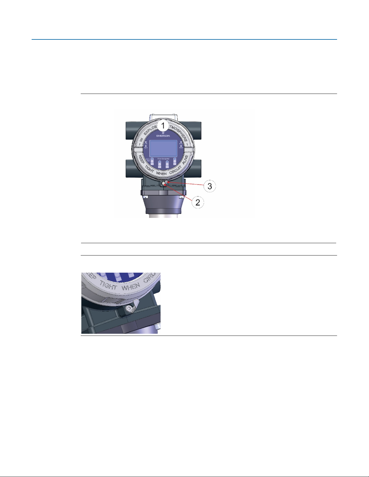
Front End Cap with Retaining Clamp Fitted
D301785X012
August 2020
1 End Cap
2 Screw
3 Retaining Clamp
Retaining Clamp in Place
To loosen or tighten the screw, use a 3mm hexagonal wrench. When tightening, torque to 12 in-lbs
(1.4 N m).
3
Emerson FB1100 Flow Computer Quick Start Guide
D301785X012
August 2020
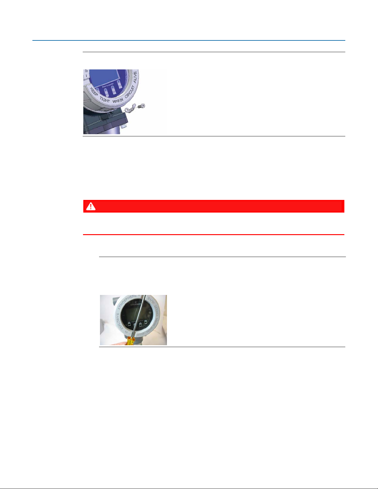
Retaining Clamp and Screw
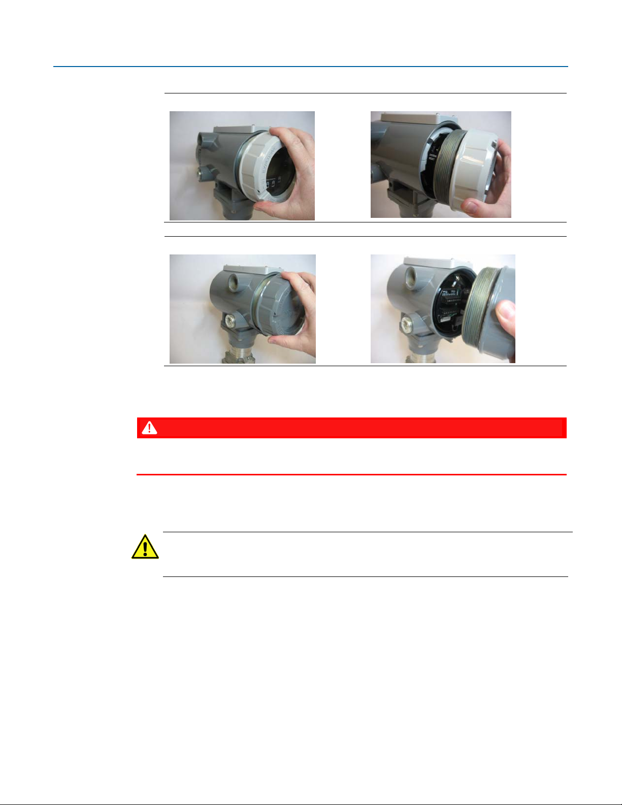
Removing the Front or Rear End Cap
The flow computer includes two threaded end caps (covers). The front end cap includes a window
for viewing the HMI module, while the rear end cap provides access to the terminal plate for power
and I/O wiring.
DANGER
EXPLOSION HAZARD: Never remove end cap(s) in a hazardous location. Removing end cap(s) in
a hazardous location could result in an explosion.
1. Remove the retaining clamp (if present). Grasp the end cap (front or rear).
Note
If you need more leverage to open or close an end cap than you can get with your hand,
you can place a long screwdriver or other appropriate tool across the two notches in the
end cap to act as a pry bar:
2. Unscrew the end cap turning it counter-clockwise until the end cap comes off. Set it aside in
a safe location.
4
Emerson FB1100 Flow Computer Quick Start Guide
D301785X012
August 2020
Front End Cap
Removing Front End Cap
Rear End Cap
Removing Rear End Cap
Replacing the Front or Rear End Cap
DANGER
EXPLOSION HAZARD: Never remove end cap(s) in a hazardous location. Removing end cap(s) in
a hazardous location could result in an explosion.
1. Grasp the end cap (front or rear).
2. Carefully align the end cap threads with the threads of the enclosure.
Important
When replacing the rear end cap, ensure wires connecting to the terminal plate do not get
crimped or caught between the end cap threads and the enclosure.
3. Screw the end cap clockwise (eight full turns) until it is tightly sealed to the enclosure.
4. Replace the retaining clamp (if applicable).
5

Emerson FB1100 Flow Computer Quick Start Guide
D301785X012
August 2020
Bolting Considerations
DANGER
EXPLOSION HAZARD: Ensure the area in which you perform this operation is non-hazardous.
Performing this operation in a hazardous area could result in an explosion.
If the flow computer installation requires assembly of a process flange, manifold, or flange
adapters, follow these assembly guidelines to ensure a tight seal for optimal performance
characteristics of the flow computer.
Only use bolts supplied with the flow computer or sold by Emerson as spare parts. Refer to figures
below for common flow computer assemblies with the bolt length required for proper flow
computer installation.
Note
For all other manifolds, contact your local Emerson Sales office or Emerson Impact Partner.
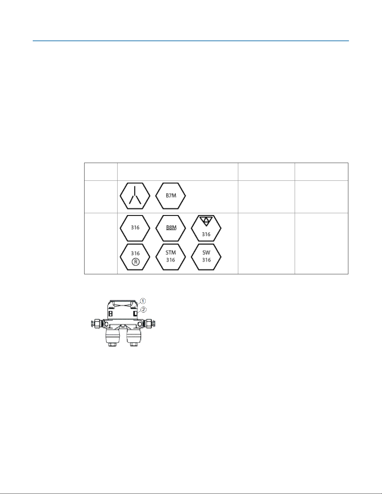
Bolts are typically carbon steel or stainless steel. Confirm the material by viewing the markings on
the head of the bolt and referencing Table 2. If bolt material is not shown in the table, contact your
local Emerson representative for more information.
Transmitter with coplanar flange
Transmitter with coplanar flange and optional flange adapters
Transmitter with coplanar flange and optional flange adapters
6
Emerson FB1100 Flow Computer Quick Start Guide
D301785X012
August 2020
Use the following bolt installation procedure:
1. Carbon steel bolts do not require lubrication. Stainless steel bolts are factory-coated with a
lubricant to ease installation. Do not apply any additional lubricant when installing either
type of bolt.
2. Finger-tighten the bolts.
3. Torque the bolts to the initial torque value using a crossing pattern. See Table 2 for
initial torque value.
4. Torque the bolts to the final torque value using the same crossing pattern. See Table 2 for
final torque value.
5. Verify that the flange bolts protrude through the sensor module before applying
pressure.
Table 2: Torque Values for the Flange and Flange Adapter Bolts
Bolt
material
Carbon
Steel (CS)
Stainless
Steel (SST)
Proper Bolt Installation
1 Bolt
2 Sensor module
Head markings
Initial torque
300 in. -lbs.
(33.9 N m)
150 in. -lbs.
(16.9 N m)
Final torque
650 in. -lbs.
(73.4 N m)
300 in. -lbs.
(33.9 N m)
7
Emerson FB1100 Flow Computer Quick Start Guide
D301785X012
August 2020
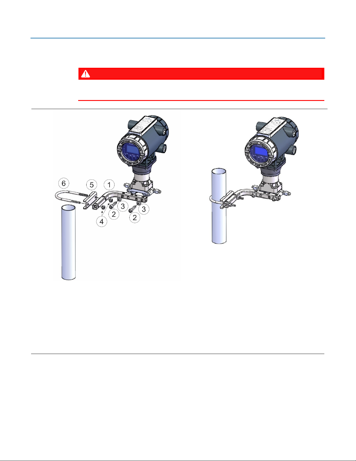
Coplanar Mounting Kit
DANGER
EXPLOSION HAZARD: Ensure the area in which you perform this operation is non-hazardous.
Performing this operation in a hazardous area could result in an explosion.
1 Tubular L-shaped bracket
2 3/8-16 x 1 ½ in socket head wire lockable screw (2) — Apply Killark® LUBG-6 anti-seize lubricant to threads.
Torque screws to 30 in-lbs (3.4 N m)
3 Split 3/8 lock washer (2)
4 5/16-18 keps nut (2). Apply Loctite® 222TM Low Strength Purple Threadlocker to nuts. Torque nuts to 30 in-
lbs (3.4 N m)
5 U-bolt bracket
6 2-inch diameter pipe U-bolt
8
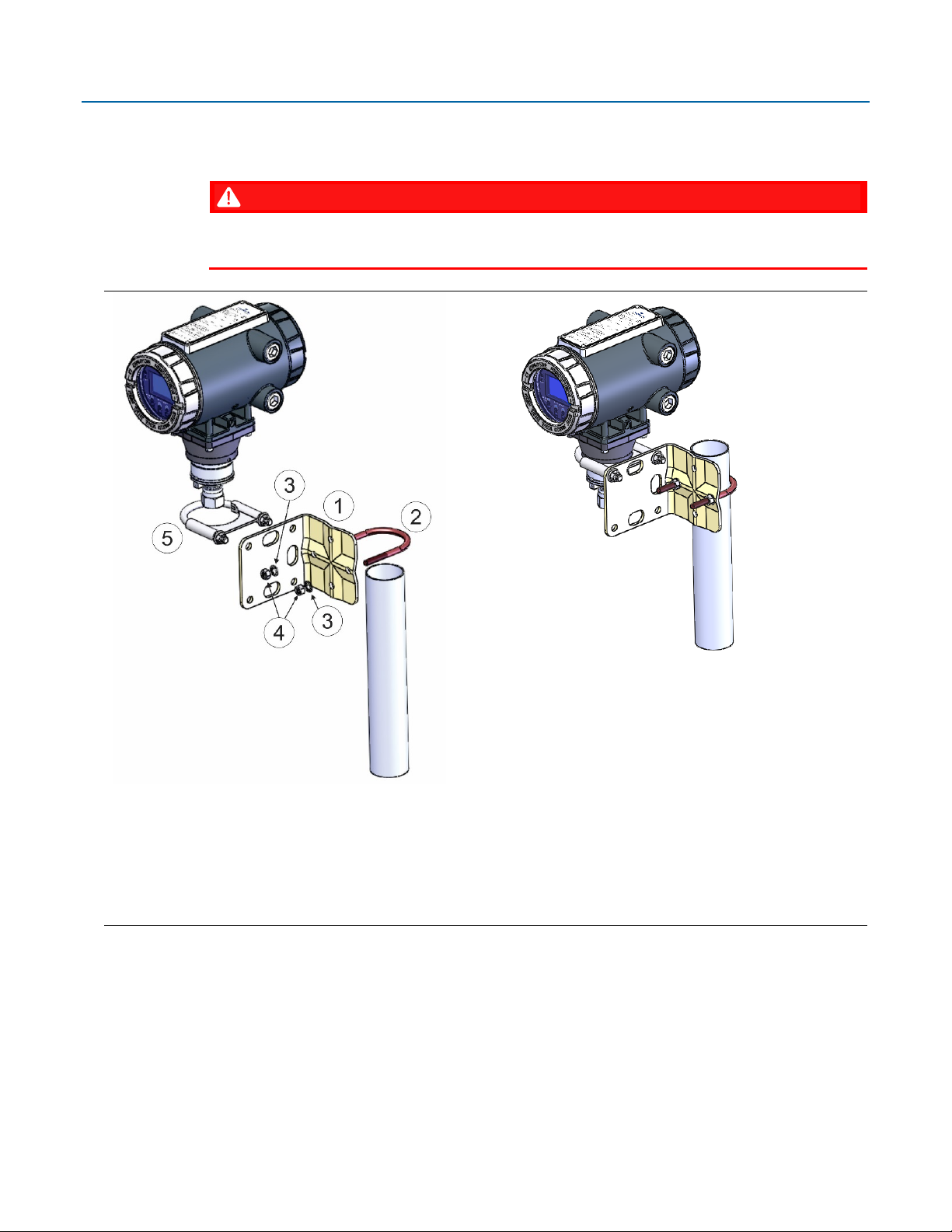
Inline Mounting Kit
Emerson FB1100 Flow Computer Quick Start Guide
D301785X012
August 2020
DANGER
EXPLOSION HAZARD: Ensure the area in which you perform this operation is non-hazardous.
Performing this operation in a hazardous area could result in an explosion.
1 Pipe mounting bracket
2 U-bolt 2 ½ inch diam. pipe (5/16-18 x 3.75 long)
3 5/16 flat lock washer (2)
4 5/16-18 300 series hex nut (2) - Apply Loctite 222 Low Strength Purple Threadlocker to threads. Torque
nuts to 30 in-lbs (3.4 N m)
5 U-bolt clamp assembly - Apply Loctite 222 threadlocker to threads. Torque nuts to 30 in-lbs (3.4 N m)
9
 Loading...