

Page 1

Form A6126
Part Number D301174X012
March 2009
DS800 Development Suite
Software
User Manual
Page 2

Revision Tracking Sheet
March 2009
This manual is periodically altered to incorporate new or updated information. The date revision level of each page is
indicated at the bottom of the page opposite the page number. A major change in the content of the manual also
changes the date of the manual, which appears on the front cover. Listed below is the date revision level of each page.
Page Revision
All Pages 05/02
55, 112-117, 119-120,242, 419-425, 431-454, 538-540,
542, 546-549, 552-553, 556, 559-563, 566-570, 588,
594-5950 08/02
All Pages 07/06
All Pages 03/09
© 2002 - 2009 Remote Automation Solutions, division of Emerson Process Management. All rights reserved.
NOTICE
Remote Automation Solutions (“RAS”), division of Emerson Process Management shall not be liable for technical or
editorial errors in this manual or omissions from this manual. RAS MAKES NO WARRANTIES, EXPRESSED OR
IMPLIED, INCLUDING THE IMPLIED WARRANTIES OF MERCHANTABILITY AND FITNESS FOR A PARTICULAR
PURPOSE WITH RESPECT TO THIS MANUAL AND, IN NO EVENT SHALL RAS BE LIABLE FOR ANY
INCIDENTAL, PUNITIVE, SPECIAL OR CONSEQUENTIAL DAMAGES INCLUDING, BUT NOT LIMITED TO, LOSS
OF PRODUCTION, LOSS OF PROFITS, LOSS OF REVENUE OR USE AND COSTS INCURRED INCLUDING
WITHOUT LIMITATION FOR CAPITAL, FUEL AND POWER, AND CLAIMS OF THIRD PARTIES.
Bristol, Inc., Bristol Canada, BBI SA de CV and Emerson Process Management Ltd., Remote Automation Solutions
division (UK) are wholly owned subsidiaries of Emerson Electric Co. doing business as Remote Automation Solutions
(“RAS”), a division of Emerson Process Management. ROC, FloBoss, ROCLINK, Bristol, Bristol Babcock,
ControlWave, TeleFlow and Helicoid are trademarks of RAS. AMS, PlantWeb and the PlantWeb logo are marks of
Emerson Electric Co. The Emerson logo is a trademark and service mark of the Emerson Electric Co. All other
trademarks are property of their respective owners.
The contents of this publication are presented for informational purposes only. While every effort has been made to
ensure informational accuracy, they are not to be construed as warranties or guarantees, express or implied, regarding
the products or services described herein or their use or applicability. RAS reserves the right to modify or improve the
designs or specifications of such products at any time without notice. All sales are governed by RAS’ terms and
conditions which are available upon request.
RAS does not assume responsibility for the selection, use or maintenance of any product. Responsibility for proper
selection, use and maintenance of any RAS product remains solely with the purchaser and end-user.
DS800 Development Suite 2.10 - User Manual
Page 3

Table of Contents
Workbench _______________________________________ 1
Appearance ............................................................................................................ 3
Title Bar.......................................................................................................... 4
Menu Bar ........................................................................................................ 5
Toolbars ........................................................................................................ 14
Standard Toolbar......................................................................................15
Debug Toolbar .........................................................................................17
Window Buttons Toolbar.........................................................................19
Layers Toolbar.........................................................................................19
Version Source Control Toolbar..............................................................20
Options Toolbar .......................................................................................20
I/O Wiring Toolbar ..................................................................................20
Workspace .................................................................................................... 22
Zoom ........................................................................................................23
Output Window ............................................................................................ 24
Contextual Menus......................................................................................... 25
Status Bar...................................................................................................... 25
Customization ...................................................................................................... 26
Directory Structure .............................................................................................. 29
Working with Projects ......................................................................................... 32
Creating Projects........................................................................................... 34
Opening and Closing Projects ...................................................................... 36
Saving Projects ............................................................................................. 39
Renaming Projects........................................................................................ 39
Adding a Project Description........................................................................ 40
Printing Projects ........................................................................................... 40
Project Access Control......................................................................................... 41
Importing and Exporting Workbench Elements .................................................. 43
Uploading Workbench Elements from Targets ................................................... 46
Link Architecture View ....................................................................................... 48
Resources...................................................................................................... 48
Resource Window Workspace.................................................................49
Creating Resources ..................................................................................50
DS800 Development Suite 2.1 - Table of Contents i
Page 4

Renaming Resources ...............................................................................51
Copying Resources ..................................................................................51
Pasting Resources ....................................................................................52
Deleting Resources ..................................................................................53
Editing Resource Properties ......................................................................... 54
Resource Identification............................................................................55
Compilation Options................................................................................55
Run-time Settings ...................................................................................59
Resource Network Parameters.................................................................62
Custom Resource Parameters ..................................................................63
Resource Access Control.........................................................................64
Resource Description...............................................................................66
Variable Bindings ........................................................................................ 67
Internal Bindings .....................................................................................71
Linking Resources .............................................................................74
Deleting Resource Links....................................................................76
Viewing the Internal Bindings Defined for Resources ......................77
Hiding and Showing Resource Links ................................................77
Defining Internal Variable Bindings..................................................78
Editing Internal Variable Bindings ....................................................80
Deleting Internal Variable Bindings ..................................................80
External Bindings ...................................................................................81
Defining Producer Variable Groups ................................................. 83
Editing Producer Variable Groups.....................................................85
Deleting Producer Variable Groups...................................................85
Linking Resources for External Bindings .........................................86
Editing External Resource Links .......................................................87
Defining External Variable Bindings.................................................88
Editing External Variable Bindings ...................................................89
Deleting External Variable Bindings .................................................89
Parameters .................................................................................................... 90
Variable Groups ........................................................................................... 91
Creating Variable Groups........................................................................91
Opening Variable Groups........................................................................91
Importing or Exporting Variables ................................................................ 93
POUs (Program Organization Units) ........................................................... 96
Programs..................................................................................................96
Functions .................................................................................................98
Function Blocks.......................................................................................99
ii DS800 Development Suite 2.1 - User Manual
Page 5

Creating POUs .........................................................................................99
Manipulating POUs ...............................................................................100
Creating FC Sub-programs ....................................................................102
Creating SFC Child POUs .....................................................................102
Changing Hierarchy Level.....................................................................103
Controlling Access to POUs ..................................................................104
Generating Debug and Monitoring Information ....................................107
Editing a POU Description ....................................................................108
Hardware Architecture View ............................................................................. 109
Configurations ............................................................................................ 110
Creating Configurations.........................................................................110
Deleting Configurations.........................................................................111
Moving Configurations..........................................................................112
Inserting Resources................................................................................112
Moving Resources Between Configurations .........................................113
Configuration Properties............................................................................. 114
Configuration Link to ROCLINK Configuration File ...........................115
Configuration Target Definitions...........................................................117
Target Access Control............................................................................118
Configuration Description .....................................................................119
Networks..................................................................................................... 120
Creating Networks .................................................................................120
Moving Networks ..................................................................................121
Connections ................................................................................................ 123
Creating Connections.............................................................................123
Deleting Connections.............................................................................124
Dictionary View................................................................................................. 125
Appearance ................................................................................................. 126
Variables Tree............................................................................................. 127
Parameters Tree .......................................................................................... 128
Types Tree .................................................................................................. 129
Creating Structures.................................................................................129
Renaming Structures..............................................................................130
Deleting Structures.................................................................................130
Defined Words Tree ................................................................................... 130
Working with the Grids .............................................................................. 131
Resizing Columns ..................................................................................132
Selecting Rows and Elements................................................................132
DS800 Development Suite 2.1 - Table of Contents iii
Page 6

Editing the Contents of the Grid............................................................133
Adding or Inserting Rows......................................................................134
Moving Rows ........................................................................................135
Expanding or Collapsing Grid Components..........................................135
Cutting, Copying, and Deleting Elements .............................................136
Finding and Replacing Elements...........................................................137
Pasting Elements....................................................................................138
Sorting the Grid .....................................................................................138
Duplicating Rows ..................................................................................139
Renumbering Addresses ........................................................................140
Printing a Grid .......................................................................................141
Variables Grid ............................................................................................ 142
Parameters Grid.......................................................................................... 143
Types Grid.................................................................................................. 144
Defined Words Grid ................................................................................... 145
Defining TLP Variables ............................................................................. 146
Initial Values .............................................................................................. 150
Validation ................................................................................................... 153
Cell-level Validation..............................................................................153
Row-level Validation.............................................................................153
Database-level Validation......................................................................154
I/O Wiring View................................................................................................ 155
Appearance................................................................................................. 156
I/O Wiring Tree View ................................................................................ 157
I/O Wiring Grid View ................................................................................ 159
Working with the I/O Wiring Tool............................................................. 160
TLP Devices (Automatic Wiring) .........................................................162
Analog Input - 4 Point ...........................................................................163
Analog Output - 4 Point.........................................................................163
Discrete Input - 8 Point..........................................................................164
Discrete Output - 5 Point .......................................................................164
Multi-Variable Sensor Input - 6 Point ...................................................165
Pulse Input - 2 Point ..............................................................................166
RTD Input - 2 Point ...............................................................................167
System Analog Input - 5 Point ..............................................................167
Thermocouple Input - 5 Point................................................................168
Adding I/O Devices ...............................................................................169
Opening Devices....................................................................................170
Deleting Devices and Conversions........................................................171
iv DS800 Development Suite 2.1 - User Manual
Page 7

Setting the Real or Virtual Attribute......................................................171
Wiring Channels ....................................................................................172
Mapping Channels .................................................................................172
Freeing Channels ...................................................................................174
Run-time System Events.................................................................................... 175
Logging Events........................................................................................... 175
Viewing Events........................................................................................... 176
Language Editors ............................................................................................... 181
Common Editor Features............................................................................ 181
Appearance ............................................................................................182
Menu Bar..........................................................................................183
Toolbars............................................................................................184
Standard Toolbar ........................................................................185
Options Toolbar..........................................................................186
Debug Toolbar............................................................................187
SFC Breakpoints Toolbar...........................................................189
SFC Tools...................................................................................189
Flow Chart Tools........................................................................191
ST Tools .....................................................................................192
IL Tools ......................................................................................193
LD Tools.....................................................................................194
FBD Tools ..................................................................................195
Workspace........................................................................................197
Contextual Menus ............................................................................199
Output Window................................................................................199
Status Bar .........................................................................................200
Inserting Identifiers................................................................................201
Inserting Blocks .....................................................................................203
Printing POUs ........................................................................................205
Opening the Dictionary..........................................................................205
Opening Another POU...........................................................................206
Finding and Replacing in POUs ............................................................207
SFC Editor .................................................................................................. 209
Appearance ............................................................................................210
Menu Bar ...............................................................................................211
DS800 Development Suite 2.1 - Table of Contents v
Page 8

Working with the Editor ........................................................................214
SFC Elements...................................................................................215
Initial Step ..................................................................................215
Step.............................................................................................216
Transition ...................................................................................216
Divergence/Convergence ...........................................................217
Creating New Branches........................................................219
Deleting Branches ................................................................220
Link ............................................................................................221
Jump ...........................................................................................222
Managing Elements .........................................................................223
Select ..........................................................................................223
Rename.......................................................................................224
Move ..........................................................................................225
Cut ..............................................................................................225
Copy ...........................................................................................225
Paste ...........................................................................................226
Delete .........................................................................................227
Goto............................................................................................227
Level 2 .............................................................................................228
Coding Action Blocks for Steps.................................................229
Coding Conditions for Transitions.............................................231
Moving Action Blocks Up or Down ..........................................232
Deleting an Action Block...........................................................233
Renumbering Charts ........................................................................233
FC Editor .................................................................................................... 235
Appearance ............................................................................................235
Menu Bar ...............................................................................................236
Working with Flow Charts ....................................................................239
Flow Chart Elements........................................................................240
Action.........................................................................................240
Test.............................................................................................240
IF-THEN-ELSE .........................................................................241
DO-WHILE................................................................................242
WHILE-DO................................................................................242
Flow............................................................................................243
Connector ...................................................................................244
I/O Specific ................................................................................244
vi DS800 Development Suite 2.1 - User Manual
Page 9

Comment ....................................................................................245
Sub-Program...............................................................................245
Managing Elements..........................................................................246
Select ..........................................................................................246
Cut ..............................................................................................247
Copy ...........................................................................................247
Paste............................................................................................248
Delete..........................................................................................248
Move...........................................................................................248
GoTo...........................................................................................249
Renumber ...................................................................................249
Level 2..............................................................................................250
Level 2 Window .........................................................................251
Edit the Level 2 ..........................................................................252
Multi-language Editor................................................................................. 253
Appearance ............................................................................................254
Menu Bar ...............................................................................................256
Multi-Language Elements......................................................................260
ST/IL Elements ................................................................................260
LD Elements.....................................................................................261
Contact on the Left ....................................................................261
Contact on the Right ..................................................................261
Parallel Contact .........................................................................262
Coil ............................................................................................262
Block on the Left .......................................................................262
Block on the Right .....................................................................262
Parallel Block ............................................................................262
Jump ..........................................................................................262
Label...........................................................................................263
Return ........................................................................................263
Change Coil/Contact Type ........................................................263
Insert New Rung ........................................................................264
Other Operations .......................................................................264
FBD Elements ..................................................................................265
Variable ......................................................................................266
Function Block ...........................................................................267
Link ...........................................................................................267
Corner ........................................................................................267
Jump ..........................................................................................268
DS800 Development Suite 2.1 - Table of Contents vii
Page 10

Label ..........................................................................................268
Return.........................................................................................269
LD Elements...............................................................................270
Left Power Bar ...................................................................270
Contacts ..............................................................................270
LD Vertical "OR" Connection ............................................270
Coils.....................................................................................271
Right Power Bar .................................................................271
Comment ....................................................................................272
Managing Elements ...............................................................................273
Select................................................................................................273
Resize...............................................................................................274
Undo/Redo .......................................................................................274
Move ................................................................................................275
Cut....................................................................................................275
Copy.................................................................................................276
Paste .................................................................................................276
Paste Special ....................................................................................277
Delete ...............................................................................................277
Select All..........................................................................................278
Find Matching Name .......................................................................278
Find Matching Coil..........................................................................278
Go to Line ........................................................................................279
Display/Hide Comments..................................................................279
Libraries............................................................................................................. 281
Creating Libraries....................................................................................... 281
Using Libraries in a Project........................................................................ 282
Debug................................................................................................................. 289
Status Information ...................................................................................... 290
Download ................................................................................................... 293
Debug/Simulate .......................................................................................... 295
Start / Stop a Resource...........................................................................297
Resource Execution Mode.....................................................................298
Real-time Mode ...............................................................................298
Cycle-to-cycle Mode........................................................................299
viii DS800 Development Suite 2.1 - User Manual
Page 11

Step-by-step Mode ...........................................................................299
Setting Breakpoints ....................................................................301
Removing Breakpoints ...............................................................301
Stepping in POUs .......................................................................302
Set Cycle Time.......................................................................................303
Write / Lock / Unlock ............................................................................304
Diagnosis................................................................................................307
SFC Breakpoints ....................................................................................311
Breakpoint on Step Activation .........................................................312
Breakpoint on Step Deactivation .....................................................313
Breakpoint on Transition..................................................................314
Transition Clearing Forcing .............................................................315
Spying Variables....................................................................................316
Adding Variables to the Spy List .....................................................316
Selecting Variables in the Spy List ..................................................317
Removing Variables from the Spy List............................................318
Rearranging the Spy List..................................................................318
Saving a Spy List .............................................................................318
Opening an Existing Spy List ..........................................................319
Forcing the Value of a Spy List Variable.........................................319
Simulate a Panel of I/Os ............................................................................. 320
Appearance ............................................................................................322
Menu Bar..........................................................................................323
Toolbar .............................................................................................324
Contextual Menu..............................................................................325
Displaying I/O Device Window Headers.........................................325
Moving or Hiding the Browser ........................................................326
Online Changes........................................................................................... 327
Code Sequences .....................................................................................327
Variables ................................................................................................329
Declared Variables ...........................................................................329
Function Block Instances .................................................................330
Compiler Allocated Hidden Variables .............................................330
I/O Devices ............................................................................................331
Memory Requirements...........................................................................331
Miscellaneous Limitations.....................................................................331
Operations..............................................................................................332
Debug Function Block Instances................................................................ 334
Clean Stored Code ...................................................................................... 336
DS800 Development Suite 2.1 - Table of Contents ix
Page 12

Document Generator.......................................................................................... 337
Table of Items............................................................................................. 338
Printing Options ......................................................................................... 340
Preview....................................................................................................... 342
Code Generator.................................................................................................. 345
Build ........................................................................................................... 345
Build a POU...........................................................................................346
Building Resources / Projects................................................................347
Stopping Builds .....................................................................................348
Cleaning Projects...................................................................................348
Compiler Options ....................................................................................... 349
C Source Code............................................................................................ 351
Project Tree View.............................................................................................. 353
Cross References Browser................................................................................. 355
Calculating Cross References..................................................................... 357
Browsing the POUs of a Project................................................................. 357
Defining Search Options ............................................................................ 358
Version Source Control ..................................................................................... 359
Performing a Check in of a Workbench Element....................................... 363
Viewing the History of Workbench Elements ........................................... 364
Getting a Previous Version....................................................................365
Comparing Current and Previous Versions ...........................................365
Ac cessing Details for a Previous Version ............................................366
Creating a History Report......................................................................366
Language Reference ______________________________ 367
Project Architecture........................................................................................... 368
Programs..................................................................................................... 368
Cyclic and Sequential Operations .............................................................. 369
Child SFC POUs ........................................................................................ 370
FC Sub-Programs ....................................................................................... 371
Functions .................................................................................................... 371
Function Blocks.......................................................................................... 373
Description Language................................................................................. 375
Execution Rules.......................................................................................... 376
x DS800 Development Suite 2.1 - User Manual
Page 13

Common Objects ............................................................................................... 377
Data Types.................................................................................................. 377
Standard IEC 61131 Types ....................................................................377
User Types: Arrays ................................................................................379
User Types: Structures...........................................................................380
Constant Expressions.................................................................................. 381
Boolean Constant Expressions...............................................................381
Short Integer Constant Expressions.......................................................381
Double Integer Constant Expressions....................................................382
Real Constant Expressions.....................................................................382
Timer Constant Expressions ..................................................................383
String Constant Expressions ..................................................................383
Variables..................................................................................................... 385
Reserved Keywords ...............................................................................385
Directly Represented Variables .............................................................387
Information on Variables .......................................................................389
Boolean Variables (BOOL) ...................................................................390
Short Integer Variables (SINT)..............................................................390
Double Integer Variables (DINT)..........................................................390
Real Variables (REAL)..........................................................................390
Timer Variables (TIME)........................................................................391
String Variables (STRING) ...................................................................391
Comments................................................................................................... 392
Defined Words............................................................................................ 392
SFC Language.................................................................................................... 395
SFC Main Format ....................................................................................... 395
SFC Basic Components .............................................................................. 396
Steps and Initial Steps............................................................................396
Transitions..............................................................................................397
Oriented Links .......................................................................................398
Jump to a Step........................................................................................398
Divergences and Convergences.................................................................. 400
Single Divergences (OR) .......................................................................400
Double Divergences (AND) ..................................................................402
Actions Within Steps .................................................................................. 404
Boolean Actions.....................................................................................404
Pulse Actions .........................................................................................405
Non-stored Actions ................................................................................406
SFC Actions...........................................................................................407
DS800 Development Suite 2.1 - Table of Contents xi
Page 14

List of Instructions.................................................................................408
Calling Functions and Function Blocks.................................................409
Conditions Attached to Transitions............................................................ 410
Condition Programmed in ST................................................................410
Condition Programmed in LD ...............................................................411
Condition Programmed in IL.................................................................411
Calling Functions from a Transition......................................................412
Calling Function Blocks from a Transition ...........................................413
SFC Dynamic Behavior.............................................................................. 414
SFC Program Hierarchy ............................................................................. 415
FC Language...................................................................................................... 417
FC Basic Components ................................................................................ 417
FC BEGIN .............................................................................................418
FC END .................................................................................................418
FC Flow Links .......................................................................................419
FC Actions.............................................................................................420
FC Conditions........................................................................................420
Other FC Components................................................................................ 422
FC Sub-Program ....................................................................................422
FC I/O Specific Actions.........................................................................423
FC Connectors .......................................................................................424
FC Comments ........................................................................................424
FC Complex Structure Examples ..........................................................425
FC Dynamic Behavior................................................................................ 426
FC Checking............................................................................................... 426
FC Examples .............................................................................................. 427
FBD Language................................................................................................... 429
FBD Diagram Main Format ....................................................................... 429
RETURN Statement ................................................................................... 431
Jumps and Labels ....................................................................................... 431
Boolean Negation ....................................................................................... 433
Calling Functions and Function Blocks ..................................................... 433
LD Language ..................................................................................................... 435
Power Rails and Connection Lines ............................................................ 436
Multiple Connections ................................................................................. 437
Basic LD Contacts and Coils...................................................................... 439
Direct Contact........................................................................................440
Inverted Contact.....................................................................................440
xii DS800 Development Suite 2.1 - User Manual
Page 15

Contact with Rising Edge Detection......................................................441
Contact with Falling Edge Detection.....................................................442
Direct Coil..............................................................................................443
Inverted Coil ..........................................................................................444
SET Coil.................................................................................................445
RESET Coil ...........................................................................................446
Coil with Rising Edge Detection ...........................................................447
Coil with Falling Edge Detection ..........................................................448
RETURN Statement ................................................................................... 449
Jumps and Labels........................................................................................ 450
BLOCKS in LD .......................................................................................... 451
ST Language ...................................................................................................... 453
ST Main Syntax .......................................................................................... 453
Expressions and Parentheses ...................................................................... 455
Functions or Function Block Calls ............................................................. 456
Calling Functions...................................................................................456
Calling Function Blocks ........................................................................457
ST Operators............................................................................................... 459
ST Basic Statements ................................................................................... 459
Assignment.......................................................................................459
RETURN Statement...............................................................................460
IF-THEN-ELSIF-ELSE Statement ........................................................461
CASE Statement ....................................................................................462
WHILE Statement..................................................................................463
REPEAT Statement ...............................................................................464
FOR Statement.......................................................................................465
EXIT Statement .....................................................................................466
ST Extensions ............................................................................................. 467
GSTART Statement in SFC Action.......................................................468
GKILL Statement in SFC Action ..........................................................469
GFREEZE Statement in SFC Action.....................................................470
GRST Statement in SFC Action ............................................................471
GSTATUS Statement in SFC Action ....................................................472
IL Language....................................................................................................... 473
IL Main Syntax........................................................................................... 473
Labels.....................................................................................................474
Operator Modifiers.................................................................................474
Delayed Operations................................................................................475
DS800 Development Suite 2.1 - Table of Contents xiii
Page 16

IL Operators ............................................................................................... 476
LD Operator...........................................................................................477
ST Operator ...........................................................................................478
S Operator..............................................................................................478
R Operator .............................................................................................479
JMP Operator.........................................................................................480
RET Operator.........................................................................................481
) Operator...............................................................................................482
Calling Functions...................................................................................483
Calling Function Blocks: CAL Operator...............................................485
Standard Operators ............................................................................................ 487
* ................................................................................................................. 488
+ ................................................................................................................. 489
- .................................................................................................................. 491
/ .................................................................................................................. 492
1 GAIN ....................................................................................................... 494
AND ........................................................................................................... 495
ANY_TO_BOOL ....................................................................................... 496
ANY_TO_SINT ......................................................................................... 498
ANY_TO_DINT ........................................................................................ 499
ANY_TO_REAL........................................................................................ 501
ANY_TO_TIME ........................................................................................ 502
ANY_TO_STRING.................................................................................... 504
Equal........................................................................................................... 505
Greater Than or Equal ................................................................................ 507
Greater Than............................................................................................... 508
Less Than or Equal..................................................................................... 510
Less Than ................................................................................................... 511
NEG............................................................................................................ 512
NOT............................................................................................................ 514
Not Equal.................................................................................................... 515
OR .............................................................................................................. 516
TMR ........................................................................................................... 517
XOR............................................................................................................ 518
Standard Functions ............................................................................................ 521
ABS ............................................................................................................ 522
ACOS ......................................................................................................... 523
AND_MASK.............................................................................................. 524
xiv DS800 Development Suite 2.1 - User Manual
Page 17

ASCII.......................................................................................................... 525
ASIN........................................................................................................... 526
ATAN ......................................................................................................... 527
CHAR ......................................................................................................... 528
COS ............................................................................................................ 530
CURRENT_ISA_DATE............................................................................. 531
DELETE ..................................................................................................... 532
EXPT .......................................................................................................... 533
FIND........................................................................................................... 534
INSERT ...................................................................................................... 536
LEFT........................................................................................................... 537
LIMIT ......................................................................................................... 539
LOG ............................................................................................................ 540
MAX........................................................................................................... 541
MID............................................................................................................. 542
MIN............................................................................................................. 543
MLEN......................................................................................................... 544
MOD........................................................................................................... 546
MUX4......................................................................................................... 547
MUX8......................................................................................................... 549
NOT_MASK............................................................................................... 550
ODD............................................................................................................ 551
OR_MASK ................................................................................................. 553
POW ........................................................................................................... 554
RAND......................................................................................................... 555
REPLACE .................................................................................................. 556
RIGHT ........................................................................................................ 558
ROL ............................................................................................................ 559
ROR ............................................................................................................ 560
SEL ............................................................................................................. 562
SHL............................................................................................................. 563
SHR ............................................................................................................ 564
SIN.............................................................................................................. 565
SQRT .......................................................................................................... 566
SUB_DATE_DATE ................................................................................... 567
TAN ............................................................................................................ 569
TRUNC....................................................................................................... 570
XOR_MASK .............................................................................................. 571
DS800 Development Suite 2.1 - Table of Contents xv
Page 18

Standard Function Blocks.................................................................................. 573
ALARM...................................................................................................... 575
AVERAGE................................................................................................. 575
BLINK........................................................................................................ 577
CMP............................................................................................................ 578
CONNECT ................................................................................................. 579
CTD ............................................................................................................ 581
CTU ............................................................................................................ 582
CTUD ......................................................................................................... 583
DBG_CLR_GET_ERR .............................................................................. 585
DBG_CLR_SET_ERR............................................................................... 585
DBG_GET_ERR ........................................................................................ 586
DBG_SET_ERR......................................................................................... 586
DERIVATE ................................................................................................ 587
EVENT....................................................................................................... 588
F_TRIG ...................................................................................................... 588
HYSTER .................................................................................................... 589
INTEGRAL ................................................................................................ 590
R_TRIG ...................................................................................................... 591
REQUEST_LICENSE................................................................................ 592
RS ............................................................................................................... 593
SET_PRIORITY ........................................................................................ 594
SIG_GEN ................................................................................................... 595
SOFT_POINT_READ................................................................................ 596
SOFT_POINT_WRITE.............................................................................. 597
SR ............................................................................................................... 598
STACKINT ................................................................................................ 600
TLP_GET_DINT........................................................................................ 601
TLP_GET_REAL....................................................................................... 602
TLP_GET_SINT ........................................................................................ 603
TLP_GET_STRING................................................................................... 604
TLP_GET_TLP .......................................................................................... 605
TLP_SET_DINT ........................................................................................ 606
TLP_SET_REAL ....................................................................................... 607
TLP_SET_SINT......................................................................................... 608
TLP_SET_STRING ................................................................................... 609
TOF ............................................................................................................ 609
TON............................................................................................................ 610
TP ............................................................................................................... 611
xvi DS800 Development Suite 2.1 - User Manual
Page 19

URCV_S..................................................................................................... 612
USEND_S................................................................................................... 613
Glossary ............................................................................................................. 615
Copyright ........................................................................................................... 661
DS800 Development Suite 2.1 - Table of Contents xvii
Page 20

Page 21

Workbench
The DS800 software suite supports both the ROC800-Series and the FloBoss 107 flow
computers from Remote Automation Solutions (RAS). To simplify usage, this
documentation refers to both devices as the “RAS device.” If there is a situation where we
restrict functionality to either the ROC800-Series or the FB107, we note it.
The Workbench is the environment in which you develop multi-process control projects made
up of virtual machines running on hardware components, called target nodes. The development
process consists of creating projects made up of configurations, representing, individual target
nodes, on which one or more instances of resources, i.e., virtual machines, are downloaded. At
runtime, the virtual machines run on these target nodes.
Projects can be developed using any of the five languages of the IEC 61131 standard: SFC:
Sequential Function Chart (or Grafcet), FBD: Function Block Diagram, LD: Ladder Diagram,
ST: Structured Text, and IL: Instruction List. You can also use the Flow Chart language. When
building, resources are compiled to produce very fast "target independent code" (TIC) or
"C" code.
Within resources, you can declare variables using standard IEC 61131 data types (i.e., Boolean,
integer, real, etc.) or user-defined types such as arrays or structures. For defined variables, you
can set up alarms, events, and trending. Furthermore, field communications allow you to
connect variables to field equipment. Resources can share variables using internal bindings or
external bindings. Internal bindings are between resources within the same project. External
bindings are between resources belonging to different projects.
DS800 Development Suite 2.1 - Workbench 1
Page 22

You develop projects on a Windows development platform, in the Workbench and language
editors. The Workbench graphically represents and organizes configurations, resources, POUs,
and networks within a project from multiple views:
link architecture
hardware architecture
dictionary
I/O wiring
bindings
Libraries made up of configurations and resources enable you to define functions and function
blocks for reuse throughout projects.
Individual resources, from the configurations making up a project, are downloaded, using the
ETCP or ISARSI (serial link) network, onto target RAS device nodes running real-time
operating systems. Communication between configurations can be implemented using the
TCP\IP network. You can choose to implement any other network.
You can choose to simulate the running of a project, after building a project, using high-level
debugging tools, before actually downloading the resources making up configurations to the
target nodes.
You can set four levels of access control in a Workbench application:
password protection and read-only mode for a complete project
password protection and read-only mode for individual resources
password protection for individual POUs
password protection for a target
2 DS800 Development Suite 2.1 - User Manual
Page 23

Appearance
Title bar
Menu bar
Tool bars
Workspace
Output window
Status bar
DS800 Development Suite 2.1 - Workbench 3
Page 24

Title Bar
For help locating the Title Bar, see the Appearance diagram. The Title Bar displays the
application name and the filename of the active project, if any are open, along with the current
view (Hardware Architecture, Link Architecture, Dictionary or I/O Wiring).
Control Icon
At the left end of the Title Bar is the Control Icon, which is used to access the Control Menu
(see following section). Double-clicking on the Control Icon closes the Workbench.
Control Menu
Clicking on the Control icon opens the Control Menu. The Control Menu is used to position
the Main Window or to exit.
Window Buttons
The standard window buttons appear at the right end of the Title Bar. Use these to resize or
close the Window.
4 DS800 Development Suite 2.1 - User Manual
Page 25

Menu Bar
The options available from the menu bar differ slightly for the hardware architecture and link
architecture views of a project. Some options are available as keyboard commands.
File New Project/Library Ctrl+N creates a new project or library
Open Project/Library Ctrl+O opens an existing project or library
Save Project/Library Ctrl+S saves the current project or library
Rename Project/Library renames the current project or
library
Project Properties sets project access control
Import imports three types of information:
- PLC definitions using text files
generated with the Target Definition
Builder
- Workbench elements (projects,
configurations, resources, and
POUs)
- Variables data
Export exports Workbench elements
(projects, configurations, resources,
and POUs) or variables data
Print Ctrl+P accesses the Document Generator
Exit Ctrl+Q leaves the Workbench
DS800 Development Suite 2.1 - Workbench 5
Page 26

Edit Open Alt+N opens the item selected from a
resource. This option is only
available in the link architecture
view.
Undo Ctrl+Z cancels the last action
Redo Ctrl+Y restores the last cancelled action
Cut Ctrl+X removes the selected item and places
it on clipboard
Copy Ctrl+C takes a copy of the selected item and
places it on the clipboard. For the
link architecture view, this option
appears as Copy Program where it
copies an entire selected program.
Paste Ctrl+V inserts the contents of the clipboard
into the selected item
Delete DEL removes the selected item from the
selected item
Find / Replace in POUs Ctrl+F finds and replaces text in a project, a
configuration, a resource, or a POU
Select All Ctrl+A selects all items in the active view
Properties accesses the properties for the
selected item
Move to lower level sets the selected FC or SFC program
as a sub-program of the next
program in the resource. This option
is only available in the link
architecture view.
Move to upper level sets the selected FC or SFC program
as a parent program of the previous
program in the resource. This option
is only available in the link
architecture view.
6 DS800 Development Suite 2.1 - User Manual
Page 27

Insert Configuration inserts a configuration in the
workspace. This option is only
available in the hardware
architecture view.
Resource inserts a resource. For the hardware
architecture view of a project, you
insert resources in selected
configurations. For the link
architecture view, you insert
resources in the workspace.
Network inserts a network in the workspace.
This option is only available in the
hardware architecture view.
Add Variable Group adds a variable group to the selected
resource. This option is only
available in the link architecture
view.
Add Program adds a program to the selected
resource. This option is only
available in the link architecture
view.
Add SFC Sub-program adds an SFC sub-program to the
selected program. When an FC
program is selected, adds an FC
sub-program. This option is only
available in the link architecture
view.
DS800 Development Suite 2.1 - Workbench 7
Page 28

Project Types Ctrl+3 accesses the Types Tree of the
Dictionary view
Variables Ctrl+G accesses the Variables Tree of the
Dictionary view
Function /Function Block
Parameters
External Binding List Ctrl+0 accesses the External Binding list
Internal Binding List Ctrl+1 accesses the Binding List window
Defined Words Ctrl+2 accesses the Defined Words Tree of
I/O Wiring
Build Project/Library compiles the current project or
Rebuild Project/Library recompiles the complete current
Clean Project/Library removes files created during the last
Build Resource compiles the selected resource
Clean Resource removes files created during the last
Build Program compiles the selected program. This
Stop Build stops a build in progress
accesses the Parameters Tree of the
Dictionary view. This option is only
available in the link architecture
view.
window where you can define
external variable bindings between
producer variables of a source
resource in a given project with
consumer variables of a destination
resource in a different project
for the selected binding. This option
is only available in the link
architecture view.
the Dictionary view
library
project
build of the current project or library
build of the selected resource
option is only available in the link
architecture view.
8 DS800 Development Suite 2.1 - User Manual
Page 29

Tools Compact Database optimizes the current project’s
database
Edit Project Description Ctrl+K accesses the description editor for
the current project or library
Edit Description accesses the description editor for
the selected item
Unlock Resource unlocks a resource currently locked
by another user. This option is only
available when editing a project in
normal mode and one or more
resources of the project are opened
in single-resource editing mode by
other users.
Add/Remove Dependencies accesses the Add/Remove
Dependencies window where you
define the libraries used by a project
Browser Ctrl+B accesses the cross references
browser listing and localizing all
instances of global variables (cross
references) and I/Os declared in a
project
Check-in Checks in a project, configuration,
resource, or POU definition not
having the read-only attribute into a
version source control database
View History Views the history of a project,
configuration, resource, or POU that
has been checked in repeatedly to a
version source control database
Events Viewer accesses the Events Viewer
DS800 Development Suite 2.1 - Workbench 9
Page 30

Debug Download Ctrl+M accesses the Download editor from
where you download resources onto
target nodes
Debug Target Alt+F6 starts the project in debug mode
Simulation Alt+F7 starts the project in simulation mode
On-line Change: Download downloads only the changes made
since the last download for the
selected running resource. The
download includes the symbol table
(complete or reduced as selected in
the resource’s compilation options).
On-line Change: Update updates a resource running on a
target to use the latest on-line change
download code. For use when you
chose to update the resource code
later.
Start starts the selected resource, while in
run mode
Stop stops the selected resource, while in
run mode
Start from code saved on
Targ et
Save Code on target saves the code of the running
Clean Stored Code removes code previously saved on a
Diagnosis accesses the Diagnosis window
Refresh Status updates the resource status
restarts the selected resource using
the code saved on the target node
resource (including changes)
target
displaying general and status
information for the selected resource
information, appearing in the title
bar, for all resources
10 DS800 Development Suite 2.1 - User Manual
Page 31

Debug
(cont)
Options Layout accesses the Layout editor where
Real Time / Cycle to Cycle switches between real time and cycle
to cycle mode for the selected
resource
Execute one cycle Alt+F10 executes one cycle at a time, while
in cycle to cycle mode
Change Cycle timing accesses the Cycle Time editor
where you set the cycle time for the
selected resource
Step Alt+F8 executes the current line then steps
to the next line
Step Into Alt+F9 executes the current line then steps
into the next line
Show Current Step shows the current step
you specify which toolbars to
display and the magnification of the
workspace area
Customize Ctrl+U accesses the customization
properties for Workbench views and
editors
Hide Links enables hiding or showing of the
different types of binding links
between resources. This option is
only available in the link
architecture view.
DS800 Development Suite 2.1 - Workbench 11
Page 32

Window Cascade sets the different views of the project
to appear in a cascading manner
Tile sets the different views of the project
to appear in a tiled manner
Show Spy List accesses the Spy List window where
you specify variables whose values
are displayed while in test mode
Show Project Contents displays the project structure and
enables accessing aspects of the
currently opened project
Show Output Window Ctrl+4 displays the output window below
the workspace
Clear Output Window clears the contents of the output
window
Help Contents F1 accesses the online help
Search Help On... not currently supported
About displays product and version
information
Support Info not currently supported
Note: When no projects are open, only the File and Help menus are visible.
Using the Menus:
1. Open a menu by clicking on it, or by pressing (Alt) plus the letter that is underlined in
the menu's title. For example, to open the File Menu, you press (Alt) + (F) (shown in
this User's Guide as (ALT+F)).
2. Choose a menu selection by clicking on it, by pressing its underlined letter, or by using
the cursor keys to highlight it and then pressing (Enter). Menu selections that appear in
grey are not currently available.
12 DS800 Development Suite 2.1 - User Manual
Page 33

Control Icon
When a project is open and not displayed in Cascade or Tile mode, the menu bar has a Control
Icon on the left. This icon indicates the current view.
Control Menu
Clicking on the Control Icon opens the Control Menu. The Control Menu is used to position
the Window or to alternate between views (see Window Buttons Toolbar).
Window Buttons
The standard window buttons appear at the right end of the menu bar.
DS800 Development Suite 2.1 - Workbench 13
Page 34

Toolbars
Many toolbars performing different tasks are available for use in the hardware and link
architecture views:
Standard Toolbar
Debug Toolbar
Window Buttons Toolbar
Layers Toolbar
Version Source Control Toolbar
Options Toolbar
I/O Wiring Toolbar
While performing I/O wiring tasks in the I/O Wiring view, the I/O Wiring toolbar becomes
available.
To show or hide toolbars
You can choose to show as many toolbars as required.
1. From the Options menu, choose Layout.
The Layout editor appears.
2. To show toolbars, check the required toolbars then click OK.
3. To hide toolbars, uncheck the toolbars then click OK.
To move a toolbar
Toolbars can be placed anywhere on the screen, their position is retained until the next change.
1. Point the cursor at the toolbar's title bar or main panel. Do not point at the control icon or
one of the window's buttons.
14 DS800 Development Suite 2.1 - User Manual
Page 35

2. Press and hold the left mouse-button.
3. Drag the toolbar by moving the mouse.
4. Release the mouse-button.
Docking toolbars
Dock a toolbar to a side of the Workspace by positioning it at the Workspace's edge.
Switch back and forth between a toolbar's floating and docked states.
Standard Toolbar
Creates a project
Opens a project
Saves the current project
Cuts the selection and places it on the clipboard
Copies the selection and places it on the clipboard
Pastes the contents of the clipboard
Undoes the last operation
Redoes the previously undone operation
DS800 Development Suite 2.1 - Workbench 15
Page 36

Moves to upper level on currently selected SFC or FC program
Moves to lower level on currently selected SFC or FC program
Accesses the document generator where you can print different parts of a
project
Builds the current project/library
Rebuilds the current project/library
Builds the current resource
Builds a program
Stops a build
Downloads resource code to targets
Switches an application to debug mode
Switches an application to simulation mode
Performs an Online Change: Download
16 DS800 Development Suite 2.1 - User Manual
Page 37

Adds/removes dependencies
Accesses the web site
Debug Toolbar
The Debug toolbar is accessible when you run a project in either Debug or simulation mode.
Starts all stopped resources
Starts a stopped resource
Stops all running resources
Stops a running resource
Switches an application to real-time mode
Switches an application to cycle-to-cycle mode
Executes one cycle
Steps to the next line of code or rung
Steps into the next line of code or rung
DS800 Development Suite 2.1 - Workbench 17
Page 38

Locates the current step
Sets the cycle timing
Sets or removes a breakpoint. For LD programs only.
Removes breakpoints. For LD programs only.
Shows/Hides output values. For FBD programs only.
Debugs a function block
Displays the spy variable list
Stops the debug/simulation mode
Refreshes the status of resources
Clears the output window
18 DS800 Development Suite 2.1 - User Manual
Page 39

Window Buttons Toolbar
Switches the Workbench to the Hardware Architecture view
Switches the Workbench to the Link Architecture view
Switches the Workbench to the Dictionary view
Accesses the I/O Wiring view
Accesses the Binding window where you can create data links between
resources and define the variable bindings using these links
Accesses the External Binding list window where you can define external
variable bindings between producer variables of a source resource in a given
project with consumer variables of a destination resource in a different project
Accesses the cross references browser
Layers Toolbar
Toggles between the link architecture view and the distribution
view.
Sets the project layer to display. The available layers are Base
Layer (link architecture view or hardware architecture) and 1499
Layer ( distribution view).
DS800 Development Suite 2.1 - Workbench 19
Page 40

Version Source Control Toolbar
Checks in a project, configuration, resource, or POU definition not having the
read-only attribute into a version source control database
Views the history of a project, configuration, resource, or POU that has been
checked in repeatedly to a version source control database
Options Toolbar
Shows or hides the data links between resources
Sets the magnification factor for the workspace
I/O Wiring Toolbar
Opens a device
Saves the I/O Wiring
Accesses the document generator
Adds a device
Deletes a device
20 DS800 Development Suite 2.1 - User Manual
Page 41

Undoes the last operation
Redoes the last operation
Frees all I/O device channels
Frees an I/O device channel
Real/Virtual I/O device
Maps logical and physical channels
Accesses help on selected I/O device in Tree view
DS800 Development Suite 2.1 - Workbench 21
Page 42

Workspace
The Workspace can be split into a maximum of four simultaneous views:
Note: Sub-windows are zoomed independently.
To split the workspace
Drag and drop the handles to the required positions:
22 DS800 Development Suite 2.1 - User Manual
Page 43

Zoom
You can adjust the magnification factor, i.e., zoom, for the workspace. Elements appear with
more detail as the zoom level increases. You can set the zoom from the Options toolbar or in
the Layout editor. You access the Layout editor by choosing Layout from the Options menu.
When editing SFC, FC, LD, and FBD POUs, you can also adjust the magnification factor for
the language editor’s workspace.
To adjust the zoom level
1. On the Options toolbar, click the arrow of the magnification window .
2. Choose a magnification factor from the list.
The workspace is displayed using the new magnification factor.
DS800 Development Suite 2.1 - Workbench 23
Page 44

Output Window
The output window displays information resulting from builds of projects, resources, and
programs. It also displays Workbench run-time errors. When building a program, the output
window is automatically displayed. The Output window is also available from the language
editors.
You can copy to the clipboard the information displayed in the output window.
To view the Output Window
" From the Window menu, choose Show Output Window.
To clear the contents of the output window
" From the Window menu, choose Clear Output Window.
24 DS800 Development Suite 2.1 - User Manual
Page 45
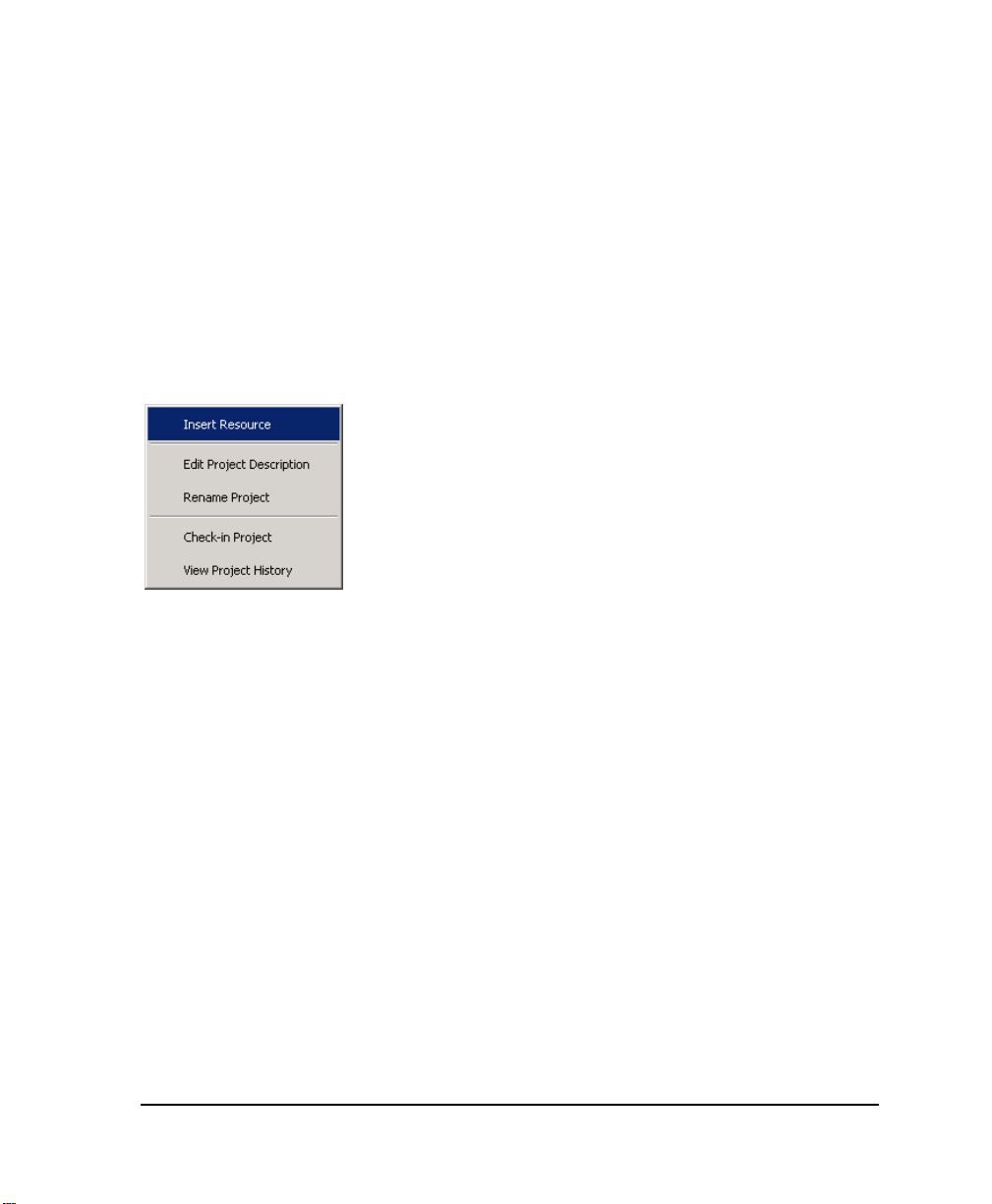
Contextual Menus
Contextual menus are displayed by right-clicking in the workspace of the various tools and
applications. From the Hardware Architecture view, you can access a contextual menu for
configurations or resources. For configurations, you access it by right-clicking a
configuration's title bars. For resources, you access it by clicking a resource’s name in the
configuration window. From the Link Architecture view, you can access a contextual menu for
resources by right-clicking a resource’s title bar.
Example
Status Bar
A status bar appears at the bottom of the main window displaying information about
commands, operations, and projects.
To show or hide the status bar
1. From the Options menu, choose Layout.
The Layout editor appears.
2. To show the status bar, check Status Bar then click OK.
3. To hide the status bar, uncheck Status Bar then click OK.
DS800 Development Suite 2.1 - Workbench 25
Page 46

Customization
You can choose to customize the colors and fonts for many aspects of the Workbench as well
as set working preferences. You can customize the colors and fonts for the following items:
For the dictionary, you can set the font and the colors used for text, scope, and instances
For the ST and IL editors, you can set the font and the colors used for background and
text (basic syntax)
For the FBD editor, you can set the font and the colors used for background, text,
connection and element outline lines, line shadows, and selected elements as well as the
fill for main elements
For the LD, FC, and SFC editors, you can set the font and the colors used for background
and text as well as the fill for main elements
For the FBD and LD editors, you can set the color for comments and for Boolean values
(TRUE and FALSE) displayed while in debug mode.
You can also set the colors for resource data links used with bindings.
You can set the following working preferences:
The number of recent project files to display in the File menu
Reload the last project at startup
Always prompt before saving changes to the project
To customize colors and fonts
Resetting the default for an item restores the colors and fonts to those when the Workbench
was installed.
1. From the Options menu, choose Customize.
26 DS800 Development Suite 2.1 - User Manual
Page 47

2. On the Customize editor, select the Colors and Fonts tab, then select the item to modify.
3. To change the font used, select a font and size. You can choose to bold the font.
4. To change the foreground or background colors, click the respective button, then from the
color editor, choose a pre-defined color or specify a custom color.
To set working preferences
1. From the Options menu, choose Customize.
2. On the Customize editor, select the Preferences tab.
DS800 Development Suite 2.1 - Workbench 27
Page 48

3. Make the desired changes.
28 DS800 Development Suite 2.1 - User Manual
Page 49

Directory Structure
The installation process creates the following directory structure:
Emerson Root directory for all
Emerson products
DS800 2.1 DS800 Workbench files
Bin Executable files
Simul Simulator target files
Tmp Temporary files
User User profile files
Projects Emerson projects
DS800 2.1 DS800 Workbench projects
Prj Projects
<project> Individual Project
Directories
<configuration> A directory per hardware
configuration
<resource A directory per resource
Tpl DS800 templates
EmptyLibmonoresource EmptyLibmonoresource
templates
<configuration> A directory per hardware
configuration
<resource> A directory per resource
DS800 Development Suite 2.1 - Workbench 29
Page 50

EmptyLibmultiresource EmptyLibmultiresource
templates
<configuration> A directory per hardware
configuration
<resource> A directory per resource
EmptyPrjmonoresource EmptyPrjmonoresource
templates
<configuration> A directory per hardware
configuration
<resource> A directory per resource
EmptyPrjmultiresource EmptyPrjmultiresource
templates
<configuration> A directory per hardware
configuration
<resource> A directory per resource
Libmonoresource Libmonoresource templates
<configuration> A directory per hardware
configuration
<resource> A directory per resource
Libmultiresource Libmultiresource templates
<configuration> A directory per hardware
configuration
<resource> A directory per resource
Prjmonoresource Prjmonoresource templates
<configuration> A directory per hardware
configuration
<resource> A directory per resource
30 DS800 Development Suite 2.1 - User Manual
Page 51

Prjmultiresource Prjmultiresource templates
<configuration> A directory per hardware
configuration
<resource> A directory per resource
Shared Common files shared by
Emerson products
Error Reporting Solobug files for use when
reporting errors on Emerson
products
Help 2.1 Online help files for
Emerson products
Sentinel Sentinel driver files for use
with hardware keys
Projects are stored in the Projects directory, as MS-Access database (.MDB) files:
<drive>:Emerson/Projects/DS800 2.1/Prj/<project name>/PRJLIBRARY.MDB
For details on the project architecture, see page 368.
Note: Existing projects can be manually moved or copied to the "tpl" directory to create new
project templates.
Example
The panel resource in the main configuration within the proj1 project is stored in the directory:
<drive>:Emerson/Projects/DS800 2.1/Prj/proj1/main/panel/
DS800 Development Suite 2.1 - Workbench 31
Page 52

Working with Projects
You can work with DS800 Development Suite projects in one of two project editing modes:
Normal
Single-resource
The normal mode provides access for a single user to all resources and POUs making up a
project. While in the normal mode, no other users can access the project or its resources. Before
opening a project in normal mode, multiple users can access the individual resources of the
project for editing purposes, i.e., single-resource editing mode. The single-resource mode
limits access for an individual user to one resource and its POUs. Other users can access other
resources of the same project.
Note: Make sure to build the complete project in normal mode before editing single resources.
Otherwise, a build while in single-resource mode may generate errors.
Only one user can access a resource at any given time; while in use, a resource remains locked
to all other users. For instance, when editing a project in normal mode, all resources making up
the project are automatically locked for your use except for those resources currently open in
single-resource mode. The currently open resources are displayed in the workspace but remain
locked. Locked resources appear gray with a lock symbol in their title bar.
32 DS800 Development Suite 2.1 - User Manual
Page 53

You can unlock resources currently open in single-resource mode by another user by selecting
the resource, then choosing Unlock Resource from the Tools menu.
Warning: The Unlock Resource option should only be used when necessary. When unlocking
resources currently opened by another user, make sure the remote Workbench is no longer
running.
The Workbench automatically assigns a user name to a project, when running on a network.
The user name is displayed in the status bar and in the access control properties of the
resources. The assigned user name depends on the editing mode:
In normal mode, the user name is always UserName.Administrator
In single-resource mode, the user name is the Windows login user name of the user
editing the resource
Resources currently opened by another user hold the name of that user in their properties.
In single-resource mode, a project is displayed in the link architecture view with the project
and resource identification in the title bar of the single resource. The hardware architecture
view and binding list are not available. In the dictionary view and the I/O wiring view, only the
variables and wiring defined for the resource are displayed. Variables bound to other resources
as well as types and defined words are in read-only mode. While in single-resource mode, you
can switch a project to debug or simulation mode.
DS800 Development Suite 2.1 - Workbench 33
Page 54

While in normal mode, you can perform the following tasks:
Creating Projects
Renaming Projects
Adding a Project Description
While in the normal or single-resource project editing mode, you can perform the following
tasks with limitations depending on the mode:
Opening and Closing Projects
Saving Projects
Printing Projects
You can also control access to projects.
Creating Projects
When you create projects, you use one of four templates:
SingleROC800, SingleROC800E, and SingleFB107, containing one resource in one
configuration
MultipleROC800E, containing two resources in two different configurations linked by an
Ethernet network. This template is not available for use with non-networked versions of
the Workbench.
The SingleROC800, SingleROC800E, and MultipleROC800E templates are all RAS device
target specific. The LibSingleROC800, LibMultipleROC800, and LibSingleFB107 templates
are available for use with librairies.
To create a new project
1. From the File menu, choose New Project <Ctrl+N>.
2. Enter the project name (max 128 characters).
34 DS800 Development Suite 2.1 - User Manual
Page 55

3. Enter comments (optional).
4. Choose a template.
5. Click OK.
The project is created using the chosen template and the link architecture view is displayed.
You can only open one project at any given time. When changes have been made to an open
project, you will automatically be prompted to save the changes before creating a new one.
DS800 Development Suite 2.1 - Workbench 35
Page 56

Opening and Closing Projects
In the Workbench, you can only open one project at any given time. If changes have been made
to an open project, the system automatically prompts you to save changes before closing a
project or opening another. You can open projects in one of two project editing modes: normal
and single-resource.
Project filenames are always PRJLIBRARY.MDB, the project directory name represents the
given project name. When you open a project or create a new project, the hardware architecture
view and the link architecture view are cleared. When a project has been relocated, you need
to redefine its links within the Workbench before opening it.
When opening a project in single-resource editing mode, you need to select the project, then
choose a resource from the list of resources defined for the project. In the list of resources,
resources appear with icons indicating their security state or non-availability:
Resource unavailable, currently open by another user
When the advanced options are installed on your computer, you can choose to open a project
without the advanced options features such as alarms and events, trends, field communications.
To open an existing project
1. From the File menu, choose Open.
The Open Project dialog box is displayed:
36 DS800 Development Suite 2.1 - User Manual
Page 57

2. Locate the required project file name.
3. Do one of the following:
To open the project in normal editing mode, click Open.
The project is open in the normal editing mode having access to all resources and POUs.
To open the project in single-resource editing mode, check Open in
single-resource mode, then click Open.
The Resource Selection window is displayed with all project resources showing their
security states or non-availability.
DS800 Development Suite 2.1 - Workbench 37
Page 58

4. From the list of available resources, select the resource to open, then click OK.
The project is open in the single-resource editing mode where only the selected resource
is editable.
To open a project using a command line
You can open projects in single-resource editing mode or in read-only mode using a
command line.
" To open the project in single-resource editing mode from a command line, use the
following syntax:
DPM.exe project_path -res resource_name
Note: For command lines, resource names are case sensitive. You can also use the resource
number to identify the resource.
When manually starting the Workbench, you may need to provide the location of the
Workbench project. The Workbench needs to be started in it's location directory. For
example:
"C:\Program Files\Emerson\DS800\Bin\DPM.exe" "C:\Emerson/Projects/
DS800/Prj/Project1" -res Lead
" To open the project in read-only mode from a command line, use the following syntax:
DPM.exe project_path -readonly
When manually starting the Workbench, you may need to provide the location of the
Workbench project. The Workbench needs to be started in it's location directory. For
example:
"C:\Program Files\Emerson\DS800\Bin\DPM.exe" "C:\Emerson/Projects/
DS800/Prj/Project1" -readonly
38 DS800 Development Suite 2.1 - User Manual
Page 59

Saving Projects
The project name is used to create a unique directory structure. Saving the project saves it in
the MS-Access database of the project root directory. Other files related to the project are also
updated in this directory structure. When editing a project in single-resource mode, changes are
only saved for the edited resource.
To save a project
" From the File menu, choose Save Project.
Note: When a project is saved, the undo/redo history is cleared.
Renaming Projects
You can rename projects and edit their comments. You cannot rename projects while in
single-resource editing mode. Before renaming projects, make sure to close all Workbench
windows such as language editors and browsing tools.
To rename a project
1. From the File menu, choose Rename Project.
The Rename Project dialog box appears:
2. Change the name and comment as required.
3. Click OK.
The directory structure containing the project is renamed when you save changes to the project.
DS800 Development Suite 2.1 - Workbench 39
Page 60

Adding a Project Description
You can include a text description for a project.
To edit the project description
" From the Tools menu, choose Edit Project Description.
Printing Projects
You can print projects using the Document Generator. For details on the Document Generator,
see page 337.
To print the current Project
" From the File menu, choose Print.
The document generator appears with a standard list of elements to be printed for a complete
project.
40 DS800 Development Suite 2.1 - User Manual
Page 61

Project Access Control
For project security, you can control access using a password. You can also apply the read-only
mode to the entire project. In read-only mode, users not having the password will have
read-only access to the project. When opening a project in read-only mode, all resources and
POUs making up the project are set to read-only mode. However, individual resources and
POUs making up projects can have their own access control. For instance, a resource having
its own password without the read-only option remains locked and cannot be viewed without
its password. While in read-only mode, you cannot build a project. When importing and
exporting projects having access control, password definitions are retained.
The DS800 Workbench enables monitoring a project, i.e., debugging as well as viewing
TLP variables and parameters when a project is opened with access control or in read-only
mode. You can open projects in read-only mode when opening the Workbench or open projects
in read-only mode using a command line. While in monitoring mode, a banner indicating this
mode is displayed above the status bar.
To set access control for a project
When a password is set for a project, you can choose to enable users not having the password
to open the project in read-only mode. The read-only mode for a project is applied to all
resources and POUs making up the project. However, individual resources and POUs may
have their own access control.
1. From the File menu, choose Project Properties.
The Project Properties Security editor is displayed.
DS800 Development Suite 2.1 - Workbench 41
Page 62

2. In the New field, enter the password for the project.
3. In the Confirm New field, reenter the password.
4. To enable users not having the password to open the project in read-only mode, check
Read Only.
42 DS800 Development Suite 2.1 - User Manual
Page 63

Importing and Exporting Workbench
Elements
You can import and export Workbench elements, i.e., projects, configurations, resources, and
POUs, from one project to another. When exporting an element, you copy the element from the
project and create a compressed exchange file (.PXF) holding all data except for spy lists and
step-by-step debug information. Therefore, enabling you to copy and paste elements from one
project to another. When importing and exporting elements having access control, password
definitions are retained.
To export a Workbench element
1. Depending on the element type, do one of the following steps:
For projects, from the File menu, choose Export, then Project.
For configurations, resources, and POUs, select the element (either from the link
architecture or hardware architecture view), from the File menu, choose Export,
then the element type.
2. In the Export window, select a directory in which to store the compressed exchange file,
then click Start.
3. To close the window when the export is complete, click Close.
To import a Workbench element
You can only import Workbench elements that have previously been exported and stored as
compressed exchange files. You cannot import elements having the same name as those in a
project. Before importing an element, you can choose to create an automatic backup of your
project.
1. From the File menu, choose Import, then Exchange File.
2. In the Import Exchange File window, select the Import from file option, then click Next.
3. Click Browse to locate the compressed exchange file (.PXF file), then click Next.
4. In the list at the top of the window, select the file name, then click Next.
DS800 Development Suite 2.1 - Workbench 43
Page 64

5. From the contents of the exchange file, select the element to import. For resources and
POUs, you also need to select the import destination.
6. Click Next.
7. Assign a name to the new element that will be created.
Note: Before importing elements, you should make a back-up copy of your project so that you
could restore it if the resulting import is unsatisfactory.
8. To create a backup copy of the project, check Create a backup copy of the project
before importing element.
The <prjlibrary.BAK> file is created in the project folder. If the results of the import are
unsatisfactory, you can choose to restore the project.
9. Click Next.
The element import begins.
10. When the import is complete, do one of the following:
To import another element from the exchange file, click Next.
To exit the dialog, click Close.
44 DS800 Development Suite 2.1 - User Manual
Page 65

To restore a project from a backup
1. Close the workbench.
2. Replace PrjLibrary.mdb with PrjLibrary.bak.
3. Remove (or rename) the <element_name> directory.
4. Rename <element_name.BAK> directory into <element_name> directory.
DS800 Development Suite 2.1 - Workbench 45
Page 66

Uploading Workbench Elements from
Targets
You can upload Workbench elements from any project into another when the resources’ code
has been stored on the target (if non-volatile storage exists for the platform). The element
source file is compressed and contains all data for the element. The file is in the same format,
compressed exchange file (.PXF), used when importing and exporting Workbench elements
from one project to another. For details on importing and exporting elements, see page 43.
Before uploading an element’s source file, you need to download its source code onto the
target. Furthermore, when setting up the resource’s Compilation Options properties, you need
to check the Embed Zip Source option and select the element type.
To upload an element from sources on a target
The element upload process consists of uploading the source file containing the element from
the target onto the local computer for access, then importing the element into the project from
the source file. Before importing an element from an uploaded source file, you can choose to
create an automatic backup for your project.
1. In the project, make sure that the configuration (in which to upload the element) is
connected to the correct network with the correct connection parameters (IP Address
for ETCP).
2. From the File menu, choose Import, then Exchange File.
3. In the Import Exchange File window, select the Upload from target option, then
click Next.
4. From the list of available configurations, select the configuration where the required
sources are located, then click Next.
5. From the list of available sources, select the one to upload, then click Next.
6. When the upload is complete, click Next.
46 DS800 Development Suite 2.1 - User Manual
Page 67

7. From the contents of the exchange file, select the element to import (for resources and
POUs, you also need to select the import destination), then click Next.
8. Assign a name to the new element that will be created.
Note: Before importing elements, you should make a back-up copy of your project so that you
could restore it if the resulting import is unsatisfactory.
9. To create a backup copy of the project, check Create a backup copy of the project
before importing element.
The <prjlibrary.BAK> file is created in the project folder. If the results of the import are
unsatisfactory, you can choose to restore the project.
10. Click Next.
The element import begins.
11. When the import is complete, do one of the following:
To import another element from the exchange file, click Next.
To exit the dialog, click Close.
DS800 Development Suite 2.1 - Workbench 47
Page 68

Link Architecture View
The link architecture view graphically displays the resources of a Project and the
resource data links between them. This is the default view of the Workbench providing a main
entry point to all editors. In the link architecture view, you manage many aspects of a project:
creating resources
linking resources (data links for bindings between resources)
defining variable groups
creating and manipulating POUs (Program Organization Units)
setting up I/O wiring
To access the link architecture view
" From the Window menu, choose project_name-Link Architecture.
Resources
Each resource is displayed as a separate window within the link architecture view. The
resource window title bar includes:
An icon indicating the operative state and security state of the resource
The resource name and comment
48 DS800 Development Suite 2.1 - User Manual
Page 69

A Windows control button to maximize or restore the resource window
A Data Link button enabling you to graphically create data links between resources
The operative state of a resource is indicated by the color of the upper triangle in the resource
icon:
Blue. The resource is in editing mode.
Green. The resource is in real-time mode (running), debug mode, or simulation
mode.
You can access the contextual menu from a resource by right-clicking in its title bar.
Double-clicking the title bar minimizes/restores a resource window.
You can also resize resource windows by placing the cursor over an edge or corner until it
shows double arrows and dragging:
Resource Window Workspace
The Workspace displays a graphical representation of the various components of each
resource.
+ Parameters
Variable Groups
Programs
DS800 Development Suite 2.1 - Workbench 49
Page 70

Functions
Function Blocks
To expand / collapse any branch of the hierarchy
" Click '+' ('-' to collapse).
Note: Selecting one of the components changes the menu items available on the menus of the
Workbench. For example, if a function is selected, the Insert menu includes the Add Function
option. The contextual menus are also affected by selections within the resource window.
Creating Resources
When you create resources in the link architecture view, these resources are automatically
assigned to the first configuration. You can also choose to create, i.e., insert resources directly
in configurations while in the hardware architecture view. After having created resources, you
can move them. For details on moving resources, see page 113.
To create a new resource
You can create resources using the main menu or a contextual menu, accessed by right-clicking
the empty area of the link architecture view’s workspace.
" From the Insert menu, choose Resource.
50 DS800 Development Suite 2.1 - User Manual
Page 71

Renaming Resources
You can rename an existing resource by editing its properties. When a resource is selected, the
Properties option is available from the main menu or a contextual menu. From the resource’s
Properties window, you can also edit the comments for the resource.
To rename a resource
1. Select the resource.
2. From the Edit menu, choose Properties.
The Resource Properties dialog box appears - on the General Tab.
3. Edit the resource name as required.
4. Edit the comment as required.
5. Click OK.
Copying Resources
You can copy a resource and place it on the clipboard. When copying resources, password
definitions are copied, whereas, step-by-step debug information is not copied. When copying
resources having The copy command is available from the main menu, the Ctrl+C keyboard
command, the main toolbar, or a contextual menu.
Note: Before copying, click in a blank area inside the resource window to deselect individual
programs or groups.
To copy a resource from the link architecture view
You can access the contextual menu by right-clicking the title bar of the resource.
1. Click on the title bar of the resource.
2. From the Edit menu, choose Copy.
DS800 Development Suite 2.1 - Workbench 51
Page 72

To copy a resource from the hardware architecture view
You can access the contextual menu by right-clicking the resource in the configuration
window.
1. Select the resource.
2. From the Edit menu, choose Copy.
Pasting Resources
You can paste a resource into the workspace of the link architecture view or into a
configuration, in the hardware architecture view. When pasting resources, password
definitions are also pasted, whereas, step-by-step debug information is not pasted. The paste
resources using the main menu, the Ctrl+V keyboard command, the main toolbar, or a
contextual menu.
To paste a resource in the link architecture view
You can access the contextual menu by right-clicking the title bar of the resource.
1. Click on an empty area of the link architecture view.
2. From the Edit menu, choose Paste Resource.
To paste a resource in the hardware architecture view
You can access the contextual menu by right-clicking the resource in the configuration
window.
1. Select a configuration to paste the resource into.
2. From the Edit menu, choose Paste Resource.
Note: Links coming from or arriving to a resource are not copied and pasted.
52 DS800 Development Suite 2.1 - User Manual
Page 73

Deleting Resources
You can delete a resource from the workspace of the link architecture view or from a
configuration, in the hardware architecture view. The delete command is available from the
main menu, the Delete keyboard command, the main toolbar, or a contextual menu.
Note: Before deleting, click in a blank area inside the resource window to deselect individual
programs or Groups.
To delete a resource
You can access the contextual menu by right-clicking the resource title bar.
1. Select the resource.
2. From the Edit menu, choose Delete.
DS800 Development Suite 2.1 - Workbench 53
Page 74

Editing Resource Properties
You need to define several properties at the resource level, intimately linked to targets (and
their implementation). These properties determine the behavior of the programs and hardware
such as the type of code generated, the timing, and Hardware specific properties.To access the
Resource Properties window
1. From the Window menu, choose project_name-Link Architecture.
2. Select a resource.
3. From the Edit menu, choose Properties.
The Resource Properties window is displayed.
54 DS800 Development Suite 2.1 - User Manual
Page 75

Resource Identification
The resource identification properties of a resource include its name, comments, and a resource
identification number. The resource number is automatically assigned. You can choose to
change this number. However, when changing this number, you need to assign a number that
is unique within the project. The resource number identifies the Virtual Machine that will run
the resource code. Comments appear in the resource’s title bar, next to its name.
You define resource identification properties on the General tab of the Resource Properties
window:
Compilation Options
The compilation options of a resource define many aspects of a resource’s run-time and
simulation options:
The target operating system on which the resource will run
The generation of debug information
The type of code to generate and compiler options
The symbol table
DS800 Development Suite 2.1 - Workbench 55
Page 76

Embedded zip of the source files
You can also choose the target type at the configuration level. However, changing the target
for a configuration affects all resources attached to it. For details on configuration properties,
see page 114.
You specify a resource’s compilation options on the Target/Code tab of the Resources
Properties window:
Generate Debug Information
When using the step-by-step mode, for debugging purposes, you need to generate debug
information for a resource and its ST, IL, and LD POUs. For details on step-by-step mode, see
page 299. When setting up debug information, you also need to specify the individual POUs
for which to generate debug information. Debug information includes call stack information
which tracks stepping between POUs and called functions. You can only generate debug
information for resources producing TIC code.
Note: The first time you choose to generate debug information for a resource, the complete
resource is compiled when you build the resource. Subsequently, when you add or remove
individual POUs, only those POUs are compiled when you build the project.
56 DS800 Development Suite 2.1 - User Manual
Page 77

To generate debug information for ST, IL, and LD programs
1. To generate call stack information for use while stepping in POUs, check Generate
debug information.
2. To generate debug information, click .
3. In the Debug Information window, check individual POUs, select all POUs, or unselect
all POUs, then click OK.
Target Code and Compiler Options
You can specify the generation of three types of code for use in simulation or run time:
Code for simulation, code required when running the application in simulation. To run
the Simulator, you must check Code for Simulation to produce the application code.
TIC Code, the indication of whether Target Independent Code is produced by the
compiler. TIC code can be executed on DS800 Development Suite virtual machines.
Structured C source code, the indication of whether structured C source code is produced
by the compiler. Structured C source code can then be compiled and linked with DS800
Development Suite libraries to produce embedded executable code.
You can also define compiler options for individual resources. For details on compiler options,
see page 349.
DS800 Development Suite 2.1 - Workbench 57
Page 78

Symbol Table
You can specify whether to download the symbol table to the Virtual Machine with the
resource code. The symbol table groups the variable names of the resource. You can also
choose to download the complete symbol table or the reduced symbol table.
Note: The Complete Table must be selected. The reduced symbol table contains only names
of variables for which the 'Address' cell had been completed. For details on the variables grid,
see page 142.
To change the Build Symbol Table
1. Click Options.
The Build Symbol Table dialog box appears.
2. Choose the type of symbol table to download.
Embed Zip Source
You can embed, on the target, an exchange file (.PXF) holding all data from Workbench
elements. This exchange file is the same as the file created when exporting an element.
58 DS800 Development Suite 2.1 - User Manual
Page 79

Run-time Settings
The run-time settings include the cyclic and behavior definitions of a resource when the
resource is executed. For information about execution rules, see page 376.
You specify a resource’s run-time settings on the Settings tab of the Resources Properties
window:
Trigger cycles, enables you to specify the cycle timing, i.e., the amount of time given to
each cycle. If a cycle is completed within the cycle time, the system waits until the cycle
time has elapsed before starting a new cycle. The cycle consists of scanning the physical
inputs of the process to drive, executing the POUs of the Workbench resource, then
updating physical outputs. The virtual machine executes the resource code according to
the execution rules. For details about the execution rules, see page 376.
Detect errors, enables the storing of errors. You need to define the number of entries, i.e.,
the size of the queue (FIFO) in which detected errors are stored.
Cycle to Cycle / Real Time, indicates whether programs are executed during the cycle or
not. For Cycle to Cycle, inputs are read but the code is not executed during the cycle
time. This option is useful for testing I/Os.
Memory for Retain, indicates the location where retained values are stored (the required
syntax depends on the implementation)
DS800 Development Suite 2.1 - Workbench 59
Page 80

You can also specify advanced settings for resources:
SFC dynamic behavior limits
Memory size for online changes
To access advanced settings
" Click Advanced.
SFC Dynamic Behavior Limits
The SFC dynamic behavior limits determine the amount of memory, allocated by the target at
initialization time, to manage SFC dynamic behavior (i.e. token moving). The amount of
allocated memory is calculated as a linear relation with the number of SFC POUs:
Alloc Mem (bytes) = N * NbElmt * sizeof(typVa)
NbElmt = GainFactor * NbOfSFC + OffsetFactor
Where:
N = 5 (constant linked to SFC engine design)
typVa = 16 bits in the medium memory model (32 bits in the large memory model)
NbElmt represents for each executed cycle:
The maximum number of transitions that can be valid. That is to say transitions with at
least one of their previous steps being active.
60 DS800 Development Suite 2.1 - User Manual
Page 81

A simpler, but more approximate definition is:
The maximum number of steps that can be active.
The maximum number of actions that can be executed.
Here, an action refers to an N, P1 or P0 action linked to a step.
If the available memory is not enough at a specific moment:
If the target is generated with check mode (ITGTDEF_SFCEVOCHECK defined in
dsys0def.h), The target kernel generates a warning to signal an SFC token moving error
or an action execution error and the resource is set in ERROR mode (i.e. cycles are no
longer executed). Otherwise, kernel behavior may be unpredictable.
Memory Size for Online Changes
The memory size for online changes defines the amount of memory that is reserved on the PLC
for managing online changes:
Code Size, the amount of memory reserved for code sequence changes
User Variable Size, the amount of memory reserved for adding variables data. When
generating symbol monitoring information for a POU, the same amount of memory is
also reserved for the POU.
When performing downloads and online changes, parts of the User Variable Size memory
space is used to store project data such as variables values. This memory space becomes
free when you clean the project.
DS800 Development Suite 2.1 - Workbench 61
Page 82

Resource Network Parameters
You need to define network parameters attached to the resource for each available network.
You specify a resource’s network parameters on the Network tab of the Resources Properties
window:
Note: The parameters appearing in the list reflect those attached to the resource. Some
parameters are read-only. However, when a resource is attached to a network not requiring
parameters, the list appears empty.
You can also access the online help by clicking Help.
For the HSD network, the current definition is the following:
The consumer computes the time elapsed between production and consumption and tests if it
less than the 'ValidityTime' parameter specified for the producer resource in the workbench.
The user must be careful when specifying this value to take into account the cycle time of the
producer resource. This resource cannot emit values at a period shorter that its cycle time.
If this time-out is detected, the consumer sets the error variable to
ISA_HSD_KVB_ER_TIMEOUT value.
62 DS800 Development Suite 2.1 - User Manual
Page 83

For the ETCP network, the current definition is the following:
On the consumer side, if no data is received during the time specified in the Timeout parameter
value, then the error variable is set to ETCP_KVB_ERR_TIMEOUT value.
Custom Resource Parameters
You can define specific OEM options for a resource that may be implemented in your target.
Note: DS800 Development Suite standard targets do not have extended parameters. Contact
your target supplier for specific details.
DS800 Development Suite 2.1 - Workbench 63
Page 84

Resource Access Control
For resource security, you can control access using a password and you can choose to apply the
read-only mode to an entire resource. When resources are password-protected, users not
having the password can change resource properties, wire and bind variables, modify the
memory for retain, and add devices to wired variables. POUs in a resource can have their own
level of access control. For instance, a POU having its own password remains locked and
cannot be viewed without entering its password. However, a POU using its resource’s
password also inherits the resource’s security properties such as the read-only attribute.
The security state of a resource is indicated by the color of the lower triangle in the resource
title bar icon. The resource can also be currently opened by another user.
Resource
Icon
Note: While in debug mode or performing builds, unlocked resources as well as resources
having no access control switch to read-only mode. Locked resources remain locked.
For projects having read-only access control, the resources and POUs making up the project
are also set to the read-only mode except for those having individual access control.
Security
State
Gray. The resource has no access control. All users have read and write access
in the resource. POUs in the resource may have individual access control.
Red. The resource is locked. Users not having the resource password cannot
access the resource or its POUs; these users do not have read or write
capabilities. These users can change resource properties, wire and bind
variables, modify the memory for retain, and add devices to wired variables.
Cyan. The resource is in read-only mode. Users not having the resource
password can view the resource and its POUs; these users only have read
capabilities. These users can change resource properties, wire and bind
variables, modify the memory for retain, and add devices to wired variables.
POUs in the resource may have individual access control.
Green. The resource is unlocked. User can access the resource and its POUs;
this user has read and write capabilities. However, POUs in the resource may
have individual access control.
The resource is currently opened by another user in single-resource project
editing mode. User can only access the resource properties in read-only mode.
64 DS800 Development Suite 2.1 - User Manual
Page 85

When copying, pasting, importing, and exporting resources having access control, password
definitions are retained.
When editing a project, resources making up the project are automatically locked by you
except for those resources where another user set password protection or that are currently in
use by another user in the single resource editing mode.
To set access control for a resource
You set access control for a resource in its properties’ Security tab.
1. Specify a password:
To use an unique password, in the New field, enter a password then reenter it in the
Confirm New field.
To use the same password as set for the project, check Use Project Password.
2. To enable all users to access the resource in read-only mode, check Read Only.
DS800 Development Suite 2.1 - Workbench 65
Page 86

To unlock a resource
When entering a password while in debug mode or performing a build, the resource is only
unlocked after stopping the debug mode or when the build is completed.
1. Right-click the resource’s title bar, then from the contextual menu, choose
Enter Password.
2. In the Security dialog box, enter the password for the resource.
The resource is unlocked.
Resource Description
You can include a free-format text description for a resource.
To edit the resource description
1. Select the resource.
2. From the Tools menu, choose Edit Description.
3. Edit the description as required.
66 DS800 Development Suite 2.1 - User Manual
Page 87

Variable Bindings
Bindings are directional links, i.e., access paths, between variables located in different
resources. One variable is referred to as the producing variable and the other as the consuming
variable. The value stored in the producing variable is transferred to the consuming variable.
The Workbench enables two types of bindings: internal bindings and external bindings.
Internal bindings are between resources within the same project. External bindings are between
resources belonging to different projects.
Note: Online changes are possible as long as internal and external binding definitions remain
the same.
Binding the variable V1 from resource R1 to the variable V2 of resource R2 means that V1 is
periodically copied to V2 using memory sharing or network exchanges.
Variables coming from bindings (consumed variables) are refreshed in the resource at the
beginning of the cycle, each time the producing resource sends them, i.e. on each end of the
producing resource cycle.
The variable is not updated in the consuming resource until the producing resource sends them
through the binding media. For example:
Producer
Binding
Consumer
No update of the variable on that cycle
DS800 Development Suite does not impose the read-only accessibility for consumed
variables. However, it is highly recommended to declare consumed variables with
read-only attribute in order to avoid conflicts between Binding and execution of POUs.
DS800 Development Suite 2.1 - Workbench 67
Page 88

This behavior is applied in both HSD and ETCP Binding drivers. This behavior may change
when using other network drivers implemented according to different conventions.
Binding error variables
Binding error variables enable the management of binding errors at the consumer resource
level; one error variable for one consumer resource for each resource that produces to this
resource. The virtual machine gives specific values to these error variables.
Note: DS800 does not support producer error variables.
Example
Production errors
The variable 'A' of the R1 resource represents the
producer error variable for all binding links
starting from R1 and using the HSD driver
(in the example only link from R1 to R3).
The variable 'B' of the R1 resource represents the
producer error variable for all all binding links
starting from R1 and using the ETCP network
(links from R1 to R4 and from R1 to R5).
Consumption errors
The variable 'F' of the R5 resource represents the
consumer error variable for the unique binding link
that comes from R1 and using ETCP.
The variable 'G' of the R5 resource represents the
consumer error variable for the unique binding link
that comes from R2 and using ETCP.
Depending on the driver used the error variables can take different values with different
meanings.
68 DS800 Development Suite 2.1 - User Manual
Page 89

Warning: Once the error variable is set to a non-zero value, it has to be reset to 0 by user or
by Programs.
To test globally that there is a binding error, you can test the value of the following system
variables:
__SYSVA_KVBPERR: for a production error. It is a Boolean variable. If it is true it
means there is a production error. DS800 does not support the __SYSVA_KVBPERR
system variable.
__SYSVA_KVBCERR: for a consumption error. It is a Boolean variable. If it is true it
means there is a consumption error.
For HSD:
To test values of one binding error variable, you should create the following defined words in
the dictionary of your project:
The 0 value in the error variable indicates there is no error.
ISA_HSD_KVB_ER_MUTEX 1 An error occurred with semaphore management
ISA_HSD_KVB_ER_SPACE 2 An error occurred with memory space access
ISA_HSD_KVB_ER_NOKERNEL 3 The bound producer is stopped (not running).
This error happens only for consumer resources.
ISA_HSD_KVB_ER_TIMEOUT 4 Variable was not refreshed within the maximum
time allowed (ValidityTime). This error happens
only for consumer resources.
ISA_HSD_KVB_ER_BAD_CRC 5 Producer and consumer have different CRC.
ISA_HSD_KVB_ER_INTERNAL 6 Internal error
DS800 Development Suite 2.1 - Workbench 69
Page 90

For ETCP:
To test values of binding error variables, you should create the following defined words in the
dictionary of your Project:
A value of 0 in the error variable indicates no error.
ETCP_KVB_ERR_BINDING_IN_PROCESS 1 The binding initialization process is
on its way.
ETCP_KVB_ERR_NO_PRODUCER 2 The remote producer is not currently
runnin g. This error happens only for
consumer resources.
ETCP_KVB_ERR_BAD_CRC 3 Producer and consumer have different
CRC.
Obsolete error value 4 The producer has been stopped. This
error happens only for consumer
resources.
ETCP_KVB_ERR_DATA_DIFFUSSION 5 Error during diffusion process.
ETCP_KVB_ERR_TIMEOUT 6 ETCP server does not answer quickly
enough (TimeOut). This error happens
only for consumer resources.
ETCP_KVB_ERR_IMPOSSIBLE_TO_BIND 7 Impossible to bind.
70 DS800 Development Suite 2.1 - User Manual
Page 91

Internal Bindings
Internal variable bindings are bindings between variables of resources belonging to the same
project. Before creating internal bindings for variables, you need to link the resources holding
them using data links.
You manage resource data links and internal variable bindings in the Bindings List window.
You can also manage resource links directly from the link architecture view.
The Bindings window displays the resource links and internal variable bindings defined for a
project. The window is divided into three parts:
The Resource-binding grid
The Variable-binding grid
The Binding List window toolbar
To access the Binding List window
1. From the Window menu, choose project_name-Link Architecture.
The link architecture view appears displaying existing resources and their data links.
2. Do one of the following:
Click .
Double-click a data link joining two resources.
DS800 Development Suite 2.1 - Workbench 71
Page 92
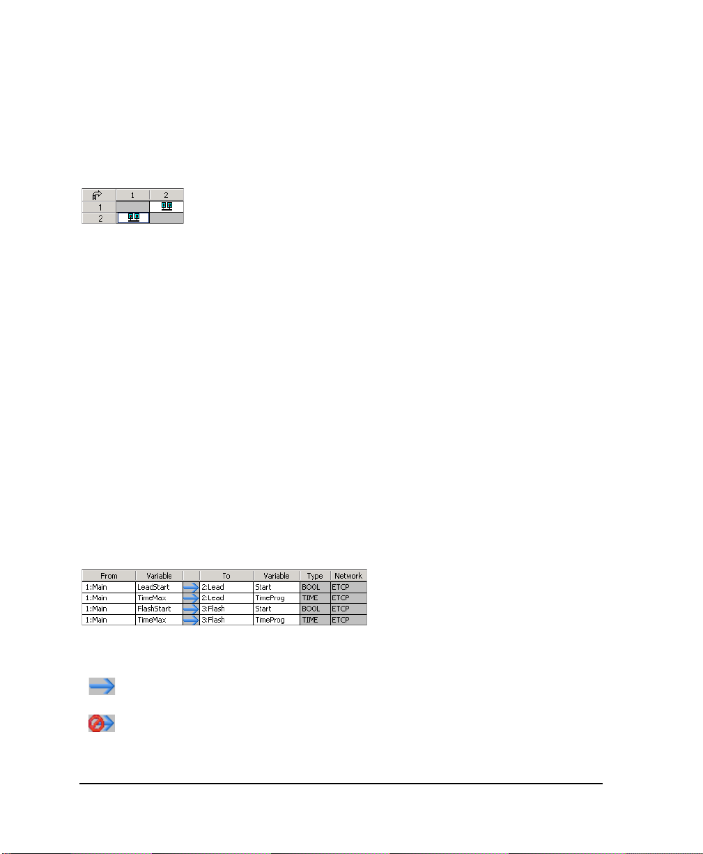
Resource-binding Grid
The Resource-binding grid, on the left side of the Binding List window, displays the data links
between resources. The first column and the top row display the available resource’s numbers.
The resource display order depends on their configuration numbers.
When working in the Resource-binding grid, you can perform various tasks using the mouse
or keyboard commands:
Description Mouse Keyboard
Move into the grid Select cells Arrows keys
Select an entire row Select a row header Shift+space bar
Select an entire column Select a column header Ctrl+space bar
Select the entire grid Select an arrow on the top left of the grid Shift+Ctrl+space bar
Switch to the
Variable-binding grid
Variable-binding grid
The Variable-binding grid, on the right side of the window, enables you to manage variable
bindings. The variable-binding grid manages the bindings between variables. The grid shows
where a binding comes from and where it goes to, the type of the variable, and the network used
for communicating.
Click on the Variable-binding grid Tab
The column between the variable information indicates the status of the binding:
The binding does not have parameters and the status is OK
The binding does not have parameters but the status is bad
72 DS800 Development Suite 2.1 - User Manual
Page 93

The binding has parameters and the status is OK
The binding has parameters but the status is bad
A bad status occurs when the types, string sizes, or dimensions of variables don't correspond
or if the network, used for the binding, doesn't exist.
When working in the Variable-binding grid, you can perform various tasks using the mouse or
keyboard commands:
Description Mouse Keyboard
Move into the grid Select cells Arrows keys
Switch to the
Resource-binding grid
Binding List Toolbar
The Binding List window toolbar enables you to perform many resource link and variable
binding operations:
Hides the resource-binding grid
Accesses the online help
Click in the Resource-binding grid Tab
Creates a new binding variable
Edits an existing binding variable. This operation is only
available for use in the variable-binding grid.
Deletes selected cells, rows, or columns
Note: If the two resources are distant, they must be located in configurations that are attached
to the same target. Heterogeneous bindings are not yet supported.
DS800 Development Suite 2.1 - Workbench 73
Page 94

Linking Resources
You need to link resources before binding variables belonging to them. Data links between
resources are directional. All bindings using a data link must use the same network. You can
link resources from the Binding List window. You can also link resources from the link
architecture view.
In the Resource-binding grid, you create links between resources by locating the resource
holding the producing variable in the first column and the resource holding the consuming
variable in the top row, then selecting the grid cell where both meet.
In the grid, resource links appear as one of two types:
The linked resources belong to the same configuration
The linked resources belong to different configurations
In the link architecture view, you create links by physically joining the resource holding the
producing variable with the resource holding the consuming variable. In this view, data links
appear as directional arrows linking the resources. The color of data links depend on the type
of bindings using it:
Black The data link is only used for internal bindings
Blue The data link is used for internal bindings
When bindings have an error, the symbol is displayed on the data link used by the binding.
74 DS800 Development Suite 2.1 - User Manual
Page 95

You can customize the colors of resource data links.
To link resources from the Binding List window
You can access the Binding list window from the main menu or the Windows toolbar.
1. From the Project menu, choose Binding List.
The Binding List window appears.
2. In the first column of the Resource-binding grid, locate the resource number of the
resource holding the producing variable.
3. In the top row of the Resource-binding grid, locate the resource number of the resource
holding the consuming variable.
4. Double-click the grid cell where both resource numbers meet.
An icon appears in the grid cell indicating whether the link is between resources from the same
or different configurations.
To link resources from the link architecture view
1. On the resource holding the producing variable, click and hold the Data Link
button , located on its title bar.
2. Drag the link to the resource holding the consuming variable.
3. Release the mouse button.
The data link is displayed graphically.
DS800 Development Suite 2.1 - Workbench 75
Page 96

Deleting Resource Links
You can delete links between resources, i.e., data links, from within the Binding list window.
You can also delete links from the link architecture view.
Note: Deleting a resource link also deletes the variable bindings using it.
To delete a resource link from the Binding List window
1. In the Resource-binding grid, select the grid cell holding the resource link to delete.
2. Do one of the following:
From the Binding List window’s toolbar, click .
Press Delete.
The grid cell appears blank.
To delete a resource link from the link architecture view
1. In the link architecture view, click on the resource link.
The selected data link appears hightlighted:
2. Do one of the following:
From the Edit menu, choose Delete.
Press Delete.
76 DS800 Development Suite 2.1 - User Manual
Page 97

Viewing the Internal Bindings Defined for Resources
You can view all producing variable bindings or all consuming variables defined for a resource
at the same time. You can also choose to view all bindings defined for all resources, i.e., the
entire project. However, when viewing bindings, you cannot edit their definitions.
To view the producing variable bindings for a resource
" In the first column of the Resource-binding grid, click the corresponding resource
number.
To view the consuming variable bindings for a resource
" In the top row of the Resource-binding grid, click the corresponding resource number.
To view the bindings defined for a project
" In the Resource-binding grid, click .
Hiding and Showing Resource Links
In the link architecture view, you can choose to show or hide the data links between resources.
In hidden mode, links cannot be activated or selected. Links appear as short arrows, indicating
their direction, sticking out from the top right corner of resources:
To hide or show data links
You can hide or show data links using the main menu or the Options toolbar.
" From the Options menu, choose Hide/Show Links.
DS800 Development Suite 2.1 - Workbench 77
Page 98

Defining Internal Variable Bindings
Before defining bindings between variables, you must first link the resources to which they
belong. For bindings, one variable is known as the producing variable and the other as the
consuming variable.
You can only define bindings between variables of a same type. Producing variables can have
any direction attribute, i.e., input, output, and internal. Whereas, consuming variables can only
have the output or internal attribute and must also have the Free attribute.
You instantiate variable bindings in the Variable-binding grid of the Binding List window.
You define variable bindings in the Binding editor. When defining a binding, you need to
indicate a producing variable and a consuming variable, and the network used for
communicating. The producing variable serves as input for the binding. Whereas, the
consuming variable serves as output. You can choose to specify a default value to use in the
event of a communication error. You can also choose to specify a binding error variable
(producer error variables are not supported in DS800).
78 DS800 Development Suite 2.1 - User Manual
Page 99

The Producing Variable selection list contains all variables of the producer resource. The
Consuming Variable selection list contains all variables which do not have the INPUT
direction and are not already used as a consumed variable in an existing binding.
The network selection list contains the networks that are supported by the target of the
configuration of the first resource and the target of the configuration of the second resource.
The Binding Parameters list displays the parameters to be defined for the variables bound on
the selected network. This list may be empty depending on the network used by the binding.
For example: ETCP does not need any parameters at this level. You define parameters by
double-clicking on a parameter line to display the Binding Parameter dialog box (available
only when the parameter is editable). Some parameters are read-only.
The Binding Error Variables section contains two selection lists for selecting a variable (Global
/ Memory of the DINT type) in each resource to receive binding error values (producer error
variables are not supported in DS800). Producer error variables and consumer error variables
can be used in the resource's POUs to trap and act upon errors. The default value is None.
To create a binding between variables
1. In the Variable-binding grid, select the next available field.
2. From the Binding List window’s toolbar, click .
The Binding editor appears.
3. In the Producing Variable field, select the producing variable.
4. In the Consuming Variable field, select the consuming variable.
5. In the Network field, select the network used for communicating.
6. To set a default value for use in the event of a communication error, select
Use Default Value, then enter a value in the field.
7. To use a binding error variable, indicate it in the Binding Error Variables section
(producer error variables are not supported in DS800).
8. Click OK.
DS800 Development Suite 2.1 - Workbench 79
Page 100

Editing Internal Variable Bindings
You can change the contents of existing variable bindings. You edit bindings from the
Variables-binding grid of the Binding List window.
To edit the contents of an existing binding
1. In the Variable-binding grid, select the variable binding.
2. From the Bindings List window’s toolbar, click .
The Binding editor appears.
3. Make the necessary changes, then click OK.
Deleting Internal Variable Bindings
You delete variable bindings from the variable-binding grid of the Bindings List window.
To delete a variable binding
1. In the Variable-binding grid, select the variable binding.
2. Do one of the following:
From the Binding List window’s toolbar, click .
Press Delete.
80 DS800 Development Suite 2.1 - User Manual
 Loading...