

Page 1

Remote Automation Solutions
Part Number D301813X012
QER 17Q001
January 2017
DP – Prognosis™ FC User Manual (for
ROC800-Series)
Page 2

DP – Prognosis FC User Manual (for ROC800-Series)
ii Issued January-2017
Revision Tracking Sheet
January 2017
This manual may be revised periodically to incorporate new or updated information. The revision date
of each page appears at the bottom of the page opposite the page number. A change in revision date
to any page also changes the date of the manual that appears on the front cover. Listed below is the
revision date of each page (if applicable):
Page
Revision
Initial release
January-2017
Page 3

DP – Prognosis FC User Manual (for ROC800-Series)
Issued January-2017 Contents iii
Contents
Chapter 1 – Introduction 1
1.1 Scope and Organization ..................................................................................................................... 1
1.2 Product Overview ............................................................................................................................... 2
1.2.1 Theory of Operation ............................................................................................................. 2
1.2.2 Practical Application ............................................................................................................. 4
1.2.3 Operational Benefits ............................................................................................................ 4
1.3 Program Features .............................................................................................................................. 4
1.3.1 DP – Prognosis FC for up to 12 Meter runs ......................................................................... 4
1.3.2 Three Supported Meter Types ............................................................................................. 4
1.3.3 Customary Seven Diagnostics ............................................................................................. 4
1.3.4 Support for Stacked DPs ..................................................................................................... 5
1.3.5 Supports two or three measured DPs .................................................................................. 5
1.3.6 Adjustable Diagnostic Frequency ........................................................................................ 5
1.3.7 Multi-pass Averaging ........................................................................................................... 5
1.3.8 Pattern Matching .................................................................................................................. 5
1.4 Program Requirements ...................................................................................................................... 5
1.4.1 License Key.......................................................................................................................... 6
Chapter 2 – Installation 7
2.1 Installing the License Key .................................................................................................................. 7
2.1.1 Verifying the License Key Installation .................................................................................. 8
2.2 Downloading the Program .................................................................................................................. 8
2.3 MPU Loading Threshold .................................................................................................................. 12
Chapter 3 – Configuration 15
3.1 Results ............................................................................................................................................. 17
3.2 Configuration .................................................................................................................................... 20
3.3 Advanced ......................................................................................................................................... 24
3.4 Intermediate ..................................................................................................................................... 26
3.5 Detail ................................................................................................................................................ 30
3.6 Saving the Configuration .................................................................................................................. 33
Chapter 4 – Reference 35
4.1 Point Type 220: DP – Prognosis FC Parameters ............................................................................ 36
4.2 Program Status Codes and Messages ............................................................................................ 61
4.3 Pattern Match Codes and Messages ............................................................................................... 63
4.4 Zeroing the meter for Prognosis FC ................................................................................................. 66
Page 4

DP – Prognosis FC User Manual (for ROC800-Series)
iv Contents Issued January-2017
[This page is intentionally left blank.]
Page 5

DP – Prognosis FC User Manual (for ROC800-Series)
Issued January-2017 Introduction 1
Chapter 1 – Introduction
Caution
When implementing control using this product, observe best industry
practices as suggested by applicable and appropriate environmental,
health, and safety organizations. While this product can be used as a
safety component in a system, it is NOT intended or designed to be the
ONLY safety mechanism in that system.
This chapter describes the structure of this manual and an overview of
the DP – Prognosis™ FC program for the ROC800-Series Remote
Operations Controller (ROC800).
1.1 Scope and Organization
This document serves as the user manual for the DP – Prognosis FC
program, which is intended for use in the ROC800-Series Remote
Operations Controllers (ROC800).
This manual describes how to download and configure this program
(referred to as the “DP – Prognosis FC program” or “the program”
throughout the rest of this manual). You access and configure this
program using ROCLINK™ 800 Configuration Software (version 2.41
or greater) loaded on a personal computer (PC) running Windows® 7
(32 or 64-bit).
The sections in this manual provide information in a sequence
appropriate for first-time users. Once you become familiar with the
procedures and the software running in ROC800, the manual becomes a
reference tool.
This manual has the following major sections:
Chapter 1 – Introduction
Chapter 2 – Installation
Chapter 3 – Configuration
Chapter 4 – Reference
This manual assumes that you are familiar with the ROC800 and its
configuration. For more information, refer to the following manuals:
ROC800 Remote Operations Controller Instruction Manual (part
D301217X012)
ROCLINK 800
™
Configuration Software User Manual (for
ROC800-Series) (part D301250X012)
Page 6

DP – Prognosis FC User Manual (for ROC800-Series)
2 Introduction Issued January-2017
1.2 Product Overview
The DP – Prognosis FC program is used to verify the operation of a
differential pressure (DP) meter element and its differential pressure
instrumentation. The program is designed to work with Orifice Meters,
Venturi meters or Cone meters.
1.2.1 Theory of Operation
A DP meter uses a geometric constriction to produce momentum change
in a flow. Figure 1-1 shows an orifice meter and the associated pressure
profile in the pipe.
Figure 1-1. Traditional orifice meter pressure profile
Applying mass and energy conservation equations between pipe cross
sections upstream and in the vicinity of the constriction produces a flow
rate equation dependent on geometry, fluid density and DP.
Traditionally, the differential pressure is measured between a point
upstream of the restriction and the point of lowest pressure (vena
contracta). Flow calculations are performed using this differential
pressure value.
It has been shown that the constriction in a DP meter element actually
produces three predictable and repeatable pressure changes in the flow
stream. The Traditional DP (∆Pt) – mentioned previously - is measured
across the restriction. The Recovery DP (∆P
rec
) can be measured
between the downstream tap and a far downstream tap (~6 diameters
downstream for an orifice meter). The Permanent DP (∆P
ppl
) is
measured between the upstream pressure tap and the far downstream
tap. Figure 1-2 shows how these three values can be observed.
Page 7

DP – Prognosis FC User Manual (for ROC800-Series)
Issued January-2017 Introduction 3
Figure 1-2. Three differential pressures for the DP meter
The DP – Prognosis FC approach involves:
Measuring all three DPs at the meter element (optionally, two of the
DPs can be measured and one can be inferred, but this produces less
reliable results).
Performing flow calculations for all three meters.
Comparing the flow rates of the three meters – producing three
diagnostic values (diagnostics).
Comparing the pressure loss ratios of the three DPs to theoretical
values for pressure loss ratios – producing three diagnostic values
(diagnostics).
Comparing the numerical values of the three DPs for consistency
(∆Pt = ∆P
rec
+ ∆P
ppl
).
As can be seen, this results in seven different uncertainty parameters –
referred to as diagnostics. Customarily, the seven diagnostics are each
compared to allowable uncertainty setpoints – thereby converting the
values to dimensionless form. For instance,
Calculated traditional flow rate = 10.100
Calculated permanent flow rate = 10.800
Percent Difference = 100 * (10.800 – 10.100) / 10.100 = 6.93%
If the allowable percentage for this difference was configured to 2%,
then the dimensionless value of the first diagnostic (x1) would be:
6.93% / 2% = 3.47
In dimensionless form, any value between -1.0 and 1.0 is considered to
be indicative of a properly-performing meter.
Page 8

DP – Prognosis FC User Manual (for ROC800-Series)
4 Introduction Issued January-2017
1.2.2 Practical Application
The DP – Prognosis FC approach can be used to monitor the operation
of a DP meter with the intent of identifying uncertainty in the traditional
calculated measurement. Using the DP diagnostic approach, the
following conditions have been identified in orifice meters:
Orifice plate installed backwards
Damaged orifice plate (worn sharp edge, warped plate, dirty plate)
Obstructed flow in meter tube or through orifice
Physical plate or meter tube size different from values configured in
flow computer
Plugged or leaking transmitter impulse line
Transmitter calibration error
Transmitter calibration drift
Equalizing valve on instrument manifold leaking
Wet gas
1.2.3 Operational Benefits
The DP – Prognosis FC operating at a meter installation, the meter can
be managed by exception. Routine, scheduled inspection/calibration
procedures can be modified such that technicians address known
measurement problems immediately when exceptions are noted – rather
than waiting until the problem is discovered during the next scheduled
inspection. Furthermore, the time of onset of the exception can be
precisely identified – assisting in proper correction to flow data.
Common operating mistakes (installing plate backwards, changing plate
without changing flow computer configuration) are quickly identified
and clarified when DP diagnostics is running in the Flow Computer.
1.3 Program Features
1.3.1 DP – Prognosis FC for up to 12 Meter runs
The single license enables the Prognosis feature for all meters on the
ROC800.
1.3.2 Three Supported Meter Types
The program works with Orifice, Venturi, and Cone meters.
1.3.3 Customary Seven Diagnostics
The program produces the customary seven diagnostic values.
Page 9

DP – Prognosis FC User Manual (for ROC800-Series)
Issued January-2017 Introduction 5
1.3.4 Support for Stacked DPs
The program supports use of stacked DP instruments for Recovery and
for Permanent DP instruments
1.3.5 Supports two or three measured DPs
Although it is not recommended, the program can function using just
one additional DP instrument (plus the traditional DP). When either the
Recovery DP or the Permanent DP instruments are not configured, the
value of the unmeasured DP will be calculated from the other two DPs.
1.3.6 Adjustable Diagnostic Frequency
The diagnostic calculations can be run at a frequency ranging from once
per second to once per 255 days.
When main processor loading is a concern, the frequency of the
calculation can be reduced to alleviate processor loading.
1.3.7 Multi-pass Averaging
The program can be configured to perform multiple calculation cycles
and use the resulting average value of the seven diagnostics. This
feature can be used when there is high latency in DP measured values or
when wet gas is expected – to reduce nuisance alerts.
1.3.8 Pattern Matching
After the seven diagnostic values are calculated, the relationship of
these values to each other is compared with known pattern signatures.
This results in a pattern match code and text message which can provide
insight as to the particular problem – if any – with the meter.
1.4 Program Requirements
The DP – Prognosis FC program is compatible with version 3.61 (or
greater) of the ROC800 firmware or version 1.60 (or greater) of ROC800L
with version 2.41 (or greater) of the ROCLINK 800 software.
Program
specifics
include:File
Name
Target Unit/
Version
User Defined
Points (UDP)
Flash Used
(in bytes)
DRAM Used
(in bytes)
ROCLINK 800
Version
Display
Number
DPMD.tar
ROC800 v3.61
or ROC800L
v1.60
220
68653
131072
2.41
221
For information on viewing the memory allocation of user programs,
refer to the ROCLINK 800 Configuration Software User Manual (for
ROC800) (part D301250X012).
Page 10

DP – Prognosis FC User Manual (for ROC800-Series)
6 Introduction Issued January-2017
1.4.1 License Key
License keys, when matched with valid license codes, grant access to
applications such as the DP – Prognosis FC program.
For ROC800 and ROC800L, the term “license key” refers to the
physical piece of hardware that can contain up to seven different
licenses (refer to Figure 1-1). Each ROC800-series can have none, one,
or two license keys installed. If you remove a license key after enabling
an application, the firmware disables the task from running. This
prevents unauthorized execution of protected applications in a ROC800.
DOC0422A
J1
U1
Figure 1-4. License Key
Note: A single license of the DP – Prognosis FC program for ROC800-
series enables Prognosis FC for all meter runs.
Page 11

DP – Prognosis FC User Manual (for ROC800-Series)
Issued January-2017 Installation 7
Chapter 2 – Installation
This section provides instructions for installing the DP – Prognosis FC
program into the ROC800. Read Section 1.4 of this manual for program
requirements.
Note: The program and license key can be installed in any order. The
manual shows the installation of the license key first.
2.1 Installing the License Key
If you order the DP – Prognosis FC program for a new ROC800, your
ROC800 is delivered with the license key installed.
If you order the program for an existing ROC800, you must install the
license key yourself.
Caution
Failure to exercise proper electrostatic discharge precautions, such as
wearing a grounded wrist strap may reset the processor or damage
electronic components, resulting in interrupted operations.
When working on units located in a hazardous area (where explosive
gases may be present), make sure the area is in a non-hazardous state
before performing these procedures. Performing these procedures in a
hazardous area could result in personal injury or property damage.
To install a license key:
1. Remove power from the ROC800.
2. If necessary, remove the wire channel cover.
3. Unscrew the screws from the Central Processing Unit (CPU)
faceplate.
4. Remove the CPU faceplate.
5. Place the license key in the appropriate terminal slot (P4 or P6) in
the CPU (refer to Figure 2-1).
Figure 2-1. License Key Installation
Note: When using a single license key, install it in slot P4.
6. Press the license key into the terminal until it is firmly seated (refer
to Figure 2-1).
7. Re-attach the CPU faceplate.
Page 12

DP – Prognosis FC User Manual (for ROC800-Series)
8 Installation Issued January-2017
8. Re-attach the screws on the CPU faceplate.
9. If necessary, re-attach the wire channel cover.
10. Restore power to the ROC800.
2.1.1 Verifying the License Key Installation
After you install the license key, you can verify whether the ROC800
recognizes the key. From the ROCLINK 800 screen, select Utilities >
License Key Administrator. The License Key Administrator screen
displays:
Figure 2-2. License Key Administrator
The DP – Prognosis FC program appears in the Application Name
column. (For further information on the License Key Administrator
screen, refer to the ROCLINK 800 Configuration Software User Manual
(for ROC800-Series), part D301250X012.)
After you verify that the license key is correctly installed and
recognized, proceed to Section 2.2.
2.2 Downloading the Program
This section provides instructions for installing the program into the
Flash memory on the ROC800.
To download the user program using ROCLINK 800 software:
1. Connect the ROC800 to your computer.
2. Start and logon to the ROCLINK 800.
3. Select ROC > Direct Connect to connect to the ROC800.
Page 13

DP – Prognosis FC User Manual (for ROC800-Series)
Issued January-2017 Installation 9
4. Select Utilities > User Program Administrator from the
ROCLINK menu bar. The User Program Administrator screen
displays (see Figure 2-3):
Figure 2-3. User Program Administrator
5. Select any empty program number (in this case, number 1) into
which to download the program.
6. Click Browse in the Download User Program File frame. The Select
User Program File screen displays (see Figure 2-4).
7. Select the path and user program file to download from the CD-
ROM. (Program files are typically located in the Program Files
folder on the CD-ROM.) As Figure 2-4 shows, the screen lists all
valid user program files with the .TAR extension:
Page 14

DP – Prognosis FC User Manual (for ROC800-Series)
10 Installation Issued January-2017
Figure 2-4. Select User Program File
8. Click Open to select the program file. The User Program
Administrator screen displays. As shown in Figure 2-5, note that the
Download User Program File frame identifies the selected program
and that the Download & Start button is active:
Figure 2-5. User Program Administrator
Page 15

DP – Prognosis FC User Manual (for ROC800-Series)
Issued January-2017 Installation 11
9. Click Download & Start to begin loading the selected program.
The following message displays:
Figure 2-6. Confirm Download
10. Click Yes to begin the download. When the download completes the
following message displays:
Figure 2-7. ROCLINK 800 Download Confirmation
11. Click OK. The User Program Administrator screen displays (see
Figure 2-8). Note that:
The Device User Program Environment frame reflects the use of
system memory.
The User Programs Installed in Device frame identifies the
installed program(s).
The Status field indicates that the program is running.
Page 16

DP – Prognosis FC User Manual (for ROC800-Series)
12 Installation Issued January-2017
Figure 2-8. User Program Administrator
12. Click Close. Proceed to Chapter 3 – Configuration to configure the
program.
2.3 MPU Loading Threshold
To maximize the performance of your ROC800 device, always verify
the performance of specific application combinations before using them
in the field to ensure the MPU load typically remains below 85% with
peak MPU loading levels below 95%.
To check the current MPU load at any time, select ROC > Information
> Other Information and review the value in the MPU loading field.
Page 17

DP – Prognosis FC User Manual (for ROC800-Series)
Issued January-2017 Installation 13
Figure 2-9. MPU Loading
Page 18

DP – Prognosis FC User Manual (for ROC800-Series)
14 Installation Issued January-2017
[This page is intentionally left blank.]
Page 19
DP – Prognosis FC User Manual (for ROC800-Series)
Issued January-2017 Configuration 15
Chapter 3 – Configuration
This section provides information to configure the DP – Prognosis FC
program.
Once you have successfully loaded the DP – Prognosis FC program into
the ROC800, a single user display is available. This display contains
these tabs:
Results
Configuration
Advanced
Intermediate
Detail
Note: The DP – Prognosis FC meter runs corresponds to orifice meter
number 1 in the ROC800. For example, Prognosis FC Point
Number 1 corresponds to meter number 1 in the ROC. The
corresponding meter run in the ROC should be configured and
calculating flow before configuring DP meter diagnostics for the
run. For further information on the configuration of the orifice
meter runs, refer to the ROCLINK 800™ Configuration Software
User Manual (for ROC800-Series) (part D301250X012).
Figure 3-1. Main ROCLINK 800 screen
Page 20
DP – Prognosis FC User Manual (for ROC800-Series)
16 Configuration Issued January-2017
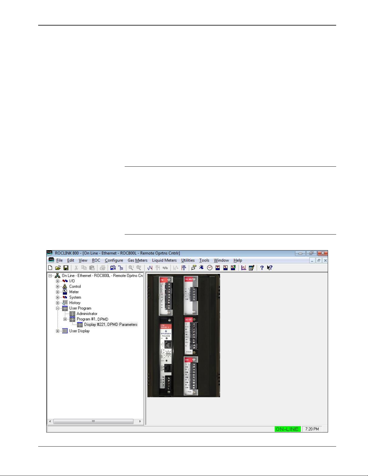
To access the program:
1. From the Directory Tree, select User Program > Program #1,
DPMD.
2. Double-click Display #221, DPMD Parameters.
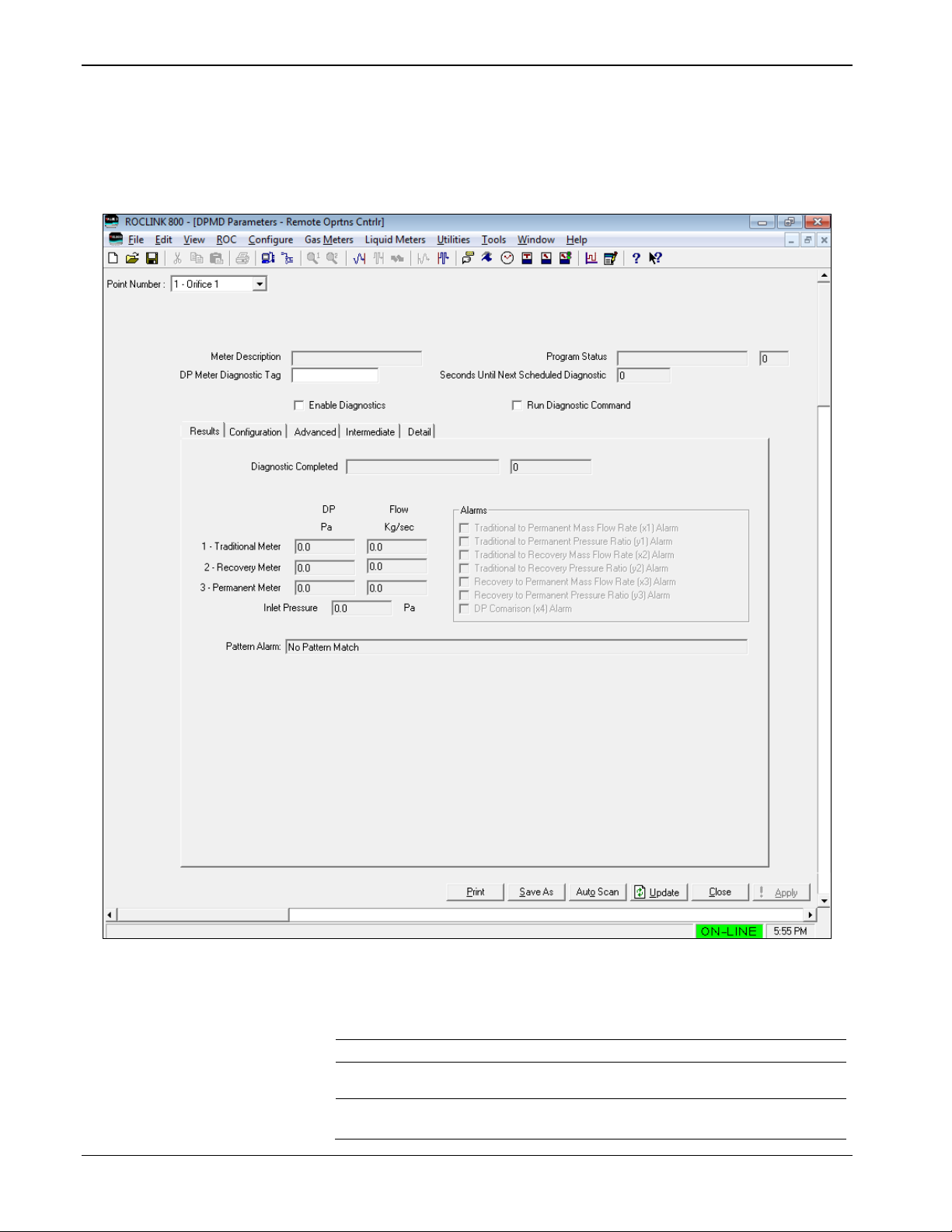
Figure 3-2. DPMD Parameters
1. Review the following fields:
Field
Description
Point Number
Sets the meter for diagnostic.
Meter Description
This read-only field displays the meter
description.
DP Meter
Diagnostic Tag
Sets the description of the meter.
Page 21

DP – Prognosis FC User Manual (for ROC800-Series)
Issued January-2017 Configuration 17
Field
Description
Program Status
This read-only field displays the program
status. For possible status codes and
messages, see Section 4.2 of this manual.
Seconds Until Next
Scheduled
Diagnostic
This read-only field displays the next
scheduled diagnostic in seconds.
Enable Diagnostics
Enables diagnostics for the specified meter.
Run Diagnostic
Command
Select this option to perform an instantaneous
diagnostic of the meter.
2. Proceed to the Section 3.1 – Results tab.
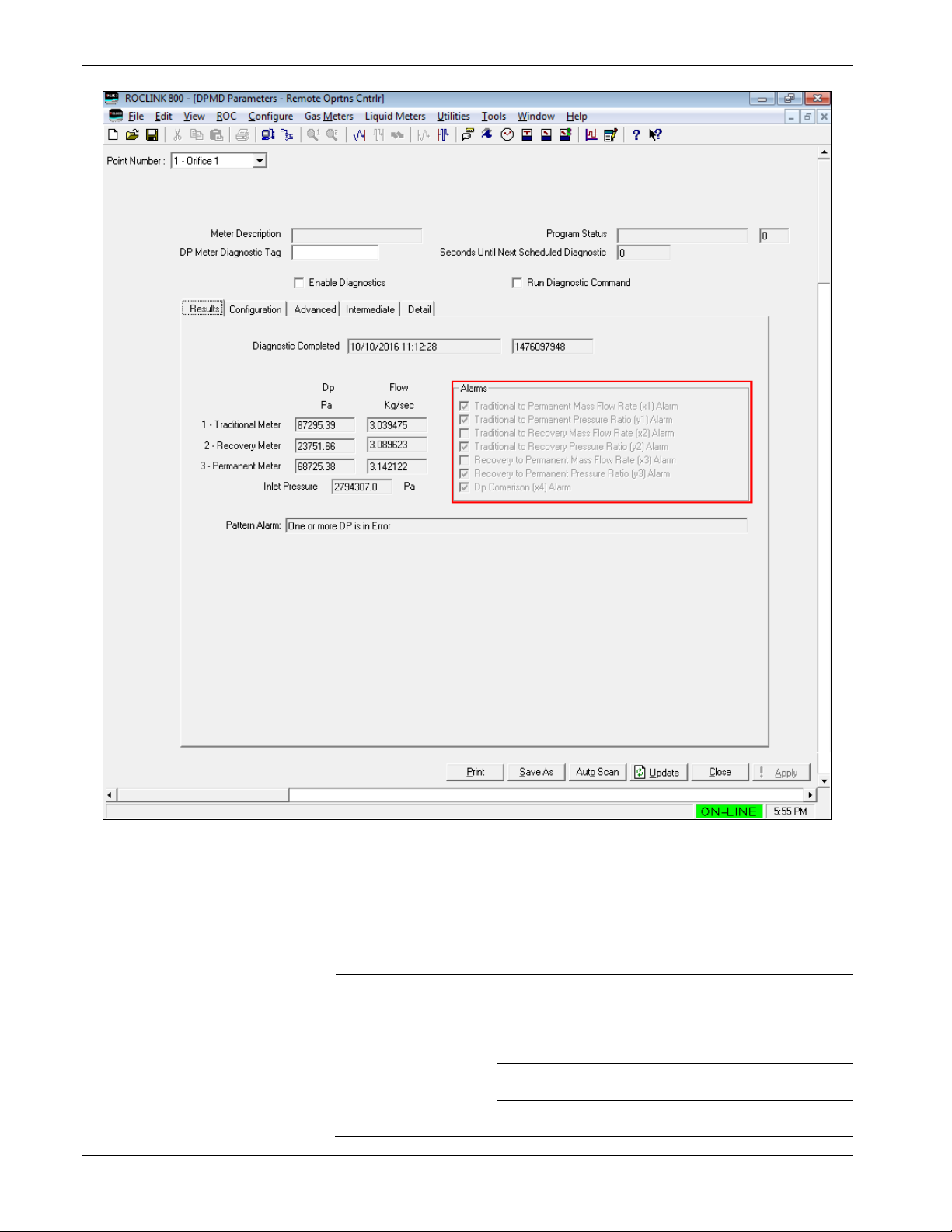
3.1 Results
Each time the Prognosis FC calculations complete, the Results tab of the
Configuration screen provides the summary results of the calculations.
Page 22
DP – Prognosis FC User Manual (for ROC800-Series)
18 Configuration Issued January-2017
Figure 3-3. Results tab
1. Review the following fields:
Field
Description
Diagnostic
Completed
This read-only field displays the timestamp of
the most recent diagnostic run. Provides both
UNIX timestamp and the formatted date/time.
1 – Traditional
Meter
Lists the values for the Traditional Meter.
Note: The Prognosis FC calculations are
performed in metric units – regardless of
the units of measure configured in the
ROC800.
Dp
This read-only field displays the Traditional Dp
used for the calculations.
Flow
This read-only field displays the Mass Flow Rate
as calculated via the Traditional meter.
Page 23

DP – Prognosis FC User Manual (for ROC800-Series)
Issued January-2017 Configuration 19
Field
Description
2 – Recovery Meter
Lists the values for the Recovery Meter.
Note: The Prognosis FC calculations are
performed in metric units – regardless of
the units of measure configured in the
ROC800.
Dp
This read-only field displays the Recovery Dp
used for the calculations.
Flow
This read-only field displays the Mass Flow Rate
as calculated via the recovery meter.
3 – Permanent
Meter
Lists the values for the Permanent Meter.
Note: The Prognosis FC calculations are
performed in metric units – regardless of
the units of measure configured in the
ROC800.
Dp
This read-only field displays the Permanent
Dp used for the calculations.
Flow
This read-only field displays the Mass Flow
Rate as calculated via the Permanent meter.
Inlet Pressure
This read-only field displays the inlet pressure
for the meter(s).
Note: The Prognosis FC calculations are
performed in metric units – regardless of
the units of measure configured in the
ROC800.
Alarms
Checkboxes indicate which – if any – of the
seven diagnostic parameters exceeds
configured acceptable values. When one or
more parameters exceeds acceptable values,
the red box is displayed around this section of
the screen.
Traditional to
Permanent Mass
Flow Rate (x1)
Alarm
When this alarm is selected, there is excessive
difference between the mass flow rates derived
from the traditional and the permanent meters.
Traditional to
Permanent
Pressure Ratio (y1)
Alarm
When this alarm is selected, there is excessive
difference between the observed and
theoretical values for permanent pressure ratio.
Traditional to
Recovery Mass
Flow Rate (x2)
Alarm
When this alarm is selected, there is excessive
difference between the mass flow rates derived
from the traditional and the recovery meters.
Traditional to
Recovery Pressure
Ratio (y2) Alarm
When this alarm is selected, there is excessive
difference between the observed and
theoretical values for recovery to traditional
pressure ratio.
Recovery to
Permanent Mass
Flow Rate (x3)
Alarm
When this alarm is selected, there is excessive
difference between the mass flow rates derived
from the recovery and the permanent meters.
Recovery to
Permanent
Pressure Ratio (y3)
Alarm
When this alarm is selected, there is excessive
difference between the observed and
theoretical values for recovery to permanent
pressure ratio.
Page 24
DP – Prognosis FC User Manual (for ROC800-Series)
20 Configuration Issued January-2017
Field
Description
Dp Comparison (x4)
Alarm
When this alarm is selected, there is excessive
difference between the observed traditional Dp
value and the sum of the recovery and
permanent pressure values
Pattern Alarm
This read-only field displays a text message
describing the results of the pattern matching
algorithm.
2. Proceed to the Section 3.2 – Configuration.
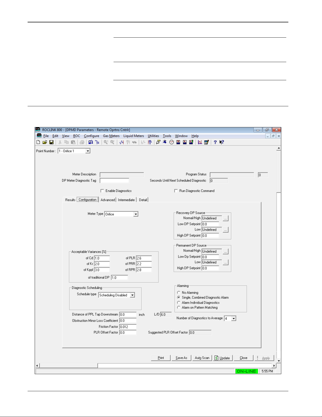
3.2 Configuration
The Configuration tab provides most of the parameters needed to
configure Prognosis FC.
Figure 3-4. Configuration tab
Page 25

DP – Prognosis FC User Manual (for ROC800-Series)
Issued January-2017 Configuration 21
1. Review the values in the following fields:
Field
Description
Meter Type
Selects the appropriate meter type. Click to
select a valid option:
Orifice
Venturi
Cone
Acceptable
Variances [%]
These values serve as the alarm thresholds for
the different diagnostic parameters. You can
increase these values if nuisance alarms are
occurring.
of Cd
Sets the acceptable variance (in percent) of the
discharge coefficient for the traditional meter.
of Kr
Sets the acceptable variance (in percent) of the
flow coefficient for the recovery meter.
of Kppl
Sets the acceptable variance (in percent) of the
flow coefficient for the permanent meter.
of PLR
Sets the acceptable variance (in percent) of the
ratio of permanent to traditional pressure loss.
of PRR
Sets the acceptable variance (in percent) of the
ratio of recovery to traditional pressure loss.
of RPR
Sets the acceptable variance (in percent) of the
ratio of recovery to permanent pressure loss.
of traditional Dp
Sets the acceptable variance (in percent) of the
traditional DP.
Diagnostic
Scheduling
This frame sets the diagnostic calculations for
the meter are to be scheduled. If scheduled,
select the Schedule Type. Click to select a
valid option:
Scheduling Disabled
Scheduling in Days
Scheduling in Hours
Scheduling in Minutes
Scheduling in Seconds
Schedule Type
Sets the time interval between scheduled runs of
Prognosis FC calculations for the meter. The
units of time for the interval are specified with the
Diagnostic Scheduling parameter.
Distance to PPL
Tap Downstream
Sets the distance from the restriction to the far
downstream tap.
If this number is less than the 6 diameters, it will
be ignored. If the value is greater than 6
diameters, a correction value will be applied to
the permanent pressure loss reading to
compensate for excessive distance downstream.
L/D
This read-only field displays the ratio of the far
downstream tap distance to the diameter of the
meter. Ideally, this value should be 6.0.
Page 26

DP – Prognosis FC User Manual (for ROC800-Series)
22 Configuration Issued January-2017
Field
Description
Obstruction Minor
Loss Coefficient
This coefficient is used to compensate for
pressure losses caused by obstructions in the
meter tube located between the downstream tap
and the far downstream tap. One example of
such an obstruction would be a thermowell.
Note: If a thermowell or other obstruction exists
in the flow stream between the
downstream tap and the far downstream
tap.
Friction Factor
Sets the friction factor used to calculate
additional pressure loss if far downstream tap is
located more than 6 diameters downstream.
PLR Offset Factor
Can be used to “zero” the error produced by
anomalies, such as wet gas, non-standard tap
location, and other pressure losses within the
meter
Suggested PLR
Offset Factor
This read-only field displays the PLR offset
factor calculated by the program which can be
used to “zero” the Diagnostics for the meter
Recovery DP
Source
Specifies where the value of the Recovery DP
should be read and the conditions (if applicable)
which will control switching between stacked DP
sensors.
Normal/High
Click to designate input variable from which
the DP should be read for non-stacked DP
installations. For stacked DP installations, this
location designates the parameter for the high
DP instrument value.
Low DP Setpoint
Sets the value which provides the threshold for
switching from the high DP instrument to the low
DP instrument. This is for stacked DP
installations.
Low
Click to designate input variable from which
the Low DP should be read for stacked DP
installations.
High DP Setpoint
Sets the value which provides the threshold for
switching from the low DP instrument to the high
DP instrument. This is for stacked DP
installations.
Permanent DP
Source
Specify where the value of the Permanent DP
should be read and the conditions (if applicable)
which will control switching between stacked DP
sensors.
Normal/High
Click to designate input variable from which
the DP should be read for non-stacked DP
installations. For stacked DP installations, this
location designates the parameter for the high
DP instrument value.
Low DP Setpoint
Sets the value which provides the threshold for
switching from the high DP instrument to the low
DP instrument. This is for stacked DP
installations.
Page 27

DP – Prognosis FC User Manual (for ROC800-Series)
Issued January-2017 Configuration 23
Field
Description
Low
Click to designate input variable from which
the Low DP should be read for stacked DP
installations.
High DP Setpoint
Sets the value which provides the threshold for
switching from the low DP instrument to the high
DP instrument. This is for stacked DP
installations.
Alarming
Specifies the type of alarms to be entered into
the ROC800 Alarm log:
No Alarming
No alarms will be
entered into the
ROC800 alarm log.
Single,Combined
Diagnostic Alarm
If any of the seven
diagnostics are outside
of acceptable ranges,
an alarm is set. The
alarm is not cleared
until all of the
diagnostics are within
range.
Alarm Individual
Diagnostics
Alarms are set and
cleared individually for
each of the seven
diagnostics.
Warning: This mode
can create numerous
alarms.
Alarm on Pattern
Match
If the pattern match
feature reveals a nonconforming pattern, an
alarm is set for that
pattern. The alarm is
cleared either when
the pattern returns a
conforming pattern or
when a different nonconforming pattern is
matched.
Number of
Diagnostics to
Average
When Prognosis FC calculations are executed,
the program can perform multiple consecutive
calculations rapidly and average the results.
Click to specify the number of calculation
repetitions to perform and average at each
scheduled interval.
Note: Improper configuration of this parameter
might result in unexpected or unwanted
behavior. For example, setting the
scheduling type to seconds and setting
the schedule to 5 but setting the number
of diagnostics to average to 7 will result
in continuous execution of the Prognosis
FC at 1-second intervals. In some
applications, this may place an undesirable
load on the ROC800’s main processor.
Page 28

DP – Prognosis FC User Manual (for ROC800-Series)
24 Configuration Issued January-2017
2. Enable the Run Diagnostic Command check box and click Apply
to save the changes.
3. Observe the Program Status Description and Code for indications
of either success of operation or configuration problems.
4. Make corrections as necessary.
5. Proceed to Section 3.3 – Advanced.
3.3 Advanced
Once you have successfully configured the DP Meter Diagnostics
program for a meter run, you can make adjustments to the Advanced
configuration parameters if so you desired.
Figure 3-5. Advanced tab
Page 29

DP – Prognosis FC User Manual (for ROC800-Series)
Issued January-2017 Configuration 25
1. Review the following fields:
Field
Description
Cd Calculation
Method
The coefficient of discharge for the traditional
flow rate calculation can be calculated either
from ISO 5167 or from a curve fit. If the meter
has been calibrated to derive a more precise
definition of discharge coefficient vs Reynolds
number, a curve fit of that calibration data can
be entered here.
Kr Calculation
Method
The flow coefficient for the recovery flow rate
calculation can be calculated either from ISO
5167 or from a curve fit. If the meter has been
calibrated to derive a more precise definition of
flow coefficient vs Reynolds number, a
polynomial curve fit of that calibration data can
be entered here.
Kppl Calculation
Method
The flow coefficient for the permanent pressure
loss rate calculation can be calculated either
from ISO 5167 or from a curve fit. If the meter
has been calibrated to derive a more precise
definition of flow coefficient vs Reynolds
number, a curve fit of that calibration data can
be entered here.
Expected/Calibrated
PLR Calculation
The ratio of traditional DP to permanent
pressure loss DP can be calculated either from
a published equation or from a curve fit. If the
meter has been calibrated to derive a more
precise definition of pressure loss ratio vs
Reynolds number, a curve fit of that calibration
data can be entered here.
Expected/Calibrated
PRR Calculation
The ratio of recovery DP to permanent
pressure loss DP can be calculated either from
a published equation or from a curve fit. If the
meter has been calibrated to derive a more
precise definition of pressure loss ratio vs
Reynolds number, a curve fit of that calibration
data can be entered here.
Expected/Calibrated
RPR Calculation
The ratio of traditional DP to recovery pressure
loss DP can be calculated either from a
published equation or from a curve fit. If the
meter has been calibrated to derive a more
precise definition of pressure loss ratio vs
Reynolds number, a curve fit of that calibration
data can be entered here.
Diagnostic
Calculations Cutoff
Thresholds
Specifies the low DP limits for the diagnostic
calculations:
Low Traditional
DP cutoff
Sets the threshold for diagnostic calculations
based on the traditional DP value. When the
traditional DP value falls below this threshold, the
diagnostic calculations will not be executed. This
feature can be used to prevent extraneous
alarms at very low flow rates.
Page 30

DP – Prognosis FC User Manual (for ROC800-Series)
26 Configuration Issued January-2017
Field
Description
Low Recovery DP
cutoff
Sets the threshold for diagnostic calculations
based on the recovery DP value. When the
recovery DP value falls below this threshold, the
diagnostic calculations will not be executed. This
feature can be used to prevent extraneous
alarms at very low flow rates.
Low Permanent
DP cutoff
Sets the threshold for diagnostic calculations
based on the permanent DP value. When the
permanent DP value falls below this threshold,
the diagnostic calculations will not be executed.
This feature can be used to prevent extraneous
alarms at very low flow rates.
2. Click Apply to save the changes.
3. Proceed to Section 3.4 – Intermediate.
3.4 Intermediate
The Intermediate tab provides information about intermediate values
calculated during the Prognosis FC calculations.
Note: The Prognosis FC calculations are performed in metric units –
regardless of the units of measure configured in the ROC800.
Page 31

DP – Prognosis FC User Manual (for ROC800-Series)
Issued January-2017 Configuration 27
Figure 3-6. Intermediate tab
Page 32

DP – Prognosis FC User Manual (for ROC800-Series)
28 Configuration Issued January-2017
1. Review the following fields:
Field
Description
Restriction
Diameter (d)
This read-only field displays the temperaturecorrected meter restriction diameter.
Inlet Diameter (D)
This read-only field displays the temperaturecorrected meter inlet diameter.
Beta
This read-only field displays the calculated
Beta ratio
Meter Inlet Area
This read-only field displays the cross-sectional
area of the meter inlet.
Meter Throat Area
This read-only field displays the cross-sectional
area of the meter restriction.
Velocity of
Approach factor
(E)
This read-only field displays the dimensionless
velocity of approach factor for the meter.
Isentropic
Exponent (kappa)
This read-only field displays the dimensionless
isentropic exponent for the flowing fluid.
Inlet Density (rho)
This read-only field displays the density of the
flowing fluid at the meter inlet.
Viscosity (mu)
This read-only field displays the dynamic
viscosity of the flowing fluid.
Tradinl Expansion
Factor (epsilon)
This read-only field displays the expansion
factor of the traditional meter.
Extra L/D
This read-only field displays the additional
dimensionless pipe diameters between the ideal
and actual location of the far downstream tap.
Kloss
This read-only field displays the total amount of
equivalent dimensionless pipe diameters
(including Extra L/D and any obstructions) for
correcting the far downstream pressure reading.
Head loss (hl)
This read-only field displays the amount by
which the far downstream Dp reading will be
corrected to account for additional losses.
Upstream Static
Pressure
This read-only field displays the upstream static
pressure.
Traditional Dp
Read
This read-only field displays the traditional Dp
value read from the configured input.
Recovery Dp Read
This read-only field displays the recovery Dp
value read from the configured input.
Permanent Dp
Read
This read-only field displays the permanent Dp
value read from the configured input.
Reynolds Number
(Re)
This read-only field displays the calculated
Reynold number.
Discharge
Coefficient (Cd)
This read-only field displays the coefficient of
discharge for the traditional meter.
Inferred Traditional
Dp
This read-only field displays the sum of the
Recovery DP Read and the Permanent Dp
Read.
Traditional DP
Error %
This read-only field displays the difference [%]
between the Traditional Dp Read and the
Inferred Traditional Dp.
Recovery
This read-only field displays the recovery meter
coefficient and corrections made to it.
Meter Coefficient
Kr, Kppl
This read-only field displays the meter
coefficient Kr calculated (vs Reynolds number)
using the method selected on the Advanced
tab.
Page 33

DP – Prognosis FC User Manual (for ROC800-Series)
Issued January-2017 Configuration 29
Field
Description
Meter Coefficient
Kr’, Kppl’
This read-only field displays the meter
coefficient Kr corrected for Head Loss (hl).
Meter Coefficient
Kr’Z, Kppl’Z
This read-only field displays the meter
coefficient Kr corrected for Head Loss (hl) and
PLR Offset Factor defined on the
Configuration tab.
Permanent
This read-only field displays the permanent
meter coefficient and corrections made to it
Meter Coefficient
Kr, Kppl
This read-only field displays the meter
coefficient Kppl calculated (vs Reynolds
number) using the method selected on the
Advanced tab.
Meter Coefficient
Kr’, Kppl’
This read-only field displays the meter
coefficient Kppl corrected for Head Loss (hl).
Meter Coefficient
Kr’Z, Kppl’Z
This read-only field displays the meter
coefficient Kppl corrected for Head Loss (hl)
and PLR Offset Factor defined on the
Configuration tab.
Traditional Mass
Flow Rate
This read-only field displays the mass flow rate
as calculated from the traditional meter.
Recovery Mass
Flow Rate
This read-only field displays the mass flow rate
as calculated from the recovery meter.
Permanent Mass
Flow Rate
This read-only field displays the mass flow rate
[Kg/sec] as calculated from the permanent
meter.
Trad/PPL Rate
Actual Error (psi)
This read-only field displays the actual error
between the traditional and permanent meter
flow rates.
Trad/Rec Rate
Actual Error
(lambda)
This read-only field displays the actual error
between the traditional and recovery meter flow
rates.
Rec/PPL Rate
Actual Error (chi)
This read-only field displays the actual error [%]
between the recovery and permanent meter
flow rates.
Trad/PPL Rate
Aceptable Error
(phi)
This read-only field displays the acceptable
error between the traditional and permanent
meter flow rates.
Trad/Rec Rate
Aceptable Error
(nu)
This read-only field displays the acceptable
error between the traditional and recovery meter
flow rates.
Rec/PPL Rate
Acceptable Error
(xi)
This read-only field displays the acceptable
error [%] between the recovery and permanent
meter flow rates.
PLR
This read-only field displays the uncorrected
and corrected pressure loss ratio information for
the traditional to permanent pressure loss ratio.
Actual
This read-only field displays the actual
pressure ratio.
Calibration
This read-only field displays the theoretical
(uncorrected) pressure ratio.
Calib’
This read-only field displays the theoretical
pressure loss ratio corrected for meter
coefficient Kr corrected for Head Loss (hl).
Calib’Z
This read-only field displays the theoretical
pressure loss ratio corrected for Head Loss (hl)
and PLR Offset Factor.
Page 34

DP – Prognosis FC User Manual (for ROC800-Series)
30 Configuration Issued January-2017
Field
Description
PRR
This read-only field displays the uncorrected
and corrected pressure loss ratio information for
the traditional to recovery pressure loss ratio.
Actual
This read-only field displays the actual
pressure ratio.
Calibration
This read-only field displays the theoretical
(uncorrected) pressure ratio.
Calib’
Displays the theoretical pressure loss ratio
corrected for meter coefficient Kr corrected for
Head Loss (hl).
Calib’Z
Displays the theoretical pressure loss ratio
corrected for Head Loss (hl) and PLR Offset
Factor.
RPR
This read-only field displays the uncorrected
and corrected pressure loss ratio information for
the recovery to permanent pressure loss ratio.
Actual
This read-only field displays the actual
pressure ratio.
Calib’Z
This read-only field displays the theoretical
pressure loss ratio corrected for Head Loss (hl)
and PLR Offset Factor. This will be identical to
the Actual value for RPR
PLR Error
Difference
This read-only field displays the calculated
difference between the actual and the corrected
theoretical PLR
PRR Error
Difference
This read-only field displays the calculated
difference between the actual and the corrected
theoretical PRR.
RPR Error
Difference
This read-only field displays the calculated
difference between the actual and the corrected
theoretical RPR.
2. Proceed to Section 3.5 – Detail.
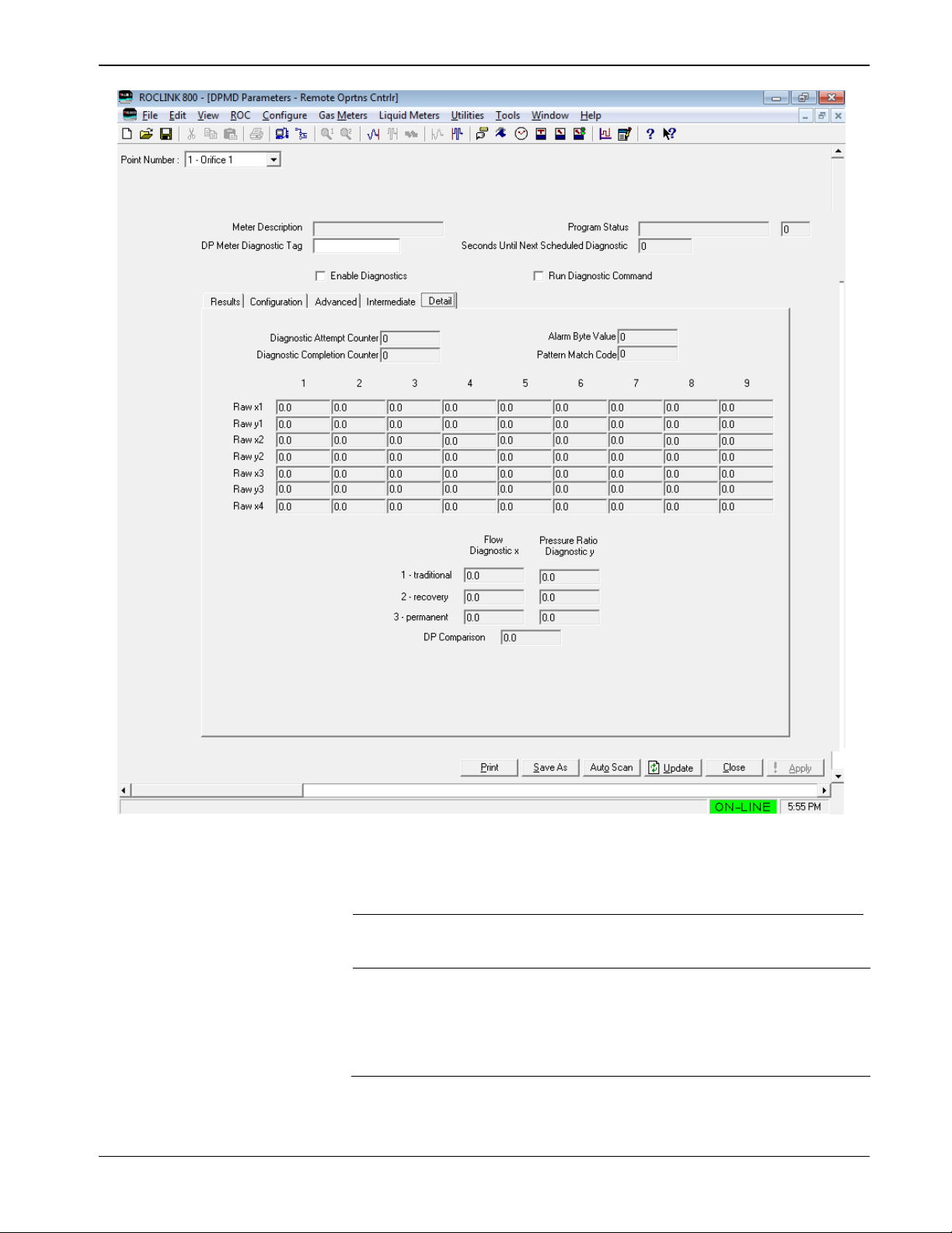
3.5 Detail
The Detail tab provides more detailed information that the summary tab.
It also contains a limited amount of diagnostic information:
Page 35
DP – Prognosis FC User Manual (for ROC800-Series)
Issued January-2017 Configuration 31
Figure 3-7. Detail tab
1. Review the following fields:
Field
Description
Diagnostic Attempt
Counter
This read-only field displays each time a
diagnostic run begins; this counter is
increased.
Diagnostic
Completion
Counter
This read-only field displays each time a
diagnostic run reaches successful completion,
this counter is incremented. If the Diagnostic
Attempt Counter is increasing faster than the
Diagnostic Completion Counter, an error
condition is indicated.
Page 36

DP – Prognosis FC User Manual (for ROC800-Series)
32 Configuration Issued January-2017
Field
Description
Alarm Byte Value
This read-only field displays the numeric
representation of currently-active alarms is
displayed in this field. This is a bit-mapped 8-bit
integer:
Bit 0 – Traditional to Permanent Mass Flow
Rate Alarm
Bit 1 – Traditional to Permanent Pressure
Ratio Alarm
Bit 2 – Traditional to Recovery Mass Flow
Rate Alarm
Bit 3 – Traditional to Recovery Pressure Ratio
Alarm
Bit 4 – Recovery to Permanent Mass Flow
Rate Alarm
Bit 5 – Recovery to Permanent Pressure Ratio
Alarm
Bit 6 – Dp Comparison Alarm
Bit 7 – Not used
Note: This field is a numeric representation of
the Alarms section displayed on the
Results tab
Pattern Match
Code
This read-only field displays the numeric version
of the results of pattern matching. See Chapter 4
– Reference of this document for a listing of the
coded values.
Raw x1, y1, x2, y2,
x3, y3, x4
This read-only field displays the individual
diagnostic values from each repetition. All of the
unused repetition columns are filled with zeros
The Prognosis FC functions can be configured to
run from 1 to 9 repetitions of calculations for
each commanded execution. The results of this
set of runs is averaged.
1 – traditional
This read-only field displays the averaged
values of the individual parameters.
Flow Diagnostic
x
This read-only field displays the flow diagnostic
(x1) for the traditional meter.
Pressure Ratio
Diagnostic y
This read-only field displays the pressure ratio
diagnostic (y1) for the traditional meter.
2 – recovery
This read-only field displays the averaged
values of the individual parameters.
Flow Diagnostic
x
This read-only field displays the flow diagnostic
(x2) for the recovery meter.
Pressure Ratio
Diagnostic y
This read-only field displays the pressure ratio
diagnostic (y2) for the recovery meter.
3 - permanent
This read-only field displays the averaged
values of the individual parameters.
Flow Diagnostic
x
This read-only field displays the flow diagnostic
(x3) for the permanent meter.
Pressure Ratio
Diagnostic y
This read-only field displays the pressure ratio
diagnostic (y3) for the permanent meter.
Dp Comparison
This read-only field displays the averaged value
of the DpL-comparison diagnostic.
2. Proceed to Section 3.6 – Saving the Configuration.
Page 37
DP – Prognosis FC User Manual (for ROC800-Series)
Issued January-2017 Configuration 33
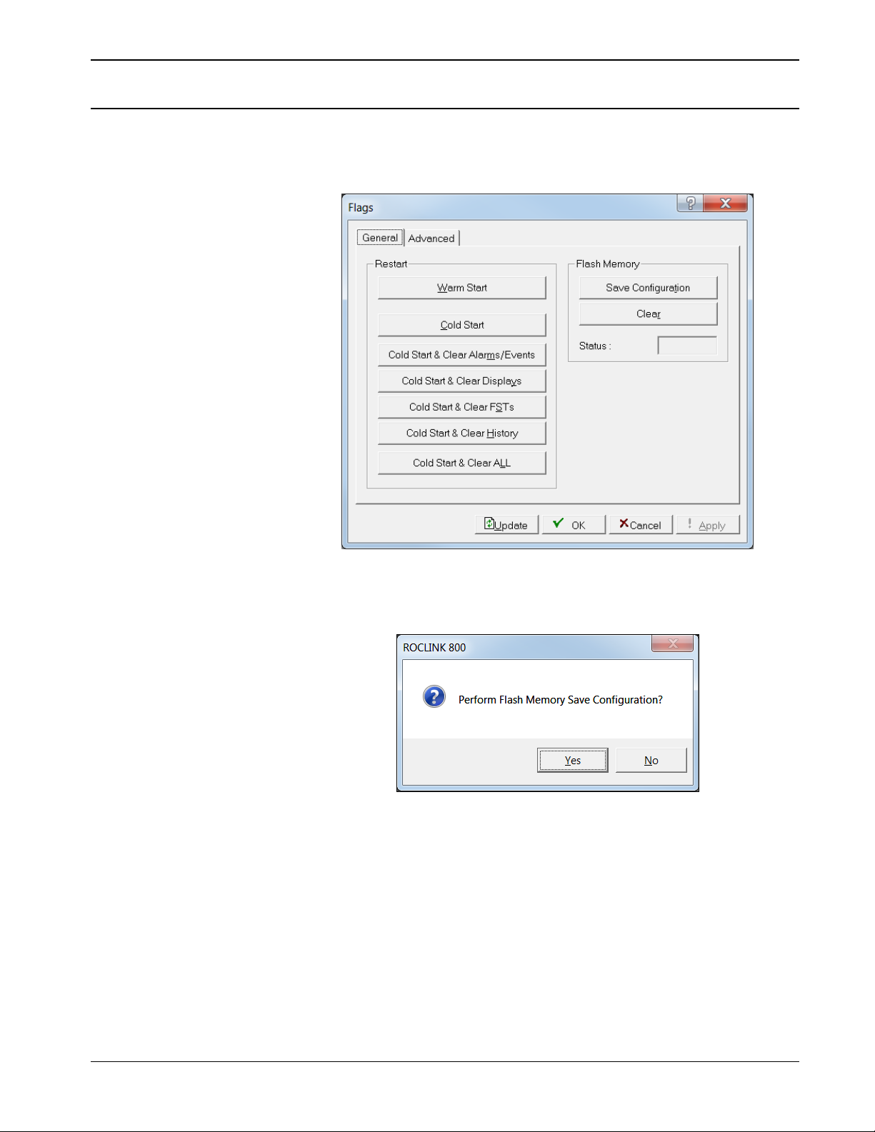
3.6 Saving the Configuration
Whenever you modify or change the configuration, it is a good practice
to save the final configuration to memory. To save the configuration:
Select ROC > Flags. The Flags screen displays:
Figure 3-8. Flags
1. Click Save Configuration. A verification message displays:
Figure 3-9. Save Verification
Page 38
DP – Prognosis FC User Manual (for ROC800-Series)
34 Configuration Issued January-2017
2. Click Yes. When the save process completes, a confirmation
message displays:
Figure 3-10. Confirmation
Note: Depending on the size and complexity of the user program,
this process may take several minutes. When the process
ends, the Status field on the Flags screen displays
Completed.
Figure 3-11. Flags, Status - Completed
3. Click Update on the Flags screen. This completes the process of
saving your new configuration.
Note: For archive purposes, you should also save this configuration
to your PC’s hard drive or a removable media (such as a
flash drive) using the File > Save Configuration option on
the ROCLINK 800 menu bar.
Page 39

DP – Prognosis FC User Manual (for ROC800-Series)
Issued January-2017 Reference 35
Chapter 4 – Reference
This section provides information on the user-defined point types the
DP Meter Diagnostics program uses:
Point Type 220: DP Meter Diagnostics Parameters
The following topics are discussed in this section:
Program Status Codes and Messages
Pattern Match Codes and Messages
Zeroing the meter for Prognosis FC
Page 40

DP – Prognosis FC User Manual (for ROC800-Series)
36 Reference Issued January-2017
4.1 Point Type 220: DP – Prognosis FC Parameters
Point type 220 contains the parameters for the configuration and the output parameters of the DP – Prognosis FC user program. The program
supports up to 12 logicals of point type 220.
Point Type 220: DPMD Configuration Parameters
Parm
#
Name
Access
System
or User
Update
Data
Type
Length
Range
Default
Version
Description of functionality
and meaning of values
0
Tag
R/W
User
AC
10
0x20 0x7E for
each ASCII
character
“”
1.00
An alternate text descriptor
1
Cd Polynomial A
R/W
User
FL
4
Any IEEE floating
point value
0.0
1.00
Coefficient used for calculating
Cd of Cd Method is anything
other than “ISO 5167 equation”
2
Cd Polynomial B
R/W
User
FL
4
Any IEEE floating
point value
0.0
1.00
Coefficient used for calculating
Cd of Cd Method is anything
other than “ISO 5167 equation”
3
Cd Polynomial C
R/W
User
FL
4
Any IEEE floating
point value
0.0
1.00
Coefficient used for calculating
Cd of Cd Method is anything
other than “ISO 5167 equation”
4
Cd Polynomial D
R/W
User
FL
4
Any IEEE floating
point value
0.0
1.00
Coefficient used for calculating
Cd of Cd Method is anything
other than “ISO 5167 equation”
5
Kr Polynomial A
R/W
User
FL
4
Any IEEE floating
point value
0.0
1.00
If Kr Method = “derive Kr from
curve-fit polynomial” then Kr is
calculated using a Cd computed
= KrA+(KrB*Re)+(KrC*( Re
^2))+(KrD*( Re ^3))
6
Kr Polynomial B
R/W
User
FL
4
Any IEEE floating
point value
0.0
1.00
If Kr Method = “derive Kr from
curve-fit polynomial” then Kr is
calculated using a Cd computed
= KrA+(KrB*Re)+(KrC*( Re
^2))+(KrD*( Re ^3))
7
Kr Polynomial C
R/W
User
FL
4
Any IEEE floating
point value
0.0
1.00
If Kr Method = “derive Kr from
curve-fit polynomial” then Kr is
calculated using a Cd computed
= KrA+(KrB*Re)+(KrC*( Re
^2))+(KrD*( Re ^3))
8
Kr Polynomial D
R/W
User
FL
4
Any IEEE floating
point value
0.0
1.00
If Kr Method = “derive Kr from
curve-fit polynomial” then Kr is
calculated using a Cd computed
= KrA+(KrB*Re)+(KrC*( Re
^2))+(KrD*( Re ^3))
Page 41

DP – Prognosis FC User Manual (for ROC800-Series)
Issued January-2017 Reference 37
Point Type 220: DPMD Configuration Parameters
Parm
#
Name
Access
System
or User
Update
Data
Type
Length
Range
Default
Version
Description of functionality
and meaning of values
9
Kppl Polynomial A
R/W
User
FL
4
Any IEEE floating
point value
0.0
1.00
If Kppl Method = “derive Kppl
from curve-fit polynomial” then
Kppl is calculated using a Cd
computed =
KpplA+(KpplB*Re)+(KpplC*( Re
^2))+(KpplD*( Re ^3))
10
Kppl Polynomial B
R/W
User
FL
4
Any IEEE floating
point value
0.0
1.00
If Kppl Method = “derive Kppl
from curve-fit polynomial” then
Kppl is calculated using a Cd
computed =
KpplA+(KpplB*Re)+(KpplC*( Re
^2))+(KpplD*( Re ^3))
11
Kppl Polynomial C
R/W
User
FL
4
Any IEEE floating
point value
0.0
1.00
If Kppl Method = “derive Kppl
from curve-fit polynomial” then
Kppl is calculated using a Cd
computed =
KpplA+(KpplB*Re)+(KpplC*( Re
^2))+(KpplD*( Re ^3))
12
Kppl Polynomial D
R/W
User
FL
4
Any IEEE floating
point value
0.0
1.00
If Kppl Method = “derive Kppl
from curve-fit polynomial” then
Kppl is calculated using a Cd
computed =
KpplA+(KpplB*Re)+(KpplC*( Re
^2))+(KpplD*( Re ^3))
13
PLR Polynomial A
R/W
User
FL
4
Any IEEE floating
point value
0.0
1.00
Coefficient used for calculating
PLR if PLR Method is anything
other than “ISO 5167 equation”
14
PLR Polynomial B
R/W
User
FL
4
Any IEEE floating
point value
0.0
1.00
Coefficient used for calculating
PLR if PLR Method is anything
other than “ISO 5167 equation”
15
PLR Polynomial C
R/W
User
FL
4
Any IEEE floating
point value
0.0
1.00
Coefficient used for calculating
PLR if PLR Method is anything
other than “ISO 5167 equation”
16
PLR Polynomial D
R/W
User
FL
4
Any IEEE floating
point value
0.0
1.00
Coefficient used for calculating
PLR if PLR Method is anything
other than “ISO 5167 equation”
17
PRR Polynomial A
R/W
User
FL
4
Any IEEE floating
point value
0.0
1.00
Coefficient used for calculating
PRR if PRR Method is anything
other than “calculate from PLR
and theoretical relationships”
Page 42

DP – Prognosis FC User Manual (for ROC800-Series)
38 Reference Issued January-2017
Point Type 220: DPMD Configuration Parameters
Parm
#
Name
Access
System
or User
Update
Data
Type
Length
Range
Default
Version
Description of functionality
and meaning of values
18
PRR Polynomial B
R/W
User
FL
4
Any IEEE floating
point value
0.0
1.00
Coefficient used for calculating
PRR if PRR Method is anything
other than “calculate from PLR
and theoretical relationships”
19
PRR Polynomial C
R/W
User
FL
4
Any IEEE floating
point value
0.0
1.00
Coefficient used for calculating
PRR if PRR Method is anything
other than “calculate from PLR
and theoretical relationships”
20
PRR Polynomial D
R/W
User
FL
4
Any IEEE floating
point value
0.0
1.00
Coefficient used for calculating
PRR if PRR Method is anything
other than “calculate from PLR
and theoretical relationships”
21
RPR Polynomial A
R/W
User
FL
4
Any IEEE floating
point value
0.0
1.00
Coefficient used for calculating
RPR if RPR Method is anything
other than “calculate from PLR
and theoretical relationships”
22
RPR Polynomial B
R/W
User
FL
4
Any IEEE floating
point value
0.0
1.00
Coefficient used for calculating
RPR if RPR Method is anything
other than “calculate from PLR
and theoretical relationships”
23
RPR Polynomial C
R/W
User
FL
4
Any IEEE floating
point value
0.0
1.00
Coefficient used for calculating
RPR if RPR Method is anything
other than “calculate from PLR
and theoretical relationships”
24
RPR Polynomial D
R/W
User
FL
4
Any IEEE floating
point value
0.0
1.00
Coefficient used for calculating
RPR if RPR Method is anything
other than “calculate from PLR
and theoretical relationships”
25
PPL Tap Distance
R/W
User
FL
4
Any positive, non-
zero IEEE floating
point value
0.0
1.00
Distance between the restriction
(orifice plate) and the PPL
pressure tap. Units of measure
are same as used for orifice and
pipe diameter.
26
Obstruction Minor Loss Coefficient
R/W
User
FL
4
Any positive, non-
zero IEEE floating
point value
0.0
1.00
Sum of minor loss coefficients
for any obstructions between
the flow restriction (orifice plate)
and the PPL pressure tap
27
Friction Factor
R/W
User
FL
4
Any positive, non-
zero IEEE floating
point value
0.012
1.00
Friction factor for calculating
pressure loss in the meter body
Page 43

DP – Prognosis FC User Manual (for ROC800-Series)
Issued January-2017 Reference 39
Point Type 220: DPMD Configuration Parameters
Parm
#
Name
Access
System
or User
Update
Data
Type
Length
Range
Default
Version
Description of functionality
and meaning of values
28
PLR Offset Factor
R/W
User
FL
4
Any positive, non-
zero IEEE floating
point value
0.0
1.00
Factor for offsetting the PLR of
the meter
29
Acceptable Variance of Cd
R/W
User
FL
4
Any positive, non-
zero IEEE floating
point value
1.0
1.00
Maximum acceptable variance
percentage of discharge
coefficient
30
Acceptable Variance of Kr
R/W
User
FL
4
Any positive, non-
zero IEEE floating
point value
2.0
1.00
Maximum acceptable variance
percentage of recovery meter
coefficient
31
Acceptable Variance of Kppl
R/W
User
FL
4
Any positive, non-
zero IEEE floating
point value
3.0
1.00
Maximum acceptable variance
percentage of permanent
pressure loss meter coefficient
32
Acceptable Variance of PLR
R/W
User
FL
4
Any positive, non-
zero IEEE floating
point value
2.6
1.00
Maximum acceptable variance
permanent pressure loss ratio
33
Acceptable Variance of PRR
R/W
User
FL
4
Any positive, non-
zero IEEE floating
point value
2.2
1.00
Maximum acceptable variance
recovery pressure loss ratio
34
Acceptable Variance of RPR
R/W
User
FL
4
Any positive, non-
zero IEEE floating
point value
2.8
1.00
Maximum acceptable variance
of ratio of pressure recovery
pressure to permanent pressure
loss
35
Acceptable Variance of Traditional
Dp
R/W
User
FL
4
Any positive, non-
zero IEEE floating
point value
1.0
1.00
Maximum acceptable variance
of the measured traditional Dp
from the inferred traditional Dp
36
Cd Text Polynomial A
RW
User
AC
20
Any valid
numerical ASCII
characters
“0.0”
1.00
Text version of the Cd
polynomial coefficient A
37
Cd Text Polynomial B
RW
User
AC
20
Any valid
numerical ASCII
characters
“0.0”
1.00
Text version of the Cd
polynomial coefficient B
38
Cd Text Polynomial C
RW
User
AC
20
Any valid
numerical ASCII
characters
“0.0”
1.00
Text version of the Cd
polynomial coefficient C
39
Cd Text Polynomial D
RW
User
AC
20
Any valid
numerical ASCII
characters
“0.0”
1.00
Text version of the Cd
polynomial coefficient D
40
Kr Text Polynomial A
RW
User
AC
20
Any valid
numerical ASCII
characters
“0.0”
1.00
Text version of the Kr
polynomial coefficient A
Page 44

DP – Prognosis FC User Manual (for ROC800-Series)
40 Reference Issued January-2017
Point Type 220: DPMD Configuration Parameters
Parm
#
Name
Access
System
or User
Update
Data
Type
Length
Range
Default
Version
Description of functionality
and meaning of values
41
Kr Text Polynomial B
RW
User
AC
20
Any valid
numerical ASCII
characters
“0.0”
1.00
Text version of the Kr
polynomial coefficient B
42
Kr Text Polynomial C
RW
User
AC
20
Any valid
numerical ASCII
characters
“0.0”
1.00
Text version of the Kr
polynomial coefficient C
43
Kr Text Polynomial D
RW
User
AC
20
Any valid
numerical ASCII
characters
“0.0”
1.00
Text version of the Kr
polynomial coefficient D
44
Kppl Text Polynomial A
RW
User
AC
20
Any valid
numerical ASCII
characters
“0.0”
1.00
Text version of the Kppl
polynomial coefficient A
45
Kppl Text Polynomial B
RW
User
AC
20
Any valid
numerical ASCII
characters
“0.0”
1.00
Text version of the Kppl
polynomial coefficient B
46
Kppl Text Polynomial C
RW
User
AC
20
Any valid
numerical ASCII
characters
“0.0”
1.00
Text version of the Kppl
polynomial coefficient C
47
Kppl Text Polynomial D
RW
User
AC
20
Any valid
numerical ASCII
characters
“0.0”
1.00
Text version of the Kppl
polynomial coefficient D
48
PLR Text Polynomial A
RW
User
AC
20
Any valid
numerical ASCII
characters
“0.0”
1.00
Text version of the PLR
polynomial coefficient A
49
PLR Text Polynomial B
RW
User
AC
20
Any valid
numerical ASCII
characters
“0.0”
1.00
Text version of the PLR
polynomial coefficient B
50
PLR Text Polynomial C
RW
User
AC
20
Any valid
numerical ASCII
characters
“0.0”
1.00
Text version of the PLR
polynomial coefficient C
51
PLR Text Polynomial D
RW
User
AC
20
Any valid
numerical ASCII
characters
“0.0”
1.00
Text version of the PLR
polynomial coefficient D
52
PRR Text Polynomial A
RW
User
AC
20
Any valid
numerical ASCII
characters
“0.0”
1.00
Text version of the PRR
polynomial coefficient A
53
PRR Text Polynomial B
RW
User
AC
20
Any valid
numerical ASCII
characters
“0.0”
1.00
Text version of the PRR
polynomial coefficient B
Page 45

DP – Prognosis FC User Manual (for ROC800-Series)
Issued January-2017 Reference 41
Point Type 220: DPMD Configuration Parameters
Parm
#
Name
Access
System
or User
Update
Data
Type
Length
Range
Default
Version
Description of functionality
and meaning of values
54
PRR Text Polynomial C
RW
User
AC
20
Any valid
numerical ASCII
characters
“0.0”
1.00
Text version of the PRR
polynomial coefficient C
55
PRR Text Polynomial D
RW
User
AC
20
Any valid
numerical ASCII
characters
“0.0”
1.00
Text version of the PRR
polynomial coefficient D
56
RPR Text Polynomial A
RW
User
AC
20
Any valid
numerical ASCII
characters
“0.0”
1.00
Text version of the RPR
polynomial coefficient A
57
RPR Text Polynomial B
RW
User
AC
20
Any valid
numerical ASCII
characters
“0.0”
1.00
Text version of the RPR
polynomial coefficient B
58
RPR Text Polynomial C
RW
User
AC
20
Any valid
numerical ASCII
characters
“0.0”
1.00
Text version of the RPR
polynomial coefficient C
59
RPR Text Polynomial D
RW
User
AC
20
Any valid
numerical ASCII
characters
“0.0”
1.00
Text version of the RPR
polynomial coefficient D
60
Recovery Low DP Setpoint
R/W
User
FL
4
Any positive, non-
zero IEEE floating
point value
0.0
1.00
If Regular Dp source is being
used and Dp falls below this
setpoint value, the system will
switch to using the Low DP
source.
61
Recovery High Dp Setpoint
R/W
User
FL
4
Any positive, non-
zero IEEE floating
point value
0.0
1.00
If low DP source is being used
and Dp rises above this value,
the system will switch to use the
Regular Dp source
62
Permanent Low DP Setpoint
R/W
User
FL
4
Any positive, non-
zero IEEE floating
point value
0.0
1.00
If Regular Dp source is being
used and Dp falls below this
setpoint value, the system will
switch to using the Low DP
source.
63
Permanent High Dp Setpoint
R/W
User
FL
4
Any positive, non-
zero IEEE floating
point value
0.0
1.00
If low DP source is being used
and Dp rises above this value,
the system will switch to use the
Regular Dp source
64
Recovery Dp Source
R/W
User
TLP 3 Any valid TLP
(assumed to be a
floating point TLP)
0,0,0
1.00
Source of differential pressure
signal measured from
downstream tap to PPL tap.
Page 46

DP – Prognosis FC User Manual (for ROC800-Series)
42 Reference Issued January-2017
Point Type 220: DPMD Configuration Parameters
Parm
#
Name
Access
System
or User
Update
Data
Type
Length
Range
Default
Version
Description of functionality
and meaning of values
65
Recovery Low Dp Source
R/W
User
TLP 3 Any valid TLP
(assumed to be a
floating point TLP)
0,0,0
1.00
Source of differential pressure
signal measured from
downstream tap to PPL tap to
be used for “low” side of a
stacked DP arrangement.
66
Permanent Dp Source
R/W
User
TLP 3 Any valid TLP
(assumed to be a
floating point TLP)
0,0,0
1.00
Source of differential pressure
signal measured from upstream
tap to PPL tap.
67
Permanent Low Dp Source
R/W
User
TLP 3 Any valid TLP
(assumed to be a
floating point TLP)
0,0,0
1.00
Source of differential pressure
signal measured from upstream
tap to PPL tap to be used for
“low” side of a stacked DP
arrangement.
68
Enable DPMD
R/W
User
UINT8 1 0-1
0
1.00
Valid values are:
0 = Disable DPMD for this
meter
1 = Enable DPMD for this meter
69
Meter Type
R/W
User
UINT8 1 0-2
0
1.00
Valid values are:
0 = Orifice
1 = Venturi
2 = Cone
Page 47

DP – Prognosis FC User Manual (for ROC800-Series)
Issued January-2017 Reference 43
Point Type 220: DPMD Configuration Parameters
Parm
#
Name
Access
System
or User
Update
Data
Type
Length
Range
Default
Version
Description of functionality
and meaning of values
70
PLR Method
R/W
User
UINT8 1 0-8
1
1.00
Valid values are:
0 – Use ISO 5167-2 equation 7
for all Beta ratios
1 – Use f(Beta) equation
disclosed by Stevens in
2012 for Beta ratios above
0.55
2 – Direct polynomial curve-fit
PLR = A + B*Re + C*Re^2 +
D*Re^3
3 – Direct curve fit PLR = A +
B*(e^(C*Re))
4 – Direct curve fit PLR = A +
B*(10^(C*Re))
5 – Direct curve fit PLR = A +
B*ln((C*Re))
6 – Direct curve fit PLR = A +
B*log((C*Re))
7 – Direct curve fit PLR = A +
B*(C^(D*Re))
8 – Direct curve fit PLR = A + B
*((C*Re)^D)
Note: Methods 0 and 1 are only
valid for an Orifice Meter.
71
Generate Events
R/W
User
UINT8 1 0-1
1
1.00
Valid values are:
0 – Generate events in the
event log when meter
diagnostic configuration
parameters are modified
1 – Do not generate events
72
Generate Alarms
R/W
User
UINT8 1 0-3
3
1.00
Valid values are:
0 – Do not generate alarms
1 – Generate only a single,
combined alarm for all
diagnostics
2 – Generate alarms based on
the seven individual
diagnostics
3 – Generate alarm based upon
pattern matching
Page 48

DP – Prognosis FC User Manual (for ROC800-Series)
44 Reference Issued January-2017
Point Type 220: DPMD Configuration Parameters
Parm
#
Name
Access
System
or User
Update
Data
Type
Length
Range
Default
Version
Description of functionality
and meaning of values
73
Kr Method
R/W
User
UINT8 1 0-8
0
1.00
Valid values are:
0 – Derive Kr using Cd derived
ISO 5167 equation 4
1 – Derive Kr using Cd from
polynomial curve-fit Cd = A +
B*Re + C*Re^2 + D*Re^3
2 – Direct polynomial curve-fit
Kr = A + B*Re + C*Re^2 +
D*Re^3
3 – Direct curve fit Kr = A +
B*(e^(C*Re))
4 – Direct curve fit Kr = A +
B*(10^(C*Re))
5 – Direct curve fit Kr = A +
B*ln((C*Re))
6 – Direct curve fit Kr = A +
B*log((C*Re))
7 – Direct curve fit Kr = A +
B*(C^(D*Re))
8 – Direct curve fit Kr = A + B
*((C*Re)^D)
Note: Methods 0 and 1 are only
valid for an Orifice Meter.
Page 49

DP – Prognosis FC User Manual (for ROC800-Series)
Issued January-2017 Reference 45
Point Type 220: DPMD Configuration Parameters
Parm
#
Name
Access
System
or User
Update
Data
Type
Length
Range
Default
Version
Description of functionality
and meaning of values
74
Kppl Method
R/W
User
UINT8 1 0-8
0
1.00
Valid values are:
0 – Derive Kppl using Cd
derived ISO 5167 equation 4
1 – Derive Kppl using Cd from
polynomial curve-fit Cd = A +
B*Re + C*Re^2 + D*Re^3
2 – Direct polynomial curve-fit
Kppl = A + B*Re + C*Re^2 +
D*Re^3
3 – Direct curve fit Kppl = A +
B*(e^(C*Re))
4 – Direct curve fit Kppl = A +
B*(10^(C*Re))
5 – Direct curve fit Kppl = A +
B*ln((C*Re))
6 – Direct curve fit Kppl = A +
B*log((C*Re))
7 – Direct curve fit Kppl = A +
B*(C^(D*Re))
8 – Direct curve fit Kppl = A + B
*((C*Re)^D)
Note: Methods 0 and 1 are only
valid for an Orifice Meter.
75
Run Command
R/W
User
UINT8 1 0-1
0
1.00
Set this parameter to 1 to
initiate a diagnostic. The
system will set the value to zero
at the end of the diagnostic.
Page 50

DP – Prognosis FC User Manual (for ROC800-Series)
46 Reference Issued January-2017
Point Type 220: DPMD Configuration Parameters
Parm
#
Name
Access
System
or User
Update
Data
Type
Length
Range
Default
Version
Description of functionality
and meaning of values
76
Scheduling Enabled
R/W
User
UINT8 1 0-4
0
1.00
Valid values are:
0 = Scheduling of diagnostic is
disabled
1 = The program will schedule a
diagnostic using the
specified number as an
interval in minutes.
2 = The program will schedule a
diagnostic using the
specified number as an
interval in hours.
3 = The program will schedule a
diagnostic using the
specified number as an
interval in days.
4 = The program will schedule a
diagnostic using the
specified number as an
interval in seconds.
77
Schedule Interval
R/W
User
UINT8 1 1-255
1
1.00
Interval to use in scheduling
diagnostics (see “Enable
Scheduling”)
78
Number to Average
R/W
User
UINT8 1 1-9
4
1.00
Number of consecutive
diagnostics to run and average
for result values
Page 51

DP – Prognosis FC User Manual (for ROC800-Series)
Issued January-2017 Reference 47
Point Type 220: DPMD Configuration Parameters
Parm
#
Name
Access
System
or User
Update
Data
Type
Length
Range
Default
Version
Description of functionality
and meaning of values
79
Cd Method
R/W
User
U8 1 0-7
1
1.00
Method for calculating Cd:
0 – ISO 5167 equation
1 – Direct polynomial curve-fit
Cd = A + B*Re + C*Re^2 +
D*Re^3
2 – Direct curve fit Cd = A +
B*(e^(C*Re))
3 – Direct curve fit Cd = A +
B*(10^(C*Re))
4 – Direct curve fit Cd = A +
B*ln((C*Re))
5 – Direct curve fit Cd = A +
B*log((C*Re))
6 – Direct curve fit Cd = A +
B*(C^(D*Re))
7 – Direct curve fit Cd = A + B
*((C*Re)^D)
Note: Method 0 is only valid for
an Orifice Meter.
80
PRR Method
R/W
User
UINT8 1 0-7
1
1.00
Valid values are:
0 – Calculate from PLR and
theoretical relationships
1 – Direct polynomial curve-fit
PRR = A + B*Re + C*Re^2 +
D*Re^3
2 – Direct curve fit PRR = A +
B*(e^(C*Re))
3 – Direct curve fit PRR = A +
B*(10^(C*Re))
4 – Direct curve fit PRR = A +
B*ln((C*Re))
5 – Direct curve fit
PRR = A + B*log((C*Re))
6 – direct curve fit
PRR = A + B*(C^(D*Re))
7 – direct curve fit
PRR = A + B *((C*Re)^D)
Page 52

DP – Prognosis FC User Manual (for ROC800-Series)
48 Reference Issued January-2017
Point Type 220: DPMD Configuration Parameters
Parm
#
Name
Access
System
or User
Update
Data
Type
Length
Range
Default
Version
Description of functionality
and meaning of values
81
RPR Method
R/W
User
UINT8 1 0-7
1
1.00
Valid values are:
0 – Calculate from PLR and
theoretical relationships
1 – Direct polynomial curve-fit
RPR = A + B*Re + C*Re^2 +
D*Re^3
2 – Direct curve fit RPR = A +
B*(e^(C*Re))
3 – Direct curve fit RPR = A +
B*(10^(C*Re))
4 – Direct curve fit RPR = A +
B*ln((C*Re))
5 – Direct curve fit RPR = A +
B*log((C*Re))
6 – Direct curve fit RPR = A +
B*(C^(D*Re))
7 – Direct curve fit RPR = A + B
*((C*Re)^D)
82
Pattern Alarm Text
RO
System
AC
30
0x20 0x7E for
each ASCII
character
“No Pattern
Match”
1.00
Text description related to the
pattern match
83
Program Status Description
RO
System
AC
20
0x20 0x7E for
each ASCII
character
“”
1.00
Text Description of the
Program’s status
84
Last Diagnostic Completed
Datetime Text
RO
System
AC
20
0x20 0x7E for
each ASCII
character
“”
1.00
Text representation of the last
diagnostic completion
timestamp. Format is
MM/DD/YYYY HH:NN:SS.
85
Traditional to PPL Rate Error
Percent Limit (phi)
RO
System
FL
4
Any positive, non-
zero IEEE floating
point value
0.0
1.00
Intermediate value used to
Normalize output data.
86
Traditional to Recovery Rate Error
Percent Limit (nu)
RO
System
FL
4
Any positive, non-
zero IEEE floating
point value
0.0
1.00
Intermediate value used to
Normalize output data.
87
Recovery to PPL Rate Error
Percent Limit (xi)
RO
System
FL
4
Any positive, non-
zero IEEE floating
point value
0.0
1.00
Intermediate value used to
Normalize output data.
Page 53

DP – Prognosis FC User Manual (for ROC800-Series)
Issued January-2017 Reference 49
Point Type 220: DPMD Configuration Parameters
Parm
#
Name
Access
System
or User
Update
Data
Type
Length
Range
Default
Version
Description of functionality
and meaning of values
88
Traditional to PPL Mass Flow
Difference Percent (psi)
RO
System
FL
4
Any positive, non-
zero IEEE floating
point value
0.0
1.00
Intermediate value expressing
difference between mass flow
rates of the two meters in
percent
89
Traditional to Recovery Mass Flow
Difference Percent (lambda)
RO
System
FL
4
Any positive, non-
zero IEEE floating
point value
0.0
1.00
Intermediate value expressing
difference between mass flow
rates of the two meters in
percent
90
Recovery to PPL Mass Flow
Difference Percent (chi)
RO
System
FL
4
Any positive, non-
zero IEEE floating
point value
0.0
1.00
Intermediate value expressing
difference between mass flow
rates of the two meters in
percent
91
Upstream Static Pressure
RO
System
FL
4
Any positive, non-
zero IEEE floating
point value
0.0
1.00
Upstream pressure from the
meter (ex: 114, #, 17) in
absolute pressure but converted
to Pa as necessary
92
Isentropic Exponent
RO
System
FL
4
Any positive, non-
zero IEEE floating
point value
0.0
1.00
Also known as ratio of specific
heats. Copied from (113, #,19)
93
Temperature Corrected Beta Ratio
RO
System
FL
4
Any positive, non-
zero IEEE floating
point value
0.0
1.00
Ratio of restriction diameter to
meter body diameter. Uses
temperature corrected values.
Copied from (114, #, 14)
94
Temperature Corrected Restriction
Diameter
RO
System
FL
4
Any positive, non-
zero IEEE floating
point value
0.0
1.00
Temperature corrected
restriction (orifice bore)
diameter (114, #, 8) converted
to meters
95
Temperature Corrected Inlet
Diameter
RO
System
FL
4
Any positive, non-
zero IEEE floating
point value
0.0
1.00
Temperature corrected meter
body diameter (114, #, 13)
converted to meters
96
Inlet Density
RO
System
FL
4
Any positive, non-
zero IEEE floating
point value
0.0
1.00
Flowing gas density at inlet
conditions converted to
Kg/M3as necessary
97
Viscosity
RO
System
FL
4
Any positive, non-
zero IEEE floating
point value
0.0
1.00
Flowing gas (dynamic) viscosity
converted to Pa-sec as
necessary
98
Meter Inlet Area
RO
System
FL
4
Any positive, non-
zero IEEE floating
point value
0.0
1.00
Temperature corrected crosssectional area of the meter inlet
in M2
Page 54

DP – Prognosis FC User Manual (for ROC800-Series)
50 Reference Issued January-2017
Point Type 220: DPMD Configuration Parameters
Parm
#
Name
Access
System
or User
Update
Data
Type
Length
Range
Default
Version
Description of functionality
and meaning of values
99
Velocity of Approach Factor
RO
System
FL
4
Any positive, non-
zero IEEE floating
point value
0.0
1.00
Copied from (114, #, 6)
100
Meter Throat Area
RO
System
FL
4
Any positive, non-
zero IEEE floating
point value
0.0
1.00
Temperature corrected crosssectional area of the meter
restriction in M2
101
Extra L over D
RO
System
FL
4
Any positive, non-
zero IEEE floating
point value
0.0
1.00
Measure of non-standard
distance between 6D and actual
location of the PPL tap
102
Traditional Dp Read
RO
System
FL
4
Any positive, non-
zero IEEE floating
point value
0.0
1.00
Copy of (113, #, 26) converted
to Pa
103
Recovery Dp Read
RO
System
FL
4
Any positive, non-
zero IEEE floating
point value
0.0
1.00
Value gained from the Recovery
Dp Source TLP and converted
to Pa. The conversion assumes
that the Recovery Dp value is in
the same units of measure as
the Traditional Dp.
104
Permanent Dp Read
RO
System
FL
4
Any positive, non-
zero IEEE floating
point value
0.0
1.00
Value gained from the
Permanent Dp Source TLP and
converted to Pa. The
conversion assumes that the
Permanent Dp value is in the
same units of measure as the
Traditional Dp.
105
Traditional Mass Flow Rate
RO
System
FL
4
Any positive, non-
zero IEEE floating
point value
0.0
1.00
Mass flow rate calculated using
the traditional meter [Kg/sec]
106
Recovery Mass Flow Rate
RO
System
FL
4
Any positive, non-
zero IEEE floating
point value
0.0
1.00
Mass flow rate calculated using
the recovery meter [Kg/sec]
107
PPL Mass Flow Rate
RO
System
FL
4
Any positive, non-
zero IEEE floating
point value
0.0
1.00
Mass flow rate calculated using
the permanent pressure loss
meter [Kg/sec]
108
Actual PLR
RO
System
FL
4
Any positive, non-
zero IEEE floating
point value
0.0
1.00
Ratio of measured Permanent
Pressure Loss Dp to measured
Traditional Dp
109
Actual PRR
RO
System
FL
4
Any positive, non-
zero IEEE floating
point value
0.0
1.00
Ratio of measured Recovery Dp
to measured Traditional Dp
Page 55

DP – Prognosis FC User Manual (for ROC800-Series)
Issued January-2017 Reference 51
Point Type 220: DPMD Configuration Parameters
Parm
#
Name
Access
System
or User
Update
Data
Type
Length
Range
Default
Version
Description of functionality
and meaning of values
110
Actual RPR
RO
System
FL
4
Any positive, non-
zero IEEE floating
point value
0.0
1.00
Ratio of measured recovery Dp
to permanent pressure loss Dp
111
Calibration PLR
RO
System
FL
4
Any positive, non-
zero IEEE floating
point value
0.0
1.00
PLR as defined by either
theoretical or calibration source.
Source depends upon meter
type and other options.
112
Calibration PRR
RO
System
FL
4
Any positive, non-
zero IEEE floating
point value
0.0
1.00
PRR as defined by either
theoretical or calibration source.
Source depends upon meter
type and other options.
113
Calibration PLR Prime
RO
System
FL
4
Any positive, non-
zero IEEE floating
point value
0.0
1.00
Calibration PLR corrected for
non-standard pressure losses
upstream of the PPL tap
114
Calibration PRR Prime
RO
System
FL
4
Any positive, non-
zero IEEE floating
point value
0.0
1.00
Calibration PRR corrected for
non-standard pressure losses
upstream of the PPL tap
115
Calibration PLR Prime Z
RO
System
FL
4
Any positive, non-
zero IEEE floating
point value
0.0
1.00
Calibration PLR Prime
corrected for a fixed meter bias.
This is the final theoretical PLR
– including all corrections.
116
Calibration PRR Prime Z
RO
System
FL
4
Any positive, non-
zero IEEE floating
point value
0.0
1.00
Calibration PRR Prime
corrected for a fixed meter bias.
This is the final theoretical PRR
– including all corrections.
117
Calibration RPR Prime Z
RO
System
FL
4
Any positive, non-
zero IEEE floating
point value
0.0
1.00
RPR calculated from Calibration
PLR PrimeZ and Calibration
PRR PrimeZ. This is the final
theoretical PRR – including all
corrections.
118
K Loss
RO
System
FL
4
Any positive, non-
zero IEEE floating
point value
0.0
1.00
Loss Coefficient including
obstructions and extra distance
(beyond 6D) of PPL tap
downstream
119
Head Loss
RO
System
FL
4
Any positive, non-
zero IEEE floating
point value
0.0
1.00
Head loss associated with K
Loss [meter]
120
Inferred Traditional Dp
RO
System
FL
4
Any positive, non-
zero IEEE floating
point value
0.0
1.00
Traditional Dp derived from
recovery DP and PPL Dp. This
value is only calculated if all
three Dp’s are measured.
Page 56

DP – Prognosis FC User Manual (for ROC800-Series)
52 Reference Issued January-2017
Point Type 220: DPMD Configuration Parameters
Parm
#
Name
Access
System
or User
Update
Data
Type
Length
Range
Default
Version
Description of functionality
and meaning of values
121
Traditional Dp Error Percent
RO
System
FL
4
Any positive, non-
zero IEEE floating
point value
0.0
1.00
Percent difference between
inferred traditional DP and
measured traditional Dp
122
Traditional Expansion Factor
RO
System
FL
4
Any positive, non-
zero IEEE floating
point value
0.0
1.00
Expansion factor calculated for
the traditional meter
123
Reynolds Number
RO
System
FL
4
Any positive, non-
zero IEEE floating
point value
0.0
1.00
Reynolds number calculated at
inlet conditions
124
Discharge Coefficient Cd
RO
System
FL
4
Any positive, non-
zero IEEE floating
point value
0.0
1.00
Discharge Coefficient for the
traditional meter calculated
using ISO 5167-2 equation 4
125
Recovery Meter Coefficient Kr
RO
System
FL
4
Any positive, non-
zero IEEE floating
point value
0.0
1.00
Meter coefficient for the recover
meter
126
Recovery Meter Coefficient Kr
Prime
RO
System
FL
4
Any positive, non-
zero IEEE floating
point value
0.0
1.00
Recovery meter coefficient Kr
corrected for non-standard
pressure losses upstream of the
PPL tap
127
Recovery Meter Coefficient Kr
Prime Z
RO
System
FL
4
Any positive, non-
zero IEEE floating
point value
0.0
1.00
Recovery meter coefficient Kr
Prime corrected for a fixed
meter bias. This is the final Kr –
including all corrections.
126
PPL Meter Coefficient Kppl
RO
System
FL
4
Any positive, non-
zero IEEE floating
point value
0.0
1.00
Meter Coefficient for the PPL
meter
129
PPL Meter Coefficient Kppl Prime
RO
System
FL
4
Any positive, non-
zero IEEE floating
point value
0.0
1.00
PPL meter coefficient Kppl
corrected for non-standard
pressure losses upstream of the
PPL tap
130
PPL Meter Coefficient Kppl Prime Z
RO
System
FL
4
Any positive, non-
zero IEEE floating
point value
0.0
1.00
PPL meter coefficient Kpplprime
corrected for a fixed meter bias.
This is the final Kr – including all
corrections.
131
Diagnostic x1
RO
System
FL
4
Any positive, non-
zero IEEE floating
point value
0.0
1.00
Normalized, horizontal error of
diagnostic point 1
132
Diagnostic y1
RO
System
FL
4
Any positive, non-
zero IEEE floating
point value
0.0
1.00
Normalized, vertical error of
diagnostic point 1
Page 57

DP – Prognosis FC User Manual (for ROC800-Series)
Issued January-2017 Reference 53
Point Type 220: DPMD Configuration Parameters
Parm
#
Name
Access
System
or User
Update
Data
Type
Length
Range
Default
Version
Description of functionality
and meaning of values
133
Diagnostic x2
RO
System
FL
4
Any positive, non-
zero IEEE floating
point value
0.0
1.00
Normalized, horizontal error of
diagnostic point 2
134
Diagnostic y2
RO
System
FL
4
Any positive, non-
zero IEEE floating
point value
0.0
1.00
Normalized, vertical error of
diagnostic point 2
135
Diagnostic x3
RO
System
FL
4
Any positive, non-
zero IEEE floating
point value
0.0
1.00
Normalized, horizontal error of
diagnostic point 3
136
Diagnostic y3
RO
System
FL
4
Any positive, non-
zero IEEE floating
point value
0.0
1.00
Normalized, vertical error of
diagnostic point 3
137
Diagnostic x4
RO
System
FL
4
Any positive, non-
zero IEEE floating
point value
0.0
1.00
Normalized, horizontal error of
diagnostic point 4
138
Raw x1 1
RO
System
FL
4
Any positive, non-
zero IEEE floating
point value
0.0
1.00
x1 from the first averaging
iteration
139
Raw x1 2
RO
System
FL
4
Any positive, non-
zero IEEE floating
point value
0.0
1.00
x1 from the 2nd averaging
iteration
140
Raw x1 3
RO
System
FL
4
Any positive, non-
zero IEEE floating
point value
0.0
1.00
x1 from the 3rd averaging
iteration
141
Raw x1 4
RO
System
FL
4
Any positive, non-
zero IEEE floating
point value
0.0
1.00
x1 from the 4th averaging
iteration
142
Raw x1 5
RO
System
FL
4
Any positive, non-
zero IEEE floating
point value
0.0
1.00
x1 from the 5th averaging
iteration
143
Raw x1 6
RO
System
FL
4
Any positive, non-
zero IEEE floating
point value
0.0
1.00
x1 from the 6th averaging
iteration
144
Raw x1 7
RO
System
FL
4
Any positive, non-
zero IEEE floating
point value
0.0
1.00
x1 from the 7th averaging
iteration
145
Raw x1 8
RO
System
FL
4
Any positive, non-
zero IEEE floating
point value
0.0
1.00
x1 from the 8th averaging
iteration
Page 58

DP – Prognosis FC User Manual (for ROC800-Series)
54 Reference Issued January-2017
Point Type 220: DPMD Configuration Parameters
Parm
#
Name
Access
System
or User
Update
Data
Type
Length
Range
Default
Version
Description of functionality
and meaning of values
146
Raw x1 9
RO
System
FL
4
Any positive, non-
zero IEEE floating
point value
0.0
1.00
x1 from the 9th averaging
iteration
147
Raw x2 1
RO
System
FL
4
Any positive, non-
zero IEEE floating
point value
0.0
1.00
x2 from the first averaging
iteration
148
Raw x2 2
RO
System
FL
4
Any positive, non-
zero IEEE floating
point value
0.0
1.00
x2 from the 2nd averaging
iteration
149
Raw x2 3
RO
System
FL
4
Any positive, non-
zero IEEE floating
point value
0.0
1.00
x2 from the 3rd averaging
iteration
150
Raw x2 4
RO
System
FL
4
Any positive, non-
zero IEEE floating
point value
0.0
1.00
x2 from the 4th averaging
iteration
151
Raw x2 5
RO
System
FL
4
Any positive, non-
zero IEEE floating
point value
0.0
1.00
x2 from the 5th averaging
iteration
152
Raw x2 6
RO
System
FL
4
Any positive, non-
zero IEEE floating
point value
0.0
1.00
x2 from the 6th averaging
iteration
153
Raw x2 7
RO
System
FL
4
Any positive, non-
zero IEEE floating
point value
0.0
1.00
x2 from the 7th averaging
iteration
154
Raw x2 8
RO
System
FL
4
Any positive, non-
zero IEEE floating
point value
0.0
1.00
x2 from the 8th averaging
iteration
155
Raw x2 9
RO
System
FL
4
Any positive, non-
zero IEEE floating
point value
0.0
1.00
x2 from the 9th averaging
iteration
156
Raw x3 1
RO
System
FL
4
Any positive, non-
zero IEEE floating
point value
0.0
1.00
x3from the first averaging
iteration
157
Raw x3 2
RO
System
FL
4
Any positive, non-
zero IEEE floating
point value
0.0
1.00
x3 from the 2nd averaging
iteration
158
Raw x3 3
RO
System
FL
4
Any positive, non-
zero IEEE floating
point value
0.0
1.00
x3 from the 3rd averaging
iteration
Page 59

DP – Prognosis FC User Manual (for ROC800-Series)
Issued January-2017 Reference 55
Point Type 220: DPMD Configuration Parameters
Parm
#
Name
Access
System
or User
Update
Data
Type
Length
Range
Default
Version
Description of functionality
and meaning of values
159
Raw x3 4
RO
System
FL
4
Any positive, non-
zero IEEE floating
point value
0.0
1.00
x3 from the 4th averaging
iteration
160
Raw x3 5
RO
System
FL
4
Any positive, non-
zero IEEE floating
point value
0.0
1.00
x3 from the 5th averaging
iteration
161
Raw x3 6
RO
System
FL
4
Any positive, non-
zero IEEE floating
point value
0.0
1.00
x3 from the 6th averaging
iteration
162
Raw x3 7
RO
System
FL
4
Any positive, non-
zero IEEE floating
point value
0.0
1.00
x3 from the 7th averaging
iteration
163
Raw x3 8
RO
System
FL
4
Any positive, non-
zero IEEE floating
point value
0.0
1.00
x3 from the 8th averaging
iteration
164
Raw x3 9
RO
System
FL
4
Any positive, non-
zero IEEE floating
point value
0.0
1.00
x3 from the 9th averaging
iteration
165
Raw x4 1
RO
System
FL
4
Any positive, non-
zero IEEE floating
point value
0.0
1.00
x4 from the first averaging
iteration
166
Raw x4 2
RO
System
FL
4
Any positive, non-
zero IEEE floating
point value
0.0
1.00
x4 from the 2nd averaging
iteration
167
Raw x4 3
RO
System
FL
4
Any positive, non-
zero IEEE floating
point value
0.0
1.00
x4 from the 3rd averaging
iteration
168
Raw x4 4
RO
System
FL
4
Any positive, non-
zero IEEE floating
point value
0.0
1.00
x4 from the 4th averaging
iteration
169
Raw x4 5
RO
System
FL
4
Any positive, non-
zero IEEE floating
point value
0.0
1.00
x4 from the 5th averaging
iteration
170
Raw x4 6
RO
System
FL
4
Any positive, non-
zero IEEE floating
point value
0.0
1.00
x4 from the 6th averaging
iteration
171
Raw x4 7
RO
System
FL
4
Any positive, non-
zero IEEE floating
point value
0.0
1.00
x4 from the 7th averaging
iteration
Page 60

DP – Prognosis FC User Manual (for ROC800-Series)
56 Reference Issued January-2017
Point Type 220: DPMD Configuration Parameters
Parm
#
Name
Access
System
or User
Update
Data
Type
Length
Range
Default
Version
Description of functionality
and meaning of values
172
Raw x4 8
RO
System
FL
4
Any positive, non-
zero IEEE floating
point value
0.0
1.00
x4 from the 8th averaging
iteration
173
Raw x4 9
RO
System
FL
4
Any positive, non-
zero IEEE floating
point value
0.0
1.00
x4 from the 9th averaging
iteration
174
Raw y1 1
RO
System
FL
4
Any positive, non-
zero IEEE floating
point value
0.0
1.00
y1 from the first averaging
iteration
175
Raw y1 2
RO
System
FL
4
Any positive, non-
zero IEEE floating
point value
0.0
1.00
y1 from the 2nd averaging
iteration
176
Raw y1 3
RO
System
FL
4
Any positive, non-
zero IEEE floating
point value
0.0
1.00
y1 from the 3rd averaging
iteration
177
Raw y1 4
RO
System
FL
4
Any positive, non-
zero IEEE floating
point value
0.0
1.00
y1 from the 4th averaging
iteration
178
Raw y1 5
RO
System
FL
4
Any positive, non-
zero IEEE floating
point value
0.0
1.00
y1 from the 5th averaging
iteration
179
Raw y1 6
RO
System
FL
4
Any positive, non-
zero IEEE floating
point value
0.0
1.00
y1 from the 6th averaging
iteration
180
Raw y1 7
RO
System
FL
4
Any positive, non-
zero IEEE floating
point value
0.0
1.00
y1 from the 7th averaging
iteration
181
Raw y1 8
RO
System
FL
4
Any positive, non-
zero IEEE floating
point value
0.0
1.00
y1 from the 8th averaging
iteration
182
Raw y1 9
RO
System
FL
4
Any positive, non-
zero IEEE floating
point value
0.0
1.00
y1 from the 9th averaging
iteration
183
Raw y2 1
RO
System
FL
4
Any positive, non-
zero IEEE floating
point value
0.0
1.00
y2 from the first averaging
iteration
184
Raw y2 2
RO
System
FL
4
Any positive, non-
zero IEEE floating
point value
0.0
1.00
y2 from the 2nd averaging
iteration
Page 61

DP – Prognosis FC User Manual (for ROC800-Series)
Issued January-2017 Reference 57
Point Type 220: DPMD Configuration Parameters
Parm
#
Name
Access
System
or User
Update
Data
Type
Length
Range
Default
Version
Description of functionality
and meaning of values
185
Raw y2 3
RO
System
FL
4
Any positive, non-
zero IEEE floating
point value
0.0
1.00
y2 from the 3rd averaging
iteration
186
Raw y2 4
RO
System
FL
4
Any positive, non-
zero IEEE floating
point value
0.0
1.00
y2 from the 4th averaging
iteration
187
Raw y2 5
RO
System
FL
4
Any positive, non-
zero IEEE floating
point value
0.0
1.00
y2 from the 5th averaging
iteration
188
Raw y2 6
RO
System
FL
4
Any positive, non-
zero IEEE floating
point value
0.0
1.00
y2 from the 6th averaging
iteration
189
Raw y2 7
RO
System
FL
4
Any positive, non-
zero IEEE floating
point value
0.0
1.00
y2 from the 7th averaging
iteration
190
Raw y2 8
RO
System
FL
4
Any positive, non-
zero IEEE floating
point value
0.0
1.00
y2 from the 8th averaging
iteration
191
Raw y2 9
RO
System
FL
4
Any positive, non-
zero IEEE floating
point value
0.0
1.00
y2 from the 9th averaging
iteration
192
Raw y3 1
RO
System
FL
4
Any positive, non-
zero IEEE floating
point value
0.0
1.00
y3 from the first averaging
iteration
193
Raw y3 2
RO
System
FL
4
Any positive, non-
zero IEEE floating
point value
0.0
1.00
y3 from the 2nd averaging
iteration
194
Raw y3 3
RO
System
FL
4
Any positive, non-
zero IEEE floating
point value
0.0
1.00
y3 from the 3rd averaging
iteration
195
Raw y3 4
RO
System
FL
4
Any positive, non-
zero IEEE floating
point value
0.0
1.00
y3 from the 4th averaging
iteration
196
Raw y3 5
RO
System
FL
4
Any positive, non-
zero IEEE floating
point value
0.0
1.00
y3 from the 5th averaging
iteration
197
Raw y3 6
RO
System
FL
4
Any positive, non-
zero IEEE floating
point value
0.0
1.00
y3 from the 6th averaging
iteration
Page 62

DP – Prognosis FC User Manual (for ROC800-Series)
58 Reference Issued January-2017
Point Type 220: DPMD Configuration Parameters
Parm
#
Name
Access
System
or User
Update
Data
Type
Length
Range
Default
Version
Description of functionality
and meaning of values
198
Raw y3 7
RO
System
FL
4
Any positive, non-
zero IEEE floating
point value
0.0
1.00
y3 from the 7th averaging
iteration
199
Raw y3 8
RO
System
FL
4
Any positive, non-
zero IEEE floating
point value
0.0
1.00
y3 from the 8th averaging
iteration
200
Raw y3 9
RO
System
FL
4
Any positive, non-
zero IEEE floating
point value
0.0
1.00
y3 from the 9th averaging
iteration
201
Traditional to PPL Pressure
Difference
RO
System
FL
4
Any positive, non-
zero IEEE floating
point value
0.0
1.00
Error in PPL expressed in
percent
202
Traditional to Recovery Pressure
Difference
RO
System
FL
4
Any positive, non-
zero IEEE floating
point value
0.0
1.00
Error in PRR expressed in
percent
203
Recovery to PPL Pressure
Difference
RO
System
FL
4
Any positive, non-
zero IEEE floating
point value
0.0
1.00
Error in RPR expressed in
recovery percent
204
Diagnostic Attempt Counter
RO
System
U32
4
0 to 4294967295
0
1.00
Number of times a diagnostic
has been attempted
205
Diagnostic Completion Counter
RO
System
U32
4
0 to 4294967295
0
1.00
Number of times a diagnostic
has completed successfully
206
Last Diagnostic Completion
Timestamp
RO
System
U32
4
0 to 4294967295
0
1.00
Date/time of the last completed
diagnostic [number of seconds
since 01/01/1970]
207
Seconds Until Next Scheduled
Diagnostic Run
RO
System
U32
4
0-4294967295
0
1.00
Countdown timer for scheduled
execution of diagnostics
208
Program Status Code
RO
System
U16 2 0-65535
0.0
1.00
Numeric code indicating status
of the program
209
Tap Type
RO
System
U8 1 0,1,2,10
0
1.00
Copy of (46,#,88). Valid values
are:
0 = Orifice with flange taps
1 = Orifice with corner taps
2 = Orifice with D – D/2 taps
10 = Venturi
210
Average Count
RO
System
U8 1 0-9
0
1.00
Counter used for averaging of x
and y output values
Page 63

DP – Prognosis FC User Manual (for ROC800-Series)
Issued January-2017 Reference 59
Point Type 220: DPMD Configuration Parameters
Parm
#
Name
Access
System
or User
Update
Data
Type
Length
Range
Default
Version
Description of functionality
and meaning of values
211
Alarm Byte
RO
System
U8 1 0 to 127
0
1.00
Packed representation of the
alarm status of the four
diagnostic points.
bit0 indicates x1 Alarm
bit1 indicates y1 Alarm
bit2 indicates x2 Alarm
bit3 indicates y2 Alarm
bit4 indicates x3 Alarm
bit5 indicates y3 Alarm
bit6 indicates x4 Alarm
bit7 is always 0
If the indicated diagnostic is
greater than 1.0, the associated
bit will be of value 1, otherwise,
the bit will be zero.
Example:
Y1, X2, and x4 are greater than
1.0 but all others are less than
1.0
Value = binary 01000110 or
decimal 70
212
Pattern Alarm Code
RO
User
UINT8 1 0-25, 255
255
1.00
A code indicating which pattern
was matched to the diagnostic
results
213
x1 Exception Byte
RO
System
UINT8 1 0,1
0
1.00
A value of 1 indicates an
exception for the x1 diagnostic
214
x2 Exception Byte
RO
System
UINT8 1 0,1
0
1.00
A value of 1 indicates an
exception for the x2 diagnostic
215
x3 Exception Byte
RO
System
UINT8 1 0,1
0
1.00
A value of 1 indicates an
exception for the x3 diagnostic
216
x4 Exception Byte
RO
System
UINT8 1 0,1
0
1.00
A value of 1 indicates an
exception for the x4 diagnostic
217
y1 Exception Byte
RO
System
UINT8 1 0,1
0
1.00
A value of 1 indicates an
exception for the y1 diagnostic
218
y2 Exception Byte
RO
System
UINT8 1 0,1
0
1.00
A value of 1 indicates an
exception for the y2 diagnostic
219
y3 Exception Byte
RO
System
UINT8 1 0,1
0
1.00
A value of 1 indicates an
exception for the y3 diagnostic
Page 64

DP – Prognosis FC User Manual (for ROC800-Series)
60 Reference Issued January-2017
Point Type 220: DPMD Configuration Parameters
Parm
#
Name
Access
System
or User
Update
Data
Type
Length
Range
Default
Version
Description of functionality
and meaning of values
220
L over D
RO
System
FL
4
Any positive, non-
zero IEEE floating
point value
0.0
1.00
Actual distance to PPL tap
made dimensionless by dividing
it by the meter inlet diameter
221
Suggested Z
RO
System
FL
4
Any positive, non-
zero IEEE floating
point value
0.0
1.00
Value of PLR offset (Z) which
will “zero” the meter for
Prognosis FC
222
Meter UOM System
RO
System
UINT8 1 0,1,2
0
1.00
Copy of the units of measure
system for the station (in
ROC800 gas meter station
structure) associated with the
meter. Valid values are:
0 = U.S. units
1 = KPa
2 = Bar
223
Low Traditional DP Cutoff
R/W
User
FL
4
Any positive, non-
zero IEEE floating
point value
0.0
0.00
If the traditional DP [in Pa] is
below this value, DP diagnostic
calculations will be suspended
224
Low Recovery DP Cutoff
R/W
User
FL
4
Any positive, non-
zero IEEE floating
point value
0.0
0.00
If the recovery DP [in Pa] is
below this value, DP diagnostic
calculations will be suspended
225
Low Permanent DP Cutoff
R/W
User
FL
4
Any positive, non-
zero IEEE floating
point value
0.0
0.00
If the permanent DP [in Pa] is
below this value, DP diagnostic
calculations will be suspended
Page 65

DP – Prognosis FC User Manual (for ROC800-Series)
Issued January-2017 Reference 61
4.2 Program Status Codes and Messages
The following table describes program status codes and messages.
Code
Message
Suggested Corrective Action
0
OK
None required
1
SQRTof Neg, Rec Flow
Check recovery DP input
2
SQRTof Neg, PPL Flow
Check permanent DP input
3
Unsupported Mtr Type
Meter type must be orifice, Venturi, or cone
4
Allow Err Pct 0 PPL
Check allowable error percentages – they must be greater than zero
5
Flow Zero Traditnl
Check traditional DP input and meter configuration in the ROC meter
6
Allow Err Pct 0 REC
Check allowable error percentages – they must be greater than zero
7
Allow Err Pct 0 PPL3
Check allowable error percentages – they must be greater than zero
8
Flow Zero PPL
Check permanent DP input
9
Trad Dp Zero
Check traditional DP input
10
PPL Dp Zero,Y1
Check permanent DP input
11
Meter Area Error
Check meter size configuration in ROC meter
12
Trad Dp Zero,Ratios
Check traditional and permanent DP inputs
13
PlrCalprimeZ zero
Check PLR calculation method (advanced configuration)
14
PrrCalPrimeZ zero
Check PRR calculation method (advanced configuration)
15
RprcalPrimeZ zero
Check RPR calculation method (advanced configuration)
16
Max Accept a zero
Check allowable error percentages – they must be greater than zero
17
Max Accept b zero
Check allowable error percentages – they must be greater than zero
18
Max Accept c zero
Check allowable error percentages – they must be greater than zero
19
Tradnl Dp Source Err
Check meter DP input configuration in ROC meter
20
Must have two DPs
Check configuration of recovery and permanent DP inputs
21
No License
Obtain and install a license key for the softwarer
22
Kr Polynoml Coef Err
Check curve fit coefficients for Kr method (advanced configuration)
23
Kppl Polynml Coef Er
Check curve fit coefficients for Kppl method (advanced configuration)
24
Cd Polynoml Coef Err
Check curve fit coefficients for Cd method (advanced configuration)
25
Invalid Cd Method
Check Cd Method (advanced configuration)
26
Invalid Kr Method
Check Kr Method (advanced configuration)
27
Invalid Kppl Method
Check Kppl Method (advanced configuration)
Page 66

DP – Prognosis FC User Manual (for ROC800-Series)
62 Reference Issued January-2017
Code
Message
Suggested Corrective Action
28
Invalid PLR Method
Check PLR Method (advanced configuration)
29
PLR Polynoml Coef Er
Check curve fit coefficients for PLR method (advanced configuration)
30
PRR Polynoml Coef Er
Check curve fit coefficients for PRR method (advanced configuration)
31
RPR Polynoml Coef Er
Check curve fit coefficients for RPR method (advanced configuration)
32
Ival PRatio Mtd Comb
Check Cd, Kr, Kppl, PLR, PRR, and RPR methods
33
DP too low for a run
Wait until flow through the meter increases or decrease meter restriction size to increase Dp values
Page 67

DP – Prognosis FC User Manual (for ROC800-Series)
Issued January-2017 Reference 63
4.3 Pattern Match Codes and Messages
The following table describes pattern match codes and messages.
Code
Message
Description
0
Within Acceptable Limits
Meter is performing correctly
1
Traditional DP is reading high
Error in the traditional DP reading. Sensor calibration, manifold valve, impulse line
2
Traditional DP is reading low
Error in the traditional DP reading. Sensor calibration, manifold valve, impulse line
3
PPL DP is reading high
Error in the permanent DP reading. Sensor calibration, manifold valve, impulse line
4
PPL DP is reading low
Error in the permanent DP reading. Sensor calibration, manifold valve, impulse line
5
One or more DP is in Error
Comparison of the three measured DPs is out of acceptable range
6
Recovery DP is reading low
Error in the recovery DP reading. Sensor calibration, manifold valve, impulse line
7
Recovery DP is reading high
Error in the recovery DP reading. Sensor calibration, manifold valve, impulse line
8
Condition 8
One or more of the following might be the cause:
Disturbed Flow, may be over-reading or under-reading
Unseated orifice meter (dual chamber, plate not fully wound down, leak under plate), under-reading or, any of
the below that all cause an over-reading
Partial blockage of orifice (relatively steady pattern for relatively steady flow, if blockage does not move)
Inlet diameter entered too small (relatively steady pattern for relatively steady flow)
Orifice diameter entered too large (relatively steady pattern for relatively steady flow)
Wet gas flow (highly unstable DPs and associated diagnostic points)
9
Condition 9
One or more of the following might be the cause:
Disturbed Flow, may be over-reading or under-reading or, any of the below that all cause an under-reading:
Inlet diameter entered too large (relatively steady pattern for relatively steady flow)
Orifice diameter entered too small (relatively steady pattern for relatively steady flow)
Contamination (relatively steady pattern in the short term for relatively steady flow – can change over time as
contamination increases or decreases)
Buckled plate (relatively steady pattern for relatively steady flow)
Worn edge plate (relatively steady pattern in the short term for relatively steady flow– change over time as
wear increases)
Backwards plate (steady pattern for relatively steady flow – extreme coordinates, points well outside box, more
extreme than worn edge).
Page 68

DP – Prognosis FC User Manual (for ROC800-Series)
64 Reference Issued January-2017
Code
Message
Description
10
Condition 10
One or more of the following might be the cause:
the entered inlet diameter is too large
the entered cone diameter is too small
the entered kppl is too small
11
Condition 11
One or more of the following might be the cause:
the entered inlet diameter is too small
the entered cone diameter is too large
the entered kppl is too high
12
Entry Cd Too High
Meter restriction size is incorrectly configured in the flow computer
or
Curve fit calculation for Cd is producing invalid values. Check coefficients.
13
Entry Cd Too Low
Meter restriction size is incorrectly configured in the flow computer
or
Curve fit calculation for Cd is producing invalid values. Check coefficients.
14
Entry Kr Too High
Curve fit calculation for Kr is producing invalid values. Check coefficients.
15
Entry Kr Too Low
Curve fit calculation for Kr is producing invalid values. Check coefficients.
16
Entry PLR Too Low
Curve fit calculation for PLR is producing invalid values. Check coefficients.
17
Entry PLR Too High
Curve fit calculation for PLR is producing invalid values. Check coefficients.
18
Entry PRR Too Low
Curve fit calculation for PRR is producing invalid values. Check coefficients.
19
Entry PRR Too High
Curve fit calculation for PRR is producing invalid values. Check coefficients.
20
Entry RPR Too Low
Curve fit calculation for RPR is producing invalid values. Check coefficients.
21
Entry RPR Too High
Curve fit calculation for RPR is producing invalid values. Check coefficients.
22
Condition 22
One or more of the following might be the cause:
wet gas
obstructed cone
damaged cone
23
Condition 23
One or more of the following might be the cause:
the entered inlet diameter is too small
the entered throat diameter is too large
the entered kppl is too small
Page 69

DP – Prognosis FC User Manual (for ROC800-Series)
Issued January-2017 Reference 65
Code
Message
Description
24
Condition 24
One or more of the following might be the cause:
the entered inlet diameter is too large
the entered throat diameter is too small
the entered kppl is too large
25
Possible Wet Gas
Wet gas induces “noise” in Prognosis FC signals. If the “number to average” parameter is configured high
enough, this “noise” will be reduced by the averaging process. The values from the individual “runs” can be
viewed via the values displayed on the “detail” tab (parameters 138 through 173) and the degree of variation can
be observed.
Page 70

DP – Prognosis FC User Manual (for ROC800-Series)
66 Reference Issued January-2017
4.4 Zeroing the meter for Prognosis FC
Certain characteristics of the meter run configuration and the gas can cause the pressure loss ratio of a DP meter to shift. Among these
conditions are:
Far downstream (permanent) pressure tap is more than the idea distance downstream
A thermowell or other obstruction is installed upstream of the far downstream (permanent) pressure tap
Wet gas
One way to account for the tap location and/or obstruction is to use knowledge of the meter configuration along with the configuration
parameters provided.
Page 71
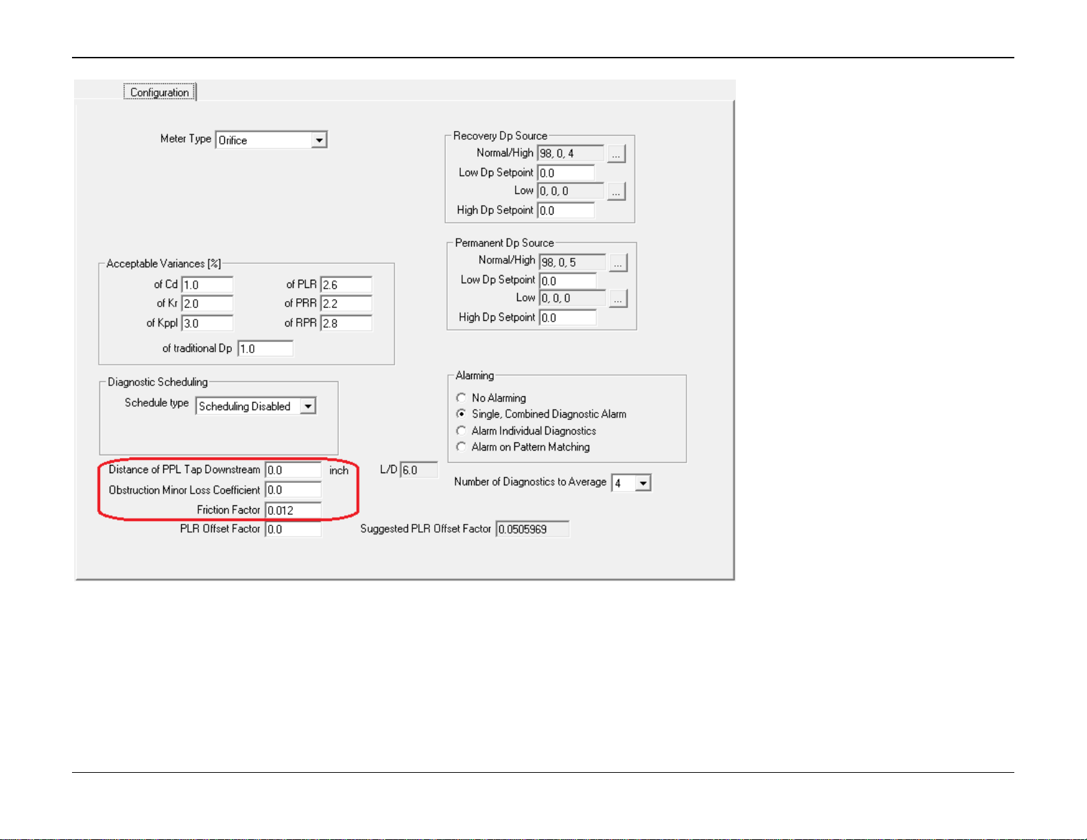
DP – Prognosis FC User Manual (for ROC800-Series)
Issued January-2017 Reference 67
Another option is to “zero the meter”. This is done as follows:
Insure (via inspection and calibration) that the meter is performing to specification
Observe the Suggested PLR Offset Factor value displayed in the DP Diagnostic Program’s Configuration tab
Enter the suggested value into the PLR Offset Factor parameter on the DP Diagnostic Program’s Configuration tab
Apply changes
Page 72

DP – Prognosis FC User Manual (for ROC800-Series)
For customer service and technical support,
visit www.EmersonProcess.com/Remote/Support.
Global Headquarters,
North America, and Latin America:
Emerson Automation Solutions
Remote Automation Solutions
6005 Rogerdale Road
Houston, TX 77072 U.S.A.
T +1 281 879 2699 | F +1 281 988 4445
www.EmersonProcess.com/Remote
© 2017 Remote Automation Solutions, a business unit of Emerson Automation Solutions. All
rights reserved.
This publication is for informational purposes only. While every effort has been made to ensure
accuracy, this publication shall not be read to include any warranty or guarantee, express or
implied, including as regards the products or services described or their use or applicability.
Remote Automation Solutions (RAS) reserves the right to modify or improve the designs or
specifications of its products at any time without notice. All sales are governed by RAS terms
and conditions which are available upon request. RAS accepts no responsibility for proper
selection, use or maintenance of any product, which remains solely with the purchaser and/or
end-user.
Europe:
Emerson Automation Solutions
Remote Automation Solutions
Unit 8, Waterfront Business Park
Dudley Road, Brierley Hill
Dudley UK DY5 1LX
T +44 1384 487200 | F +44 1384 487258
Middle East/Africa:
Emerson Automation Solutions
Remote Automation Solutions
Emerson FZE
P.O. Box 17033
Jebel Ali Free Zone – South 2
Dubai U.A.E.
T +971 4 8118100 | F +971 4 8865465
Asia-Pacific:
Emerson Automation Solutions
Remote Automation Solutions
1 Pandan Crescent
Singapore 128461
T +65 6777 8211| F +65 6777 0947
Remote Automation Solutions
 Loading...