

Page 1

Part Number D301220X412
February 2022
Config600™ Configuration Software User Manual
Remote Automation Solutions
Page 2

Config600 Configuration Software User Manual
System Training
A well-trained workforce is critical to the success of your operation. Knowing how to
correctly install, configure, program, calibrate, and trouble-shoot your Emerson equipment
provides your engineers and technicians with the skills and confidence to optimize your
investment. Remote Automation Solutions offers a variety of ways for your personnel to
acquire essential system expertise. Our full-time professional instructors can conduct
classroom training at several of our corporate offices, at your site, or even at your regional
Emerson office. You can also receive the same quality training via our live, interactive
Emerson Virtual Classroom and save on travel costs. For our complete schedule and further
information, contact the Remote Automation Solutions Training Department at +1-800-3388158 or email us at education@emerson.com.
ii Revised February 2022
Page 3

Config600 Configuration Software User Manual
Contents
Chapter 1 – Introduction 1-1
1.1 Configuration Updates .................................................................................................... 1-1
1.2 Scope of Manual ............................................................................................................. 1-2
1.3 Software Basics .............................................................................................................. 1-3
1.4 Installing Config600 ......................................................................................................... 1-5
1.5 Accessing Config600 ...................................................................................................... 1-9
1.6 Activating Config600 ....................................................................................................... 1-9
1.7 Additional Technical Information ................................................................................... 1-11
Chapter 2 – PCSetup Editor 2-1
2.1 Create a New Configuration ............................................................................................ 2-1
2.1.1 Name the Configuration (Step 1 of 6) ................................................................ 2-2
2.1.2 Select Measurement Units (Step 2 of 6) ........................................................... 2-3
2.1.3 Specify Modules (Step 3 of 6) ........................................................................... 2-4
2.1.4 Specify Stations (Step 4 of 6) ............................................................................ 2-5
2.1.5 Define Streams (Step 5 of 6) ............................................................................. 2-8
2.1.6 Select Communications (Step 6 of 6) .............................................................. 2-15
2.2 Analyse a Configuration (System Graphic) ................................................................... 2-17
2.3 Open an Existing Configuration (PCSetup Editor) ......................................................... 2-23
2.3.1 Navigating the PCSetup Editor........................................................................ 2-25
2.3.2 The Icon Bar.................................................................................................... 2-26
2.4 The Menu Bar ............................................................................................................... 2-27
2.5 Managing Configurations .............................................................................................. 2-28
2.5.1 Save a Configuration ....................................................................................... 2-28
2.5.2 Regenerate a Configuration ............................................................................ 2-28
2.6 Display Editor ................................................................................................................ 2-29
2.7 Config Transfer Utility .................................................................................................... 2-29
2.8 Config Organiser Utility ................................................................................................. 2-29
Chapter 3 – System Setup 3-1
3.1 Versions .......................................................................................................................... 3-2
3.2 Units ................................................................................................................................ 3-3
3.2.1 Supported Units ................................................................................................ 3-4
3.3 Reports............................................................................................................................ 3-6
3.3.1 General Reports ................................................................................................ 3-7
3.3.2 Base Time Reports ........................................................................................... 3-8
3.3.3 Default Reports ................................................................................................. 3-9
3.3.4 Report History ................................................................................................... 3-9
3.3.5 Adding a General Report to a Configuration ..................................................... 3-9
3.3.6 User Reports ................................................................................................... 3-11
3.3.7 Adding a Base Time Report to a Configuration ............................................... 3-11
3.3.8 Managing Configuration Reports..................................................................... 3-13
3.4 Totalisations .................................................................................................................. 3-14
3.5 Time .............................................................................................................................. 3-16
Chapter 4 – I/O and Comms Configuration 4-1
4.1 Discrete (Digital) Inputs (DI) ............................................................................................ 4-2
4.1.1 Assigning Discrete (Digital) Inputs .................................................................... 4-2
4.1.2 Editing Discrete (Digital) Inputs ......................................................................... 4-3
4.1.3 Adding Discrete (Digital) Inputs ......................................................................... 4-4
4.2 Discrete (Digital) Outputs (DO) ....................................................................................... 4-5
4.2.1 Assigning Discrete (Digital) Outputs .................................................................. 4-5
Revised February 2022 iii
Page 4

Config600 Configuration Software User Manual
4.3 Analog Inputs (AI) ........................................................................................................... 4-6
4.3.1 Assigning Analog Inputs (AI) ............................................................................. 4-6
4.3.2 Editing Analog Inputs (AI) ................................................................................. 4-7
4.3.3 Adding a New I/O Point ................................................................................... 4-15
4.4 Analog Outputs (AO) ..................................................................................................... 4-15
4.4.1 Editing Analog Outputs ................................................................................... 4-15
4.5 Density Inputs ............................................................................................................... 4-17
4.5.1 Assigning Density Input ................................................................................... 4-17
4.5.2 Editing Density Inputs ..................................................................................... 4-18
4.6 Turbine Inputs ............................................................................................................... 4-19
4.6.1 Assigning Turbine Inputs ................................................................................. 4-19
4.6.2 Editing Turbine Inputs ..................................................................................... 4-21
4.7 Pulse Outputs ................................................................................................................ 4-21
4.7.1 Assigning Pulse Outputs ................................................................................. 4-22
4.8 HART Modules .............................................................................................................. 4-22
4.8.1 Editing HART Settings .................................................................................... 4-23
4.9 PID Loop Settings ......................................................................................................... 4-23
4.9.1 Assigning PID Loops ....................................................................................... 4-24
4.9.2 Proportional Plus Integral and Derivative Action ............................................. 4-28
4.10 Communications Port .................................................................................................... 4-30
4.10.1 Editing a Communications Task ...................................................................... 4-30
4.10.2 Setting Up Peer-to-peer Options ..................................................................... 4-34
Chapter 5 – Station Configuration 5-1
5.1 Station Flowrate Limits .................................................................................................... 5-2
5.2 Station Averaging Temperature & Pressure .................................................................... 5-4
5.3 Station Secondary Units Setup ....................................................................................... 5-6
5.4 Station Flow Switching .................................................................................................... 5-8
5.5 Station Gas Composition............................................................................................... 5-10
5.6 Sampling ....................................................................................................................... 5-15
5.7 Prover Configuration Screens ....................................................................................... 5-18
5.7.1 Flow Balance Setup ........................................................................................ 5-18
5.7.2 Prover – Ball (Bi-Directional) (Liquid Only) ...................................................... 5-20
5.7.3 Prover – Compact (Liquid Only) ...................................................................... 5-33
5.7.4 Prover – Master Meter (Gas and Liquid) ......................................................... 5-45
Chapter 6 – Stream Configuration 6-1
6.1 Initial Configurations ........................................................................................................ 6-2
6.2 Common Stream Settings ............................................................................................... 6-4
6.2.1 General Settings ............................................................................................... 6-4
6.2.2 Flowrate ............................................................................................................ 6-5
6.2.3 Stream Secondary Units Setup ......................................................................... 6-7
6.2.4 Stream Flow Switching Setup ......................................................................... 6-10
6.2.5 Gas Component Flow Weighted Averaging (GC FWA) ................................... 6-11
6.2.6 Density Measurement ..................................................................................... 6-13
6.2.7 Block Valves.................................................................................................... 6-16
6.2.8 Time & Flow Weighted Averaging Methods .................................................... 6-18
6.3 Gas – Coriolis ................................................................................................................ 6-22
6.3.1 AGA8 (Compressibility) ................................................................................... 6-22
6.3.2 Gas CV (ISO6976 or GPA2172/ASTM D3588) ............................................... 6-25
6.3.3 Gas CV (AGA5)............................................................................................... 6-30
6.3.4 Stream Gas Composition ................................................................................ 6-31
6.3.5 Gas Properties ................................................................................................ 6-36
6.3.6 Ethylene .......................................................................................................... 6-39
6.3.7 Linearisation .................................................................................................... 6-40
6.3.8 Sampling ......................................................................................................... 6-42
6.3.9 Coriolis ............................................................................................................ 6-45
6.4 Gas – DP....................................................................................................................... 6-49
6.4.1 Downstream/Upstream Correction .................................................................. 6-49
6.4.2 Pipe Correction ............................................................................................... 6-52
iv Revised February 2022
Page 5

Config600 Configuration Software User Manual
6.4.3 AGA8 (Compressibility) ................................................................................... 6-55
6.4.4 ISO5167 (Mass Flowrate) ............................................................................... 6-58
6.4.5 ISOTR9464 ..................................................................................................... 6-61
6.4.6 V-Cone (Mass Flowrate) ................................................................................. 6-63
6.4.7 Annubar (Mass Flowrate) ................................................................................ 6-65
6.4.8 Pure Gas Air.................................................................................................... 6-67
6.4.9 Gas CV (ISO6976 or GPA2172/ASTM D3588) ............................................... 6-68
6.4.10 SGERG (Compressibility) ............................................................................... 6-73
6.4.11 NX19 (Compressibility) ................................................................................... 6-76
6.4.12 PTZ (Compressibility) ...................................................................................... 6-77
6.4.13 AGA3 (Volume or Mass Flowrate) ................................................................... 6-79
6.4.14 Stream Gas Composition ................................................................................ 6-81
6.4.15 Z Steam (Compressibility) ............................................................................... 6-85
6.4.16 GOST CV ........................................................................................................ 6-87
6.4.17 GOST Flow ..................................................................................................... 6-88
6.4.18 Gas Properties ................................................................................................ 6-91
6.4.19 DP Cell Input Conditioning .............................................................................. 6-94
6.5 Gas – Turbine ............................................................................................................. 6-111
6.5.1 AGA8 (Compressibility) ................................................................................. 6-111
6.5.2 Gas CV (ISO6976 or GPA2172/ASTM D3588) ............................................. 6-114
6.5.3 AGA7 (Gross Volume Flowrate) .................................................................... 6-118
6.5.4 Stream Gas Composition .............................................................................. 6-121
6.5.5 Gas Properties .............................................................................................. 6-125
6.5.6 Linearisation .................................................................................................. 6-128
6.6 Gas – Ultrasonic .......................................................................................................... 6-130
6.6.1 AGA8 (Compressibility) ................................................................................. 6-130
6.6.2 Gas CV (ISO6976 or GPA2172/ASTM D3588) ............................................. 6-133
6.6.3 AGA7 (Gross Volume Flowrate) .................................................................... 6-138
6.6.4 Stream Gas Composition (Gas Ultrasonic) ................................................... 6-140
6.6.5 Linearisation .................................................................................................. 6-144
6.6.6 Gas Properties (Gas Ultrasonic) ................................................................... 6-146
6.6.7 Ultrasonic Flow Setup ................................................................................... 6-149
6.6.8 Ultrasonic Control .......................................................................................... 6-152
6.6.9 QSonic Interface ........................................................................................... 6-154
6.6.10 SICK Control ................................................................................................. 6-155
6.7 Liquid – Coriolis ........................................................................................................... 6-158
6.7.1 Local Units .................................................................................................... 6-158
6.7.2 Linearisation .................................................................................................. 6-159
6.7.3 Sampling ....................................................................................................... 6-161
6.7.4 Observed Density Correction ........................................................................ 6-164
6.7.5 Standard Density Correction ......................................................................... 6-173
6.7.6 Base Sediment and Water (BSW) ................................................................. 6-179
6.7.7 Coriolis .......................................................................................................... 6-180
6.8 Liquid – Turbine .......................................................................................................... 6-183
6.8.1 Local Units .................................................................................................... 6-183
6.8.2 Linearisation .................................................................................................. 6-184
6.8.3 Observed Density Correction ........................................................................ 6-188
6.8.4 Standard Density Correction ......................................................................... 6-196
6.8.5 Base Sediment and Water (BSW) ................................................................. 6-202
6.9 Liquid - Ultrasonic ....................................................................................................... 6-204
6.9.1 Local Units .................................................................................................... 6-204
6.9.2 Linearisation .................................................................................................. 6-205
6.9.3 Observed Density Correction ........................................................................ 6-208
6.9.4 Standard Density Correction ......................................................................... 6-215
6.9.5 Base Sediment and Water (BSW) ................................................................. 6-221
6.9.6 Daniel Liquid Ultrasonic ................................................................................ 6-223
6.10 Modes of Operation ..................................................................................................... 6-226
6.10.1 Density Failure Modes .................................................................................. 6-227
Revised February 2022 v
Page 6

Config600 Configuration Software User Manual
Chapter 7 – Advanced Setup Configuration 7-1
7.1 Conversions/Constants ................................................................................................... 7-1
7.1.1 Editing Conversions/Constants ......................................................................... 7-1
7.2 Totals Descriptions .......................................................................................................... 7-2
7.2.1 Editing Totals Descriptors ................................................................................. 7-3
7.3 Alarms ............................................................................................................................. 7-3
7.3.1 Editing Alarms ................................................................................................... 7-4
7.3.2 Alarm Descriptions ............................................................................................ 7-6
7.4 Security ......................................................................................................................... 7-14
7.4.1 Editing Security ............................................................................................... 7-14
7.4.2 Editing/Deleting Passwords ............................................................................ 7-16
7.4.3 Data Item Security ........................................................................................... 7-17
7.4.4 PCSetup Editor Login ...................................................................................... 7-19
7.5 Displays/Webserver ...................................................................................................... 7-20
7.5.1 Editing Displays/Webserver ............................................................................ 7-21
7.6 Calc Explorer ................................................................................................................. 7-22
7.6.1 Calc Explorer Options ..................................................................................... 7-23
7.6.2 Adding an Item ................................................................................................ 7-24
7.6.3 Adding All Inputs ............................................................................................. 7-26
7.6.4 Adding All Outputs .......................................................................................... 7-27
7.6.5 Deleting Items ................................................................................................. 7-28
7.6.6 Saving as Bitmaps .......................................................................................... 7-29
Chapter 8 – System Editor 8-1
8.1 Accessing the System Editor ........................................................................................... 8-2
8.2 The S600+ Database ...................................................................................................... 8-3
8.2.1 Objects .............................................................................................................. 8-4
8.2.2 Tables ............................................................................................................... 8-5
8.3 Navigating the System Editor .......................................................................................... 8-5
8.3.1 Finding Objects ................................................................................................. 8-6
8.3.2 The System Editor Icon Bar .............................................................................. 8-6
8.3.3 Special Edit ....................................................................................................... 8-7
8.3.4 Edit Dialog ......................................................................................................... 8-8
8.3.5 Asterisks/No Asterisks ...................................................................................... 8-9
8.4 General Guidelines ....................................................................................................... 8-10
Chapter 9 – Config Transfer 9-1
9.1 Connecting to the S600+ ................................................................................................. 9-2
9.1.1 Connecting via Serial Cable .............................................................................. 9-2
9.1.2 Connecting via TCP/IP ...................................................................................... 9-2
9.1.3 Enabling the PC Setup Link .............................................................................. 9-2
9.1.4 Checksum Security ........................................................................................... 9-3
9.2 Accessing Config Transfer .............................................................................................. 9-3
9.3 Communications Settings for Transfer ............................................................................ 9-4
9.3.1 Setting Communication Parameters .................................................................. 9-4
9.4 Send Configuration ......................................................................................................... 9-6
9.4.1 Sending a Configuration .................................................................................... 9-6
9.4.2 Manually Adding a Configuration File to be Transferred ................................... 9-7
9.5 Receive Configuration ..................................................................................................... 9-8
9.5.1 Receiving a Configuration ................................................................................. 9-8
9.6 Log Transfers .................................................................................................................. 9-9
9.6.1 Logging a Transfer ............................................................................................ 9-9
9.7 CFX Licensing ............................................................................................................... 9-10
9.7.1 Transferring a License .................................................................................... 9-10
9.7.2 Removing a License ........................................................................................ 9-12
vi Revised February 2022
Page 7

Config600 Configuration Software User Manual
Chapter 10 – Remote Front Panel 10-1
10.1 Configuring Your PC without a Native Serial Comm Port .............................................. 10-1
10.1.1 Changing the Port on Your USB Communications Port .................................. 10-2
10.2 Configuring Your PC with a Native Serial Comm Port ................................................... 10-3
10.3 Configuring the S600+ to Use the Remote Front Panel ................................................ 10-4
10.4 Accessing the Remote Front Panel ............................................................................... 10-7
10.4.1 Remote Front Panel Startup Menu .................................................................. 10-7
10.4.2 Disabling the Remote Front Panel .................................................................. 10-8
10.4.3 Restoring the Remote Front Panel .................................................................. 10-9
Chapter 11 – Remote Archive Uploader 11-1
11.1 Accessing the Remote Archive Uploader ...................................................................... 11-2
11.2 Automatic Archive Polling.............................................................................................. 11-2
11.2.1 Configure Automatic Polling ............................................................................ 11-2
11.2.2 Add or Edit an Automatic Poll.......................................................................... 11-4
11.2.3 Enable Automatic Polling ................................................................................ 11-6
11.3 Manual Archive Polling .................................................................................................. 11-6
11.3.1 Configuring Config600 Communications ......................................................... 11-7
11.3.2 Reload Tree .................................................................................................... 11-8
11.3.3 Upload All Reports / Upload New Reports .................................................... 11-10
11.4 Viewing Reports .......................................................................................................... 11-11
11.4.1 Report Archive .............................................................................................. 11-11
11.5 Saving ......................................................................................................................... 11-12
11.5.1 Directory Settings (File Locations) ................................................................ 11-12
11.5.2 File Settings .................................................................................................. 11-13
11.5.3 Save As ......................................................................................................... 11-14
11.5.4 Folder Formats .............................................................................................. 11-15
11.5.5 Data Integrity ................................................................................................. 11-17
11.6 Printing the Report ...................................................................................................... 11-18
11.6.1 Print ............................................................................................................... 11-18
11.6.2 Print Preview ................................................................................................. 11-18
11.6.3 Print Setup .................................................................................................... 11-19
11.7 Abort Transfer ............................................................................................................. 11-20
Chapter 12 – Report Editor 12-1
12.1 Accessing the Report Editor .......................................................................................... 12-2
12.1.1 Via PCSetup.................................................................................................... 12-2
12.1.2 Via Report Editor ............................................................................................. 12-3
12.1.3 Report Names ................................................................................................. 12-5
12.2 Using the Report Editor ................................................................................................. 12-6
12.2.1 Adding a Data Point ........................................................................................ 12-7
12.2.2 Editing a Data Point ........................................................................................ 12-9
12.2.3 Adding Report Lines ........................................................................................ 12-9
12.2.4 Deleting Report Lines .................................................................................... 12-10
Chapter 13 – Display Editor 13-1
13.1 Accessing the Display Editor ......................................................................................... 13-1
13.2 Navigating the Display Editor ........................................................................................ 13-2
13.3 Editing the Display Editor .............................................................................................. 13-3
13.3.1 Insert Menu ..................................................................................................... 13-5
13.3.2 Insert/Append Page ........................................................................................ 13-5
13.3.3 Edit Line .......................................................................................................... 13-5
13.3.4 Translate ......................................................................................................... 13-7
13.3.5 Save ................................................................................................................ 13-8
13.3.6 Menu/Page Clipboard ..................................................................................... 13-8
Revised February 2022 vii
Page 8

Config600 Configuration Software User Manual
13.4 Regenerating Displays .................................................................................................. 13-8
Chapter 14 – Modbus Editor 14-1
14.1 Supported Function Codes............................................................................................ 14-1
14.2 Accessing the Modbus Editor ........................................................................................ 14-2
14.3 Using the Modbus Editor ............................................................................................... 14-2
14.4 Map Properties .............................................................................................................. 14-3
14.4.1 Insert a Data Point .......................................................................................... 14-5
14.4.2 Quick Insert ..................................................................................................... 14-6
14.4.3 Insert Special .................................................................................................. 14-6
14.4.4 Insert Special .................................................................................................. 14-7
14.4.5 Delete a Data Point ......................................................................................... 14-8
14.4.6 Edit Modbus Format ........................................................................................ 14-8
14.4.7 Insert a Message........................................................................................... 14-10
14.4.8 Insert a Slave ................................................................................................ 14-12
14.5 Regenerating Maps ..................................................................................................... 14-12
Chapter 15 – LogiCalc Editor 15-1
15.1 Accessing the LogiCalc Editor ....................................................................................... 15-2
15.1.1 LogiCalc Tips .................................................................................................. 15-4
15.1.2 Starting a LogiCalc .......................................................................................... 15-5
15.2 Creating a LogiCalc ....................................................................................................... 15-5
15.2.1 Variables ......................................................................................................... 15-6
15.2.2 LogiCalc Loops ............................................................................................... 15-7
15.2.3 LogiCalc Constants ......................................................................................... 15-8
15.2.4 Connecting to Data Items ................................................................................ 15-9
15.2.5 If/Then/Endif .................................................................................................. 15-11
15.2.6 Special Functions .......................................................................................... 15-12
15.2.7 Saving and Compiling a LogiCalc ................................................................. 15-13
15.2.8 Running a LogiCalc in Simulation Mode ....................................................... 15-14
15.3 Installing a LogiCalc on the S600+ .............................................................................. 15-15
15.3.1 Remotely Debugging a LogiCalc ................................................................... 15-16
15.4 LogiCalc Examples ..................................................................................................... 15-16
15.4.1 Perform PTZ Calculations ............................................................................. 15-17
15.4.2 Convert Temperature Units ........................................................................... 15-18
15.4.3 Convert Density Units to Kgm3 ..................................................................... 15-18
15.4.4 Convert Density Units from Kgm3 ................................................................. 15-19
15.4.5 Perform PTZ Calculations and Convert Units................................................ 15-20
15.4.6 Perform PTZ Calculations on All Streams ..................................................... 15-22
15.5 LogiCalc Lanuage Specifications ................................................................................ 15-23
15.5.1 LogiCalc Statements ..................................................................................... 15-23
15.5.2 Built-In Functions .......................................................................................... 15-26
15.5.3 Alarms ........................................................................................................... 15-28
Appendix A – Glossary A-1
Appendix B – Proving B-1
B.1 Bi-Directional (Ball) Prover – Liquid Only ....................................................................... B-2
B.1.1 Inputs/Outputs .................................................................................................. B-3
B.1.2 Communications .............................................................................................. B-3
B.1.3 Pulse Measurement ......................................................................................... B-4
B.1.4 Sphere Switch Interface ................................................................................... B-5
B.1.5 Valve Interface ................................................................................................. B-8
B.1.6 Prove Sequence and Control ........................................................................... B-9
B.1.7 Prover Run Control Stages ............................................................................ B-20
B.1.8 Prove/Stream Data ......................................................................................... B-28
B.1.9 Prove Reports ................................................................................................ B-30
viii Revised February 2022
Page 9

Config600 Configuration Software User Manual
B.1.10 Proving Calculations ...................................................................................... B-31
B.2 Compact Prover – Liquid Only ..................................................................................... B-39
B.2.1 Inputs/Outputs ................................................................................................ B-40
B.2.2 Communications ............................................................................................ B-41
B.2.3 Pulse Measurement ....................................................................................... B-42
B.2.4 Proving Control Signal Timing ........................................................................ B-42
B.2.5 Prove Sequence and Control ......................................................................... B-44
B.2.6 Prover Run Control Stages ............................................................................ B-54
B.2.7 Run Stage Abort Index ................................................................................... B-60
B.2.8 Run Stage Calculation Index .......................................................................... B-61
B.2.9 Prove/Stream Data ......................................................................................... B-61
B.2.10 Prove Reports ................................................................................................ B-63
B.2.11 Proving Calculations ...................................................................................... B-64
B.3 Master Meter Prover – Gas and Liquid ........................................................................ B-73
B.3.1 Master Meter/Stream combinations ............................................................... B-75
B.3.2 Inputs/Outputs ................................................................................................ B-76
B.3.3 Communications ............................................................................................ B-76
B.3.4 Pulse Measurement ....................................................................................... B-76
B.3.5 Prove Sequence and Control ......................................................................... B-77
B.3.6 Prover Run Control Stages ............................................................................ B-86
B.3.7 Prove/Stream Data ......................................................................................... B-92
B.3.8 Prove Reports ................................................................................................ B-93
B.3.9 Proving Calculations ...................................................................................... B-95
Appendix C – Batching C-1
C.1 Batching Overview ......................................................................................................... C-2
C.1.1 Product Table ................................................................................................... C-2
C.1.2 Station Batch Setup ......................................................................................... C-8
C.1.3 Product Interface Detection ............................................................................ C-14
C.1.4 Slops Handling Examples .............................................................................. C-17
C.2 Batch Sequence and Control ....................................................................................... C-18
C.2.1 Batch Sequence Stages ................................................................................. C-19
C.2.2 Retrospective Batch Totals ............................................................................ C-28
C.2.3 Batch Alarms .................................................................................................. C-29
C.2.4 Batch Ticket ................................................................................................... C-29
C.3 Batch Recalculation ..................................................................................................... C-31
C.3.1 Displays ......................................................................................................... C-31
C.3.2 Batch Ticket ................................................................................................... C-35
C.3.3 Recalculating Batches .................................................................................... C-37
C.4 Flow Switching ............................................................................................................. C-46
C.4.1 Station Flow Switching Setup ......................................................................... C-46
C.4.2 Stream Flow Switching Setup ........................................................................ C-48
C.4.3 Flow Switching Algorithms ............................................................................. C-49
C.4.4 Alarms ............................................................................................................ C-52
C.5 Batch Stack .................................................................................................................. C-52
C.5.1 Configuring the Batch Stack Through the PCSetup Editor ............................. C-53
C.5.2 Configuring the Batch Stack with the System Editor ...................................... C-55
C.5.3 Configuring the Batch Stack through the Front Panel Display ....................... C-57
C.5.4 Slot Edit Commands (Front Panel Display) .................................................... C-58
C.5.5 Configuring the Batch Stack from the Webserver .......................................... C-63
C.5.6 Slot Edit Commands (Webserver) .................................................................. C-64
C.6 Basic Batching Setup ................................................................................................... C-68
Appendix D – Field Calibration D-1
D.1 Analogue Input Calibration ............................................................................................. D-1
D.1.1 Calibration Control Requirements .................................................................... D-2
D.1.2 Linear Two-point ADC Device Calibration ........................................................ D-3
D.1.3 Non-linear Three-point Curve-fit ADC Device Calibration ................................ D-6
D.1.4 Non-linear Three-point Curve Calibration Control Mechanism ......................... D-7
D.1.5 Offset PRT Device Calibration ......................................................................... D-8
Revised February 2022 ix
Page 10

Config600 Configuration Software User Manual
D.1.6 Linear Two-point Device PRT Calibration ........................................................ D-8
D.1.7 Non-linear Three-point Curve-Fit PRT Device Calibration ............................... D-9
D.2 Analogue Output Calibration ........................................................................................ D-10
D.2.1 Calibration Control Requirements .................................................................. D-10
D.2.2 DAC Device Calibration ................................................................................. D-11
Appendix E – S600+ Database Objects and Fields E-1
E.1 Database Objects ........................................................................................................... E-2
E.1.1 ADC ................................................................................................................. E-2
E.1.2 ALARM ............................................................................................................. E-3
E.1.3 ALARMHIST..................................................................................................... E-3
E.1.4 ARRTXT ........................................................................................................... E-3
E.1.5 CALCALMITEM................................................................................................ E-4
E.1.6 CALCTAB ........................................................................................................ E-5
E.1.7 CONFTAB ........................................................................................................ E-6
E.1.8 CUMTOT .......................................................................................................... E-6
E.1.9 DACOUT .......................................................................................................... E-6
E.1.10 DIGIO ............................................................................................................... E-6
E.1.11 DOSETUP ........................................................................................................ E-7
E.1.12 DPCELL ........................................................................................................... E-7
E.1.13 EVENTHIST ..................................................................................................... E-8
E.1.14 FREQT ............................................................................................................. E-8
E.1.15 HART ............................................................................................................... E-8
E.1.16 HARTTAB ...................................................................................................... E-10
E.1.17 IOASSIGN ...................................................................................................... E-10
E.1.18 KPINT ............................................................................................................ E-10
E.1.19 KPINTARR ..................................................................................................... E-10
E.1.20 KPREAL ......................................................................................................... E-12
E.1.21 KPREALARR ................................................................................................. E-12
E.1.22 KPSTRING ..................................................................................................... E-13
E.1.23 LOG ............................................................................................................... E-13
E.1.24 MULTI ............................................................................................................ E-14
E.1.25 PID ................................................................................................................. E-14
E.1.26 PIP ................................................................................................................. E-14
E.1.27 POP ............................................................................................................... E-14
E.1.28 PRDTOT ........................................................................................................ E-14
E.1.29 PRT ................................................................................................................ E-15
E.1.30 PRV_CTL ....................................................................................................... E-16
E.1.31 REP00 – REP39 ............................................................................................ E-17
E.1.32 SECURITY ..................................................................................................... E-17
E.1.33 SYSOBJ ......................................................................................................... E-17
E.1.34 TASK .............................................................................................................. E-17
E.1.35 TOTTAB ......................................................................................................... E-17
E.2 Database Fields ........................................................................................................... E-18
E.2.1 Alarm Text Tables .......................................................................................... E-19
E.2.2 Batching/Totalisation ...................................................................................... E-19
E.2.3 DIGIO Setup Table ......................................................................................... E-19
E.2.4 DP Stack Type ............................................................................................... E-19
E.2.5 DP Live/Check Mode Selection ...................................................................... E-19
E.2.6 DP Cut Off Mode ............................................................................................ E-19
E.2.7 Event History Type ......................................................................................... E-19
E.2.8 HART Poll Format .......................................................................................... E-20
E.2.9 HART Master Mode ....................................................................................... E-20
E.2.10 I/O (P144) PID Type ....................................................................................... E-20
E.2.11 Prover (P154) Dual Chronometry Switch Pair ................................................ E-20
E.2.12 Prover (P154) Type ........................................................................................ E-21
E.2.13 Password Tables ............................................................................................ E-21
E.2.14 Truth Tables ................................................................................................... E-21
E.2.15 Turbine Meter Setup Tables ........................................................................... E-21
E.3 Mode Tables ................................................................................................................ E-21
E.3.1 ADC/PRT/HART Modes (MODE TAB PLANTI/O) .......................................... E-21
x Revised February 2022
Page 11

Config600 Configuration Software User Manual
E.3.2 CALC/ALM Auto Switch Modes...................................................................... E-22
E.3.3 CALC/ALM modes (MODE TAB CALC) ......................................................... E-22
E.3.4 Density Transducer Modes (MODE TAB DENS IP) ....................................... E-22
E.3.5 DP Modes (MODE TAB DP STACK) ............................................................. E-22
E.3.6 HART Modes (MODE TAB PLANTI/O) .......................................................... E-23
Appendix F – Peer-to-Peer Link Communications F-1
F.1 Peer-to-Peer Link Input Functionality ............................................................................. F-1
F.2 Enabling the Peer-to-Peer Link ...................................................................................... F-3
F.2.1 Configuring the Peer-to-Peer Link .................................................................... F-4
F.3 Critical Data .................................................................................................................... F-9
F.3.1 Passing an Object from the Duty to the Standby S600+ ................................ F-13
F.3.2 Period Object Transfer ................................................................................... F-16
F.4 Automatic Failover ....................................................................................................... F-16
F.4.1 Configuring the S600+ for Automatic Failover ................................................ F-18
F.5 External / Custom Failover Modes ............................................................................... F-24
F.6 Displays........................................................................................................................ F-26
F.6.1 Control Displays ............................................................................................. F-26
F.6.2 Feed-back Displays ........................................................................................ F-27
F.6.3 Option Displays .............................................................................................. F-28
F.7 Downloading and Verifying the Peer to Peer Link ........................................................ F-28
Appendix G – Firewall G-1
G.1 Rules File ....................................................................................................................... G-1
G.1.1 *Filter Keyword ................................................................................................. G-2
G.1.2 Default Policies ................................................................................................ G-2
G.1.3 User Defined Chains ........................................................................................ G-2
G.2 Adding Rules to the Chain.............................................................................................. G-3
G.2.1 Applying a Rule to a Range of IPs ................................................................... G-3
G.2.2 Inverting a Rule ................................................................................................ G-3
G.2.3 After Checking the Rules ................................................................................. G-3
G.2.4 Committing the Rules ....................................................................................... G-3
G.3 Operational Behaviour ................................................................................................... G-3
Appendix H – CFX Reporting H-1
H.1 Adding CFX Report Functionality to a Configuration File ............................................... H-1
H.2 Enabling CFX at the Stream Level ................................................................................. H-3
H.3 Changing CFX Settings from Config600 ........................................................................ H-4
H.4 Regenerating the CFX Report Template ........................................................................ H-5
H.5 Generating a CFX Report from the Web Browser .......................................................... H-5
H.6 Understanding the CFX File Structure ........................................................................... H-8
Appendix I – Network Printing I-1
I.1 Overview .......................................................................................................................... I-1
I.1.1 Supported Printers ............................................................................................. I-2
I.1.2 Supported Paper Sizes ...................................................................................... I-2
I.2 Configuring Printers from PCSetup .................................................................................. I-2
I.3 Configuring Printers from the S600+ ................................................................................ I-4
I.3.1 Configuring at Runtime ...................................................................................... I-4
I.3.2 Printer Options ................................................................................................... I-4
Revised February 2022 xi
Page 12

Config600 Configuration Software User Manual
I.4 Printing Retries ................................................................................................................. I-5
I.5 Editing Report Line Lengths ............................................................................................. I-5
I.6 Network Printing Alarms ................................................................................................... I-8
Appendix J – Sampling J-1
J.1 Overview ......................................................................................................................... J-1
J.2 Input / Outputs ................................................................................................................. J-1
J.2.1 Sampler Output ................................................................................................. J-2
J.2.2 Sampler Can Select Output .............................................................................. J-2
J.3 Sampling Options ............................................................................................................ J-2
J.3.1 Sampler Method ................................................................................................ J-2
J.3.2 Sampler Mode ................................................................................................... J-3
J.3.3 Can Fill Indicator ............................................................................................... J-4
J.3.4 Auto Disable ...................................................................................................... J-4
J.3.5 Auto Restart ...................................................................................................... J-4
J.4 Sampling Sequence ........................................................................................................ J-5
J.5 Sampling Alarms ........................................................................................................... J-10
J.6 Sampling Displays ......................................................................................................... J-11
J.7 Sampling – System Editor ............................................................................................. J-13
Appendix K – Chromatographs K-1
K.1 Station/Stream Assignment ............................................................................................ K-2
K.1.1 Single Metering Stream with No Station ........................................................... K-2
K.1.2 Multiple Metering Streams Assigned to a Common Station ............................. K-2
K.1.3 Individual Metering Streams Assigned to a Chromatograph ............................ K-2
K.1.4 Multiple Metering Streams Separately Assigned to a Stream .......................... K-3
K.1.5 Multiple S600+s Connected to a Single Chromatograph.................................. K-3
K.2 Inputs and Outputs ......................................................................................................... K-3
K.2.1 Main Setup Parameters ................................................................................... K-4
K.2.2 Component Set Selection Inputs ...................................................................... K-4
K.2.3 Component Set Selection Outputs ................................................................... K-4
K.2.4 Telemetry Configuration Parameters ............................................................... K-4
K.2.5 Telemetry Outputs ............................................................................................ K-5
K.3 Configuration Type: Keypad Mole Percentage Set Only ................................................ K-6
K.4 Configuration Type: 2551/2350 Euro ............................................................................. K-7
K.4.1 Telemetry Stages ............................................................................................. K-7
K.4.2 Determining the Mole Percentage Set ........................................................... K-11
K.4.3 Handling Operator Commands....................................................................... K-11
K.5 Configuration Type: 2251/2350 USA ............................................................................ K-11
K.5.1 Telemetry Stages ........................................................................................... K-12
K.5.2 Determining the Mole Percentage Set ........................................................... K-13
K.5.3 Handling Operator Commands....................................................................... K-14
K.6 Configuration Type: Siemens ....................................................................................... K-14
K.6.1 Telemetry Stages ........................................................................................... K-14
K.6.2 Determining the Mole Percentage Set ........................................................... K-16
K.6.3 Handling Operator Commands....................................................................... K-17
K.7 Configuration Type: Generic ........................................................................................ K-17
K.7.1 Telemetry Stages ........................................................................................... K-17
K.7.2 Determining the Mole Percentage Set ........................................................... K-19
K.7.3 Handling Operator Commands....................................................................... K-20
K.8 Configuration Type: Download from Supervisory System ............................................ K-20
K.9 Normalisation, Additionals, and C+6 Handling ............................................................. K-20
K.9.1 Normalisation ................................................................................................. K-20
K.9.2 Application of Additionals ............................................................................... K-21
K.9.3 C6+ Handling ................................................................................................. K-21
K.9.4 C6+ Handling (SIM 2251 Method) .................................................................. K-21
K.9.5 C7+ Handling ................................................................................................. K-22
K.9.6 No C6+ or C7+ Handling ................................................................................ K-23
K.10 Alarms, Displays, Reports, and Maps .......................................................................... K-23
K.10.1 Alarms ............................................................................................................ K-23
xii Revised February 2022
Page 13

Config600 Configuration Software User Manual
K.10.2 Displays ......................................................................................................... K-23
K.10.3 Reports .......................................................................................................... K-24
K.10.4 Modbus Maps................................................................................................. K-27
Index Index-1
Revised February 2022 xiii
Page 14

Config600 Configuration Software User Manual
[This page is intentionally left blank.]
xiv Revised February 2022
Page 15

Chapter 1 – Introduction
Caution
In This Chapter
1.1 Configuration Updates ....................................................................... 1-1
1.2 Scope of Manual ............................................................................... 1-2
1.3 Software Basics ................................................................................. 1-3
1.4 Installing Config600 ........................................................................... 1-5
1.5 Accessing Config600 ......................................................................... 1-9
1.6 Activating Config600 ......................................................................... 1-9
1.7 Additional Technical Information ..................................................... 1-11
This manual describes how to use the Config600™ configuration
software suite of editors (referred to as “Config600”) to configure the
FloBoss™ S600+ Flow Computer (referred to as “S600+”). The
software runs on a personal computer (PC) running Microsoft®
Windows
or 64-bit), Windows 10 (32-bit or 64-bit), or Server 2003. Refer to the
technical specification Config™ 600 Configuration Software
(Config600).
This manual discusses configuring S600+ options, including
calculations; input/output (I/O); communications; Proportional,
Integral, and Derivative (PID) loops; stations; streams; displays;
Modbus maps; LogiCalc programming; and reports.
®
2000 with Service Pack 2, XP, Vista®, Windows 7 (32-bit
Config600 Configuration Software User Manual
Use this manual in conjunction with the FloBoss S600+ Flow Manager
Instruction Manual (part D301150X412).
When implementing control using this product, observe best industry
practices as suggested by applicable and appropriate environmental,
health, and safety organizations.
This chapter details the structure of this manual and provides an
overview of the Config600 software.
1.1 Configuration Updates
The S600+ CPU module has also been enhanced and now contains an
upgraded version of firmware. You can download existing
configurations from earlier versions of Config600 without change.
However, if you use the latest version of Config600 to modify an old
configuration, the configuration file upgrades and will work only with
version 8 and above. That means you can no longer use old versions of
Config600 to edit that configuration.
When you open an older configuration in the current version of
Config600, the following dialog box displays:
Revised February 2022 Introduction 1-1
Page 16

Config600 Configuration Software User Manual
Chapter
Description
Chapter 1
Defines the scope of the document, provides an
install the software.
Chapter 2
Describes the PCSetup Editor interface, the
and the System Graphic utility.
Chapter 3
Configuration
Describes the System Setup screens (Versions, Units,
the configuration wizard.
Chapter 4
Configuration
Describes the Input/Output (I/O) assignment screens,
task settings screen in the PCSetup Editor.
Chapter 5
Station Configuration
Describes the Station Settings screens in the PCSetup
Editor.
Chapter 6
Stream Configuration
Describes the Stream Settings screens in the PCSetup
Editor.
Chapter 7
Describes the Advanced Setup screens (Conversions,
Calc Explorer utility.
Chapter 8
Describes the advanced configuration editor, the
Note: This utility is available only with Config600 Pro.
Chapter 9
Describes the configuration transfer utility. Use this
configuration files from the host PC to the S600+.
PRO
If you click OK to upgrade, you cannot then use this configuration on
an S600+ which has firmware less that version 0.6.05. If you need to
use this configuration on older S600+ flow computers, click Close (
to end this process. We suggest you then re-create this configuration
using the most current version of Config600 or create a copy of the old
configuration.
1.2 Scope of Manual
Figure 1-1. Config Upgrade dialog
)
This manual contains the following chapters:
Introduction
PCSetup Editor
System Setup
I/O and Comms
Advanced Setup
Configuration
overview of the Config600 software, and details how to
configuration generator, how to save configurations,
Reports, and Totalisation) in the PCSetup Editor, and
the PID loop settings screens, and the communication
Totals Descriptors, Alarms, Security, and
Displays/Webserver) in the PCSetup Editor and the
System Editor
Config Transfer
1-2 Introduction Revised February 2022
System Editor (which includes Station Mapping).
utility to send new or modified files to the S600+ over
either a dedicated serial port or a TCP/IP connection.
Config Transfer also enables you to retrieve
Page 17

Config600 Configuration Software User Manual
Chapter
Description
Chapter 10
Describes how to set up the Remote Front Panel to
Panel)
Chapter 11
Uploader
Describes how to automatically upload all reports and
computer.
Chapter 12
Report Editor
Chapter 13
Display Editor
Describes the editor you use to customize the front
panel and webserver displays of the S600+.
Chapter 14
Modbus Editor
Chapter 15
Describes the editing tool for the LogiCalc programming
Note: This tool is available only with Config600 Pro.
Appendix A: Glossary
Provides definitions of acronyms and terms.
Appendix B: Proving
Provides a description of the three proving methods
compact, and master meter.
Appendix C: Batching
Describes the type of batch method you can use for
non-permanent flows or “start-stop” batching.
Appendix D: Field
Describes hardware calibration you perform after
analogue converter counts and current.
Appendix E: S600+
Provides an alphabetic listing of the database objects
Editor, Display Editor, and System Editor).
Appendix F: Peer-to-
Describes the bi-directional communications link
through the supervisory system.
Appendix G: Firewall
Provides information detailing the S600+ firewall to
keep out unwanted incoming network connections.
Appendix H: CFX
Provides information on creating Common File
eXchange (CFX) reports.
Appendix I: Network
Printing
Provides information on network printing options for the
S600+.
Index
Provides an alphabetic listing of items and topics
contained in this manual.
PRO
Remote Front Panel
Remote Archive
LogiCalc Editor
configure your S600+ and perform certain functions
from your PC.
Note: The Remote Front Panel requires part
S600+EXT (the licence key for Remote Front
alarms in the historical archive in the S600+ flow
Describes the report format editor.
Describes the Modbus map editor.
language.
Confi600 supports: bi-directional (and uni-directional),
1.3 Software Basics
Config600 software is a Microsoft Windows-based suite of tools that
enables you to configure and communicate with the S600+ using a host
PC. The software has three versions:
Calibration
Database Objects and
Fields
Peer Communications
production to determine the relationship between
you can access through the Connect Wizard (which is
part of the Report Editor, Modbus Editor, LogiCalc
between the A and B computers allowing the duty
S600+ to update the standby S600+ with any operator
changes made locally at the duty S600+ keypad or
Config600 Lite, which provides a basic set of tools designed to
help you modify existing configurations.
Config600 Lite Plus, which adds a tool to create configurations to
Config600 Lite.
Revised February 2022 Introduction 1-3
Page 18

Config600 Configuration Software User Manual
Tool
Config600 Lite
Config600 Lite Plus
Config600 Pro
PCSetup X X
X
Config Transfer
X X X
Report Editor X X
X
Modbus Editor X X
X
Display Editor X X
X
LogiCalc Editor
X
System Editor
X
Config Generator
X X
Remote Archive Uploader1
X X X
Remote Front Panel1
X X X
Version History
X X X
Config600 Pro, which provides a more powerful set of tools to
help you create and manage configurations.
Note: If you are new to the S600+, review Chapter 2, PCSetup
Editor. This section describes the basic steps involved in
configuring your S600+ for your application. You can then use
the PCSetup Editor (available in Config600 Pro) to edit
existing configurations.
Table 1-1 compares the tools available in each version.
Table 1-1. Config600 Tools
1
Remote Archive Uploader and Remote Front Panel are extended functions of Config600 which you must
license separately to use. Contact your sales representative for further information.
Using the PCSetup Editor in Config600, you define the initial S600+
configuration settings for gas, liquid, or prover applications. These
initial configurations include system setup, Input/Output (I/O) setup,
stations, and streams. You save these configurations to a configuration
directory on the host PC. Using the Config Transfer utility, you send
(“download”) the configuration to the S600+ through a serial or
Ethernet communications port. The download also stores the sent
configuration permanently in the S600+’s memory.
With Config600 Pro software, you can:
Use the Config Generator Wizard to create new configurations.
Use the Config Transfer utility to send or receive the
configuration to the S600+ through a serial or Ethernet
communications port. The exchange also stores the send
configuration permanently in the S600+’s memory.
Use the Display Editor to configure front panel/webserver
displays.
Use the LogiCalc Editor to configure LogiCalc applications.
1-4 Introduction Revised February 2022
Use the Modbus Editor to configure Modbus communications.
Use the PCSetup Editor to define the initial S600+ configuration
settings for gas, liquid, or prover applications. These initial
configurations include system setup, Input/Output setup, stations,
and streams. You save these configurations to a configuration
directory on the host PC.
Page 19

Config600 Configuration Software User Manual
Use the Remote Archive Uploader to automatically upload all
reports in the historical archive in the S600+ and manually upload
other types of files.
Use the Remote Front Panel to configure the S600+ to run from
the PC.
Use the Report Editor to generate system reports.
Use the System Editor to configure the S600+ database.
Use the Version History text file to view a change history
document that explains changes and updates to the Config600 and
S600+.
Note: To get help on a specific screen, press F1 or click Help. You
can also modify the size of the Config600 editor window by
clicking and dragging the lower right corner of the window.
When configuration panes have scroll bars, modify the window
size to make sure you can view all the configuration settings.
1.4 Installing Config600
Remote Automation Solutions distributes Config600 software either on
a CD-ROM or as a downloadable zipped file. You can install
Config600 software on a PC running Windows 2000 with Service Pack
2, XP, Vista®, Windows 7 (32-bit or 64-bit), Windows 10 (32-bit or
64-bit), or Server 2003.
Note: Refer to the product data sheets S600+ and Config600
To install Config600:
1. Place the Config600 installation CD-ROM in your PC’s CD or
DVD drive. The installation should begin automatically.
2. If the CD-ROM does not run automatically, click Start > Run.
When the Run dialog box opens, click Browse, navigate to the CDROM drive, and select setup.exe. Click Open. The system
completes the file location. Click OK in the Run dialog box.
(available https://www.emerson.com/en-us/catalog/emersonfloboss-s600) for complete product requirements and
specifications.
Note: If you are using a zipped executable file, download the file
to a temporary location (the installation program installs the
file in (C:\Users\<<USERNAME>>\Config600 3.3). Unzip
the file and click setup.exe.
The Installation Wizard screen displays, and determines whether
you have previously installed Config600.
3. If this is a new installation, the Config600 Welcome screen
displays, followed by a License Agreement screen.
Revised February 2022 Introduction 1-5
Page 20

Config600 Configuration Software User Manual
Figure 1-2. License Agreement
4. Review the license agreement and click I Agree to continue. A
Choose Components screen displays.
Figure 1-3. Choose Components
Note: Config600 Pro activation codes/licences are issued only to
those who successfully complete the RA901 Advanced
Config600 training course.
1-6 Introduction Revised February 2022
Page 21

Config600 Configuration Software User Manual
5. Select to install the version of Config600 you have purchased and
click Next. The installation wizard identifies the default destination
folder (C:\Users\<<USERNAME>>\Config600 3.3).
Note: Attendance at the Config600 Pro training class is required
to use Config600 Pro.
Figure 1-4. Install Location
6. Click Browse to select an alternative installation folder.
7. Click Install. As the installation proceeds, the installation wizard
displays a screen showing the progress of the installation.
Revised February 2022 Introduction 1-7
Page 22

Config600 Configuration Software User Manual
Figure 1-5. Installation Progress
8. When the installation completes, the wizard displays a completion
screen.
Figure 1-6. Installation Complete
9. Click Close to end the installation.
Note: You may need to restart your PC to complete the
installation.
1-8 Introduction Revised February 2022
Page 23

1.5 Accessing Config600
After you successfully install the Config600 software, you can access
the application suite either of two ways.
Create application–specific shortcut icons your desktop.
Select Start > All Programs > Config600 3.3 and select an
application from the menu.
Note: If you have installed the Lite or Lite Plus version, that
Config600 Configuration Software User Manual
option appears in the selection menu.
Figure 1-7. Config600 Menu
Which method you choose depends on personal preference. Proceed to
Chapter 2, PCSetup Editor, for further information on the PCSetup
utility.
1.6 Activating Config600
After you successfully install the software, you must next activate it.
The activation screen (see Figure 1-8) displays when you attempt to
open any of the Config600 component tools:
Note:
Revised February 2022 Introduction 1-9
Page 24

Config600 Configuration Software User Manual
Remote Archive Uploader can be used for a 30-day trial period
after which an activation license must be obtained.
There is no trial period available for Lite / Lite+ / Pro – an
activation license must be obtained before use.
Figure 1-8. Config600 Activation Screen
Click Email Codes to send a request to
CST.RASEurope@emerson.com for an activation code. The email
automatically captures your Site Code and Machine ID.
Note: Each installation of Config600 is unique. Each copy of
Config600 you install requires its own activation code.
Once you obtain an activation code, select Unlock application, enter
the code in the Activation Code field, and click Continue. The
Config600 utility you select opens.
Note: Config600 Pro activation codes/licences are issued only to
those who successfully complete the RA901 Advanced
Config600 training course.
1-10 Introduction Revised February 2022
Page 25

Config600 Configuration Software User Manual
If you need to move your copy of Config600 to a new PC, un-install
If you manually reset the clock on your PC, it is possible that
Document Name
Form Number
Part Number
FloBoss™ S600+ Flow Computer Instruction Manual
A6115
D301150X412
FloBoss™ S600+ Flow Computer Product Data Sheet
S600+
D301151X012
Config™ 600 Configuration Software Product Data Sheet
Config600
D301164X012
FloBoss™ S600+ Field Upgrade Guide
A6299
D301668X412
Re-installing
Config600
the software using PCSetup. The process generates a code you send to
CST.RASEurope@emerson.com. You still need to provide the unique
site code and machine ID.
Use the authorization code you receive in return to re-activate
Config600.
Changing the
PC Clock
Config600 may stop working and require you to re-authorize the
software. This is not a problem if you allow the PC software to
automatically accommodate changes for daylight saving time.
1.7 Additional Technical Information
Refer to the following technical documentation (available at
www.EmersonProcess.com/Remote) for additional and most-current
information.
Table 1-2. Additional Technical Information
Revised February 2022 Introduction 1-11
Page 26

Config600 Configuration Software User Manual
[This page is intentionally left blank.]
1-12 Introduction Revised February 2022
Page 27

Chapter 2 – PCSetup Editor
In This Chapter
2.1 Create a New Configuration .............................................................. 2-1
2.1.1 Name the Configuration (Step 1 of 6) ................................... 2-2
2.1.2 Select Measurement Units (Step 2 of 6) ............................... 2-3
2.1.3 Specify I/O (Step 3 of 6) ....................................................... 2-4
2.1.4 Specify Stations (Step 4 of 6) ............................................... 2-5
2.1.5 Define Streams (Step 5 of 6) ................................................ 2-8
2.1.6 Select Communications (Step 6 of 6) ................................. 2-15
2.2 Analyse a Configuration (System Graphic) ..................................... 2-17
2.3 Open an Existing Configuration (PCSetup Editor) ........................... 2-23
2.3.1 Navigating the PCSetup Editor ........................................... 2-25
2.3.2 The Icon Bar ....................................................................... 2-26
2.4 The Menu Bar.................................................................................. 2-27
2.5 Managing Configurations ................................................................ 2-28
2.5.1 Save a Configuration .......................................................... 2-28
2.5.2 Regenerate a Configuration ............................................... 2-28
2.6 Display Editor .................................................................................. 2-29
2.7 Config Transfer Utility ...................................................................... 2-29
2.8 Config Organiser Utility ................................................................... 2-29
Config600 Configuration Software User Manual
When you start Config600 Pro, the Welcome to Config600 screen
displays (see Figure 2-1). Using this screen, you can create a new
S600+ configuration, open an existing configuration, transfer data
between a PC and the S600+, access on-line help, or control whether
the Welcome screen displays when you start the software.
Figure 2-1. Config600 Welcome
2.1 Create a New Configuration
The Configuration Wizard provides several ways for you to create a
new configuration:
Revised February 2022 PCSetup Editor 2-1
Page 28

Config600 Configuration Software User Manual
Click the New icon on the PCSetup Editor’s toolbar.
Click Start > All Programs > Config600 3.3 > Config
Generator.
Click the icon next to the Create a new configuration option
from the PCSetup Editor’s Welcome to Config600 Screen (View >
Startup Screen).
Note: You can also start the Configuration Generator by selecting
File > New from the PCSetup screen. The Configuration
Generator is included in both the Config600 Pro and Config600
Lite Plus software suites.
The Configuration Generator is a wizard-based software assistant that
asks a series of questions to simplify the six-step process of creating a
new S600+ configuration file. The wizard also validates your
selections to prevent errors. Once you finish, the wizard saves the
configuration settings to a file. You can modify the configuration and
then send the configuration to the S600+.
2.1.1 Name the Configuration (Step 1 of 6)
Note: All screens in this section are examples intended to show all
possible options and do not represent actual configurations.
Use the first screen in the wizard (Figure 2-2) to provide a name and
brief description for the configuration file.
Figure 2-2. Configuration Generator, Step 1
1. Enter a name for the configuration. Keep the name short (up to 20
alphanumeric characters) for easy identification.
2-2 PCSetup Editor Revised February 2022
Page 29

Config600 Configuration Software User Manual
Note: This step is mandatory.
2. Enter a description for the configuration.
Note: The Configuration Generator displays the name you give
the file on the running configuration. This optional
description is for your information only.
3. Click Next.
2.1.2 Select Measurement Units (Step 2 of 6)
Use the second screen in the wizard (Figure 2-3) to set the units of
measurement for the configuration.
Figure 2-3. Configuration Generator, Step 2
1. Select the units of measurement the S600+ uses. Valid values are
Metric or Imperial. The default is Metric. Click to display
more values.
Caution
This choice affects how Config600 handles a number of options,
including the default ADC and PRT modes, maintenance mode
interlock, alarm latch mode, and others.
Note: You can modify this initial setting after you complete the
wizard.
2. Click Next.
Revised February 2022 PCSetup Editor 2-3
Page 30

Config600 Configuration Software User Manual
Module
Description
I/O Module (P144)
Each I/O module can handle up to two streams
module in each configuration.
HART Module (P188)
This module enables the S600+ to
module.
Prover Module
The Prover module provides the functions
in any configuration.
2.1.3 Specify Modules (Step 3 of 6)
Use the third screen in the wizard (Figure 2-4) to indicate the number
of I/O, optional HART, and optional prover modules installed in the
S600+ for this configuration.
Figure 2-4. Configuration Generator, Step 3
1. Click and to indicate the number and kinds of modules
physically installed in the S600+. The S600+ chassis can house up
to three modules:
and include both analog and digital I/O.
Note: You must include at least one I/O
communicate with HART® devices using the
HART protocol. Each HART module has 12
channels, and each channel can accept up to
eight devices. However, you cannot have more
than 50 devices attached to any one HART
(P154)
required for liquid prover applications. It is
mandatory if you select a prover as part of this
configuration.
Note: You can include only one Prover module
2-4 PCSetup Editor Revised February 2022
2. Click Next.
Page 31

Config600 Configuration Software User Manual
2.1.4 Specify Stations (Step 4 of 6)
Use the fourth screen in the wizard (Figure 2-5) to indicate the number
(up to two) and type (gas or liquid) of stations in the configuration. The
wizard defaults to one gas station.
You can define a maximum of two provers (ball, compact, or master
meter), one for each station.
Figure 2-5. Configuration Generator, Step 4
1. Indicate the number of stations (to a maximum of two) for this
configuration. Click or to add or delete stations.
2. Indicate whether the station handles Gas or Liquid. Click to
display additional values. The default value is Gas.
3. Click Options to display a list of default values for each type of
station. The station options for gas and liquid differ.
Note: As you modify these options, Config600 displays a
summary of the options you select.
Revised February 2022 PCSetup Editor 2-5
Page 32

Config600 Configuration Software User Manual
Option
Description
Densitometer/
Performs calculations using densitometer input at
the station.
Single Chromat/
No Chromat
Performs calculations using chromatograph
MM Prover/
Uses a Master Meter Prover.
supported.
Batching/
Performs station batch handling. Enable batch
reports and totals.
Flow Switching/
No Flow Switching
Balances the station flow by opening and closing
streams.
Sampling/
No Sampling
Performs single or twin can sampling.
Summary of
selected options
Figure 2-6. Gas Station Options Summary
For a Gas station, select the appropriate options. Config600
initially highlights default values.
No Densitometer
Dual Chromat/
No Prover
No Batching
input(s) at the station.
Note:
This option requires an associated metering
stream.
Only MM volume v Stream volume is
Note: As you select options, the Additional Options Selected
frame (at bottom of the Options screen) summarizes your
selections (see Figure 2-7).
2-6 PCSetup Editor Revised February 2022
Page 33

Summary
of selected
options
Config600 Configuration Software User Manual
Figure 2-7. Gas Station Options Summarized
For a Liquid station, select the appropriate options. Config600
initially highlights default values.
Figure 2-8. Liquid Station Options Summary screens
Revised February 2022 PCSetup Editor 2-7
Page 34

Config600 Configuration Software User Manual
Option
Description
Option1
Performs no liquid volume calculations at the
keypad input.
Option2
Measures header density but performs no liquid
volume calculations at the station.
Option3
Calculates station standard density using header
all station inputs.
Ball Prover
Uses a bi-directional or uni-directional prover.
provers.”
Compact Prover
Uses a Daniels
®
Compact Prover™
MM Prover
Stream Mass and MM Mass v Stream Mass.
No Prover
Indicates this station does not perform prover
runs.
Batching
Indicates if the station performs batch handling.
Enable batch reports and totals.
Flow Switching
Indicates if the station balances station flow by
opening and closing streams.
Sampling
No Sampling
Indicates if the station performs no sampling or
twin can sampling.
Product Table
Permits multiple product selection for pipeline
metering.
station. Station standard density is available as a
density with header temperature and pressure at
Note: Ball provers are also known as “pipe
Uses a master meter prover.
Note:
This option requires an associated metering
stream.
The following combinations are supported:
MM volume v Stream volume, MM volume v
No Batching
No Flow Switching
No Product Table
Note: As you select options, the graphic in the screen changes and
the Additional Options Selected frame (at the bottom of the
Options screen) summarizes your selections.
4. Click Additionals to include any optional calculations in the
configuration. Config600 opens a text box you use to record the
additional calculations.
5. Click OK when you finish adding optional calculations.
6. Click Next.
2.1.5 Define Streams (Step 5 of 6)
batching applications. Select No Product Table
to use a single product for continuous flow
2-8 PCSetup Editor Revised February 2022
Use the fifth screen in the wizard (Figure 2-9) to associate streams
and stations. You indicate the number of streams, the type of
stream (gas, liquid, or RTU), link the stream to a station, and select
stream options.
Page 35

Config600 Configuration Software User Manual
Notes:
For station summation of stream flowrates to work correctly, all
stations must have at least one stream configured.
Although you can define up to 10 streams, a standard S600+
chassis can hold only three I/O modules. Each I/O module only
has two dual-pulse inputs (2 turbines), so a standard S600+ can
support only six dual-pulse turbine streams. However, it could
support up to 10 single-pulse or 10 single-cell gas DPs.
Config600 uses the options you selected up to this point to
determine operational values, including stream flow rate, density,
flow weighted averages, and other specific values, for each type of
stream (gas, liquid, or RTU).
Note: The Graphic Preview button that appears on this screen
provides a graphic representation of your configuration.
Figure 2-9. Configuration Generator, Step 5
1. Click or to add and delete streams (up to six dual-pulse or ten
single-pulse). The screen initially displays only one stream.
Note: If you are configuring a prover application and require
remote streams, then set the number of streams to 0 and
select Next. You will then be prompted to select the
number of remote streams you require (up to 10).
2. Click to select a type (gas, liquid, or RTU) for each stream.
Revised February 2022 PCSetup Editor 2-9
Page 36
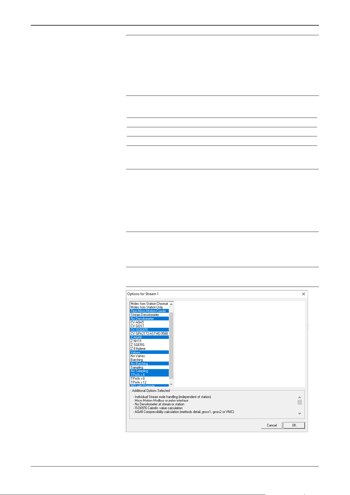
Config600 Configuration Software User Manual
Stream Type
Options
Liquid
Coriolis, Turbine, Ultrasonic
RTU
only
Note: So that S600+ flow computers can share information, you
must group similar types of streams together (that is, gas
with gas and liquid with liquid) and assign streams to
stations. Config600 displays a warning message at the
bottom of the screen and disables Next and Graphic
Preview. Until you resolve these errors you cannot
complete the configuration.
3. Click to select a meter to associate with each stream type.
Gas Coriolis, DP, Turbine, Ultrasonic
Standard (
option)
4. Click to select a station for each stream-and-meter combination.
Notes:
The RTU stream type essentially collects data for additional
I/O handling and has no metering function. Consequently, you
cannot associate an RTU stream with a specific metering
station. No Station is the appropriate selection.
If you defined two stations on screen 4, the wizard reflects
those definitions in the choices at this step on screen 5.
5. Click Options to select the processing options for the first stream
(in this example, gas). Config600 displays an Options summary
screen with default values.
Note: The Options summary screens are different for gas, liquid,
and RTU streams.
2-10 PCSetup Editor Revised February 2022
Figure 2-10. Gas Stream Options Summary
Page 37

Config600 Configuration Software User Manual
Option
Description
Option 1 GOST
Determines GOST DP using SGERG
calculations.
Option 2 GOST
Determines GOST DP using VNIC calculations.
Option 3 PUREGAS
Determines DP using standard PUREGAS
calculations.
Station
Measures density at station and transfers density
station.
Stream
Densitometer
Measures density at stream.
No Densitometer
Does not measure density at stream or station.
This is a default.
Moles from Station
Uses selectively distributed (from station)
number. Uses individual keypad sets.
Moles from Station
Uses station’s in-use moles directly (that is, the
stream moles.
Moles at Individual
Stream
Uses stream moles directly (independently of
local). This is the default.
Flowrate AGA3
Volume
Determines volume flowrate using AGA3
calculations.
Flowrate AGA3
Mass
Determines mass flowrate using AGA3
calculations.
Flowrate ISO5167
Determines flowrate using ISO5167 calculations.
This is a default.
Flowrate ISO5167
Wet Gas
Determines flowrate using ISO5167 calculations
for wet gas.
Flowrate Annubar
Determines flowrate using Annubar calculations.
Flowrate VCone
Determines flowrate using McCrometer V-Cone®
calculations.
Flowrate VCone Wet
Gas
Determines flowrate using McCrometer V-Cone
calculations for wet gas.
Flowrate Daniel
Receives flowrate from a Daniel Junior or Senior
sonic meter.
Flowrate QSonic
Receives flowrate from a QSonic meter.
Flowrate SICK
Receives flowrate from a SICK meter.
CV AGA5
Performs the AGA5 calorific calculation.
CV GOST
Performs the GOST calorific calculation.
CV ISO6976
Performs the ISO6976 calorific calculation. This
is the default.
CV GPA2172-ASTM
D3588
Performs the GPA2172-ASTM D3588 calorific
calculation.
Z AGA8
Performs the AGA8 compressibility calculation
or VNIC methods. This is the default.
Z NX19
Performs the NX19 compressibility calculation.
For a Gas stream, select the appropriate options:
Note: The Options summary screens are different for each gas
combination. This is a general list of all options; some
options may not be available for your selected
configuration.
Densitometer
Chromat
Only
to dependent stream. You must configure a
analysis data telemetered from the
chromatograph to streams with matching cycle
station’s common set). Does not use local
Revised February 2022 PCSetup Editor 2-11
using DETAIL, GROSS 0, GROSS 1, GROSS 2,
Page 38

Config600 Configuration Software User Manual
Option
Description
Z SGERG
Performs the SGERG compressibility calculation.
Z PUREGAS
Performs the pure gas compressibility
calculation.
Z Ethylene
Performs ethylene and propylene compressibility
calculation.
Z Steam
Performs compressibility calculation using steam
tables.
JT ISOTR9464
Calculates the Joule-Thompson coefficient
5.1.5.4.4.
Valves
Indicates whether the stream monitors and
default.
Batching
Indicates whether the stream performs batch
No Batching is the default.
Sampling
No Sampling
Indicates whether the stream performs twin can
sampling. No Sampling is the default.
TFWA x 4
Indicates whether the stream calculates four
default.
TFWA x 8
Indicates whether the stream calculates eight
time- and flow-weighted averages.
TFWA x 12
Indicates whether the stream calculates twelve
time- and flow-weighted averages.
PID with Overrides
Indicates a single or dual PID control loop with
override.
according to ISO/PDTR 9464 2005 section
No Valves
No Batching
optionally drives valves. No Valves is the
monitoring and control. You need to configure
batch reporting to include batch totals objects.
time- and flow-weighted averages. This is the
Note: As you select options, the Additional Options Selected
frame (at the bottom of the Options screen) summarises
your selections (this screen shows a variety of options).
You may need to scroll down the summary to view all the
summarised values.
2-12 PCSetup Editor Revised February 2022
Figure 2-11. Gas Stream Options Summarized
Page 39

Config600 Configuration Software User Manual
Option
Description
Option1
Calculates standard density using header density
temperature and pressure.
Option2
Calculates meter density using station standard
Figure 2-12. Liquid Stream Options Summary
Revised February 2022 PCSetup Editor 2-13
For a Liquid stream, select the appropriate options:
(from station input) with header temperature and
pressure (from stream inputs). Calculates meter
density using standard density with meter
Page 40

Config600 Configuration Software User Manual
Option
Description
density and meter temperature and pressure.
Option3
Calculates standard density using header density
temperature and pressure.
Option4
Calculates standard using meter density (from
pressure.
Option5
Calculates meter density using stream standard
inputs. This is the default.
Valves
No Valves
Indicates whether the stream monitors and
optionally drives valves. Valves is the default.
Batching
Indicates whether the stream performs batch
Batching is the default.
Sampling
No Sampling
Indicates whether the stream performs twin can
sampling. No Sampling is the default.
Product Table with
Selects meter factor history and multiple
Deviation Check stage.
Product Table
Selects multiple products (manual only) for
product.
Product Table Basic
Selects multiple products (manual only) for
specific meter factor and K-factor curves.
No Product Table
Selects a single product for continuous flow
metering applications. This is the default.
TFWA x 4
Indicates whether the stream calculates four
default.
TFWA x 8
Indicates whether the stream calculates eight
time- and flow-weighted averages.
TFWA x 12
Indicates whether the stream calculates twelve
time- and flow-weighted averages.
PID with Override
Indicates a single or dual PID control loop with
override.
(from stream inputs) with header temperature
and pressure (from stream inputs). Calculates
meter density using standard density with meter
stream inputs) with meter temperature and
density with meter temperature and pressure
No Batching
History
Advanced
monitoring and control and configures batch
reporting to include batch totals objects. No
products for batching applications with productspecific meter factor and K-factor curves for each
product.
Note: You must select Product Table with
History in order to use the Prover MF
pipeline batching applications with productspecific meter factor and K-factor curves for each
pipeline batching applications with non-product-
time- and flow-weighted averages. This is the
2-14 PCSetup Editor Revised February 2022
Note: As you select options, the graphic in the centre of the page
changes (as shown in Figure 2-12), and the Additional
Options Selected frame (at the bottom of the Options
screen) summarises your selections. You may need to scroll
down the summary to view all the summarised values (see
Figure 2-13).
Page 41

Config600 Configuration Software User Manual
Figure 2-13. Liquid Stream Options Summarized
For an RTU stream, the only valid station/stream combination
is Standard and No Station.
6. Click Next.
Note: As you select options, Config600 checks to make sure your
selections are valid and displays appropriate messages at
the bottom of the screen (see Figure 2-9). If an error
message displays, Config600 also greys out the Next button
to prevent you from finalising an invalid configuration. You
must resolve the configuration error before you can finalise
your configuration in Step 6.
2.1.6 Select Communications (Step 6 of 6)
Use the sixth screen in the wizard (Figure 2-14) to indicate the external
communications for the S600+. The selections depend on the defined
stream and station types.
Revised February 2022 PCSetup Editor 2-15
Page 42

Config600 Configuration Software User Manual
Figure 2-14. Configuration Generator, Step 6
1. Select the check boxes to include an optional Modbus slave link
and Peer to Peer link in the configuration.
Note: The wizard displays only those options relevant to the
configuration you have defined in the previous five screens.
Valid port options (based on the configuration) include
Modbus Slave, Peer to Peer, Chromatograph, Ultrasonic,
Coriolis, and Prover.
2. Indicate the addresses for up to 10 prover remote streams.
Notes:
This option appears if you define a single liquid station with a
prover option (in Step 4) and no streams (in Step 5).
Alternately, if you define a master meter (MM) prover in Step
4, that selection requires you to define one stream for data (Step
5).
If you define stream 1 and stream 2 in the same S600+, enter
the same Modbus address for each stream. If the streams are in
separate S600+s, enter unique addresses.
Prover remote streams enable you to define Modbus links to
other S600+s. You can then use the station prover defined in
this configuration to prove up to 10 other S600+s.
3. Click Finish to complete the configuration process. (This may take
several seconds to complete.) As the wizard creates the
configuration and saves it to the Configs folder, a dialog box
displays indicating progress:
2-16 PCSetup Editor Revised February 2022
Page 43

Config600 Configuration Software User Manual
Figure 2-15. Generating Config dialog box
Note: The configuration generator can only create a new
configuration where all of the metering streams are in the same
unit as the prover or where all the metering streams are in
different S600+ flow computers than the prover application. If
you need to create a configuration where some metering
streams are in a different S600+ and some streams are in the
S600+ that houses the prover application, contact technical
support.
4. When the process completes, the S600 PCSetup screen redisplays,
showing a graphic representation of your configuration. (Figure 216 is an example graphic):
Figure 2-16. Example System Graphic
2.2 Analyse a Configuration (System Graphic)
System Graphic is the top-most option in the hierarchy menu located
on the left side of the S600 PCSetup screen. This is also the default
view whenever you open a configuration (see Section 2.3, Open an
Existing Configuration).
The System Graphic provides a graphically based analysis of the
configuration file you’ve created or selected. Using the graphic, you
can quickly review station or stream settings or correct any errors in
the configuration.
Revised February 2022 PCSetup Editor 2-17
Page 44

Config600 Configuration Software User Manual
Note: For further information on selecting and assigning input
options, refer to Chapter 5, Station Configuration or Chapter 6,
Stream Configuration.
Figure 2-17. System Graphic (Stations and Streams)
In the figure above, note the black rectangles labeled Station1
Calculations and Stream1 Calculations. When you move the cursor
over one of these blocks, Config600 expands that block to show all the
values defined for that stream or station:
Figure 2-18. Stream Values (expanded)
If necessary, you can click on a value in the expanded block (such as
Gas Properties) to display the Config600 screen that defines those
values:
2-18 PCSetup Editor Revised February 2022
Page 45

Config600 Configuration Software User Manual
Figure 2-19. Value selection (expanded)
Red circles in the System Graphic alert you to unassigned inputs.
When you click on a red circle, Config600 displays a screen within the
system hierarchy you can use to assign those inputs.
Revised February 2022 PCSetup Editor 2-19
Page 46

Config600 Configuration Software User Manual
Figure 2-20. Input Values (expanded)
Once you assign inputs, you can reselect System Graphic. Config600
removes the red alerting circles (as in the case of the analogue meters):
2-20 PCSetup Editor Revised February 2022
Page 47

Config600 Configuration Software User Manual
Figure 2-21. Input Values (assigned)
In addition to alerting you to inputs you may need to assign, the
System Graphic also provides other icons you can select. When you
move the cursor over a selectable icon, the cursor changes to the image
of a hand. For example, double-clicking the communication icon
accesses the Communications screen:
Revised February 2022 PCSetup Editor 2-21
Page 48

Config600 Configuration Software User Manual
Figure 2-22. Selectable icons
Once you are familiar with system components, you can use the
System Graphic to review and modify the components of your
configuration file.
2-22 PCSetup Editor Revised February 2022
Page 49

Config600 Configuration Software User Manual
2.3 Open an Existing Configuration (PCSetup Editor)
Using the Configuration wizard you can quickly create a basic
configuration file. You can then use the PCSetup Editor to edit and
customize the basic settings in an existing configuration file to meet an
application’s specific requirements.
Note: While you cannot edit a configuration file that resides and is
active (online) on the S600+, it is possible to change the
configuration using the Front Panel or Webserver.
Editing a configuration includes changing the default values and
setting alternative I/O configurations, screen definitions, report
formats, and external communications links. You can:
Change measurement units.
Configure reports.
Assign and re-assign I/O.
Configure communications links.
Enable/disable alarms.
Change cold start values (such as densitometer constants).
Change descriptors.
Configure existing calculations.
Change passwords.
Note: You cannot add new calculations to a configuration using the
PCSetup Editor.
To edit an existing configuration file:
1. Open a configuration file in one of several ways:
Click the Open icon on the PCSetup Editor’s toolbar.
Click File > Open in the PCSetup Editor.
Click the icon next to the Open an existing configuration
option on the Welcome to Config600 screen (Figure 2-1) to
open a previously created configuration file.
The Select Config screen displays:
Figure 2-23. Select Config…
Revised February 2022 PCSetup Editor 2-23
Page 50
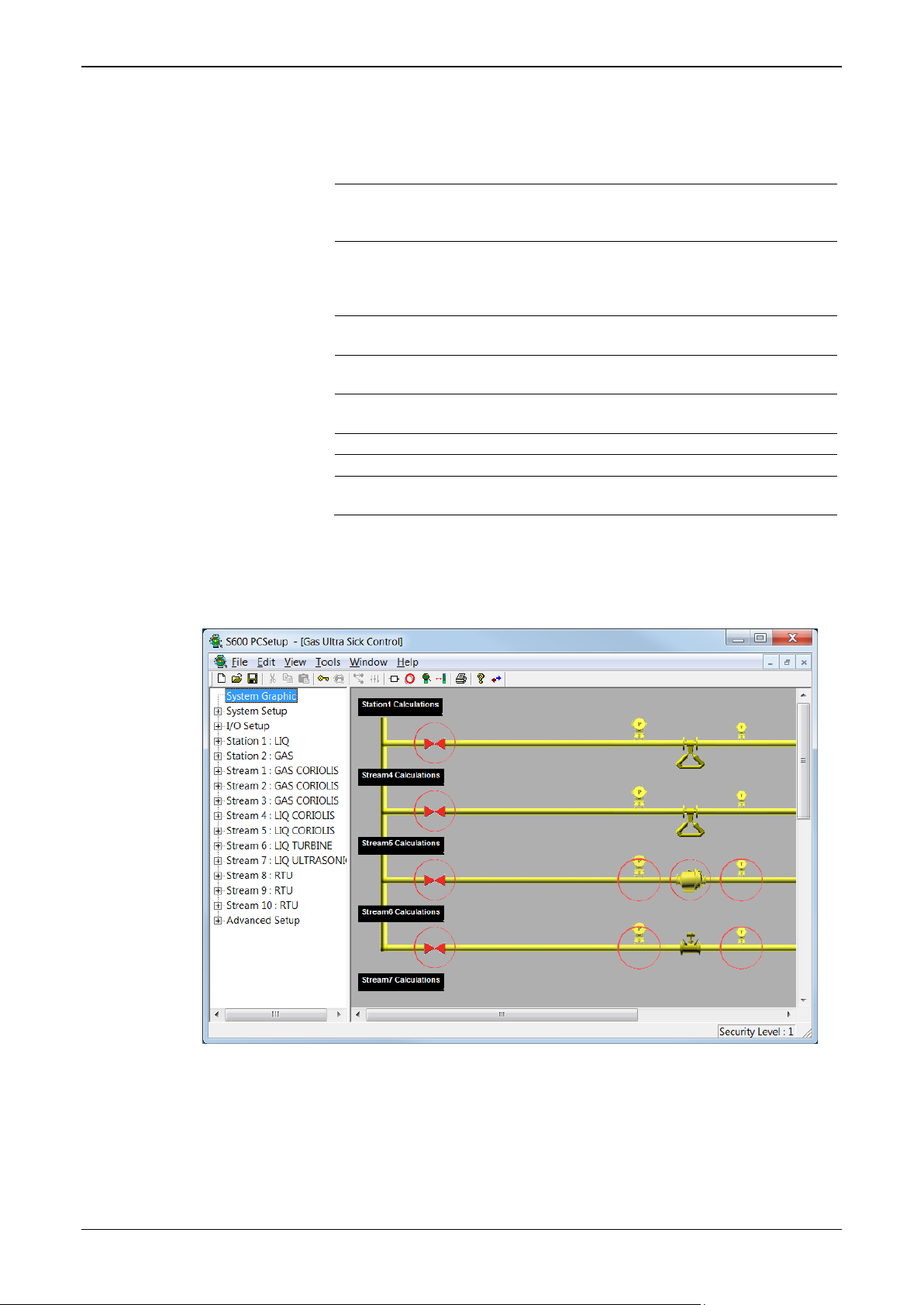
Config600 Configuration Software User Manual
Field
Description
Description
Displays the description you assigned to this
wizard.
Config Version
Indicates the number of times the configuration
you save a configuration.
Last Edited
Indicates the date the configuration was last
saved.
Config Format
Identifies the template version number used to
generate the configuration file.
Min Firmware
Identifies the minimum version of firmware that
supports the configuration file.
OK
Click to open the selected configuration file.
Cancel
Click to cancel the action and close this window.
Delete
Click to delete this configuration from the Config
folder.
2. Click the name of a configuration file in the left-hand pane. Note
that the OK and Delete buttons in the right-hand pane become
active, and the software completes the following fields:
configuration in Step 1 of the configuration
file has been edited and saved since its creation.
The system increments this number only when
3. Click OK. The system opens a configuration-specific S600
PCSetup screen (note the change in the heading for the screen),
displaying a graphic representation of that configuration:
Refer to Section 2.2 for further information on using the System
Graphic.
2-24 PCSetup Editor Revised February 2022
Figure 2-24. Configuration-specific System Graphic
Page 51

Config600 Configuration Software User Manual
Configuration Screen
Hierarchy Menu
Note: By default, PCSetup logs you in at Security Level 1(as shown
in the lower right-hand corner of the screen). Level 1 has the
greatest access to software features and functions; level 9 has
the most restrictions. Refer to Security in Chapter 7, Advanced
Setup Configuration, for further information on defining
security levels.
2.3.1 Navigating the PCSetup Editor
The PCSetup Editor window consists of two panes: a hierarchy menu
in the left-hand pane and various configuration screens that appear in
the right-hand pane. Figure 2-25 shows a sample screen.
Revised February 2022 PCSetup Editor 2-25
Figure 2-25. PCSetup Editor
Located on the left-hand side of the screen, the hierarchy menu
displays the major configuration components: System Graphic, System
Setup, I/O Setup, Station(s), Stream(s), and Advanced Setup. Clicking
on an item in the hierarchy menu displays a sub-menu. Each submenu
has an associated configuration screen.
Refer to the following for information on each configuration
component:
System Graphic: Section 2.2 of Chapter 2
System Setup Configuration: Chapter 3.
I/O and Communications: Chapter 4.
Stations: Chapter 5.
Page 52

Config600 Configuration Software User Manual
Icon
Meaning
New Configuration. Click this icon to open the Config600
Note: This applies only to the Config600 Pro software.
Open Configuration. Click this icon to open the Select Config
dialog box.
Save Configuration. Click this icon to save the current
configuration with the current configuration file name.
Cut, Copy and Paste. These clipboard icons are available if not
insert the contents of the clipboard at the cursor’s location.
Login. Click this icon to open the Login dialog box.
Note: This applies only if Level 1 security has been enabled.
Edit Security. Click this icon to open the Edit Security dialog box.
Assignment. Click this icon to open the Edit Assignments dialog
box for the selected data point.
Settings. Click this icon to open the Edit Settings dialog box for
the selected data point.
Calc Explorer. Click this icon to open the Calc Explorer utility,
components.
Config Organiser. Click this icon to display a Config Organiser
configuration.
Displays. Click this icon to open the Display Editor (see
13, Display Editor).
Config Transfer. Click this icon to open the Config Transfer utility.
(see Chapter 9).
Print. Click this icon to open the Print dialog box. Use this icon to
print the relevant pane selection to a host printer.
About Config600. Click this icon to open the About Config600
dialog box that displays copyright and version information.
Streams: Chapter 6.
Advanced Setup: Chapter 7.
The configuration screens on the right-hand side of the screen contain
parameter fields, check boxes, and buttons. Fields allow you to type
characters and numbers or to select from drop-down lists. Check boxes
enable you to select specific options. Buttons link to dialog boxes that
allow you to configure a data point or parameter.
Located at the top of the PCSetup Editor screen, the menu bar and icon
bar have the customary Windows-based software options, plus
additional menu selections and icons specific to Config600.
2.3.2 The Icon Bar
The icon bar, located immediately below the menu bar at the top of the
screen, provides icons for the following actions or shortcuts:
Table 2-1. Config600 Icon Bar
Configuration Generation screen sequence.
greyed out. Click Cut to remove the selection from the clipboard.
Click Copy to store the selection to the clipboard. Click Paste to
and examine calculation relationships between system
and add, clone, delete, rename, or reorder components of a
2-26 PCSetup Editor Revised February 2022
Chapter
Page 53

Config600 Configuration Software User Manual
Menu
Meaning
File Menu
Close
Closes an open configuration file.
Save
Print Preview
Opens the selected configuration file in the print preview window.
Recent File
Opens or view recently edited configuration files.
Regenerates the selected configuration file to overwrites all
Reports
& Paste
Launches the Config Organiser to arrange the priority of
Restricts access to authorised system users and determines
Split
Startup Screen
Launches the initial Startup Screen.
Transfer
2.4 The Menu Bar
The menu bar, located immediately above the icon bar at the top of the
screen, provides the following actions or shortcuts:
Table 2-2. Config600 Menu Bar
Use these menu options to print, open, close, and save configuration files.
New Creates a new configuration file.
Open Opens an existing configuration file.
Save As Saves the selected configuration file with a different name.
Login
Print Prints the selected configuration file.
Print Setup
Regenerate
Exit Closes the PCSetup Editor.
Edit Menu
Config Organiser
Security
Assignment
Settings Opens the Edit Settings dialog box for the selected data point.
View Menu
Tool Bar Views or hides the Tool Bar.
Status Bar Views or hides the Status Bar.
Use these menu options to open the Config Organiser, Assignment, and Settings
screens.
Undo, Cut, Copy,
Use these menu options to view the Tool bar, Status bar, change the frame sizes, and
open the Startup Screen.
Saves the selected configuration file.
Login to the PCSetup Editor
Opens the Windows Print Setup window to configure your default
printer.
modifications to displays and Modbus maps with the standard
displays and Modbus maps as generated at the build time of the
configuration.
Note: To regenerate a report, delete the report and add the
report using PCSetup Editor > System Setup >
.
These functions are disabled in the PCSetup Editor.
configurations so a certain I/O is read before another, rename or
clone I/O modules, streams or stations, and delete I/O modules.
which data items system users can enter or modify.
Opens the Edit Assignments dialog box for the selected data
point.
Changes the frame sizes.
.
Tools Menu Use this menu to open the Display Editor or the Config Transfer utility.
Edit Displays Opens the Display Editor.
Revised February 2022 PCSetup Editor 2-27
Opens the Config Transfer utility.
Page 54

Config600 Configuration Software User Manual
arrange icons, and view or select open configurations.
New Window
Opens a second instance of the configuration file in a new
Configurations
Contents
information about the software (including the version number).
Menu Meaning
Windows Menu
Cascade
Tile
Arrange Icons
Use these menu options to configure how your screens display, clone a configuration,
window to view a different screen.
Displays all open configuration windows in a Cascade view.
Displays all open configuration windows in a Tile view.
Arranges icons according to a grid pattern.
Open
Opens active configurations.
Help Menu
About PCSetup
Use these menu options to access the online help system and view the About PCSetup
information screen.
Accesses the online help system.
Displays the About PCSetup dialog box, which contains
2.5 Managing Configurations
This section discusses how to save and regenerate a configuration.
2.5.1 Save a Configuration
To avoid losing any work as you develop your configuration, it is a
good practice to save the configuration file after you make any
changes.
Config600 creates a separate folder in your computer’s Config600
folder for each unique configuration. At your request, Config600 saves
the configuration files in your computer’s Configs folder using the file
extension “.cfg” for the master configuration file. Other components
have individual sub-folders:
Reports: Contains the report format files.
Modbus: Contains the Modbus configuration files.
Logicalcs: Contains the custom written files that allow user-
defined functions.
Extras: Stores user-defined look-up tables and configuration
backup files.
To save the configuration file, select File > Save or File > Save As
while in any screen in the PCSetup Editor. To save the configuration
file with a new name, select File > Save As and then select “<new>”
from the list of file names.
2.5.2 Regenerate a Configuration
In the PCSetup Editor, you can edit displays, reports, or Modbus maps
using the Display, Report, or Modbus editors. Use the PCSetup Editor
to edit assignments, values, and modes of data points. Config600 saves
any file modifications in the Config folder and overwrites any previous
modifications.
2-28 PCSetup Editor Revised February 2022
Page 55

Caution
Regenerating a configuration file results in the loss of any custom
displays or Modbus maps.
2.6 Display Editor
ALWAYS create a backup of your configuration file before using the
any LogiCalcs, displays, reports, or Modbus maps.
Config600 Configuration Software User Manual
Note: To regenerate reports, delete the report and add the report using
PCSetup Editor > System Setup > Reports.
The File > Regenerate command overwrites all modifications to
displays and Modbus maps with the standard displays and Modbus
maps as generated at the build time of the configuration. Modifications
to the settings and assignments in the configuration file (extension
.cfg) are reflected in the regenerated files.
Use the Regenerate command to force configuration setting
modifications to the displays and Modbus maps.
Click the Edit Displays icon on the PCSetup tool bar to open the
Display Editor. Use it to customize the appearance of displays on the
front panel of the S600+. Refer to Chapter 13, Display Editor, for
complete instructions on using this utility.
Note: You can also access this utility either by selecting Tools >
Display Editor from the PCSetup menu bar or by selecting
Start > Config600 3.3 > Display Editor.
2.7 Config Transfer Utility
Click the Config Transfer icon on the PCSetup tool bar to open the
Config Transfer utility. Use it to send new or modified configuration
files to the S600+ using either a dedicated serial port or a TCP/IP
connection. Config Transfer also enables you to retrieve configuration
files from the host PC to the S600+. Refer to Chapter 9, Config
Transfer, for complete instructions on using this utility.
Note: You can also access this utility either by selecting Tools >
Transfer from the PCSetup menu bar or by selecting Start >
Config600 3.3 > Config Transfer.
2.8 Config Organiser Utility
Use the Config Organiser to arrange the priority of configurations so a
certain I/O is read before another, rename or clone I/O modules,
streams or stations, and delete I/O modules.
Caution
Config Organiser. The Config Organiser does not automatically update
1. To open the Config Organiser, either:
Click the Config Organiser icon on the PCSetup Editor’s tool
bar.
Revised February 2022 PCSetup Editor 2-29
Page 56

Config600 Configuration Software User Manual
Button
Description
Move Up
Selects an I/O module and moves it to a
certain I/O is read before another.
Move Down
Selects an I/O module and moves it to a
certain I/O is read before another.
Clone
Duplicates an I/O module, stream, or station
file within the configuration.
Rename
Renames an I/O module, stream, or station
to rename that file within the configuration.
Delete
Deletes an I/O module from the
configuration.
OK
Applies the indicated changes to the
your changes.
Cancel
Cancels the action and closes this window.
Select Edit > Config Organiser from the PCSetup Editor’s
menu bar.
The Config Organiser screen displays:
Figure 2-26. Config Organiser
2. Click a button to manage the displayed configuration files
higher priority in the configuration so a
lower priority in the configuration so a
configuration file.
Note: Config600 displays a verification dialog
box. You must answer Yes to finalise
2-30 PCSetup Editor Revised February 2022
Page 57

Chapter 3 – System Setup
Hierarchy
Menu
System
Setup
Hierarchy
Pane
In This Chapter
3.1 Versions .............................................................................................. 3-2
3.2 Units ................................................................................................... 3-3
3.2.1 Supported Units ........................................................................ 3-4
3.3 Reports ............................................................................................... 3-6
3.3.1 General Reports ....................................................................... 3-7
3.3.2 Base Time Reports ................................................................... 3-8
3.3.3 Default Reports ......................................................................... 3-9
3.3.4 Report History........................................................................... 3-9
3.3.5 Adding a General Report to a Configuration ............................. 3-9
3.3.6 User Reports .......................................................................... 3-11
3.3.7 Adding a Base Time Report to a Configuration ...................... 3-11
3.3.8 Managing Configuration Reports ............................................ 3-13
3.4 Totalisations ..................................................................................... 3-14
3.5 Time .................................................................................................. 3-16
System Setup is the second option in the hierarchy pane on the S600
PCSetup screen. System settings include company details, units of
measurement, required reports, and totals. While you define these
during the initial configuration process, you can use the System Setup
option to edit these values when necessary.
Config600 Configuration Software User Manual
Figure 3-1. System Setup screen
When you double-click System Setup, the hierarchy opens to display
the sub-options: Versions, Units, Reports, Totalisations, and Time.
Revised February 2022 System Setup 3-1
Page 58

Config600 Configuration Software User Manual
Config Format 8
As shown in Figure 3-2, Version 3.3 of Config600 uses Config
Field
Description
Machine Name
Provides a tag number or stream name, up to four
“S600”) on all printed alarms and events.
Company Name
Provides a short description (up to ten alphanumeric
characters) for the company.
Address 1 through
Provides up to five 30-alphanumeric character fields
Telephone
Provides up to 30 alphanumeric characters for your
company’s telephone number.
Fax
Provides up to 30 alphanumeric characters for your
company’s fax number.
Config Version
This read-only field shows the number of times this
configuration has been saved since it was created.
3.1 Versions
Versions include details of your company and the flow computer being
used. Config600 uses this information in webserver access windows.
Format 8 for its configuration files. Config Format 8 is designed to
work with Release 5.0 of the CPU module (P152).
Note: Older configuration files (for release 4.0 or earlier of the CPU
module) use Config Format 7. We cannot guarantee that
configurations you create using Config Format 8 will work
with older releases (4.0 or earlier) of the CPU module.
Figure 3-2. Versions screen
When you click Versions, Config600 displays a configuration screen
in the right-hand pane. Unless otherwise indicated, you can edit the
following fields:
characters in length. Config600 uses this tag (such as
Address 5
you use to enter your company’s address.
3-2 System Setup Revised February 2022
Page 59

Config600 Configuration Software User Manual
Field
Description
Config Created
This read-only field shows the date and time the
configuration was originally created.
Config Last Edited
This read-only field displays the date and time the
configuration was last saved.
Config Format
This read-only field shows the version number of the
older CPUs.
template used to create the configuration.
Note: Configuration templates are based on the CPU
version. Earlier versions (4 or prior) of the CPU
module use configuration templates version 7 or
earlier; the version 5 CPU module uses the
version 8 configuration template. Configurations
based on earlier templates function with the new
CPU module. However, configurations
developed for the new CPU do not work with
Note: If you change any values on this screen and try to exit,
Config600 displays a dialog box asking to save those changes
to your configuration file.
3.2 Units
Click Yes to apply the changes to your configuration file.
Using the Units options, you define the default standard units of
measurement used throughout the configuration. Config600 performs
all calculations using units, which conform to the appropriate
international standards. However, should the requirements of your
application vary, you can change the displayed units of measurement.
When you change unit values, the PCSetup Editor automatically
performs unit conversions.
You can also override a number of units (such as K-factor) at the
stream level.
Note: Click Conversions/Constants to switch between the Units
screen and the Conversions/Constants option in Advanced
Setup.
Revised February 2022 System Setup 3-3
Page 60

Config600 Configuration Software User Manual
Figure 3-3. Units screen
Each process quantity has a predefined list of selectable units. Click
to select the units preferred for your application. Config600 removes
any units not used in this configuration.
Note: If you change any values on this screen and try to exit,
Config600 displays a dialog box asking to save those changes
to your configuration file.
Click Yes to apply the changes to your configuration file.
3.2.1 Supported Units
3-4 System Setup Revised February 2022
Page 61

Config600 Configuration Software User Manual
Unit Category
Supported Units
Mass
kg, lbs, M.lbs, MM.lbs, tonne, UK.ton, US.ton
Mass Flow Rate
kg/d, kg/h, kg/m, kg/s, lbs/d, lbs/h, M.lbs/d,
UK.t/h, US.t/d, US.t/h
Uncorrected Vol
bbl, CF, kL, km3, L, m3, MCF, MMCF, US
gal
Uncorrected Vol Flow Rate
bbl/d, bbl/h, CF/d, CF/h, kL/d, kL/h, km3/d,
US.gal/h
Corrected Vol
MMSCF, MSCF, Sbbl, SCF, SkL, Skm3, SL,
Sm3, US.Sgal
Corrected Vol Flow Rate
MMSCF/d, MMSCF/h, MSCF/d, MSCF/h,
Sm3/h, US.Sgal/d, US.Sgal/hr
Energy
Btu, Gcal, GJ, Kkcal, KJ, kW.h, mcal, MJ,
MMBtu, MMMBtu, TJ
Energy Flow Rate
Btu/h, Gcal/d, Gcal/h, GJ/d, GJ/h, Kcal/d,
MMBtu/h, MMMBtu/d, MMMBtu/h, TJ/d, TJ/h
Liquid Alternative Vol
MMSCF, MSCF, Sbbl, SCF, SkL, Skm3, SL,
standard.
Liquid Alternative Mass
kg, lbs, M.lbs, MM.lbs, tonne, UK.ton, US.ton
Note: Only used in batching configurations.
TEMP UNITS
(Temperature)
Deg.C, Deg.F, K
PRESS UNITS
bara, barg, kgf/cm2a, kgf/cm2g, kPa.a,
psig
DP UNITS
(Differential Pressure)
barg, inH2O, Kg/cm2, kPa, mbar, Mpa, psig
DENS UNITS
(Density)
API, gm/cc, kg/L, kg.m3, kg/Sm3, lbs/bbl,
lbs/CF, SG
ROC TEMP UNITS
Temperature)
Deg.C/s, Deg.F/s, Deg.K/s
ROC PRESSURE UNITS
(Rate of Change, Pressure)
bar/s, kPa/s, psi/s
CV VOL Units
(Calorific Value)
kW.h/m3, MJ/kg, MJ/Sm3
DYN VISC UNITS
(Dynamic Viscosity)
cP, lbm/ft.s, mPa.s, Pa.s, uPa.s
Table 3-1 lists the standard units of measurement Config600 supports.
Table 3-1. Standard Measurement Units
M.lbs/h, MM.lbs/d, MM.lbs/h, t/d, t/h, UK.t/d,
km3/h, L/d, L/h, L/m, m3/d, m3/h, MCF/d,
MCF/h, MMCF/d, MMCF/h, US.gal/d,
Sbbl/d, Sbbl/h, SCF/d, SCF/h, SkL/d, SkL/h,
Skm3/d, Skm3/h, SL/d, SL/h, SL/m, Sm3/d,
(Pressure)
Kcal/h, KJ/d, KJ/h, kW.h/d, kW.h/h, MBTu/d,
Mcal/d, Mcal/h, MJ/d, MJ/h, MMBtu/d,
Sm3, US.Sgal
Notes:
Only used in batching configurations.
The conversion between units also
compensates for the difference in metric
and imperial ‘standard’ conditions (i.e.
m3 @ 15’C / 0 barg is converted to bbl
@ 60F / 0 psig) as per the Aramco
kPa.g, mmH2O, mmHg, Mpaa, MPag, psia,
Revised February 2022 System Setup 3-5
(Rate of Change,
BTU/lb, BTU/SCF, GJ/kg, GJ/Sm3, kcal/m3,
Page 62

Config600 Configuration Software User Manual
Unit Category
Supported Units
DIAM UNITS
(Diameter)
cm, ft, in, m, mm, yd
LENGTH UNITS
cm, ft, in, m, mm, yd
VEL UNITS
(Velocity)
ft/s , m/s
K factor
pls/bbl, pls/CF, pls/kg, pls/L, pls/lbs,
pls/US.gal, pls/US.ton
Field
Description
General Reports
Displays the general reports available for selection.
Add
Click to add a new report.
Configure
Click to configure the selected report.
Edit
Click to edit the selected report using the
Report Editor.
Delete
Click to delete the selected report.
Maintenance Mode
Enables the system to access turbine mode, DP mode,
does not select this option for metric configurations.
Time Editor
Click to display the System Setup > Time screen you
selected report.
Totals
Click to display the the Advanced Setup > Total
for the selected report.
Base Time
Click ▲ or ▼ to select the base time for which you
3.3 Reports
Click the Reports option to display a screen identifying the reports
currently associated with your configuration (Figure 3-4). Config600
provides two report categories, General and Base Time.
pls/M.lbs, pls/MM.lbs, pls/m3, pls/tonne,
Interlock
Descriptions
3-6 System Setup Revised February 2022
Figure 3-4. Reports screen
and densitometer information regardless of the
Maintenance Mode status. By default, Config600
selects this option for imperial-based configurations but
use to configure time and data parameters for the
Descriptions screen you use to configure descriptions
Page 63

Field
Description
want to add a report.
abiltity to generate EFM reports.
Hours after
midnight
Sets the beginning hour for the specified base time. 6
is the default hour.
Multi-day periods
Selects how many days a report should cover. Click ▼
2.
Part hour period
Indicates how many minutes apart you want reports to
Time 2.
Report Periods
Displays the current report periods associated with the
report you select in the General Reports pane.
Add
Click to add a new report period.
Configure
Click to configure the selected report
you select a report period.
Edit
Click to edit the report period you
you select a report period.
Delete
Click to configure the selected report.
you select a report period.
Start of
Indicates when the report period starts.
Week
Indicates the weekday on which the
valid values. The default is Sunday.
Month
Indicates the day of the month on which
First Day.
Report Name
Definition
Batch
Shows totals at the start and end of the batch.
Config600 Configuration Software User Manual
Note: Although you can define three sets of base time
reports, Config600 reserves the Hourly and
Dailyl reports in base time 2 for Electronic Flow
Management (EFM) reports (if an EFM Modbus
module link is included in the software). You can
overwrite these values, but it may eliminate your
to display valid values. 1 is the default.
Note: Once you set this value, the system uses this
as a fixed period across all three Base Times.
For example, you cannot then change a period
of 10 days to a period of 5 days for Base Time
generate. Click ▼ to display valid values. 1 is the
default.
Note: Once you set this value, the system uses this
as a fixed period across all three Base Times.
For examle, you cannot then change a period
of 10 minutes to a period of 5 minutes for Base
3.3.1 General Reports
General reports, which generate as a result of some exception event,
include:
period.
Note: This button does not display until
selected in the Reports Editor.
Note: This button does not display until
Note: This button does not display until
report period starts. Click ▼ to display
the report period starts. Valid values are
Last Day and First Day. The default is
Revised February 2022 System Setup 3-7
Page 64

Config600 Configuration Software User Manual
Current
panel or webserver.
Maint
Shows totals as you enter and exit maintenance mode.
STN01 Prv Vol
Vol
Reserved for prover configurations; summarises trial
STN01 Prv Mass
Mass
Reserved for prover configurations; summarises trial
CHR D/Load
Generates when the chromatograph download data
changes or when a timeout or mode change occurs.
CHR Telemetry
Generates on the receipt of a new analysis from the
chromatograph.
Batch Ticket
Shows totals and batch details at the start and end of
Note: This report replaces the Batch report.
User-defined
15 reports with content you define.
Time
Definition
Hourly
Shows throughput for the previous hour.
2 Hourly
Shows throughput for the previous two hours.
3 Hourly
Shows throughput for the previous three hours.
4 Hourly
Shows throughput for the previous four hours.
6 Hourly
Shows throughput for the previous six hours.
8 Hourly
Shows throughput for the previous eight hours.
12 Hourly
Shows throughput for the previous twelve hours.
Daily
Shows throughput for the previous day.
Weekly
Shows throughput for the previous week.
Monthly
Shows throughput for the previous month.
Batch Hourly
Shows, for each hour during a batch, the batch hourly
batch.
Multi Day
Shows throughput for the previous multi-day period, as
2.
Shows the current flow rate and cumulative totals.
Note: You can request this report from the S600+ front
and STN02 Prv
and STN02 Prv
runs and final volume data for a prove run.
runs and final mass data for a prove run.
the batch. It also generates if a batch recalculation
occurs.
Note: If you import older configuration files into Config600, the
Compact Hourly report option may appear on this listing. This
report, a system-generated base time Hourly report, is available
but no longer supported.
3.3.2 Base Time Reports
Base time reports provide system data as of a particular hour (base
time) you define. Base time reports include:
total and the batch total.
Note: Config600 generates this report only during
batches. If a batch finishes midway through an
hour, Config600 does not generate the batch
hourly value for that hour but does generate the
end-of-batch value that contains totals for that
defined in the Multi-day period field.
Note: Once you set this value, the system uses this
as a fixed period across all three Base Times.
For example, you cannot then change a period
of 10 days to a period of 5 days for Base Time
3-8 System Setup Revised February 2022
Page 65

Config600 Configuration Software User Manual
Time
Definition
Part Hour
Shows throughput for previous part-hour period, as
Time 2.
defined in the Part hour period field.
Note: Once you set this value, the system uses this
as a fixed period across all three Base Times.
For examle, you cannot then change a period
of 10 minutes to a period of 5 minutes for Base
Note: Although Config600 provides up to three base time categories
for reports, Config600 reserves base time 2 for Electronic Flow
Measurement (EFM) reports, which typically do not print.
Refer to Chapter 14, Modbus Editor, for further information.
3.3.3 Default Reports
Config600 provides five default reports:
General Reports: Current (set to print and store five instances).
Base Time 1 Reports:
• Hourly (set to print and store 24 instances of this report).
• Daily (set to print and store 35 instances of this report).
Base Time 2 Reports (reserved for EFM reports):
• Hourly (set to store 840 instances of this report).
• Daily (set to store 35 instances of this report).
3.3.4 Report History
The S600+ saves all periodic reports in circular buffers. For example,
you decide to save five instances of that report. After saving those five
reports and generating reports 6 and 7, the S600+ then overwrites the
data for reports 1 and 2. How many reports you can save is a function
of the available memory on the S600+. Refer to Section 3.3.5, Adding
a General Report to a Configuration for information on the total
number of reports you can save.
Note: If necessary, you can use the Report Editor to change the report
format. Any data existing in Config600 is available for
inclusion on a report, and you can change a report’s format at
any time.
3.3.5 Adding a General Report to a Configuration
Note: Refer to Appendix H, CFX Reporting, for more information on
Use this procedure to add a General report to your configuration file.
1. Click Add in the General Reports pane. The Archive Configuration
Revised February 2022 System Setup 3-9
CFX reports.
dialog box displays:
Page 66

Config600 Configuration Software User Manual
Field
Description
Archive
Indicates the General reports available for selection. Click
name from this listing.
Number of
Indicates the number of instances of this report to save.
iteration of the generated report with the sixth.
Print when
Generated
Indicates whether Config600 prints the report after
generating it.
Web history
Indicates whether the selected report appears as an option
in the Reports display on the S600+ Webserver.
Report
Exports the report formatted as either a text file or a CSV
file to a location you specify.
Web
summary
Indicates whether Config600 includes report data “live” as
part of the webserver menu bar.
Preformatted
Indicates whether Config600 uses its native HTML
Support for further information.
Figure 3-5. Archive Configuration dialog box
2. Complete the following values:
Period
reports to
save
to display the reports for selection.
Note: When you select a report from this list and add it to
the configuration file, Config600 removes that report
Click or to increase or decrease the displayed value.
Note: The total number of reports you can save is a
function of the available storage on the S600+ after
you create a configuration file and cold start it.
Config600 also uses a “report buffer” to store
reports. If you select 5, Config600 overwrites the first
Export
HTML
3-10 System Setup Revised February 2022
formatting when displaying webserver-based reports or
uses your HTML formatting. Select this option to use your
HTML formatting for reports.
Note: This is an advanced option. Contact Techical
Page 67

Config600 Configuration Software User Manual
3. Click OK when you are finished. The Archive Configuration
dialog box closes. Config600 adds your report to the General
Reports listing.
3.3.6 User Reports
S600+ also provides 22 user-defined reports (USER18 through
USER24) in the General Reports category. Use these reports when you
have developed special programs (such as a LogiCalc) to trigger report
conditions or desire to use them on the webserver. You can also use
these reports to add your own displays on the Webserver menu bar.
Note: The disable form feed function is not available with user
reports.
3.3.7 Adding a Base Time Report to a Configuration
Use this procedure to add a base time report to your configuration file.
1. Click or in the Base Time Reports pane of the Report screen
to select the base time for which you want to add a report.
Note: Although you can define three sets of base time reports,
Config600 reserves the Hourly and Daily reports in base
time 2 for Electronic Flow Management (EFM) reports (if
an EFM Modbus module link is included in the software).
You can overwrite these values, but it may eliminate your
ability to generate EFM reports.
2. Complete the hours after midnight field to indicate the beginning
hour for the selected base time.
Revised February 2022 System Setup 3-11
Page 68

Config600 Configuration Software User Manual
Field
Description
Archive
Displays the base time reports available for selection. Click
name from this listing.
Number of
Indicates the number of instances of this report to save.
with the sixth.
Print when
Generated
Indicates whether Config600 prints the report after
generating it.
Web history
Indicates whether the selected report appears as an option
in the Reports display on the Config600 webserver.
Report
Export
Exports the report formatted as either a text file or a CSV
file to a location you specify.
Web
summary
Indicates whether Config600 includes report data “live” as
part of the webserver menu bar.
Preformatted
Indicates whether Config600 uses its native HTML
Support for further information.
3. Click Add in the General Reports pane. The Archive Configuration
dialog box displays:
Figure 3-6. Archive Configuration
4. Complete the following values:
Period
reports to
save
to display the reports you can select.
Note: When you select a report from this list and add it to
the configuration file, Config600 removes that report
Note: The total number of reports you can save is a
function of the available storage on the S600.
Config600 also uses a “report buffer” to store
reports. For example, if you select 5, Config600
overwrites the first iteration of the generated report
HTML
3-12 System Setup Revised February 2022
formatting when displaying webserver-based reports or
your HTML formatting. Select this box to use your HTML
formatting for reports.
Note: This is an advanced option. Contact Techical
Page 69

Config600 Configuration Software User Manual
Field
Description
CFX Stream
Indicates whether Config600 generates a CFX report for
Appendix H, CFX Reporting.
Report
Field
Daily
Indicates the beginning day of the week. Click or to
select a day. The default is Sunday.
Monthly
Indicates whether the month “starts” on the last day of the
value. The default is First Day.
X
this stream. For more information on CFX reports, refer to
5. Click OK when you finish. The Archive Configuration dialog box
closes. Config600 adds your report to the Base Time Reports
listing.
6. Complete the following fields if you added these reports:
current month (Last Day or March 31) or the first day of the
next month (First Day or April 1). Click or to select a
3.3.8 Managing Configuration Reports
At any time you can manage—edit, delete, or reconfigure—the reports
you have added to your configuration file. Click on a report and
Config600 displays three additional buttons.
Click Configure to display the Archive Configuration dialog box.
Click Edit to access the Report Editor (Chapter 10).
Click Delete to remove the defined report from the configuration
file.
Figure 3-7. Managing Configurations
Note: If you change any values on this screen and try to exit,
Config600 displays a dialog box asking to save those changes
to your configuration file.
Revised February 2022 System Setup 3-13
Page 70
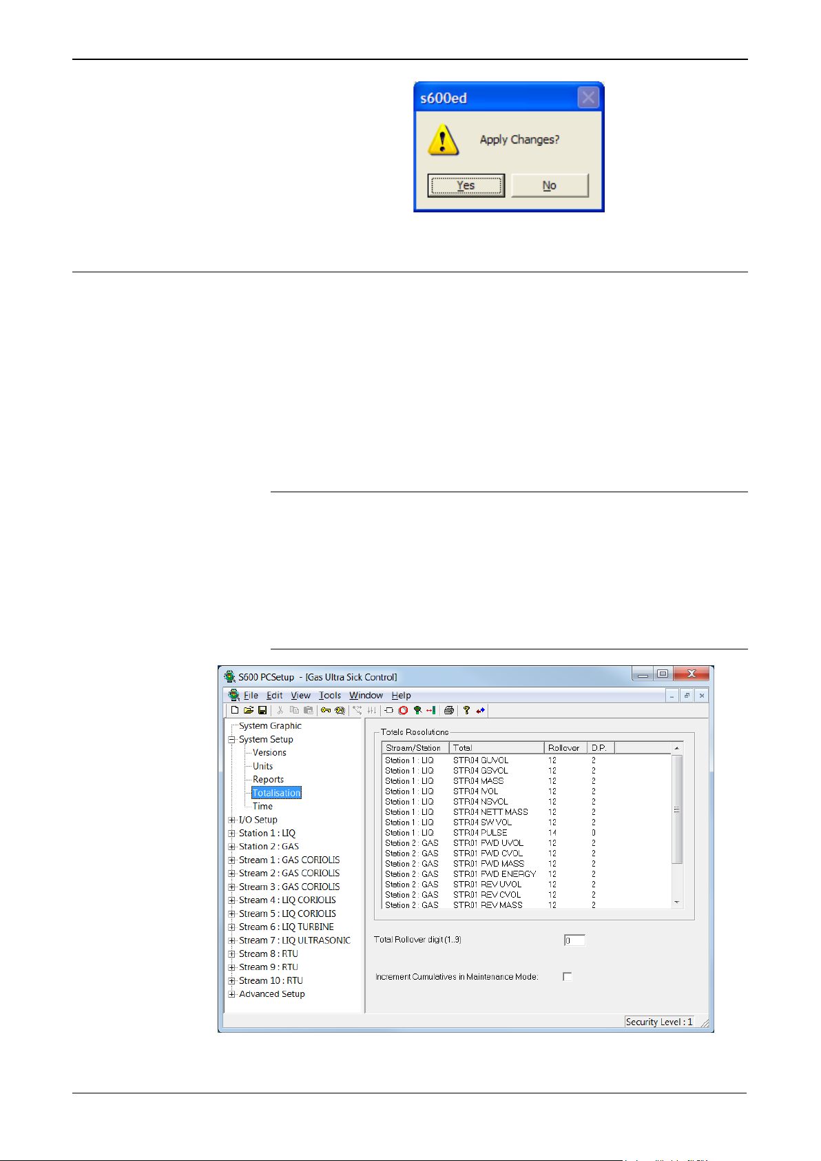
Config600 Configuration Software User Manual
Click Yes to apply the changes to your configuration file.
3.4 Totalisations
Click the Totalisation option on the hierarchy to display the
Totalisation screen (Figure 3-8). Use this screen to manage how the
system displays totals.
The Totalisation screen has three components: a Totals Resolutions
pane, a Total Rollover Digit field, and an Increment Cumulatives in
Maintenance Mode check box. Edit the Totals Resolution values using
a dialog (Figure 3-9). For example, if you set the Rollover value to 7
and the Decimal Place value to 3, rollover occurs at 9,999,999.999.
Similarly, if you set Rollover to 4 and Decimal Place to 2, rollover
occurs at 9,999.99.
Notes:
The main calculation routines always use full double-precision
accuracy for all totalisers and maintain accuracy internally, even if
you select a restricted number of decimal places for display and
reporting.
Base Sediment and Water volumes use Standard Volume Units.
This is true even when they are computed as gross volumes.
Figure 3-8. Totalisation
3-14 System Setup Revised February 2022
Page 71

Config600 Configuration Software User Manual
Field
Description
Largest Total
This read-only field shows the total’s current format. The
Note: No total can have more than 15 digits.
Rollover
Indicates the maximum number of digits in the total before
digits.
Decimal
Indicates the number of decimal places in the total. Valid
or decrease the total number of decimal places.
To edit totals:
1. Double-click a Station/Stream line in the Totals Resolution pane.
The Totals Detail dialog displays:
Figure 3-9. Totals Detail dialog
2. Complete the following values:
system changes this display as you modify the Rollover
and Decimal Places values.
it rolls over to zero. Valid values are 3 to 15. The default is
12. Click or to increase or decrease the total number
of digits.
Note: Set this value to ensure that when a stream flows at
its maximum possible flow rate, this limit would not
cause the total to roll over to zero within a 24-hour
period. Typically, leave the value at its default of 12
Places
values are 0 to 5. The default is 2. Click or to increase
3. Complete the Total Rollover digit field (see Figure 3-8) to
indicate the value at which rollover occurs. For example, if you
either leave this field at 0 (default) or set it to 9, rollover occurs at
9,999. If you set this field to 3, rollover occurs at 3,999, and so on.
4. Select the Increment Cumulatives in Maintenance Mode check
box (see Figure 3-8. Totalisation) to enable the S600+ to increment
all totals in maintenance mode. Otherwise the S600+ increments
only Maintenance Mode totals when in maintenance mode.
Note: If you change any values on this screen and try to exit,
Config600 displays a dialog asking to save those changes to
your configuration file.
Revised February 2022 System Setup 3-15
Page 72

Config600 Configuration Software User Manual
Click Yes to apply the changes to your configuration file.
3.5 Time
Click the Time option on the hierarchy to display the Date/Time
Parameters screen (Figure 3-10) and to manage how the system
formats dates and displays time. The FloBoss S600+ provides two
methods for time synchronisation: via NTP (refer to section 4.10
Communications Port) and via a supervisory system.
Figure 3-10. Date/Time Parameters
1. Review the Date Format, which S600+ uses when displaying
dates throughout the system. Click to display available format
options. The default format is DD MM YYYY.
2. Review the Time Accept value, which S600+ uses to perform time
synchronisation procedures for a supervisory system. Valid values
are:
3-16 System Setup Revised February 2022
Page 73

Config600 Configuration Software User Manual
Disabled
No time synchronisation is performed via the supervisory
computer. The default is Disabled.
Automatic
Time synchronisation is automatically performed whenever
there is a change in the time or date downloaded from the
supervisory computer. This requires the configuration of the
SYSTEM KPINTARR TIME AND DATE (DLOAD fields) in
the supervisory Modbus Map. When a change is seen in any of
these fields (DLOAD YEAR, DLOAD MONTH, DLOAD
DAY, DLOAD HOUR, DLOAD MINUTE, DLOAD
SECOND), the FloBoss S600+ immediately sets its internal
clock to these values.
It is also possible to configure the FloBoss S600+ to
synchronize the time when requested to do so by the
supervisory computer. This method allows the supervisory
computer to download the new time / date before it is needed
(at least 30 seconds in advance) and the synchronization is then
triggered when required. This triggering is done by using the
SYSTEM KPINT DLOAD TIME ACCEPT parameter. When
this field is set to 1 the FloBoss S600+ immediately sets its
internal clock to the values previously defined in the DLOAD
YEAR, DLOAD MONTH, DLOAD DAY, DLOAD HOUR,
DLOAD MINUTE, DLOAD SECOND fields.
To compensate for any delays in the communications link, a
DLOAD OFFSET value is provided (in seconds). If this is nonzero then the value is added to the required time (For example
if the DLOAD SECOND is set to 30 and the DLOAD OFFSET
is set to 10, then the FloBoss S600+ will set its seconds value
to 40).
More information on time synchronisation via Modbus can be
located in document ‟How To 61” (which can be obtained by
contacting Technical Support).
3. Select the Event Time Change option to raise an event whenever
you change the system time using Modbus.
4. Enter the Zone Hours and Zone Minutes in the Time Zone Offset
pane to set the local time. Local time in each time zone is GMT
plus the curent time zone offset (hours/minutes) for the location.
Revised February 2022 System Setup 3-17
Page 74

Config600 Configuration Software User Manual
Note: If time synchronization is being performed by a public NTP
server, then the Zone Hours / Zone Minutes fields need to
be updated to reflect the time difference from UTC. This
ensures the flow computer time is correct for its location.
(Public NTP servers send their time as UTC and the
configured Zone Hours / Zone Minutes are added or
subtracted).
5. Click in the DST Mode field to select the type of Daylight
Savings Time to use. Valid values are:
Disabled
Uses Daylight Savings Time as set on your computer
User
Selects whether the date changes through the years. You
configure the DST dates in the System Editor. Contact
Technical Support for advice on how to configure the User
DST Mode.)
Europe
Calcuates DST as outlined in COM(2000)302 final,
2000/0140(COD), “Directive of the European Parliament and
of the Council on Summer Time Arrangements”
• For the purposes of this Directive “summer time period”
shall mean the period of the year during which clocks are
put forward by 60 minutes compared with the rest of the
year.
• From 2002 onwards, the summer time period shall begin, in
every Member State, at 1:00 a.m., Greenwich Mean Time,
on the last Sunday in March.
• From 2002 onwards, the summer time period shall end, in
every Member State, at 1:00 a.m., Greenwich Mean Time,
on the last Sunday in October.
6. It is possible to provide a Daylight Saving Time status flag which
indicates Winter Time (value = 0) or Summer Time (value = 1).
This is only possible by use of the System Editor. Please contact
Technical support for a ‘How To’ document if this feature is
required.
Note: System Editor is available only with the Config600 Pro
software.
7. Click Yes to apply the changes to your configuration file.
3-18 System Setup Revised February 2022
Page 75

Config600 Configuration Software User Manual
Chapter 4 – I/O and Comms Configuration
In This Chapter
UU4.1UU UUDiscrete (Digital) Inputs (DI)UU .............................................................. 4-2
UU4.1.1UU UUAssigning Discrete (Digital) OutputsUU ..................................... 4-2
UU4.1.2UU UUEditing Discrete (Digital) OutputsUU.......................................... 4-3
UU4.1.3UU UUAdding Discrete (Digital) OutputsUU ......................................... 4-4
UU4.2UU UUDiscrete (Digital) Outputs (DO)UU.......................................................... 4-5
UU4.2.1 Assigning Discrete (Digital) Outputs ..................................... 4-5
UU4.3UU UUAnalog Inputs (AI)UU .............................................................................. 4-6
UU4.3.1 Assigning Analog Inputs (AI) ................................................ 4-6
UU4.3.2 Editing Analog Inputs (AI) ..................................................... 4-7
UU4.3.3 Adding a New I/O Point ...................................................... 4-15
UU4.4 Analog Outputs (AO) ....................................................................... 4-15
UU4.4.1 Editing Analog Outputs ....................................................... 4-15
UU4.5UU UUDensity InputsUU.................................................................................. 4-17
UU4.5.1 Assigning Density Input ...................................................... 4-17
UU4.5.2 Editing Density Inputs ......................................................... 4-18
UU4.6UU UUTurbine InputsUU ................................................................................. 4-19
UU4.6.1 Assigning Turbine Inputs .................................................... 4-19
UU4.6.2 Editing Turbine Inputs ......................................................... 4-21
UU4.7UU UUPulse OutputsUU .................................................................................. 4-21
UU4.7.1 Assigning Pulse Outputs .................................................... 4-22
UU4.8UU UUHART ModulesUU ................................................................................ 4-22
UU4.8.1 Editing HART Settings ........................................................ 4-23
UU4.9UU UUPID Loop SettingsUU ........................................................................... 4-23
UU4.9.1 Assigning PID Loops .......................................................... 4-24
UU4.9.2 Proportional Plus Integral and Derivative Action ................ 4-28
UU4.10UU UUCommunications PortUU ...................................................................... 4-30
UU4.10.1 Editing a Communications Task ......................................... 4-30
UU4.10.2 Setting Up Peer-to-peer Options ........................................ 4-34
The configuration process assigns default I/O channels to all input and
output data items—including analog input and digital (discrete) input
signals, turbine inputs, Highway Addressable Remote Transducer
(HART®) transmitters, and communication tasks—the S600+ uses.
Using the I/O Setup option in PCSetup Editor, you can change an
assigned channel, unassign channels, and modify settings for your
configured channels. You can also modify the communication tasks,
including allocating communications links and defining serial port
settings. Refer to XXFigure 4-1XX for a sample screen. Note that some items
have already been assigned values.
Revised February 2022 I/O and Comms Configuration 4-1
Page 76
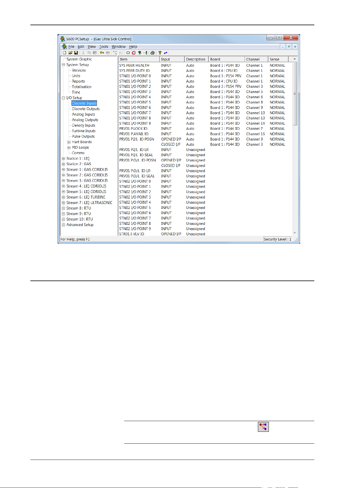
Config600 Configuration Software User Manual
Figure 4-1. Typical I/O Setup Screen (Discrete Inputs Shown)
4.1 Discrete (Digital) Inputs (DI)
You can assign each of the data items to a specific digital
input channel on an available I/O module. You can also configure
additional user-defined inputs for extra signals, if required.
Each I/O module (P144 I/O) you install provides up to 16 digital input
channels. Each Prover module (P154 PRV) you install provides up to
32 digital input channels. Each HART (P188) module you install
provides up to 12 digital input channels. Finally, the CPU module
(CPU I/O) provides a DIGIN channel.
4.1.1 Assigning Discrete (Digital) Inputs
To assign or reassign digital input data items:
1. Select Digital Inputs from the hierarchy menu.
2. Double-click the digital input you desire to edit. The Digital Input
Selection dialog box displays.
Note: You can also click the Assignment icon on the toolbar
to display the dialog box.
4-2 I/O and Comms Configuration Revised February 2022
Page 77

Config600 Configuration Software User Manual
3. Select the I/O Board to assign the digital input or select
Unassigned to deselect the input. Config600 completes the I/O
Channel field with available channels:
Figure 4-2. Digital Input Selection dialog box
4. Select an I/O Channel.
5. Select the Sense for the digital input bit. The default is Normal.
Invert reverses the signal’s state.
6. Click OK to apply the new assignment. The PCSetup screen
displays showing your new assignment.
Note: The PCSetup Editor displays a warning message if you
assign the I/O channel to more than one digital input. Use
caution: the PCSetup Editor displays a message but does
not prevent you from assigning the input more than once.
4.1.2 Editing Discrete (Digital) Inputs
To edit the description for a digital input data item:
1. Right-click the data item. The system displays a shortcut menu.
Note: You can also click the Settings icon on the toolbar after
highlighting the data item to display the menu. However, if
this option is not available for this item, the system greys
out this icon.
2. Select Settings on the menu. The Edit Descriptions dialog box
displays:
Revised February 2022 I/O and Comms Configuration 4-3
Page 78

Config600 Configuration Software User Manual
Figure 4-3. Edit Description dialog box
3. Edit the current description or enter a new description.
Note: The S600+ does not pass this value to the Config600
configuration or display. Use this process only to customize
or clarify the value on this screen.
4. Click OK to confirm the change. The PCSetup screen displays
showing the edited label.
4.1.3 Adding Discrete (Digital) Inputs
To add an additional data item:
Note: When you add a digital I/O point, the point is an object that is
capable of using 16 digital inputs to derive its value. This
means that a single object can have a value between 0 and
65535 as its decimal equivalent. This value shows as 16 bits in
the Digital Inputs list.
1. Right-click in the right pane. A shortcut menu displays.
2. Select New I/O Point from the shortcut menu. The Digital Input
Selection dialog box displays:
Figure 4-4. Digital Input Selection (New I/O Point)
4-4 I/O and Comms Configuration Revised February 2022
Page 79

Note: The Description field on this screen contains USER,
indicating that this I/O point is user-defined.
3. Select the I/O Board to assign the digital input (or select
Unassigned to deselect the input).
4. Select an I/O Channel.
5. Select the Sense for the digital input bit. The default is Normal.
Invert reverses the signal’s state.
6. Click OK to apply the new assignment. The PCSetup screen
displays showing your new assignment.
4.2 Discrete (Digital) Outputs (DO)
You can assign each digital output channel to an individual data item.
Additionally, the S600+ allows you to assign data items to more than
one output, making a repeat signal available, if necessary.
Up to 12 digital output channels are available on each installed I/O
(P144) module, and up to 12 digital output channels are available on
each installed Prover (P154) module.
Config600 Configuration Software User Manual
4.2.1 Assigning Discrete (Digital) Outputs
To assign or reassign a digital output data item:
1. Select Digital Outputs from the hierarchy menu.
2. Double-click on a digital output item to edit. The Digital Output
Selection dialog box displays.
3. Select the Item to assign the digital output or select Unassigned to
deselect the output. Config600 completes the Output field with
applicable values (such as Output or Open):
Figure 4-5. Digital Output Selection dialog box
4. Select an Output channel.
5. Select the Sense for the digital output. Valid values are Normal,
Invert, Pulse On, or Pulse Off. The default is Normal.
Revised February 2022 I/O and Comms Configuration 4-5
Page 80

Config600 Configuration Software User Manual
Note: If you select either Pulse On or Pulse Off, you must also
provide a pulse width (a minimum of 1 second) in the
Pulse Width field.
6. Click OK to confirm the reassignment. The PCSetup screen
displays showing the reassigned values.
4.3 Analog Inputs (AI)
You can assign each displayed data item to a specific Analog or PRT
(Platinum Resistance Thermometer)/RTD (Resistance Temperature
Detector) input channel on the I/O module (P144) or the HART
module (P188).
Each installed I/O module provides up to 12 analog input channels and
three PRT/RTD input channels. The Prover module (P154) does not
have any available analog or PRT/RTD input channels. The HART
module supports up to 50 transmitters.
Note: If the densitometer also acts as the temperature element for the
meter, you assign both the Meter Temperature and
Densitometer Temperature to the same analog input. If the
prover has only one temperature element, you assign both inlet
and outlet temperature to the same analog input. This also
applies to the pressure transmitter.
4.3.1 Assigning Analog Inputs (AI)
To assign or reassign an Analog Input data item:
1. Select Analog Inputs from the hierarchy menu.
2. Double-click an Analog Input to edit. The Analog Input
Assignment dialog box displays.
Note: You can also click the Assignment icon on the toolbar
to display the dialog box.
Figure 4-6. Analog Input Assignment dialog box
4-6 I/O and Comms Configuration Revised February 2022
Page 81

Config600 Configuration Software User Manual
3. Select an input Type. Valid values are Analog Inputs, PRT/RTD
Inputs, or Unassigned. The default is Unassigned.
4. Select an I/O Channel to assign the Analog Input.
Note: This field lists only compatible channels which have either
not yet been assigned to a particular unit type or that have
already been assigned to inputs of the same unit type. For
example, to reassign a pressure input, you can only reassign
it to an input that is either currently unassigned or already
assigned to a pressure input. The HART transmitter and the
S600+ must use matching measurement units.
5. Click OK to apply the new assignment. The PCSetup screen
displays showing the new assignment.
4.3.2 Editing Analog Inputs (AI)
To edit operational settings for an analog input, a PRT/RTD, or a
HART input data item:
1. Right-click the desired data item. The system displays a shortcut
menu.
2. Select Settings on the menu. An input-specific dialog box displays:
Note: You can also click the Settings icon on the toolbar after
highlighting the data item to display the menu.
Revised February 2022 I/O and Comms Configuration 4-7
Page 82
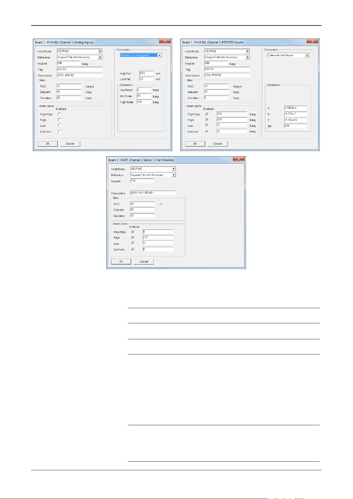
Config600 Configuration Software User Manual
Field
Description
Measured
Use the derived calculated value from the incoming
signal.
Keypad
Use the keypad value in place of the calculated value.
Note: This is the default value.
Last Good
Use the last valid value received from the incoming
signal.
Average
Use the rolling average of the last two “good” readings
healthy.
Weighted
Use the rolling time/flow weight average of the signal.
6.2.8, Time & Flow Weighted Averaging.
Figure 4-7. Analog Input, PRT/RTD, and HART dialog boxes
3. Select an Initial Mode of operation. Valid values are:
from the incoming signal.
Note: Analog inputs are considered valid if the
measured current is within Centigrade HI and
LO fail limits. PRT/RTD inputs are considered
valid while no integrity fail alarms are present.
HART inputs are considered valid when no
errors are present in the good comms and
second status byte indicates the device is
Note: This mode is valid only if you configure this
input in a time/flow weighted average
calculation table. Refer to Chapter 6, Section
4-8 I/O and Comms Configuration Revised February 2022
Page 83

Config600 Configuration Software User Manual
Field
Description
Disabled
If the input has failed, continue to use this value.
Keypad Fail
If the input has failed, change the value to use the
displays as KEYPAD-F on failure.
Average Fail
If the input has failed, change the value to use the
displays as AVERAGE-F on failure.
Last Good Fail
If the input has failed, change the value to use the last
LASTGOOD-F on failure.
Keypad Fail no
If the input has failed, change the value to use the
changed. This mode displays as KEYPAD-F on failure.
Average Fail no
If the input has failed, change the value to use the
failure.
Last Good Fail
If the input has failed, change the value to use the
failure.
Weighted Fail
If the input has failed, change the value to use the
WEIGHTED-F on failure
Weighted Fail
If the input has failed, change the value to use the
WEIGHTED-F on failure.
4. Select a Behaviour value. Valid values are:
with Recovery
with Recovery
with Recovery
Recovery
Recovery
no Recovery
Keypad value. When the input has recovered, the
system reverts to its previous mode. This mode
average value. When the input has recovered, the
system reverts to its previous mode. This mode
valid value. When the input has recovered, the system
reverts to its previous mode. This mode displays as
Keypad value. When the input has recovered, the
system remains in Keypad mode until manually
Average value. When the input has recovered, the
system remains in Average mode until manually
changed. This mode displays as AVERAGE-F on
Lastgood value. When the input has recovered, the
system remains in Lastgood mode until manually
changed. This mode displays as LASTGOOD-F on
no Recovery
with Recovery
Time / Flow weighted value. When the input has
recovered, the system remains in Average mode until
manually changed. This mode displays as
Time / Flow weighted value. When the input has
recovered, the system reverts to its previous mode
until manually changed. This mode displays as
5. Enter a Keypad value. The system uses this value either if the
Initial Mode is set to Keypad or the input has failed and the
Behaviour value is set to Keypad Fail (with or without recovery).
6. Enter an item Tag of up to 12 alphanumeric characters. The system
uses this on the front panel of the S600+.
7. Enter an item Description of up to 20 alphanumeric characters.
The system uses this description on reports, alarm printouts, and
displays.
8. Enter a Rate of Change (ROC) value. If, in one second, the input
variable changes by an amount greater than this value and you
have enabled alarms (Advanced Setup > Alarms), Config600
alarms the operator.
9. Enter values for Setpoint and Deviation. Config600 uses these
values if the operator is required to know when the input variable
Revised February 2022 I/O and Comms Configuration 4-9
Page 84

Config600 Configuration Software User Manual
Value
Description
0–20mA
Use if you apply a current input directly to the I/O board.
4–20mA
Use if you apply a current input directly to the I/O board.
0–5V
Use if you apply a voltage signal directly to the I/O
resistor and apply the derived voltage to the I/O board.
1–5V
Use if you apply a voltage signal directly to the I/O
resistor and apply the derived voltage to the I/O board.
0–20mA 2
Use if you apply a current input directly to the I/O
front panel.
4–20mA 2
Use if you apply a current input directly to the I/O
front panel.
0–5V 2 point
Use if you apply a voltage signal directly to the I/O
front panel.
1–5V 2 point
Use if you apply a voltage signal directly to the I/O
front panel.
has changed. The Setpoint field provides a check value, and the
Deviation field indicates the allowed variance.
Note: Config600 can raise an alarm only if you have previously
enabled Alarms in Advanced Setup.
10. Define Alarm Limits. If you enable an alarm, set a threshold value
for that alarm.
On the High and High High alarms, Config600 raises the alarm if
the in-use value rises above the entered threshold value. On the
Low and Low Low alarms, Config600 raises an alarm if the in-use
value falls below the entered threshold value.
11. Select a Conversion value:
If analog, click to select a valid Conversion value:
point eng
units
point eng
units
eng units
board or if you place a current loop across a 250-ohm
board or if you place a current loop across a 250-ohm
board with on-line calibration when the transmitter
has a straight-line response but an offset is
required.
Note: This option enables you to enter Low Scale,
High Scale, and Offset values on the S600+
board with on-line calibration when the transmitter
has a straight-line response but an offset is
required.
Note: This option enables you to enter Low Scale,
High Scale, and Offset values on the S600+
board or when you place a current loop across a 250ohm resistor and apply the derived voltage to the I/O
board with on-line calibration when the transmitter has a
straight-line response but an offset is required.
Note: This option enables you to enter Low Scale,
High Scale, and Offset values on the S600+
eng units
4-10 I/O and Comms Configuration Revised February 2022
board or when you place a current loop across a 250ohm resistor and apply the derived voltage to the I/O
board with on-line calibration when the transmitter has a
straight-line response but an offset is required.
Note: This option enables you to enter Low Scale,
High Scale, and Offset values on the S600+
Page 85

Config600 Configuration Software User Manual
Value
Description
0–20mA 3
Use if you apply a current input directly to the I/O board
webserver.
4–20mA 3
Use if you apply a current input directly to the I/O board
webserver.
0–5V 3 point
Use if you apply a voltage signal directly to the I/O
webserver.
1–5V 3 point
Use if you apply a voltage signal directly to the I/O
webserver.
0–20mA 2
Use if you apply a current input directly to the I/O board
mA, and Offset values on the S600+ front panel.
4–20mA 2
Use if you apply a current input directly to the I/O board
mA, and Offset values on the S600+ front panel.
0–5V 2 point
Use if you apply a voltage signal directly to the I/O
mA, and Offset values on the S600+ front panel.
1–5V 2 point
Use if you apply a voltage signal directly to the I/O
mA, and Offset values on the S600+ front panel.
0–20mA 3
Use if you apply a current input directly to the I/O board
webserver.
point eng
units
point eng
units
eng units
eng units
with on-line calibration when the transmitter does not
have a straight-line response.
Note: This option enables you to perform a three-point
field calibration on the S600+ front panel or
with on-line calibration when the transmitter does not
have a straight-line response.
Note: This option enables you to perform a three-point
field calibration on the S600+ front panel or
board or if you place a current loop across a 250-ohm
resistor and apply the derived voltage to the I/O board
with on-lline calibration when the transmitter does not
have a straight-line response.
Note: This option enables you to perform a three-point
field calibration on the S600+ front panel or
board or if you place a current loop across a 250-ohm
resistor and apply the derived voltage to the I/O board
with on-lline calibration when the transmitter does not
have a straight-line response.
Note: This option enables you to perform a three-point
field calibration on the S600+ front panel or
point mA
point mA
mA
mA
with on-line calibration when the transmitter has a
straight-line response but an offset is required.
Note: This option enables you to enter Low mA, High
with on-line calibration when the transmitter has a
straight-line response but an offset is required.
Note: This option enables you to enter Low mA, High
board or when you place a current loop across a 250ohm resistor and apply the derived voltage to the I/O
board with on-lline calibration when the transmitter has
a straight-line response but an offset is required.
Note: This option enables you to enter Low mA, High
board or when you place a current loop across a 250ohm resistor and apply the derived voltage to the I/O
board with on-lline calibration when the transmitter has
a straight-line response but an offset is required.
Note: This option enables you to enter Low mA, High
point mA
Revised February 2022 I/O and Comms Configuration 4-11
with on-lline calibration when the transmitter does not
have a straight-line response.
Note: This option enables you to perform a three-point
field calibration on the S600+ front panel or
Page 86

Config600 Configuration Software User Manual
Value
Description
4–20mA 3
Use if you apply a current input directly to the I/O board
webserver.
0–5V 3 point
Use if you apply a voltage signal directly to the I/O
webserver.
1–5V 3 point
Use if you apply a voltage signal directly to the I/O
webserver.
Value
Description
DIN
Converts the incoming resistance reading into
385 curve).
American
Converts the incoming reading into temperature using
the standard IPTS-68 (using the 392 curve).
DIN Offset
Converts the incoming resistance reading into
on the S600+ front panel or webserver.
American
Converts the incoming reading into temperature using
on the S600+ front panel or webserver.
Linear Cal
Converts the incoming resistance reading to
webserver.
Non Linear
Converts the incoming resistance reading to
webserver.
point mA
mA
mA
with on-lline calibration when the transmitter does not
have a straight-line response.
Note: This option enables you to perform a three-point
field calibration on the S600+ front panel or
board or if you place a current loop across a 250-ohm
resistor and apply the derived voltage to the I/O board
with on-line calibration when the transmitter does not
have a straight-line response.
Note: This option enables you to perform a three-point
field calibration on the S600+ front panel or
board or if you place a current loop across a 250-ohm
resistor and apply the derived voltage to the I/O board
with on-line calibration when the transmitter does not
have a straight-line response.
Note: This option enables you to perform a three-point
field calibration on the S600+ front panel or
Note: Refer to Appendix D, Field Calibration for additional
information.
If PRT/RTD, click to select a valid Conversion value:
temperature using the standard DIN 43760 (using the
temperature using the standard DIN 43760 (using the
385 curve). Used for on-line calibration where the offset
is added to the measured temperature.
Note: This option enables you to enter an offset value
Offset
the standard IPTS-68 (using the 392 curve). Used for
on-line calibration where the offset is added to the
measured temperature.
Note: This option enables you to enter an offset value
temperature using the American two-point calibration
constants.
Note: This option enables you to perform a two-point
field calibration on the S600+ front panel or
Cal
4-12 I/O and Comms Configuration Revised February 2022
temperature using the American three-point calibration
constants.
Note: This option enables you to perform a three-point
field calibration on the S600+ front panel or
Page 87

Config600 Configuration Software User Manual
Value
Description
Calendar Van
Converts incoming resistance to temperature using the
constants from those standards.
Value
Description
High Scale
Indicates, in mA or V (depending on the selected
calibration.
Mid Scale
Indicates, in mA or V (depending on the selected
calibration.
Low Scale
Indicates, in mA or V (depending on the selected
calibration.
High Fail
In current modes, indicates the direct reading of the
resistor to achieve the required fail voltage.
Low Fail
Indicates, in mA or V (depending on the selected
or 20 mA).
Value
Description
Low Scale
Indicates, in mA or V (depending on the selected
calibration.
Mid Scale
Indicates, in mA or V (depending on the selected
calibration.
Dusen
Calendar Van Dusen A, B, C, and R0 constants. Use
this option to select other tables (such as IEC) by
entering the A, B, C, or R0 constants.
Note: Select the Calendar Van Dusen option to
support other temperature curves (such as DIN
43760 1980 or IEC 60751 2008) when using
12. Complete any conversion-specific fields for the analog conversion
value you selected:
Note: Conversion settings in this section may require that you
change jumper (bit link) settings on the appropriate I/O
board. Refer to the FloBoss S600+ Flow Computer
Instruction Manual (Form A6115) for further details.
conversion option), the high-range scaling value (5 V
or 20 mA).
Note: This field does not display for on-line
conversion option), the middle-range scaling value (5
V or 20 mA).
Note: This field does not display for on-line
conversion option), the low-range scaling value (0 V,
1 V, 0 mA, or 4 mA).
Note: This field does not display for on-line
Analog Input at which the transmitter has failed.
In voltage modes, indicates (in mA) the current
required to pass through a 250-ohm conditioning
conversion option), the mid-range scaling value (5 V
13. Complete any required calibration-specific fields for the
conversion factor you selected.
If Analog:
conversion option), the low-range scaling value (0 V,
1 V, 0 mA, or 4 mA).
Note: This field does not display for on-line
Revised February 2022 I/O and Comms Configuration 4-13
conversion option), the mid-range scaling value (5 V
or 20 mA).
Note: This field does not display for on-line
Page 88

Config600 Configuration Software User Manual
Value
Description
High Scale
Indicates, in mA or V (depending on the selected
calibration.
Value
Description
Low Scale
Indicates, in degrees Centigrade, the low value for
options.
Mid Scale
Indicates, in degrees Centigrade, the mid value for
Non Linear Cal conversion option.
High Scale
Indicates, in degrees Centigrade, the high value for
options.
A
Provides the A constant value for the Calendar Van
Calendar Van Dusen conversion option.
B
Provides the B constant value for the Calendar Van
Calendar Van Dusen conversion option.
C
Provides the C constant value for the Calendar Van
Calendar Van Dusen conversion option.
R0
Provides the R0 constant value for the Calendar Van
Calendar Van Dusen conversion option.
Value
Description
High High
Select the checkbox and enter a value to which the
input value must rise to generate a High High alarm.
High
Select the checkbox and enter a value to which the
input value must rise to generate a High alarm.
Low
Select the checkbox and enter a value to which the
input value must lower to generate a Low alarm.
Low Low
Select the checkbox and enter a value to which the
alarm.
If PRT/RTD:
conversion option), the high-range scaling value (5 V
or 20 mA).
Note: This field does not display for on-line
calibration.
Note: This field displays only if you select the
Linear Cal or Non Linear Cal conversion
calibration.
Note: This field displays only if you selected the
calibration.
Note: This field displays only if you selected the
Linear Cal or Non Linear Cal conversion
Dusen conversion.
Note: This field displays only if you selected the
Dusen conversion.
Note: This field displays only if you selected the
Dusen conversion.
Note: This field displays only if you selected the
Dusen conversion.
Note: This field displays only if you selected the
14. Complete any Alarm Limit values:
15. Click OK to apply the edits. The PCSetup screen displays.
4-14 I/O and Comms Configuration Revised February 2022
input value must lower to generate a Low Low
Page 89

Config600 Configuration Software User Manual
4.3.3 Adding a New I/O Point
To add either a new analog input or a new PRT/RTD I/O point:
1. Right-click in the right-hand pane of the PCSetup screen. The
system displays a shortcut menu.
2. Select New I/O Point on the shortcut menu. The system displays
the Analog Input Assignment dialog box.
3. Complete the Type, I/O Board, I/O Channel, and Units fields as
described in Editing Analog Inputs.
Note: Config600 highlights the default values for each field. You
4. Select the type of Units.
5. Click OK to apply the new I/O point to your configuration. The
system redisplays the PCSetup screen with your new I/O point.
4.4 Analog Outputs (AO)
You can assign each analog output channel to an individual data item.
You can also assign individual data items to more than one output,
which allows you to create a repeat signal.
Each installed I/O module (P144) provides up to four analog output
channels. Neither the Prover module (P154) nor the HART module
(P188) provide any analog output channels.
Figure 4-8. Analog Input Assignment dialog box
can accept or change those defaults as necessary.
4.4.1 Editing Analog Outputs
To edit an analog output data item:
1. Select Analog Outputs from the hierarchy menu. The system
displays all currently defined analog outputs in the right-hand pane.
Revised February 2022 I/O and Comms Configuration 4-15
Page 90

Config600 Configuration Software User Manual
2. Double-click an analog output to edit. The Analog Output
Assignment dialog box displays.
3. Select the Item Type to assign the Analog Output (or select
Unassigned to deselect the output). Config600 completes the Item
field with available data items:
Figure 4-9. Analog Output Items
4. Select an item in the Item field to assign to the item type.
5. Define the output scales by entering values in the Low scale and
High scale fields. S600+ uses these values when converting the
raw value into a scaled analog output value. The default value for
the Low scale is 0; the default value for the High scale is
10000000. To invert the output, set the High scale lower than the
Low scale.
Note: Config600 changes the units associated with these fields
(kg/m3, t/h, m3/h, pls/m3, and such) based on the data item
you select.
6. Select a Conversion factor for the Low scale and High scale
values. Valid options are 0 to 20mA or 4 to 20mA. The default is 4
to 20mA. For example, if you select the 4 to 20mA option,
Config600 equates the Low scale value to 4 mA and the High scale
value to 20mA.
7. Click OK to apply your selections. The system redisplays the
PCSetup screen with your new assignments.
Note: Refer to Appendix D, Field Calibration, for additional
information.
4-16 I/O and Comms Configuration Revised February 2022
Page 91

4.5 Density Inputs
Config600 Configuration Software User Manual
Config600 supports either single or twin densitometers, which you
assign to each station or stream as you develop a configuration. You
can assign each densitometer frequency to a specific density input
channel on the I/O module.
Each installed I/O module (P144) provides three available density
input channels. Each installed Prover module (P154) provides two
channels.
Notes:
If the densitometer also acts as the temperature element for the
meter, assign the meter temperature, densitometer temperature, and
pressure transmitter to the same analog input.
Using the Streams option in the PCSetup Editor, you can switch a
frequency input to an analog signal. See Chapter 6, Stream
Configuration.
4.5.1 Assigning Density Input
To assign or reassign a density input data item:
1. Select Density Inputs from the hierarchy menu. The system
displays all currently defined density inputs in the right-hand pane.
2. Double-click a Density Input to edit. The Assign Input dialog box
displays.
Note: You can also click the Assignment icon on the toolbar
to display the dialog box.
3. Select the I/O Board to assign the density input (or select
Unassigned to deselect the input). Config600 lists available
channels in the I/O Channel field:
Figure 4-10. I/O Channels for Density Input
Revised February 2022 I/O and Comms Configuration 4-17
Page 92

Config600 Configuration Software User Manual
4. Select the I/O Channel for the density input.
5. Click OK to apply the assignment. The system redisplays the
PCSetup screen with your new I/O assignment.
Notes:
Before displaying the PCSetup screen, Config600 may display
a reminder for you to enable the alarms for the new assignment.
When you assign a densitometer input, the station or stream
density configuration page displays.
Figure 4-11. Alarm Reminder
4.5.2 Editing Density Inputs
To edit the description for a density data item:
1. Select Density Inputs from the hierarchy menu. The system
displays all currently defined density inputs in the right-hand pane.
2. Right-click a data item to edit. The system displays a shortcut
menu.
3. Select Settings on the shortcut menu. The system displays the Edit
Description dialog box:
Figure 4-12. Edit Description dialog box
4. Edit the current item description, using no more than 20
alphanumeric characters.
5. Click OK to apply the new item description. The system redisplays
the PCSetup screen with your new item description.
4-18 I/O and Comms Configuration Revised February 2022
Page 93

4.6 Turbine Inputs
The S600+ cannot count pulses unless the I/O module (P144) or Prover
module (P154) is fitted with a dual-pulse P148 mezzanine board.
Field
Description
Unassigned
Select to un-assign a pulse input.
Single
Select if only one pulse train is available from the
meter.
Dual Level A
Select if the meter provides dual pulses at the same
accordance with ISO 6551 (IP252/76).
Caution
4.6.1 Assigning Turbine Inputs
Config600 Configuration Software User Manual
A turbine or positive displacement meter provides inputs to the system
in the form of single-pulse or dual-pulse data. You assign the turbine
pulse inputs to an I/O channel on the I/O board.
Each installed I/O module (P144) or Prover module (P154) provides up
to four pulse input channels. You can define these channels as:
Four single-pulse inputs.
Two dual-pulse inputs.
Two single-pulse and one dual-pulse inputs.
To assign or reassign turbine input data items:
1. Select Turbine Inputs from the hierarchy menu. The system
displays all currently defined turbine inputs in the right-hand pane.
2. Double-click a turbine input to edit. The Pulse Input Assignment
dialog box displays.
Note: You can also click the Assignment icon on the toolbar
to display the dialog box.
Figure 4-13. Pulse Input Assignment dialog box
3. Select a pulse mode:
frequency but out of phase.
Note: This option conforms to Level A interpolation in
Revised February 2022 I/O and Comms Configuration 4-19
Page 94

Config600 Configuration Software User Manual
Field
Description
Dual Level B
Select if the meter provides dual pulses at the same
accordance with ISO 6551 (IP252/76).
Field
Description
Reset
Determines the number of consecutive valid pulses the
Frequency field.
Bad Pulse
Indicates the number of bad pulses that need to
raises the bad pulse alarm. The default is 50.
Field
Description
Bad Pulse
Defines how the system manages the bad pulse
Clear.
Error Check
Sets a threshold input frequency value. While
value, it does not include them in bad pulse checking.
4. Select the I/O board for the pulse turbine input.
5. Select an I/O channel to use.
For dual-pulse input on the I/O (P144) module, select channels
1 & 2 or 3 & 4.
For dual-pulse input on the Prover (P154) module, select
channels 2 & 3 or 4 & 5 (Config600 reserves channel 1 for the
I/O board).
Four channels (1, 2, 3, and 4 for I/O modules or 2, 3, 4, and 5
for Prover modules) are available for single-pulse inputs.
6. Complete the Low Frequency Cutoff field using a Hertz value. If
the S600+ receives pulse frequencies below this value, it sets the
flow rate and input frequency to zero.
frequency but out of phase.
Note: This option conforms to Level B interpolation in
Note: Totalisation still occurs in Liquid Turbine applications, but
does not occur in Gas Turbine applications when the
frequency is below the Low Frequency Cutoff value.
7. Complete the fields in the Thresholds pane (which displays only if
you selected Dual Level A or B as a pulse mode).
system must receive after the occurrence of the bad
pulse alarm before it clears the bad pulse alarm. The
default value is 200000.
Note: Config600 ignores all bad pulses that occur
below the value you enter in the Error Check
accumulate in the bad pulse buffer before the system
8. Complete the fields in the Bad Pulse Configuration pane (which
displays only if you selected Dual Level A or B as a pulse mode).
Reset Mode
buffer. Valid values are Clear (clear the buffer when
the input frequency is below the error check frequency)
or Set (do not clear the buffer). The default value is
Frequency
9. Click OK to apply the assignments. The PCSetup screen displays
showing your new values.
4-20 I/O and Comms Configuration Revised February 2022
Config600 detects and records pulses below this
Page 95

Config600 Configuration Software User Manual
4.6.2 Editing Turbine Inputs
To edit the description for a pulse input data item:
1. Select Turbine Inputs from the hierarchy menu. The system
displays all defined turbine Inputs.
2. Right-click a data item to edit. The system displays a shortcut
menu.
3. Select Settings on the shortcut menu. The system displays the Edit
Description dialog box:
Note: You can also click the Settings icon on the toolbar after
highlighting the data item to display the menu.
4.7 Pulse Outputs
Figure 4-14. Edit Description dialog box
4. Edit the current item Description, using no more than 25
alphanumeric characters.
5. Click OK to apply the new item Description. The system
redisplays the PCSetup screen with your new item Description.
Use pulse outputs to derive cumulative totals for display on a counter,
a totaliser, or DCS system. You can assign each pulse output to a
specific pulse output channel on the I/O board.
Each installed I/O (P144) module provides five pulse output channels,
and each installed Prover (P154) module provides four channels.
Figure 4-15. Pulse Output Items
Revised February 2022 I/O and Comms Configuration 4-21
Page 96
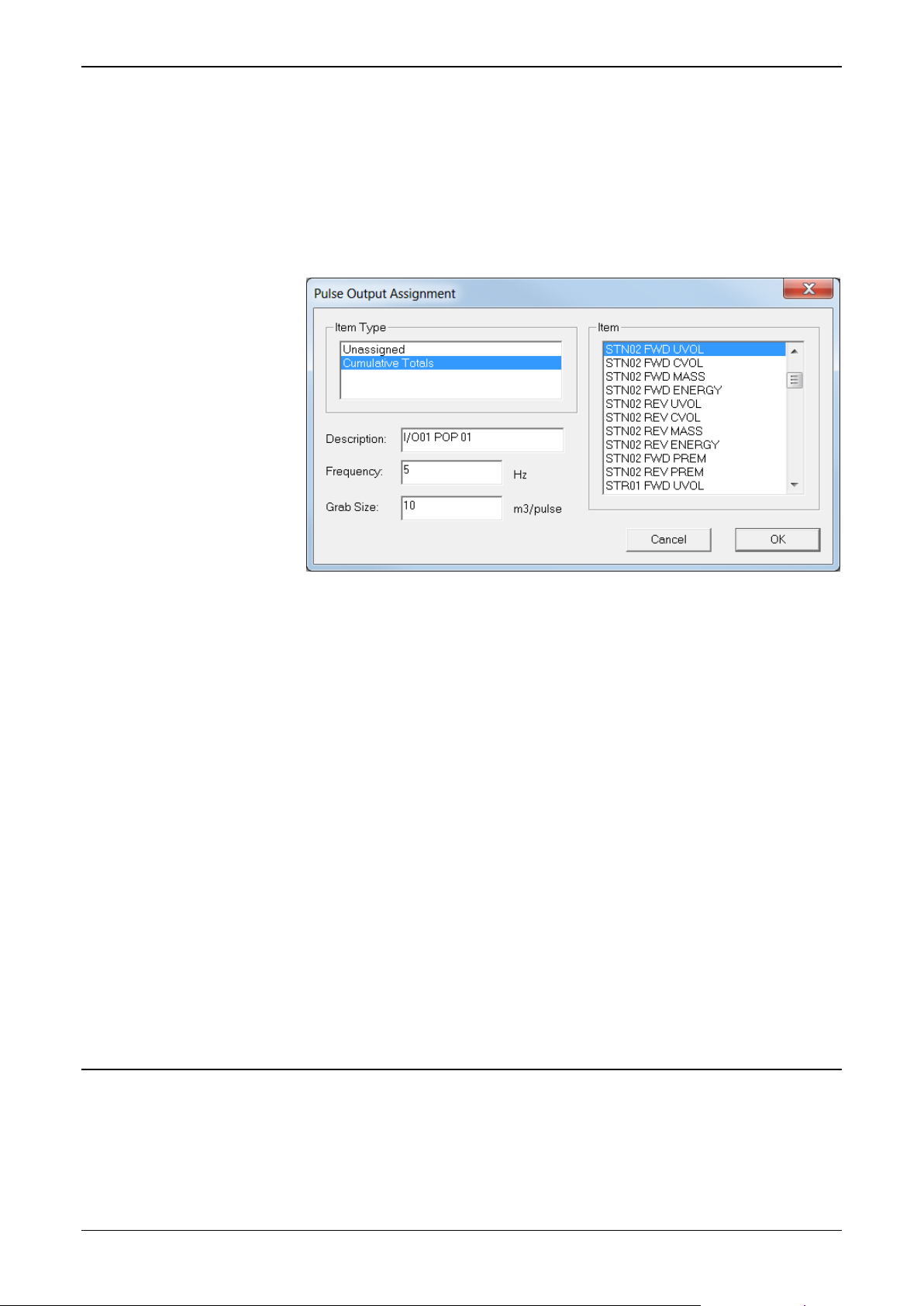
Config600 Configuration Software User Manual
4.7.1 Assigning Pulse Outputs
To assign or reassign Pulse Output data items:
1. Select Pulse Outputs from the hierarchy menu. The system
displays all defined pulse output data items.
2. Double-click a pulse output to edit. The Pulse Output Assignment
dialog box displays.
Figure 4-16. Pulse Output Items
3. Select Cumulative Totals in the Item Type pane. Config600
completes the Item field with available items.
4. Select an Item in the Item pane to associate with the Pulse Output.
5. Edit the Description associated with the item and item type.
Config600 uses this value only on screen displays and reports.
6. Complete the Frequency field using a Hertz value to indicate the
output’s pulse width. For example, a frequency of 5 Hz equates to a
200 millisecond pulse width with a 50/50 duty cycle. The default
value is 5.
7. Complete the Grab Size field to indicate the number of units per
pulse (the type of unit being dependent on the application)
Config600 accumulates before sending a pulse. For example, use a
Grab Size value of 10m3 to measure increments in the Cumulative
Volume Totals for each outputted pulse. The default is 10.
8. Click OK to apply the new assignment. The PCSetup screen
displays showing the new assignment.
4.8 HART Modules
Each Highway Addressable Remote Transducer (HART) module
supports 12 channels with up to 8 transmitters per channel. However,
the S600+ has an overall restriction of 50 transmitters.
4-22 I/O and Comms Configuration Revised February 2022
Page 97

Config600 Configuration Software User Manual
Note: You cannot add a HART module definition to an existing
configuration file. If you add a HART module to your S600+,
you must create an entirely new configuration file. Be sure to
assign the I/O module (P144) to address 1 and the HART
module (P188) to address 2.
The S600+ supports 12 channels, with up to 8 sensors multidropped
from each channel. Since each sensor takes approximately 0.5 second
of scan time, the more sensors you add to each channel, the slower the
I/O update time becomes for that channel. Also, the HART module
reads only the HART digital signal, not the channel’s analogue value.
If you require both, you must physically wire the HART signal to an
ADC and HART channel.
By default, the S600+ acts as the primary HART master. Ensure there
is no other primary master connected to the channel. For dual master
support or instructions on how to set the S600+ to secondary master,
contact Technical Support.
4.8.1 Editing HART Settings
To edit or reassign settings for the HART data items:
1. Select HART Boards from the hierarchy menu. The system
displays the HART Board configuration screen:
Figure 4-17. HART Module Configuration screen
2. Complete the screen based on the number of sensors associated
with each channel on the S600+. Click ▼ to display valid values.
4.9 PID Loop Settings
The PID control task provides primary control with secondary override
control (that is, two control loops, each with its own parameters). You
can either select the output according to criteria you can enter or allow
a status input to the task to select the output.
You can configure an individual PID task for each station and stream,
subject to the I/O providing sufficient analog outputs.
Revised February 2022 I/O and Comms Configuration 4-23
Page 98

Config600 Configuration Software User Manual
Typically, a liquid application has flowrate primary control which
changes to pressure control if the pressure falls too low. A gas
application has a primary pressure control which is overridden by flow
control if the flowrate becomes too high.
4.9.1 Assigning PID Loops
To assign or reassign PID data items:
1. Select PID Loops from the hierarchy menu. The system hides the
setup fields until you assign an analog output to the PID loop (see
Figure 4-18).
Figure 4-18. PID Loop Enabled screen
2. Select Unassigned (or select the Analog Outputs from the
hierarchy menu) to identify the Analog Output values you desire to
associate with each PID control loop.
Figure 4-19. Analog Output Assignment screen
4-24 I/O and Comms Configuration Revised February 2022
Page 99

Config600 Configuration Software User Manual
3. Select PID Loops from the hierarchy menu. The system expands
the hierarchy to display the control loops defined for each I/O
module.
4. Select a control loop. Config600 displays the common data items
for this loop.
Figure 4-20. PID Loop Output Assigned screen
5. Assign the Primary Controlled Process Variable to enable the
primary controller.
6. Click PV Channel Settings. A Select Object dialog box displays.
Use it to assign the Analog Output value associated with this PID
control loop.
Figure 4-21. PID Loop Output Assigned screen
7. Assign – if required – the Override Controller process variable.
Config600 expands the screen content.
Revised February 2022 I/O and Comms Configuration 4-25
Page 100

Config600 Configuration Software User Manual
Field
Description
Disable
The PID algorithm does not execute and the output
does not update
Dual Auto
Selects Primary control with Secondary override
field.
Primary Only
Uses the primary control settings with no switching to
secondary control.
Secondary
Only
Uses the second control settings; does not switch to
primary control.
User Logic
Uses a KPINT status input to select either primary or
downloaded from a supervisory computer.
Figure 4-22. PID Loop PV Assigned screen
8. Select the Control Method for the PID loop. Click ▼ to display all
valid process variable values.
according to the settings defined in Switch Over Logic
secondary control. The status can be set by an
operator, a digital input, user logic in a LogiCalc, or
9. Complete the Auto/Manual field. Valid values are Manual (the
system forces the output to the Manual Position value) or Auto (the
system uses the calculated value from the PID algorithm to drive
the analog output). The default value is Manual.
10. Indicate an MV Max Rate Of Change as a percentage of the
output per second. This value controls the Manipulated Variable
output’s maximum rate of change (ROC). The default is 60 (60%
of output). For example, entering 20 in this field limits a full range
(0 to 100) change to a minimum of 5 seconds.
Note: Enter 0 in the MV Max Rate of Change field to override the
11. Indicate an MV Clamping High Limit as a percentage of the
output. This value limits the Manipulated Variable output’s
maximum value. The default is 100.
4-26 I/O and Comms Configuration Revised February 2022
field.
 Loading...