

Page 1

P
D
I
An Introduction to:
ACCOL
(Formerly known as "The ACCOL Textbook")
DEVICE
INITIAL
Bristol Babcock
D4056 Issue: January, 2001
Page 2

Notice
Copyright Notice
The information in this document is subject to change without notice. Every effort has been
made to supply complete and accurate information. However, Bristol Babcock assumes no
responsibility for any errors that may appear in this document.
Bristol Babcock does not guarantee the accuracy, sufficiency or suitability of the software
delivered herewith. The Customer shall inspect and test such software and other materials to
his/her satisfaction before using them with important data.
There are no warranties, expressed or implied, including those of merchantability and fitness
for a particular purpose, concerning the software and other materials delivered herewith.
Request for Additional Instructions
Additional copies of instruction manuals may be ordered from the address below per attention
of the Sales Order Processing Department. List the instruction book numbers or give the
complete model, serial or software version number. Furnish a return address that includes
the name of the person who will receive the material. Billing for extra copies will be according
to current pricing schedules.
ACCOL is a trademark and Bristol is a registered trademark of Bristol Babcock. Other
trademarks or copyrighted products mentioned in this document are for information only, and
belong to their respective companies, or trademark holders.
Copyright (c) 2001, Bristol Babcock, 1100 Buckingham St., Watertown, CT 06795. No part of
this manual may be reproduced in any form without the express written permission of Bristol
Babcock.
Page 3

A Few Words About Bristol Babcock
For over 100 years, Bristol® has been providing innovative solutions for the measurement
and control industry. Our product lines range from simple analog chart recorders, to
sophisticated digital remote process controllers and flow computers, all the way to turnkey
SCADA syst em s . Over t he y ea r s , we have bec om e a l ea d i ng supplier to the electronic gas
measurement, water puri f ication, a nd wast ew a ter tr ea tment ind us tries.
On off-shore oil platforms, on natural gas pipelines, and maybe even at your local water
company, there ar e Br i s tol Babcoc k instr um ents, controllers , and sy s tems running y ea r - in
and year-out to provide accurate and timely data to our customers.
Getting Additional Information
In addition to the information contained in this manual, you may receive additional
assistance in using Bristol Babcock products from the following sources:
Contacting Bristol Babcock Directly
Bristol Babcock's world headquarters are located at 1100 Buckingham Street, Watertown,
Connecticut 06795, U.S.A. Our main phone numbers are:
(860) 945-2200
(860) 945-2213 (FAX)
Regular office hours are Monday through Friday, 8:00AM to 4:30PM Eastern Time, excluding
holidays a nd scheduled fact or y s hutdowns. During ot her hours, ca l ler s may leav e m es sages
using Bristol's voice mail system.
Telephone Support - Technical Questions
During regular business hours, Bristol Babcock's Application Support Group can provide
telephone support f or y our technical q uestions.
For technical questions regarding ACCOL, ACCOL Workbench, Open BSI products
(as well as ACCOL DOS-based Tools, or UOI) call (860) 945-2286. Before you call,
please fi nd out the version of software you a r e us i ng .
For technical questions regarding Bristol's OpenEnterprise product, call (860) 945-2501 or
e-mail openenterprise@bristolbabcock.com
For technical questions regarding Bristol's Enterprise Server® / Enterprise
Workstation® products, call (860) 945-2286.
For technical questions regarding Network 3000 hardware products call (860) 945-2502.
For technical questions about ControlWave call (860) 945-2244 or (860) 945-2286.
You can e-mail the Application Support Group at: bsupport@bristolbabcock.com
The Application Support Group also maintains a bulletin board for downloading software
updates to customers. To access the bulletin board, dial (860) 945-2251 (Modem settings:
14.4K baud maximum, No parity, 8 data bits, 1 Stop bit . )
i
Page 4

For assistance in interfacing Bristol Babcock hardware to radios, contact Communication
Technologies in Orlando, FL at (407) 629-9463 or (407) 629-9464.
Telephone Support - Non-Technical Questions, Product Orders, etc.
Questions of a non- technical na ture (pr od uc t orders , liter a ture requests, p r i c e a nd delivery
information, etc.) shoul d b e directed to the nea r es t regional s a l es of f i c e ( l isted bel ow ) or to
your local Bristol sales office or Bristol-authorized sales representative.
U.S. Regi on al Sales Offices Principal International S ales Offices:
Northeast (Watertown) (860) 945-2262 Bristol Babcock Ltd (UK): (441) 562-820-001
Southeast (Birmingham) (205) 980-2010 Bristol Babcock, Canada: (416) 675-3820
Midwest (Chicago) (630) 571-6052 Bristol Meci SA (France): (33) 2-5421-4074
Western (Los Angeles) (909) 923-8488 Bristol Digital Sys. Australasia Pty. Ltd.
Southwest (Houston) (713) 685-6200 BBI, S.A. de C.V. (Mex ic o) (525) 254-2131
61 8-9455-9955
Please call the main Bristol Babcock number (860-945-2200) if you are unsure which office
covers your particular area.
Visit our Site on the World Wide Web
For general information about Bristol Babcock and its products, please visit our site on the
World Wide Web at: www.bristolbabcock.com
Training Courses
Bristol Babcock’s Training Department offers a wide variety of courses in Bristol hardware
and software at our Watertown, Connecticut headquarters, and at selected Bristol regional
offices, throughout the year. Contact our Training Department at (860) 945-2343 for course
information, enrollment, pricing, and schedules.
ii
Page 5

Who Should Read This Manual?
This manual i s intended for use by new ACCOL users. It describes the b asic
concepts in ACCOL, and provides examples of the major structures used by the
ACCOL programmer.
It assumes familiarity with the following subjects:
Use of personal computers, including clicking with a mouse, using di alog
boxes, list boxes, menus, etc.
Windows 98 or Windows NT operating system.
As a minimum, users should have the fol lowing additional manuals available, when
reading this manual:
ACCOL II Reference Manual (document# D4044) which contains detailed
descriptions of all ACCOL modules.
ACCOL Workbench U ser Manual (document# D4051) which contains detailed
instructions on using ACCOL Workbench to create an ACCOL load.
Network 3000 Communications Configuration Guide (document# D5080)
which contains an overview of communications using Bristol Babcock
networks, and a guide to troubleshooting communication problems.
NOTE
This book should not be considered a substitute for ’handson’ experience with ACCOL Workbench and Network 3000
controllers.
New users should strongly consider attending one or more
training courses offered by Bristol Babcock. Contact our
Training Department at the number listed on page ii for
more information.
iii
Page 6

BLANK PAGE
Page 7

Table of Contents
Chapter 1 - What is ACCOL?
Chapter 2 - What Are Signals?
Chapter 3 - What Are Modules?
Chapter 4 - What Are ACCOL Tasks?
Chapter 5 - What Are Data Arrays?
Chapter 6 - What Is Process I/O?
Chapter 7 - How Are Communication Ports Used?
Chapter 8 - What Should I Know About Memory?
Chapter 9 - What Are Signal Lists?
Chapter 10 - What Are Archive Files?
Appendix A - Creating A Sample ACCOL Load
.....................................................................................
..................................................................................
.................................................................................
.......................................................................
..........................................................................
...............................................................................
...........................................................................
.....................................................................
.......................................................
...................................................
...................................................
1-1
2-1
3-1
4-1
5-1
6-1
7-1
8-1
9-1
10-1
A-1
Appendix B - Working with Floating Point Numbers
Glossary
......................................................................................................................
..............................................
B-1
G-1
v
Page 8

BLANK PAGE
Page 9

Chapter 1 - Introduction: What is ACCOL?
What is ACCOL?
ACCOL
dvanced Communications and Control-
A
riented Language. The initial concept for
O
is an acronym which stands for
ACCOL was developed at Bristol in the
early 1970s, and has since become the
standard software programming language
for Bristol Babcock Network 3000-series
devices. Several newer generations of the
language have been developed since then.
The current versions of the ACCOL
language, as well as the
ACCOL Tools
software, which i s used to create programs
in the language, have incorporated
numerous features and improvements
suggested by our customers, and are
markedly different from the initial version.
All are rooted in the initial concept of
ACCOL, however, which was to create a
high-level programming language which
used a ‘modular’ approach for monitoring
and control of process control applications.
What is Network 3000?
Network 3000
process controllers
3335, RTU 3310, and RTU 3305 remote process controllers, as well as GFC 3308-series
flow computers1 and the EGM 3530-xx TeleFlow™ / RTU 3530-xx TeleRTU series2 flow
computers and RTUs. Network 3000-series controllers are utilized in a wide variety of
measurement and control applications throughout the water, waste water, and natural
gas pipeline industries.
These controllers coll ect data from field instrumentation such as pressure transmitters,
flow meters, electrical contacts and switches. The incoming data is received through
connection points on
1
Network 3000 controllers are often referred to as simply ’33xx controllers’ because of the ’33’ in the model number.
2
3530 TeleFl o w and Te l eRTU uni ts only support a subset o f ACCOL modules an d features. Task slip
counts and rate information, communication statistics, and crash blocks are not available. See the ACCOL
II Reference Manual (D4044) and contac t Bristo l Ba bcock Appl ication Support for mor e infor mation.
3
The term ‘I/O’ is an abbrevi ati on f or input/ out put and ref e rs to data coming i n, and goi ng out, of a partic ul ar
device. The ‘Process I/O board’ is an electronic de v ic e (board/card) in the controlle r through which data comes in and
out from field instrumentation (the process).
is the name for a product family of Bristol Babcock digital
, and auxiliary equipment, which includes the DPC 3330, DPC
process I/O boards
in the controll er.3 Based on th e i n comin g da ta,
remote
An Introduction to ACCOL Page 1-1
Page 10

Chapter 1 - Introduction: What is ACCOL?
the controllers can execute pre-programmed instructions to control a process.
For example, in response to data collected from field instruments, the controller can
issue commands to open valves when a certain pressure is reached, or to start
compressors or pumps if a flow rate decreases below setpoint. All of these preprogrammed instructions are written u sing ACCOL.
In addition to directly controlling a process, a Network 3000 controller can serve as a
node
other controllers.
in a communi cations network . Each controll er (node) can thus share i ts data with
Data is sent to the network through one or more of the controller’s
ports
with cables. Controllers which are far away can communicate through dial-up modems
using either dedicated phone lines or the pu blic teleph one system. For some app lications,
radio or satellite links may be appropriate.
Typically, one or more PC workstations is also connected to the network. These
workstations generally include
programming, as well as
Open BSI Utilities are a collection of programs which facilitate communication with the
controller network by the ACCOL Tools, and by third-party applications. Open BSI
Utilities also allow an operator to collect and view data from the network, and to monitor
the status of network communications. Separate utilities may be purchased which allow
scheduled data collection, and file export capability to third-party applications such as
Microsoft Excel spreadsheets or data bases such as Microsoft Access.
Often, the PC workstations are also equipped with
Acquisition (SCADA)
allow the presentation of data to an operator in the form of graphical displays, trends,
and printed logs or reports. The PC workstation can use one of several different packages
for this purpose including Iconics Genesis software, Intellution® FIX® software, or
Bristol Babcock’s own OpenEnterprise software.
. If controllers are located near each oth er, n etwork con n ection s can be ‘hard-wired’
ACCOL Tools
Open Bristol System Interface (BSI) Utilities
or
Human-Machine Interface (HMI)
software to allow for ACCOL
Supervisory Control and Data
software packages which
communication
software. The
Page 1-2 An Introduction to ACCOL
Page 11

Chapter 1 - Introduction: What is ACCOL?
How Are the Controllers Programmed?
ACCOL programming is done using a set of software programs referred to as the
ACCOL Tools
ACCOL Workbench
necessary functions for ACCOL program generation, with the cut, paste, search, and
replace capabilities of a text editor.
. The most important program in the ACCOL Tools software set is
. ACCOL Workbench, is a Windows-based tool wh ich combines the
The ACCOL programmer uses ACCOL Workben ch to construct an
The ACCOL source file con sists of
ASCII
text, and has a file extension of (.ACC).
ACCOL source file
When editing the source file, the programmer selects from a large set of pre-programmed
ACCOL software
module
the source file. These modules and statements perform common mathematical,
communication, and process control functions.
template s and
control statements
5
which can be inserted in
Each module receiv es a series of in put
values, upon which it performs
certain calculations. It then generates
a series of output values which may
be used by other modules. For
example, the PID3TERM module
generates outputs which allow
proportional, integral, and derivative
control over an input value.
Each module includes a set of
module termi nals
and outputs of the module. The name of an ACCOL
numerical value, is entered on the required module terminals.
which are used to specify the inputs
signal
or, in some cases, just a
Signal
s are software
structures which allow d ata to be passed between modules.6 Each signal has a specific
name which should reflect the type of data it holds. For example, if a signal is used to
store the level of water in water tank number 3, the signal should have a name such as
TANK3.WATER.LEVL. Each signal name, as well as certain characteristics associated
with the signal such as its initial value, engineering units, etc. must be defined in the
ACCOL source file. A typical ACCOL source file includes several hundred signals;
however, depending upon the complexity of the system, thousands of signals may be
used.
4
The ACCOL source file can also be edited directly with any ASCII text editor. AccolCAD software, available separately
from Bristol Babcock, can also be used to generate the ACCOL source file. Notes For Older Network 3000 Products:
Different methods for program generation exist for older model controllers; these units use an older DOS-based set of
ACCOL Tools which include the ACCOL II Batch Compiler (ABC) and ACCOL II Interactive Compiler (AIC). These
older tools are not discussed in this manual.
5
There are numerous modules and control statements to choose from. For information on particular modules and
control statements see the ACCOL II Ref e renc e Manual (document# D4044).
6
For users familiar with other high-level programming languages such as BASIC or ‘C’, signals can be thought of as
‘variables’. In some industries, they are ref e rred to as ‘tags’.
4
.
An Introduction to ACCOL Page 1-3
Page 12

Chapter 1 - Introduction: What is ACCOL?
By entering the same signal name on terminals of different modules, a connection
between the modules is estab lished , and the mod ules are said to be ‘wired’ tog ether.
7
In
this wa y, the outp ut of one mo dul e serve s as the inp ut to a noth er mod ul e; a llo wing d ata
values to be shared between modules.
The programmer combines the appropriate modules and control statements together into
functional blocks called
ACCOL Task
s. ACCOL tasks provide a way to divide up the
source file, and make it more manageable. Although an ACCOL source file can
theoretically include more than 100 tasks, most ACCOL programmers find that using a
few tasks, say less than ten, is most efficient. Each ACCOL task executes at a userdefin ed rate, and wi th a user-def ined priori ty. In this way ta sks which perf orm critical
process control operations can take precedence over tasks which perform less important
calculations.
The ACCOL source file may include other structures which allow for data storage and
management, such as
signal lists
and
data arrays
. These subjects will be discussed
later in this manual.
7
The modules, terminals, signals, and the connections between them all exist in the software program which executes in
the controller. There are no physical modules to be wired together. Unless otherwise noted, whenever these terms are
used in this book, they ref er to soft ware structures in the ACCOL, not physical hardware devices.
Page 1-4 An Introduction to ACCOL
Page 13

Chapter 1 - Introduction: What is ACCOL?
Once the ACCOL source file has been completed,
it must be translated into a format which is
compatible with the Network 3000 series
controller. To perform this translation, the
ACCOL programmer initiates an ACCOL
Workbench ‘build’ command. If there are no
errors in the ACCOL source file, the ‘build’
command generates an intermediate ACCOL
Object File8 (.ACO), and a final ACCOL Load
File (.ACL).
All of the modules and statements originally
entered in the ACCOL source file, are stored as
machine-readable instructions in the ACCOL
Load file. The ACCOL Load file, generally
referred to as simply the
then be
downloaded
into the
ACCOL load
Network 3000-series controller.
memory
9
, may
of the
Once in memory, the controller will begin executing each of the machine-readable
instructions in the ACCOL load, in order to perform whatever measurement and control
duties are required for its particular application.
8
The ACO file is useful only for certain ACCOL Tools, it may NOT be edited by the user.
9
Downloading is performed using the Open BSI Downloader.
An Introduction to ACCOL Page 1-5
Page 14

BLANK PAGE
Page 15

Chapter 2 - What Are Signals?
What Are Signals?
Signals are the primary vehicle by which data is passed from module to module in the
ACCOL load. They are similar to ‘variables’ in other programming languages. The
ACCOL programmer uses signals to specify the inputs to, and outputs from, ACCOL
modules. By placing an ACCOL signal name on a module terminal, that terminal is said
to be ‘wired’ to that signal. Placing that
establishes a connection between the modules; the value of a signal on an output
terminal of one module serves as an input to another module, and so on.
This section will describe the five different types of signals: logical, logical alarm, analog,
analog alarm, and string. A special set of signals created by the system, called
signals
discuss signal naming conventions, and signal characteristics.
will also be discussed. Before covering these topics, however, it’s important to
Signal Naming Conventions
same
signal name on another terminal
system
Every signal has a unique name. Signal names are divided up into three parts as shown
below:
base_name.extension.attribute
The signal
letter.1 The remaining characters can be any mixture of numbers and letters.
The signal
The signal
Note the presence of periods ‘.’ between the base name and extension, and between the
extension and attribute. These serve as separator characters between each part of the
signal name, and are always required. If the signal contains no attribute, the signal
name should include an end ing period, i.e. ‘
nor an attribute is used, the signal name should have two ending periods, i.e. ‘
Here are some examples of valid ACCOL signa l names:
base_name
extension
attribute
can be any mixture of 0 to 4 letters or numbers.
STATION1.TEMP.DEGC
PUMP4.STATUS.
TANK3..LEVL
POWRFAIL..
PUMP3425.STATUS.FAIL
can be from 1 to 8 characters in length, and must begin with a
can be any mixture of 0 to 6 letters or numbers.
base.extension.’
and if neither an extension,
base..’
1
The only exception to this rule is for
‘#’. System signals are created by the ACCOL Tools, and are used for specific ‘housekeeping’ duties. The ACCOL
programmer can use system signals, but cannot create them.
An Introduction to ACCOL Page 2-1
system signals
. All system signals have a base name begi nning with the characte r
Page 16

Chapter 2 - What Are Signals?
The reason signals are divided up into three
parts is that it allows a greater level of
organization for signals.
In the figure, at right, the Open BSI
DataView utility is being used to search for
all signals which share the common
extension ‘LEVEL’. The same type o f search
could be conducted based on base names or
attributes.
Characteristics Common to All Signals
Every ACCOL signal has a set of characteristics associated wi th it. Depending up on the
type of signal (logical, logical alarm, analog, analog alarm, or string) the characteristics
may vary, however, every signal, no matter which type, shares the characteristics
described below:
Initial S tate or Value
Manual Inhibit/Enable Flag
This is the starting value, a s specified i n the ACCOL
source file, which this signal will have when the
ACCOL load is initial ly downloaded i nto the Network
3000 controller. The signal will maintain its initial
state or value, until such time as it is changed, either
manually, through the intervention of an operator, or
via control instructions in the ACCOL load.
The manual inhibit/enable flag is a status value,
associated with the signal, which determines whether
or not an operator can change the value of the signal.
The value of a manually enabled signal can be altered
by an operator. When a signal is manually inhibited,
however, an operator cannot change the signal’s
value, without firs t manua lly enabling the s ignal.
Control Inhibit/Enable Flag
Page 2-2 An Introduction to ACCOL
The control inhibit/enable flag is a status value,
associated with the signal, which determines whether
or not the execution of ACCOL control logic (modules,
tasks, etc.) can change the value of the signal. The
value of a control enabled signal can be altered by
Page 17

Chapter 2 - What Are Signals?
ACCOL control logic. When a signal is control
inhibited, however, control logic cannot change the
signal’s value. This flag is sometimes referred to as
‘AUTO/MANUAL’.
Base name Text
Every signal has a base name. If desired, a descriptive
text message may be associated with the base name.
The full text of this message is only visible in those
SCADA/HMI packages which are specifically
equipped to display it. The base name text for a
particular base name is
same base name
For example, if the base name COMPRSR2 has
descriptive text of ‘COMPRESSOR NUMBER 2’, and
the ACCOL source file contains two signals with a
base name of COMPRSR2:
COMPRSR2.POWER.STAT
COMPRSR2.RUN.TIME
then both those signals will share the common base
name descriptive text of ‘COMPRESSOR NUMBER 2’.
Base name text can be def ined in the *BASENAMES
section of the ACCOL source file, -OR- it can be
defined via a separate string signal. (String signals
will be discussed later in this section.)
.
shared by a ll sig nals with t he
and
,
ACCOL supports six levels of securi ty access (1 to 6), with 6 being the highest level. Each
level has, associated with it, a security code. Any operator using Open BSI Utilities, or
certain ACCOL Tools must sign-on wi th one of these security codes. On ce sign ed on, the
operator is then allowed access to system functions which accept a security level
than or equal to
has access to functions requiring level 1 to 4, but is prohibited from accessing functions
requiring security level 5 or 6.
Read Priority
Write Priority
An Introduction to ACCOL Page 2-3
his or her security level. For example, an operator with security level 4
The
Read Priority
security level an operator must sign on with, in order
to view (i.e. read the value of) this signal.
The
Write Priority
security level an operator must sign on with, in order
to change the value of (i.e. write to) this signal.
value specifies the minimum
value specifies the minimum
less
Page 18

Chapter 2 - What Are Signals?
Additional signal characteristics vary depending upon the signal type, and will be
described, below:
Logical Signals
Logical signals can only have two possible values: ON or OFF.
2
Logical signals are therefore used for data which can only h ave two possible states. For
example, if a valve is either OPENED or CLOSED, its value can be stored in a logical
signal. Similarly, if a pump is either ON or OFF, a logical signal could be used to store
its value. Logical signals are also useful in the creation of Boolean logic expressions.
Logical sig nals have the following ch aracteristics: ( in addition to those described under
Characteri stics Common to All Signal Types
ON/OFF Text
In certain on-line tools (in Open BS I, for example) the state of a
).
logical signal is shown as ‘ON’ if the signal is ON, and ‘OFF’ if
the signal is OFF. A signal’s ON/OFF text may be changed,
howeve r, to b etter re pre sen t th e si gn al ’s fun ction. For example, it
may be desirab l e to edit th is text i n the sou rce fi le so th a t the ON
text is ‘ACTIVE’, a nd th e O FF text i s ‘FAILED’. Both th e O N te xt
and OFF text may be up to six characte rs in length.
LOC/GLB Flag
Certain HMI/SCADA packages will only collect data from signals
which are alarms, or are specified as global signals ‘GLB’. These
packages will ignore signals specified as local ‘LOC’. This flag,
therefore, allows the user to designate whether or not such
packages should collect data from this signal.
RBE Flag
Report by Exception (RBE) is a method of data collection , used b y
certain HMI/SCADA packages, which will cause data from
signals to be collected only if the signal value changes. This
minimizes the amount of message traffic in the system. By
default, signals are NOT RBE signals.
Logical Alarm Signals
Logical Alarm Signals are similar to logical signals, except that when they change state,
they gen erate an
2
The controller stores an OFF as the number ‘0’ and an ON as the number ‘1’.
3
Alarm messages are immediately transmitted out of the controller’s slave port, to the next hi ghest node i n the
network, until they reach whatever device is used to notify the operator of the alarm (PC Workstation, printer, etc.)
Page 2-4 An Introduction to ACCOL
alarm message
.3 These signals are used to store data which is more
Page 19

Chapter 2 - What Are Signals?
critical to the operation of a process, for example, a logical alarm signal might be u sed to
indicate that a p ump or compressor has failed.
Logical alarm signals have the following characteristics: (in addition to those described
under
Characteri stics Common to All Signal Types
).
ON/OFF Text
RBE Flag
Alarm Priority
See description under
See description under
signals should NOT be designated as RBE signals.
Logical Signals
Logical Signals
.
. NOTE: In general, alarm
4
Alarm signals can also be further classified based on the severity of
the alarm condition. This severity level is called the
alarm priority
There are four possible priority levels, which will be discussed in
ascending level of importance. The choice of which signals should
have a given alarm priority is entirely at the discretion of the
programmer.
Event -
Signals specified as event alarms are used to indicate
normal, everyday occurrences.
Operator Guide -
Signals specified as operator guide alarms
are used to indicate everyday occurrences as well, however,
they are slightly more important than events.
Non-Critical -
Signals specified as non-critical are used to
indicate problems which, while not serious enough to cause
damage to a plant or process, require corrective action by an
operator.
.
Critical -
Signals specified as critical are used to indicate
dangerous problems which require immediate operator
attention, and corrective action.
Alarm Type
The type of an alarm specifies under what conditions the signal
enters an alarm state. There are three possible choices:
Alarm ON -
with this choice, an alarm message is generated
when the signal turns ON, and a ‘return to normal’ alarm
message i s generated when the signal turns OFF.
4
Alarms are always reported before RBE change reports, therefore, if a signal is collected both as an alarm, and as an
RBE change, there is a possibility that an older RBE message could arrive after an alarm message, thereby overwriting
newer data with older data. Be c ause of thi s inte ract ion of t he t wo data collect ion me thods, i t is recommende d that al arm
signals NOT be designated as RBE signals. For more information on Report by Exception, see the ACCOL II Reference
Manual (document# D4044).
An Introduction to ACCOL Page 2-5
Page 20

Chapter 2 - What Are Signals?
Alarm OFF
- with this ch oice, an alarm messa ge is gen erated
when the signal turns OFF, and a ‘return to normal ’ alarm
message i s generated when the signal turns ON.
Change of State
- with this choice, an alarm message is
generated anytime the signal changes state from ON to
OFF, or from OFF to ON.
Alarm Inhibit/
Enable Flag
The alarm inhibit/enable flag is a status value, associated with the
signal, which determines whether or not alarm messages will be
transmitted. Setting th is fla g to ‘Enable’ allows transmission of alarm
messages to occur. Setting this flag to ‘Inhibit’ prevents the
transmission of alarm messages from this signal.
Analog Signals
Analog signals are used to store numerical data. Examples of such data might inclu de,
temperature readings, pressure readings, or flow totals. The numerical data is stored as
4-byte floating point numbers in IEEE format.5 The non-zero numerical value of an
analog signal can range from:
+1.175494 x 10
-38
to +3.402823 x 10
38
Analog signals have the following characteristics: (in ad dition to those described under
Characteri stics Common to All Signal Types
LOC/GLB Flag
Certain HMI/SCADA packages will only collect data from signals
).
which are alarms, or are specified as global signals ‘GLB’. These
packages will ignore signals specified as local ‘LOC’. This flag,
therefore, allows the user to designate whether or not such
packages should collect data from this signal.
RBE Flag
Report by Exception (RBE) is a method of data collection , used b y
certain HMI/SCADA packages, which will cause data from
signals to be collected only if the signal value changes. This
minimizes the amount of message traffic in the system. By
default, signals are NOT RBE signals.
RBE Deadband
5
See Appendix B for more information on working with floating point numbers.
Analog signals whi ch have been designated a s RBE signals may
Page 2-6 An Introduction to ACCOL
Page 21

Chapter 2 - What Are Signals?
have an associated
deadband
.6 The deadband represents a
range, above and below the last reported value of the signal, in
which changes to the signal will not be reported. If the signal
goes out of this range, for a period of time long enough to be
detected by an RBE scan, then an exception has occurred, and
the change will be reported.
Units Text
Units text specifies the engineering units for this particular
signal . Up to si x characte rs of un its text may b e def ined. Typica l
examples of units text include: ‘HOURS’, ‘FEET ’, ‘INCHES’, and
‘PSIG’.
Analog Alarm Signals
Analog Alarm Signals are similar to analog signals, except that when the signal value
exceeds certain pre-defined alarm limits, an alarm message is generated. These signals
are used to store data which is more critical to the operation of a process, for example, an
analog alarm signal might be used for temperature or pressure readings of critical
system components.
Analog alarm signals have the following characteristics: (in addition to those described
under
Units Text
RBE Flag
RBE Deadband
Characteri stics Common to All Signal Types
See description under
See description under
Analog Signals
Analog Signals
signals should NOT be designated as RBE signals.
See description under
Analog Signals
).
.
. NOTE: In general, alarm
7
.
Alarm Enable/
Inhibit Flag
See description under
Logical Al arm Signals
.
Alarm Limits
and
Deadbands
6
The concept of deadbands is explai ne d in more de tai l i n t he di scussion of al arm limits for analog al arm signals, lat e r
in this section.
7
Alarms are always reported before RBE change reports, therefore, if a signal is collected both as an alarm, and as an
RBE change, there is a possibility that an older RBE message could arrive after an alarm message, thereby overwriting
newer data with older data. Be c ause of thi s inte ract ion of t he t wo data collect ion me thods, i t is recommende d that al arm
signals NOT be designated as RBE signals. For more information on Report by Exception, see the ACCOL II Reference
Manual (document# D4044).
An analog alarm signal generates an alarm message when the value
An Introduction to ACCOL Page 2-7
Page 22

Chapter 2 - What Are Signals?
of the signal exceeds a pre-defined
alarm limit
. Up to four alarm
limits may be defined; every analog alarm signal must have at least
one limit defined, or else the signal will never generate an alarm
message.
The four alarm limits are the high alarm limit, the high-high alarm
limit, the low alarm limit, and the low-low alarm limit. Each of these
alarm limits can be specified in the ACCOL source file as either a
constant, or as an ACCOL signal. In general, specifying an ACCOL
signal provides more flexibility, because it allows the limit to be
changed dynamically, either by the operator, or through logic in the
ACCOL load.
In addition to the alarm limits, there are two
deadband
s: the low
deadband and the high deadband. A deadband represents a range
just above or below the alarm limit (depending upon whether it’s a
high or low alarm) in which the signal remains in an alarm state,
despite the fact that its value no longer exceeds the alarm limit.
Withou t the deadb and, if th e signal’s value rapidly fluctuates above
and below the alarm limit, the signal would constantly be going in
and out of an alarm state, thereby flooding the system with alarm
and return to normal messages. A properly defined deadband helps
prevent this situati on.
Deadbands can be defined in the ACCOL source file as either
constants, or as signals.
When the value of an analog alarm signal passes one of its alarm
limits, an alarm message is generated.
8
In the case of a high, or high-high alarm, the alarm condition does
not clear (i .e. generate a ‘return to normal’ ala rm message) u ntil the
value of the signal goes below the alarm limit,
minus
the value of the
high deadband.
In the case of a low, or low-low alarm, the alarm cond ition does not
clear until the value of the signal rises above the alarm limit,
plus
the value of the low deadband.
An example of alarm limits and deadbands is illustrated in the figure on the opposite
page. In this example, we are showing a plot of the valu e of a signal measuring Celsius
8
In order for alarm limits to function properly, t he hi gh-hi gh li mit must be a highe r number than the high l i mit, t he high
limit must be a higher number than the low limit, and the l ow-low limit must be a lower number than the low limit. In
addition, deadbands should always be entered as positive numbers.
Page 2-8 An Introduction to ACCOL
Page 23

Chapter 2 - What Are Signals?
temperature, as it fluctuates over time. The four alarm limits and two deadbands are
shown in the figure. The normal range for this signal is temperatures between 40
0
70
C. Temperatures outside of this range are considered to be alarm conditions.
0
C and
Starting from the left of the graph, the value of the sign al increases un til it reaches 70
C, the high alarm limit (see Item 1). At this point a high ala rm message is generated,
and the signal is considered to be in a ‘high alarm’ state.
The value of the signal continues to increase. When it passes the high-high alarm limit
of 900 C a ‘high-high’ alarm mess ag e i s ge n era ted (se e Ite m 2) . At th i s p oi nt, the si gn al i s
considered to be in a high-high alarm state.
The value of the signal then starts to decrease. Although the value passes below 900C, it
is still considered to be in a ‘high-high’ alarm state because there is a 100 high deadband
in effect (deadbands are shown as shaded areas on the graph.) When the signal value
falls lower than 80
0
C point (900 C high alarm limit minus the high deadband of 100 C)
the signal is no longer in a ‘high-high’ alarm state (See Item 3). It is still however in a
‘high’ alarm state.
0
As the value of the signal decreases below 70
C, it remains in a ‘high’ alarm state until
its value falls below 600 C (700 C alarm limit, minus a 100 C high deadband). (See Item 4).
At this point, the signal is in its normal range, and a ‘return-to-normal’ alarm message is
sent.
0
Then, however, the value of the signal continues to drop. When it reaches 400 C, a ‘Low
Alarm’ message is generated (See Item 5).
The signal remains in a ‘Low Alarm’ state until the signal value drops to 200 C. (See Item
6). This causes a ‘Low Low Alarm’ messa ge to be generated.
The signal remains in a ‘Low-Low Alarm’
state until the signal rises above 300 C, (20
0
C low-low alarm limit plus low deadband of
100 C). (See Item 7). The signal is still in a
‘Low Alarm’ state, however.
Once the signal rises above 500 C (400 C low
alarm limit + low deadband of 100 C), it has
left the low-alarm state, and a ‘return to
normal’ alarm message is sent (See Item 8).
As long as the signal remains in the
normal range (between 40 and 700 C), no
more alarm messages will be generated.
An Introduction to ACCOL Page 2-9
Page 24

Chapter 2 - What Are Signals?
String Signals
The last type of signal is the string signal. The value of a string signal is a message
consisting of up to 64 characters of ASCII text. These messages are called
strings
signal called STATION.TAG.NAME may have a value of ‘ELM STREET COMPRESSOR
STATION’.
String signals are typically used to provide readable status messages. Some SCADA/HMI
packages are also equipped to display these messages.
, because they are a bunch of characters tied together. For example, a string
character
A less common use of string sign als i s to hol d the b ase n ame des criptiv e text fo r
signal. Normally a signal’s base name descriptive text is defined in the source file as a
constant; if a string si gnal na me is entered instead, the base name d escriptive text can
be changed on-line.
The Calculator Module (which will be discussed in the section
certain functions for string manipulation including checking the length of a string,
comparing the value of two strings, and concatenating (putting together) two strings.
String signals have the following characteristics: (in addition to those described under
Characteri stics Common to All Signal Types
String Length
The length (number of characters) of the message (including spaces).
No string may be longer than 64 characters.
).
Modules
) also supports
another
Page 2-10 An Introduction to ACCOL
Page 25

System Signals
Chapter 2 - What Are Signals?
Every ACCOL load contains a series of
automatically by the system, and are distinguished from other ACCOL signals by the
presence of a pound sign ‘#’ at the beginning of the base name.
For example, the system signal #TIME.000. indicates the current Julian date and time.
The system signal #NODEADR.. indicates the local address of the controller (as set via
hardware or software sw itches).
There are numerous other system signals which are used for ‘housekeeping’ such as
holding task characteristics, and error informati on.
The ACCOL programmer cannot create or delete system signals, but can make use of
them on module terminals, or in equations.
For more information on system signals, see the
(document# D4044).
system signals
System signals are created
ACCOL II Reference Manual
How Are Signals Created?
All signals must be defined in the
‘*SIGNALS’ section of the ACCOL
source file (.ACC). Base name
descriptive text for the signals is
defined in the ‘*BASENAMES’
section of the file.
Instruction s for defining si gnals and
base name text are included in the
ACCOL Workbench User Manual
(document# D4051).
An Introduction to ACCOL Page 2-11
Page 26

Chapter 2 - What Are Signals?
How Does the Operator View Signal Values?
There are several different ways to view signal data in a running Network 3000 series
controller.
"
While running the Open BSI DataView utility, users can call up signals by a signal
search, by the full signal name, or through lists. Signal values may also be changed
via dialog boxes. See the
Open BSI Utilities Manual
(document# D5081) for details.
"
Signal data can be exported to DDE compliant applications such as spreadsheets and
word processors using the Open BSI DDE Server program. See the
Collection/Export Utilities Manual
"
Users with Bristol Babcock’s Universal Operator Interface (UOI) software can
(document# D5083) for details.
Open BSI
configure text-based menus and logs to include signal data. See the
Configuration Manual
"
If you are using an HMI/SCADA software package such as OpenEnterprise,
(document# D5074) for details.
Enterprise Serv er, Intellution® FIX®, Iconics Genesis, etc., signal values may be used
to drive the color and appearance of graphic symbols on screen disp lays, trend lines,
etc. See the documentation accomp anying the HMI/SCADA sof tware for details.
UOI
Page 2-12 An Introduction to ACCOL
Page 27

Chapter 3 - What Are Modules?
What Are Modules?
Module
communication, and process control functions.
programmer chooses from a library of modules, and in serts the selected modules into one
or more ACCOL
Each module has a series of
s are pre-programmed structures which are used to perform mathematical,
s in the source file.
task
terminal
2,3
s which represent its inputs and outputs. The
1
Within ACCOL Workbench, the
programmer ‘wires’ these terminals in software, by typi ng an ACCOL signal name next
to the terminal . By placi ng the s ame sign al name on termin als of diffe rent modu les, th e
programmer establishes a connection for data flow between the modules. In this way,
data flows from an output terminal of one module, to an input terminal of another
module, and so on.
4
How Do Modules Execute?
When a module executes, it reads its input terminals, performs any necessary
calculations, and then updates i ts outpu t terminals.
Except for certain special modules in Task 0 (discussed later in this manual) modules do
NOT execute unless the line of the
the outpu t terminal s of a modul e do N OT cha nge at any time ex cept wh en th e modu le i s
executing.
on which they are defined executes, therefore
task
What Kinds of Modules Are Available?
There are over 80 different ACCOL modules. We will discuss a few broad categories of
available modules here. A full description of each module is included in the
Reference Manual
(document# D4044).
1
If you are familiar with other programming languages, you can think of a module as a sub-routine, or procedure.
2
The pre-programming instructions for each module reside in
in the remote process controller. When you instal l ne w versions of ACCOL Tools software, which include ne w modules,
you may also need to install an upgrade to t he cont roll er fi rmware, in order to use the new modules or features. For some
controller models, the firmware is referred to as the
Memory (EPROM) chips. In other controllers, the firmware is installed into a FLASH memory area. See the hardware
manual of your controller for more information.
3
The method for inserting modules into a task will be discussed in greater detail later.
4
The terminals of a module are only updated with data when the module executes.
An Introduction to ACCOL Page 3-1
PROM set
firmware
, because it resides in Erasable Programmable Read only
, a special kind of e ncode d soft ware that resides
ACCOL II
Page 28

Chapter 3 - What Are Modules?
Natural Gas Modules
There are several modules available
which implement natural gas
industry calculations, including
those described in
Association
reports. Among these
American Gas
modules are AGA3ITER, AGA5,
AGA7, AGA8GROSS, AGA8DETAIL,
FPV and ISO5167.
Input/Output (I/O) Modules
10 * AGA8DETAIL
ENABLE ;LOGICAL_SIGNAL
PRIORITY ;ANALOG_SIGNAL_OR_VALUE
FLOW_TEMP ;ANALOG_SIGNAL_OR_VALUE
STAT_PRESS ;ANALOG_SIGNAL_OR_VALUE
BASE_TEMP ;ANALOG_SIGNAL_OR_VALUE
BASE_PRESS ;ANALOG_SIGNAL_OR_VALUE
LIST ;ANALOG_SIGNAL_OR_VALUE
ARRAY ;ANALOG_SIGNAL_OR_VALUE
COLUMN ;ANALOG_SIGNAL_OR_VALUE
ERROR ;ANALOG_SIGNAL
STATUS ;ANALOG_SIGNAL
Z_FLOWING ;ANALOG_SIGNAL
Z_BASE ;ANALOG_SIGNAL
FPV ;ANALOG_SIGNAL
Most every ACCOL source file
includes some I/O modules, since
these modules are necessary to send
and receive data through the
controller’s process I/O boards. The
most commonly used include the
analog input (ANIN), analog output
(ANOUT), digital input (DIGIN) and
digital output (DIGOUT).
Mathematical Modules
These modules implement a variety of
different arithmetic and logical
functions. Among those available are
the AVERAGER, COMPARATOR,
INTEGRATOR, DIFFERENTIATOR,
TOT/TRND, MUX, and DEMUX
modules.
20 * ANOUT
DEVICE DEVICE_ID
INITIAL CHANNEL
OUTPUT 1 ;ANALOG_SIGNAL_OR_VALUE
ZERO 1 ;ANALOG_SIGNAL_OR_VALUE
SPAN 1 ;ANALOG_SIGNAL_OR_VALUE
TRACK 1 ;LOGICAL_SIGNAL
RESET 1 ;ANALOG_SIGNAL
30 * INTEGRATOR
INPUT ;ANALOG_SIGNAL_OR_VALUE
RESET ;LOGICAL_SIGNAL
ZERO ;ANALOG_SIGNAL_OR_VALUE
SPAN ;ANALOG_SIGNAL_OR_VALUE
OUTPUT ;ANALOG_SIGNAL
Page 3-2 An Introduction to ACCOL
Page 29

Chapter 3 - What Are Modules?
Communication Modules
These modules sup port da ta transmission
through the controller’s
ports
. Among the most commonly used
communication
modules are MASTER, SLAVE,
EMASTER, LOGGER, CUSTOM,
IP_CLIENT, and IP_SERVER.
Process Control Modules
These modules implement algorithms
which are useful for process control
applications including PID loop control
(PID3TERM), LEAD/LAG, SCHEDULER,
SEQUENCER, and STEPPER.
Calculator Module
40 * MASTER
50 * PID3TERM
INPUT ;ANALOG_SIGNAL_OR_VALUE
SETPOINT ;ANALOG_SIGNAL_OR_VALUE
DEADBAND ;ANALOG_SIGNAL_OR_VALUE
PROPORTION ;ANALOG_SIGNAL_OR_VALUE
INTEGRAL ;ANALOG_SIGNAL_OR_VALUE
DERIVATIVE ;ANALOG_SIGNAL_OR_VALUE
RESET ;ANALOG_SIGNAL_OR_VALUE
TRACK ;LOGICAL_SIGNAL
OUTPUT ;ANALOG_SIGNAL
ERROR ;ANALOG_SIGNAL
REMOTE ;ANALOG_SIGNAL_OR_VALUE
POINT ;ANALOG_SIGNAL_OR_VALUE
MODE ;ANALOG_SIGNAL_OR_VALUE
INTYPE ;ANALOG_SIGNAL_OR_VALUE
OUTTYPE ;ANALOG_SIGNAL_OR_VALUE
INDEX ;ANALOG_SIGNAL_OR_VALUE
INLIST ;ANALOG_SIGNAL_OR_VALUE
OUTLIST ;ANALOG_SIGNAL_OR_VALUE
STATUS_1 ;ANALOG/LOGICAL_SIGNAL
STATUS_2 ;ANALOG_SIGNAL
One module which deserves special mention is the CALCULATOR module. If you are
unable to find a module which suits your needs, you may often be able to create the
needed module yourself by entering statements in a Calculator Module. This module
supports a wide range of arithmetic operators (add, subtract, multiply, divide, square
root, SIN, COSINE), logical operators (IF, ELSE, AND, INCL OR, EXCL OR), and other
operators related specifically to signals, and strings.
60 * CALCULATOR
10 :IF((TANK7.WATER.LEVL>12)&(DRAIN.ENABLE.ON))
20 OPEN.DRAIN.VALV=#ON
30 :ENDIF
How Are Modules Placed in the ACCOL Source File?
Modules are inserted inside
ACCOL Tasks
discussed in the next section. For information about inserting modules in them, see the
ACCOL Workbench U ser Manual
(document# D4051).
in the ACCOL source fil e. ACCOL Task s are
An Introduction to ACCOL Page 3-3
Page 30

BLANK PAGE
Page 31

Chapter 4 - What Are ACCOL Tasks?
What Are ACCOL Tasks?
An ACCOL
sequentially as a functional block. Task execution occurs at a user-specified rate and
priority.
ACCOL tasks provide a way to organize the ACCOL source file into smaller, more
manageable pieces. For example, at a compressor station for a natural gas pipeline, there
are critical flow, temperature and pressure calculations, as well as I/O operations; these
might fit well in one high priority task. Less critical calculations, such as daily flow
totals, a nd averag es, might be separated o ut into a lowe r priority task. Communicati on
through master modules may be handled through yet another task.
Each ACCOL task is assigned a unique number. ACCOL supports over 100 tasks,
however, most users find that using a few tasks is most efficient.
task
is a series of modules and control statements which execute
Communication Between Tasks
Data is transferred from one task to another in the same way that data moves from
modul e to modu le, vi a signals.
To send a value of an output terminal in one task to the value of an input terminal in
another task, simply ‘wire’ the same signal name on both terminals.
Other ACCOL structures, such as data arrays, si gnal lists, etc., are also sh ared among
all tasks.
Task Rate
The task rate specifies how often the controller will initiate execution of this task.1
The task rate is specifi ed in units of seconds, an d is defined in the ACCOL source file ,
and may b e mod if i ed on - li n e th rou gh th e # RATE .
the task number). The task rate can be as fast as 0.02 seconds (20 milliseconds), or as
slow as 5400 seconds (90 minutes). Setting the task rate to 0 stops execution of the task.
In the timing diagra m, on the next page, an ACCOL load with a si ngle task has a task
rate set at 1 second. Each second, the task is scheduled to start executing, and it
1
If the time it takes to execute the task is longer than the rate specified, the next execution of the task will NOT be
started on schedule. It must wait until the previous execution of the task has completed. This delay is called
is recorded as a slip count error in the system signal #RCNT.nnn where nnn is the task number.
nnn
system signal (where
nnn
slippage
specifies
, and
An Introduction to ACCOL Page 4-1
Page 32

Chapter 4 - What Are ACCOL Tasks?
completes execution (in this case) in 0.25 seconds.2 For the remai ni n g ti me, th e co ntro ll er
is not executing any tasks, and is said to be idle.
In this s ituatio n, with only o ne task i n the l oad, th e task rate co uld safel y be set fa ster,
to say, 0.3 seconds, th ereby minimizing the idle time.
Idle Idle Idle
Time Time Time
0 0.25 1 1.25 2 2.25 3
(all time in seconds)
Task Rate = 1 second = task execution
Since an ACCOL load can have many tasks, be aware that each task must share
execution time. Some tasks may have critical calculations which require frequent
updates. To efficiently use the system, tasks should b e schedul ed to run as freq uently as
needed, but not so fast as to cause slippage of the execution time.
For exampl e, in the timin g diagram, abo ve, with a 1 second task rate, the controller is
idle for 0.75 seconds out of every 1.00 second. Therefore, if other tasks are added to the
load, an d the sum of thei r execution time s is always les s than 0.75 se conds, they cou ld
also all have 1 second task rates.
Continuous Tasks
If desired, a task may be set to run continuously. by specifying ‘C’ as its task rate, when
creating the ACCOL source file off-line, or setting the appropriate #RATE.
nnn
signal to a
value of ‘-1’ when operating on-line. Care must be taken, however, to ensure that
continuous tasks are given a priority lower than any other task, or to use WAIT
statements to stop execution of the continuous task. If these precautions are NOT taken ,
any tasks w ith a lower priority than the continuous task WILL NEVER execute.
Task Priority
Each task is assig ned a priority.
Task priority
the highest priority, and 1 being the lowest. If a task performs operations which are
critical to the safe operation of a process, it should be assigned a high priority. Tasks
which perform less important calculations may be assigned a lower priority.
can range from 1 to 64, with 64 being
Task priority can be changed on-line via the #PRI.
nnn
system signal (where
nnn
corresponds to the task number).
2
The time it takes to execute a task may be measured using the system signals #RTTIME.000 and #RTTIME.001.
Page 4-2 An Introduction to ACCOL
Page 33

Chapter 4 - What Are ACCOL Tasks?
ACCOL uses a technique cal led
tasks execute concurrently, however, higher priority tasks are given priority over lower
priority ones.
If two or more tasks are scheduled to execute at the same moment, the one with the
higher priority will be executed first. As time becomes available, the task with the next
highest priority will be executed, and so on. If two tasks share the same priority, they
will be executed on a rotating basis.
If a high priority task is required to run, and a lower priority task has not finished
execution, execution of the lower priority task will be suspended to allow the higher
priority task to run. The lower priority task can only resume execution when higher
priority tasks have finished.
If you have a continuous task (described earlier), it must have the lowest priority relative
to all other tasks, or it must be stopped by WAIT sta tements ( WAIT FO R, WAIT D ELAY,
etc.) or else NO O THER TASKS WILL EXECUTE.
System Tasks
pre-emptive multi-tasking
. This means that multiple
Another co nsideration when setting task priority is to avoid conflicts with
A system task is a task in the system firmware, which performs some function during the
execution of the ACCOL load. A tabl e of system task priori ties is includ ed in the ‘Task’
section of the
task a priority that is higher than one of the system tasks which will be used in your
ACCOL load, or the system task may be unable to run when it is needed.
ACCOL II Reference Manu al
(document# D4044). Never assign an ACCOL
system tasks
Redundancy Frequency
If you are using a
frequency of 1 should be specified.3 If you are NOT using redundant controllers, a
redundancy frequency of 0 sh ould be specified.
redundant
pair of Network 3000 controllers, then a redundancy
Task 0 - The Special Task
Every ACCOL load has a task numbered 0. Task 0 is a special task which does not
execute at a specified rate. Instead, it is used to hold certain modules which do NOT
3
In general, a redundancy frequency of 1 should be specified for redundant units. For additional information on
redundancy frequency, see t he ‘R e dundancy Conc ept s’ secti on of the A CCOL II Refe renc e Manual (document#
D4044).
.
An Introduction to ACCOL Page 4-3
Page 34

Chapter 4 - What Are ACCOL Tasks?
execute on their own, except when activated by other ACCOL modules. The followi ng are
non-executing modules, which are appropriate for u se in Task 0:
AUDIT
EASTATUS
EAUDIT
RBE
REDUNDANCY
RIOSTATS
SLAVE
All other modules should be placed in tasks which execute at a specified rate.
Task Control Statements
Normally, the modules in a task execute in sequential order.
Task Control Statements
can be inserted in the task to modify the flow of execution.
Modules can be conditionally skipped using IF/ENDIF/ELSE/ELSEIF statements.
Modules can be repeatedly executed using FOR/ENDFOR statements.
The enti re task can wait f or a particular e vent to occur, or time to elapse, using WAIT
statements.
The task can even suspend its execution with a S USPEND statement. The task can then
only be re-started by a RESUME statement in a
different
task.
In the simple example task, shown, below, only one of the two single-line calculator
modules will execute; which one is chosen depends upon the hour of the day determined
in the IF statement:
**TASK 2 RATE: 0.500000 PRI: 1 REDUN: 0
10 * C SIMPLE TASK TO TURN ON LIGHTS IN A ROOM
20 * C BETWEEN 4:00 PM AND 6:00 AM
30 * IF ((#TIME.005.>16)|(#TIME.005.<6))
40 * CALCULATOR ROOM.LIGHT.=#ON..
50 * ELSE
60 * CALCULATOR ROOM.LIGHT.=#OFF..
70 * ENDIF
The following is a list of sections in the
ACCOL II Reference Manu al
(document# D4044)
which contain details on control statements.
ABORT
BREAK
CONTROL STATEMENTS
Page 4-4 An Introduction to ACCOL
Page 35

Chapter 4 - What Are ACCOL Tasks?
IF/ENDIF/ELSE/ELSEIF
FOR/ENDFOR
GOTO
RESUME
SUSPEND
WAIT DELAY
WAIT DI/RWAIT DI
WAIT FOR
WAIT TIME
How Are ACCOL Tasks Created?
Each task has a separate *TASK
section in the ACCOL source file.
Tasks are inserted in the file
within ACCOL Workbench. For
information on doing this, see the
ACCOL Workbench User Manual
(document# D4051).
An Introduction to ACCOL Page 4-5
Page 36

BLANK PAGE
Page 37

Chapter 5 - What Are Data Arrays?
What Are Data Arrays?
Data arrays are essentially tables. They are organized in rows and columns, and each
array element (cell) can hold a single piece of data.
Arrays can be on e dimensional (1 column by n number of rows):
-OR- two dimensional (m columns by n number of rows).
A particular array includes either all analog data, or all logical data; data types cannot
be mixed within the sa me array.
1
Arrays are identified by a number from 1 to 255. There can be up to 255 logical arrays,
and 255 analog arrays. Both types of arrays can share the same numbers; for example,
there can be a logical array #1, as well as an analog array #1. All arrays are accessible by
any ACCOL task in the ACCOL loa d.
Each array is cl assified as ei ther
"
Data entries for a Read Only array a re made directly in th e ACCOL source file. Th ey
Read-Only
(RO) or
Read/Write
(RW).
may be changed using ACCOL Workbench in either off-line or on-line mode; but
cannot be changed via DataView or other access methods. The data entries may,
however, be viewed by operators, and referenced by ACCOL modules.
1
In some applications, Julian Date/ Time i nformation c an be stored in an array, vi a syste m signals. This data i s treate d
as analog information.
An Introduction to ACCOL Page 5-1
Page 38

Chapter 5 - What Are Data Arrays?
"
Read/Write Array entries, conversely, can only be specified on-line, either by an
operator entering values, or by the execution of ACCOL logic.
Modules Which Are Commonly Used With Arrays
Although many ACCOL modules use arrays, some are specifically designed for array
access or array data manipulation.
"
Storage Module
This module allows data to be read from a data array and stored in a
signal list
read from a signal list and stored in a data array.
"
Function Module
This module can use an array as a look- u p tab le. The f irst row a nd fi rst colu mn of the
array must each include values in ascending order. These values will be used as
indices, to look up values from among the remaining array elements. Interpolation
can be p erformed b y the module if row and column indices a r e not exac t.
"
Stepper Module
This module is used in applications which can be divided up into a specific set of
steps, and where each step requires a certain set of signal outpu ts. Each row of the
array represents required signal outputs for a step in the sequence.
"
Encode Module
Function 8 of the Encod e Module al lows array rows (o r columns) to be sh ifted with in
the array, in a specified direction. This simplifies array manipulation in a variety of
applications.
or
"
Calculator Module
Individual array elements (cells) can be read using Calculator equations. In addition,
array elements in read/write arrays can be changed using Calculator equations. See
the ‘Calculator’ section of the
ACCOL II Reference Manual
(document# D4044) for
details.
All of these modules are discussed in detail in the
ACCOL II Reference Manual
(document# D4044).
Page 5-2 An Introduction to ACCOL
Page 39

Chapter 5 - What Are Data Arrays?
Typical Applications For Read Only Arrays
Because read only arrays cannot be changed, they are typically used to store reference
information, which the ACCOL logic will refer to later.
Steam Table
One possible application for a read only analog array is to store a steam table. In the
figure, shown below, a portion of a steam table is shown in an array format. The first
column represents absolute pressure, and the top-most row represents a range of
temperatures. The remaining array elements represent enthalpy in units of BTUs per
pound of steam.
0 360 380 400 420 450
80 1211.0 1221.5 1231.5 1240.3 1255.7
85 1210.0 1220.5 1230.7 1239.7 1255.1
90 1209.0 1219.8 1230.0 1239.1 1254.5
A user could configure a Function Module to access the array. The Function Module uses
the values in row 1 and column 1 to lo cate appropriate array cel ls. For example, if the
Function module ROW terminal is 85, an d the Function module COLUMN terminal is
400, the Function module OUTPUT terminal will have a value of 1230.7. If the ROW and
COLUMN values fall between the values in the rows and columns, an interpolation will
be performed. For example, if the ROW terminal is 85, and the column terminal is 390, a
value halfway between the 380 COLUMN value of 1220.5 and the 400 COLUMN value
of 1230.7 will be calculated, resulting in an OUTPUT value of 1225.6.
For details on how to configure the Function Module, see the
Manual
Output Statuses For A Water Filter Backwash Sequence
One possible use of a logical read only array would be to hold the status values to be
used for each step of a water filter backwash sequence in a water treatment plant.
For example, let’s say that a simple water treatment plant has three valves and three
pumps which are used as part of a backwash sequence. The details of the sequence are
presented in the table on the next page. (Note: This sequence has been greatly simplified
for purposes of explaining the Stepper Module; the details of an actual backwash
sequence are longer and more complex.)
(document# D4044).
ACCOL II Reference
An Introduction to ACCOL Page 5-3
Page 40

Chapter 5 - What Are Data Arrays?
Device: Influent
Valve
Step 1 CLOSED OFF OFF CLOSED OPENED ON
Step 2 CLOSED OFF OFF CLOSED CLOSED OFF
Step 3 CLOSED OFF OFF OPENED CLOSED OFF
Step 4 CLOSED OFF ON OPENED CLOSED OFF
Step 5 CLOSED OFF OFF CLOSED CLOSED OFF
Step 6 OPENED ON OFF CLOSED OPENED ON
The details of this sequence can be stored in a logical array of ON/OFF status values.
The ACCOL programmer creates an array, as shown below, where each column
corresponds to a specific device (pump, valve, etc.,) and each row represents a specific
step of the backwash sequence. The programmer enters in each element of the array a 1
for ON (open, start, etc.) or a 0 for OFF (close, stop, etc.).
Influent
Pump
0 000 11
0 000 00
0 001 00
0 011 00
0 000 00
1 100 11
Wash
Pump
Drain
Valve
Effluent
Valve
Effluent
Pump
The Stepper Module executes the rows in an order specified by the ACCOL programmer,
for a specified duration. When a particular step (row) is activated, the proper status
commands for that step are retrieved from the array, and output to logical signals in
order to drive the action of the valves, pumps, etc.
For details on how to configure the Stepper Module, see the
(document# D4044).
ACCOL II Reference Manua l
Page 5-4 An Introduction to ACCOL
Page 41

Chapter 5 - What Are Data Arrays?
Typical Applications for Read/Write Arrays
Read/Write arrays are used for data which changes durin g execution, either via ACCOL
logic, or via operator intervention.
Storing Hourly Totals or Averages
One common usage would be for storing hourly flow, temperature, and pressure totals for
a natural gas pipeline compressor station.
For this example application, the programmer has
created three analog signals named
COMPRSR5.PRESUR., COMPRSR5.TEMP., and
COMPRSR5.FLOW. which contain the current
pressure , temperatu re, and flow to tals, re spective ly,
for this compressor station.
Each of these signals is ‘wired’ to one of the INPUT
terminals of the Storage Module. Every hour, the
value of these signals will be copied, using the
Storage Module, into the next available row of a 3
column by 24 row read/write analog array. For
information on using the Storage Module, see the
ACCOL II Reference Manual
Detecting Task Execution Errors
Sometimes an ACCOL programmer
configures structures which result in illegal
operations. For example, entering a
calcul ator equati on wh ich attemp ts to divi de
a value by zero. Su ch errors, are detected by
the firmware. In order for the user to view
the error code, however, an analog read/
write error array must be defined.
The number of the array must be specified
using the #ERARRAY.. system signal. The
array itself must have four columns, and as
many rows as the high est numbere d task in
the system. Each row represents an ACCOL
Task, the columns associated with that row
(document# D4044).
An Introduction to ACCOL Page 5-5
Page 42

Chapter 5 - What Are Data Arrays?
Address 2
Address 3
Address 2
Address 3
contain data about which type of module or equation in the task cau sed the error, and
the error code. Note that if there are multiple errors, only the most recently detected
error will be displayed for each task.
For a full descripti on of how to conf igu re the error a rray, a s well as a d escrip tion of wh at
each error code means, see the #ERARRAY.. portion of the ‘System Signals’ section in the
ACCOL II Reference Manual
on-line mode, can also display the meaning of the error code.
Node Array For Tuning On/Off Polling to Selected Network 3000 Nodes in a BSAP
Network
One importan t use for a Read/Write Log ical Array is to set up a node array f or turnin g
ON/OFF communication requests to slave nodes of this controlle r.
(document# D4044). ACCOL Workbench, when operating in
The number of the logical array to
be used is specified by the system
#NDARRAY
1
1
signal #NDARRAY..
1
The ACCOL programmer creates a
1
number of rows equal to the highest
slave address. For example, if the
ACCOL program we are creating is
for a controller whi ch is master to 4
slave controllers, a four row by one
column logical read/write array
Address 1
Address 1
Address 4
Address 4
should be created.
Normally, the operator or ACCOL logic should leave each element set to ON, so that
communication with slave nodes can occur. If, for whatever reason, one or more slave
nodes are taken out of service (failure, main tenance, repairs, communication problems)
then polling for them should be turned off using the #NDARRAY. This prevents
unnecessary communication attempts by the master to a non-existent node.
In the figure, shown above, the third slave node has been struck by
lightning and so has failed. The master controller (which contains the
node array) will continue attempts to communicate with it, until, the third
element in the #NDARRAY (corresponding to address 3) is changed from
ON to OFF by the operator, as shown at right.
For a full descrip tion of how to configu re the node array, see the #NDARRAY portion of
the ‘System Signals’ section in the
Page 5-6 An Introduction to ACCOL
ACCOL II Reference Manual
(document# D4044).
Page 43

Chapter 5 - What Are Data Arrays?
Detecting Process I/O Board Diagnostic Failures
If a failure is detected in one of a controller’s process I/O boards, the resu lting error cod e
can be stored in a Read/Write Logi cal Array.
The array must be specified using the #DIAG.002 system signal, and must have as many
rows as the number of process I/O board slots in the controller. The first eight columns
display th e error code, in bina ry with O FF and ON represented as 0 an d 1 , respecti vely.
Additional columns display more information.
In the figure, below, the analog input board in slot 3 is experiencing an amplifier gain
failure.
A full description of how to configure and interpret entries in this array is included in
the #DIAG.002 portion of the ‘System Signals’ section of the
(document# D4044).
ACCOL II Reference Manu a l
An Introduction to ACCOL Page 5-7
Page 44

Chapter 5 - What Are Data Arrays?
How Are Data Arrays Created?
Data arrays are inserted into the
ACCOL source file using ACCOL
Workbench. For information on
creating arrays, see the
Workbench User Manual
D4051).
How Does the Operator View Data Array Values?
There are several different ways to view data array values in a running Network 3000
series controller.
ACCOL
(document#
"
While running the Open BSI DataView utility, users can call up the array for viewing
on the screen. Individual entries can also be edited if this is a read/write array. See
Open BSI Utilities Manual
the
"
Users with Bristol Babcock’s Universal Operator Interface (UOI) software can
configure text-based menus and logs to include data array values. See the
Configuration Manual
"
While running the Open BSI Data Collector or Open BSI Scheduler, users can
retrieve array data, and store it in files for export to third-party HMI applications.
See the
Open BSI Scheduler Manual
Open BSI Collection/Export Utilities Manual
(document# D5074) for details.
(document# D5081) for details.
(document# D5083) and the
(document# D5082), respectively, for details.
UOI
Page 5-8 An Introduction to ACCOL
Page 45

Chapter 6 - What is Process I/O?
What is Process I/O?
Field in strumentation de vices such as fl owmeters, pressure tra nsmitters, and electrical
contacts collect data from a process (such as a pump control station, a compressor
station, a factory assembly line, etc.).
transmitted to the Network 3000 controller. Among the most commonly used process I/O
boards are Analog Input boards, Analog Output Boards, Digital Input Boards, and
Digital Output Boards.
For most controller models, process I/O boards are installed in slots in the controller.
Some controller models have a fixed set of process I/O boards in certain slots or multifunction boards which encompass more than one slot; others allow any valid board type
in any slot. In addition, the number of slots in a controller varies from model to model.
For example, the DPC 3330 supports 6 or 12 slots; the DPC 3335 supports 10 slots. For a
full list of process I/O options, see the ‘Process I/O’ section of the
Manual
(document# D4044), or the hardware manual accompanying the controller.
Process I/O
boards are the way this data is
ACCOL II Reference
Data from the instrumentation is transmitted in the form of electrical impulses. These
impulses are sent through wires to a termination block.
wired to process I/O boards in the Network 3000 controller. The process I/O board
converts the electrical impulses from the instrumentation into signal data which can be
used by modules in the ACCOL load.
For example, if analog pressure
data is transmitted to one of the
I/O
points
process I/O board, a 4 milliamp
current flow to the board may
represent the 0% of scale
pressure, and a 20 milliamp
current flow to the board may
represent 100% of scale pressure.
An ANIN (Analog Input) Module
in the ACCOL load reads this I/O
point a nd transl ates the da ta into
an analog signal.
on an Analog Input
1
The termination blocks are
1
In this instance we are talking about actual hardware and wires; not software.
An Introduction to ACCOL Page 6- 1
Page 46

Chapter 6 - What is Process I/O?
Similarly, if an electrical
contact on a valve is used to
indicate that the valve is open
or closed, a closed contact (0
volts) may indicate a closed
valve, and an open contact (24
volts) may indicate an open
valve. These voltages are read
by a Digital Input process I/O
board. A DIGIN (Digital
Input) Module in the ACCOL
load rea d s th e I/O po in t on th e
board, and converts it into an
ON/OFF status of a logical
signal.
What Is Remote (Process) I/O?
Some controllers support the use of external racks of process I/O boards. These units,
called RIO 3331 Remote I/O Racks, allow the process I/O boards to be in a physically
separate location from the controller which uses them. Usage is similar to any other
process I/O boards, except that communication is only available at synchronous baud
rates, and the numbering scheme used to define the boards is somewhat different. For
more information on this topic, see the sections in the
(document# D4044) which discuss the Remote I/O Modules.
ACCOL II Reference Manual
How Are Process I/O Boards Defined?
Before process I/O data can be
obtained from the process I/O boards
in the control ler, th e bo ards mu st be
defined in the *PROCESS-I/O
section of the ACCOL load. ACCOL
Workbench allows this definition to
be performed through the dialog box
shown at right.
For detail s on h ow to u se thi s di alog
box, see the
User Manual
Page 6-2 An Introduction to ACCOL
ACCOL Workbench
(document# D4051).
Page 47

Chapter 6 - What is Process I/O?
How Are Process I/O Boards Referenced?
Process I/O boards are referenced with in the ACCOL Task via process I/O modu les such
as ANIN, ANOUT, DIGIN, DIGOUT, etc.
Each process I/O module includes a DEVICE terminal, which specifies the slot which
this module will reference. If this value is left at the default of 0, this module will be
unable to access the board, and a device error will be generated.
Each process I/O module also inclu des an INITIAL termin al, w hich sp ecifi es the n umber
of the first I/O point on the board which this module will reference. Usually, this is 1. In
most cases, a single module should be used to reference all I/O points on the entire
board.
Once the I/O po int d ata h as bee n con verted to sign al d ata, by the Proce ss I/O mod ule (s),
the resulting signal can be ‘wired’ (in software) to the terminal of other ACCOL modules.
An Introduction to ACCOL Page 6- 3
Page 48

BLANK PAGE
Page 49

Chapter 7 - How Are Communication Ports Used?
How Are Communication Ports Used?
Although it is
a process directly without operator intervention, most applications require
communication with oth er devices.
For example, operators may need to interact with the process by viewing data or entering
setpoints from an operator workstation. Data may also need to be logged on an attached
printer. Depending upon the complexity of the process, data from one controller may
need to be shared with other controllers (nodes) in the network. In some applications, a
Network 3000 controller may need to communicate with a third-party device, for
example a Modbus device. All of these methods of communication must utilize one or
more of the controller’s
The number of ports available varies depending upon the model of the controller. The
Communication Ports section of the
contains a description of each type of port, and each available configu ration option.
NOTE: The discussion of communication ports in this chapter is limited to the BSAP
(Bristol Synch ronous / Asynchronous Protocol) ports (Master, Slave, etc.) The su bject of
using Internet Protocol (IP) ports is beyond the scope of this manual. See the Network
3000 Communications Configuration Guide (document# D5080) for more information.
possible
to use a Network 3000 controller as a stand-alone unit, controlling
communication port
ACCOL II Reference Manual
s.
(document# D4044)
How Are Communication Ports Defined?
Communication Ports are defined
in the *COMMUNICATIONS
section of the ACCOL source file.
ACCOL Workbench provides a
dialog box for editing this section,
shown at right.
See the
Manual
information on configuring these
ports.
ACCOL Workbench User
(document# D4051) for
An Introduction to ACCOL Page 7-1
Page 50

Chapter 7 - How Are Communication Ports Used?
Examples of Communication Port Usage
The fictitious Bristolville Water Treatment Plant has two Network 3000 controllers
“RPC1” and “RPC2” to monitor various processes throughout the plant, and a third
Network 3000 controller named “DC1” at the top of the ne twork.
“RPC1” controls the levels of a
water tank . “RPC2” operates some
chlorination pumps. Both “RPC1”
and “RPC2” will have a Slave Port
configured for 19,200 baud
operation. “RPC2” also has a
Custom Port configured so that it
can send and receive data from a
chlorine analyzer unit which
communicates using the Modbus
protocol.
“DC1” serves as a
concentrator
interface at the top of the
network. Any Network 3000
controller with a Master Port
connected to one or more slave
nodes can serve as a data
concentrator. While a data
concentrator is not usually
required, it is useful in many
systems to make decisions based
on inputs from several slave
nodes:
or communications
data
Operator Workstation
running Open BSI and
HMI software
Slave Port
Master Port
RPC1
Slave Port
COM1:
DC1
RPC2
Slave Port
Custom Port
Chlorine
Analyzer
RPC1 and RPC2 can each control their own areas of op eration; DC1 can monitor both to
issue con trol comman d s to th em. D C1 a ls o ac ts as a commu ni cati on pa ss- thro ug h dev ice ,
and handles its own local I/O.
“DC1” will need a Master Port, to collect data from “RPC1” and “RPC2”, and a Slave Port,
to send that data to an operator workstation, running Open BSI, and an HMI software
package. A node such as “DC1”, which is on the level directly below the operator
workstation, is called a
single PC port, or over multiple ports.
Page 7-2 An Introduction to ACCOL
top-level node
. Open BSI supports multiple top-level nodes on a
Page 51

Chapter 7 - How Are Communication Ports Used?
The figure, above, shows the Communication Port definitions in each of the three
Network 3000 controllers, DC1, RPC1, and RPC2.
In addition to configuring the ports, and any n ecessary structures in ACCOL, each nod e
must be defined in the Network Definition (NETDEF) files and Open BSI
communications must be configured on the PC. This subje ct is discu ssed in the
Utilities Manual
(document# D5081).
Open BSI
An Introduction to ACCOL Page 7-3
Page 52

BLANK PAGE
Page 53

Chapter 8 - What Should I Know About Memory?
What Should I Know About Memory?
Depending upon the application your controller will be used for; you might not need to
know anything about memory, other than there is a finite amount of it in the controller,
and the more structures you put in your ACCOL load, the more memory of this finite
amount gets used.
If you are using more than the default memory configuration, or you are using certain
ACCOL structures (Storage Modules, Audit Trail Alarms/Events, custom port
applications) then you do need to know a little more about memory.
The next section describes a little about what memory is. If you are comfortable with the
basic concepts of Network 3000 memory, you can skip to the section called
Configuration Needs To Be Performed?’
.
Background - What is Memory?
‘What
As a Network 3000-series controller runs its ACCOL load, the CPU (central processing
unit) of the controller executes each instruction in the ACL file. These instructions, and
the data associa ted with them, are read fro m, and/ or written to, physical locations within
computer chips in the controller. These physical locations are referred to as
memory
They are similar to memory you might have in your personal computer at home.
The amount of memory in your Network 3000 controller varies depending upon the
model of controller, and the purchased memory options. The amount of memory needed
for your ACCOL load varies depending upon the types of modules, control statements,
and structures included in the source f ile.
Information in memory is stored a s a series of 0’s a nd 1’s; each ’0’ or ’1 ’ is ref erred to as a
. These bits are grouped together into chunks of 8 which are called
bit
bytes
.1 Each byte
can hold a character of data. A group of 1024 bytes is referred to as 1K. 1024K is referred
to as a Megabyte or 1MB.
Types of Memory in the Controller
The size of your ACCOL load file is limited by the amount of
RAM
2
in the controll er.
.
RAM in a 186-based controller, or a 386EX Real Mode controller is divided into two
parts:
1
2
RAM is an acronym for random access memory. It simply means memory that can be read from and
written to.
An Introduction to ACCOL Page 8-1
base memory
Two bytes together are referred to as a word.
and
expanded memory
. All of these controllers have 64K (65,536
Page 54

Chapter 8 - What Should I Know About Memory?
bytes) of
base memory
, and then some amount of
expanded memory
.3 The expanded
memory is used to hold certain kinds of ACCOL structures which CANNOT fit in the
base memory.
RAM in a 386EX Protected Mode controller is NOT divided up into base and expanded;
instead, it is treated as one large memory area. Each Protected Mode controller has at
least 512K of RAM, but can be configured for as much as 4.5 MB.
Normally, when you
download
your ACCOL load file into the Network 3000 controller,
it is transferred directly into RAM, and on completion of the download, the controller
begins to execute the instructions (modules, control statements, etc.) in the ACCOL load.
Execution of the ACCOL load will continue, without interruption, unless the Network
3000 controller loses power, or fails (which is referred to as a
watchdog
condition), or it
is manually reset by the operator, by acti vating the reset switch.
In the first case (power failure), the ACCOL load, and its data, will remain in RAM for as
long as the unit’s back up battery fu nctions. If th e battery remains good, when p rimary
power is restored, the unit will resume execution of the ACCOL load from the point
where it lost power. This is referred to as a
warm start
.
The second and third cases (watchdog f ailure, or manual reset) are referred to as
conditions. In a cold start, any accumulated data (calculations, etc.) is lost. In
start
cold
addition, the ACCOL load file, itself, will only be retained if it has been previously
“burned into”
EPROM
stands for Erasable Programmable Read Only Memory. An EPROM chip can be
EPROM
, or downloaded into
FLASH
.
placed in a device called a PROM burner, an d the ACCOL load file can be ‘burned into’
the chip. If your unit has an EPROM chip with the ACCOL load ‘burned in’, the ACCOL
load file (though no accumulated data) will still be present in the controller after a cold
start condition. With the exception of the RTU 3305, and the 3530-xx series, all 186based controllers support the use of EPROMs.
Similarly, if your ACCOL l oad was origin ally downl oaded into
FLASH
memory, pri or to
the cold start condition, accumulated data will be lost, but the load file will still be
present after the cold start. The RTU 3305, 3530-xx series, as well as 386EX Real and
Protected Mode units support the use of FLASH memory.
For more information on these subjects, consult the section on Downloading in the
ACCOL II Reference Manual
(document# D4044).
3
The amount of expanded memory available varies depending upon the type of controller.
Page 8-2 An Introduction to ACCOL
Page 55

Chapter 8 - What Should I Know About Memory?
What Configuration Needs To Be Performed?
The *MEMORY section of the ACCOL source file may need to be modified, depending
upon what kind of controller you are using, and which structures are included in your
ACCOL load.
For 186 and 386EX Real Mode users, the amount of expanded memory installed in the
controller must be specified.
For 386EX Protected Mode users, the total amount of RAM must be specified if it is
different from the default of 512K.
If certain ACCOL structures are used, the ACCOL programmer must also explicitly
allocate memory for th em. It’s not important at this point that you understand what all
these structures are used for; just remember that if you do inclu de them in your ACCOL
load, they require some memory configuration. These structures are:
"
"
"
"
"
Audit Trail/EAudit Module Alarm Event Buffers
Storage Rows (when using Historical function of the Storage Module)
Templates (used by OpenEnterprise, and Enterprise Server users
ONLY)
5
Custom Memory area (used by certain custom port applications)
Global Storage area (used by certain user-specific applications)
4
6
For 186-based units other than the RTU 3305 and EGM 3530 / RTU 3530 series, the user
can optionally choose to specify that certain structures be placed in expanded memory, in
order to free up space in the 64K base memory area7, these structures are:
"
"
"
"
"
"
Signals
Read-Only data arrays
Read/Write da ta arrays
Signal Lists
Calculator Module equations
AGA8, AGA8Detail, AGA8Gross module calculations
4
For 386EX Protected Mode users, alarms and events are specified separately; for other users they are
combined together as events.
5
Not all controller types are equipped to hold templates.
6
The Gl o ba l S torage area is only av ailable for 386EX Protecte d Mode units.
7
For the RTU 3305, th ere is no choice between base and expanded for these structures; they are
automati cally st o red in expanded memor y . For th e EGM 3530 or R T U 3530, any choice of ’BASE’ y o u
make in ACCOL Workbench is ignored; the system will automatically place most structures in the
expanded memory area.
An Introduction to ACCOL Page 8-3
Page 56

Chapter 8 - What Should I Know About Memory?
How is the Configuration Performed?
Memory configuration is performed in
ACCOL Workbench throug h the dialog
box shown at right. (The fields in the
dialog box vary depending upon which
version of ACCOL Workbench you are
using.)
For more information about this dialog
box, see the
Manual
(document# D4051).
ACCOL Workbench User
Page 8-4 An Introduction to ACCOL
Page 57

Chapter 9 - What Are Signal Lists?
What Are Signal Lists?
Signal Lists are a convenient way to organize a group of signals. Signals are referenced
by their position in the list. Any mixture of analog, analog alarm, logical, logical alarm,
or string signals, can be included in a given list. Signal lists are shared among all tasks
in the ACCOL file. A typical signal list is shown below:
*LIST 1
1 PUMP1.RUN.NOW
2 PUMP1.SPEED.SP
3 PUMP2.RUN.NOW
4 PUMP2.SPEED.SP
Signals lists are referenced by modules specifically designed to access them. AUDIT,
EAUDIT, MASTER, EMASTER, SLAVE, MUX, EMUX, DEMUX, and EDEMUX are
among the most common modules which use signal lists.
For information on the number of signal lists supported in ACCOL, and the maximum
size of signal lists, see the
ACCOL II Reference Manual
(document# D4044).
Using a MUX module to select a signal from a signal list
Suppose a power generator has three d ifferent settings, one f or normal powe r demand,
one for low power demand, and a third for high power demand.
Each of these settings has a setpoint, stored using the following signals:
NORMAL.POWER.SP, LOW.POWER.SP, and HIGH.POWER.SP. A signal list is created
contain ing these three si gna ls. Th e actu al se tpoin t val ue is tra nsmi tted to th e ge nera tor
using an analog output signal named SETPOINT.POWER.
An Introduction to ACCOL Page 9-1
Page 58

Chapter 9 - What Are Signal Lists?
In order to allow for an operator to select which of these setpoints should be used for the
generator at a given time, the operator can select the desired setpoint, from the signal
list, using a signal called POWER.SELECT.SP. This signal specifies the position in the
signal list which be chosen as the setpoint.
The MUX module uses the POWER.SELECT.SP signal to choose which of the three
setpoints should b e output to the SETPOIN T.POWER. signal.
For example, if the operator chooses ‘2’ for the value of POWER.SELECT.SP, then the
second signal in the list, called LOW.POWER.SP will be used as the setpoint.
For more information on the MUX Module, see the
(document# D4044).
ACCOL II Reference Manual
Using A DEMUX Module to Choose Which Signal In A List Should Receive
An Input Value
Suppose a water pumping station has four different pumps, only one of which should be
running at any one time. Each pump can be started/stopped by a dedicated start
command signal. The signals are PUMP1.START.CMD, PUMP2.START.CMD,
PUMP3.START.CMD, PUMP4.START.CMD.
If all of these signals are placed in a signal list, the DEMUX module can be used to select
which of the four pumps should be started.
The signal PUMP.START. is set to ON, and the signal PUMP.SELECT. allows the
operator to choose which of the pump command signals will be turned on by
PUMP.START. The value of PUMP.SELECT specifies the position in the list which will
receive the value of PUMP.START.
For more information on the DEMUX Module, see the
(document# D4044).
Page 9-2 An Introduction to ACCOL
ACCOL II Reference Manual
Page 59

Chapter 9 - What Are Signal Lists?
Specifying An Event List For the Audit/EAudit Module
The Audit Trail or Extended Audit Trail (EAudit) Modules allow signal value changes
for selected signals to be stored in a buffer. The buffer may then be read and output by a
Logger Module, by the Open BSI DataView utility, or by UOI commands.
A list of signals for which value changes will be stored, called the event list, must be
created. In the example, below, six signals are included in list number 12. This list
serves as the event list for the Audit Module, and is referenced on that module’s LIST
terminal.
For full details on using the Audit/EAudit Modules see the
(document# D4044).
ACCOL II Reference Manu al
How Are Signal Lists Created?
Signal Lists are created withi n ACCOL
Workbench. For information on
creating a signal list, see the
Workbench User Manual
D4051).
An Introduction to ACCOL Page 9-3
(document#
ACCOL
Page 60

Chapter 9 - What Are Signal Lists?
How Can The Operator View Signal Lists?
The operator can view signal lists using the Remote List feature of DataView. The
operator can also change signal values or inhibit/enable bits. For information on this
feature, see the
Open BSI Utilities Manual
(document# D5081).
Page 9-4 An Introduction to ACCOL
Page 61

Chapter 10 - What Are Archive Files?
STAT1.PRESUR.HRL Y
What Are Archive Files?
Archive files
similar to Data Arrays (discussed earlier in this manual).
are structures residing within the Network 3000 controller, and are very
1
Like arrays, archive files are tables of data, organized in rows and columns. Unlike
arrays, however, each column is associated with a specific ACCOL signal, and has a
descriptive titl e; and ea ch row is cal led a
record
. Also, each and every archive f ile must
be assigned a unique name and number.
Typically, the archive files are configured so that data wraps around, overwriting the
oldest data, with newer data. The ordering of data in the Archive File is determined by
sequence numbers
Row1
Row2
Row3
.
Signal Name:
Column Title:
Da te _a nd _Tim e
#TIME.000. ST AT1.FLOW1.HRLY
12/11/95 08:00
12/11/95 09:00
12/11/95 10:00
Archive File Name: ARCFLOW1
Archive File Number: 001
Ho u r ly _Flow
85.28 73.27
85.29
85.87
Hourly_Pressure
75.26
74.73
:
:
:
Row
n
12/12/95 07:00
83.47
72.39
How Is Data Stored In An Archive File?
Data is stored in the archive fi le by executing the ARC_S TORE Module in on e of several
available modes. Some modes allow calculations to be performed on data before it is
stored in the archive file. Not all modes are available for all Network 3000 controllers.
Full details on conf igu ring the ARC_S TORE Modul e, and the avai lable modes, a ppear in
ACCOL II Reference Manual
the
A typical application would be to execute the ARC_STORE Module hourly, to store
hourl y totals, an d then re- initial ize the hou rly total signals to 0 i n orde r to accumu late
new data for the next hour. NOTE: Once a data record has been stored in the Archive
1
Not all controller, ACCOL Tools, or firmware versions support the use of archive files. To see if it is
supported, check the ’Hardware and Software Requirements’ chart of the ACCOL II Reference Manual
(document# D4044) and verify that the ARC_STORE mo dule is supported fo r your pa rticul a r
configuration.
(document# D4044).
An Introduction to ACCOL Page 10-1
Page 62

Chapter 10 - What Are Archive Files?
File, and the ARC_STORE Module has advanced to the next row of the file, the data in
the Archive File cannot be altered.
How Are Archive Files Defined?
The structure of the archive file,
including its name, file ID number, the
number of records (rows), the sig nal for
each column, and the title for each
column, are defined in the ACCOL
source file. See the
User Manual
on defining an archive file.
(D4051) for instructions
ACCOL Workbench
How Does the Operator View Archive Data?
There are several different ways to access archive data in a running Network 3000 series
controller.
While running the Open BSI DataView utility, users can call up the archive file for
•
viewing on the screen. See the
details.
Open BSI Utilities Manual
(document #D5081) for
Page 10-2 An Introduction to ACCOL
Page 63

Chapter 10 - What Are Archive Files?
Users with Bristol Babcock’s Universal Operator Interface (UOI) software can export
•
archive data values to binary files and then use the binary files to create logs. See the
UOI Configuration Manual
While running the Open BSI Data Collector or Open BSI Scheduler, users can
•
retrieve archive data, and store it in files for export to third-party HMI applications.
See the
Open BSI Scheduler Manual
Open BSI Collection/Export Utilities Manual
(document# D5074) for details.
(document# D5083) and the
(document# D5082), respectively, for details.
An Introduction to ACCOL Page 10-3
Page 64

BLANK PAGE
Page 65

Appendix A
Creating A Sample ACCOL Load
NOTE
This appendix includes a step-by-step example for creating a sample ACCOL load.
It assumes that you have already in stalled ACCOL Workben ch software, a nd Op en
BSI Utilities software, according to the instructions in the
Manual
D5081).
Note, also, that this example shows one possible way to approach a problem.
ACCOL is a flexible lan guage which frequ ently allows many dif ferent solutions to
a given problem.
(document# D4051) and the
Open BSI Utilities Manual
ACCOL Workbench User
(document#
The fictitious Sunken Valley Water Company wants to set up a PID (proportional,
integral, derivative) loop for controlling the flow of liquid through a pipeline.
They have a flow control valve to
vary the flow, and a flowmeter to
measure it.
Both the valve and flowmeter are
connected to a DPC 3330 controller.
Before trying to create an ACCOL load which will perform the PID control, we need to
make a list of each thing the ACCOL load will be doing.
1) Bring in the flow data from the pipeline.
The flow in the pipeline is measured by the flowmeter FT101. Because this is data
that varies over a range of values, it should be stored in an analog signal. In order
to bring in analog signal data, we will need an ANIN Module.
2) Slow down reaction to flow changes so as to reduce wear and tear on the valve.
We want to ensure th at we don’t we ar out the con trol valve try ing to respon d too
quick ly to ch ang es in flow . To do this, we n eed to d elay respo nse to th e i npu t f low
data (from item 1) using a LEAD/LAG Module.
An Introduction to ACCOL Page A-1
Page 66

Appendix A
Creating A Sample ACCOL Load
3) Perform the actual PID calculation.
To perform the actual PID control, we can use the pre-defined PID3TERM Module.
4) Send data to the control valve.
The controller will have to send data out to the flow control valve
(FIC101/FCV101), in order to vary the position of the valve to regulate the flow.
This will require an analog signal, and since it will be sent out, we will need an
ANOUT Module.
Now that we know, roughly, what we’re trying to do, let’s create an ACCOL load to do i t:
Step 1. Start ACCOL Workbench. To do this, double-cl ick on the Workben ch i con (i f
you have one) or start it through the Windows™ Start Programs men u.
ACCOL Workbench will start:
Page A-2 An Introduction to ACCOL
Page 67

Appendix A
Creating A Sample ACCOL Load
Step 2. Open a new ACCOL source file.
To do this, click on
menu bar, and
down menu. Choose ’Protected
Mode’ you are creating an ACCOL
load for a con troll er wh ich ha s the
386EX Protected Mode CPU. For
any other type of controller,
choose ’Real Mode’.
“File”
“New”
in the
in the pull
Click on
when you’ve made your choice.
[OK]
We have now opened a n ew ACCOL source file. A default n ame is disp layed in the title
bar. We’ll rename it later on.
Before we do anything else, we need to define certain characteristics of the controller
such as its memory configuration, how its ports are to be used, and which process I/O
boards are installed in it. These subjects are discussed in the next few steps.
An Introduction to ACCOL Page A-3
Page 68

Appendix A
Creating A Sample ACCOL Load
Step 3. Edi t th e memo ry co nf ig u rati on . To do thi s double-click on the Memory icon,
and follow the instructions below.
The *MEMORY section of the
ACCOL source file specif ies how
much memory is installed in the
controller, and also can be used
to set aside memory for certain
special structures.
Click on the
box, and select the appropriate
amount of RAM installed in your
unit. Next click on the
push button to exit the
*MEMORY section.
Step 4. Configure the Communication Ports. To do this, double-click on the
The *COMMUNICATIONS section of the ACCOL source file specifies how the
controller’s communication ports will be used.
“Total RAM”
Communications icon, and follow the instructions below.
list
[OK]
Page A-4 An Introduction to ACCOL
Page 69

Appendix A
Creating A Sample ACCOL Load
We will want to define one port for communication
with the operator workstation running Open BSI
Utilities software. This should be configured as a
Slave Port, which will allow us to download into
the unit. To configure Port B as a Slave Port, click
on ‘PORT_B Unu sed’ in the list box, then click on
the
[Change Type]
Type dialog box will appear. Select ‘Slave’ from the
list box, and click on the
The Slave Settings dialog box will appear. Use
the default baud rate of 9600, or change it using
the
“Baud Rate”
push button .
[OK]
push button. The Change
push button .
[OK]
list box; then click on the
Another port, called a Pseudo Slave Port, will be used for local communication if a
technician wants to connect a laptop running Open BSI. Click on ‘PORT_A Unused’, and
define a Pseudo Slave Port at 9600 baud using the same method used, above, for defining
a Slave Port.
Finally, it’s a good ide a to set asid e some e xtra commu nicatio n bu ffers.1 Type ‘20’ in the
“Communications”
When finished, the window
should appear as shown at right;
click on the
exit the *COMMUNICATIONS
section.
[OK]
field under
push button to
“Additional Buffers”
.
1
Buffers are discussed in detail in the ACCOL II Reference Manual (document# D4044).
An Introduction to ACCOL Page A-5
Page 70

Appendix A
Creating A Sample ACCOL Load
Step 5. Configure the Process I/O. To do this, double-click on the Process-I/O icon,
and follow the directions below.
The *PROCESS-I/O section of
the ACCOL source file
specifies what type of process
I/O boards are installed in the
controller. For purposes of our
example, our controller must
have an Analog Input board
and an Analog Output board
installed.
Let’s say the Analog output board has 2 I/O points, and is in slot 1, and the Analog Input
board has 4 I/O points, and is in Slot 2. A ‘1’ already appears in the
Choose ‘Analog Output board : 2 points’ from the
the
[Insert]
Input board : 4 points’ from the
button. When finished, the dialog box should look as shown, above. Click on the
push button to exit the *PROCESS-I/O section.
Step 6. Define signals.
Now that we’ve defined the characteristics of the controller, let’s get to work on the
problem at hand - - controlling the flow in the pipe.
To start off, let’s create some signals. We know that we need an analog signal for the
incoming flow data. To create this signal, double-click on the Signals icon.
push button. Next, enter ‘2’ in the
“Board Type”
“Board Type ”
“Board ID”
field, and click on the
field, and select ‘Analog
“Board ID”
list box, then click on
[Insert]
field.
push
[OK]
Page A-6 An Introduction to ACCOL
Page 71

Appendix A
Creating A Sample ACCOL Load
The Specify Signal Filter dialog box will
appear. This dialog box lets you limit which
types of signals are displayed in the Signal
window.
Just click on the
Click on
and
“Insert”
and the Signal Properties dialog box
will appear. Choose ‘Analog’ from
the
“Type”
in the
“Extension”
“Attribute”
“Edit”
in the pull down menu,
list box, and type ‘F101’
“Base Name”
field, and ‘NL’ in the
field.
push button. An empty signals window will appear.
[OK]
in the menu bar,
field, ‘IN’ in the
An Introduction to ACCOL Page A-7
Page 72

Appendix A
Creating A Sample ACCOL Load
Next, click on the ‘Settings’ tab, and
enter ‘GPM’ (for Gall ons Per Mi nu te)
in the
[OK]
(F101.IN.NL) is created.
“Units Text”
push button, and the signal
. Click on the
We also need an output signal which will be used to send data to the flow control valve.
This signal will also be analog. To create it we can repeat the process we just used for the
input signal, except use a name of F101.OUT. for the
‘PERCNT’ since the output signal will be a percentage at which the valve should be
opened.
There are a few other signals we should
create now. The LEAD/LAG Module which
we will be using to delay response to input
changes requires a signal to specify how
long the delay should take. Create an
analog signal called F101.LAG. for this
purpose. This signal is a little different,
because we are going to specify an initial
value for it on the ‘Settings’ page. Enter
‘0.5’ for the
create the signal, and select ‘MINS’ for
minutes as the
“Initial State”
“Units Text”
when you
.
new
signal, and assign units text of
We also need to create an analog signal which shows the range (called the span) of the
input. Create one called F101.SPAN. and specify an
Page A-8 An Introduction to ACCOL
“Initial State”
of ‘250’ and a
Page 73

Appendix A
Creating A Sample ACCOL Load
“Units Text”
We need to create an analog signal which represents the desired operator setpoint for
flow in the pipe. Create one called F101.SET. and specify an
a
“Units Text”
We also need to create a few signals which will be used by the PID3TERM Module. Both
are analog, and both require initial values of ‘1’. They should be named F101.P. and
F101.I.
The user has the option of explicitly defining signals in the *SIGNALS section (as we are
doing here) or of simply entering them on module terminals (which will be discussed in a
later step.)
Defining them explicitly allows the user to have full control over the signal type, initial
value, etc., and allows them to be ‘dragged and dropped’ to desired module terminals.
In contras t, if signals are defined simply by typing on the modul e terminal, they assume
whatever signal type is the default for that terminal. The default signal type, however,
may or may not be appropriate for the particular user application.
of ‘GPM’, just like the input signal F101.IN.NL.
of ‘GPM’, just like the input signal F101.IN.NL.
GENERAL NOTE ABOUT DEFINING SIGNALS:
“Initial State”
of ‘125’ and
Either or both methods may be u sed.
After inserting all of these signals, the Signals window shou ld appear as shown below:
We will need to do more with signals later, so
click on the main window (the one containin g all the icons f or Memory, Communications,
etc.) and let’s go on to our next step - - building an ACCOL task.
leave the Signals window on the screen
, but
An Introduction to ACCOL Page A-9
Page 74

Appendix A
Creating A Sample ACCOL Load
Step 7. Create an ACCOL Task, and include Modules in it.
To create a Task, click on
bar, and
on ‘Task’ in the New Section dialog box, and
click on the
A dialog box similar to the one shown below should appear.
This dial og box all ows y ou to co nf ig u re certa in ch ar acte risti cs of th e ta sk. By d ef au l t, th e
task shows a task rate of 0, a task priority of 1, and a redundancy frequency of 0. This is
not a redundant controller, so the redundancy frequency should be 0. Also, since we’re
only defining on e task, we don’t ca re tha t its pri ority is 1 . We do need to cha nge the task
rate to something other than 0, or else the task will never execute. To do this, change the
‘0.0’ to ‘0.2’ in the dialog box, and click on
displayed, as shown below:
“Insert”
[OK]
in the pull down menu. Click
push button .
“Edit”
in the menu
[OK]
. The first line of the task will now be
Page A-10 An Introduction to ACCOL
Page 75

Appendix A
Creating A Sample ACCOL Load
Now, let’s start inserting modules in our task.
From our previous discussion, we know we need to
get the data in using an ANIN module. Let’s
specify that first. To do so, click on the second line
of the task (so as not to interfere with the
information on the first line), and click on
“Modules”
pull down menu. The Select Module dialog box will
appear. Click on ‘ANIN’ in the list box, then click
on the
NOTE: Before selecting certain I/O modules (ANIN, DIGIN, etc.) you need to specify the
number of I/O terminals in the
however, we only need one analog inpu t, which is the default, so we can just leave the
defaul t of '1' in the
in the menu bar, and
push button .
[OK]
"Number of Terminals"
“Insert..”
"Number of Terminals"
in the
field. For this example,
field.
The ANIN Module appears in
the task window. The DEVICE
line specifies which slot the
ANIN Module should reference.
Because our Analog Input Board is in S lot 2, we must erase the word 'DEVICE_ID' and
specify a ‘2’ in its place.
Next, erase the word ‘CHANNEL’ and enter ‘1’ (this specifies that we are starting wi th
the firs t I/O point on the board.
The module contains a single set of INPUT, ZERO, and SPAN terminals. If we were
using additional analog input points on the board, we would have specified that number
in the
that, you can just cop y additi onal sets or s imply ty pe them in). S ince, f or this example,
we have only one analog input value, we just have to define that.
"Number of Terminals"
field when we inserted the module. (If you forget to d o
An Introduction to ACCOL Page A-11
Page 76

Appendix A
Creating A Sample ACCOL Load
With the Signals
window visible, click
and drag the signal
named ‘F101.IN.NL’
to the INPUT
terminal of the
module. (You could
also just erase
‘;ANALOG_SIGNAL’
and just type
‘F101.IN.NL’, but
dragging the name
will save you a few
keystrokes.)
Next drag F101.SPAN. to the SPAN terminal, in the same way. (Or type it.)
Type F101.ZERO. on the ZERO terminal. (We didn’t define it previously, so we can’t
drag it from the Signals window. Because the default initial value of all analog signals is
0, it wasn’t necessary to define it separately.)
Drag signal from here
To here
Together, the signals on the ZERO and SPAN terminals are used to specify the range of
valid values for the INPUT signal. ZERO represents the lowest value, and SPAN is
added to that value to determine the highest value. For this signal (F101.IN.NL), its
range is 0 to 250 GPM. Note that we could have simply entered constant values for
ZERO and SPAN, but then they could not be changed on-line.
When finished, the ANIN module should appear as shown:
Page A-12 An Introduction to ACCOL
Page 77

Appendix A
Creating A Sample ACCOL Load
Next, let’s insert the LEAD/LAG Module, which will be used to delay the rate at which
input fluctuations are responded to. Place the cursor on the lin e immediately following
the end of the ANIN module, and use the same technique used for in serting the ANIN
module, except insert a LEAD/LAG module.
It should appear as shown in the
window at right.
Drag F101.IN.NL from the Signals window to the INPUT terminal of the LEAD/LAG
Module (or just type it). In doing this, we have ‘wired’ the ANIN and LEAD/LAG modules
together!
Next, drag the signal named F101.LAG. to the INTEGRAL terminal. The F101.LAG.
signal will allow the operator to specify a ‘lag time’, in minu tes, so that chan ges in the
module input F101.IN.NL will be reacted to gradually, so as to reduce wear on the
control valve.
Type ‘F101.IN.’ on the OUTPUT terminal. This signal will be used to reflect a gradual
change of the input (based on the lag time.) For example, if F101.IN.NL quickly changes
from 1 to 5, and F101.LAG. is three minutes, then the value of F101.IN. will gradually
‘ramp up’ from 1 to 5 over a three minute period. We didn’t need to explicitly create
F101.IN. in the Signals window, earlier, because it will automatically be classified as an
analog signal based on the context in which it is used; and it has no initial value.
Leave the DERIVATIVE and RESET terminals alone.
When you’re finished, the LEAD/LAG
Module should appear as shown.
An Introduction to ACCOL Page A-13
Page 78

Appendix A
Creating A Sample ACCOL Load
Now insert a PID3TERM Module after the LEAD/LAG Module. The INPUT to the
module is the F101.IN. signal from the LEAD/LAG Module, so type that name on the
INPUT termin al on PID3TERM.
Drag the signal F101.I. from the Signals window to the INTEGRAL terminal of the
PID3TERM module (or just type the name).
Drag the signal F101.P. from the Signals window to the PROPORTION terminal of the
PID3TERM module (or just type the name).
Drag the signal F101.SET from the Signals window to the SETPOINT terminal of the
PID3TERM module (or just type the name).
Type F101.D. on the DERIVATIVE terminal of the PID3TERM module. (We didn’t create
it earlier, so we can’t drag it in.) This signal may be used by the operator to determine
how much the change of the input should affect the output of the module.
Type F101.OUT. on the OUTPUT terminal. Again, this is analog, based on its usage. It is
the actual output that will be sent to the control valve.
Type F101.RESET. on the RESET terminal, and F101.TRACK. on the TRACK terminal.
F101.RESET. is an analog signal, based on its usage, and F101.TRACK. is a logical
signal, based on its usage. These signals are used by the module to prevent the OUTPUT
terminal from going out of range.
The ERROR and DEADBAND
terminals can be left alone. The
finished PID3TERM Module
should appear as shown at
right.
Finally, we need to insert an ANOUT Module, in order to send the analog output d ata,
out to the control valve. Follow the same method, used previously, for inserting modules.
Type a ‘1’ on both the DEVICE and INITIAL terminals of the ANOUT Module. This
causes the module to reference the first process I/O slot in the controller, which we
identified in Step 5, as an Analog Output board, and the first output point on that board.
Type the signal name F101.TRACK. on the TRACK terminal, F101.RESET. on the
RESET terminal, and F101.OUT. on the OUTPUT terminal.
Page A-14 An Introduction to ACCOL
Page 79
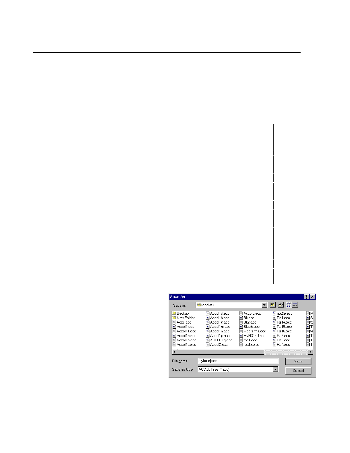
Appendix A
Creating A Sample ACCOL Load
Type in a value of ‘0’ on the ZERO terminal. This represents the 0% output for the flow
control valve.
Type in a value of ‘100’ on the SPAN terminal. This represents the 100% output for the
flow control valve.
The completed ACCOL task shoul d appear as follows:
*TASK 1 RATE: 0.200000 PRI: 1
10 * ANIN
20 * LEAD/LAG
30 * PID3TERM
40 * ANOUT
DEVICE 2
INITIAL 1
INPUT 1 F101.IN.NL
ZERO 1 F101.ZERO.
SPAN 1 F101.SPAN.
INPUT F101.IN.NL
DERIVATIVE ;ANALOG_SIGNAL_OR_VALUE
INTEGRAL F101.LAG.
RESET ;LOGICAL_SIGNAL
OUTPUT F101.IN.
INPUT F101.IN.
SETPOINT F101.SET.
DEADBAND ;ANALOG_SIGNAL_OR_VALUE
PROPORTION F101.P.
INTEGRAL F101.I.
DERIVATIVE F101.D.
RESET F101.RESET.
TRACK F101.TRACK.
OUTPUT F101.OUT.
ERROR ;ANALOG_SIGNAL
DEVICE 1
INITIAL 1
OUTPUT 1 F101.OUT.
ZERO 1 0
SPAN 1 100
TRACK 1 F101.TRACK.
RESET 1 F101.RESET.
Step 8.
Save the ACCOL source file. Click on
“File”
in the menu bar, and
“Save As”
in the pull down menu. Enter a file
name in the
“File Name”
field (in this
case we used the name ‘myload’) and
click on the
push button. Your
[OK]
edits will be saved in a file with the
extension (.ACC).
Step 9. Issue a ‘Build’ command, i f errors are presen t, correct them an d repeat step
An Introduction to ACCOL Page A-15
Page 80

Appendix A
Creating A Sample ACCOL Load
9.
Now that you’ve completed your ACCOL source file, you can translate it into an ACCOL
load file, which can be downloaded into your controller. To do this, click on
the menu bar, and
commence, and its progress will be displayed on the screen.
If a window appears with the
messages ‘Compilation Successful’
and ‘Link Successful’, you’re done.
An ACCOL Load file has been
generated.
“Build”
in the pull down menu. The load file generation will
“Actions”
in
If, instead, error messages appear, you must correct them.
In some cases, you can
simply double-click on
the error, and the
window will display the
location in the file
which caused the error.
You can edit the file
right in the window,
then save the changes,
and re-issue the build
command.
For more information on correcting errors, see the
(document# D4051).
When all errors h ave been corrected, and a su ccessfu l bu ild ha s been comp leted , you will
have an ACCOL Load file.
ACCOL Workbench User Manual
Page A-16 An Introduction to ACCOL
Page 81

Appendix A
Creating A Sample ACCOL Load
IMPORTANT
Even though you now have a downloadable ACCOL load
file, You must ALWAYS keep a copy of your current
ACCOL source file (.ACC). The ACC file will be necessary
should you ever want to change data in the running
ACCOL load. It is strongly recommended th at you keep a
backup copy of your ACC file on diskette.
Step 10. Down load the ACCOL load file into the controller.
If Open BSI Utilities is running, the Downloader utility can be activated from within
ACCOL Workbench, and the load file can be downloaded into the controller. For
instructions on downloading, see the
ACCOL II Reference Manual
the
Open BSI Utilities Manual
(document# D4044).
(document# D5081) and
WARNING
Before attempting to perfor m a down load, make sure that the
controller is ‘isolated’ from the running process, either by
disconnecting I/O, using manual backup systems, etc. An
untested ACCOL load should never be downloaded if the
controller is already controlling a process. Failure to follow
these precautions could result in injury to personnel or
damage to process equipment.
An Introduction to ACCOL Page A-17
Page 82

BLANK PAGE
Page 83

Appendix B
Working with Floating Point Numbers
All digital computers represent numbers as a series of 0’s and 1’s. Each ’0’ or ’1’ is
referred to as a ’bit’. ACCOL analog (floatin g point) si gnals in Bristol Babcock’s Network
3000-series controllers use 32 such bits, and these bits are organized according to the
single-preci sion IEEE floating point standard.
This industry standard provides compatibility and the necessary degree of accuracy for
most applications.
When single-precision floating point numbers are added, however, the smaller number
will lose precision if the difference between the exponent of the most significant digit of
the larger number of the expression, and the exponent of the least significant digit in the
smaller number of the expression, is greater than 7. Here are some examples to clarify
this rule:
Say a metering station is recording accumulated flow totals in an analog signal. The
current total number of gallons is 623.71. A new reading of 12.274 gallons is to be added
to the total.
The most significant digit in the larger number is the 6 in 623.71. Shown in exponential
notatio n it is 6 * 102. Similarly the least significant digit in the smaller number is the 4
in 12.274 or 4 * 10-3. The difference between the exponents is 5, i.e. 2 - (-3) = 5. Si nce this
is not greater than 7, there is no loss of precision, and the result is 635.984.
As a second example, say we have a station accumulating the amount of natural gas
flowing in a pipeline. The accumulated total for the month is 8,384,983.0 cubic feet. An
additional 25.443 cubic feet must be added to the total.
The most significant digit in the larger number is the leftmost 8 in 8,384,983.0. Shown in
exponential notation it is 8 * 106. The least significant digit in the smaller number is the
3 in 25.443 or 3 * 10-3. The difference between the exponents is 9, i.e. 6 - (-3) = 9. Since
this is greater than 7, the smaller number will lose some precision, and will be added as
25.375, causing the result to be 8,385,008.375.
The loss of the smaller number’s least significant digits is unavoidable under the IEEE
single precision floating point standard. When the smaller number is scaled, bits 'drop
off the end' of the scaled result.
If the magnitude of the larger number exceeds that of the smaller number by 16,777,216
then the smaller number
accumulation at all. So adding 1.0 to 16,777,216 will fail, as will adding 2 to 33,554,432,
or 0.25 to 4,194,304.
will be zero
after scaling, and it will not add to the
This problem is inherent in any computer using this format to represent numbers, from
An Introduction to ACCOL Page B-1
Page 84

Appendix B
Working with Floating Point Numbers
your hand-held calculator, to a large mainframe system.
For most applications, however, this is not a major concern, since many instruments
cannot support such precise measurements, and many industrial applications frequently
do not require such precision.
Work-Arounds For This Situation
Don’t Accumulate Totals Indefinitely
One way to prevent thi s kind of situation is to limit the size of accumulations.
If, for example, you are performing accumulations which can get large, and add small
incremen ts to i t, sa y, an eq u ip men t ru nti me me asu re men t us in g th e C omman d Mod ul e’s
RUNTIME termi nal , you migh t wan t to ‘zero out’ the runtime every month, after saving
the monthly total in a signal which can be used later as part of a yearly runtime
accumulation.
Use Double-Precision Modules, Where Necessary
Another way to lessen the impact of these problems is to use modules which support
double-precision calculations. Double-precision calculations allow many more bits for
representing numbers, internally. Note, however, that they too can eventually run out of
space for displaying full precision - - it just takes much longer to run out.
Among the modules which support double-precision internal calculations are the
Averager, ETOT/TRND, TOT/TRND, and EIntegrator. The output of these modules is
still
a single-precision value, but it is based on the more accurate double-precision
internal calculations.
The Daccumulator also allows double-precision operations, but its output is two single-
precision numbers which, when combined, provide an approximation of a doubleprecision number. See the Daccumulator section of the
(document# D4044) for details.
If you have more questions concerning these subjects, contact Bristol Babcock
Application Support for help.
ACCOL II Reference Manual
Page B-2 An Introduction to ACCOL
Page 85

Glossary
ACCOL is an acronym for Advanced Communications and
Control-Oriented Language. It is the standard software
programming language for Bristol Babcock Network
3000-series controllers.
AccolCAD is a software package, available from Bristol Babcock,
which allows an ACCOL source file to be created using
graphical sy mbols.
ACCOL Load also known as the .ACL file, is created from an ACCOL
Object file. It is call ed the ACCOL Load file becau se it is
in a machine-readable format which is downloaded into
the Network 3000-series controller. Once downloaded, the
controller executes instruction s in the ACCOL load file in
order to measure or control a plant or process.
ACCOL Object File also known as the .ACO file, is created from an ACCOL
source file. The ACO fi le i s used b y ACCOL Workbe nch to
generate an ACCOL Load fi le.
ACCOL Source File also known as the .ACC file, is created by the ACCOL
programmer using ACCOL Workbench, AccolCAD, or by
using any ASCII text editor. The ACCOL source file
defines the modules, task, signals, and other ACCOL
structures which define the measurement and control
instructions for this particular application. The ACCOL
source file, when fi nished, is used to generate an ACCOL
Object file, and ACCOL Loa d file.
ACCOL Task(s) is a series of modules and control statements which
execute sequentially as a functional block. Task execu tion
occurs at a user-sp ecified rate and priority .
ACCOL Tools is a set of software programs which includes ACCOL
Workbench, ValScan, and DIAG6.
ACCOL Workbench is a Windows-ba sed software program which allows you to
create an ACCOL source file, and to build an ACCOL
object file, and ACCOL load file from it.
Alarm Limit is a number, associated with an analog alarm signal,
which determines (in combination with a deadband value)
when the signal is in an alarm state.
G-1
Page 86

Alarm Message is a commun ications mess age, genera ted when a n analog
or logical signal enters an alarm state. Alarm messages
are passed up through the network to MMI software at
the operator workstation, to notify the operator that an
alarm condition exists.
Alarm Priority is a user-defined classification for the importance of a
given alarm signal. ‘Critical’ is the most important alarm
priority, followed in descending order of importance, by
‘Non-Critical’, ‘Operator Guide’, and ‘Event’ alarms.
ASCII is an acronym for American Standard Code for
Information Interchange. This refers to characters of text.
Base Memory is a term which applies to 186-based and 386EX Real
Mode controllers only. Each of these types of units has
64K of base memory which holds most ACCOL structures.
386EX Protected Mode units do NOT use the term ‘base
memory’.
Bit A value of ‘0’ (OFF) or ‘1’ (ON). Bits are used to represent
information in computers.
BSAP Bristol Synchronous Asynch ronous Protocol.
Byte A group of 8 bits.
Character string A collection of alpha numeric information. For example
“PUMP NUMBER 4” is a string of 13 characters (which
includes spaces.)
Cold Start is a condition in which the Network 3000 controller has
lost all accumulated data, either because of a watchdog
failure, or because the operator has pressed the unit’s
reset button. Upon cold start, the unit will wait for a new
ACCOL load to be downloaded, unless one already has
been stored in EPROM or FLASH memory.
Communication Ports these are devices on the Network 3000 controller, which
allow the controller to exchange data with other
controllers and d evices.
Control Statement(s) these are statements which may be included in an
ACCOL Task to modify the execution of the task.
Common control statements include SUSPEND,
RESUME, ABORT, IF, ENDIF, etc.
G-2
Page 87

Data Array(s) these are tables of values. Arrays can contain either
logical values (1 for ON, 0 for OFF), or floating point
analog values.
Data Concentrator This is a Network 3000 controller which has a Master
Port, through which it accepts data from one or more
slave controllers. Data concentrators are typically used
when ACCOL control decisions must be made based on
data from more tha n one controller.
Deadband this is a value used to provide a range, above or below an
alarm limit, (or RBE value, in the ca se of RBE signals) in
which the alarm state (or RBE report status) will not
change.
DIAG6 is one of the ACCOL Tools. It is also called the 33XX
Diagnosti cs Program. It is u sed to test certain pa rts of th e
Network 3000 controller hardware.
Download is the process of transferrin g an ACCOL load file into the
memory of a Network 3000-series controller. Downloading
is performed using the Open BSI Downloader.
DPC Distributed Process Controller. See Remote Process
Controllers
EPROM Erasable Programmable Read-Only Memory.
Expanded Memory is extra memory, beyond the base memory, which is
installed in a 186 or 386EX Real Mode controller. This
memory is used to hold certain selected ACCOL
structures which may be shifted out of base memory, to
free up space in the base memory area. In addition, there
are certain structures which can only exist in expanded
memory. The term expanded memory does NOT ap ply to
386EX Protected Mode controllers.
FLASH is a type of memory used in some types of Network 3000
controllers which allows an ACCOL load file (but not
data) to be retained even after a cold start condition.
Human-Machine
Interface (HMI) this is a software package, such as OpenEnterprise,
Intellution® FIX®, or Iconics Genesis, which is used to
display and report data for an operator.
G-3
Page 88

LocalView is an Open BSI utility which allows local communication
with a controller. It also allows the user to p erform field
upgrades of controller firmware for certain controller
models.
Memory is the part of the Network 3000 controller which holds the
ACCOL load file, and accumulated data.
Module are pre-programmed structures which are used to perform
mathematical, communication, and process control
functions in ACCOL. Modules are inserted into ACCOL
tasks in a logical order, and are connected together using
signals.
Module Terminal(s) are used to specify the inputs, or outputs of a module.
Signals (or in some cases, constant va lues) are entered on
module terminal s. By entering th e same signal name on
two different terminals, those terminals are said to be
‘wired’ together.
NETBC5 is one of the ACCOL Tools. It is also called the Network
Batch Compiler. This program takes an ASCII file and
uses it to generate the Network file NETFILE.DAT.
NOTE: Open BSI 3.0 or newer users MUST use NetView
instead.
NETREV5 is one of the ACCOL Tools. It is also called the Network
Reverse Compiler. This program take s the NETFILE.DAT
file, and converts it into an editable ASCII file. NOTE:
Open BSI 3.0 or newer users MUST use NetView instead.
NETTOP5 is one of the ACCOL Tools - - also known as the Network
Topology Program. It allows the user to define the
structure of the controller network including network
levels, addresses, etc. The NETTOP files containing this
information are NETFILE.DAT, GLADXREF.DAT, and
RTUXREF.DAT. NOTE: Open BSI 3.0 or newer users
MUST use NetView instead.
NetView a program in Open BSI used to define your
communication network, and to start communications.
See the Open BSI Utilities Manual (document# D5081)
for details.
Network 3000 a product name for a family of Bristol Babcock digital
remote process controllers and related equipment.
G-4
Page 89

Node a Network 3000 controller which is part of a network of
controllers.
Open Bristol
System Interface see Open BSI
Open BSI stands for Open Bristol System Interface. Open BSI is a
set of software utility programs which facilitate data
collection and communications with a network of Bristol
Babcock Network 3000-series controllers. The utilities in
the standard Open BSI set include NetView, LocalView,
DataView, and the Downloader.
Points these are input/output (I/O) connections on a process I/O
board.
Pre-emptive
Multi-Tasking a method in which multiple ACCOL tasks execute
concurrently, however, those with higher priority are
always executed first.
Process I/O the input/output (I/O) data from a process or plant. This
data comes from devices such as meters, pressure
switches, tempera ture tran smitters, etc. Thi s typ e o f d ata
comes into the controller through Process I/ O boards.
Process I/O boards these are hardware devices, installed in slots in the
Network 3000 controller, which are used to send and
receive process I/O data. See Process I/O.
RAM Rand om Access Memory. Th is i s memory th at can b e both
read from, and written to.
Read-only this is data in memory which is fixed; i.e. it cannot be
changed by an operator on-line.
Read Priority this is the security level, required by an operator or
program, to read signal data.
Read/Write this is data in memory which can be either read, or
changed.
Redundant this refers to a configuration in which two Network 3000
controllers are linked together in a way in which one can
assume the duties of the other, if the other controller
fails.
G-5
Page 90

Remote Process
Controllers also known simply as ‘remotes’. These are essentially a
type of computer which is used to measure or control a
process. (Typical examples of processes include
controlling flow in a natural gas pipeline, measuring
liquid level in a tank, or controlling a factory production
line.) Bristol Babcock’s Network 3000 series of remote
process controllers includes the DPC 3330, DPC 3335,
RTU 3305, RTU 3310, etc. These units collect data,
perform calculations, and issue control commands to the
process. The term ‘remote’ is sometimes used to refer to
controllers because they are often installed at locations
that are physically distant from the operator workstation.
Other synonymous terms include ‘RTU’ or ‘DPC', or
'33XX'. See also Node.
RTU Remote Terminal Unit. See Remote Process Controllers
Signal is a software structure which is used to pass data from
module to module in an ACCOL load . They are similar to
‘variables’ or ‘tags’ in other programming languages. The
ACCOL programmer enters a signal name on a module
terminal . By pl acing th e same si gnal n ame on a termin al
of a different module, the modules are said to be ‘wired’
together , and data ca n pass betwee n them; i.e. th e value
of a signal on an output terminal of one module becomes
an input to another module, and so on. There are five
types of signals in ACCOL: Logical, Logical Alarm,
Analog, Analog Alarm, and String.
Signal List a signal list is a way to group signals together. Signals
are referenced by their position in the list. Several
ACCOL modules are available for referencing signal lists.
Supervisory Control
and
Data Acquisition
(SCADA) is a method of process control in which a supervisory
computer, typically running MMI software, collects data
from a network of remote process controllers, displays the
data for an operator, and allows the operator to issue
commands which are sent out to control the process.
System Signals these are special ACCOL signal s (di stingu ished by a ‘#’ as
the first character in the signal base name) which are
created by the system for various housekeeping purposes.
G-6
Page 91

They may be used by the ACCOL programmer, but cannot
be created or deleted by the ACCOL programmer.
Task see ACCOL Task(s)
Task Control
Statements see Control Statements
Task Priority is a value, assigned by the ACCOL programmer, to each
ACCOL Task. This value i s used to determine which task
should execute next. Priorities can range from 1 to 64.
Tasks which perform important calculations should be
given higher priorities.
Task Rate specif ies how often an ACCOL task is sched uled to begin
execution. If a particular task has a task rate of 1 second,
for example, then it will begin executing every second. If a
task cannot complete execution prior to its next scheduled
execution, its execution will be delayed until the previous
execution has completed; this situation is called ‘slippage’,
and indicates that the task rate has been set too fast.
Terminals see Module terminals
Top Level Node(s) a Network 3000 controller in a BSAP network, which is
on the network level immediately below the operator
workstation running Open BSI. Also known as a ‘first
level node’ or ‘first level slave’.
Warm Start if a Network 3000 controller suffers a power failure, and
power is restored prior to failure of the backup battery,
the ACCOL load will resume execution from the point
where it lost power.
Watchdog a failure condition, indicated by the Watchdog (WDOG)
LED on the controller. A Network 3000 controller in a
watchdog state must be reset, and possibly re-downloaded
in order to function again.
Word A unit of measu rement repr esenting two bytes of memory.
Write Priority this is the security level, required by an operator or
program, to chang e signa l data.
G-7
Page 92

BLANK PAGE
Page 93

READER RESPONSE FORM
Please help us make our documentation more useful to you! If you have a
complaint, a suggestion, or a correction regarding this manual, please tell us by
mailing this page with your comments. It’s the only way we know we’re doing our
job by giving you correct, complete, and useful documentation.
DOCUMENT NUMBER: D4056
TITLE: An Introduction to ACCOL
ISSUE DATE: January, 2001
COMMENT/COMPLAINT:
______________________________________________________________________________
______________________________________________________________________________
______________________________________________________________________________
______________________________________________________________________________
______________________________________________________________________________
______________________________________________________________________________
______________________________________________________________________________
______________________________________________________________________________
______________________________________________________________________________
______________________________________________________________________________
______________________________________________________________________________
______________________________________________________________________________
______________________________________________________________________________
Mail or FAX this page to:
Bristol Babcock Inc.
1100 Buckingham Str eet
Watertown, CT 06795
FAX#: (860) 945-2213
Attn: Technical P ublic ations Gr oup, Dept. 610 RRF - 1/2001
Page 94

&VMWXSP&EFGSGO-RG
an FKI company
1100 Buckingham Str eet
Watertown, CT 06795
Telephone: (860) 945-2200
 Loading...