

Page 1
REMOTE AUDIO
The BOOM BOXv2 is the latest refinement to Remote Audio's
popular talkback system for boom operators. This version adds
a number of features, including overall headphone level control
for the boom-op, balanced line or stereo headphone level input,
balanced line-level talkback mic output, battery status indicator
LED, TA5 connector for Remote Audio headphones with
Talkback, and support for dynamic or electret talkback
microphones.
Connecting the BOOM BOXv2:
The BOOM BOXv2 can be used with most common headsets
having an XLR mic connector and a 1/4" or 1/8" headphone
connector. It can also be connected directly to Remote Audio's
Headsets using a single TA5F connector.
The primary microphone (boom mic) connects to the female
XLR connector labeled "BOOM." This signal is sent directly
down the extension cable and is shielded from the talkback and
monitoring lines, ensuring the cleanest signal possible.
The BCS (Boom Cable System) extension cable plugs into the
panel-mounted Neutricon on the bottom of the BOOM BOXv2.
The other end of the extension(s) plugs into a fanout adapter
that connects to the mixer or recorder. Fanouts are available for
a variety of popular field mixers and recorders, including:
BCSMFV2: For use with Cooper 208, Cameo, and Mackie mixers. 8-pin
Neutricon male fans out to a ¼" Male TRS connector and two XLR3-M.
BCSMFV2442: For use with Sound Devices 442 mixers. 8-pin Neutricon
male fans out to two TA3 connectors, a XLR3-M connector and a 1/8" male
jack. The "Comm Mic Function" needs to be enabled in the 442 menu. The
BOOM BOXv2's input switch should be in the "Phones" position (fig 3).
BCSMFV2552: For use with Sound Devices 552 mixers. 8-pin Neutricon
male fans out to a XLR3-M connector and two 1/8" male jacks. "Talk Back
mode" needs to be enabled in the 552 menu system. The BOOM BOXv2's
input switch should be in the "Phones" position (fig 3).
BCSMFV2CL9: For use with Sound Devices 788T recorders with CL-9
controllers. 8-pin Neutricon male to two XLR3-M connectors and a TA3F.
The BOOM BOXv2's input switch should be in the "Bal. Line" position (fig 3).
BCSMFV2DEVA: For use with Zaxcom Deva recorders. 8-pin Neutricon
male fans out to two XLR3-M connectors and an XLR3-F. The BOOM
BOXv2's input switch should be in the "Bal. Line" position (fig 3).
BCSV2ADPT: For adapting original BOOM BOX mixer fans to BOOM BOX
v2 standard. 8-pin Neutricon Female to 8-pin Neutricon Female, 8".
The BCS extension cables are made with Canare 2-pair
Starquad, dedicating a noise-free Starquad pair for the boom
microphone while the second pair is used for monitoring and
communications. XLR adapters, which convert the extensions
into 2-pair Starquad snakes, may be ordered from your Remote
Audio dealer. [NOTE: This system in not compatible with extensions
made for ENG "break-away" cables. Even though they use the same 8-pin
Neutricon connectors and may seem to work at first; the wiring schemes
are different. Remote Audio boom cable extensions are labeled "BOOM",
and made only with 2-pair Starquad wire, currently Canare L4E3-2P.]
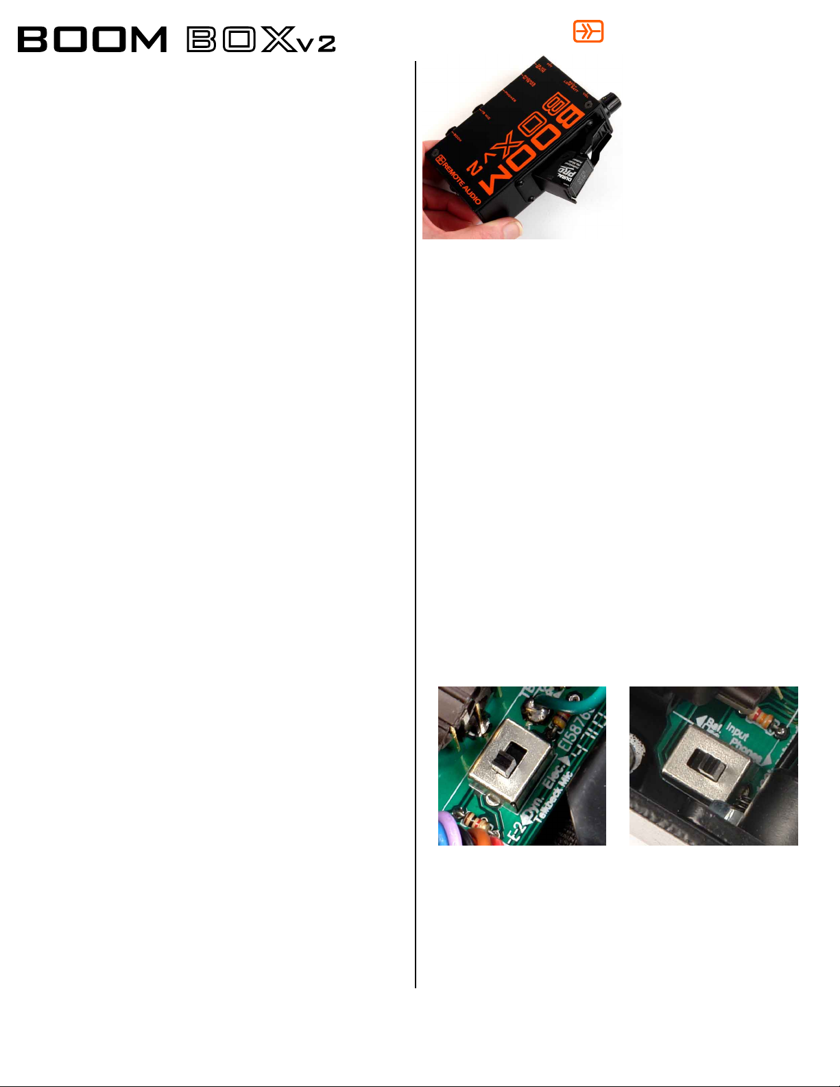
Powering the BOOM BOXv2:
The BOOM BOXv2 requires a 9V battery to power the
headphone amplifier and talkback mic preamplifier. Fold down
the 9V battery door, flip up the hinged cover (fig.1), and insert
the battery, terminals first. The battery will only fit one way. If
the hinged cover doesn't latch easily, make sure the battery is
inserted correctly.
Dimensions: 3 x 5.1 x 1.75 inches.
Weight: 10 oz
Idle current consumption: 20mA @ 9VDC
Frequency Response: 10 Hz - 25 kHz, +/- .5dB
Limited Warranty
Remote Audio warrants the BOOM BOXv2 against defects in materials and workmanship for a period of six (6) months from date of original retail purchase. This is
a non-transferable warranty that extends only to the original purchaser. Remote Audio will repair or replace qualifying products at its discretion at no charge.
Damage related to severe conditions or other abuse is not covered under this warranty.
fig.1
When the pushbutton on the top of the BOOM BOXv2 is
pressed, the signal from the talkback microphone on the boomoperator's headset is amplified and sent down the BCS
extension to the mixer as a balanced line-level signal. It is also
simultaneously mixed with the monitor signal from the mixer and
heard in the boom-operator's headphones.
The BOOM BOXv2 has an adjustable talkback output level
located on one side of the box (marked "TB MIC GAIN") and is
accessible with a small screwdriver. When shipped, it is preset
to give a comfortable level for the boom operator (about 12
o'clock) using a Remote Audio headset with electret talkback
mic. If adjustment is needed, follow this procedure: Set the
BOOM BOXv2 volume control for desired loudness of the signal
to be monitored. Without changing the volume control position,
adjust the TB MIC GAIN trim pot so that the boom operator
hears their own voice at a volume comfortable to them with the
mic placed close to the mouth. Then, adjust the input sensitivity
of the mixing console's talkback input to the desired level for the
recordist.
feedback could result.]
[NOTE: If the talkback gain is set too loud, acoustical
Talkback Mic Configuration:
The BOOM BOXv2 adds support for electret talkback
microphones through an internal switch (fig.2). The BOOM
BOXv2 is shipped with the selection switch in the "Elec."
position (indicated on the circuit board). This switch can be
accessed and changed to the "Dyn" position by removing the
two screws in the front panel and sliding the switch.
Monitor Input Configuration:
The Boom Cable System has the ability to carry a balanced linelevel signal to the boom operator, or a stereo or mono
headphone-level signal via a switch inside the BOOM BOXv2
(fig.3). By default, the BOOM BOXv2 is shipped with this switch
in the "Phones" position (indicated on the circuit board).
[Note: stereo headphone-level signals are summed to mono at the
BOOM BOXv2.]
220 Great Circle Road, Suite 114, Nashville, TN 37228-1737
Phone: 615.256.3513 | Fax: 615.259.2699
www.remoteaudio.com
Using the BOOM BOXv2:
To turn the BOOM BOXv2 on,
rotate the headphone volume
knob clockwise until it clicks
on. The LED should be
illuminated green. If the LED
is red, the battery voltage has
fallen below ~6.1V and should
probably be replaced.
fig.2
fig.3
Rev. 2/11
 Loading...