

REMKO KWK 100-4R, KWK 4R, KWK 400-4R, KWK 150-4R, KWK 250-4R Operation,technology,spare Parts
Page 1
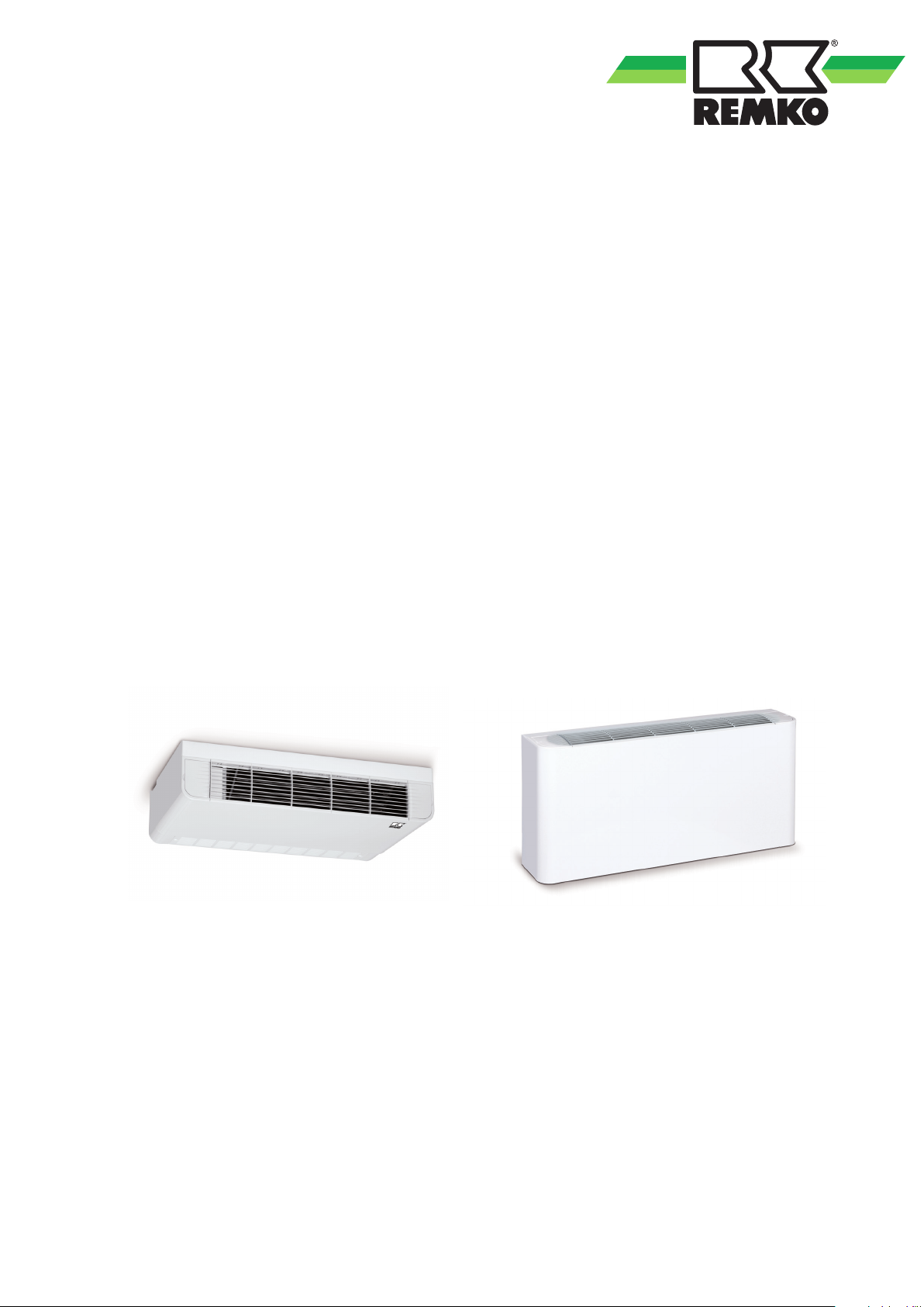
REMKO KWK -4R
KWK 100-4R, KWK 150-4R, KWK 250-4R, KWK 400-4R
Wall and ceiling chilled/hot water units for
heat pump systems
Operation · Technology · Spare parts
Edition GB – F01
Page 2

Page 3
Contents
Safety notes
Environmental protection and recycling
Transportation and packaging
Guarantee
Unit description
System layout
Operation
Shutdown
Care and maintenance
Troubleshooting and customer service
Installation Instructions for qualified
personnel
Installation
Condensate drainage connection
4
4
4
5
5
6
6-7
7
7-8
9
10-11
12-14
14
Electrical wiring
Electrical drawings
Leak testing
Before commissioning
Commissioning
Unit dimensions
Exploded view of the unit
Spare parts list
Technical data
Services
Carefully read this Operating Manual prior to commissioning/using
the units.
This operating manual is a translation of the German original.
14-15
15
15
16
16
17
17
17
18
19
These instructions are an integral part of the unit and must always be
kept in the vicinity of the installation location or on the unit itself.
Subject to modifications; no liability accepted for errors or misprints!
3
Page 4
REMKO KWK -4R
Safety notes
Carefully read this Operating
Manual before starting the unit for
the first time. It contains
useful tips and notes as well as
hazard warnings to prevent injury
to persons or material damage
. Failure to follow the directions
in this Manual can endanger
persons, the environment and the
equipment itself and will void any
claims for liability.
■
Keep this manual close to the
units.
■ The units and components
should not be exposed to any
mechanical load or extreme
levels of humidity or sunlight.
■ Only qualified personnel may
set up and install the units and
components.
■ The unit and its components
must be set-up, connected and
operated in accordance with the
use and operating conditions
stipulated in this manual and
comply with all applicable local
regulations.
■ Mobile units must be set up
securely on suitable surfaces and
in an upright position. Stationary
units must be permanently
installed for operation.
■ Modification of the units
and components supplied by
REMKO is not permitted and
can cause malfunctions.
■ Units and components may
not be operated in areas where
there is an increased risk of
damage. Observe the minimum
clearances.
■ The operational safety of
the units and components
is only assured if they are
fully assembled and used as
intended. Safety devices may
not be modified or bypassed.
■ Do not operate units or
components with obvious
defects or signs of damage.
■ All housing parts and unit
openings, e.g. air inlets and
outlets, must be free from
foreign objects, liquids, or gases.
■ The units and components must
be kept at an adequate distance
from flammable, explosive,
combustible, abrasive and dirty
areas or atmospheres.
■ Contact with some parts of the
unit or components can result in
burns or other injuries. Wearing
appropriate protective clothing
is necessary to avert risks.
■ Only authorised and trained
persons are permitted to access
and operate the units and
components.
■ Installation, repair and
maintenance work may only
be carried out by authorised
specialists. Visual inspections
and cleaning can be performed
by the operator as long as the
unit is disconnected from the
power.
■ To preclude any risks to persons
originating from the units,
appropriate precautions must
be taken when installing,
repairing, maintaining, cleaning
or working on the units.
Environmental
protection
and recycling
Disposal of packaging
All products are packed for
transport in environmentally
friendly materials. Make a valuable
contribution to reducing waste
and sustaining raw materials. Only
dispose of packaging at approved
collection points.
Disposing of the units
and their components
Only recyclable materials are used
to manufacture the units and
components.
Help protect the environment
by ensuring that the units or
components (for example
batteries) are not disposed of
in household waste, but only in
accordance with local regulations
and in an environmentally safe
manner, e.g. using authorised
disposal and recycling specialists or
council collection points.
Transportation and
packaging
The units are shipped in sturdy
transport packaging. Immediately
check the units on delivery and
make a note of any damage or
missing parts on the delivery note.
Inform the forwarding agent and
contractual partner.
Claims under guarantee made at
a later date will not be accepted.
■ The electrical power supply is to
be adapted to the requirements
of the units.
4
Page 5
Guarantee
In order to make guarantee claims,
it is essential that the ordering party
or his customer has completed
and returned the "guarantee
certificate" to REMKO GmbH &
Co. KG at the time when the unit
was purchased and commissioned.
The guarantee conditions are
listed in the "General terms
and conditions of business and
supply". Furthermore, only the
parties to a contract can conclude
special agreements beyond these
conditions. In this case, contact
your contractual partner in the first
instance.
Intended use
Unit description
In cooling mode the unit (chilled/
hot water consumer) extracts
the heat from the interior room
to be cooled into the fin heat
exchanger and releases it to the
cold operating medium (water or
a mix of water and glycol) within
a closed medium cycle. As a result
of the heat exchange, the medium
heats up and the emergent air
cools the room down.
In heating mode, a warm
operating medium warms the
room to be heated. The medium
cools down as a result of the heat
exchange.
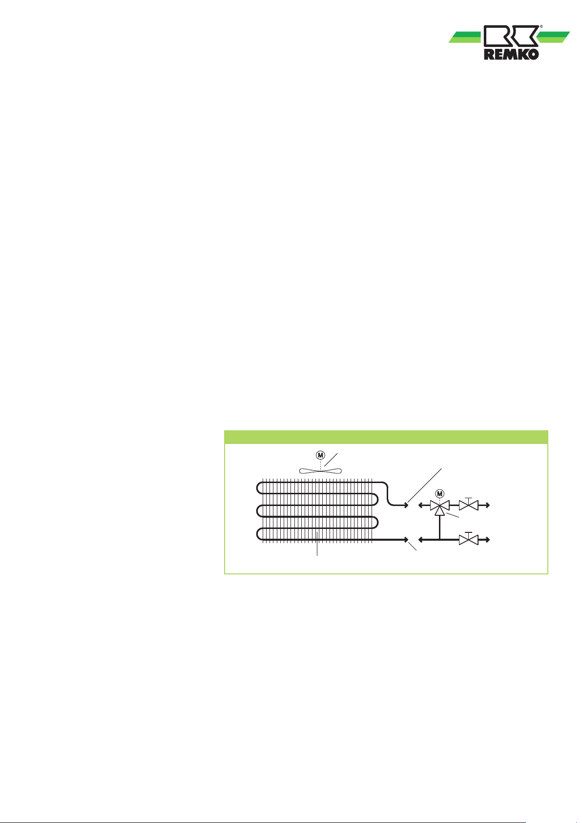
A valve assembly, which routes
the operating medium through the
register (energy is given up) or past
the resister (energy is not given
up), is used to control the cooling
or heating capacity.
The unit is designed for use
indoors in the lower wall area
(vertical installation) and for ceiling
installation (horizontal installation).
Operation is either individually
or in groups using a room
temperature controller or via the
building management system.
The unit consists of a fin heat
exchanger, circulation fan,
controller and two condensate
trays for horizontal and vertical
installation.
The available accessories include
room temperature controllers for
installation in the unit or on the
wall, fan modules, air inlet plinth
and condensate pumps.
Depending on the model and
the equipment, the units are only
intended to be used as a chilled/
hot water consumer to cool or
warm internal rooms by means
of the operating medium water
or a water-glycol mixture within
a closed medium cycle.
Any other use or use in a way
that exceeds the definition above
is considered non-intended
use. The manufacturer/supplier
assumes no liability for damages
arising from non-intended use.
The user bears the sole risk in such
cases.
Using the equipment as intended
also includes working in
accordance with the operating
manual and installation instructions
and complying with the
maintenance requirements.
Diagram of a 2-conductor system medium cycle
Recirculating fan
M
Cooling/heating heat exchanger
Connection
Medium inlet
M
Valve assembly
(Accessories)
Connection
Medium outlet
5
Page 6
REMKO KWK -4R
System layout
The unit is designed for
a 2-conductor system.
The 2-conductor system has 2
medium pipes (conductors: supply
and return flow) for cooling using
a cold medium and 2 medium
pipes for heating using a warm
medium. In cooling mode the
combined cooling / heating heat
exchanger in the indoor unit
extracts the heat from the room air
by absorbing it into the operating
medium. A circulation pump
transports the heated medium to
a chiller/warm water generator
which extracts heat from the
medium or heats the medium in
a heat exchanger. The cooled/
heated operating medium is then
fed once again to the unit in the
medium circuit.
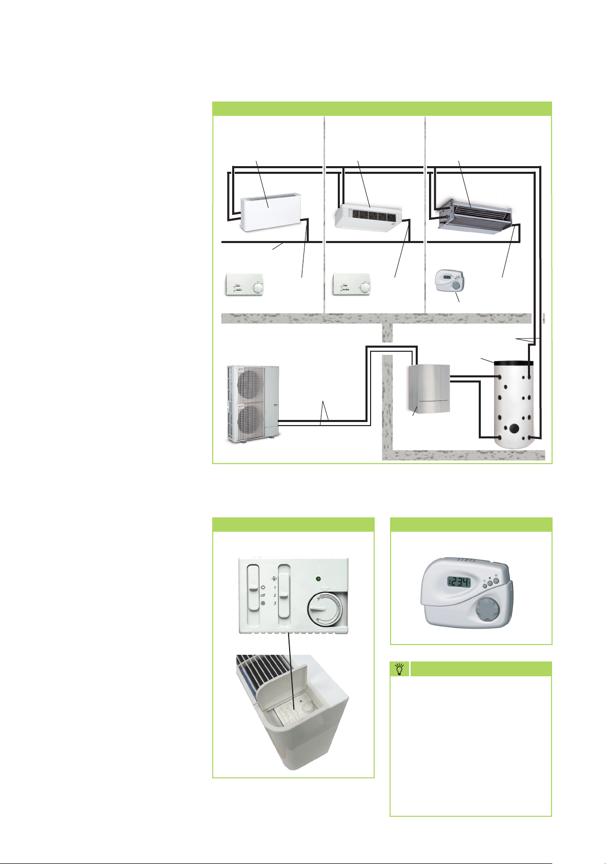
Example of system layout of 2-conductor system (heat pump system)
Indoor area 1
Chilled/heating water
Consumer
Condensate
collecting drainage
Condensate
Room temperature controller Room temperature controller Room temperature controller
Outdoor area
Inverter heat pump
Outdoor unit
Indoor area 2 Indoor area 3
Chilled/heating water
Consumer
Condensate
pipe
Refrigerant
pipes
pipe
Medium pipes
Cooling or heating mode
Chilled/heating water
Consumer
Condensate
Buffer tank
pipe
Operation
The unit can be easily operated
with the room temperature
controller available as an accessory
or a controller to be provided by
the customer. It is also possible to
activate the system using a building
management system.
Use the separate operating manuals
for this purpose.
The controller is connected to one
or more units by a cable. If a group
controller is used the maximum
current load must be observed.
Not exhaustive
Room temperature controller
Installation in the unit
Inverter heat
pump Indoor
unit
Precision room temperature controller
Wall mounting
TIP
Help by reducing energy usage
in stand-by mode! If the unit,
the system or the components
are not being used, we
recommend disconnecting the
power supply.
Our recommendation does
not apply to safety relevant
components.
6
Page 7
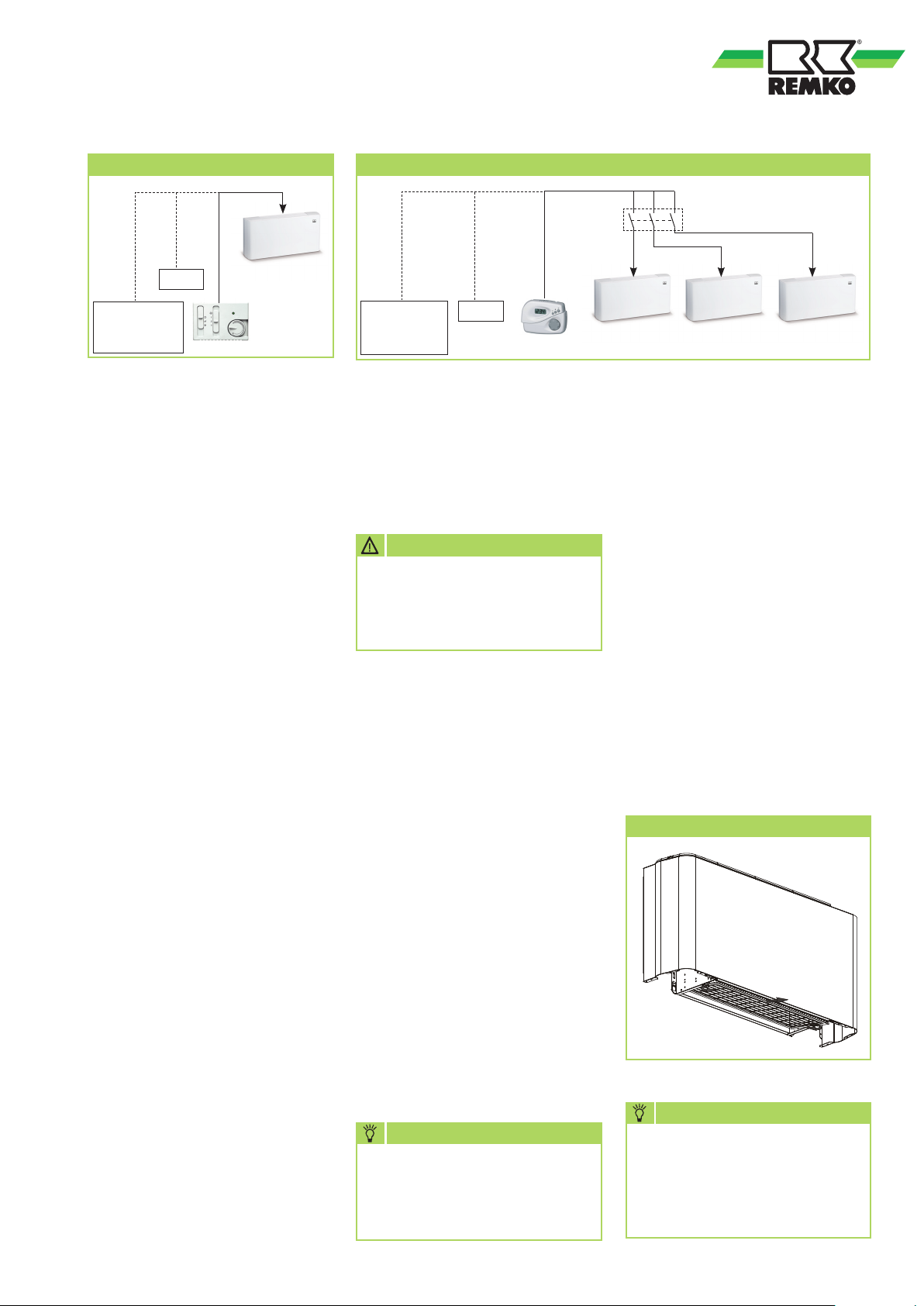
Individual control
CBCS
Group activation
Switching relay
Controller
provided by
the customer
Shutdown
Temporary shutdown
1. Let the unit run for 2 to 3
hours in circulation mode, or
in cooling mode at maximum
temperature, to extract any
residual humidity from the unit.
2. Shut down the system using the
controller.
3. Switch off the power supply to
the unit.
4. Check the unit for visible
signs of damage and clean as
described in the chapter "Care
and maintenance"
Shutdown for an indefinite
period
Ensure that units and components
are disposed of in accordance with
local regulations, e.g. through
authorised disposal and recycling
specialists or at collection points.
Controller
provided by
the customer
CBCS
Care and maintenance
Regular care and maintenance
ensure the trouble-free operation
and long service life of the unit.
CAUTION
Care and maintenance work
may only be carried out if
the unit is disconnected from
electrical power.
Care
■
Ensure the unit is protected
against dirt, mould and other
deposits.
■
Clean the unit using a damp
cloth. Do not use any caustic,
abrasive or solvent-based
cleaning products. Do not use a
jet of water.
■
Clean the fins on the unit prior
to long shutdown periods.
Maintenance
Cleaning the housing
1. Disconnect the power supply to
the unit.
2. Clean the grill and cover with
a soft, damp cloth.
3. Switch the power supply back
on.
Air filter for indoor unit
Clean the air filter at intervals of
no more than 2 weeks. Reduce this
interval if the air is especially dirty.
Filter removal
REMKO GmbH & Co. KG or your
contractual partner will be pleased
to provide a list of certified firms in
your area.
■
We recommend that you take
out a maintenance contract
with an annual service interval
with an appropriate specialist
firm.
TIP
A maintenance contract will
guarantee that your system
always operates reliably!
NOTE
In certain types of use the units
and components are subject to
a special hygiene maintenance
and inspection requirement.
7
Page 8
REMKO KWK -4R
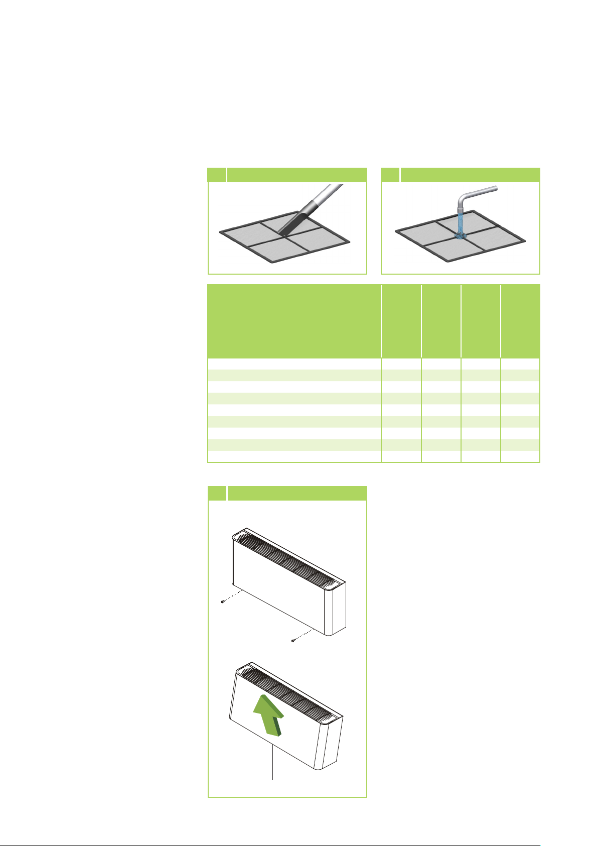
Cleaning the filter
1. Disconnect the power supply to
the unit.
2. If necessary remove the unit's
cover.
Follow the chapter "Removal
of the unit's cover".
3. Fold the filter downwards and
pull it out towards the front.
4. Clean the filter with a
commercially available vacuum
cleaner. To do this, turn the
dirty side upwards (Figure 1).
5. Dirt can also be removed
by carefully cleaning with
lukewarm water and mild
cleaning agents. Turn the dirty
side downwards to do this
(Fig. 2).
6. If water is used, let the filter dry
out properly in the air before
fitting it back into the unit.
7. Carefully insert the filter. Ensure
that it fits correctly.
1 Cleaning using a vacuum cleaner
Type of task
Checking / Servicing / Inspection
General
Medium cycle bleeding
Check medium filling
Contamination of fin register
Filter contamination
Check voltage and current
Check function of fan
Check condensate drainage
Check insulation
8. Switch the power supply and
the unit back on.
2
Cleaning with lukewarm water
Commissioning
Monthly
Half-yearly
•
• •
• •
• •
• •
• •
• •
• •
• •
Yearly
Removing the KWK-4R unit's
cover
Proceed as follows to clean the
filter of units with an air inlet plinth
or clean the fin heat exchanger:
1. Disconnect the power supply to
the unit.
2. Open the cover of the control
panel by pressing the key or
removing the screw.
3. Remove the screws under the
cover.
4. Pull the unit's cover upwards
(Fig. 3).
5. Clean the filer as described
above and re-assemble the unit
in reverse order.
3
Removing the unit's cover
KWK 100-4R-400-4R
Screw
Screw
Cleaning the condensate
pump (accessory)
The indoor unit may contain
an integrated or separate
condensate pump which pumps
any accumulated condensate into
outlets at a higher level.
Observe the care and maintenance
instructions in the separate
Operating Manual.
Cleaning the downstream
components
1. Disconnect the power supply to
the unit.
2. Clean all components such as
ducts and grills using suitable
cleaning agents including
anti-bacterial agents if
appropriate.
Unit cover
3. Switch the power supply back
on.
8
Page 9
Troubleshooting and customer service
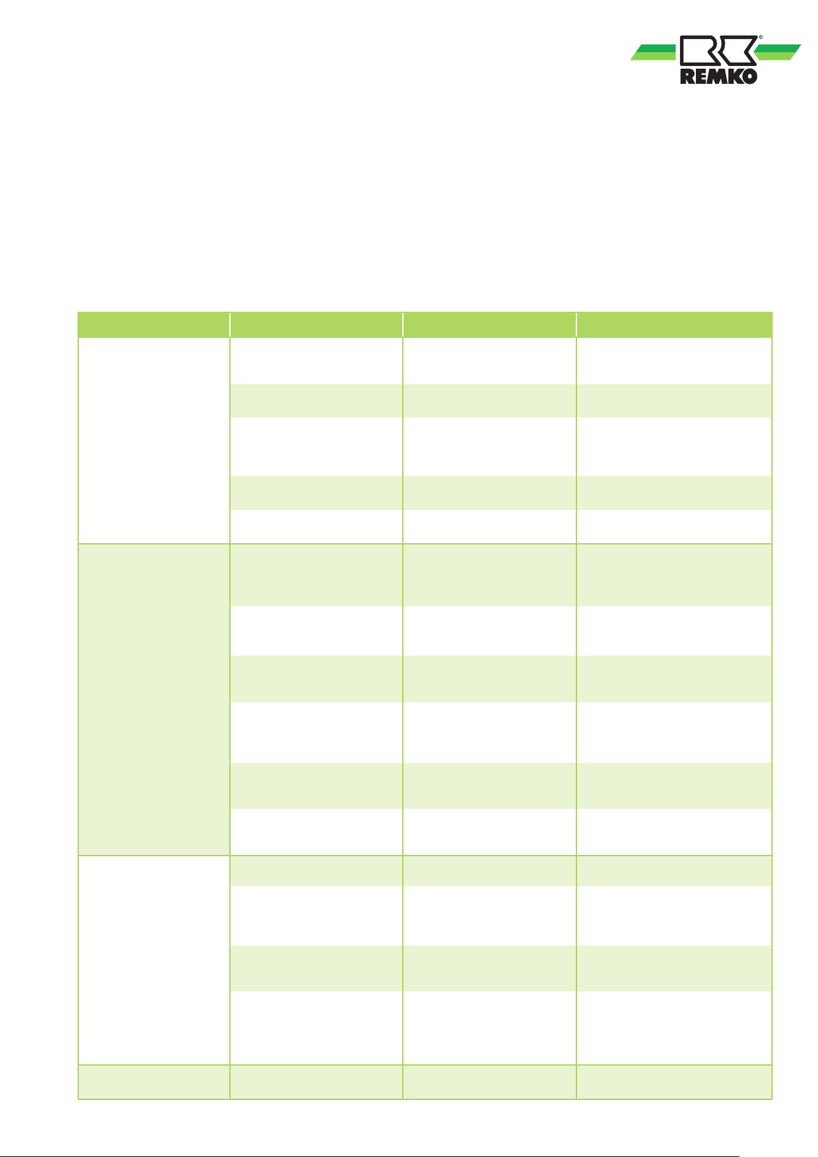
The unit and components are manufactured using state-of-the-art production methods and tested several
times to verify that they function correctly. However, if malfunctions should occur, please check the functions as
detailed in the list below. With systems for cooling or heating with indoor units, chillers or heating systems the
chapter "Troubleshooting and customer service" in all operating manuals must also be observed. Please inform
your dealer if the unit is still not working correctly after all function checks have been performed!
Operational malfunctions
Malfunction Possible cause Checks Remedial measures
The unit does not
start or switches
itself off.
Power failure, low voltage,
main fuse defective / main
switch turned off.
Power supply cable damaged.
Power surge due to
thunderstorm.
External condensate pump
malfunction.
Controller not activated
Valve assembly jammed,
not working, not yet fully
activated.
Does all other electrical
equipment function correctly?
Does all other electrical
equipment function correctly?
Have there been lightning
strikes in the area recently?
Has the pump shut down due
to a malfunction?
Has the operating mode/
controller been correctly set?
Is there any electrical power
at the valve head or has the
time period of 3 minutes after
activation passed?
Check the voltage and if necessary
wait for it to come back on.
Repair by certified service centre.
Switch off the mains breaker and
switch it back on.
Inspection by certified service
centre.
Check and clean the pump if
necessary.
Check the setting and operation.
Have the valve head replaced or
wait for time period to pass.
The unit is running but
only provides reduced
or no cooling or heating
capacity.
Condensate discharge
on unit.
Medium outlets on the
unit.
Filter is dirty / air inlet / outlet
opening is blocked by debris.
Windows and doors open.
Heating/cooling output has
increased.
Cooling mode is not set.
Medium temperature in
cooling mode too high.
Medium temperature in
heating mode too low.
Drain pipe of collector reservoir
blocked / damaged.
Insulation missing from
components carrying the
medium.
The condensate drainage line
still contains condensate.
Condensate cannot drain /
external condensate pump or
float defective.
Medium cycle / bleeding valve
leaking
Have the filters been cleaned? Clean filters.
Have structural /
usage modifications
been made?
Is the cooling symbol in the
chiller / heat pump display
activated?
Is the inlet temperature
approx. + 5 ...+ 10 °C and is
the circulation pump working?
Is the inlet temperature
approx. + 25 ...+ 45 °C and is
the circulation pump working?
Can the condensate drain off
without any obstruction?
Do all the medium-carrying
components outside the drip
area have vapour diffusion
barrier insulation?
Is there an incline on the
condensate drainage line and
is it clear?
Are the condensate drainage
lines clear and is there an
incline? Are the condensate
pump and liquid level switch
functioning correctly?
Can any leaks be seen on
components carrying medium?
Close windows and doors / install
additional systems.
Correct the settings for the unit.
Reduce the medium temperature.
Increase the medium temperature.
Clean the drainage pipe and
collection container.
Have vapour diffusion barrier
insulation properly installed.
Route the condensate drainage line
with an incline and clean it.
Route the condensate drainage line
with an incline and clean it. If the
liquid level switch or the condensate
pump is defective, have them
replaced by a specialist company.
Have leaks sealed by a specialist
company.
9
Page 10
REMKO KWK -4R
Installation instructions for qualified personnel
Important notes prior to
installation
■
Observe the Operating
Manuals for the indoor unit and
the chiller or heating system or
the heat pump system when
installing the entire system.
■
The indoor units and water
chillers and heat pump
system work independently.
A connecting line between the
two is not necessary.
■
Transport the unit in its original
packaging as close as possible
to the installation location.
You avoid transport damage by
doing so.
■
Check the contents of the
packaging for completeness
and check the unit for visible
transport damage.
Report any damage
immediately to your contractual
partner and the shipping
company.
■
Select an installation location
which allows air to flow freely
through the inlet and outlet.
(See section "Minimum
clearances").
■
Do not install the unit in the
immediate vicinity of devices
which generate intensive
radiation of heat or cold.
Installation in the vicinity of
heat or cold radiation reduces
the unit output.
■
Lift the unit at the corners
and not by the medium or
condensate connections.
■
The medium connection lines,
valves and connections must
have vapour density insulation.
If necessary, also insulate the
condensate drainage line.
In dual systems with cooling
and heating modes, the
requirements of the current
Energy Savings Ordinance
(EnEV) must be followed.
10
■
Seal off open lines to prevent
dirt getting in and never kink or
crimp the lines.
■
Avoid unnecessary bends.
This minimises the pressure loss
in the lines.
■
Make all electrical connections
in accordance with applicable
DIN and VDE standards.
■
Always ensure the electrical
cables are properly connected
to the terminals. Otherwise
there is a risk of fire.
■
Adequate clearance must be
provided to allow maintenance
access to the control box and
the valve assembly.
■
Only install the valve assembly
or other attachments once the
indoor unit has been installed.
Installation material
The indoor unit is attached using
4 bolts to be provided by the
customer.
Selecting the installation
location
Wall / ceiling unit KWK -4R
The indoor unit is designed for
vertical wall installation, for
instance underneath windows.
However, it can also be used in
the upper wall area (max. 1.25 m
above floor level).
The unit is also designed for
horizontal ceiling installation. In
this case particular attention must
be paid to the condensate drainage
(see the Chapter "Condensate
drainage connection").
Connection variants
The following connection variants
can be used for the medium and
condensate pipes and the control
lines.
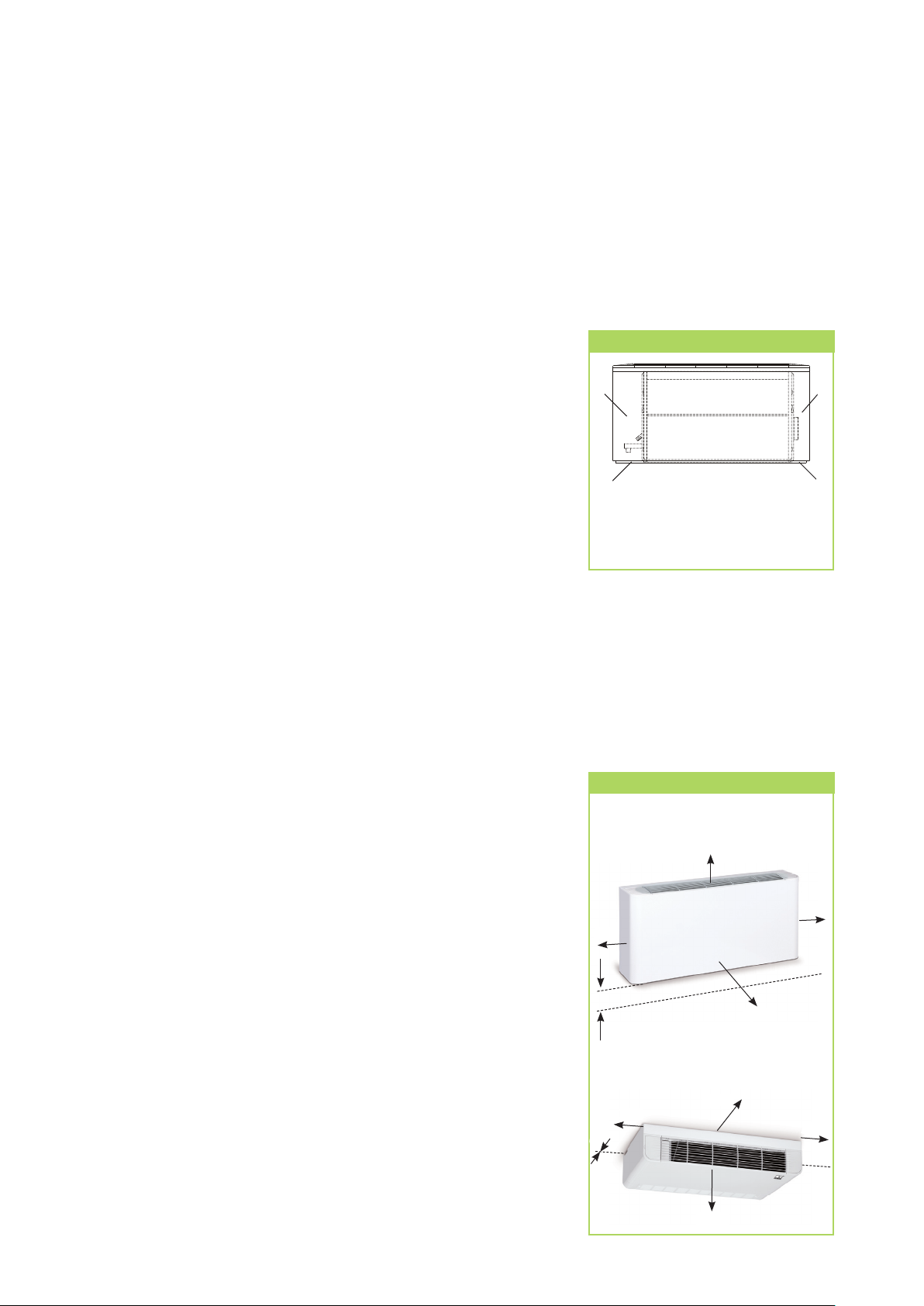
Connection variants
1
3
1 Outflow through the wall on the left
2 Outflow through the wall on the right
3 Outflow through the floor on the left
4 Outflow through the floor on the right
4
Minimum clearances
Observe the minimum clearances
to allow access for maintenance
and repair work in the suspended
ceiling and to facilitate optimum
air distribution for the cover.
Minimum clearances
KWK 100-4R to 400-4R
Wall installation with ground clearance
1,000
300
300
Min. 100
KWK 100-4R to 400-4R
Ceiling installation with air inlet plinth
300
0
1,000
1,000
1,000
300
2
Page 11
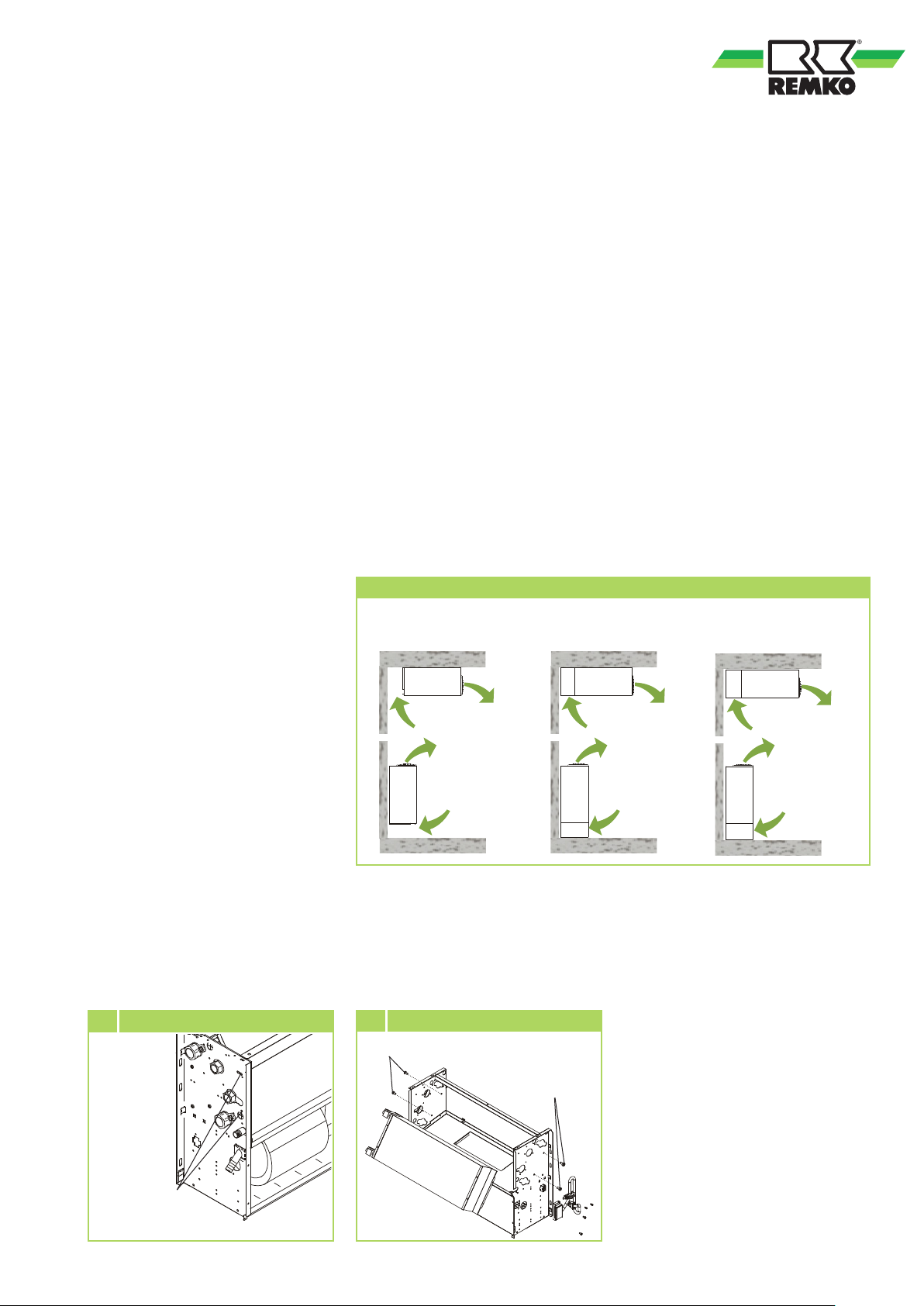
Changing medium connection parts
The connection side of the heat
exchanger and the condensate
drainage line are installed by the
works on the left-hand side of the
unit. It is possible to change this to
the right-hand side.
1. Dismantle the condensate tray
by removing the four
self-tapping screws.
2. Remove the screws from the
heat exchanger mounting on
the side cover frame (Fig. 4).
3. Pull the heat exchanger out of
the unit's mounting.
Be careful as it is easy to be cut
by the fins. Do not bend any
fins and do not damage the
insulation.
4. Cut the insulation of the side
stay plate to accommodate the
brass connections on the new
connection side.
5. Feed the connections through
the newly created holes up to
the stop (Fig. 5).
6. Place the tear-resistant
plastic film on the pipe bend
side between the stay plate
insulation and the heat
exchanger mounting. The film
protects the insulation of the
stay plate against damage.
7. Let the heat exchanger slide
into the retainer (keep the same
air duct) and after installing
the heat exchanger remove the
film and screw the unit back
together in reverse order.
Installation variants
Wall / ceiling unit KWK-4R
■ Wall mounting
The unit is secured to the wall
by the unit housing.
The air inlet is, for example,
at floor level or, for example,
via an air inlet plinth etc. The
air outlet is directly from the
housing.
■ Ceiling mounting
The unit is secured under the
ceiling by the unit housing. The
air inlet is, for example, at floor
level or, for example, via an air
inlet plinth etc. The air outlet is
directly from the housing.
Installation examples
KWK 100-4R - 400-4R
Basic unit With foot
Installing the feet /air inlet
plinth (accessory) only for the
KWK-4R
If the feet or plinth available as
accessories are be used for units
for wall and ceiling mounting,
these must be installed before the
unit is installed.
Follow the separate Installation
Instructions.
With air inlet plinth
4 Removing the condensate tray
Condensate
tray bolt
5 Removing the heat exchanger
Heat exchanger mounting bolts
Heat exchanger
mounting bolts
11
Page 12
REMKO KWK -4R
Installation
Unit installation
Selecting the hydraulic
connection
Wall installation
The unit is attached by means of
mounting holes in the case while
also taking account of the air outlet
side located in the upper part of
the unit.
■
Mark the mounting points
according to the bracket's
dimensions on structurally
acceptable building
components and secure the
unit.
■
Check again that the unit is
level.
■
Connect the medium pipes,
electrical cables and condensate
drainage line to the unit as
described below.
NOTE
Installation should only be
performed by authorised
specialists.
Unit suspension
Ceiling installation
The unit is attached by means of
mounting holes in the case while
also taking account of the air outlet
side directed towards the centre of
the room.
■
Mark the mounting points
according to the bracket's
dimensions on structurally
acceptable building
components and secure the
unit.
■
Check again that the unit is
level.
■
Connect the medium pipes,
electrical cables and condensate
drainage line to the unit as
described below.
A
B
2-conductor cooling system
■
Wall installation without valve
assembly:
When the fan is switched off
the flow of air from the air
inlet can be ignored without
sacrificing comfort. In this
application case, use of a valve
assembly is not absolutely
essential.
■
Ceiling installation without
valve assembly:
A valve assembly must be
used in this application case
to prevent the flow of cold air
from the air outlet when the
fan is switched off.
■
Wall installation with valve
assembly:
In order to prevent any flow of
cold air and severe condensate
formation, for reasons of
comfort a valve assembly can
be used in this application case.
■
Ceiling installation with valve
assembly:
In order to prevent any flow
of cold air and permanent
flow-generated noise, for
reasons of comfort a valve
assembly is recommended in
this application case.
G
CD
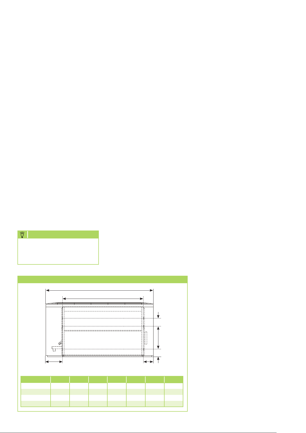
All information in mm.View from the front
A B C D E F G
KWK 100 660 415 88 158 70 205 70
KWK 150 810 565 88 158 70 205 70
KWK 250 960 715 88 158 70 205 70
KWK 400 1110 865 88 158 70 205 70
12
F
2-conductor system for
E
cooling and heating
■
As the 2-conductor system
must cool and heat equally,
for reasons of convection
during winter operation a
valve assembly is specified for
all installation methods for
this system operation to avoid
undesirable heat emission.
Page 13
Connection for
medium piping
■
The connection of the piping
by the customer is made on the
rear side of the units.
■
For the purpose of servicing,
connections must be equipped
with shut-off valves and the
medium flow rate adjusted
using hydronic balancing
valves.
■
Additional automatic bleed
valves must be provided in the
supply and return flows at the
installation's highest point.
■
The medium piping must not
exert any structural load on the
unit.
■
The pipe connections must
not impose any thermal or
mechanical stresses on the unit.
If necessary cool the piping or
support with the second tool.
System components
required
Valve assembly for 2-conductor
systems (accessory)
In 2-conductor systems, cold or
warm medium is fed through
the heat exchanger into the unit
and cold or warm air can be
discharged. Control is provided
by the 3-way valve assembly.
It consists of the electrically
actuated valve head and the valve
body. If the head is electrically
activated, it actuates the body,
which routes the medium into
the register. If the temperature is
reached, the head is switched off
and the medium is fed past the
heat exchanger through the bypass
. The bypass serves to ensure the
minimum medium flow rate for the
chiller or the heat pump.
NOTE
The time between being fully
open and fully closed can be
approx. three minutes.
Valves for hydronic balancing
The calculated individual pressure
losses in the pipeline network
layout for each individual unit are
adjusted to the entire system with
hydronic balancing valves to be
provided by the customer. The
nominal flow rates for the medium
adjust to the values needed as a
consequence of the pressure loss.
Anti-freeze protection
(accessories)
A water glycol mix is generally
used as the medium for a cold
water system. Depending on the
glycol type and quantity used, the
viscosity changes, the pressure loss
increases and the unit's cooling or
heating capacity reduces.
All system components must be
approved for use with glycol.
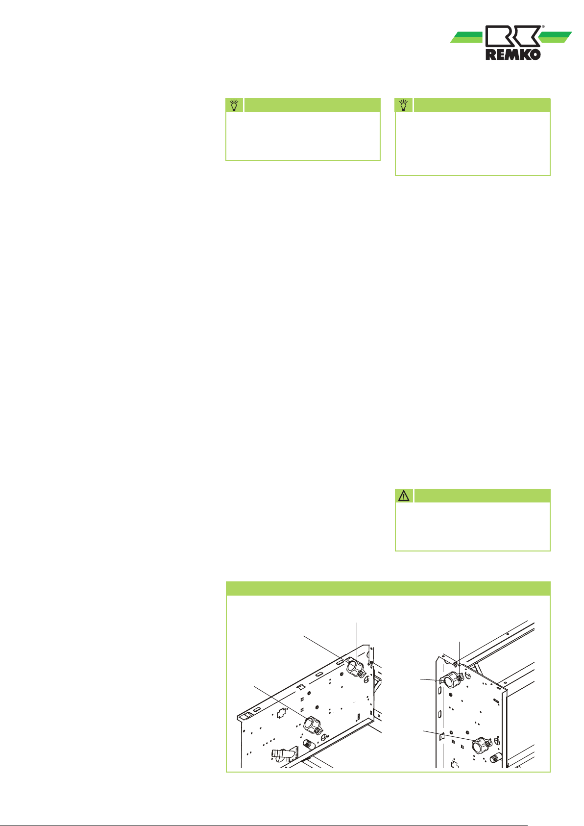
Bleeding valve
Manual bleeding
valve
Inlet
Outlet
NOTE
The product and safety data
sheets of the glycol type which
is used must be obeyed during
use and disposal.
Diaphragm expansion vessel
(MAG)
To avoid pressure fluctuations
because of temperature changes
when not operating, diaphragm
expansion vessels filled with
nitrogen (moisture neutral) must
be integrated in the system.
Automatic bleed valves
The unit has one or two manual
bleed valves on the collector pipe
of the register.
The unit can be bled separately
after the system has been filled.
Automatic bleed valves must also
be installed at the highest point in
the collector line.
CAUTION
Glycol tolerant bleeding valves
are necessary when using
media which contain glycol.
Manual bleeding
valve
Inlet
Outlet
13
Page 14
REMKO KWK -4R
Safety valve
Safety valves limit excess operating
pressure due to excess warming
or overfilling of the operating
medium. The valve outlet requires
unobstructed draining into a drain
line. Applicable local disposal
ordinances must be observed if
glycol is used.
NOTE
No moisture can condense in
the nitrogen filler.
Condensate drainage
connection
As the temperature on the heat
exchanger is below the dew point,
condensate is formed during
cooling mode.
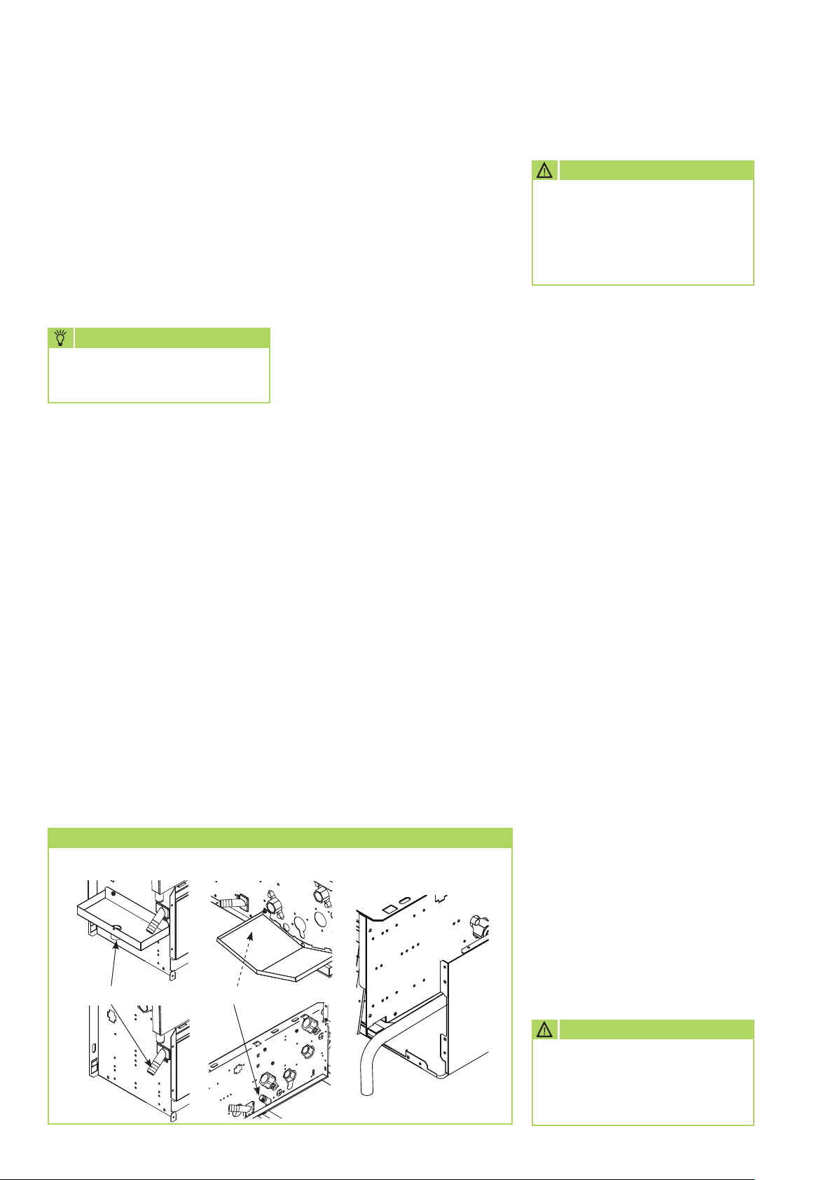
Below the heat exchanger is a
collection tray which must be
connected to a drain.
■
The condensate drainage line
provided by the customer
should be installed with an
incline of at least 2 %. If
necessary, fit vapour-diffusionproof insulation.
■
Route the condensate drainage
line of the unit into the drain
line without any obstruction.
If the condensate runs directly
into a sewer pipe, fit a trap to
prevent any unpleasant odours.
Condensate drainage connection
■
When operating the unit at
outside temperatures below
0°C, ensure the condensate
drainage line is laid in such a
manner to protect it against
frost.
If necessary, fit a pipe heater.
■
Following installation, check
that the condensate drain is
unobstructed and ensure that
the line is permanently leak
tight.
Vertical mounting
The condensate drainage line
can be connected at the funnel
nozzle. The position of the nozzle
can be selected to be on the left
or right. The condensate drainage
connection of the condensate
tray which is not used must be
permanently sealed.
If a valve assembly is used, the
connection must be made to the
additional condensate tray.
Horizontal mounting
The condensate drainage line
can be connected directly to
the condensate tray. If a valve
assembly is used, the condensate is
conveyed to the unit's pan and is
drained from there.
Electrical wiring
CAUTION
All electrical installation work
is to be performed by specialist
companies. Disconnect the
power supply when connecting
the electrical terminals.
■
We recommend installing
a master / repair switch
provided by the customer close
to the indoor unit.
■
The power supply is made to
the indoor unit; a control line
to the chiller/heat pump is not
necessary.
■
If a condensate pump, which
is available as an accessory, is
used in conjunction with the
unit, the pump switching-off
contact switches off the power
supply or the valve if necessary.
■
The terminal block for making
the connections and the plug
are located behind the unit's
cover on the right side of the
unit.
Possible accessories
Room temperature controller
■ The room temperature controller
operates the unit. The controller
can be wall-mounted or
installed in the unit, as required.
Follow the separate Installation
Instructions.
Vertical mounting Horizontal mounting Horizontal mounting
Drain duct
Condensate drainage connection Condensate drainage connection
14
Switch relay for 4 units, if appropriate
■ If several units are to be
controlled together in a group,
a switch relay is necessary if a
room temperature controller is
used.
Follow the separate Installation
Instructions.
CAUTION
The condensate drainage connection
of the condensate tray which is not
used must be permanently sealed
(a cap or similar).
Page 15
Condensate pump
■ If the condensate which forms is
to be removed by a condensate
pump, this can be placed in the
unit.
Follow the separate Installation
Instructions.
CAUTION
Check all plug and terminal
connections to verify that
they are tight and make a
permanent contact. Tighten as
required.
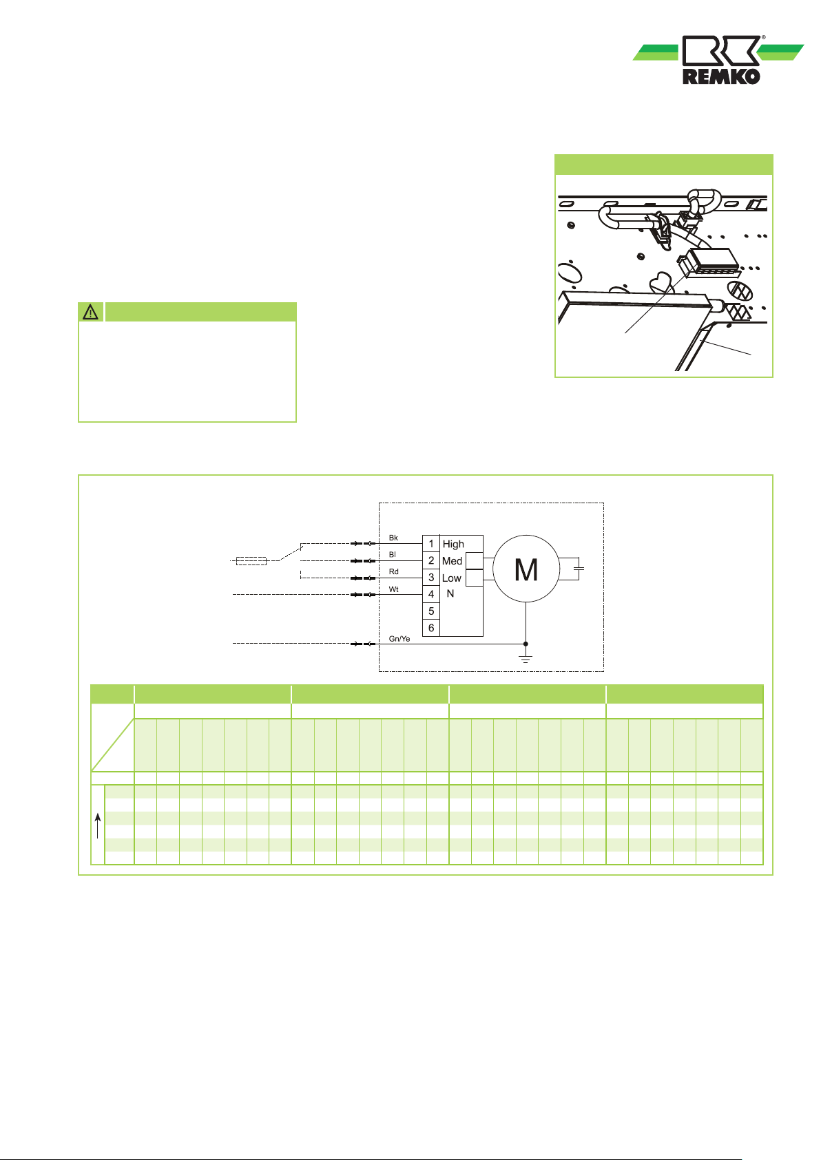
Electrical drawings
KWK 100-4R to 400-4R
Power supply
230V, 1~, 50Hz
Phase conductor
Neutral conductor
Earth conductor
Make the connection as follows:
1. Open the unit's cover.
2. Insert the cables into the unit.
3. Connect the unit with
a controller and the power
supply.
See electrical drawings.
4. Install all removed parts.
Level 3
Level 2
Level 1
Electrical wiring
Connection terminals
Legend
Wt = white
Gn = green
Ye = yellow
Pk = pink
Gn/Ye = green/yellow
Bl = blue
Bn = brown
Bk = black
Gr = grey
Vi = violet
Or = orange
Rd = red
KWK 100-4R KWK 150-4R KWK 250-4R KWK 400-4R
Conden-
sor
m³/h dB(A) dB(A)
Item 1
333 40.5 49 63 1 338 43.5 52 44 1 584 47.5 56 85 1 716 47.5 56 90 1
Item 2
296 39.5 48 56 2 348 41.5 50 38 2 505 44.5 53 75 2 570 42.5 51 69 2
Item 3
252 38.5 47 49 3 304 38.5 47 32 3 430 41.5 50 65 3 490 37.5 46 58 3
Item 4
200 34.5 43 40 4 bk 1 254 36.5 45 29 4 bk 1 353 36.5 45 54 4 bk 1 432 34.5 43 47 4 bk 1
Item 5
147 28.5 37 29 5 bl 2 194 32.5 41 21 5 bl 2 254 27.5 36 40 5 bl 2 300 26.5 35 35 5 bl 2
min max
Item 6
128 25.5 34 27 6 rd 3 184 25.5 34 17 6 rd 3 232 26.5 35 36 6 rd 3 283 25.5 34 30 6 rd 3
Air flow
1.0 µF 2.0 µF 1.5 µF 2.5 µF
level
Sound power
Sound pressure
Power
consumption
W
colour
terminal
Conductor
Transformer
Connection
Leak testing
The leak test is carried out after
the connection has been made.
1. Flush the system twice with tap
water.
2. Clean the sieve insert on the
dirt trap.
3. Fill the system with water again
and vent the unit at the manual
Air flow
Sound power
Sound pressure
m³/h dB(A) dB(A)
level
Power
W
consumption
colour
terminal
Conductor
Transformer
Connection
m³/h dB(A) dB(A)
bleed valves.
4. Adjust the test pressure to at
least 200 kPa (2.0 bar).
5. Check the connections for
leaking water after a period of
at least 24 hours . If leaks are
visible, the connection has not
been properly made. Tighten
Air flow
level
Sound power
Sound pressure
Power
Transformer
consumption
W
terminal
Conductor
colour
Connection
m³/h dB(A) dB(A)
Air flow
level
Sound power
Sound pressure
the threaded connection or
make a new connection.
6. After a successful leak test,
remove the excess pressure
from the medium piping if a
water-glycol mixture is used
or adjust the non-circulating
pressure to the required system
pressure.
Power
Transformer
consumption
W
colour
terminal
Conductor
Connection
15
Page 16

REMKO KWK -4R
Before commissioning
Anti-freeze protection for the
medium
If a water-glycol mixture is used,
it is to be pre-mixed before being
put in the system. The desired
concentration must then be
checked.
Bleeding the system
■
Air may still be in the pipe
lines after the leak test. This
is carried to the automatic
bleeding valves or the
consumer by the operation of
the circulation pump. In this
case it is necessary to bleed the
system again.
■
The non-circulating pressure
must then be adjusted to the
required system pressure.
MAG
■ The preliminary pressure for the
diaphragm expansion vessel
must be adjusted individually to
the system layout, the volume
of the medium and the
installation site.
Valves for hydronic balancing
■
The calculated excess pressure
in the pipe network layout
at the individual cold water
consumers must be adjusted at
the hydronic balancing valves.
Safety valve
■
The safety valves and their
correct function must be
checked.
Commissioning
■
Commissioning should only be
performed and documented by
specially trained personnel.
■
Observe the manuals for the
unit and all other components
when commissioning the entire
system.
Function test for cooling operating
mode
1. Switch the power supply on
and if necessary open all shutoff valves.
2. Switch on the chiller, the heat
pump and the corresponding
circulation pump. The outlet
temperature must be between
+4 and +18°C.
3. Use the controller to switch on
the unit and select the cooling
mode, maximum fan speed and
lowest target temperature.
4. Measure and record all
the required values in the
commissioning report and
check the safety functions.
5. Check the unit control system
using the functions described in
the Chapter "Operation".
6. Check that the condensate
drainage line is functioning
correctly by pouring distilled
water into the condensate tray.
Function test of heating operating
mode
1. Switch the power supply
on and if necessary open all
shut-off valves.
2. Switch on the chiller, the heat
pump and the corresponding
circulation pump. The outlet
temperature must be between
+35 and +70°C.
3. Use the controller to switch on
the unit and select the heating
mode, maximum fan speed and
highest target temperature.
4. Measure and record all
the required values in the
commissioning report and
check the safety functions.
5. Check the unit control system
using the functions described in
the Chapter "Operation".
Final tasks
■
Reassemble all disassembled
parts.
■
Familiarise the operator with
the system.
NOTE
During manual bleeding, any
glycol mixtures which escape
must be disposed of separately.
Do not feed them into the
condensate tray!
■
The drain line for the valves is
to be checked for function and
leak tightness.
16
Page 17
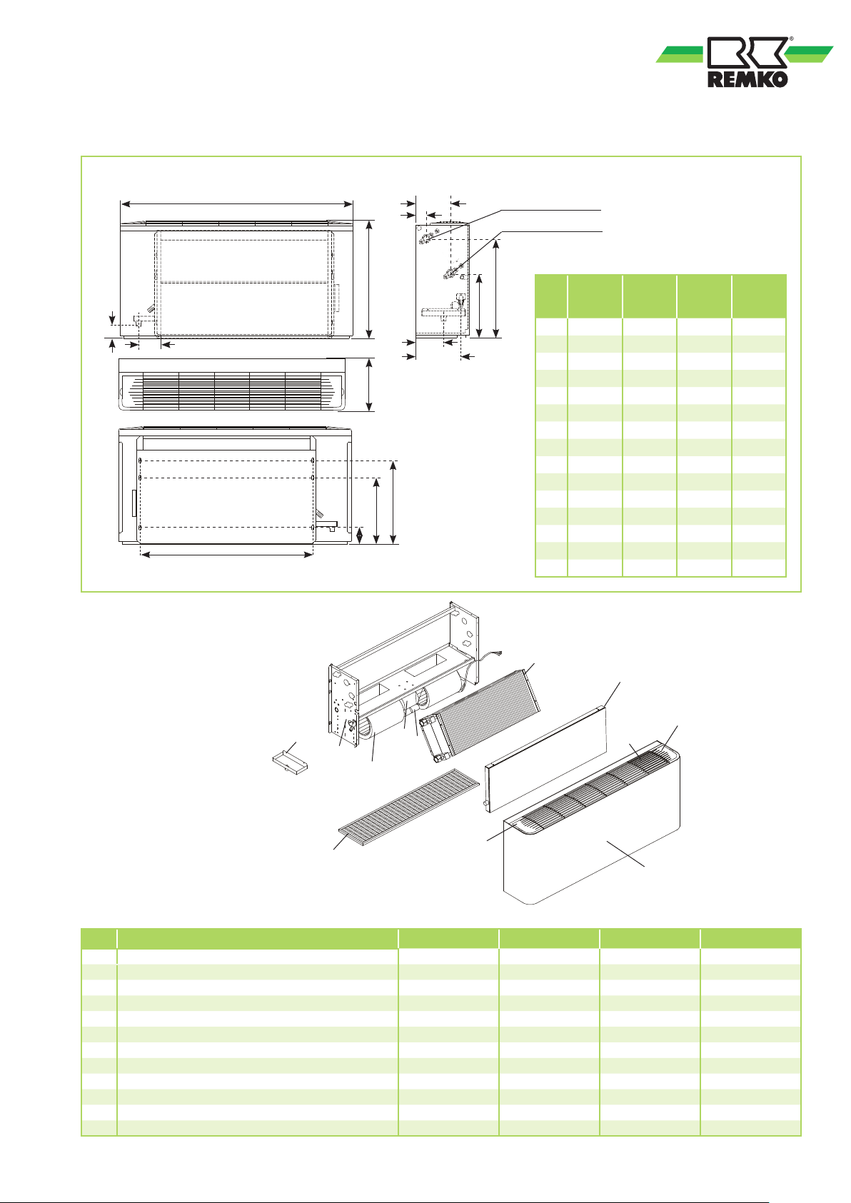
Unit dimensions
KWK 100-4R to 400-4R
A
K
J
Cooling / heating inlet
Cooling / heating outlet
D
E
L
Exploded view of the units
KWK 100-4R to 400-4R
B
H
I
C
O
N
M
All information in mm
KWK
G
F
100-
4R
A 660 810 960 1110
B 480 480 480 480
C 220 220 220 220
D 70 70 70 70
E 95 95 95 95
F 249 249 249 249
G 393 393 393 393
H 96 96 96 96
I 185 185 185 185
J 42 42 42 42
K 156 156 156 156
L 415 565 715 865
M 70 70 70 70
N 275 275 275 275
O 345 345 345 345
KWK
150-
4R
KWK
250-
4R
KWK
400-
4R
2
8
4
9
12
10
11
3
6
7
5
1
Spare parts list
No. Designation
1 Unit cover 1111750 1111751 1111752 1111753
2 Finned heat exchanger 4 rows of tubes 1111746 1111747 1111748 1111749
3 Outlet grill 1111764 1111764 1111764 1111764
4 Control panel, right 1111765 1111765 1111765 1111765
5 Control panel, left 1111766 1111766 1111766 1111766
6 Fan unit, complete. 1111767 1111768 1111769 1111770
7 Air filter 1111773 1111774 1111775 1111776
8 Condensate tray 1111779 1111780 1111781 1111782
9 Condensate tray, valve assembly, vertical 1111785 1111785 1111785 1111785
10 Transformer, speed step 1111786 1111778 1111788 1111789
11 Condenser fan 1111794 1111795 1111796 1111797
12 Condensate connection 1111790 1111790 1111790 1111790
When ordering spare parts, please state the EDP and unit number (see name plate)!
KWK 100-4R KWK 150-4R KWK 250-4R KWK 400-4R
17
Page 18
REMKO KWK -4R
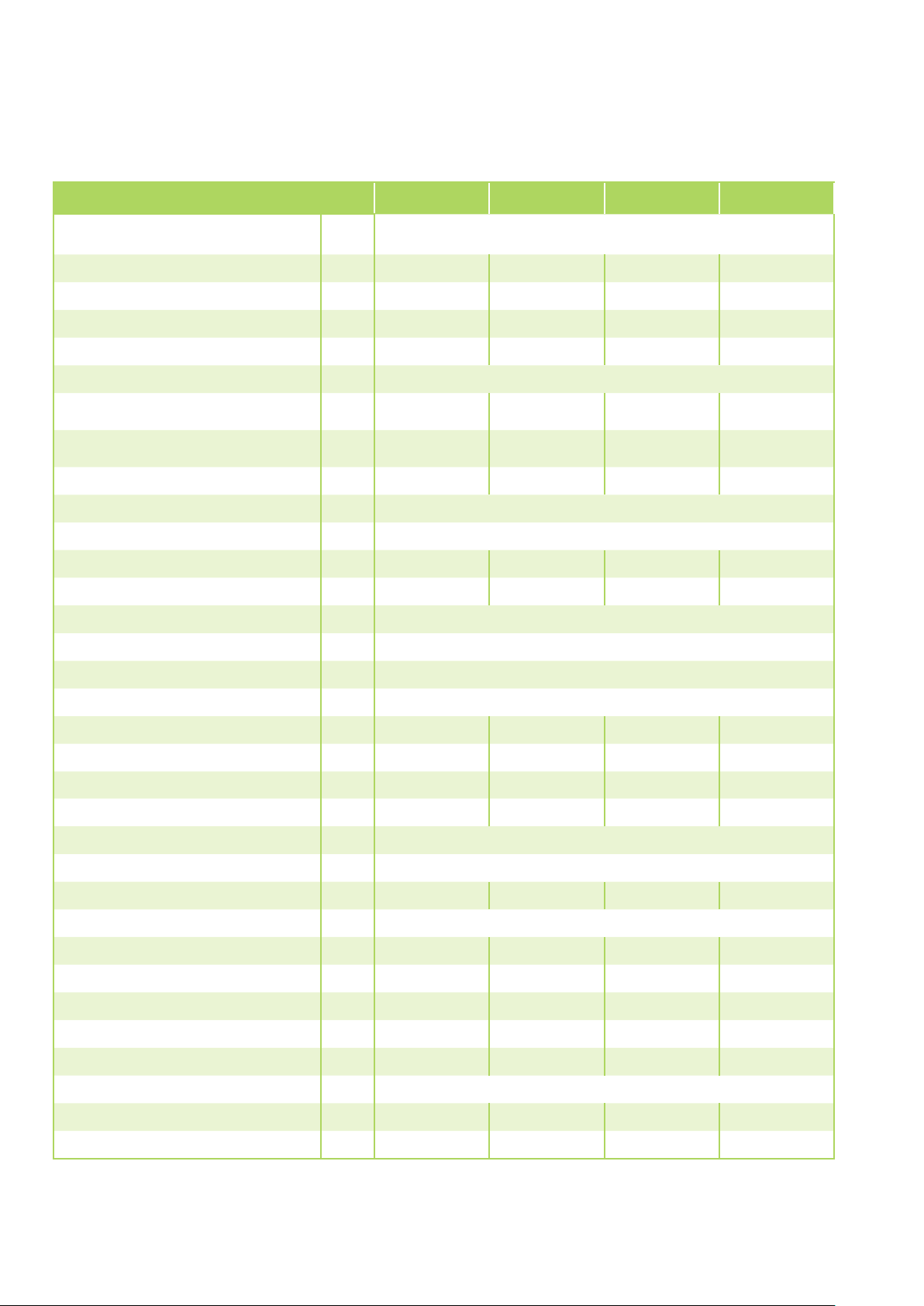
Technical data
Series KWK 100-4R KWK 150-4R KWK 250-4R KWK 400-4R
Operating mode
Nominal cooling output
Nominal cooling output, sensitive
Nominal heating capacity 2) /
1)
1)
3)
Application area (room volume), approx.
Operating range - indoor unit
Air flow volume per stage
Sound pressure level per stage
4)
Sound power level per stage
Power supply
Enclosure class
Electr. rated power consumption
Electr. rated current consumption
1)
1)
Operating medium
Operating limits, medium - cooling
Operating limits, medium - heating
Chilled/hot water units for wall and ceiling mounting, 2-conductor version
kW
kW
kW
1.18 1.59 2.21 2.73
0.93 1.23 1.70 2.08
1.35 / 0.66 1.80 / 0.97 2.53 / 1.40 3.05 / 1.68
m³ 45 60 80 100
°C +15 to +35
m³/h 128/147/200 184/194/254 232/254/353 283/300/423
dB(A) 25.5/28.5/34.5 25.5/32.5/36.5 26.5/27.5/36.5 25.5/26.5/34.5
dB(A) 34/37/43 34/41/45 35/36/45 34/35/43
V/Hz 230/1~/50
IP X0
kW 0.04 0.03 0.05 0.05
A 0.19 0.15 0.26 0.31
Water; max. 35 % ethylene-glycol, max. propylene-glycol max. 35 %
°C +4 to +18
°C +35 to +80
Max. operating pressure, medium
kPa 600
Nominal flow rate, medium - cooling 1)/ 3)m³/h 0.20 0.27 0.38 0.47
Nominal flow rate, medium - heating
Rated pressure drop, internal - cooling
Rated pressure drop, internal - heating
Medium connection, inlet
Medium connection, outlet
Medium volume
Condensate drainage connection
2)
m³/h 0.24 / 0.11 0.31 / 0.17 0.44 / 0.24 0.53 / 0.29
1)
kPa 1.2 3.3 6.7 5.5
2)
kPa 2.1 / 0.6 4.6 / 1.6 10.7 / 4.0 7.8 / 2.9
Inches 1/2 female
Inches 1/2 female
l 0.9 1.2 1.5 2.2
mm 19
Dimensions - Height mm 480 480 480 480
Width mm 660 810 960 1110
Depth mm 220 220 220 220
Weight
Operating weight, approx.
Standard colour
Serial number
EDP no.
kg 14.0 17.0 20.0 23.0
kg 14.9 18.2 21.5 25.2
similar to RAL 9016
1382... 1383... 1384... 1385...
1663100 1663150 1663250 1663400
1) Air inlet temperature TK 27°C / FK 19 °C, medium inlet12 °C, medium outlet 7 °C, 0% glycol concentration, max. air flow volume
2) Air inlet temperature TK 20°C, medium inlet 45 °C, medium outlet 40 °C, 0% glycol concentration, max. air flow volume
3) Air inlet temperature TK 20°C, medium inlet 35 °C, medium outlet 30 °C, 0% glycol concentration, max. air flow volume
4) Distance 1.5 m in a 100m2 room with a reverberation time of 0.3 seconds
18
Page 19
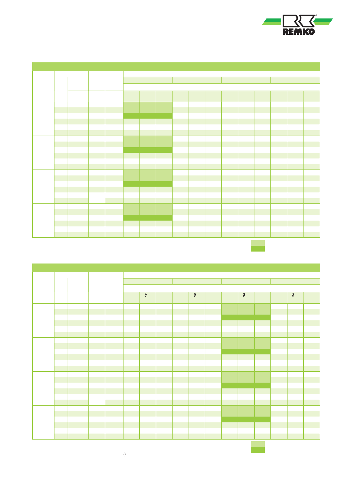
Services
Cooling capacity
Air inlet
TK 27°C,
FK19°C
KWK
100-4R
KWK
150-4R
KWK
250-4R
KWK
400-4R
Air inlet temperature TK 27°C / FK 19°C, 0% glycol concentration, spread∆t = 5K
QK = cooling capacity, total QS = cooling capacity, sensible
V = medium flow rate
Fan Unit
Flow Noise
volume
Level
min 128 25.5 34 0.83 0.63 141.8 0.53 0.53 14.6 0.37 0.37 18.3 0.26 0.19 22.6
5 147 28.5 37 0.93 0.71 158.8 0.6 0.6 14.7 0.42 0.42 18.5 0.29 0.18 23.3
4 200 34.5 43 1.18 0.93 202.5 0.78 0.78 15.3 0.54 0.54 18.9 0.38 0.14 24.9
3 252 38.5 47 1.40 1.13 240.2 0.95 0.95 15.7 0.66 0.66 19.2 0.43 0.12 25.6
2 296 39.5 48 1.57 1.29 269.5 1.07 1.07 16.1 0.75 0.75 19.4 0.48 0.09 26.1
max 333 40.5 49 1.71 1.41 293.5 1.19 1.19 16.2 0.82 0.82 19.6 0.52 0.03 26.7
min 184 25.5 34 1.22 0.92 209.5 0.78 0.78 14.3 0.54 0.54 18.2 0.37 0.29 22.3
5 194 32.5 41 1.27 0.97 218 0.81 0.81 14.4 0.57 0.57 18.2 0.37 0.33 22.0
4 254 36.5 45 1.59 1.23 273 1.04 0.98 15.4 0.72 0.72 18.5 0.43 0.39 22.3
3 304 38.5 47 1.83 1.43 314.1 1.22 1.22 14.9 0.84 0.84 18.7 0.47 0.43 22.7
2 348 41.5 50 2.03 1.61 348.4 1.37 1.37 15.2 0.94 0.94 18.9 0.51 0.47 23.0
max 388 43.5 52 2.20 1.76 377.6 1.50 1.43 15.9 1.09 1.09 18.6 0.54 0.49 23.2
min 232 26.5 35 1.57 1.17 269.3 1.10 1.10 12.8 0.69 0.69 18.0 0.40 0.40 21.8
5 254 27.5 36 1.69 1.27 290 1.18 1.18 13.0 0.75 0.75 18.1 0.43 0.43 21.9
4 353 36.5 45 2.21 1.70 379.3 1.54 1.54 13.9 1.03 1.03 18.2 0.54 0.54 22.4
3 430 41.5 50 2.57 2.01 441.1 1.81 1.81 14.4 1.20 1.20 18.6 0.61 0.61 22.7
2 505 44.5 53 2.90 2.30 497.6 2.03 2.03 14.9 1.37 1.37 18.9 0.67 0.67 23.0
max 584 47.5 56 3.23 2.59 554.3 2.26 2.26 15.3 1.53 1.53 19.1 0.80 0.80 22.9
min 283 25.5 34 1.95 1.45 334.5 1.32 1.22 14.0 0.86 0.86 17.8 0.50 0.50 86.4
5 300 26.5 35 2.10 1.53 351.9 1.54 1.30 14.0 1.02 0.90 17.9 0.55 0.52 90.2
4 423 34.5 43 2.73 2.08 468.6 1.86 1.86 13.8 1.27 1.27 17.9 0.66 0.66 114.3
3 490 37.5 46 3.08 2.37 528.8 2.13 2.10 14.1 1.45 1.45 18.1 0.73 0.73 125.3
2 570 42.5 51 3.67 2.69 595.4 2.55 2.37 14.5 1.75 1.61 18.5 0.79 0.79 137.1
max 716 47.5 56 4.12 3.26 707.1 2.82 2.82 15.1 1.94 1.94 18.9 0.90 0.90 155.5
V
[l/h]
pressure
power
dB(A) dB(A)
7 /12°C 10 /15°C 14/19°C 18/21°C
Q
K
Q
S
[kW]
[kW]V [l/h]
Q
K
[kW]
Q
S
[kW]V [l/h]
Q
K
[kW]
Q
S
[kW]V [l/h]
Q
K
Q
S
[kW]
[kW]V [l/h]
Works level 1 and 2
Rated capacity, level 3
Heating capacity
Fan Unit
Air inlet
TK 20°C,
FK14°C
Level
KWK
100-4R
KWK
150-4R
KWK
250-4R
KWK
400-4R
Air inlet temperature TK 20°C, 0% glycol concentration, spread ∆t = 5K
QK = heating capacity, total
V = medium flow rate
Flow Noise
volume
min 128 25.5 34 0.48 31 83 0.69 35.9 119.9 0.91 41.1 159.3 1.13 46 196.8
5 147 28.5 37 0.53 30.6 92 0.78 35.7 136 1.03 40.7 180 1.27 45.6 222.3
4 200 34.5 43 0.66 29.7 114.8 1.02 35.1 178 1.35 39.9 234.7 1.66 44.5 290
3 252 38.5 47 0.82 29.6 142.7 1.24 34.6 216.2 1.63 39.1 284.7 2.02 43.6 352
2 296 39.5 48 0.94 29.4 164 1.42 34.1 246.5 1.86 38.6 324.4 2.30 42.9 401.5
max 333 40.5 49 1.04 29.2 180.8 1.56 33.8 270.8 2.05 38.1 356.8 2.53 42.4 441.5
min 184 25.5 34 0.73 31.7 126.1 1.05 36.9 183 1.36 41.8 236.8 1.66 46.6 289.7
5 194 32.5 41 0.76 31.6 132.5 1.10 36.8 191.8 1.42 41.7 248.2 1.74 46.5 303.7
4 254 36.5 45 0.97 31.3 168.6 1.40 36.2 242.6 1.80 40.9 314.1 2.21 45.6 384.8
3 304 38.5 47 1.13 31 196.8 1.63 35.8 282.7 2.10 40.4 366.3 2.57 45 449.1
2 348 41.5 50 1.27 30.8 220.3 1.82 35.4 316.4 2.36 40 410.3 2.89 44.5 503.5
max 388 43.5 52 1.39 30.6 241 1.99 35.1 346 2.58 39.6 449.1 3.16 44 551.1
min 232 26.5 35 0.97 32.4 169.1 1.37 37.4 237.8 1.75 42.3 304.9 2.13 47.1 371.4
5 254 27.5 36 1.06 32.3 183.2 1.48 37.2 257.7 1.90 42 330.5 2.31 46.8 402.9
4 353 36.5 45 1.40 31.7 243.6 1.97 36.5 343.2 2.53 41.2 441.1 3.09 45.8 538.5
3 430 41.5 50 1.66 31.4 287.6 2.33 36 405.7 3.00 40.6 522.1 3.66 45.1 638
2 505 44.5 53 1.89 31.1 328.3 2.67 35.6 463.7 3.43 40 597.4 4.19 44.5 730.3
max 584 47.5 56 2.13 30.7 369.2 3.00 35.2 521.9 3.87 39.5 673 4.72 43.8 823.8
min 283 25.5 34 1.18 32.3 205.3 1.67 37.4 290 2.14 42.3 372.2 2.60 47.1 453.6
5 300 26.5 35 1.25 32.3 216.3 1.76 37.3 305.5 2.25 42.1 392.2 2.74 46.9 478.1
4 423 34.5 43 1.68 31.7 292.1 2.37 36.6 412.6 3.05 41.2 530.7 3.71 45.9 648.1
3 490 37.5 46 1.91 31.5 330.9 2.69 36.2 467.8 3.46 40.8 602.3 4.22 45.4 736
2 570 42.5 51 2.16 31.2 375.3 3.06 35.8 531.1 3.93 40.3 684.5 4.80 44.8 837.3
max 716 47.5 56 2.60 30.7 452 3.69 35.2 640.4 4.75 39.6 826.6 5.80 43.9 1012.3
V
[l/h]
pressure
power
dB(A) dB(A)
30 /35°C 40 /35°C 45/40°C 50/45°C
Q
[kW]
LA
H
LA
[°C]
= temperature air outlet, theor.
V
[l/h]
Q
H
[kW]
LA
[°C]
V
[l/h]
Q
H
[kW]
LA
[°C]
V
Q
H
[l/h]
[kW]
Works level 1 and 2
Rated capacity, level 3
[°C]
V
LA
[l/h]
19
Page 20
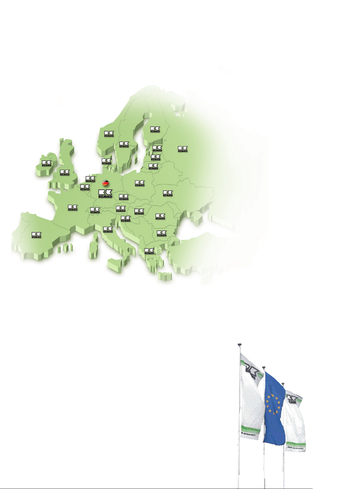
REMKO INTERNATIONAL
... and also right in your neighbourhood!
Take advantage of our experience and advice
REMKO GmbH & Co. KG
Klima- und Wärmetechnik
Consultation
Thanks to intensive training,
our consultants are always
completely up-to-date when it
comes to technical expertise.
This has given us the reputation
of being more than just an
excellent, reliable supplier:
REMKO, a partner who helps to
solve problems.
Sales
REMKO offers not just a well-
established sales network both
nationally and internationally, but
also has exceptionally highly-
qualified sales specialists.
REMKO employees in the
field are more than just sales
people: above all, they must
be advisers to our customers
in air conditioning and heating
technology.
Customer service
Our units operate precisely and
reliably. However, in the event of
a malfunction REMKO customer
service is quickly on the scene.
Our comprehensive network of
experienced dealers guarantees
quick and reliable service.
Im Seelenkamp 12 D-32791 Lage
Postfach 1827 D-32777 Lage
Telephone +49 5232 606-0
Fax +49 5232 606-260
E-mail [email protected]
Internet www.remko.de
Hotline
Air conditioning and
heating technology
+49 5232 606-0
Export
+49 5232 606-130
We reserve the right to make technical changes and provide no warranty as to the accuracy of this data!
 Loading...