

REMKO KWD EC Series, KWD 25 EC, KWD 85 EC, KWD 70 EC, KWD 35 EC Assembly And Operating Instructions Manual
...
Assembly and operating instructions
REMKO KWD EC series
Chilled water ceiling cassettes with EC fans
dual conductor version
KWD 25 EC, KWD 35 EC, KWD 45 EC, KWD 55 EC, KWD 70 EC, KWD 85 EC, KWD 100 EC
Edition GB -11 Read the instructions prior to performing any task!


Contents
Safety notes
Environmental protection and recycling
Transport and packaging
Guarantee
Unit description
System layout
Operation
Shutdown
Care and maintenance
Troubleshooting and customer service
Installation instructions for qualified personnel
Installation
Condensate drainage connection
4
4
4
5
5
6
7-16
17
17-18
19-20
21
22-25
25
Electrical wiring
Electrical drawings
Configuration, external controllers, enabling contact
Speed control with external signal control
Internal network
Leak testing
Before commissioning
Commissioning
Unit dimensions
Technical data
Exploded view of the unit
Spare parts list
Carefully read this operating manual prior to commissioning /
the units!
This operating manual is a translation of the German original.
26
27
28-29
29
30
31
31
31-32
32
33-36
37-38
37-38
using
These original instructions are an integral part of the unit and must
always be kept in the vicinity of the installation location
or on the unit itself.
Subject to modifications; no liability accepted for errors or misprints!
3

REMKO KWD EC series
Safety notes
Carefully read the operating
manual before placing the unit
in service for the first time.
It contains useful tips
as well as hazard warnings
to prevent injury or material
damage
the directions in this manual can
endanger persons, the environment
and the equipment itself and will
void any claims for liability.
■
Keep this manual close to the units.
■ The units and components
should not be exposed to any
mechanical load, and extreme
levels of humidity or sunlight.
■ Only qualified personnel may
set up and install the units
and components.
■ The set-up, connection, and
operation of the unit and its
components must take place
in accordance with the
operating conditions stipulated
in this manual and comply with
all applicable local regulations.
■ Mobile units must be set up
securely on suitable surfaces
and in an upright position.
Stationary units must be
permanently installed
for operation.
■ Modification of the units
and components supplied
by REMKO is not permitted
and can cause malfunctions.
■ Units and components may
not be operated in areas where
there is an increased risk
of damage. Observe
the minimum clearances.
. Failure to follow
and notes,
■ The operational safety
of the units and components
is only assured if they are
fully assembled and used
as intended. Safety devices may
not be modified or bypassed.
■ Do not operate units
or components if there are
obvious defects or signs
of damage.
■ All housing parts and openings
in the unit, e.g. air inlets
and outlets, must be free
of foreign objects, liquids,
or gases.
■ The units and components must
be kept at an adequate distance
from flammable, explosive,
combustible, abrasive and dirty
areas or atmospheres.
■ Contact with some parts
of the unit or components can
result in burns or other injuries.
■ Installation, repair
and maintenance work may only
be carried out by authorised
specialists. Visual inspections
and cleaning can be performed
by the operator as long
as the unit is disconnected
from the power.
■ Take appropriate precautions
when performing installation,
repair or maintenance work
or cleaning the unit to make
sure the unit does not pose
a danger to persons.
Environmental
protection
and recycling
Disposing of packaging
All products are packed
for transport in environmentally
friendly materials. Make a valuable
contribution to reducing waste
and sustaining raw materials. Only
dispose of packaging at approved
collection points.
Disposing of the units
and their components
Only recyclable materials are
used to manufacture the units
and components.
Help protect the environment
by ensuring that the units
or components (for example
batteries) are not disposed
of in household waste, but only
in accordance with local regulations
and in an environmentally safe
manner, e.g. using authorised
disposal and recycling specialists
or council collection points.
Transport
and packaging
The units are shipped in sturdy
transport packaging. Immediately
check the units on delivery
and make a note of any damage
or missing parts on the delivery
note. Inform the forwarding agent
and contractual partner.
■ The electrical power supply is
to be adapted to the requirements
of the units.
4
■ The units and components
should not be exposed to any
mechanical load, extreme levels
of humidity or direct exposure
to sunlight.
Claims under guarantee made
at a later date will not be accepted.
Guarantee
As a prerequisite for any guarantee
claims to be considered,
it is essential that the ordering
party or its representative
complete and return
the "certificate of warranty"
to REMKO GmbH & Co. KG
at the time when the units are
purchased and commissioned.
The guarantee conditions are
listed in the "General terms
and conditions". Furthermore,
only the parties to a contract
can conclude special agreements
beyond these conditions. In this
case, contact your contractual
partner in the first instance.
Unit description
In cooling mode the unit (chilled
water outlet) extracts the heat
from the interior room to be
cooled into the fin register
and passes it on to the cold
operating medium - water
or a mix of water and glycol within a closed medium cycle.
As a result of the heat exchange,
the medium heats up
and the emergent air cools
the room down.
In heating mode, a warm
operating medium warms
the room to be heated.
The medium cools down as a result
of the heat exchange.
To control the cooling or heating
capacity, a valve assembly
that is available as an accessory is
used, which routes the operating
medium through the register
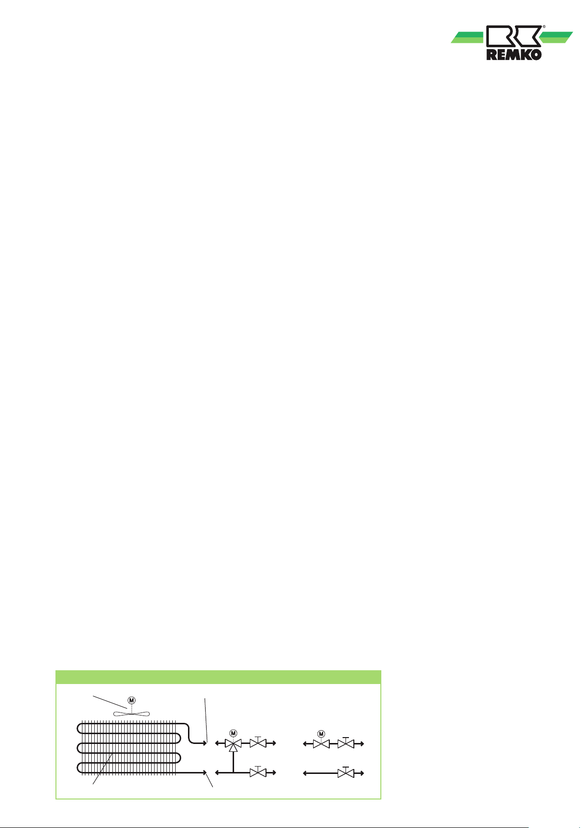
Medium cycle schematic
Recirculating fan
Medium inlet connection
M
(energy is given up) or past
the resister (energy is not given up).
The unit is designed for installation
in suspended ceilings (horizontal
installation), in an indoor area.
Thanks to the new and very robust
brushless EC fans (electronically
commutated), the energy
consumption, particularly
in the low speed range, can be
reduced significantly and the fan
speed can be adjusted infinitely
to the requirements. This also
enables an infinitely variable
output of the cooling or heating
capacity in order to obtain an even
more constant temperature
in the room.
The unit can be operated via
numerous controller options
or via an external control signal.
The applications can be adjusted
easily using jumpers. The following
controls are possible:
■
Single control using the IR remote
control provided by the factory,
alternative cabled remote control
(accessory) with five-stage fan
operation
■ Network control for up to
32 units, all units within
a group via a REMKO bus
provided by the factory
with five-stage fan operation
■ Network control for up to
32 units, specific units within
a group via a REMKO bus
provided by the factory
with five-stage fan operation
3-way valve
assembly
(Accessories)
M
2-way valve
assembly
(Accessories)
M
■ Single control using the wired
room temperature controller
(provided by the customer
or available as an accessory)
with three-stage fan operation
■ Group control using the wired
room temperature controller
and switching relay (provided
by the customer or available
as an accessory) with threestage fan operation
■ Single control via external
0 - 5V or 0 - 10V signal
(e.g. CBCS) with infinitely
variable fan operation
■ Modbus network control
via external hardware or CBCS
with infinitely variable fan
operation
The unit comprises a fin register,
an EC recirculating fan,
a condensate tray with
a condensate pump, an additional
condensate tray for the valve
assembly, swing fins, controller
with IR remote control and shape
improver, a discrete cover
for horizontal installation within
suspended ceilings.
The controller enables
the air quantity to be reduced
or increased by adjusting
the jumpers. This can also be
done retroactively and is used
to be able to react to changes
to the room's use. A potential-free
input for the "Enabling contact"
and an output for "Operating
modes" and "Cooling/heating
request" are available.
The accessories available include
room temperature controllers
for installation in the unit
or on the wall, a cooling valve
assembly and condensate pumps.
Register
Medium outlet connection
5

REMKO KWD EC series
System layout
Intended use
The unit is designed
Depending on the model
and the equipment, the units are
only intended to be used
as a cold water drain to cool
or warm the operating medium
water or a water-glycol mixture
within a closed medium cycle.
Any other use or use in a way
that exceeds the definition above
is considered
non-intended use.
The manufacturer/supplier
assumes no liability for damages
arising from non-intended use.
The user bears the sole risk
in such cases.
Using the equipment as intended
also includes working in accordance
with the operating manual
and installation instructions
and complying with the maintenance
requirements.
for a 2-conductor system.
The system has 2 medium pipes
(conductors: Supply and return
flow) for cooling using a cold
medium or heating using a warm
medium.
In cooling mode the combined
cooling register / heating register
in the indoor unit extracts the heat
from the room air by absorbing it
into the operating medium.
A circulation pump transports the
heated medium to a chiller which
extracts the heat from the medium
in an evaporator and then passes it
on to the outside air via a cooling
cycle in a condenser. The cooled
System layout
Indoor area 1
Condensate drainage line Condensate drainage line Condensate drainage line
Indoor area 2 Indoor area 3
operating medium is then fed
in once again to the unit medium
circuit.
With 2-conductor systems, which
are used for cooling or heating,
the heating capacity can
be generated through a chiller
with heat pump function
or through a boiler and fed into
the circuit. In heating operation,
the indoor unit can deliver
the heat from the operating
medium to the room air.
Condensate collecting
drainage
Cold water
drain
Outdoor area
6
Cold water
drain
Infrared remote controlInfrared remote control Cabled remote control
Chiller
Cold water
drain
Medium outlet
Medium inlet

Operation
The unit has a variety of operating
modes.
Furthermore, the fan motor can be
controlled virtually infinitely via
an external 0 - 5V or 0 - 10V signal.
The infrared remote control
provided by the factory
or the cabled remote control
Use the separate operating manuals
for this purpose.
that is available as an accessory
can be used to operate up to
32 units within a REMKO bus
or individually.
At the same time, operation can
be carried out via an external
controller with a three-stage fan
speed, via a room temperature
controller that is available
as an accessory or via a controller
that is provided by the customer
(e.g. CBCS).
Single control with three-stage fan operation via an external
controller
TIP
Help by reducing energy usage
in stand-by mode! If the unit,
the system or the components
are not being used, we
recommend disconnecting
the power supply.
Our recommendation does
not apply to safety relevant
components.
Group control with three-stage fan operation via an external
controller
Controller
provided
by the
customer
Single operation with five-stage fan operation via IR
or alternative cabled remote control
Control in REMKO networks with five-stage fan control
and group operation on all slave units
Master
CBCS
Slave Slave
Switching relay
Controller
provided
by the
customer
Operation with an external 0 - 5/10V signal and infinitely
variable fan operation via external controller
Control in REMKO networks with five-stage fan control
and single control on specific slave units
CBCS
0 - 5/10V
signal
Master
Slave Slave
alternative operation
alternative operation alternative operation
Master
addressing
Slave 1
addressing
Slave 2
addressing
7

REMKO KWD EC series
Manual mode
The unit can also be started
manually.
Press the RESET key on the receiver
unit of the cover to activate
automatic mode. In manual mode,
the following settings apply:
Cooling mode: 24 °C,
Fan speed AUTO
Heating mode: 26 °C,
Fan speed AUTO
Press a key on the infrared remote
control to interrupt manual mode.
Display
The illuminated display LEDs
indicate the set fan speed.
LED H (red) = high fan
speed
LED M (yellow) = medium fan
speed
LED L (green) = low fan
speed
Operation with IR remote
control that is fitted
as standard
The unit is easily operated using
the standard infrared remote
control. The indoor unit beeps
to acknowledge the correct
transmission of data.
If it is not possible to program
the indoor unit with the remote
control, then it can also be
manually operated.
The infrared remote control
sends the programmed settings
a distance of up to 6 m to the
receiver of the unit (fig. 1, page 7).
Data will only be received correctly
if the remote control is pointed
at the receiver and no objects are
obstructing the transmission path.
First insert the supplied batteries
(2 each, type AAA)
into the remote control.
To do so, remove the flap
from the battery compartment
and insert the batteries the correct
way around (see markings)
TIP
Help by reducing energy usage
in stand-by mode! If the unit,
the system or the components
are not being used, we
recommend disconnecting
the power supply.
Our recommendation does
not apply to safety relevant
components.
Receiver on indoor unit
Unit for receiving signals
from the remote control
CAUTION
If the LEDs, flash, a malfunction has occurred on the indoor unit.
(See chapter on troubleshooting and customer service)
NOTE
Immediately replace flat
batteries with a new set,
otherwise there is a risk
of leakage. It is recommended
that the batteries are removed
if the equipment is shut down
for longer periods.
LEDHLEDMLEDLRESET key
Manual mode
8

Keys on the remote control
1 Max. distance 6 m
max. 6 m
Keys on the remote control
"POWER" key
Press this key to start the unit.
"TEMP" key
Press this key to set the desired
temperature in 1 °C steps
within the range of 16 °C
to 30 °C.
"TIME-SET" key
Press this key to set the time.
"MODE" key
Press this key to select the
operating mode. The indoor unit
has 5 modes:
1. Automatic mode
(COOL/HEAT):
In automatic mode,
the temperature is maintained
at the constant target
temperature.
2. Cooling mode (COOL):
In cooling mode, the warm
room air is cooled to the lower
pre-set target temperature.
3. Dehumidification mode
(DRY):
In this mode, the room is mainly
dehumidified.
4. Recirculation mode (FAN)
In circulation mode, the air
is only circulated. The room
temperature is not controlled.
5. Heating mode (HEAT):
In heating mode, the cold room
air is heated to the pre-set
higher temperature.
"SWING" key
This key switches
on the oscillating fins to provide
improved air distribution
in the room. It can also be used
to lock the fins.
"FAN" key
Press this key to set the
desired fan speed. 4 stages are
available here: Automatic, high,
medium and low fan stage.
"TIME-OFF" key
This key is used to program
the automatic switch-off
function for the indoor unit.
"TIME-ON" key
This key is used to program
the automatic switch-on
function for the indoor unit.
"C" key
This key is used to activate
the time setting.
"R" key
Press this key to reset
the remote control to its factory
settings.
"NETWORK" key
Use this key to transfer the data
that was set to all other units
within a network.
"SLEEP" key
Pressing this key will
automatically increase
or decrease the target
temperature by 1 °C
within an hour in cooling mode
and heating mode respectively.
"SILENT" key
Press this key to set
a particularly low fan speed.
"TURBO" key
Press this key to set
a particularly high fan speed.
9

REMKO KWD EC series
Key functions
A symbol is shown on the display to indicate that the settings are being transferred.
POWER Key
TEMP Key
TIME Key
Press the POWER key to activate/deactivate the indoor unit. The programmed settings and parameters are shown on the display before the
unit switches off.
POWER
The TEMP key is used to set the desired target temperature in 1 °C steps.
This setting is not possible in FAN recirculation mode.
TEMP TEMP
Use a small pen or similar to press recessed key C, the time will flash
on the display. Press and hold the TIME-SET key to, at first slowly,
and then quickly adjust the clock time. Once it has been set, press
the C key again to save the time. The display will stop flashing.
RESET Key
10
TIME-SETC C
Use a small pen or similar to press recessed key R. All the symbols will
appear on the display.
After approx. 5 seconds, only the time will flash on the display.
After pressing recessed key C, press and hold the TIME-SET key to set
the time.
Once it has been set, press the C key again to save the time. The display
will stop flashing.
R 5 sec. C
Setting the time

MODE Key
Press the MODE key to change to another mode. A total of 5 modes
are available:
Auto MODE
1. COOL/HEAT
Automatic mode, automatic selection of cooling
or heating mode
2. COOL
Cooling mode, mainly used in summer
3. DRY Dehumidification mode, summer or winter mode
4. FAN Recirculation mode, no cooling or heating output
5.
HEAT Heating mode, mainly used in winter
MODE MODE MODE MODE
Press the MODE key once or repeatedly to switch to automatic mode.
In this mode, the controller automatically selects COOL or HEAT mode
depending on the temperature. The temperature is then maintained
at the set value. The prerequisite is that sufficient cooling or heating
medium at an appropriate temperature is available.
The FAN should be set to AUTO.
The target temperature is below
the room temperature
The target temperature is above
the room temperature
MODE
TEMP
COOLING
or
HEATING
Cool MODE
Dry MODE
Press the MODE key once or repeatedly to switch to cooling mode.
Use this mode to cool the room air to the desired target temperature.
Press the TEMP
/ keys to set the desired room temperature
in 1 °C steps. If the room temperature is 1 °C above the desired
temperature and sufficient coolant is available, the indoor unit will start
to cool the room air. If the actual temperature falls approx. 0.5 °C below
the set room temperature, the controller switches cooling off.
MODE
COOLING MODE
Press the MODE key once or repeatedly to switch to dehumidification
mode. Use this mode to dehumidify the room in an unregulated fashion.
After pressing the DRY key, select the desired temperature and fin
position. It is not possible to set the fan speed. The fan is switched off
at certain intervals to lower the temperature at the cooling battery.
The low temperature causes the air temperature at the fins to fall below
the dew point. Excess humidity in the air condenses on the cooling
battery and the room is dehumidified.
MODE
DEHUMIDIFICATION MODE
11

REMKO KWD EC series
Fan MODE
Heat MODE
Press the MODE key once
or repeatedly to switch
to recirculation mode.
In this mode, the unit is used
as an air circulation unit. The room
is neither heated nor cooled.
MODE
TIP
This mode allows the heat
trapped under the ceiling to be
circulated to the lower regions
of the room in winter.
CIRCULATION MODE
Press the MODE key once or repeatedly to switch to heating mode.
Use this mode to heat the room air to the desired target temperature.
The prerequisite for this is that sufficient heat is present in the cold water
system.
Press the TEMP / key to set the desired room temperature in 1 °C
steps. If the room temperature is below the set target temperature,
the three-way valve provided by the customer opens.
If there is sufficient heating medium available, the indoor unit starts
to warm up the air in the room. If the actual temperature rises approx. 1 °C
above the set room temperature, the controller switches the valve off.
NOTE
Cooling mode:
We recommend setting
the target temperature
to max. 6 °C below
the outdoor temperature.
The automatic fan speed
and swing functions should
also be used.
SWING Key
MODE
HEATING MODE
NOTE
Heating mode:
The fan will only start
when the fin temperature
reaches 38°C.
TIP
Heating mode:
We recommend setting
the target temperature
to max. 28°C. Maximum
fan speed and the lowest fin
setting should also be used.
The SWING key is used to provide continual and automatic vertical
adjustment of the fins. When switched on, the cooled air inside
the room is distributed better. If the SWING key is pressed during
the swing motion, the fins stop in their current position. Pressing
the key again resumes the swing motion.
12
SWING SWING
SWING SWING SWING SWING

FAN Key
After pressing the "FAN" key, "AUTO" is shown on the fan speed display. Each press of the key cycles through a high (H), medium (M) and
low (L) speed setting.
In AUTO mode, the controller selects the fan speed automatically. The
greater the difference between the target and actual temperature, the
higher the speed. A fixed speed is set in all stages.
SILENT Key
TURBO Key
Automatic
FAN
Stage H
FAN FAN
Stage M Stage L
Pressing the "SILENT" key sets the fan to a particularly low speed and
the fan symbol starts to flash. This stage is used to reduce the noise emissions again for example.
After pressing the "FAN" key, SILENT mode is exited.
Automatic
SILENT
SILENT stage
FAN
Pressing the "TURBO" key sets the fan to a particularly high speed and
the fan symbol for stage H starts to flash. This stage is used to cool or
heat the room faster for example.
After pressing the "FAN" key, TURBO mode is exited.
Automatic
TURBO
FAN
TURBO stage
13

REMKO KWD EC series
TIME Keys
Switch-on time
Switch-off time
The TIME-ON/-OFF keys are used to program the switch-on/off time,
the TIME-SET key to set the time.
Press the TIME-ON or TIME-OFF key to activate the timer. The clock
display then disappears. The timer symbol for the switch-on/off time
will flash. Press the TIME-SET key to set the desired switch-on/off time
in 10 minute steps.
After programming has been completed, the settings are transmitted
to the indoor unit. For delayed switch-on, press the TIME-ON key,
for delayed switch-off, press the TIME-OFF key. The timer symbol
will stop flashing and the indoor unit beeps to acknowledge
the programmed parameters.
The unit automatically switches on or off once the programmed time is
reached. If the indoor unit is switched on automatically, the previously set
mode, temperature and fan speed are activated. .
The switch-on/off time can be prematurely cancelled by pressing
the appropriate TIME key or POWER key.
Switch-on time
TIME-ON TIME-SET TIME-ON
SLEEP Key
Switch-off time
TIME-OFF TIME-SET
TIME-OFF
After the SLEEP key is pressed, the symbol is shown on the display
and the room temperature is raised or lowered by 0.5 °C in cooling
and heating mode respectively 30 minutes after the function starts up. After
a further 30 minutes, the room temperature is raised or lowered by 1 °C
in cooling and heating mode respectively. After a further hour, the room
temperature is held at a constant 2°C above or below the original target
temperature in cooling and heating modes respectively. This temperature is
then maintained at a constant level. This function is disabled by pressing
the POWER or SLEEP key. The symbol on the display extinguishes.
COOLING MODE
SLEEP SLEEP
HEATING MODE
SLEEP SLEEP
14

NETWORK Key
The NETWORK key enables the settings on the master unit (leading unit)
to be transferred to all salve units (subsequent units) on the network.
All units confirm that they have received the settings correctly by beeping.
The infrared remote controls do not copy the changed settings. Press
and hold the key for 5 seconds to transfer. However, each individual unit
can still be operated individually after this.
NETWORK
min. 5 sec.
Master / slave behaviour
Confirmation of transfer
to all units by a beep
If multiple units are installed, for example within a room, a higher-level unit (leading unit = master) can transfer
the remote control's settings to all lower-level units (subsequent unit = slave). To transfer the data, the leading
unit is connected to the subsequent units via a bus connection line (accessory). The master unit can be operated
via a standard infrared remote control or via a fixed cabled remote control (accessory). The data that is sent is
then transferred to all other slave units via the internal bus line. The number of slave units is limited to 31.
Master
00 01 02 03 04 05 31
Address
Slave
Two different network variants are available:
1. Operating a group:
Leading unit (master) function:
A standard IR or an alternative cabled remote control for the master unit can control the master
and all slave units.
Subsequent unit (slave) function:
A standard IR or an alternative cabled remote control for the slave unit can control the only
the corresponding slave unit.
2. Operating a group or specific units within a group:
Leading unit (master) function:
A cabled remote control that is available as an accessory for the master unit can control the master unit,
all slave units as a group or individual slave unit separately.
Subsequent unit (slave) function:
A cabled remote control that is available as an accessory for the slave unit can control the only the slave
unit to which it is connected.
15

REMKO KWD EC series
The following table is used to assign the relevant selected addresses to the corresponding room designation.
The procedure for assigning addresses to units is described in the "Configuration" chapter. The master unit
must be allocated address 00. Also note that the same address can also be assigned to multiple units in order
to operate a corresponding unit group.
Address Room designation
00 --> Master
01
02
03
04
05
06
07
08
09
10
11
12
13
14
15
16
17
18
19
20
21
22
23
24
25
26
27
28
29
30
31
16

Shutdown
Care and maintenance
Temporary shutdown
1.
Let the unit run for 2 to 3 hours
in circulation mode, or in cooling
mode at maximum temperature,
to extract any residual humidity
from the unit.
2. Shut down the system using
the controller.
3. Switch off the power supply
to the unit.
4. Check the unit for visible
signs of damage and clean it
as described in the "Care
and maintenance" chapter.
Permanent shutdown
Ensure that units and components
are disposed of in accordance
with local regulations, e.g. through
authorised disposal and recycling
specialists or at collection points.
REMKO GmbH & Co. KG or your
contractual partner will be pleased
to provide a list of certified firms
in your area.
Regular care and maintenance
ensure the trouble-free operation
and long service life of the unit.
CAUTION
Care and maintenance work
may only be carried out
if the unit is disconnected.
Care
■
Ensure the unit is protected
against dirt, mould and other
deposits.
■
Clean the unit using a damp
cloth. Do not use any caustic,
abrasive or solvent-based
cleaning products. Do not use
a jet of water.
■
Clean the fins on the unit prior
to long shutdown periods.
Maintenance
■
We recommend that you take
out a maintenance contract
with an annual service
from an appropriate specialist
firm.
Cleaning the cover
1. Disconnect the power supply
to the unit.
2. Open and fold down the air
inlet guard on the cover.
3. Clean the grill and cover
with a soft, damp cloth.
4.
Switch the power supply back on.
Air filter for indoor unit
Clean the air filter at intervals
of no more than 2 weeks.
Reduce this interval if the air is
especially dirty.
TIP
A maintenance contract will
guarantee that your system
always operates reliably!
Type of task
Checks / Maintenance / Inspection
General
Medium cycle bleeding
Check medium filling
Contamination of fin register
Filter contamination
Check voltage and current
Check function of fan
Check condensate drainage
Check insulation
Commissioning
Monthly
Half-yearly
• •
• •
• •
• •
• •
• •
• •
• •
• •
Yearly
17

REMKO KWD EC series
Cleaning the filter
1. Disconnect the power supply
to the unit.
2. Open and fold down the air
inlet guard on the cover.
The filter is held in place
by the flaps screwed in
at the side of the intake grill
(Fig. 2).
3. Tilt the filter and lift it out
(Fig. 3).
4. Clean the filter
with a commercially available
vacuum cleaner. Turn the dirty
side upwards to do this
(Fig. 4).
5. Dirt can also be removed
by carefully cleaning
with lukewarm water
and mild cleaning agents.
Turn the dirty side downwards
to do this
(Fig. 5).
Cleaning the condensate pump
The unit includes a builtin condensate pump for pumping
the condensate to a drain
at a higher level.
The pump is more or less
maintenance-free. The condensate
drainage lines should be checked
for dirt at regular intervals. Clean
them as required.
If an external pump is also used,
observe the care and maintenance
instructions in the separate
operating manual.
2 Air inlet grill on the cover 3 Pull out the filter
6. If water is used, let the filter
dry out properly in air before
replacing it in the unit.
7. Carefully insert the filter. Ensure
that it locates correctly.
8. Close the cover as described
above but in reverse order.
9.
Switch the power supply back on.
10.
Switch the unit back on.
4 Cleaning using a vacuum cleaner 5
Cleaning with lukewarm water
18

Troubleshooting and customer service
The unit and components are manufactured using state-of-the-art production methods and tested several
times to verify that they function correctly. However, if malfunctions should occur, please check the functions
as detailed in the list below. With systems for cooling or heating with indoor units, chillers or heating systems
the chapter "Troubleshooting and customer service" in all operating manuals must also be observed. Please
inform your dealer if the unit is still not working correctly after all function checks have been performed!
Operational malfunctions
Malfunction Possible cause Check Remedial measures
The unit does not start
or switches itself off.
Power failure, under-voltage.
Mains fuse faulty.
Master switch off.
Power supply damaged.
Waiting time after switching
on too short.
Operational temperature range
too low or exceeded.
Power surge due
to thunderstorm.
External condensate pump
alarm.
Heating mode:
Minimum heat exchanger
temperature not reached
Does all other electrical
equipment function correctly?
Are all lighting circuits
functioning correctly?
Does all other electrical
equipment function correctly?
Does a restart occur after
around 5 minutes?
Are the fans in the indoor unit
and outdoor unit working correctly?
Have there been any lighting
strikes in the area recently?
Has the pump shut down due
to a malfunction?
Is the unit in the warm-up
or cool-down phase (see
"Malfunction indicated by
flashing code")?
Check the power and wait for it
to come back on if necessary.
Replace the mains fuse.
Switch on the master switch.
Repair by specialist firm.
Plan for longer wait period.
Observe temperature ranges
of indoor unit and outdoor unit.
Turn the main fuse off
and turn it on again. Inspection
by certified service centre.
Check the pump and clean it
if necessary.
Check or increase the inlet
temperature.
The unit does
not respond
to the remote control.
Please note that this "Troubleshooting table" continues on the next page!
Transmission distance too large /
receiving problem.
Remote control is faulty
Receiver and transmitter are
exposed to too much sunlight.
Electromagnetic fields disrupt
the transmission.
Key on remote control stuck /
dual key operation.
Batteries of remote control
are flat.
Does the indoor unit beep when
pressing a key?
Is the unit running in manual
mode?
Does it function correctly
in the shade?
Does it function after
removing potential sources of
interference?
Does the "Transmitting" symbol
appear on the display?
Have new batteries been
inserted? Is the display
incomplete?
Reduce the distance to less
than 6 m and change location.
Replace remote control.
Shade the transmitter
and receiver.
Signal is not transmitted when
interference sources
are operational.
Release the key / press only
one key.
Insert new batteries.
19

REMKO KWD EC series
Malfunction Possible cause Check Remedial measures
Valve assembly jammed, not
working, not yet fully activated.
Is electrical power present
at the valve head or has
the time period of 3 minutes
after activation passed?
Have the valve head replaced
or wait for time period to pass.
The unit works
at reduced
or no cooling/heating
capacity.
Condesate is leaking
out of the unit.
Filter is dirty / air inlet / outlet
opening is blocked by debris.
Windows and doors open /
heat or cold load was increased.
Cooling mode is not set.
Inlet temperature in cooling
mode too high.
Inlet temperature in heating
mode too low.
Collector reservoir drain pipe
blocked / damaged.
External condensation pump
or floater defective.
Condensation has collected
in the condensate drainage line.
Condensate cannot
be discharged.
Float is stuck or jammed
due to excessive dirt.
Have the filters been cleaned? Clean filters.
Have structural / usage
modifications been made?
Does the "cooling" symbol
appear on the display?
Is the inlet temperature approx.
+ 5 - + 10 °C and is the
circulation pump working?
Is the inlet temperature approx.
+ 24 - + 45 °C and is the
circulation pump working?
Can the condensate drain off
without any obstruction?
Is the collection tray full of water
and the pump not running?
Is there an incline
on the condensate drainage
line and is it clear?
Are the condensate drainage lines
unblocked and is there a steady
incline? Are the condensate pump
and liquid level switch functioning
correctly?
Are the LEDs on the receiver
unit of the indoor unit flashing?
Close windows and doors /
install additional systems.
Correct the unit's settings.
Reduce inlet temperature.
Increase inlet temperature.
Clean the drainage pipe
and collection container.
Have pump replaced
by certified service centre.
Route the condensate drainage
line with an incline and clean it.
Route the condensate drainage
line with an incline and clean it.
Replace the faulty liquid level
switch or condensate pump.
Have it cleaned by specialist
firm.
Malfunction indicated by flashing code
H
(red)M (yellow)L (green)
On Fan at max. speed Normal operating condition
On Fan at medium speed Normal operating condition
Flashes
Flashes
On Flashes Flashes Register probe faulty / tripped Contact specialist dealer
Flashes
Flashes On Heat exchanger/anti-freeze protection probe >75°C Reduce the medium temperature
Flashes Flashes Heating mode: Overheating protection for indoor unit Reduce the medium temperature
Flashes Flashes Indoor unit ambient air probe faulty/tripped Contact specialist dealer
Flashes Flashes Flashes Condensation pump liquid level switch faulty/tripped Contact specialist dealer
On Flashes Window contact tripped / system in standby
20
Cause Required action
On Fan at low speed Normal operating condition
Heating mode: Warm-up phase, fan not active, heat exchanger
temperature <28/36°C (corresponds to DIP3, SW5)
Heating mode: Cool-down phase, fan active
(only for DIP3 configuration, SW7 = ON)
Cooling mode: Indoor unit anti-freeze protection <2°C
for 10 minutes
Wait approx. 1 minute
Wait approx. 1 minute
Increase the medium
temperature
Open the enabling contact
(terminals 3 + 4)

Installation instructions for qualified personnel
Important notes prior
to installation
■
Observe the operating manuals
for the indoor unit and the
chiller or heating system when
installing the entire system.
■
The indoor units and chillers
work independently.
A connecting line between
the two is not necessary.
■
Transport the unit in its original
packaging as close as possible
to the installation location.
You avoid transport damage
by doing so.
■
Check the contents of the
packaging for completeness
and check the unit for visible
transport damage.
Report any damage immediately
to your contractual partner
and the shipping company.
■
Select an installation location
which allows air to flow freely
through the inlet and outlet.
(See section "Minimum
clearances").
■
Do not install the unit in the
immediate vicinity of devices
which generate intensive
thermal radiation.
Installation in the vicinity
of thermal radiation reduces
the unit output.
■
Lift the unit at the corners
and not by the medium
or condensate connections.
■
The medium connection lines,
valves and connections must
have vapour density insulation.
If necessary, also insulate
the condensate drainage line.
In dual systems with cooling
and heating modes,
the requirements of the current
Energy Savings Ordinance
(EnEV) are to be complied with.
■
Seal off open lines to prevent
dirt getting in and never kink
or crimp the lines.
■
Avoid unnecessary bends.
This minimises the pressure loss
in the lines.
■
Make all electrical connections
in accordance with applicable
DIN and VDE standards.
■
Always attach electrical lines
properly in electrical clamps
(otherwise a fire could result).
■
Service openings should be
provided in the suspended
ceiling to allow maintenance
access to the control box
or the valve assembly.
■
Any ventilation ducts or pipes
and connection fittings, which
are used to connect a second
room or supply fresh air, should
be insulated with diffusion-tight
material.
■
Only install the valve assembly
or other attachments once the
indoor unit has been installed.
Installation material
The unit is attached using
4 threaded rods provided
by the customer.
In order to be able to complete
installation, wall plugs, trapezoidal
sheet metal supports, steel profiles,
fixing clamps for medium
and condensate drainage lines
(as well as laying ducts),
and connection fittings
for condensate drainage lines
are required.
Selecting the installation location
The unit is specifically designed
for horizontal mounting
in suspended ceilings
with Euroraster dimensions.
However, it can also be installed
in suspended ceilings with different
dimensions.
Take into account the installation
height of the units.
Minimum clearances
Observe the minimum clearances
to allow access for maintenance
and repair work in the suspended
ceiling and to facilitate optimum
air distribution for the cover.
NOTE
If the unit is operated
in heating mode, the maximum
installation height of 2.7m
must not be exceeded
and a cabled remote control
must be used if necessary.
Minimum clearances
KWD 25 EC to KWD 55 EC
300
300
300
KWD 70 EC to KWD 100 EC
300
300
300
300
300
300
300
Dimensions in mm
21

REMKO KWD EC series
Installation
Unit installation
The unit is mounted with the cover
face down on four threaded rods.
Take into account the ceiling grid
and any other installations.
1. Use the dimensions
of the ceiling cassette
to mark the fixing points
for the threaded rods
on structural parts approved
to support the static load
above the suspended ceiling.
2. Fit any connection nozzles
before installing the unit
if connections to a second
room or a fresh air intake
are required.
See the "Connections
to a second room or a fresh air
intake" section.
CAUTION
Installation should only be
performed by authorised
specialists.
6 Hooking in the unit
Unit mount
KWD 25 EC-55 EC
280
615
KWD 70 EC-100 EC
810
615
Dimensions in mm
3. Fit the unit onto the threaded
rods and use the lower nuts
to level the unit (Fig. 6).
This ensures that the condensate
drains into the collection tray.
4. Make sure that clearance A,
as specified in the table below,
is maintained between
the underside of the suspended
unit and the underside
of the fastening (Fig. 7).
5. Connect the refrigerant piping,
electrical cables and condensate
drainage line to the indoor unit
as described below.
6. Check again that the unit
is level.
7. The final task is to tighten
the counter nuts and attach
the cover.
Dimensions
in mm
Distance A 35 35
Distance B 25 25
Unit mount 615 x 280 615 x 810
7 Fastening the unit
Dimension A
Dimension B
Dimension B
Dimension A
KWD
25 EC-
55 EC
KWD
70 EC-
100 EC
Connection for medium
piping
■ The piping connection provided
by the customer is carried out
on an angled side of the unit
on the KWD 25 EC-55 EC
and in the middle of the longer
side on the KWD 70 EC-100 EC.
■
For servicing purposes,
connections must be equipped
with shut-off valves and flow
volumes adjusted using valves
for hydronic balancing.
■
Additional automatic bleed
valves are to be provided
in the supply and return
at the installation's highest point.
■
The medium piping may not
exert any structural load
on the unit.
■
The line connections may
not generate any thermal
or mechanical stresses
on the unit.
If necessary cool the piping
or support with the second tool.
22

Required system components
Valve assembly (accessory)
In 2-conductor systems, cold
or warm medium is fed through
the register in the unit and cold
or warm air can then be released.
Control is provide by the 3-way
valve assembly. It comprises
the electrically actuated valve
head and the valve body.
If the head is electrically activated,
it actuates the body, which routes
the medium into the register.
If the temperature is reached
then the head is switched off
and the medium is fed through
the bypass past the register.
The bypass serves to ensure
the minimum medium flow rate
for the chiller.
increases and the unit's cooling
or heating capacity reduces.
All system components must be
approved for use with glycol.
CAUTION
When disposing, the product
requirements of the glycol
type which is used must be
observed.
Diaphragm expansion vessel (DEV)
To avoid pressure fluctuations
during standstill because
of temperature changes,
diaphragm expansion vessels filled
with nitrogen (moisture neutral)
must be integrated in the system.
CAUTION
Glycol tolerant air vent valves
are necessary when using
media that contain glycol.
Manual bleeding
Manual bleeding
Valve body
Valve head
Shut-off
Additional
condensate tray
Manual drainage
Condensate tray
(standard equipment)
valves
NOTE
The time between being fully
open and fully closed can be
approx. three minutes.
Valves for hydronic balancing
The calculated individual pressure
losses in the pipeline network
layout for each individual unit are
adjusted to the entire system
with pipe leg regulating valves
to be provided on-site.
The nominal flow rates
for the medium adjust
to the necessary values
as a consequence
of the pressure loss.
Anti-freeze protection (accessories)
A water glycol mix is generally
used as medium for a cold water
system. Depending on the use
to which the glycol type
and quantity is put, the viscosity
changes, the loss in pressure
NOTE
No moisture can condense
in the nitrogen filler.
Safety valve
Safety valves limit excess operating
pressure due to excess warming
or overfilling of the operating
medium. The valve outlet requires
unobstructed draining into a drain
line. Applicable local disposal
ordinances must be observed
if glycol is used.
Automatic bleed valves
The unit has one or two manual
bleed valves on the collector pipe
of the register. The unit can be
bled separately after the system
has been filled.
Automatic air vent valves must
also be installed at the highest
point in the collective lines.
The delivery includes an additional
condensate tray for installation
on the side of the unit
in the suspended ceiling. This is
required to catch the condensate
that arises on a valve assembly
or on the valves provided
by the customer.
Subsequently check the incline
and that it is functioning correctly.
Connections to adjoining
room and fresh air intake
The unit has been designed
to enable cooling a second
room and taking in fresh air
independently of this.
Connections to adjoining room
and fresh air intake
KWD 25 EC-55 EC
Fresh air
connection
Adjoining room connection
23

REMKO KWD EC series
Connections to adjoining room
and fresh air intake
KWD 70 EC-100 EC
Fresh air connection
Adjoining room connection
CAUTION
Only one fresh air and one
adjoining room connection are
permitted to be used!
8 Remove the cut-out
9 Remove the insulation
10 Break through the opening
11
Install the nozzles
Installation instructions
Proceed as follows to make
the connections to a second room
and the fresh air intake:
1. Note that the exchanger fins
are located directly behind the
opening being removed. These
should not be damaged under
any circumstances (Fig. 8).
2. Carefully remove the insulation
behind the opening (Fig. 9).
3. Break through the appropriate
opening
(Fig. 10).
4. Keep the ventilation pipes
as short as possible and lay
them in such as way
as to minimise the number
of bends.
5. The collars, screws, flexible /
folded spiral seam pipes
and insulation materials must
be provided by the customer.
These items can be obtained
from specialist suppliers
(Fig 11).
Adjoining room connection
The unit can also be used to cool
an adjoining room through a duct
system, e.g. hidden behind
a suspended ceiling. The following
prerequisites must be met for this:
■
Observe the regional
regulations concerning
air treatment.
■
Fit a collar with a nominal
diameter of 100 mm to the
adjoining room connection
■
The cooling capacity of the
.
indoor unit must be sufficient
for both rooms.
■
An opening must be made
between both rooms to allow
the air to circulate.
■
The maximum pipe length
of 7 m must not be exceeded
(page 22, Fig. 12).
■
In order to ensure that the air
is transported to the adjoining
room, close off 1 or 2 of the 4
outlets on the cover.
Stick a black single-sided
adhesive fabric strip over the
outlet openings being covered.
This strip must be able
to withstand the effects
of a continual air flow.
Fresh air connection
The unit can also be employed
to suck in and regulate the
temperature of fresh air (outdoor
air), in addition to room air.
This is the preferred option
for rooms with a high rate
of air consumption.
■
Observe the regional
regulations concerning
air treatment.
■
Fit a collar with a nominal
diameter of 100 mm to the
fresh air connection
(page 22, Fig. 13).
■
The fresh air content should
not exceed 10% of the nominal
air flow rate for the unit.
The fresh air supply should
be controlled by an additional
speed-regulated fan.
■
The air at the outdoor air intake
should be sucked in through
a dust filter at a maximum
rate of 2.5 m/s to prevent
the ingress of rain water.
■
The fan should be connected
to a separately protected
electrical supply that is to be
provided by the customer.
24

12 Adjoining room connection
max. 7 m
13 Fresh air connection
Outdoor
air inlet
Main room
Adjoining room
Condensate drainage connection
If the temperature falls below
the dew point, condensate will
form on the cooling fins during
cooling mode.
A collection tray together
with a condensate pump and liquid
level switch are fitted as standard
below the cooling fins. If the liquid
level switch trips a protective
shutdown due to inadequate
removal of the condensate,
the pump will switch
on immediately and run on
for approx. three minutes.
■
The condensate drainage line
provided by the customer
should have an incline
of at least 2 %. If necessary,
fit vapour-diffusion-proof
insulation.
Condensate drainage connection - Incorrect!
Riser pipe too far away Condensate drainage line too large/small
■
If the level of the condensate
drainage line on the unit is
above that of the outlet, route
the pipe vertically upwards
and then with an incline
to the drain.
■
Route the condensate drainage
line of the unit freely into the
drain line. If the condensate
runs directly into a sewer
pipe, fit a trap to prevent
any unpleasant odours.
■
When operating the unit
at outdoor temperatures below
0°C, ensure the condensate
drainage line is laid to protect it
against frost. If necessary,
fit a pipe heater.
Inside Outside
■
After installation is complete,
check for unobstructed
condensation run off
and ensure that a permanent
seal is provided.
CAUTION
The max. pump pressure
of the condensate pump
is 1000 mmWS. Capacity
reductions can result
from external influences such
as air-side counter-pressure,
soiling or wear. In order
to guarantee safe functional
operation, we recommend
observing a maximum delivery
height of 800 mm!
Condensate drainage
connection - Correct!
min. 2% incline, free inlet
No incline/rise
16-20 mm
Max. flow rate
1000 mmWS,
Recommendation:
max. 800 mm
height difference
Cannot freely drain away, air-side counter-pressure
max. 100 mm
25

REMKO KWD EC series
Electrical wiring
CAUTION
All electrical installation work
is to be performed by specialist
companies. Disconnect the
power supply when connecting
the electrical terminals.
■
We recommend installing
a master / repair switch
provided by the customer
close to the indoor unit.
■
The power supply is made
at the indoor unit, a control line
to the chiller is not necessary.
■
If a condensate pump, which
is available as an accessory,
is used in conjunction with
the unit, the pump switch-off
contact switches off the power
supply or the valve if necessary.
■
The terminal block is located
inside the unit. It can be
accessed after opening
the cover.
CAUTION
Check all plug and terminal
connections to verify
that they are tight and make
a permanent contact. Tighten
as required.
KWD 25 EC to 100 EC control box
Control box cover
KWD 25 EC to 100 EC
Proceed as follows to connect:
1. Open the control box cover
by removing the fixing screws
and lifting off the cover.
2. Feed the de-energised cable
through the edge protection
rings on the control box
and clamp the cable
in the strain relief.
3. Then connect the cable
in accordance with the
connection diagram.
4. Connect the electrical plugs
on the cover to the mating
connectors on the cassette.
It is not possible to incorrectly
connect these.
5. Configure the unit according
to its use via the switch blocks
and the terminal connections.
6. Install all removed parts.
Measurement
temperature
C°
-20 37.4 kΩ
-15 29.0 kΩ
-10 22.7 kΩ
-5 17.9 kΩ
0 14.2 kΩ
+5 11.4 Ω
+10 9.1 kΩ
+15 7.4 kΩ
+20 6.1 kΩ
+25 5.0 kΩ
+30 4.1 kΩ
+35 3.4 kΩ
+40 2.9 kΩ
+45 2.4 kΩ
+50 2.0 kΩ
+55 1.7 kΩ
+60 1.5 kΩ
+65 1.3 kΩ
+70 1.1 kΩ
+75 0.9 kΩ
Probe
resistance value
26

Electrical drawings
KWD 25 EC to 100 EC
IR receiver cover
Probe, ambient air
Anti-freeze protection
probe
Internal Lcom network
Internal Lcom network
DIP3 switch block
Function configuration
DIP2 switch block
Network configuration
JP 1: Jumper plugged in/closed
for the last unit on an internal network
JP 2: Select the fan motor control voltage
open = 0 - 5VDC
plugged in = 0 - 10VDC
DIP1 switch block
Unit configuration
Potential-free contact
Potential-free contact
Heating request
Cooling request
Potential-free contact
Potential-free contact
Cooling mode
Heating mode
Potential-free contact
General alarm signal
Power supply
230V, 50Hz
Phase conductor
Neutral conductor
Earth conductor
Cabled remote control
(accessory)
Swing motor Sm 1-4
Swing motor Sm 5/6
only KWD 70-100 EC
Valve assembly connection
for 230V valve heads
Fan motor 1
Fan motor 2
only KWD 70-100 EC
Liquid level switch
CON8: Select the external
control voltage
open = 230VAC
plugged in = 24VAC
Condensate pump
Fuse
Condensate
pump
Key
Wt = white
Gn = green
Ye = yellow
Pk = pink
Gn/Ye = green/yellow
Bl = blue
Bn = brown
Bk = black
Gr = grey
External input
3 speed stages
External input, potential-free
Enabling contact
External control voltage 0 - 5/10V
Fan motor control
Vi = violet
Or = orange
Rd = red
low
medium
high
automatic
External 24VAC power supply
27
REMKO KWD EC series
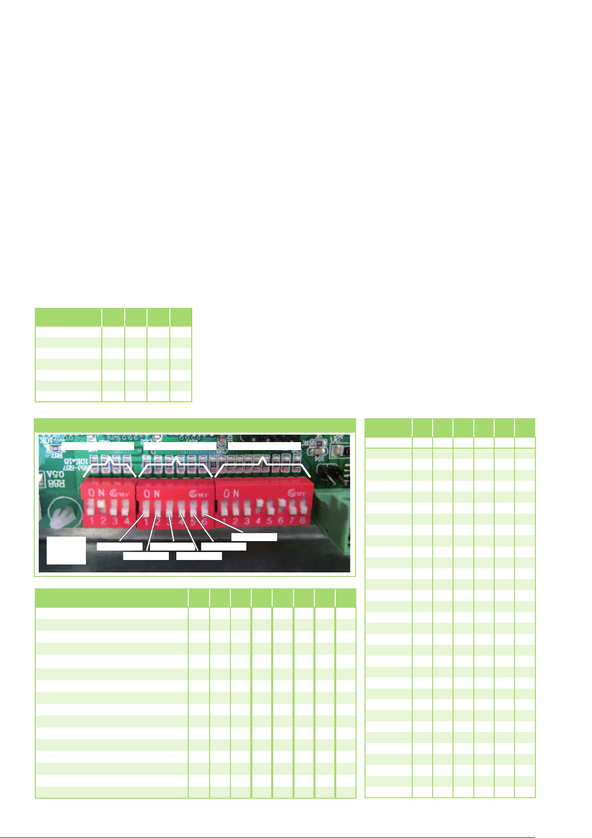
Configuration
The units can also be adjusted
to requirements retroactively
by adjusting DIP switch blocks
1 to 3 accordingly.
DIP switch block 1 configures
unit-specific parameters and must
be set in accordance with the
table below. DIP switch block 2
configures the network addresses
within a bus and DIP switch block 3
configures the unit's functions.
DIP1:
Unit type
KWD 25EC ON OFF OFF OFF
KWD 35EC ON OFF OFF OFF
KWD 45EC OFF ON OFF OFF
KWD 55EC OFF OFF ON OFF
KWD 70EC ON OFF OFF OFF
KWD 85EC ON ON OFF OFF
KWD 100EC OFF OFF ON OFF
SW 1SW 2SW 3SW
4
Configuration is carried out using
white slide switch SW1-4 for DIP1,
SW1-6 for DIP2 and SW 1-8
for DIP3.
The following settings must be
made according to usage before
starting up for the first time.
Unit configuration (DIP1)
Adjusting this DIP switch provides
the controller with specific key
variables that are required
for safe control behaviour
and optimised unit operation.
Only the configuration specified
for the relevant unit is permitted
to be used here, as this is the
only way to guarantee optimised
control behaviour.
Network configuration (DIP2)
The addresses for the leading
(master) and subsequent (slave)
units are defined using switch
block DIP2.
Function logic (DIP3)
The units can be used
for numerous applications
and requirements. The following
settings are possible using switch
block DIP3:
SW 1-3: 2- or 4- conductor function
SW 4: Use of a valve
SW 5: Fan function
in the warm-up phase
SW 6: Fan communication
SW 7: Fan function in re-heat
mode
SW 8: internal/external controller
DIP switch blocks 1 to 3
DIP switch block 1
Example:
SW1 to 6
on DIP2
DIP3:
Function logic
2-conductor cooling/heating OFF OFF OFF
2-conductor with electrical heating register (backup)
2-conductor only cooling mode OFF ON OFF
2-conductor with electrical heating register (1st stage)
4-conductor without electrical heating
register
4-conductor with electrical heating register (backup)
Use of a control valve ON
Use without a control valve OFF
Heating mode fan operation >36°C ON
Heating mode fan operation >28°C OFF
Close-loop fan operation ON
Open-loop fan operation OFF
Re-heat mode fan not active ON
Re-heat mode fan active OFF
Use of the internal controller ON
Use of external controllers OFF
Switch SW1
DIP switch block 2 DIP switch block 3
Switch SW3
Switch SW2
Switch SW5
Switch SW4
SW 1SW 2SW 3SW 4SW 5SW 6SW 7SW
OFF OFF ON
OFF ON ON
ON ON OFF
ON ON ON
Switch SW6
8
DIP2:
Network
Master OFF OFF OFF OFF OFF ON
Slave 1 OFF OFF OFF OFF OFF OFF
Slave 2 ON OFF OFF OFF OFF OFF
Slave 3 OFF ON OFF OFF OFF OFF
Slave 4 ON ON OFF OFF OFF OFF
Slave 5 OFF OFF ON OFF OFF OFF
Slave 6 ON OFF ON OFF OFF OFF
Slave 7 OFF ON ON OFF OFF OFF
Slave 8 ON ON ON OFF OFF OFF
Slave 9 OFF OFF OFF ON OFF OFF
Slave 10 ON OFF OFF ON OFF OFF
Slave 11 OFF ON OFF ON OFF OFF
Slave 12 ON ON OFF ON OFF OFF
Slave 13 OFF OFF ON ON OFF OFF
Slave 14 ON OFF ON ON OFF OFF
Slave 15 OFF ON ON ON OFF OFF
Slave 16
Slave 17 OFF OFF OFF OFF ON OFF
Slave 18 ON OFF OFF OFF ON OFF
Slave 19 OFF ON OFF OFF ON OFF
Slave 20 ON ON OFF OFF ON OFF
Slave 21 OFF OFF ON OFF ON OFF
Slave 22 ON OFF ON OFF ON OFF
Slave 23 OFF ON ON OFF ON OFF
Slave 24 ON ON ON OFF ON OFF
Slave 25 OFF OFF OFF ON ON OFF
Slave 26 ON OFF OFF ON ON OFF
Slave 27 OFF ON OFF ON ON OFF
Slave 28 ON ON OFF ON ON OFF
Slave 29 OFF OFF ON ON ON OFF
Slave 30 ON OFF ON ON ON OFF
Slave 31 OFF ON ON ON ON OFF
Slave 32 ON ON ON ON ON OFF
SW 1SW 2SW 3SW 4SW 5SW
6
ON ON ON ON OFF OFF
28

Using extneral
controllers
The units can be controlled
using the controller provided
by the factory or using an external
controller.
The external controller can be used
to activate the three Fan stages,
"High", "Medium" and "Low".
The operating voltage of 24V
or 230V can be selected via
the open or closed CON 8
strapping plug.
When connecting external
controllers, e.g. central building
control systems (CBCS), DIP switch
block DIP3 on the SW8 must be
configured to "OFF"
and the CON 8 strapping plug
must be removed.
The valve head for the valve
assembly to control the medium
flow rate can be controlled directly
using the controller.
External controller
Circuit diagram
CON 8 strapping plug
Power supply 230V,
50Hz or 24V, 50Hz
Strapping plug
24VAC 230VAC
External control voltage CON 8
24 VAC (factory setting) Closed
230 VAC Open
Controller used DP3 SW8
External controller active OFF
Internal controller active ON
DIP3 SW8
Using an enabling
contact
Some applications require the units
to be enabled or blocked, e.g.
if cooling is to be interrupted
when the window is open.
A potential-free contact can be
connected to terminals 3 and 4.
This blocks unit operations after
it has been short-circuited
for 5 seconds and enables unit
operation once it has been open
for 2 seconds.
External enabling contact
Circuit diagram
Unit operating Unit not operating
(after 5 seconds)
Speed control with external 0 - 5/10V DC
signal control
The units with EC fans allow
for virtually infinitely variable
speed adjustment depending
on the design. This setting can
also be specified using an external
control signal in the range
of 0 - 5V DC or 0 - 10V DC
on terminals 1 (+) and 2 (-)
(observe the polarity!).
External 0 - 5/10V signal control
Circuit diagram JP2 and DIP3 SW8
Unit operating
The external controller is selected
via DIP3 SW8 = OFF
and by setting the voltage
that is specified via jumper JP2.
Once it is connected, the internal
controller can no longer be used
for operation.
A 0 - 5/10V control valve can
also be controlled in parallel
on the same terminals.
External control
voltage
0 - 10 VDC Closed
0 - 5 VDC
(factory setting)
Controller used DIP3 SW8
External controller
active
Refer to the "Use of external
controllers" chapter!
JP2
Open
OFF
29

REMKO KWD EC series
Using the internal
network
Up to 32 units can be operated
at the same time thanks to the
parallel connection via a bus line
(accessory). The units can access
this network (internal network)
at the same time.
The network can have one
leading unit (master) and up to 31
subsequent units (slave).
The units are connected together
via a three-core, shielded bus line.
The minimum cross section
is 1.0 mm² with a maximum line
length of 500m in the network
(observe the polarity!).
The end of the network must be
marked by the plugged in
jumper JP1.
The addresses are assigned
by adjusting switches SW1 to SW6
(see the "Configuration" chapter).
Network with infrared remote
controls
■
The standard infrared remote
control operates a master unit.
All slave units are set according
to the programming.
■
The infrared remote control
or the cabled remote control
(accessory) can be used
for user-specific operation
of an individual slave unit.
Execution
■
Address assignment for the
units is carried out by changing
the DIP switch settings
for DIP switch block 2.
Network with cabled remote
controls
■
The cabled remote control
that is available as an accessory
operates a master unit. All slave
units with cabled remote controls
can be programmed individually
from the master unit directly
or as a complete group.
■
The cabled remote control
(accessory) can be used
for user-specific operation
of an individual slave unit.
Execution
■
The addresses for the master
and slave units are assigned
by configuring the cabled
remote control
(see the separate installation manual).
Internal network wiring diagram
Network line to the next
unit is possible
Network line provided by the customer
Unit no. 0
(Master)
3-core, shielded
JP1 plugged in indicates the last
unit in the network
3-core, shielded
Network line provided by the customer
Unit no. 1
(Slave)
Last unit
(Slave)
Unit no. 2
(Slave)
3-core, shielded
Network line provided
by the customer
Last unit
but one
(Slave)
30

Leak testing
Before commissioning
Commissioning
Once the connection has been
established successfully, the leak
test is carried out.
1. Flush the system twice
with tap water.
2. Clean the sieve insert
on the dirt trap.
3. Fill the system with water
again and bleed the unit
at the manual bleed valves.
4. Adjust the test pressure
to at least 200 kPa (2.0 bar).
5. Check the connections after
a period of at least 24 hours
for leaking water. If water
is visible, the connection has
not been established properly.
Tighten the connection
or establish a new connection.
6. After a successful leak test,
remove the excess pressure
from the medium piping
if a water-glycol mixture is used
or adjust the non-circulating
pressure to the required system
pressure.
NOTE
During manual bleeding,
escaping glycol mixtures
must be disposed of separately.
Do not feed them into the
condensate tray!
Manual bleeding
Anti-freeze protection
for the medium
If a water-glycol mixture is used,
it is to be pre-mixed before being
put in the system. The desired
concentration is then to be checked.
Bleeding the system
■
Air may still be in the pipe
lines after the leak test.
This is carried during operation
of the circulation pump to the
automatic bleeding valves
or to the cold water drain. It is
necessary to bleed again here.
■
The non-circulating pressure
must then be adjusted to the
required system pressure.
DEV
■ The preliminary pressure
for the diaphragm expansion
vessel must be adjusted
individually to the system
layout, the volume of the
medium and the installation site.
Valves for hydronic balancing
■
The calculated excess pressure
in the pipe network layout
at the individual cold water
outlets must be adjusted
on the pipe leg regulating
valves.
Safety valve
■
The safety valves and their correct
function must be checked.
■
The drain line for the valves is
to be checked for function
and leak tightness.
Configuration setting
■
Commissioning should only be
performed and documented
by specially trained personnel.
■
Observe the manuals for the
unit and all other components
when commissioning the entire
system.
■
Commissioning should only be
performed and documented
by specially trained personnel.
■
Observe the manuals for the
unit and all other components
when commissioning the entire
system.
Function test for cooling
operating mode
1. Switch the power supply on.
2. Open all shut-off valves
if necessary.
3. Switch on the chiller
and the corresponding
circulation pump. The outlet
temperature must be
between +4 and +18 °C.
4. Use the remote control
to switch on the unit and select
the cooling mode, maximum
fan speed and lowest target
temperature.
5. Measure and record all
the required values in the
commissioning report
and check the safety functions.
6. Check the unit control system
using the functions described
in the "Operation" chapter.
7. Check that the condensate
drainage line is functioning
correctly by pouring distilled
water into the condensate tray.
A bottle with a spout is
recommended for pouring the
water into the condensate tray.
Manual bleeding
Manual drainage
■
Before the electrical voltage is
applied to the unit for the first
time, the settings described
in the "Configuration" chapter
must be made according
to the use.
31

REMKO KWD EC series
Function test of heating operating
mode
1. Switch the power supply on.
2. Open all shut-off valves
if necessary.
3. Switch on the heating system
and the corresponding
circulation pump. The outlet
temperature must be
between +35 and +70 °C.
Unit dimensions
KWD 25 EC to 55 EC
650
650
4. Use the remote control
to switch on the unit and select
the heating mode, maximum
fan speed and highest target
temperature.
5. Measure and record all
the required values in the
commissioning report
and check the safety functions.
60
6. Check the unit control system
using the functions described
in the "Operation" chapter.
Final tasks
■
Reassemble all disassembled
parts.
■
Familiarise the operator
with the system.
280
615
KWD 25 EC to 45 EC
580
258
28
Outlet: 3/4“ F
Inlet: 3/4“ F
100
KWD 70 EC to 100 EC
690
1220
1110
KWD 55 EC
Condensate drainage
connection: 19 mm
207
185
150
Condensate drainage connection: 19 mm
298
28
Outlet: 3/4“ F
Inlet: 3/4“ F
580
100
580
810
Condensate drainage
connection: 19 mm
245
230
190
615
32
298
28
Outlet: 3/4“ F
Inlet: 3/4“ F
100
250
135
195
100
All measurements in mm

Services
Cooling capacity
Fan stage
1 180 20.8 0.21 3.4 1.38 0.89 1.10 0.81 0.94 0.62 0.72 0.54 0.56 0.39
KWD
25 EC
KWD
35 EC
KWD
45 EC
KWD
55 EC
KWD
70 EC
KWD
85 EC
KWD
100 EC
2 220 21.9 0.29 5.1 2.05 1.73 1.63 1.05 1.39 0.92 1.06 0.84 0.82 0.69
3 320 23.5 0.37 7.0 2.71 1.88 2.15 1.53 1.84 1.35 1.40 1.23 1.08 1.01
4 390 25.1 0.41 9.0 2.95 2.05 2.34 1.66 2.00 1.46 1.53 1.33 1.17 1.10
5 440 27.4 0.45 10.2 3.21 2.54 2.55 1.81 2.18 1.59 1.66 1.45 1.28 1.20
1 220 21.9 0.29
2 320 23.5 0.37 7.0 2.71 1.73 2.15 1.53 1.84 1.35 1.40 1.23 1.08 1.01
3 390 25.1 0.41 9.0 2.95 1.88 2.34 1.66 2.00 1.46 1.53 1.33 1.17 1.10
4 440 27.4 0.45 10.2 3.21 2.05 2.55 1.81 2.18 1.59 1.66 1.45 1.28 1.20
5 520 33.0 0.55 15.0 3.98 2.54 3.16 2.24 2.70 1.97 2.06 1.80 1.58 1.48
1 215 22.5 0.30 5.0 1.98 1.20 1.63 1.05 1.27 0.93 1.04 0.82 0.87 0.69
2 343 26.9 0.43 9.2 3.05 1.91 2.51 1.68 1.96 1.49 1.60 1.32 1.34 1.10
3 397 29.5 0.49 11.3 3.46 2.14 2.84 1.88 2.22 1.67 1.82 1.47 1.52 1.23
4 566 37.7 0.65 18.2 4.59 3.06 3.77 2.69 2.94 2.39 2.41 2.11 2.01 1.76
5
1 229 21.4 0.33 6.0 2.19 1.23 1.80 1.08 1.45 0.95 1.20 0.80 0.97 0.67
2 606 35.9 0.68 14.8 4.74 3.12 3.89 2.74 3.13 2.42 2.59 2.03 2.09 1.70
3 665 38.0 0.72 16.2 5.02 3.40 4.12 2.98 3.32 2.63 2.74 2.21 2.21 1.85
4 793 42.5 0.8 18.7 5.63 3.85 4.62 3.38 3.72 2.98 3.07 2.51 2.48 2.10
5 974 47.9 0.91 23.1 6.34 4.58 5.20 4.02 4.19 3.55 3.46 2.98 2.79 2.50
1 385 28.1 0.56 12.8 3.31 2.16 2.96 1.68 1.96 1.45 1.64 1.26 1.30 0.68
2 610 29.7 0.67 17.4 4.50 3.15 4.02 2.71 2.67 2.11 2.22 1.83 1.76 1.00
3 700 30.3 0.76 21.5 5.47 3.93 4.89 3.38 3.25 2.63
4 780 34.6 0.84 24.2 6.03 3.97 5.39 3.41 3.58 2.65 2.98 2.31 2.36 1.26
5 1030 37.9 0.98 29.7 7.75 5.69 6.93 4.89 4.60 3.80 3.83 3.31 3.04 1.80
1 398 27.9 0.55 6.1 3.51 2.29 2.98 1.93 2.35 1.83 1.91 1.60 1.56 1.41
2 671 34.6 0.87 19.0 5.94 4.18 5.04 3.53 3.97 3.35 3.23 2.92 2.64 2.58
3 771 43.5 1.20 26.5 8.31 5.79 7.05 4.89 5.56 4.65 4.52 4.05 3.70 3.57
4 1096 45.7 1.29 30.8 8.88 6.21 7.54 5.24 5.94 4.98 4.83 4.34 3.95 3.83
5 1322 50.7 1.45 40.0 9.91 6.87 8.41 5.80 6.63 5.51 5.39 4.80 4.41 4.24
1 393 28.2 0.55 6.1 3.28 2.22 2.98 1.93 2.25 1.85 1.86 1.49 1.52 1.28
2 1057 45.0 1.20 26.5 7.75
3 1157 46.2 1.29 30.8 8.29 6.03 7.54 5.24 5.69 5.02 4.71 4.05 3.86 3.46
4 1380 48.0 1.50 41.4 9.34 6.64 8.50 5.77 6.42 5.53 5.31 4.46 4.35 3.81
5 1678 53.2 1.66 49.5 10.64 7.70 9.68 6.69 7.31 6.41 6.05 5.17 4.95 4.42
Medium inlet
Medium nominal
5 °C 7 °C 9 °C 11 °C 13 °C
Cooling capacity
Flow
volume
[m3/h]
Sound pressure level
Air flow rate
Pressure
loss
[kPa]
QK
[kW]QS[kW]QK[kW]QS[kW]QK[kW]QS[kW]QK[kW]QS[kW]QK[kW]QS[kW]
5.1 2.05 1.19 1.63 1.05 1.39 0.92 1.06 0.84 0.82 0.69
684 42.8 0.78 25.1 5.33 3.53 4.38 3.10 3.42 2.75 2.80 2.43 2.34 2.03
2.70 2.29 2.15 1.24
5.63 7.05 4.89 5.32 4.69 4.41 3.78 3.61 3.23
Cooling:
Air inlet temperature TK 27 °C / FK 19 °C, 0 % Glycol concentration, spread 5K
QK = Cooling capacity, total
QS = Cooling capacity, sensitive
33

REMKO KWD EC series
Heating capacity
Medium nominal
35 °C 40 °C 45 °C 50 °C 55 °C 60 °C 65 °C
Medium inlet
Heating capacity
KWD
25 EC
KWD
35 EC
KWD
45 EC
KWD
55 EC
KWD
70 EC
KWD
85 EC
KWD
100 EC
Fan stage
Air flow volume
flow rate
Sound pressure level
Medium
[m3/h]
Pressure
loss
[kPa]
QH
[kW]
QH
[kW]
QH
[kW]
QH
[kW]
QH
[kW]
QH
[kW]
QH
[kW]
1 180 20.8 0.21 3.4 0.72 0.87 1.12 1.53 1.77 1.98 2.24
2 220 21.9 0.29 5.1 1.06 1.23 1.71 2.26 2.69 3.23 3.82
3 320 23.5 0.37 7.0 1.40 1.63 2.26 3.04 3.55 4.26 5.04
4 390 25.1 0.41 9.0 1.51 1.75 2.43 3.32 3.83 4.60 5.44
5 440 27.4 0.45 10.2 1.67 1.94 2.69 3.67 4.23 5.09 6.01
1 220 21.9 0.29 5.1 1.06 1.23 1.71 2.26 2.69 3.23 3.82
2 320 23.5 0.37 7.0 1.40 1.63 2.26 3.04 3.55 4.26 5.04
3 390
25.1 0.41 9.0 1.51 1.75 2.43 3.32 3.83 4.60 5.44
4 440 27.4 0.45 10.2 1.67 1.94 2.69 3.67 4.23 5.09 6.01
5 520 33.0 0.55 15.0 1.98 2.30 3.19 4.12 5.02 6.03 7.13
1 215 22.5 0.30 5.0 1.06 1.27 1.77 2.26 2.77 3.32 3.90
2 343 26.9 0.43 9.2 1.67 2.01 2.79 3.27 4.36 5.23 6.14
3 397 29.5 0.49 11.3 1.83 2.20 3.06 3.67 4.78 5.73 6.72
4 566 37.7 0.65 18.2 2.35 2.82 3.93 4.86 6.13 7.36 8.64
5 684 42.8 0.78 25.1 2.49 2.99 4.16 5.37 6.50 7.80 9.15
1 229 21.4 0.33 6.0 1.14 1.42 1.97 2.41 3.04 3.66 4.26
2 606 35.9 0.68 14.8 2.20 2.74 3.80 4.94 5.86 7.07 8.22
3 665 38.0 0.72 16.2 2.34 2.92 4.04 5.25 6.23 7.52 8.75
4 793 42.5 0.8 18.7 2.64 3.29 4.56 5.96 7.03 8.48 9.87
5 974 47.9 0.91 23.1 3.05 3.80 5.27 6.80 8.12 9.80 11.40
1 385 28.1 0.56 12.8 1.82 2.22 3.06 4.16 4.67 5.57 6.52
2 610 29.7 0.67 17.4 2.61 3.18 4.38 5.28 6.70 7.99 9.35
3 700 30.3 0.76 21.5 2.92 3.56 4.90 6.02 7.50 8.93 10.46
4 780 34.6 0.84 24.2 3.18 3.88 5.34 6.70 8.16 9.73 11.39
5 1030 37.9 0.98 29.7 4.02 4.90 6.75 8.74 10.32 12.30 14.40
1 398 27.9 0.55 6.1 1.84 2.13 2.96 3.97 4.52 5.41 6.34
2 671 34.6 0.87 19.0 2.93 3.39 4.72 7.10 7.20 8.62 10.09
3 771 43.5 1.20 26.5 4.11 4.76 6.62 8.86 10.10 12.09 14.16
4 1096 45.7 1.29 30.8 4.42 5.12 7.12 9.41 10.86
13.00 15.23
5 1322 50.7 1.45 40.0 5.37 6.22 8.65 11.17 13.20 15.80 18.50
1 393 28.2 0.55 6.1 1.84 2.24 3.11 3.97 4.76 5.58 6.53
2 1057 45.0 1.20 26.5 4.11 5.00 6.95 8.86 10.62 12.45 14.58
3 1157 46.2 1.29 30.8 4.42 5.38 7.48 9.41 11.42 13.39 15.68
4 1380 48.0 1.50 41.4 4.99 6.08 8.44 10.65 12.90 15.12 17.70
5 1678 53.2 1.66 49.5 5.61 6.83 9.49 12.25 14.50 17.00 19.90
Heating:
Air inlet temperature TK 20 °C, 0 % Glycol concentration
QH = total heating capacity
34

Technical data
Series
Operating mode
Nominal cooling output
1)
Nominal cooling output, sensitive
Nominal heat capacity
2)
kW 2.55 3.16 4.38 5.20
1)
kW 1.81 2.24 3.10 4.02
kW 3.67 4.12 5.37 6.80
KWD 25 EC KWD 35 EC KWD 45 EC KWD 55 EC
Chilled water ceiling cassette with EC fans, single Euroraster format,
2-conductor version
Application area (room volume), approx. m³ 70 90 120 150
Adjustment range, room temperature °C +16 to +30
Operating range - indoor unit °C/%r.H. +15 to +35 / 30 to 90, non-condensing
Air flow volume per stage m³/h
Sound pressure level
3)
dB(A) 20/21/23/25/27 21/23/25/27/33 22/26/29/37/42 21/35/38/42/47
180/220/320/390/440 220/320/390/440/520 215/343/397/566/684 229/606/665/793/974
Power supply V/Hz 230/1~/50
Enclosure class IP X0
Electr. rated power consumption
Electr. rated current consumption
Operating medium
1)
1)
kW 0.01 0.02 0.04 0.06
A 0.09 0.13 0.22 0.33
Water; max. 35 % ethylene-glycol, max. propylene-glycol max. 35 %
Operating limits, medium - cooling °C +4 to +18
Operating limits, medium - heating °C +30 to +70
Max. operating pressure, medium kPa 1400
Minimum supply temperature, heating °C +28
Nominal flow rate, medium - cooling
Nominal flow rate, medium - heating
Rated pressure drop, internal
Rated pressure drop, internal
1)
2)
1)
2)
m³/h 0.45 0.55 0.78 0.91
m³/h 0.45 0.55 0.78 0.91
kPa 10.2 15.0 25.1 23.1
kPa 10.2 15.0 25.1 23.1
Medium connection, inlet Inches 3/4 female
Medium connection, outlet Inches 3/4 female
Medium volume l 1.3 1.8
Condensate drainage connection mm 19
Condensate pump, flow rate, max. mmWS 1000
Dimensions: height mm 258 298
width mm 580
depth mm 580
Dimensions: cover height mm 28
cover width mm 650
cover depth mm 650
Weight kg 28.0 31.0
Operating weight, approx. kg 29.3 32.8
Cover standard colour similar to RAL 9003
Serial number 1432... 1433... 1434... 1435...
EDP no. 1611880 1611882 1611884 1611886
1) Air inlet temperature TK 27°C / FK 19°C, medium inlet 7 °C, medium outlet 12 °C. 0% glycol concentration, max. air flow volume
2) Air inlet temperature TK 20°C, medium inlet 50 °C, medium outlet 45°C. 0% glycol concentration, max. air flow volume
3) Clearance of 1m, free field conditions
35

REMKO KWD EC series
Technical data
Series
Operating mode
Nominal cooling output
1)
Nominal cooling output, sensitive
Nominal heat capacity
2)
kW 6.93 8.41 9.68
1)
kW 4.89 5.80 6.69
kW 8.74 11.17 12.25
KWD 70 EC KWD 85 EC KWD 100 EC
Chilled water ceiling cassette with EC fans, dual Euroraster format,
2-conductor version
Application area (room volume), approx. m³ 190 240 280
Adjustment range, room temperature °C +16 to +30
Operating range - indoor unit °C/%r.H. +15 to +35 / 30 to 90, non-condensing
Air flow volume per stage m³/h
Sound pressure level
3)
dB(A) 28/29/30/34/37 28/33/34/44/46 28/45/46/48/53
385/610/700/780/1030
398/671/771/1096/1322
393/1057/1157/1380/1678
Power supply V/Hz 230/1~/50
Enclosure class IP X0
Electr. rated power consumption
Electr. rated current consumption
Operating medium
1)
1)
kW 0.04 0.10 0.12
A 0.22 0.48 0.62
Water; max. 35 % ethylene-glycol, max. propylene-glycol max. 35 %
Operating limits, medium - cooling °C +4 to +18
Operating limits, medium - heating °C +30 to +70
Max. operating pressure, medium kPa 1400
Minimum supply temperature, heating °C +28
Nominal flow rate, medium - cooling
Nominal flow rate, medium - heating
Rated pressure drop, internal
Rated pressure drop, internal
1)
2)
1)
2)
m³/h 0.98 1.45 1.66
m³/h 0.98 1.45 1.66
kPa 29.7 40.0 49.4
kPa 29.7 40.0 49.4
Medium connection, inlet Inches 3/4 female
Medium connection, outlet Inches 3/4 female
Medium volume l 2.1 3.2
Condensate drainage connection mm 19
Condensate pump, flow rate, max. mmWS 1000
Dimensions: height mm 298
width mm 580
depth mm 1100
Dimensions: cover height mm 28
cover width mm 690
cover depth mm 1220
Weight kg 56.6 58.1
Operating weight, approx. kg 58.7 61.3
Cover standard colour similar to RAL 9003
Serial number 1436... 1437... 1438...
EDP no. 1611888 1611890 1611892
1) Air inlet temperature TK 27 °C / FK 19 °C, medium inlet 7 °C, medium outlet 12 °C, 0 % glycol concentration, max. air flow
2) Air inlet temperature TK 20 °C, medium inlet 50 °C, medium outlet 45°C, 0% glycol concentration, max. air flow
3) Clearance of 1 m
36

KWD 25 EC to 55 EC unit illustration
10
15
11
4
6
5
7
12
8
9
13
1
2
6
3
16
14
We reserve the right to modify the dimensions and design as part of the ongoing technical development process.
KWD 25 EC to 55 EC spare parts list
No. Designation
1 Air inlet grill 1106650 1106650 1106650 1106650
2 Air filter 1106664 1106664 1106664 1106664
3 Cover 1106653 1106653 1106653 1106653
4 Swing motor 1106671 1106671 1106671 1106671
5 Air inlet, module 1106654 1106654 1106654 1106995
6 Outlet fins, set of 4 1106668 1106668 1106668 1106668
7 Condensate tray 1106652 1106652 1106652 1106652
8 Condensate hose 1106659 1106659 1106659 1106659
9 Finned heat exchanger 1106683 1106996 1106997 1106690
10 Probe, ambient air 1106655 1106655 1106655 1106655
11 Probe, anti-freeze protection 1106656 1106656 1106656 1106656
12 Fan blade 1106666 1106666 1106666 1106666
13 Fan motor 1106786 1106786 1106786 1106786
14 Control board 1106788 1106998 1106999 1107574
15 Condensation pump cpl. 1106667 1106667 1106667 1106667
16 IR remote control. 1106789 1106789 1106789 1106789
Spare parts not illustrated
Condensate liquid level switch 1106669 1106669 1106669 1106669
Display board 1106674 1106674 1106674 1106674
Additional condensate tray for valve assembly 1106688 1106688 1106738 1106738
When ordering spare parts, please state the EDP and unit number (see name plate)!
KWD 25 EC KWD 35 EC KWD 45 EC KWD 55 EC
37

REMKO KWD EC series
KWD 70 EC to 100 EC unit illustration
1
2
5
10
7
15
13
8
9
11
We reserve the right to modify the dimensions and design as part of the ongoing technical development process.
2
6
4
12
16
3
14
KWD 70 EC to 100 EC spare parts list
No. Designation
1 Air inlet grill 1106678 1106678 1106678
2 Air filter 1106665 1106665 1106665
3 Cover 1106681 1106681 1106681
4 Swing motor 1106671 1106671 1106671
5 Air inlet, module 1106675 1106675 1106675
6 Outlet fins, set of 6 1106679 1106679 1106679
7 Condensate tray 1106680 1106680 1106680
8 Condensate hose 1106659 1106659 1106659
9 Finned heat exchanger 1106691 1107596 1107571
10 Probe, ambient air 1106655 1106655 1106655
11 Probe, anti-freeze protection 1106656 1106656 1106656
12 Fan blade 1106666 1106666 1106666
13 Fan motor 1106786 1106786 1106786
14 Control board 1106796 1107572 1107573
15 Condensation pump cpl. 1106667 1106667 1106667
16 IR remote control. 1106789 1106789 1106789
Spare parts not illustrated
Condensate liquid level switch 1106669 1106669 1106669
Display board 1106682 1106682 1106682
Additional condensate tray for valve assembly 1106739 1106739 1106739
KWD 70 EC KWD 85 EC KWD 100 EC
When ordering spare parts, please state the EDP and unit number (see name plate)!
38

39

REMKO ACROSS EUROPE
... and also right in your neighbourhood!
Take advantage of our experience and advice
REMKO GmbH & Co. KG
Klima- und Wärmetechnik
Im Seelenkamp 12 · 32791 Lage
Postfach 1827 · 32777 Lage
Phone +49 5232 606-0
Fax +49 5232 606-260
E-mail info@remko.de
Internet www.remko.de
Hotline
Air conditioning technology advice
and sales
+49 5232 606-160
Heating technology advice and sales
+49 5232 606-100
Export
+49 5232 606-130
Service
+49 5232 606-200
Consultation
Thanks to intensive training,
our consultants are always
completely up-to-date when it
comes to technical expertise.
This has given us the reputation
of being more than just
an excellent, reliable supplier:
REMKO, a partner who helps
to solve problems.
Sales
REMKO offers not just
a well-established sales
network both nationally
and internationally, but also has
exceptionally highly-qualified
sales specialists.
REMKO employees in the field
are more than just sales people:
above all, they must be advisers
to our customers in air conditioning
and heating technology.
Customer service
Our units operate precisely
and reliably. However, in the
event of a malfunction REMKO
customer service is quickly on the
scene.
Our extensive network
of experienced dealers guarantees
quick and reliable service.
We reserve the right to make technical changes and provide no warranty as to the accuracy of this data!
 Loading...