

Page 1
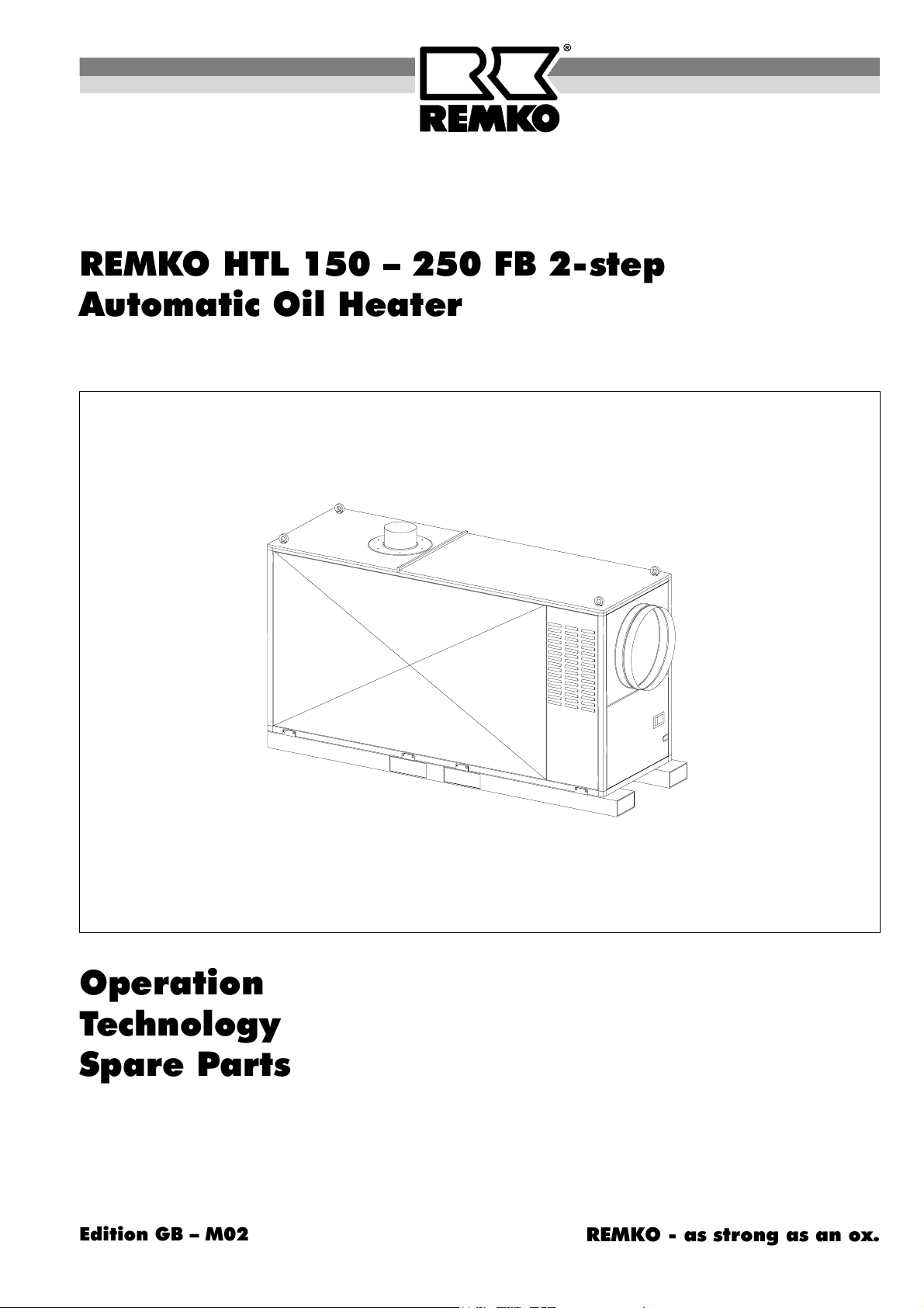
REMKO HTL 150 – 250 FB 2-step
Automatic Oil Heater
Operation
Technology
Spare Parts
Edition GB – M02
REMKO - as strong as an ox.
Page 2

Page 3
Operating instructions
Make sure to read these instructions carefully before starting/using the unit!
Our guarantee will become void when the unit supplied by us is used and installed
for inadequate purposes, or maintained incorrectly, etc.,
or if it is changed without our prior consent.
Automatic Oil Heater
Contents page
Safety Hints 4
Safety Device 4
Before Starting 5
Starting 5
Shut Down 6
Troubleshooting Instructions 6
Maintenance 7
Always keep these operating instructions near or on the device!
G
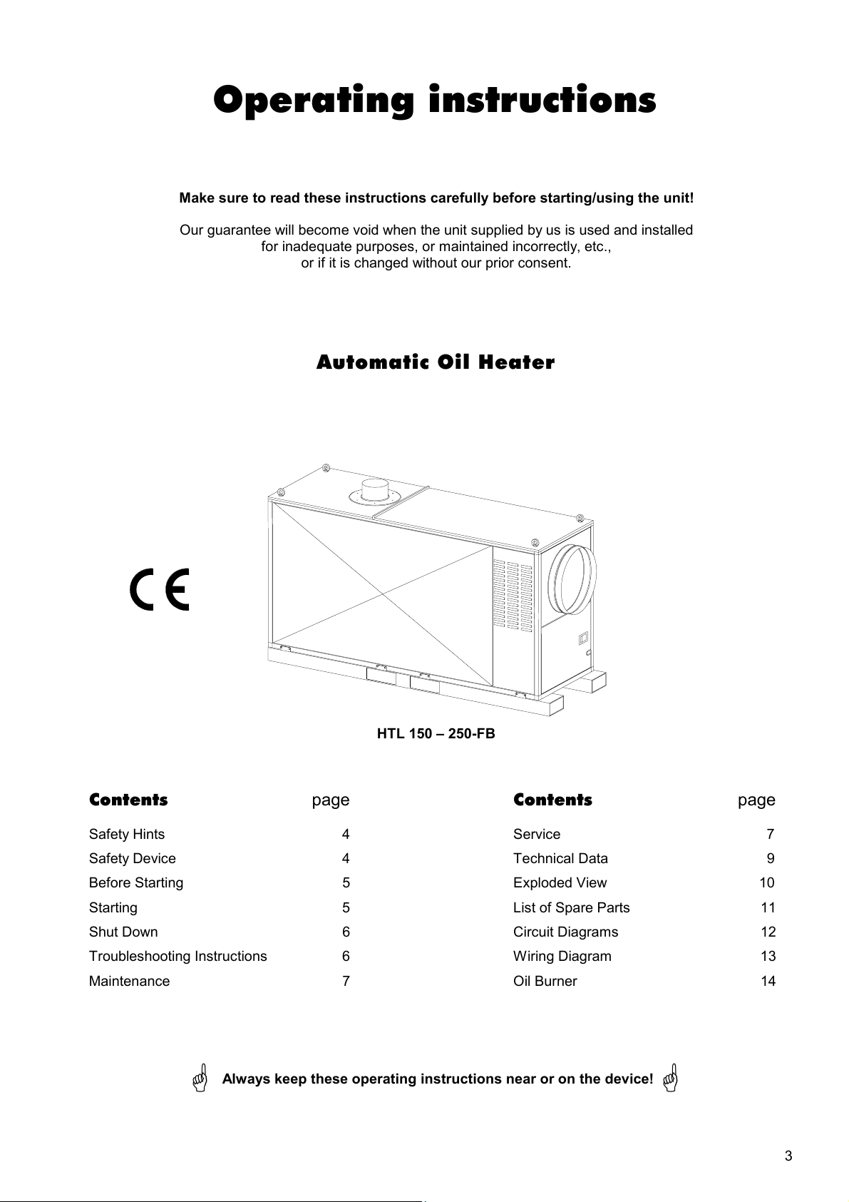
HTL 150 – 250-FB
Contents page
Service 7
Technical Data 9
Exploded View 10
List of Spare Parts 11
Circuit Diagrams 12
Wiring Diagram 13
Oil Burner 14
G
3
Page 4
Safety Hints
When using this unit make sure always to observe
the applicable building- and fire-protection regula-
tions as well as the rules of the trade co-operative
association.
à The unit may be operated only by those persons who
have been instructed accordingly.
à The unit is to be installed and operated in such a
way as to ensure that the employees are not endan-
gered by waste gases and radiation heat and that no
fire can break out.
à The unit may only be installed and operated in
rooms, when the air-rate fed to the unit is sufficient
for combustion.
à Mobile fuel reservoirs may be installed only when the
technical rules for combustible liquids “TRBF 210
and 280” are observed.
à Units without waste gas pipes my be operated only
in well aerated rooms.
Safety Device
Triple combination control according to DIN 3440
The device has 3 functions:
– Fan Control (TR)
– Burner Temperature Monitor (TW)
– Safety Temperature Limiter (STB)
Fan Control (TR)
The tripping point is set with the adjusting lever (fan).
Rated value approx. 35 to 40°C.
Burner Temperature Monitor (TW)
The tripping point is set with the adjusting lever (burner)
Rated value approx. 85 to 90°C
Safety Temperature Limiter (STB)
The tripping point is fixed according to DIN 3440.
After tripping, a burner restart is prevented.
The reset button is operated from outside.
à Persons are not allowed to stay permanently in the
room where the unit has been installed. Relevant
prohibition signs are to be fastened to the entrances.
à The unit is to be installed only on a non-combustible
ground.
à The unit may not be installed and operated in inflam-
mable and explosive surroundings.
à A safety zone of 1.5 m around the unit and a mini-
mum distance of 3 m at the unit’s waste gas opening
are to be observed, even regarding non-combustible
objects.
à The protective air suction lattice is always to be kept
free from dirt and loose objects.
à Make sure not to introduce foreign matters into the
unit.
à Make sure not to expose the unit to direct water jets.
à All electric cables outside the unit are to be protected
from damage (e.g. caused by animals, etc.).
Make sure always to pull the mains plug out of
the mains socket when maintenance and repairs
G
are carried out.
It is not allowed to bridge or to block safety
G
facilities
An operation or use other than that indicated in
these operating instructions is prohibited!
In case of non-observation we will not be held
G
responsible and our guarantee will become
void.
Before a reset, check the operating conditions of
the device to ensure that the STB-temperature is
G
not exceeded again.
Notes to the Safety Temperature Limiter (STB).
The device is equipped with a sensor monitoring feature
and is cold-resistant down to -20°C; below -20°C the de-
vice switches off; when the temperature rises above this
temperature, it switches on again.
When the sensor or the capillary tube is damaged, or
when an overtemperature of approximately 220°C is
reached, the filling medium is emptied and the device
performs a safety switch-off operation.
The device is no longer operable and must be replaced.
à When the safety facility has to be replaced, take care
not to damage or excessively bend the capillary
tubes
à Use only the original REMKO spare part.
à Do not bend the sensor spirals near to solder points.
à When mounting, the sensor spirals may not be dam-
aged or bended sharply edged.
à The sensors must be fixed in the mounting brackets
provided by the factory.
à The sensors must always be free from dust and dirt.
4
Page 5
Before Starting
Prior to starting, the unit is to be checked to make sure
that there are no visible defects on the control and
safety devices, that the unit has been installed correctly
and that it has been properly connected to the mains.
Installation requirements
à Install unit in a stable position.
à Make sure that air is supplied for combustion.
à Make sure that the air can be sucked in and be ex-
hausted freely.
à Avoid overpressure and underpressure in the room
where the unit has been installed.
à The waste gas values of the burner are to be
checked and adjusted properly by authorised experts
in accordance with the local conditions.
Power supply
à Any additional clauses of the relevant building regu-
lations and technical rules for combustible liquids
(TRBF 210 and 280) are to be observed.
à Only use clean fuel oil EL and diesel, respectively.
à Make sure that enough fuel is supplied.
à A sufficient quantity of free-flowing fuel oil must be
available even with low outside temperatures.
Paraffine formation can start even at a temperature
of 5° C. Adequate measures are to be taken to
G
avoid this.
à Connecting cable extensions may be laid exclusively
by authorised electricians based on the unit capacity,
cable length and taking the local terms of use into
account.
à The connection to the mains of the units is to be car-
ried out in accordance with the VDE 0100 regula-
tions to a special supply point with protection device
against faulty current.
Hot air distribution
The unit is equipped with a high-duty radial fan. It is suit-
able for selective and effective transportation of
warmed-up air for long distances.
Air is preferably distributed through pipings or special
hot air and sheet hoses, respectively. Hot air may be
distributed only in accordance with the fan capacity of
the units concerned.
The possible hose/pipe lengths depend on the resis-
tance on the air side of the used air ducts.
Please observe the following instructions when hot air
hoses are to be fitted:
à Please use exclusively those hot air hoses
(accessories) which have been approved by our
company.
à The inside overlappings on the seams of the hot air
hoses must run with the air current direction.
à Make sure that the hoses and pipes, respectively,
are safely fastened to the unit’s outgoing air connec-
tion piece.
à The pipes and hoses may not have sharp kinks and
bends in order to avoid heat accumulation.
à In the case of increased suction temperatures or re-
sistance on the unit’s outgoing air side, the burner
can be switched off by the temperature controller
(TW) during the heating operation for a short time.
à When the temperature has fallen the burner is re-
started automatically.
While the unit is operating, frequent startings of
G
the burner should be avoided.
When the temperature is too high on the unit’s out-
going air side, the heating-operation is interrupted
G
automatically for a longer period by the STB!
Starting
Make sure to charge a person with the operation and
supervision of the unit who has been instructed suffi-
ciently regarding the handlings concerned.
Starting of device
1. Open lock door at back of device.
2. Reassure that the operating switch (S1) in switch-
box is put into position „0“ (= OFF).
3. Place the room-thermostat in a suitable place.
The thermostat-feeler may not be exposed directly to
the hot air current.
4. Connect thermostat plug with thermostat socket.
5. Connect unit to a suitable and fused mains socket.
Control lamps for phases and neutral conductor L1,
L2, L3 and N must light up now.
Heating operation
1. Open all shut-off devices of the fuel supply.
2. Preselect desired room temperature on the room
thermostat.
The temperature set must be higher than the room
temperature.
3. Put the operating switch in switch-box into position
„1“ (= heating).
4. Please notice: when the room temperature level is
too low, the burner switches on automatically. The air
supply fan does not switch on until the set tempera-
ture of the heat-exchanger has been reached.
The control lamps for burner and fan must light up
now.
5. Close the door in order to protect the device against
unauthorised actions.
The unit runs fully automatically now with the preselected
temperature.
5
Page 6
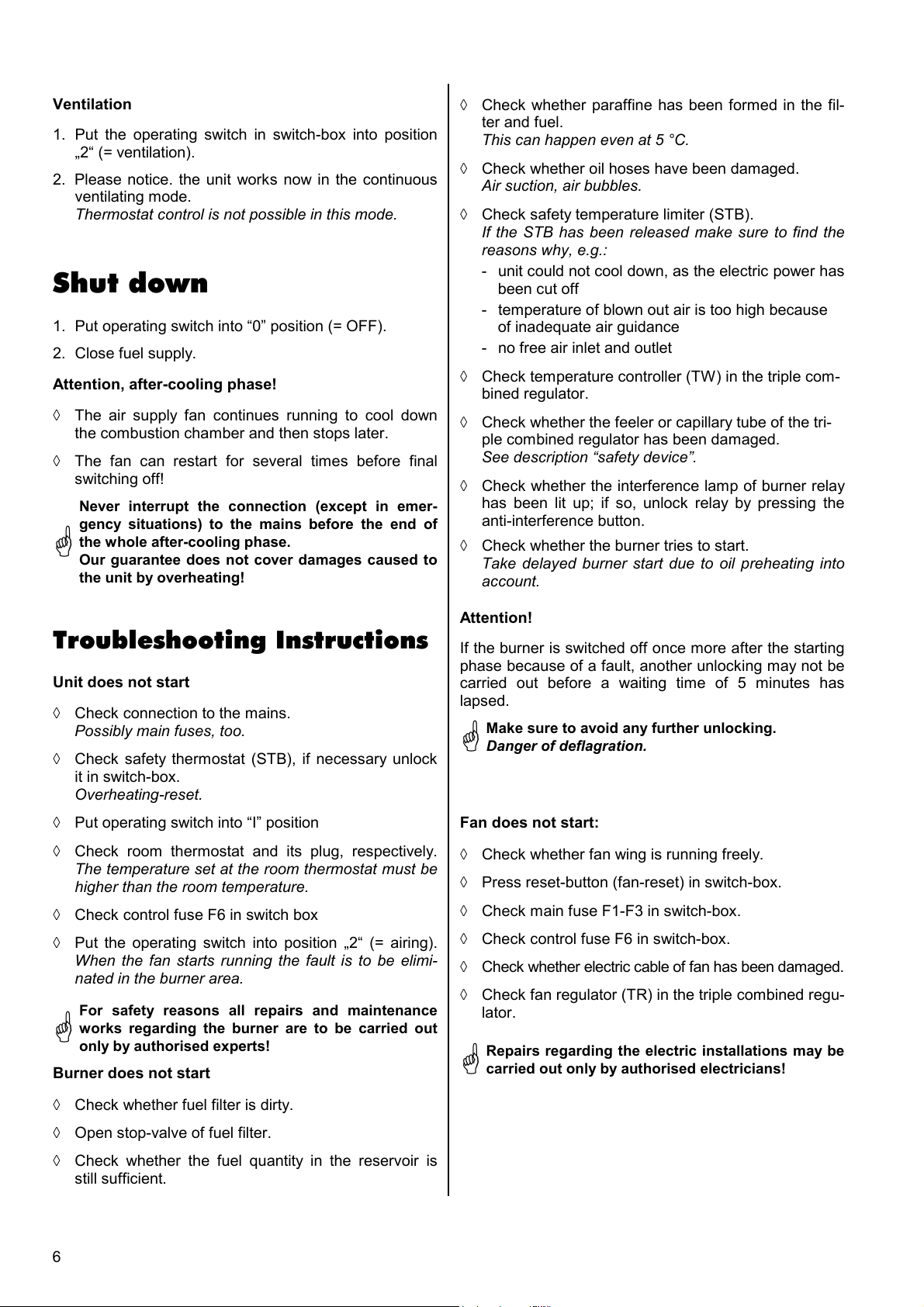
Ventilation
1. Put the operating switch in switch-box into position
„2“ (= ventilation).
2. Please notice. the unit works now in the continuous
ventilating mode.
Thermostat control is not possible in this mode.
Shut down
1. Put operating switch into “0” position (= OFF).
2. Close fuel supply.
Attention, after-cooling phase!
à The air supply fan continues running to cool down
the combustion chamber and then stops later.
à The fan can restart for several times before final
switching off!
Never interrupt the connection (except in emer-
gency situations) to the mains before the end of
the whole after-cooling phase.
G
Our guarantee does not cover damages caused to
the unit by overheating!
à Check whether paraffine has been formed in the fil-
ter and fuel.
This can happen even at 5 °C.
à Check whether oil hoses have been damaged.
Air suction, air bubbles.
à Check safety temperature limiter (STB).
If the STB has been released make sure to find the
reasons why, e.g.:
- unit could not cool down, as the electric power has
been cut off
- temperature of blown out air is too high because
of inadequate air guidance
- no free air inlet and outlet
à Check temperature controller (TW) in the triple com-
bined regulator.
à Check whether the feeler or capillary tube of the tri-
ple combined regulator has been damaged.
See description “safety device”.
à Check whether the interference lamp of burner relay
has been lit up; if so, unlock relay by pressing the
anti-interference button.
à Check whether the burner tries to start.
Take delayed burner start due to oil preheating into
account.
Troubleshooting Instructions
Unit does not start
à Check connection to the mains.
Possibly main fuses, too.
à Check safety thermostat (STB), if necessary unlock
it in switch-box.
Overheating-reset.
à Put operating switch into “I” position
à Check room thermostat and its plug, respectively.
The temperature set at the room thermostat must be
higher than the room temperature.
à Check control fuse F6 in switch box
à Put the operating switch into position „2“ (= airing).
When the fan starts running the fault is to be elimi-
nated in the burner area.
For safety reasons all repairs and maintenance
works regarding the burner are to be carried out
G
only by authorised experts!
Burner does not start
Attention!
If the burner is switched off once more after the starting
phase because of a fault, another unlocking may not be
carried out before a waiting time of 5 minutes has
lapsed.
Make sure to avoid any further unlocking.
Danger of deflagration.
G
Fan does not start:
à Check whether fan wing is running freely.
à Press reset-button (fan-reset) in switch-box.
à Check main fuse F1-F3 in switch-box.
à Check control fuse F6 in switch-box.
à Check whether electric cable of fan has been damaged.
à Check fan regulator (TR) in the triple combined regu-
lator.
Repairs regarding the electric installations may be
G
carried out only by authorised electricians!
à Check whether fuel filter is dirty.
à Open stop-valve of fuel filter.
à Check whether the fuel quantity in the reservoir is
still sufficient.
6
Page 7
Maintenance
The unit is to be maintained regularly whereby some
fundamental rules are to be observed to ensure a long
service life and trouble-free operation.
Use a clean slightly humid cloth for cleaning and wiping
the dirt off the surface. In case of obstinate dirt only suit-
able cleaning agents should be used.
Prior to starting any work make sure to pull
G
the mains plug out of the mains socket!
à The unit is to be kept free from dust and other de-
posits and is to be cleaned only with a dry or humid
cloth.
Do not use water jet.
Service
The complete unit, including heat exchanger, combus-
tion chamber and oil burner is to be cleaned from dust
and dirt after every heating period, or even earlier, de-
pending on the operational conditions.
Expendable parts, such as flue gas suppressors, gas-
kets, oil filter inserts, and oil nozzles are to be checked
and replaced, if necessary.
Fuse
protection
32 A
Cut unit from the mains!
(Remove main-plug from the socket!)
à Do not use any aggressive cleaning agents or those
which are harmful or environmentally unfriendly.
à Do not use cleaning agents which contain solvents.
à Use only clean fuel oil EL and diesel, respectively.
Make sure to avoid paraffine formation.
à Check oil filters regularly and replace dirty filters.
à Check whether the unit is free from mechanical dam-
age.
If not, replace faulty parts.
à Check fan wings and combustion chamber with heat
exchanger in regular intervals and clean them when
they are dirty.
à Check oil tank regularly and clean it when necessary
to remove dirt and foreign matters.
à Make sure that the waste gas and combustion air
can be always evacuated properly.
à Check safety devices regularly.
à The unit is to be maintained and cleaned in regular
intervals.
à Keep feelers of triple combination control always free
from dust and dirt.
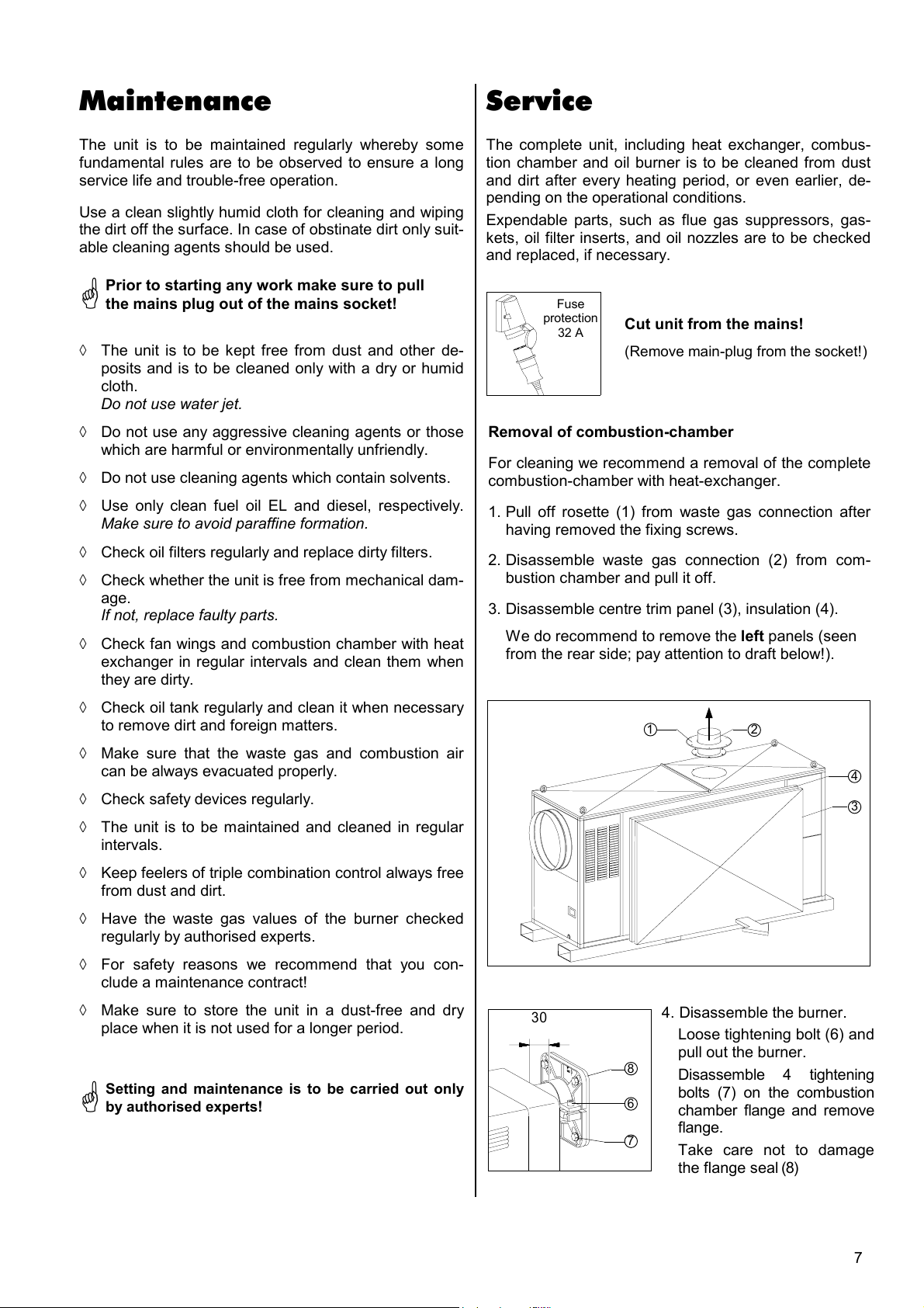
Removal of combustion-chamber
For cleaning we recommend a removal of the complete
combustion-chamber with heat-exchanger.
1. Pull off rosette (1) from waste gas connection after
having removed the fixing screws.
2. Disassemble waste gas connection (2) from com-
bustion chamber and pull it off.
3. Disassemble centre trim panel (3), insulation (4).
We do recommend to remove the left panels (seen
from the rear side; pay attention to draft below!).
1
2
4
3
à Have the waste gas values of the burner checked
regularly by authorised experts.
à For safety reasons we recommend that you con-
clude a maintenance contract!
à Make sure to store the unit in a dust-free and dry
place when it is not used for a longer period.
Setting and maintenance is to be carried out only
G
by authorised experts!
30
4. Disassemble the burner.
Loose tightening bolt (6) and
8
6
7
pull out the burner.
Disassemble 4 tightening
bolts (7) on the combustion
chamber flange and remove
flange.
Take care not to damage
the flange seal (8)
7
Page 8
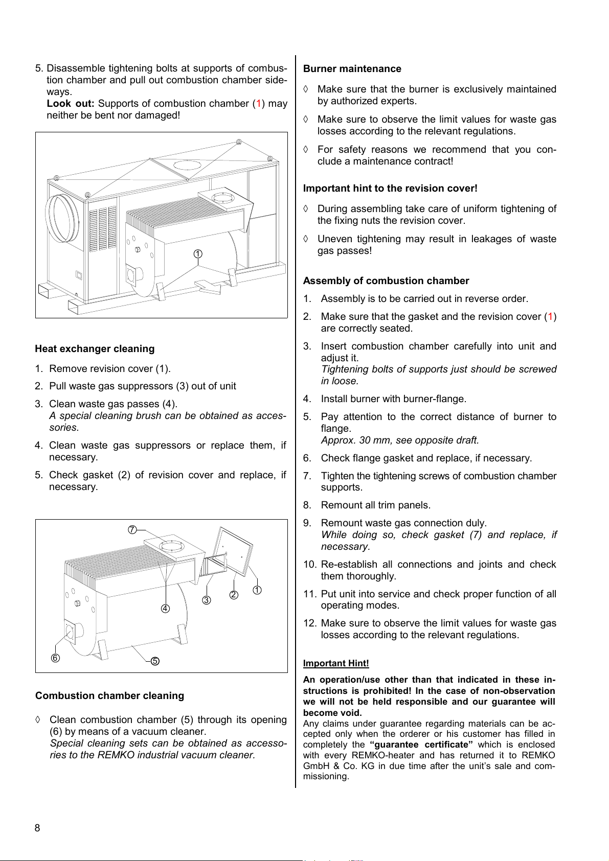
5. Disassemble tightening bolts at supports of combus-
tion chamber and pull out combustion chamber side-
ways.
Look out: Supports of combustion chamber (
1) may
neither be bent nor damaged!
1
Burner maintenance
à Make sure that the burner is exclusively maintained
by authorized experts.
à Make sure to observe the limit values for waste gas
losses according to the relevant regulations.
à For safety reasons we recommend that you con-
clude a maintenance contract!
Important hint to the revision cover!
à During assembling take care of uniform tightening of
the fixing nuts the revision cover.
à Uneven tightening may result in leakages of waste
gas passes!
Assembly of combustion chamber
1. Assembly is to be carried out in reverse order.
2. Make sure that the gasket and the revision cover (1)
are correctly seated.
Heat exchanger cleaning
1. Remove revision cover (1).
2. Pull waste gas suppressors (3) out of unit
3. Clean waste gas passes (4).
A special cleaning brush can be obtained as acces-
sories.
4. Clean waste gas suppressors or replace them, if
necessary.
5. Check gasket (2) of revision cover and replace, if
necessary.
7
1
2
4
3
3. Insert combustion chamber carefully into unit and
adjust it.
Tightening bolts of supports just should be screwed
in loose.
4. Install burner with burner-flange.
5. Pay attention to the correct distance of burner to
flange.
Approx. 30 mm, see opposite draft.
6. Check flange gasket and replace, if necessary.
7. Tighten the tightening screws of combustion chamber
supports.
8. Remount all trim panels.
9. Remount waste gas connection duly.
While doing so, check gasket (7) and replace, if
necessary.
10. Re-establish all connections and joints and check
them thoroughly.
11. Put unit into service and check proper function of all
operating modes.
12. Make sure to observe the limit values for waste gas
losses according to the relevant regulations.
6
5
Combustion chamber cleaning
à Clean combustion chamber (5) through its opening
(6) by means of a vacuum cleaner.
Special cleaning sets can be obtained as accesso-
ries to the REMKO industrial vacuum cleaner.
8
Important Hint!
An operation/use other than that indicated in these in-
structions is prohibited! In the case of non-observation
we will not be held responsible and our guarantee will
become void.
Any claims under guarantee regarding materials can be ac-
cepted only when the orderer or his customer has filled in
completely the “guarantee certificate” which is enclosed
with every REMKO-heater and has returned it to REMKO
GmbH & Co. KG in due time after the unit’s sale and com-
missioning.
Page 9
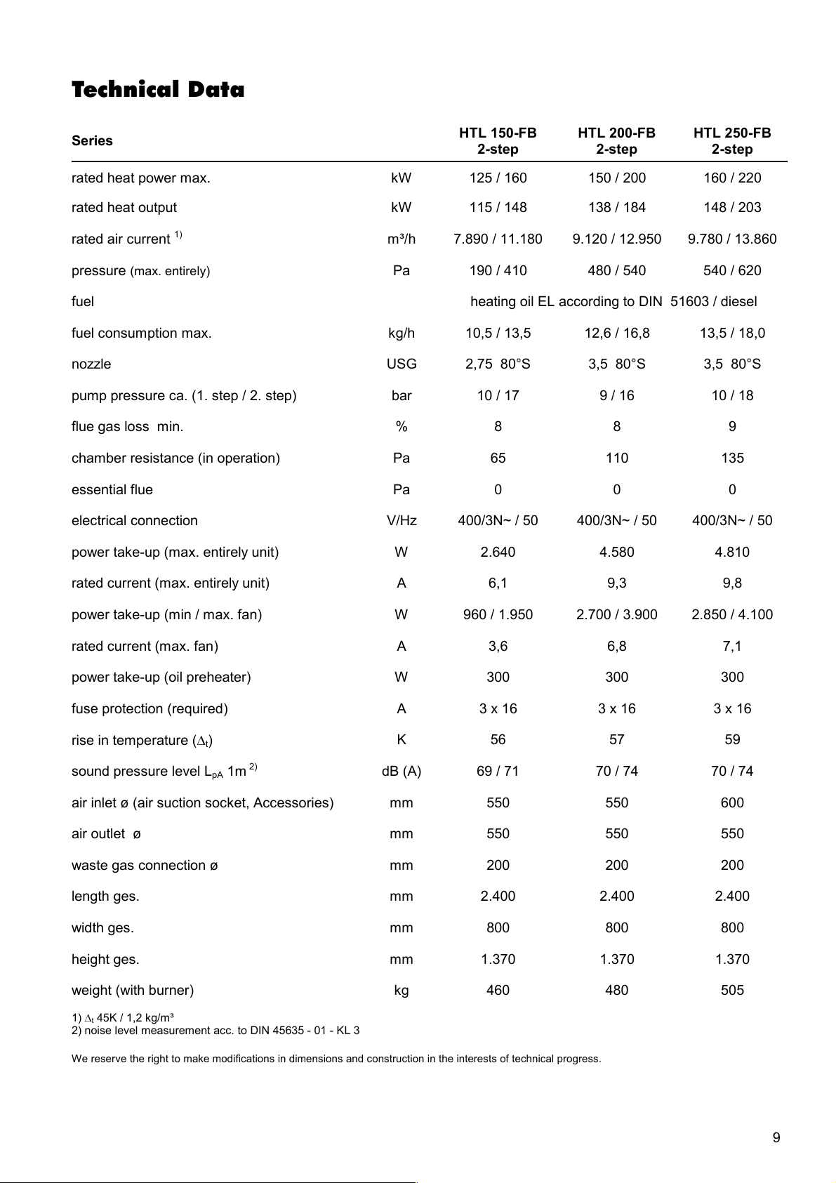
Technical Data
Series
HTL 150-FB
2-step
HTL 200-FB
2-step
HTL 250-FB
2-step
rated heat power max. kW 125 / 160 150 / 200 160 / 220
rated heat output kW 115 / 148 138 / 184 148 / 203
rated air current 1) m³/h 7.890 / 11.180 9.120 / 12.950 9.780 / 13.860
pressure (max. entirely) Pa 190 / 410 480 / 540 540 / 620
fuel heating oil EL according to DIN 51603 / diesel
fuel consumption max. kg/h 10,5 / 13,5 12,6 / 16,8 13,5 / 18,0
nozzle USG 2,75 80°S 3,5 80°S 3,5 80°S
pump pressure ca. (1. step / 2. step) bar 10 / 17 9 / 16 10 / 18
flue gas loss min. % 8 8 9
chamber resistance (in operation) Pa 65 110 135
essential flue Pa 0 0 0
electrical connection V/Hz 400/3N~ / 50 400/3N~ / 50 400/3N~ / 50
power take-up (max. entirely unit) W 2.640 4.580 4.810
rated current (max. entirely unit) A 6,1 9,3 9,8
power take-up (min / max. fan) W 960 / 1.950 2.700 / 3.900 2.850 / 4.100
rated current (max. fan) A 3,6 6,8 7,1
power take-up (oil preheater) W 300 300 300
fuse protection (required) A 3 x 16 3 x 16 3 x 16
rise in temperature (Dt)
sound pressure level LpA 1m
2)
dB (A) 69 / 71 70 / 74 70 / 74
K 56 57 59
air inlet ø (air suction socket, Accessories) mm 550 550 600
air outlet ø mm 550 550 550
waste gas connection ø mm 200 200 200
length ges. mm 2.400 2.400 2.400
width ges. mm 800 800 800
height ges. mm 1.370 1.370 1.370
weight (with burner) kg 460 480 505
1) Dt 45K / 1,2 kg/m³
2) noise level measurement acc. to DIN 45635 - 01 - KL 3
We reserve the right to make modifications in dimensions and construction in the interests of technical progress.
9
Page 10
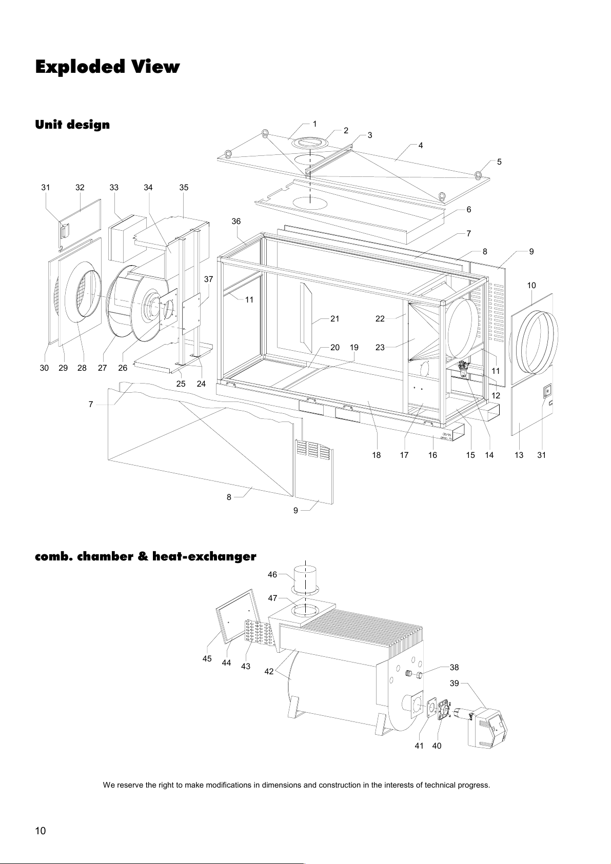
Exploded View
Unit design
31 32 33 34 35
30 29 28 27 26
7
25 24
37
36
11
1
21 22
20 19
2
3
23
4
5
6
7
8 9
10
11
12
8
comb. chamber & heat-exchanger
45
44
43
42
46
47
13 14 15 16 17 18
31
9
38
39
40 41
10
We reserve the right to make modifications in dimensions and construction in the interests of technical progress.
Page 11
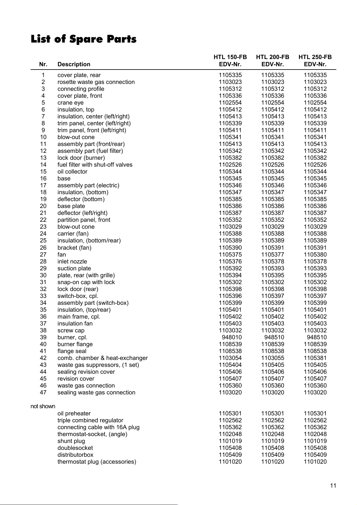
List of Spare Parts
HTL 150-FB
Nr. Description
1 cover plate, rear 1105335 1105335 1105335
2 rosette waste gas connection 1103023 1103023 1103023
3 connecting profile 1105312 1105312 1105312
4 cover plate, front 1105336 1105336 1105336
5 crane eye 1102554 1102554 1102554
6 insulation, top 1105412 1105412 1105412
7 insulation, center (left/right) 1105413 1105413 1105413
8 trim panel, center (left/right) 1105339 1105339 1105339
9 trim panel, front (left/right) 1105411 1105411 1105411
10 blow-out cone 1105341 1105341 1105341
11 assembly part (front/rear) 1105413 1105413 1105413
12 assembly part (fuel filter) 1105342 1105342 1105342
13 lock door (burner) 1105382 1105382 1105382
14 fuel filter with shut-off valves 1102526 1102526 1102526
15 oil collector 1105344 1105344 1105344
16 base 1105345 1105345 1105345
17 assembly part (electric) 1105346 1105346 1105346
18 insulation, (bottom) 1105347 1105347 1105347
19 deflector (bottom) 1105385 1105385 1105385
20 base plate 1105386 1105386 1105386
21 deflector (left/right) 1105387 1105387 1105387
22 partition panel, front 1105352 1105352 1105352
23 blow-out cone 1103029 1103029 1103029
24 carrier (fan) 1105388 1105388 1105388
25 insulation, (bottom/rear) 1105389 1105389 1105389
26 bracket (fan) 1105390 1105391 1105391
27 fan 1105375 1105377 1105380
28 inlet nozzle 1105376 1105378 1105378
29 suction plate 1105392 1105393 1105393
30 plate, rear (with grille) 1105394 1105395 1105395
31 snap-on cap with lock 1105302 1105302 1105302
32 lock door (rear) 1105398 1105398 1105398
33 switch-box, cpl. 1105396 1105397 1105397
34 assembly part (switch-box) 1105399 1105399 1105399
35 insulation, (top/rear) 1105401 1105401 1105401
36 main frame, cpl. 1105402 1105402 1105402
37 insulation fan 1105403 1105403 1105403
38 screw cap 1103032 1103032 1103032
39 burner, cpl. 948010 948510 948510
40 burner flange 1108539 1108539 1108539
41 flange seal 1108538 1108538 1108538
42 comb. chamber & heat-exchanger 1103054 1103055 1105381
43 waste gas suppressors, (1 set) 1105404 1105405 1105405
44 sealing revision cover 1105406 1105406 1105406
45 revision cover 1105407 1105407 1105407
46 waste gas connection 1105360 1105360 1105360
47 sealing waste gas connection 1103020 1103020 1103020
not shown
oil preheater 1105301 1105301 1105301
triple combined regulator 1102562 1102562 1102562
connecting cable with 16A plug 1105362 1105362 1105362
thermostat-socket, (angle) 1102048 1102048 1102048
shunt plug 1101019 1101019 1101019
doublesocket 1105408 1105408 1105408
distributorbox 1105409 1105409 1105409
thermostat plug (accessories) 1101020 1101020 1101020
EDV-Nr.
HTL 200-FB
EDV-Nr.
HTL 250-FB
EDV-Nr.
11
Page 12
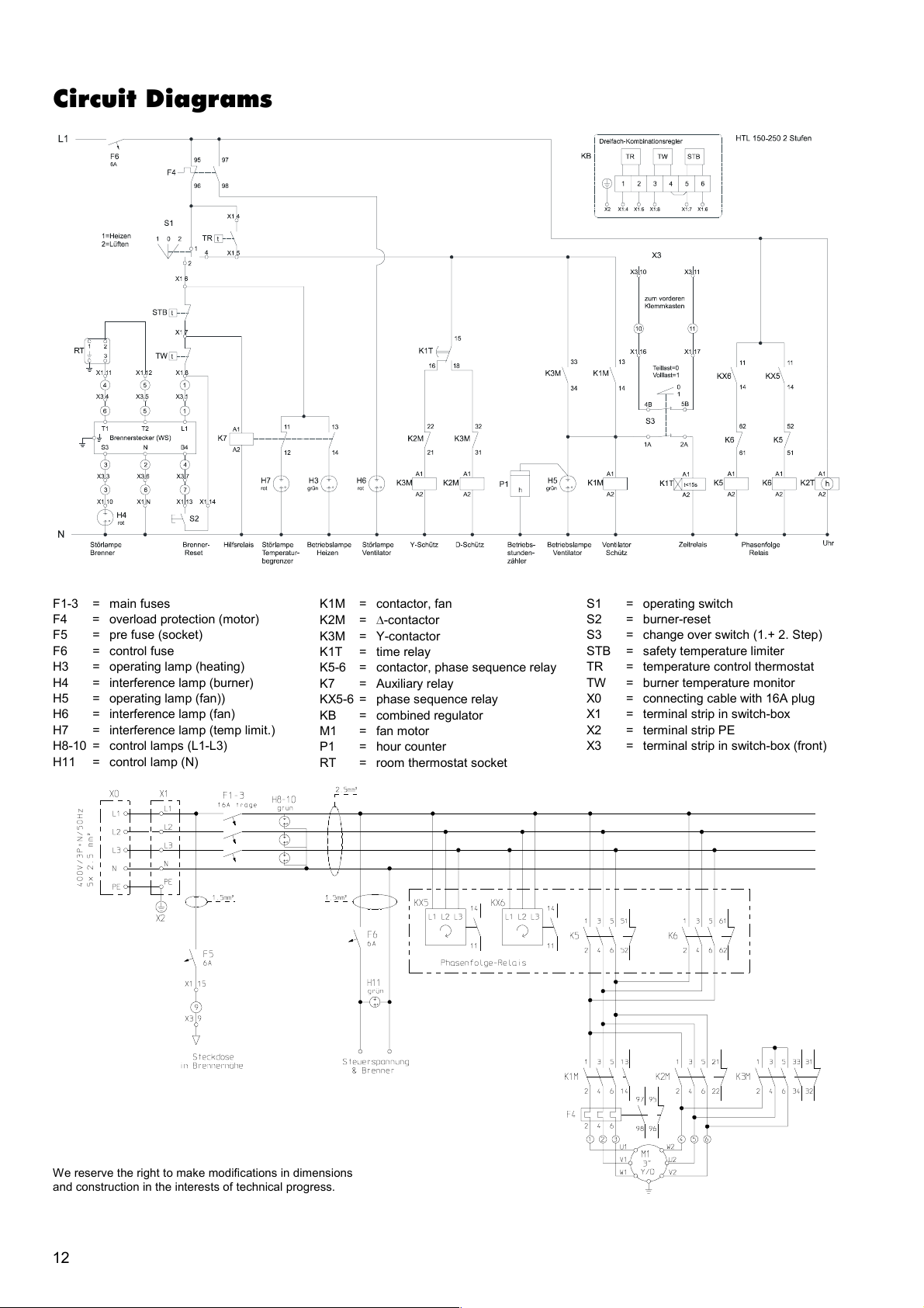
Circuit Diagrams
F1-3 = main fuses
F4 = overload protection (motor)
F5 = pre fuse (socket)
F6 = control fuse
H3 = operating lamp (heating)
H4 = interference lamp (burner)
H5 = operating lamp (fan))
H6 = interference lamp (fan)
H7 = interference lamp (temp limit.)
H8-10 = control lamps (L1-L3)
H11 = control lamp (N)
K1M = contactor, fan
K2M = D-contactor
K3M = Y-contactor
K1T = time relay
K5-6 = contactor, phase sequence relay
K7 = Auxiliary relay
KX5-6 = phase sequence relay
KB = combined regulator
M1 = fan motor
P1 = hour counter
RT = room thermostat socket
S1 = operating switch
S2 = burner-reset
S3 = change over switch (1.+ 2. Step)
STB = safety temperature limiter
TR = temperature control thermostat
TW = burner temperature monitor
X0 = connecting cable with 16A plug
X1 = terminal strip in switch-box
X2 = terminal strip PE
X3 = terminal strip in switch-box (front)
We reserve the right to make modifications in dimensions
and construction in the interests of technical progress.
12
Page 13
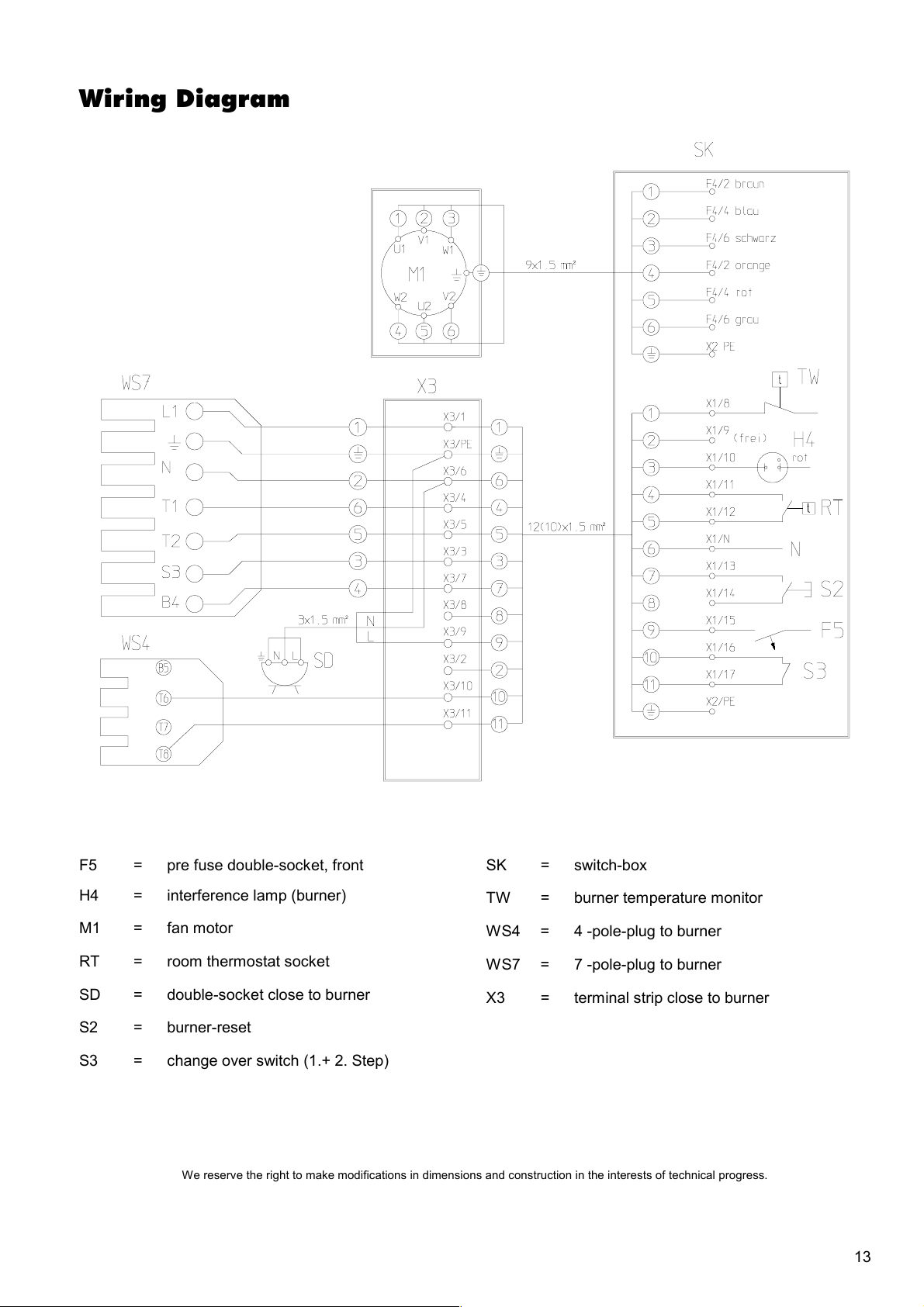
Wiring Diagram
F5 = pre fuse double-socket, front
H4 = interference lamp (burner)
M1 = fan motor
RT = room thermostat socket
SD = double-socket close to burner
S2 = burner-reset
S3 = change over switch (1.+ 2. Step)
We reserve the right to make modifications in dimensions and construction in the interests of technical progress.
SK = switch-box
TW = burner temperature monitor
WS4 = 4 -pole-plug to burner
WS7 = 7 -pole-plug to burner
X3 = terminal strip close to burner
13
Page 14
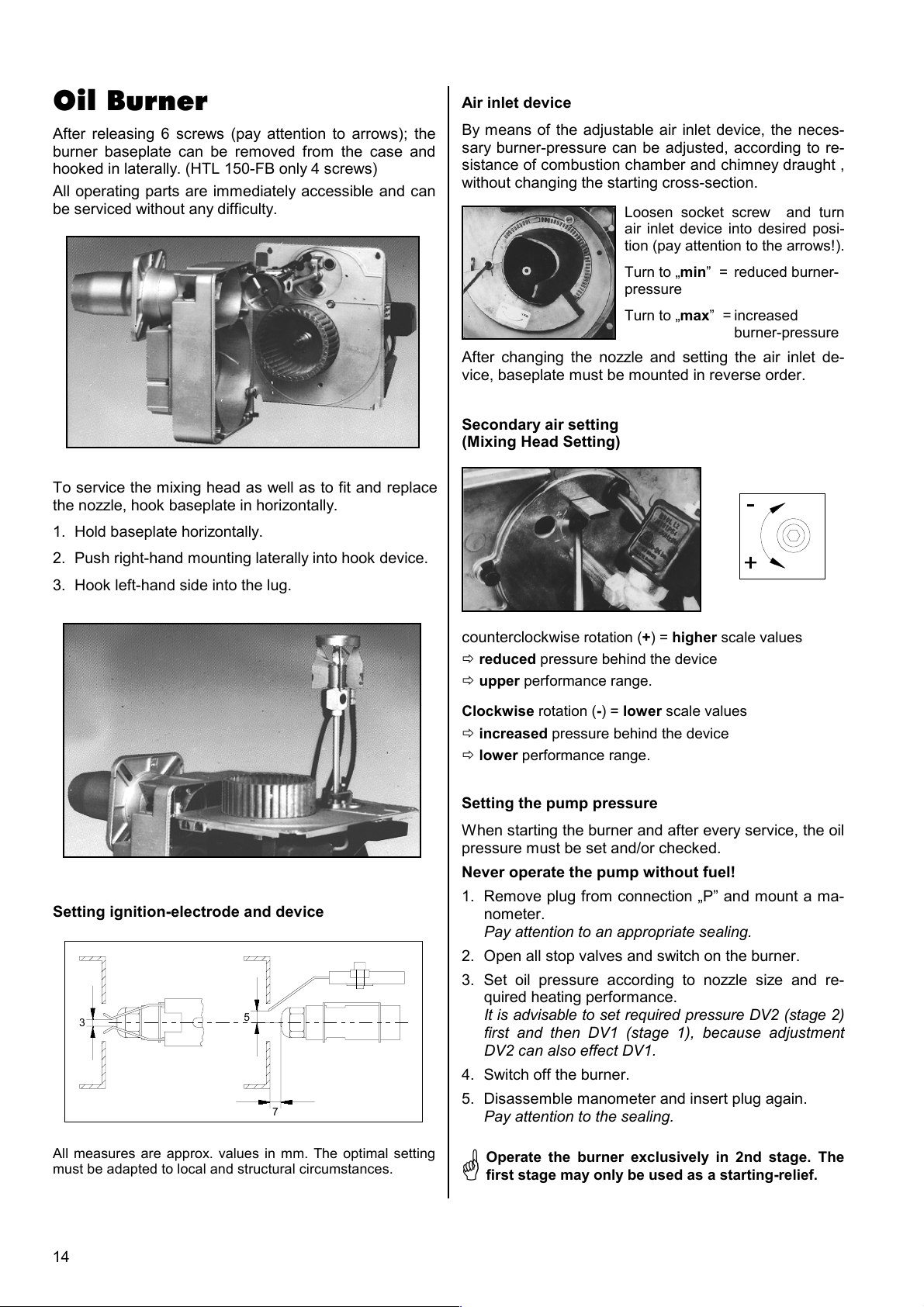
Oil Burner
After releasing 6 screws (pay attention to arrows); the
burner baseplate can be removed from the case and
hooked in laterally. (HTL 150-FB only 4 screws)
All operating parts are immediately accessible and can
be serviced without any difficulty.
To service the mixing head as well as to fit and replace
the nozzle, hook baseplate in horizontally.
1. Hold baseplate horizontally.
2. Push right-hand mounting laterally into hook device.
3. Hook left-hand side into the lug.
Air inlet device
By means of the adjustable air inlet device, the neces-
sary burner-pressure can be adjusted, according to re-
sistance of combustion chamber and chimney draught ,
without changing the starting cross-section.
Loosen socket screw and turn
air inlet device into desired posi-
tion (pay attention to the arrows!).
Turn to „min” = reduced burner-
pressure
Turn to „max” = increased
burner-pressure
After changing the nozzle and setting the air inlet de-
vice, baseplate must be mounted in reverse order.
Secondary air setting
(Mixing Head Setting)
Setting ignition-electrode and device
3
5
7
counterclockwise rotation (+) = higher scale values
ð reduced pressure behind the device
ð upper performance range.
Clockwise rotation (-) = lower scale values
ð increased pressure behind the device
ð lower performance range.
Setting the pump pressure
When starting the burner and after every service, the oil
pressure must be set and/or checked.
Never operate the pump without fuel!
1. Remove plug from connection „P” and mount a ma-
nometer.
Pay attention to an appropriate sealing.
2. Open all stop valves and switch on the burner.
3. Set oil pressure according to nozzle size and re-
quired heating performance.
It is advisable to set required pressure DV2 (stage 2)
first and then DV1 (stage 1), because adjustment
DV2 can also effect DV1.
4. Switch off the burner.
5. Disassemble manometer and insert plug again.
Pay attention to the sealing.
All measures are approx. values in mm. The optimal setting
must be adapted to local and structural circumstances.
14
Operate the burner exclusively in 2nd stage. The
first stage may only be used as a starting-relief.
G
Page 15
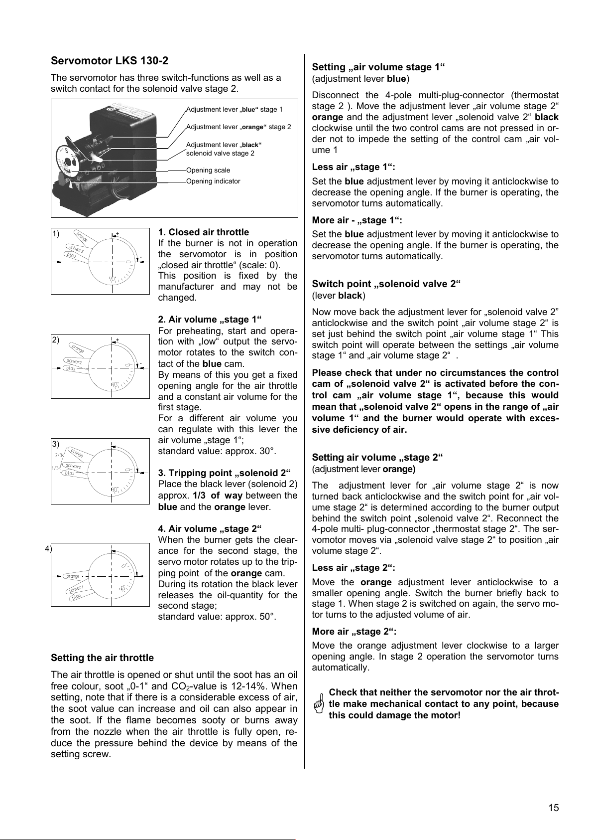
Servomotor LKS 130-2
The servomotor has three switch-functions as well as a
switch contact for the solenoid valve stage 2.
Adjustment lever „blue“ stage 1
Adjustment lever „orange“ stage 2
Adjustment lever „black“
solenoid valve stage 2
Opening scale
Opening indicator
1)
+
1. Closed air throttle
If the burner is not in operation
the servomotor is in position
-
„closed air throttle“ (scale: 0).
This position is fixed by the
manufacturer and may not be
changed.
2. Air volume „stage 1“
For preheating, start and opera-
2)
+
tion with „low“ output the servo-
motor rotates to the switch con-
-
tact of the blue cam.
By means of this you get a fixed
opening angle for the air throttle
and a constant air volume for the
first stage.
For a different air volume you
can regulate with this lever the
3)
air volume „stage 1“;
standard value: approx. 30°.
3. Tripping point „solenoid 2“
Place the black lever (solenoid 2)
approx. 1/3 of way between the
blue and the orange lever.
4. Air volume „stage 2“
When the burner gets the clear-
4)
ance for the second stage, the
servo motor rotates up to the trip-
ping point of the orange cam.
During its rotation the black lever
releases the oil-quantity for the
second stage;
standard value: approx. 50°.
Setting the air throttle
The air throttle is opened or shut until the soot has an oil
free colour, soot „0-1“ and CO
-value is 12-14%. When
2
setting, note that if there is a considerable excess of air,
the soot value can increase and oil can also appear in
the soot. If the flame becomes sooty or burns away
from the nozzle when the air throttle is fully open, re-
duce the pressure behind the device by means of the
setting screw.
Setting „air volume stage 1“
(adjustment lever blue)
Disconnect the 4-pole multi-plug-connector (thermostat
stage 2 ). Move the adjustment lever „air volume stage 2“
orange and the adjustment lever „solenoid valve 2“ black
clockwise until the two control cams are not pressed in or-
der not to impede the setting of the control cam „air vol-
ume 1
Less air „stage 1“:
Set the blue adjustment lever by moving it anticlockwise to
decrease the opening angle. If the burner is operating, the
servomotor turns automatically.
More air - „stage 1“:
Set the blue adjustment lever by moving it anticlockwise to
decrease the opening angle. If the burner is operating, the
servomotor turns automatically.
Switch point „solenoid valve 2“
(lever black)
Now move back the adjustment lever for „solenoid valve 2”
anticlockwise and the switch point „air volume stage 2“ is
set just behind the switch point „air volume stage 1“ This
switch point will operate between the settings „air volume
stage 1“ and „air volume stage 2“ .
Please check that under no circumstances the control
cam of „solenoid valve 2“ is activated before the con-
trol cam „air volume stage 1“, because this would
mean that „solenoid valve 2“ opens in the range of „air
volume 1“ and the burner would operate with exces-
sive deficiency of air.
Setting air volume „stage 2“
(adjustment lever orange)
The adjustment lever for „air volume stage 2“ is now
turned back anticlockwise and the switch point for „air vol-
ume stage 2“ is determined according to the burner output
behind the switch point „solenoid valve 2“. Reconnect the
4-pole multi- plug-connector „thermostat stage 2“. The ser-
vomotor moves via „solenoid valve stage 2“ to position „air
volume stage 2“.
Less air „stage 2“:
Move the orange adjustment lever anticlockwise to a
smaller opening angle. Switch the burner briefly back to
stage 1. When stage 2 is switched on again, the servo mo-
tor turns to the adjusted volume of air.
More air „stage 2“:
Move the orange adjustment lever clockwise to a larger
opening angle. In stage 2 operation the servomotor turns
automatically.
Check that neither the servomotor nor the air throt-
tle make mechanical contact to any point, because
G
this could damage the motor!
15
Page 16
REMKO GmbH & Co. KG
Klima- und Wärmetechnik
D-32791 Lage • Im Seelenkamp 12
D-32777 Lage • PO Box 1827
Phone +49 (5232) 606 - 0
Fax +49 (5232) 606260
 Loading...