

Page 1
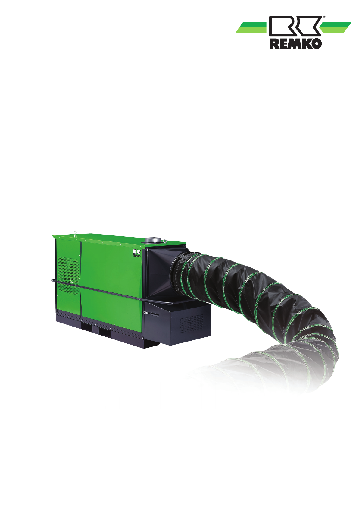
REMKO HTL 80
HTL 170
Oil heating systems
Operation · Technology · Replacement parts
Edition GB - D09
Page 2

Page 3
Contents
Safety notes
Unit description
Installation instructions
Safety device
Exhaust ducting
Before commissioning
Commissioning
Shutdown
Care and maintenance
Troubleshooting
Intended use
Customer service and guarantee
Environmental protection and recycling
4
5
6
7
8
9-10
10-11
11
12-14
14
15
15
15
Exploded view of the unit
Spare parts list
Electrical wiring diagram HTL 80
Electrical wiring diagram HTL 170
Commissioning fan oil burner
20-21
Maintenance protocol
Technical data
Carefully read this operating manual prior to commissioning /using
the unit!
This operating manual is a translation of the German original.
16
17
18
19
22
23
Made by REMKO
These instructions are an integral part of the unit and must always be
kept in the vicinity of the installation location or on the unit itself.
Subject to modifications; no liability accepted for errors or misprints!
3
Page 4

REMKO HTL 80/170
Safety notes
Always observe the respective local building code and fire prevention
guidelines as well as the guidelines of the accident prevention and
insurance associations as a basic rule when using the unit.
■
The units may only be operated
by persons that have been
extensively instructed in
the operation of the equipment
■
The units must be installed in
a stable position.
■
The units must be installed and
operated in such a way that
personnel are not endangered
by exhaust, warm air and
radiant heat and no fires may
occur
■
The units must then only
be operated in areas where
the units can be supplied with
an adequate amount of air
for the combustion
■
If the units are being operated
without exhaust gas routing
then they may only be operated
in well ventilated areas.
Under such circumstances
it is forbidden for personnel
to remain in these areas
for extended periods.
Appropriate prohibition
signs should be put up
at the entrances
■
A safety zone of 1.5 m should
be maintained around the units
- incl. non-combustible items
■
All electrical cables for the units
must be protected against
damage (e.g. by animals etc.)
■
The units must not be
exposed to direct jets of water,
e.g. pressure washers etc.
■
Portable fuel containers must
only be set up and used in
observance of the technical
rules for combustible liquids
"TRbF 20".
■
Any additional conditions from
the respective regional building
regulations must be observed
■
The protective grid of the unit's
intake must always be kept free
of dirt and loose objects
■
Never stick foreign objects into
the units
■
The power plug must be pulled
out of the mains socket before
the start of work on the unit as
a matter of principle
■
Safety devices may be neither
bypassed nor disabled
■
The personnel tasked with
operating the units must check
the units for visible defects
on the operating and safety
devices as well as the presence
of the protective devices
at the start of work.
■
In the case of defects that
endanger the operational safety
of the unit, it must be taken out
of service immediately.
ATTENTION
The units may never be
disconnected from the mains
prior to the completion
of the follow-up cooling phase
(except in emergencies).
NOTE
Only type-approved forced-air
oil burners in WLE design per
DIN EN 267 should be used.
■
The units may only be installed
on a level and non-combustible
surface.
■
The units may not be installed
or operated in potentially
flammable or explosive
environments
4
NOTE
For optimum operation
the units should not be
operated above an ambient
temperature of 25 °C.
Page 5

Unit description
The units are portable, directly
fired fan-assisted heaters (WLE)
with heat exchanger and exhaust
gas connections exclusively
for commercial applications.
The units are directly fired with EL
heating oil or Diesel fuel.
The units can be operated with
or without exhaust gas pipe
(depending on the conditions
on the customer's side).
They have been designed
for universal and straightforward
use.
The units must be exclusively
operated with separate typeapproved forced-air WLE-type
burners.
The units are equipped with
a noise-optimised and lowmaintenance, high performance
radial fan, a room thermostat
receptacle and a mains cable with
a 230 V shock-proof plug or HTL
170 with 400 V CEE plug.
The HTL 170 units are equipped
with a device for automatically
checking the turning direction
of the fan motor, as standard.
With factory fitted forced-air oil
burners the HTL 170 units have
integrated REMKO Multiflex oil
pre-heating fitted as standard.
With the HTL 80 this is available as
an option (EDP no. 1071411) .
The units conform
to the fundamental health
and safety requirements
of the appropriate EU stipulations
and are simple to operate.
Operating sequence
If the units are set to heating
mode, then the forced-air burner
starts automatically. In fully
automatic heating mode with
room thermostat the forced-air
burner starts only when heat is
required.
After the burner has run for a short
time the temperature controller
"TR" (target temperature ca.
40°C) switches the supply air fan
on automatically.
Warm air is blown out.
When operating with a room
thermostat this process is
repeated automatically depending
on the heat demand.
The temperature monitor "TW"
(target temperature 80 to 85°C)
monitors the internal temperature
of the unit.
After switching off the units via
the operating switch or the room
thermostats the supply air fan
runs to cool the combustion
chamber with the heat exchanger
for a certain time and then
switches off automatically.
This process may be repeated
several times if necessary,
depending on the temperature
profile.
In simple ventilating mode the unit
can be used to recirculate the air
permanently.
Thermostatic control is not possible
in this case.
Locations at which units are
used
As mobile, directly fired fanassisted heaters, the units deliver
instant heat.
They are designed exclusively
for commercial use, with and
without warm air hoses.
The units may be used
for the heating, temperature
adjustment or drying of:
■
Warehouses
■
Exhibition halls
■
Trade fairs
■
Lightweight construction halls
■
Large tents / marquees
■
Large construction sites
■
Building drying
5
Page 6

REMKO HTL 80/170
Installation instructions
The safety regulations of the accident prevention and insurance
associations, the respective regional
building regulations and the combustion appliances regulations
apply in principle to the operation
of the unit.
NOTE
Overpressure and
underpressure in
the installation area should be
avoided as this will inevitably
lead to combustion-related
v
faults.
■
Make sure that there is an ad-
equate fresh air supply appropriate to the respective forcedair burner capacity (see name
plate).
The forced-air oil burner may
need to be fitted with a separate air supply for combustion
Installation outside
Installation in closed, well
ventilated areas without
exhaust gas connection
■
The operation of the units
is permissible if the minimum
air quantity for combustion is
supplied.
■
Reliable extraction
of the combustion gases must
be guaranteed in all cases in
order to exclude impermissible
contamination of the room air
with hazardous substances.
Fresh air is fed from below.
Exhaust gases are routed
upwards.
■
It is forbidden for personnel
to remain in these areas
for extended periods.
Appropriate prohibition
signs should be put up
at the entrances
Room heating
■
The units may only be operated
for room heating with a room
thermostat (accessory)
■
The fresh air supply required
for trouble-free combustion
must be guaranteed.
It is practical to have the fresh
air supply provided by
windows and doors or through
appropriately dimensioned
openings in the outside wall
■
The exhaust gases must be fed
to the outside via the flue gas
pipes.
Safety distances
■
In order to guarantee safe
operation and maintenance
of the units, 1.5 m safety
distance should be maintained
around the unit.
■
The operation of the units
must not present a hazard or
unreasonable loading
■
The unit operator must
ensure that it is not possible
for unauthorised persons to be
able to manipulate either
the unit or the power supply.
■
The unit must be protected
from unauthorised use
■
Precipitation such as rain or
snow can be sucked in through
the supply air fan.
For this reason suitable weather
protection should be provided.
ATTENTION
The units must only be
installed in well ventilated
spaces and not in living areas
or similar recreational areas.
■
Flooring and ceilings must
be fire retardant
■
Intake and outlet diameters
must not be narrowed or
blocked with foreign objects.
6
Page 7
Safety equipment
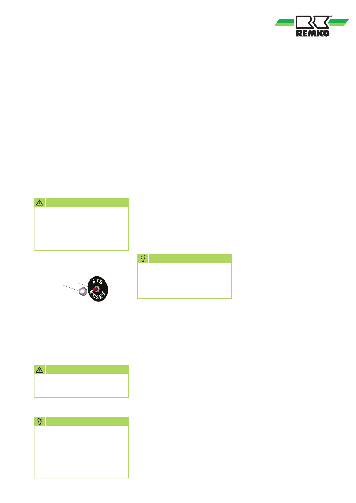
Safety temperature limiter (STB)
The heating function is
permanently interrupted by
the safety temperature limiter
(STB) in the event of the units
overheating or malfunctioning.
Manually resetting of the STB
can only be implemented after
the units have cooled down.
The resetting of the STB is
implemented by actuating
the reset button 2.
ATTENTION
If the safety temperature
limiter has been tripped then
the cause of the malfunction
should be identified and
rectified before resetting it.
Regulating device
The temperature sensor
of the controller is self-monitoring.
The probes are cold-resistant
to -25 °C.
At temperatures below -25 °C
the controller current flow will be
interrupted - if the temperature
rises above -25 °C the current flow
will be released again.
In the event of the probe or
the capillary tube being damaged,
as well as if an overtemperature
of ca. 220 °C is reached, the fill
medium will be emptied and
the safety device is permanently
triggered.
Resetting is no longer possible.
The controller is no longer fully
functional and must be replaced.
The units have the following
control or safety equipment:
Temperature controller (TR)
The temperature controller
controls the switching on and off
of the recirculating fan. The switch
point is set via the "Scale 21 60°" controller in the switching
cabinet.
Target value ca. 35 - 40 °C.
Temperature monitor (TW)
The temperature monitor limits
the unit or outlet temperature
in heating mode via the burner.
The switch point is set via
the "Scale 34 - 110°" controller
in the switching cabinet.
Target value ca. 80 - 85 °C.
1. Unscrew protective cap [1].
2
1
2. Carefully press in the reset
button [2] with a suitable tool.
3. Screw the protective cap [1]
back on again.
ATTENTION
Safety devices may be neither
bypassed nor disabled.
NOTE
NOTE
Only
"REMKO original
replacement parts"
used when replacing safety
devices.
■
Ensure that the device is fitted
properly
■
The capillary tubes must
not be kinked or bent in
the immediate vicinity
of the soldering points
■
The capillary tubes must not
be damaged or kinked during
installation
■
The probes must only be fitted
at the fastening points provided
by the factory
must be
Safety temperature limiter (STB)
The unit is permanently
switched off by the safety
temperature limiter (STB) in
the event of the unit overheating
or a temperature monitor
malfunction.
Manual resetting is required.
Automatic burner
The unit is permanently
switched off by the automatic
burner through the optical
flame monitoring in the event
of irregularities in the combustion,
the flame extinguishing, fuel
deficiencies etc.
Manual resetting is required.
In order to prevent a renewed
exceedance of the triggering
temperature the operating
conditions of the unit should
be checked before resetting
the STB.
■
The probes must always be
free of dust and dirt in order
to be sure of their correct
functioning
7
Page 8
REMKO HTL 80/170
Exhaust ducting
It is also possible to operate
the units outside or in open
rooms / halls without exhaust gas
routing.
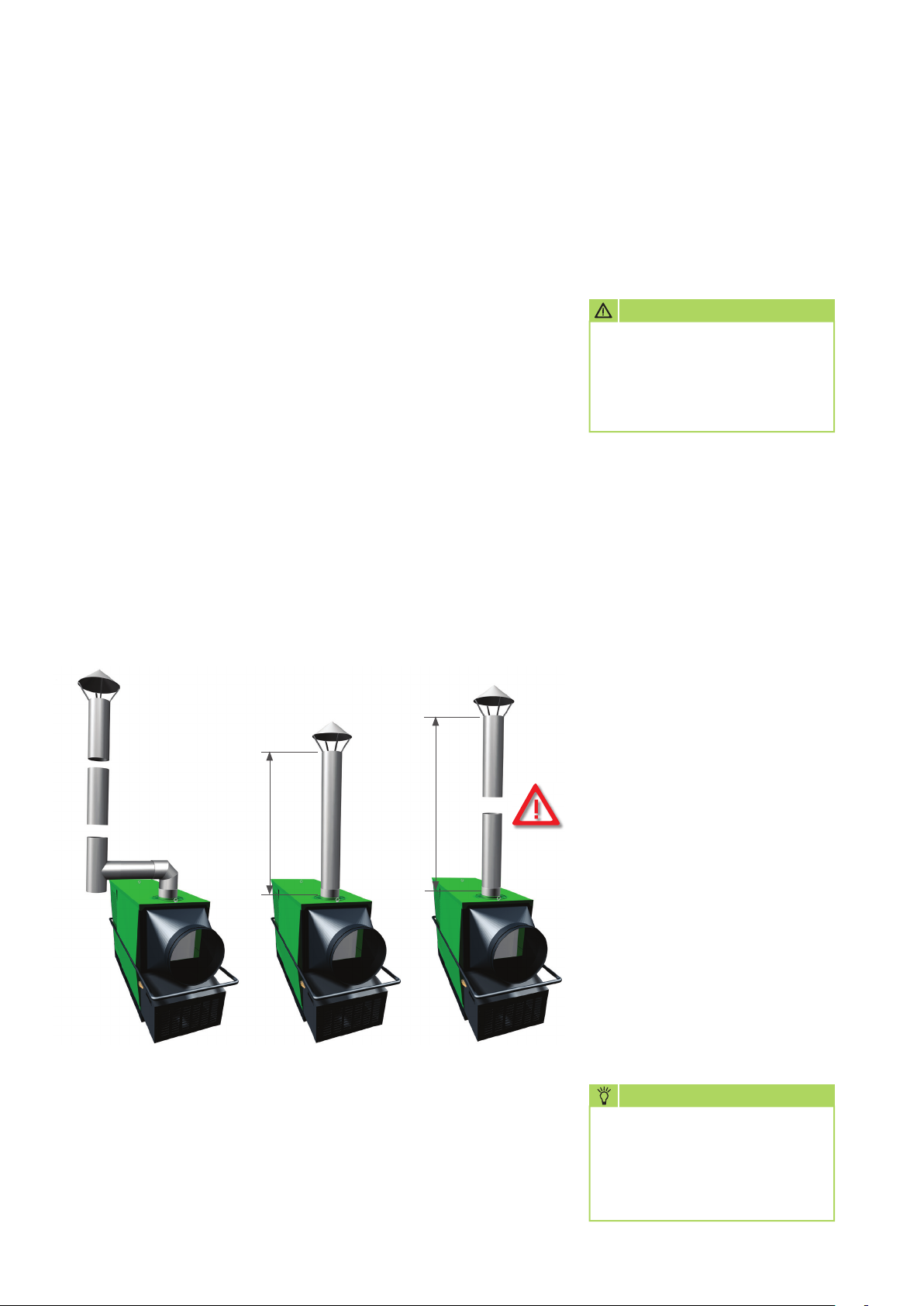
However, we recommend fi tting
a 1m exhaust gas duct with a rain
hood on top (example 2), in order
to exclude the ingress of rainwater
and dirt.
If the units are used for room
heating then the combustion
gases must be routed away,
to the outside if necessary.
■
The exhaust gas routing
must be designed such that
the thermal lift of the exhaust
gases is guaranteed at all times
■
Die The exhaust gas routing
must be designed such that
there can be no counterpressure
■
Fault-free operation is
guaranteed if the exhaust
gas routing is fi tted in a rising
arrangement and with a vertical
end pipe
■
The exhaust gas routing should
end at least above the height
of the eaves but ideally above
the height of the ridge, in order
to prevent any counter-pressure
being caused by poor weather
conditions (e.g. wind)
■
The minimum distance of 0.6 m
to combustible parts must not
be infringed
■
Exhaust gas ducting parts and
fastening materials are available
as accessories
■
All parts of the exhaust gas
routing must be reliably
fastened. Its diameter must
not be smaller than the outlet
nozzle of the unit.
ATTENTION
There must be no counter
pressure arising from incorrect
installation of exhaust
gas ducting under any
circumstances.
Notes for implementing the 1st.
BImSchV
Units that are not expected
to be operated for longer than
3 months in the same location are
not subject to any approvals or
monitoring per the 1st. BImSchV.
(§1, section 3)
✔
Example 1
Operation with
extended exhaust
gas ducting
Condensate trap
required.
Max. 1 metre
Example 2
Operation without
extended exhaust
gas ducting.
Max. 1 metre
More than 1 metre
Example 3
Impermissible
arrangement
In order to avoid the combustion
chamber being damaged due
to condensation of moisture
(condensate) in example 3,
make sure that the exhaust gas
ducting is correctly installed
with a condensate trap as shown
in example 1.
NOTE
After installing an exhaust
gas system the settings
on the burner should
be adapted to suit the new
conditions.
8
Page 9

Before commissioning
The units should be checked
for visible defects on the operating
and safety devices as well as
proper installation and correct
electrical connections before
commissioning.
It is essential that the following
points be observed:
■
The units must be installed
in a stable position
■
Ensure there is sufficient supply
of combustion air
■
Check that the inlet and outlet
are free
■
Prevent overpressure or
underpressure in the installation
area
■
Ensure that there is sufficient
fuel supply and that it complies
with the respective local
regulations
■ Only use clean EL heating oil or
Diesel fuel. Do not use Bio-Diesel!
■
The suction pipe in the base
of the tank must be fitted
with a foot valve as a matter
of principle
NOTE
After fulfilling the respective
local regulations as well as
a professional installation
of the unit, the exhaust values
for the forced-air burner must
be checked and adjusted
if necessary by authorised
specialists.
NOTE
Air feeds on the intake side
must always be implemented
by means of non-distorting
hoses/ducts (no unstable
hoses).
Air distribution
The units are equipped with a high
performance radial fan, which
has been designed to transport
the heated air efficiently and
effectively over large distances.
The distribution of the air is
preferably implemented via
ducting or special warm air or
membrane hoses.
■
Use hot air hoses approved by
us (accessories) exclusively
■
Observe the air flow direction
of the hoses with this!
The inner overlapping
on the seams of the hot
air hoses must point in
the direction of the air flow.
■
Make sure that the hose or
ducting is securely fastened
onto the unit outlet nozzle and
any connection pieces that may
be being used
■
Only suitable air distributors
or air distributors approved
by ourselves should be used
for the air distribution
NOTE
The hot air hoses must only
be used in fully extended form
and without any constrictions.
■
Enclosed spaces being heated
via hoses must not present any
overpressure
■
The forced-air burner can
be switched off briefly during
operation by the temperature
monitor (TW) in the event
of there being increased intake
temperatures or resistance
at the unit's outlet.
After the temperature drops
again the burner starts anew
automatically!
■
If the cycle intervals are too
short the length and layout
of the hot air routing should
be checked
NOTE
Cycled operation
of the forced-air burner with
run times under 5 min. should
certainly be avoided.
■
There should be no kinks or
bends in the layout of the hoses
in order to prevent hot-spots
forming.
Membrane hoses must not be
twisted
ATTENTION
If a build-up of heat should
occur then the heating
operation will be interrupted
by the STB permanently.
Suction air
Fresh air, mixed air or
circulated air operating modes
can be selected on the unit.
The following information refers
to the installation of the unit
outside the space to be heated.
Fresh air operation:
The air intake is implemented in
the factory through 2 intake grills,
right / left.
Mixed air operation:
For operation of the unit in mixed
air mode it is necessary to fit
the intake nozzles, available as
accessories.
In order to guarantee adequate air
throughput the second intake grill
must not be covered.
Circulated air operation:
For operation of the unit with
100% recirculated air it is
necessary to fit two intake nozzles,
available as accessories, in place
of the 2 factory-fitted intake grills.
9
Page 10
REMKO HTL 80/170
s
s
s
Commissioning
Paraffin formation with low
outside temperatures
Even at low outside temperatures
it is necessary to ensure that there
is an adequate supply of heating
oil that is capable of flowing.
■
Paraffin formation can start with
temperatures as high as 5 °C
■
To avoid this appropriate
preventative measures must be
implemented.
e.g. Winter-proof EL heating
oil or winter Diesel, heated oil
tank, insulated oil lines etc.
■
Note that fault-free operation
of the Multiflex oil pre-heating
can only be guaranteed if
the unit has been supplied
with electrical power for a long
period of time before starting
■
It is not possible to rectify
paraffin separation that
has already occurred with
the heating. If paraffin has
already formed it is necessary
to clean out the complete fuel
system
NOTE
Paraffin formation can start
with temperatures as high
as 5 °C. To avoid this
appropriate preventative
measures must be
implemented, e.g. winter
Diesel.
One person, who has been
adequately trained in the handling
of the unit, should be tasked with
the operation and monitoring
of the unit.
Connecting the units with
the electrical power supply
The electrical connection is made
using a built-in mains cable with
plug.
1. Move the operating
switch to the "0" (off)
position.
2.
Connect the power plug
with a properly installed and
appropriately safeguarded
mains socket
400V/3~N/50Hz .
3. Open all of the oil supply shut-off
devices.
With the initial commissioning,
air in the lines can lead to a fault
shut-down of the burner.
NOTE
The electrical connection
for the units must be made
at a separate feedpoint with
a residual current device in
accordance with VDE 0100,
Section 55.
ATTENTION
All cable extensions must only
be used in fully un-reeled or
reeled off condition.
NOTE
230V or shock-proof
Control panel
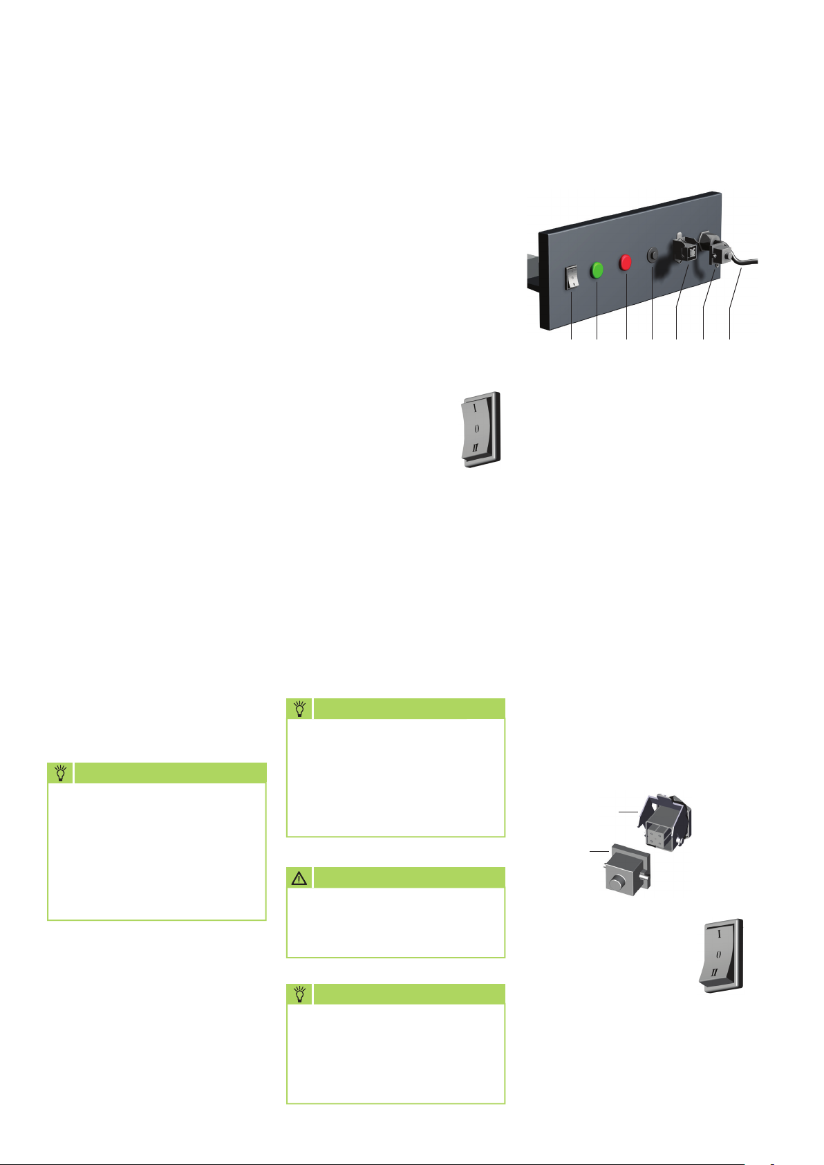
8765
1
1 = Thermostat receptacle
2 = Strapping plug
5 = Operating switch
6 = Indicator light "GREEN"
"Operation"
7 = Indicator light "RED"
"Burner fault"
8 = Reset button "Burner"
9 = Mains cable with plug
Heating without room
thermostat
The units are operating in
permanent operating mode.
1. Connect the strapping
plug supplied [2] with
the thermostat receptacle [1]
on the unit.
1
2
2. Move the operating
switch to the "I" (on)
position.
2
9
10
The 400V version of the unit
is equipped with a device
for automatically checking
the turning direction of the fan
motor, as standard.
Page 11
Shutdown
Heating with room thermostat
(Accessories)
The units operate fully
automatically and exclusively
in accordance with the room
temperature.
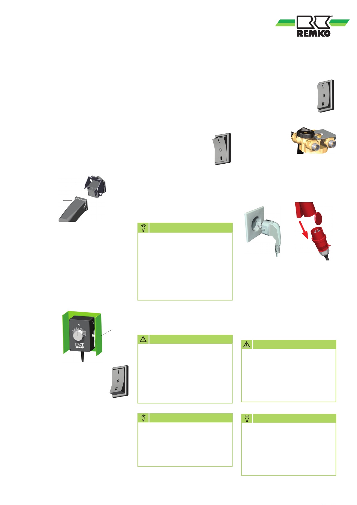
1. Pull out the strapping plug [2].
2. Connect the room thermostat
[4] plug [3] with the thermostat
receptacle [1] on the unit.
1
3
3. Place the room thermostat
[4] at a suitable location in
the room.
The thermostat sensor must not
be located directly in the warm
air flow and should also not be
placed directly on the cold floor.
4. Set the desired temperature
on the room thermostat [4].
4
5. Move the operating
switch to the "I"
(Heating) position.
Ventilate
In this switch position the supply
air fan runs permanently.
The units can be used for air
recirculation or ventilation
purposes.
1. Move the operating
switch to the "II"
(Ventilate) position.
Thermostatic control as well as
heating operation is not possible
in this operating mode.
NOTE
Indicator light "Operation"
The indicator light signals
the "Heating" operating
mode. There is no display in
the "Ventilate" operating mode
or with the room thermostat
switched off and when the STB
has been triggered.
ATTENTION
The thermal overcurrent relay
must be operated exclusively
in the "Manual resetting"
position. It is not permitted
for the relay to be able
to switch itself back on again
after the cooling down phase.
1. Move the operating
switch to the "0"
(off) position.
2. Shut off fuel
supply.
3. With longer periods of inactivity,
disconnect the units from
the mains power supply.
The supply air fan runs on to
cool the combustion chamber
and the heat exchanger and only
switches off after the cooling
down phase is complete.
The fan can switch on and run
several times before the final
shutdown.
ATTENTION
Never interrupt the power
supply prior to the completion
of the follow-up cooling phase.
There is no warranty claim
for damage to the units from
overheating.
The unit starts automatically after
a brief burner pre-ventilation
if heat is required and then runs
fully automatically.
NOTE
If the overcurrent relay is
operated in the "Automatic
resetting" position, then motor
damage cannot be excluded.
Guarantee claims are voided!
NOTE
The burner setting should be
checked after every change
of location and adapted
to the new environmental
conditions and atmospheric
conditions if necessary.
11
Page 12
REMKO HTL 80/170
Care and maintenance
Regular care and observation
of some basic points will ensure
trouble-free operation and a long
service life.
ATTENTION
The power plug must be pulled
out of the mains socket before
the start of work on the unit
as a matter of principle.
NOTE
Adjustment and maintenance
work may only be carried
out by authorised qualified
technicians.
■
Keep the units free of dust and
other debris
■
Only clean the units with a dry
or moistened cloth
■
Never subject to direct jets
of water.
such as a high-pressure cleaner
etc.
■
Never use abrasive or solvent-
based cleaners
■
Use only suitable cleaners
for heavy contamination
■
Only use clean EL heating oil or
Diesel fuel.
Watch for paraffin formation!
■
Check the fuel filter
for contamination at regular
intervals.
Replace contaminated filters
immediately
■
Check the units for mechanical
damage and have defective
parts properly replaced
■
Check the fan blades and
combustion chamber with heat
exchanger for contamination
at regular intervals and clean
these if necessary
■
Check the on-site oil tank
regularly for contamination and
foreign bodies and clean this if
necessary
■
Inspect V-belt pre-tensioning.
The press-down deflection
depth for the V-belts should
be ca. 10 mm (a thumb width)
■
Check that the safety devices
are operating correctly
at regular intervals
■
Keep the probes for the safety
devices free of dust and dirt
■
Have the exhaust gas values
for the forced-air burner
checked by authorised
specialists at regular intervals.
For safety reasons we
recommend the conclusion
of a maintenance contract.
■
Observe maintenance and care
intervals
Cleaning tasks
The units, including the heat
exchanger, combustion chamber
and forced-air burner must be
cleared of dust and dirt after
every heating period, or possibly
earlier depending on the operating
conditions.
Wearing parts, such as exhaust gas
suppressors, seals, V-belts, oil filter
inserts and oil nozzles for example,
should be checked and replaced
if necessary.
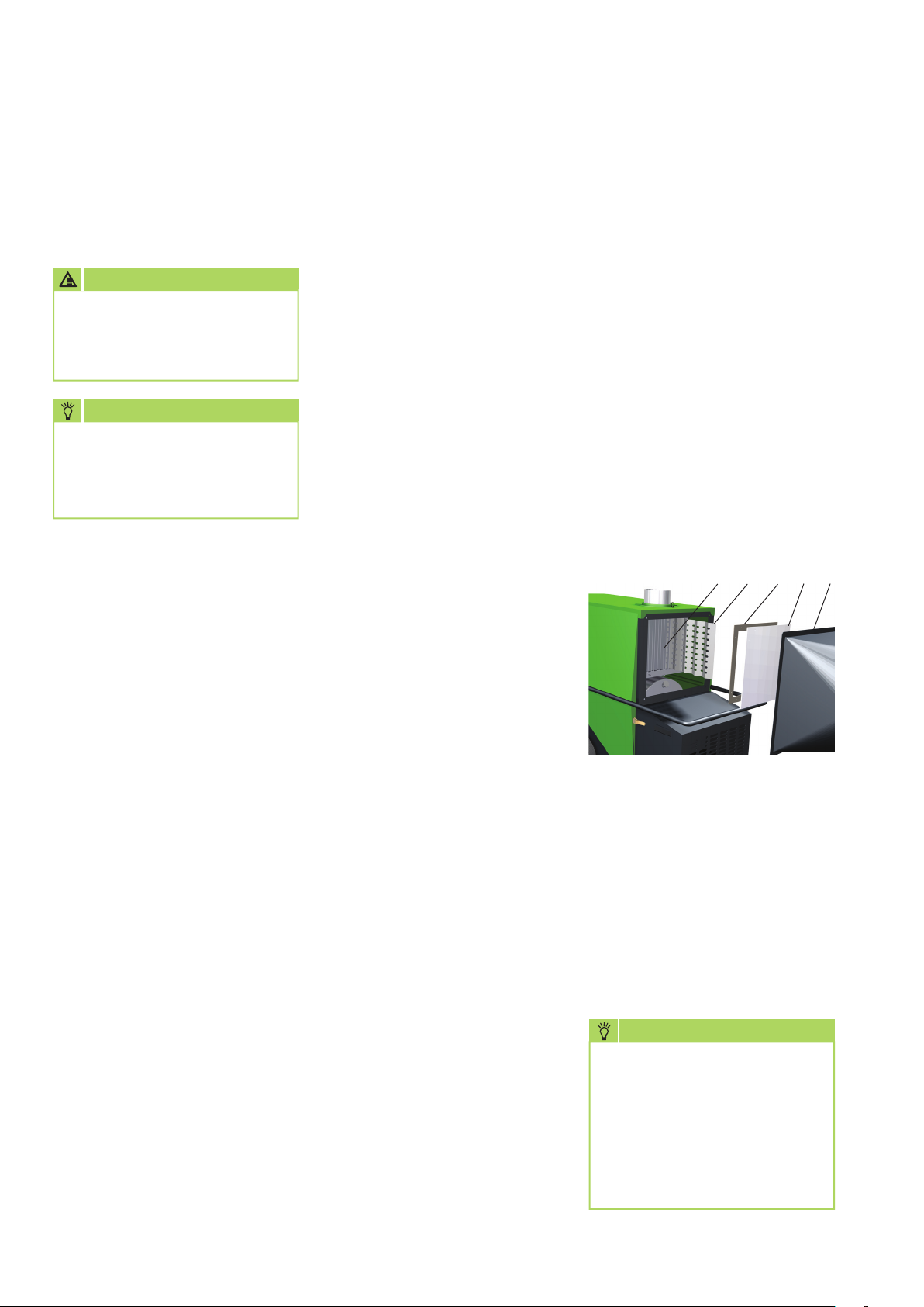
Cleaning the heat exchanger
1. Set the operating switch
to the "0" position and remove
the power plug from the mains
socket.
2. Take off the exhaust hood
[1] after removing the 4
fastening screws. Hot air hoses
present need not necessarily
be removed.
3. Remove the inspection cover
[2] and withdraw the exhaust
gas suppressors 4.
4.
Clean the flue [5].
A special cleaning brush is
available as an accessory with
EDP no. 1103110.
4 3 2 15
5. Clean the exhaust gas
suppressors or replace damaged
exhaust gas suppressors.
6. Check the seal [3]
for the inspection cover and
replace any damaged seals.
7. After the maintenance work
is complete all parts should be
carefully re-fitted in reverse
order.
NOTE
Always check that the seal
is correctly seated in
the inspection cover.
When fitting the inspection
cover ensure that the fastening
screws are tightened evenly.
12
Page 13
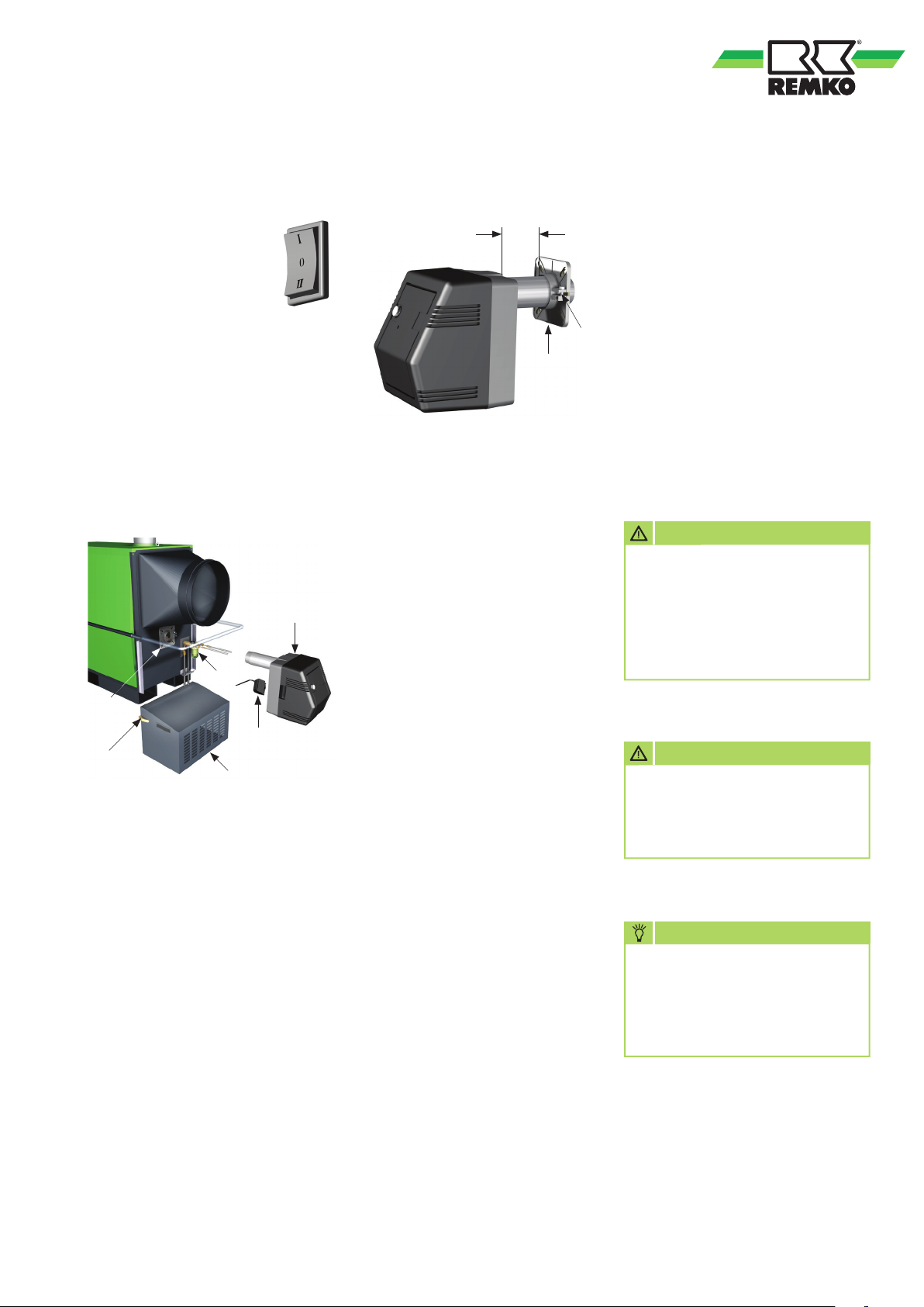
Cleaning the combustion chamber
1. Set the operating
switch to the "0"
position and remove
the power plug from
the mains socket.
2. Remove the burner cladding
[1] after opening the two quick
couplings [2].
3. Loosen the 2 lower fastening
screws on the burner flange [6].
4. Loosen the clamping screw
[7] on the burner flange 6 and
withdraw the burner towards
the front.
Installation of the burner flange
and the burner
X
6
Burner HTL 80 X = 20 mm
Burner HTL 170 X = 30 mm
1. Check the flange seal and
replace if necessary.
Additional notes for unit
maintenance
■
All work must be carried out
exclusively by authorised
specialists with the appropriate
equipment.
A log should be created and
7
kept safely by the operator
■
It is essential that the forced-air
burner is serviced and adjusted
by authorised specialists
ATTENTION
5
3
6
4
2
1
5. Withdraw the burner and
carefully set it down beside
the unit.
6. Remove the burner flange [6].
7. Take care not to damage
the flange seals, as far as is
possible.
Damaged flange seals can
result in incorrect air induction.
8. Clean the combustion chamber
through the burner opening
with a vacuum cleaner.
A special boiler cleaning set
for the REMKO industrial
vacuum cleaner is available as
an accessory.
2. Fasten the burner flange
to the unit housing with
the four fastening screws.
Note the "UP" marking!
3. Tighten the top 2 fastening
screws firmly.
4. Tighten the lower 2 fastening
screws gently and with only
light force so that the burner
flange can still be pulled
together.
5. Slide the flame tube
of the burner into the burner
flange.
Observe dimensions in
the sketch!
6. Clamp the flame tube firmly
into place with the clamping
screw [7] whilst lifting
the burner slightly (3° tilt).
7. Lastly, tighten the bottom
2 fastening screws firmly.
8. Check the fuel filter insert
[3] for leaks and replace if
necessary.
9. Re-fit burner cladding and
fasten with the quick couplings.
Repair work on the electrical
installation and on the burner
must be performed exclusively
by authorised specialists
for safety reasons.
ATTENTION
An electrical safety check must
be carried out in accordance
with VDE 0701 after any work
on the units.
NOTE
The restrictions on exhaust gas
losses per §11 of the ordinance
on small furnace systems
(1st. BImSchV) must be
observed.
s
s
s
13
Page 14
REMKO HTL 80/170
s
s
s
Troubleshooting
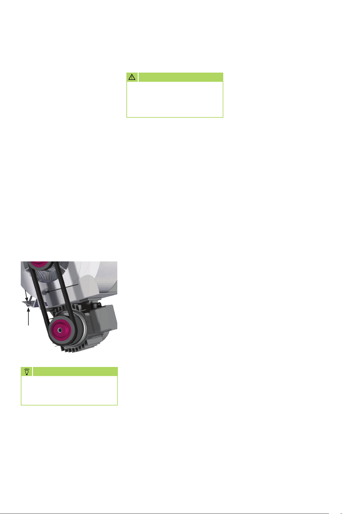
Tensioning the V-belt
1. Remove the two side air intake
grills.
2. Loosen the screws (size 13) [7].
The screw on the opposite side
is not shown.
3. Set the pre-tension
of the V-belt with the (size 17)
nuts [8] and [9].
4. The press-down deflection depth
for the V-belts should be ca.
10 mm,
5. Counter-lock the nuts [8] and
[9] again and then tighten
the two fastening screws [7]
again.
6. Re-fit the two air intake grills.
8
9
The press-down deflection
depth for the V-belts should be
ca. 10 mm (a thumb width).
"a thumb width"
NOTE
.
7
ATTENTION
Before undertaking any work
on the units, the power
plug must be removed from
the mains socket.
The unit does not start
1. Check power supply.
400 V/3~N/50Hz.
2. Move the operating switch
to the "I" (Heating) position.
3. The "Operating" indicator
light on the control panel must
illuminate.
4. Check the strapping connector
or the room thermostat plug,
if fitted, is seated properly and
making good contact.
5. Check the setting of the room
thermostat.
The temperature set must be
higher than the current room
temperature.
6. Check whether the safety
temperature limiter (STB) has
tripped.
To do so, remove the protective
cap next to the control panel.
7. Before an STB reset ensure that
the causes have been analysed
and rectified.
The following causes are
possible:
- The units were not able to cool
down because the electrical
connection was interrupted.
- Too high an outlet temperature
due to incorrectly implemented
air routing when operating with
hoses.
- Air inlets or outlets are not free
or are inadequate.
8. Check whether the "Burner
fault" indicator light
on the control panel is
illuminated. If this is the case,
then reset the automatic burner.
9. Move the operating switch
to the "II" (Ventilate) position.
If the supply air fan now starts
up the fault may well be in
the burner area.
Forced-air burner and power
supply
1. Check the oil filter(s)
for contamination. Replace
contaminated oil filter(s).
2. Check whether the shut-off
cock on the oil filter is open.
3. Check the fuel tank
for sufficient fuel level.
4. Check the heating oil
for paraffin separation.
Possible from 5 °C!
5. Check the oil hoses for damage.
6. Check the safety devices'
capillary tubes and probes
for damage or contamination.
7. Use appropriate means to check
that the temperature monitor
(TW) is functioning properly.
8. Check the forced-air
burner for possible damage
to the nozzles, baffle plate,
filter etc.
The supply air fan does not
start
1. Check the fan can move freely.
2. Check the controller fuse
in the switching cabinet.
3. Check whether the motor
protection switch in
the switching cabinet has
tripped.
4. Use appropriate means to check
that the temperature controller
(TR) is functioning properly.
14
Page 15

Intended use
The units are designed exclusively
for heating and ventilation
purposes in industrial or
commercial use (no living space
heating in private use) on the basis
of their structural design and
equipment.
The units must only be operated
by appropriately instructed
personnel.
With non-observance
of the manufacturer's
specifications, the respective
local legal requirements or after
arbitrary alterations to the units,
the manufacturer shall not be
liable for resulting damages.
Customer service and
Guarantee
As a prerequisite for any guarantee
claims to be considered, it is
essential that the ordering party
or its representative complete
and return the "certificate
of guarantee" to REMKO GmbH &
Co. KG at the time when the units
are purchased and commissioned.
The units were tested
at the factory
several times to verify their correct
function.
However, if malfunctions should
arise that cannot be remedied by
the operator with the assistance
of the troubleshooting section,
please contact your specialist
dealer or contractual partner.
Environmental
protection
and recycling
Disposing of packaging
When disposing of packaging
material, please consider our
environment.
Our units are carefully packed
and delivered in sturdy transport
packaging made from cardboard
and on a wooden pallet.
The packaging materials are
environmentally-friendly and can
be recycled.
By recycling packaging materials,
you make a valuable contribution
to the reduction of waste and
conservation of raw materials.
Therefore, only dispose
of packaging material
at appropriate collection points.
NOTE
Operation other than the types
listed in this operating manual
is prohibited.
With non-observance, any
liability and claim to guarantee
expire.
!
ATTENTION
Copyright
The redistribution, even in part,
or the use of this documentation
for purposes other than intended
is strictly prohibited without
the written authorisation of
REMKO GmbH & Co. KG
NOTE
Adjustment and maintenance
work may only be carried
out by authorised qualified
technicians.
Disposal of the old unit
The manufacturing process
for the units is subject
to continuous quality control.
Only high-grade materials are
processed, the majority of which
are recyclable.
You also contribute
to environmental protection
by ensuring that your old
equipment is only disposed of in
an environmentally-friendly
manner.
Therefore, only bring the old
unit to an authorised recycling
business or to an appropriate
collection point.
15
Page 16
REMKO HTL 80/170
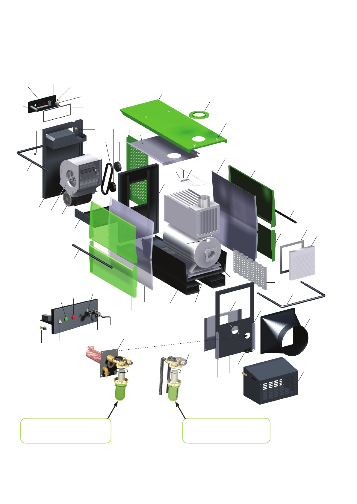
Exploded view of the unit
41
47
48
40
55
60
54
61
8
62
42
60
50
52
53
51
36
1
44
43
2
3
60
35
61
62
Temperature probe
34
4
46
5
33
32
46
68
67
61
REMKO Multiflex oil pre-heating,
serial with HTL 170 with factoryfitted oil burner.
66
70
71
69
72
20
38
3
21
22
23
27
6
30
7
24
12
REMKO 2-strand oil filter,
Serial with HTL 80 with factoryfitted oil burner.
11
13
10
31
45
12
25
26
16
We reserve the right to modify the dimensions and design as part of the ongoing technical development process.
Page 17
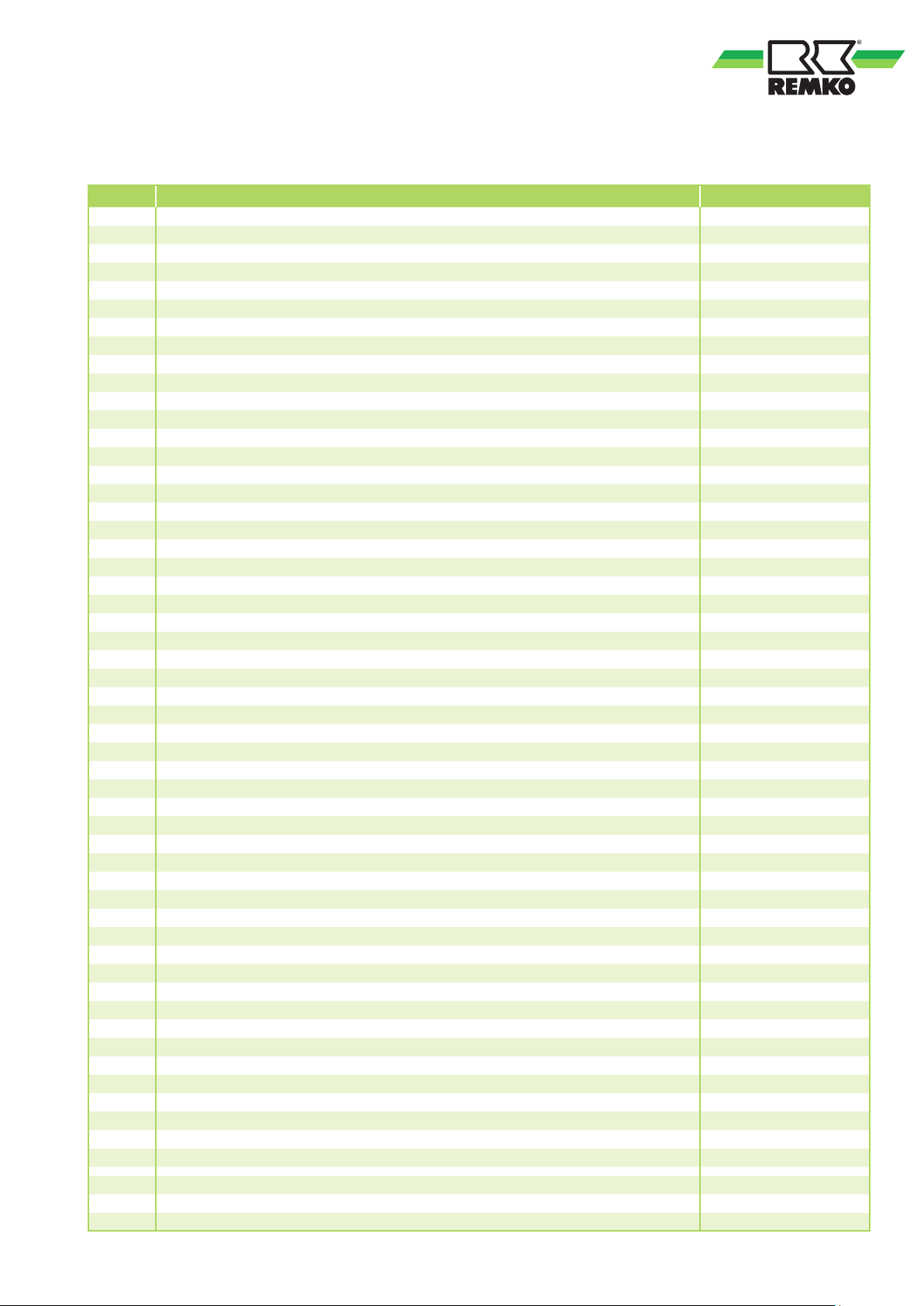
Spare parts list
No. Description HTL 80 HTL 170
01 Cover panel 1104740-1 1104851
02 Upper insulation 1104741-1 1104852
03 Insulation right / left 1104742 1104853
04 Upper side cover (right / left) 1104743 1104854
05 Lower side cover (right / left) 1104744-1 1104855
06 Lower insulation 1104746 1104872
07 Base tray, front 1104745 1104856
08 Base tray, rear 1104836 1104857
10 Front wall cmpl. 1104755 1104858
11 Front wall insulation 1104756 1104786
12 Guide bracket 1104757 1104787
13 Hose pass-through 1104722 1104722
20 Multiflex oil pre-heating, compl. 1071411 1071411
21 O-ring 1108464 1108464
22 Filter insert 1108462 1108462
23 Oil filter cup 1108463 1108463
24 Oil filter, compl. 1002526 —
25 Outlet nozzle 1104758 1104788
26 Burner cladding cmpl. 1104759 1104789
27 Transport skids (set) 1002528-1 1002529-1
30 Combustion chamber, cmpl. 1104761-2 1104806-2
31 Exhaust gas suppressor (set) 1104793 1104810
32 Inspection cover 1104763 1104794
33 Seal for inspection cover 1104764 1104795
34 Sealing cap 1104728 1104784
35 Centre wall 1104841 1104862
36 Intake grill, right / left 1104842 1104863
40 Back wall 1104843 1104864
41 Switching cabinet cmpl. 1104783-1 1104865
42 Seal for switching cabinet 1104754 1104866
43 Crane eye 1102554 1102554
44 Exhaust gas nozzle collar 1104732 1104796
45 Transportation bracket, front 1104765 1104867
46 Transportation bracket, middle 1104767 1104868
47 Transportation bracket, rear 1104766-1 1104869
48 Spacing roller 1104849 1104849
50 Radial fan 1108603 1108607
51 Fan belt pulley 1113111 1102777
52 V-belt 1113112 1102774
53 Motor belt pulley 1113110 1102784
54 Electric motor IE2 1102737 1102733
55 Motor bracket with clamp 1104850 1104870
60 Temperature controller (TR) 1103166 1103166
61 Safety temperature limiter (STB) 1101197 1101197
62 Temperature monitor (TW) 1103146 1103146
66 Operating switch 1101188 1101188
67 Indicator light, green (Operation) 1105514 1105514
68 Indicator light, red (Burner fault) 1105363 1105363
69 Reset button (Burner) 1103408 1103408
70 Thermostat receptacle 1101018 1101018
71 Strapping plug 1101019 1101019
72 Mains cable with plug 1104701 1105100
Not shown
Not shown
Not shown
Burner connector, 7-pole 1102537 1102537
Drum fitting, cmpl. 1002544 1002544
Cleaning brush, cmpl. 1103110 1103110
When ordering spare parts, please state the EDP no., unit number and type (see name plate)!
17
Page 18
REMKO HTL 80/170
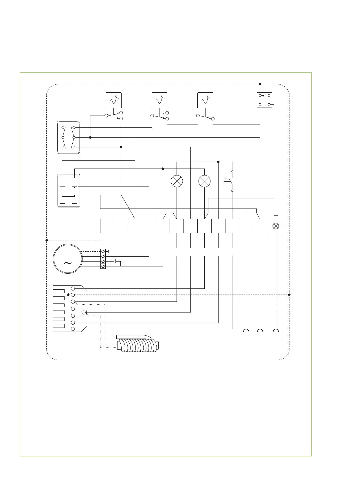
Electrical wiring diagram HTL 80
TR
TW
STB
RT
1
3
2
1A
2A
3A
31
34
B
S1
I
II
HR
M
2
1
4
4B
5B
6B
A
11
14
1232
KL
10
1112
schwarz
C
blau
4
1
2 2
H2 H1
N
N
#2
1
S2
5
6789
#1
#5
3
4
#4
#3
12
L1
N
T1
T2
S3
B4
WS
HW 07.13
Legend:
C = Capacitor
H1 = Operating lamp (green)
H2 = External burner fault lamp (red)
HR = Auxiliary relay
KL = Terminal block
M = B3 Fan motor
ÖV = Multiflex oil pre-heating (option)
ÖV
Option (EDV-Nr.: 1071411)
N
230 V / 50 Hz
RT = Thermostat receptacle
S1 = Operating switch
S2 = Reset button - burner relay
STB = Safety temperature limiter
TR = Temperature controller
TW = Temperature monitoring device
WS = Burner connector, 7-pole
(only fitted with factory burner delivery)
L1
PE
18
We reserve the right to modify the dimensions and design as part of the ongoing technical development process.
Page 19
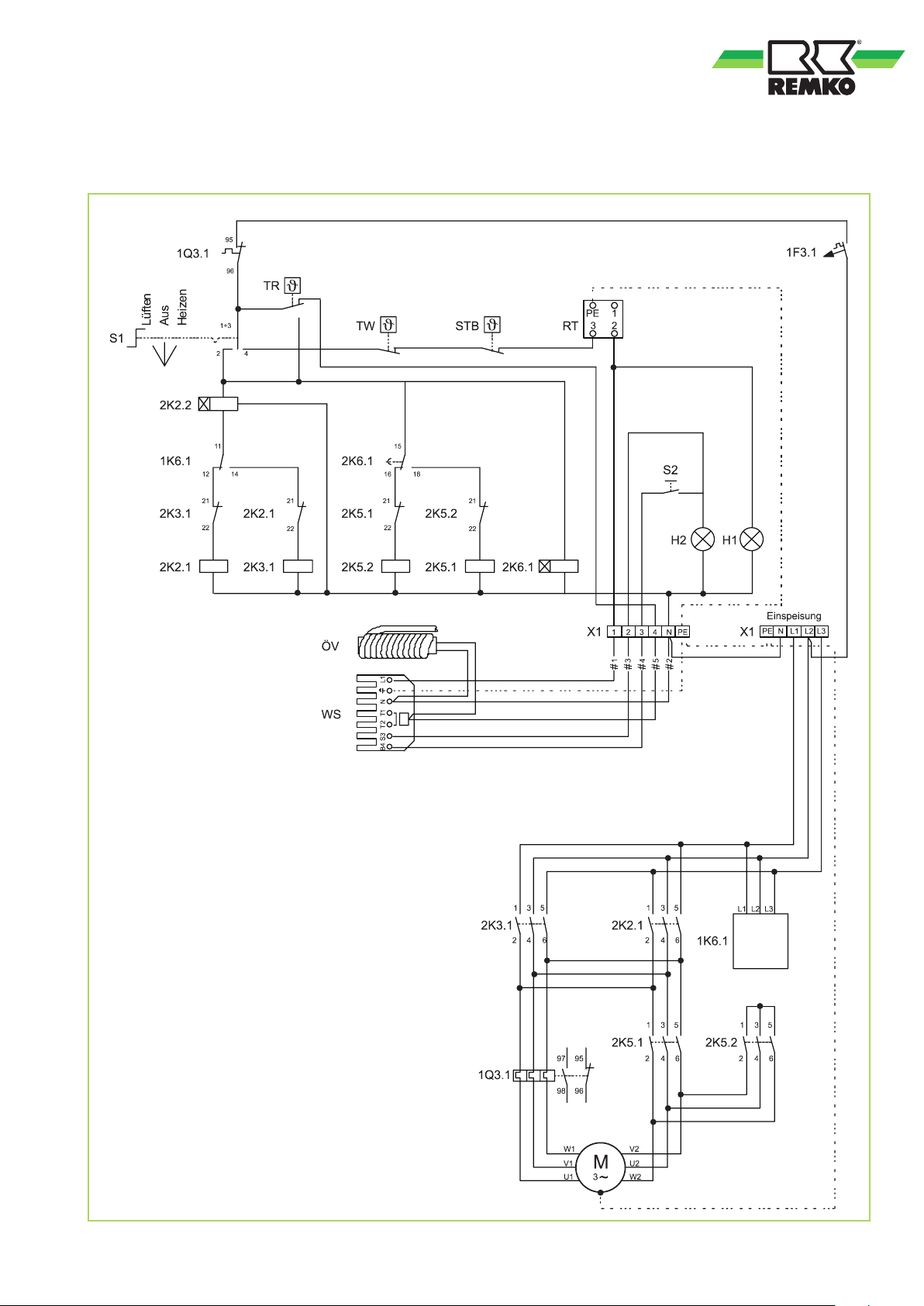
Electrical wiring diagram HTL 170
Control circuit
Legend:
S1 = Operating switch
S2 = Reset button (burner)
H1 = Operating lamp (green)
H2 = External burner fault lamp (red)
TR = Temperature controller
TW = Temperature monitoring device
STB = Safety temperature limiter
X1 = Terminal block
M = Fan motor
WS = Burner connector, 7-pole
RT = Thermostat receptacle
ÖV = Multiflex oil pre-heating
1F3.1 = Controller fuse
2K2.1 = Mains fuse
2K2.2 = Time relay
2K3.1 = Mains fuse
2K5.1 = Delta contactor
2K5.2 = Star contactor
1K6.1 = Phase sequence relay
2K6.1 = Star-delta relay
1Q3.1 = Motor overload protection switch
Load circuit
We reserve the right to modify the dimensions and design as part of the ongoing technical development process.
19
Page 20
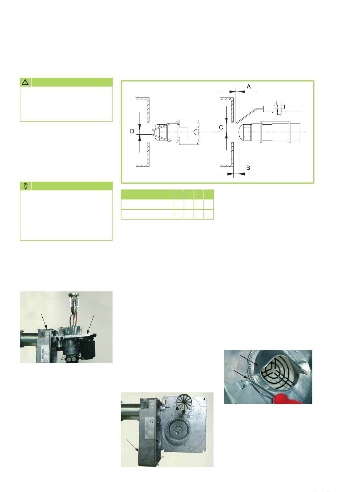
REMKO HTL 80/170
Commissioning the forced-air oil burner
Preparatory tasks
ATTENTION
The commissioning
of the forced-air oil burner
may only be carried out by
trained specialists.
After loosening the 4 fastening
bolts the mounting baseplate M is
pulled off the housing G.
From size SL 44, 6 fastening screws
must be removed (note marking
arrows).
NOTE
Because the air flap, up to size
44, is sprung this should
be closed beforehand with
the help of the adjustment
screw [3] (turn adjusting screw
approx. as far as scale value 1).
The most important functional
parts for the installation /
maintenance are now immediately
accessible, as per the respective
requirements.
Fig.: 1
MG
Adjusting the ignition electrode and baffle plate
Size / dimensions A B C D
HTL 80 5 5 7 3
HTL 170 7 8 5 3
Required nozzle size
The selection of the required oil
nozzle is dependent on the pump
pressure and the unit capacity.
Only a nozzle that is approved
for the respective combustion
chamber geometry with
corresponding spray angle and
cone characteristics may be used.
Refer to the technical data
for the required oil nozzle size.
All sizes are approximate values
and are in mm. The optimum
setting must be adapted
to the unit-specific and structural
conditions.
Air inlet nozzle
The required blower pressure can
be adjusted with the adjustable air
inlet nozzle A in accordance with
the combustion chamber resistance
and chimney draft, without having
to change the output diameter.
1. Loosen the Allen screw B.
2. Turn the air inlet nozzle
A to the desired position
(note arrows!).
"min" = Smaller blower pressure
"max" = Larger blower pressure
For maintenance work or
for installing / replacing the oil
nozzle, the mounting baseplate M
can be positioned on the burner
housing G in 2 ways (see figs. 1
and 2).
The baseplate can be positioned
in the desired / possible position
on the special mounting points in
accordance with the unit-specific
options.
20
Fig.: 2
G
A
B
Mounting baseplate
M
After having replaced the nozzle
and carried out any adjustments
required to the air inlet nozzle A,
the mounting baseplate M is refitted in reverse order.
Page 21
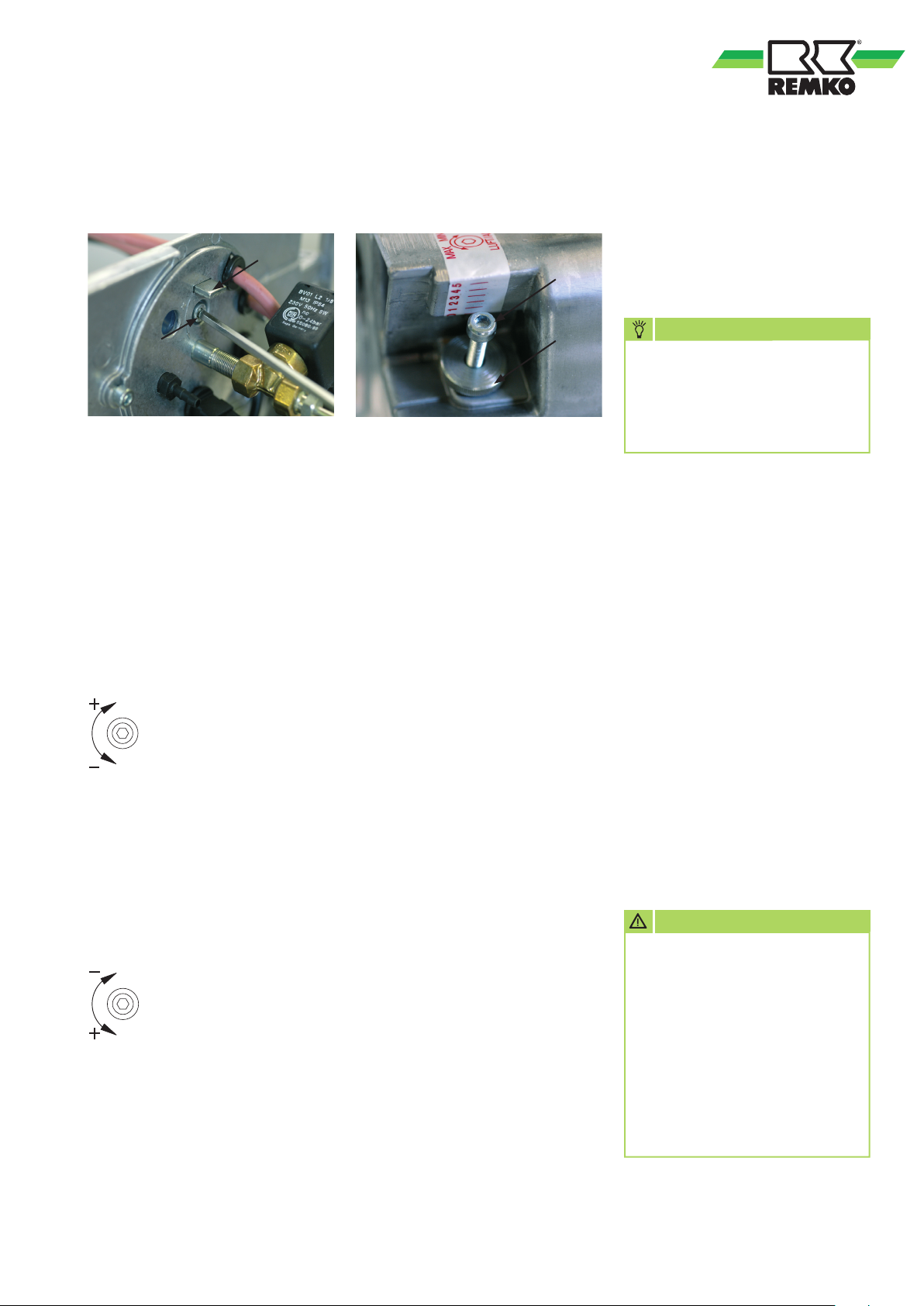
Adjusting the secondary air
(Nozzle fitting adjustment)
2
Air flap
Setting the pump pressure
The pump pressure should be
adjusted, and checked if necessary,
3
during burner commissioning and
during every service.
1
Carry out the presetting
of the secondary air as follows:
Set the nozzle fitting 2
to the desired value with
the adjusting screw 1.
HTL80
Turning to the left (–)
= smaller scale value
larger pressure behind
the baffle plate
lower power range
Turning to the right (+)
= larger scale value
smaller pressure behind
the baffle plate
upper power range
HTL 170
Turning to the left (+)
= larger scale value
smaller pressure behind
the baffle plate
upper power range
Turning to the right (–)
= smaller scale value
larger pressure behind
the baffle plate
lower power range
4
The quantity of combustion air
required is adjusted by means
of the adjusting screw 3.
The air flap is set according
to the unit capacity and the further
burner settings.
Adjusting the air flap
Adjust the air flap as follows:
1. Loosen the knurled nut 4.
2. Set the adjusting screw 3
accordingly.
Turn to the right = Less air
Turn to the left = More air
4. After having set the adjusting
screw 3 lock it again with
the knurled knob 4.
Additional notes
■
If the flame should give off
sooty smoke or break away
with a fully opened air flap,
reduce the pressure behind
the baffle plate with the help
of the secondary air setting
■
It may also be necessary
to open the air inlet nozzle
further
NOTE
Never let the pump run
for extended periods without
any fuel. Never leave the units
for extended periods with
a pump that has run dry.
Adjust the pump pressure as follows:
1. Remove the stopper
on the measurement nozzle
"P".
2. Fit a suitable oil pressure
manometer here.
3. Open all oil shut-off devices.
4. Switch on the burner.
5. Set the required oil pressure in
accordance with the nozzle size
and the unit capacity.
6. Switch off the burner after
completing the adjustments.
7. Remove the oil pressure
manometer again.
Re-fit stopper incl. seal.
ATTENTION
If the burner should carry out
a fault shut-down once again
after the start phase, then
another reset should be carried
out after a waiting period
of 5 minutes has passed.
Further reset procedures must
be prohibited as there is
a danger of deflagration.
All values provided are only preliminary settings and must be adapted or calibrated in accordance with the exhaust gas analysis.
21
Page 22

REMKO HTL 80/170
Maintenance protocol
Unit type: .................................. Unit number: ...................................
1 2 3 4 5 6 7 8 9 10 11 12 13 14 15 16 17 18 19 20
Unit cleaned - outside Unit cleaned - inside Fan blade cleaned
Combustion chamber cleaned
Heat exchanger cleaned
Exhaust gas suppressors replaced
Inspection cover seal replaced
Fuel filter insert replaced
Safety equipment checked
Safety devices checked
Unit checked for damage
Electrical safety check
Burner maintenance *)
Test run
Comments: ..........................................................................................................................................................
.............................................................................................................................................................................
.............................................................................................................................................................................
1. Date: ..............
..............................
Signature
6. Date: ..............
..............................
Signature
11. Date: ............
..............................
Signature
16. Date: ............
..............................
Signature
2. Date: ..............
..............................
Signature
7. Date: ..............
..............................
Signature
12. Date: ............
..............................
Signature
17. Date: ............
..............................
Signature
3. Date: ..............
..............................
Signature
8. Date: ..............
..............................
Signature
13. Date: ............
..............................
Signature
18. Date: ............
..............................
Signature
4. Date: ..............
..............................
Signature
9. Date: ..............
..............................
Signature
14. Date: ............
..............................
Signature
19. Date: ............
..............................
Signature
5. Date: ..............
..............................
Signature
10. Date: ............
..............................
Signature
15. Date: ............
..............................
Signature
20. Date: ............
..............................
Signature
*) Have the forced-air burner maintained and adjusted only by authorised specialists and in accordance with the legal
provisions (1st. BImSchV.). A corresponding measurement log should be generated.
Unit to be maintained only by authorised specialists in accordance with the statutory regulations.
22
Page 23
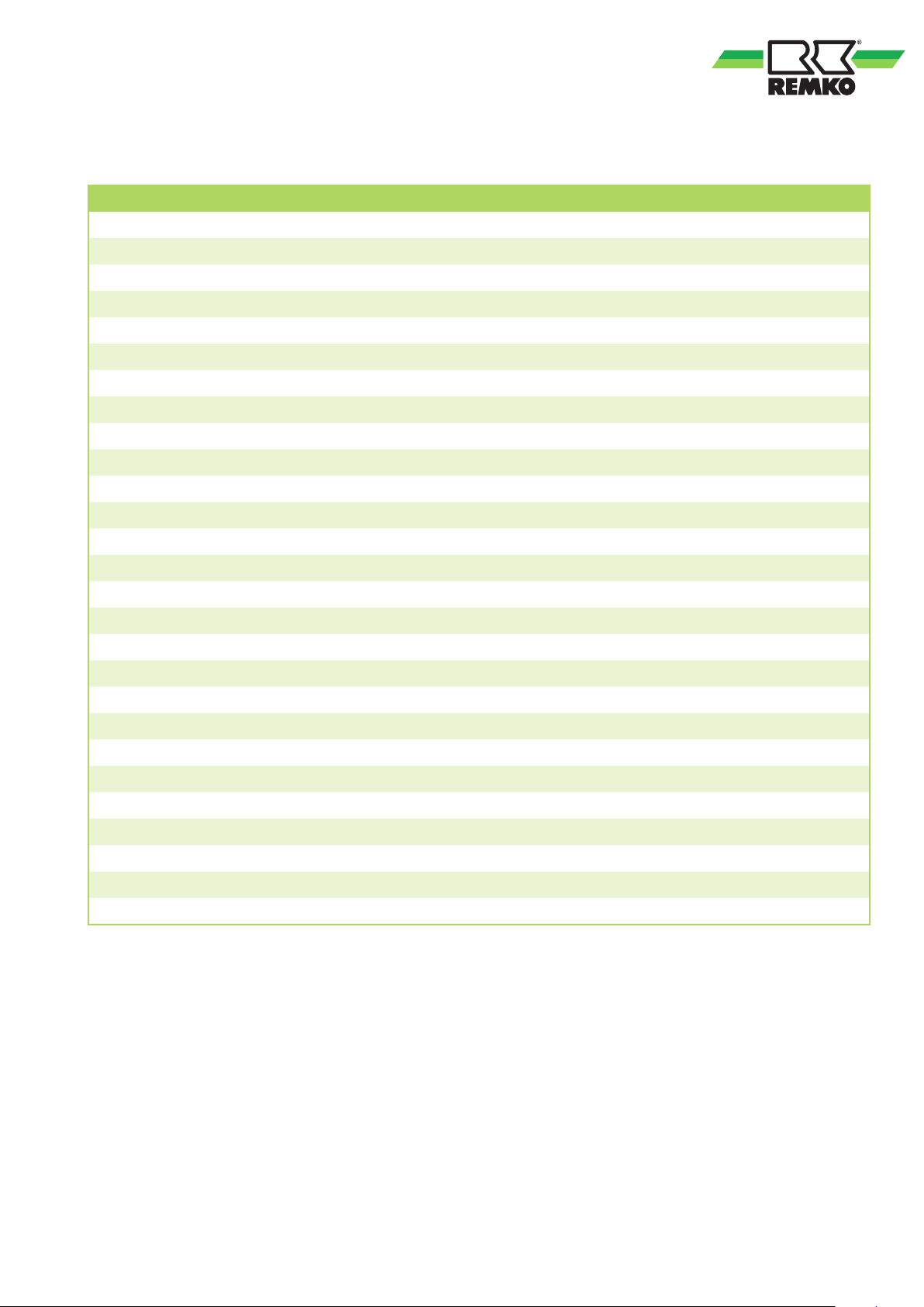
Technical data
Unit type
Max. nominal heating capacity kW 84 155
HTL 80 HTL 170
Nominal heat capacity kW 77 143
1)
Nominal flow rate
(Max. total) pressure Pa 410 520
m3/h 6,140 10,340
Fuel Heating oil EL acc. to DIN 51603-1 or diesel fuel
Max. fuel consumption l/h 8.3 15.5
2)
Danfoss oil nozzle
Pump pressure,
Max. exhaust gas loss % 9 9
Exhaust gas flow,
Combustion chamber resistance,
USG 1.75 / 60°S 3.00 / 80°S
approx.
2)
bar 12 13
approx. kg/h 136 240
approx. Pa 100 110
Required chimney draft Pa 0 0
Power supply V/Hz 230/1~/50 400/3~N / 50
Max. power consumption (complete unit) kW 1.75 3.4
Max. nominal current (complete unit) A 9.5 8.0
Max. power consumption
Customer-provided electrical protection A 16 16
(Multiflex oil preheating) W -- 30
Temperature increase (∆
Sound pressure level L
) K 48 54
t
3)
pA
1m
dB (A) 62 65
Air outlet ø mm 400 500
Air intake Ø
4)
mm 2 x 400 2 x 500
Exhaust gas nozzles ø mm 150 200
Dimensions: Length mm 2.000 2.380
Width mm 655 785
Height mm 1.060 1.250
Weight with forced-air oil burner kg 248 385
EDP no.: (with/without oil burner) 132780/132770 132300/132290
1) At
∆
45K / 1.2 kg/m3)
t
2) The specified nozzle sizes and pump pressures are based on test bench results.
The oil flow rate was derived from this.
Based on the product-specific nozzle and pressure tolerances as well as the oil temperature, the specifications should only
be considered guidelines.
3) Noise level measurement (with hose and without burner operation) DIN 45635 - 01 - KL 3
4) Only with intake ports (accessories) for recirculating or mixed air operation
We reserve the right to modify the dimensions and design as part of the ongoing technical development process.
23
Page 24
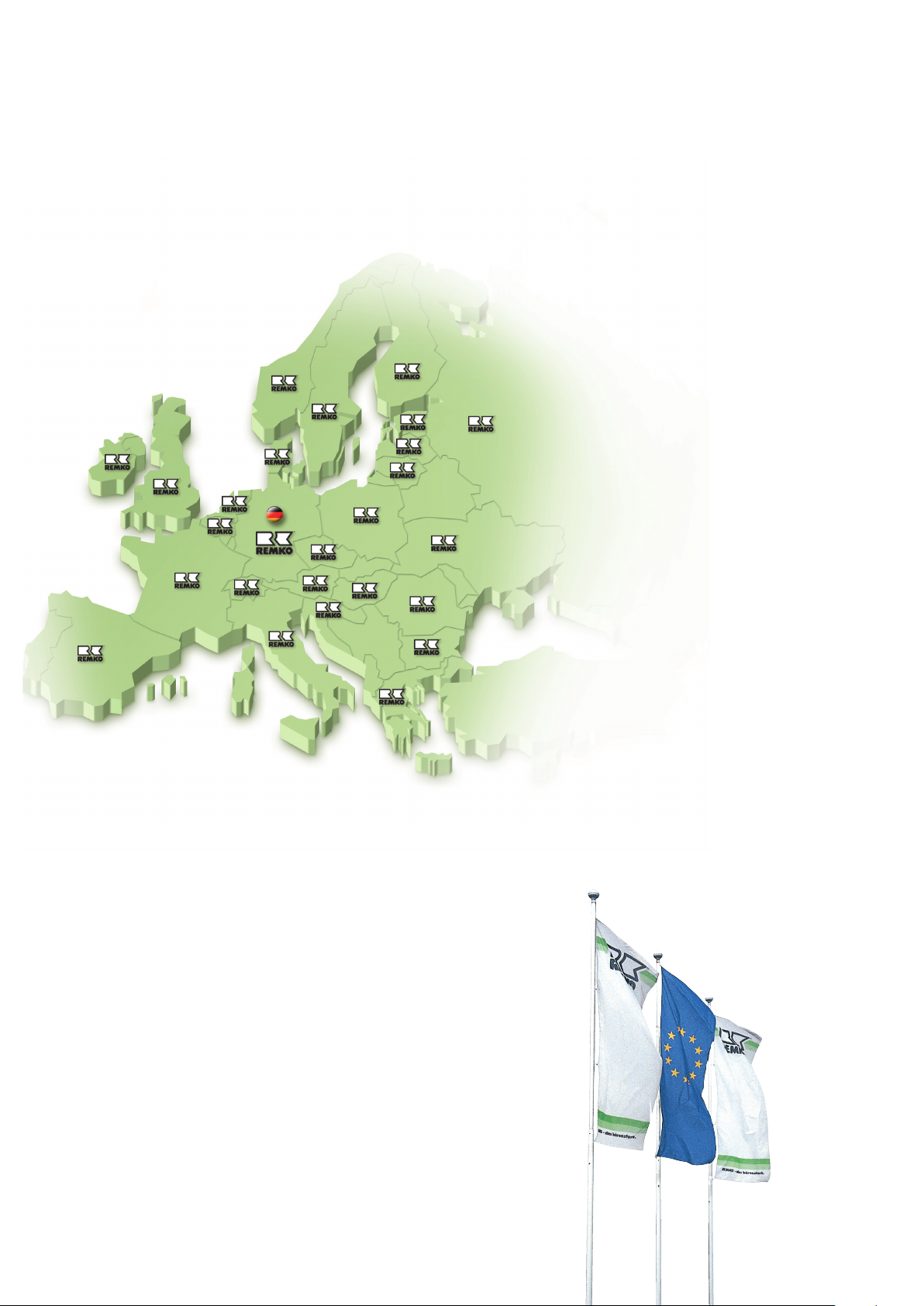
REMKO INTERNATIONAL
... and also right in your neighbourhood!
Take advantage of our experience and advice
Consulting
Thanks to intensive training,
our consultants are always
completely up-to-date when
it comes to technical expertise.
This has given us the reputation
of being more than just
an excellent, reliable supplier:
REMKO, a partner who
helps to solve problems.
Sales
REMKO offers not just a wellestablished sales network both
nationally and internationally,
but also has exceptionally highlyqualified sales specialists.
REMKO employees in the
field are more than mere
salespeople: above all, they must
be advisers to our customers
in air conditioning and heating
technology.
Customer service
Our units operate precisely and
reliably. However, in the event
of a malfunction REMKO customer
service is quickly on the scene.
Our comprehensive network
of experienced dealers guarantees
quick and reliable service.
REMKO GmbH & Co. KG
Klima- und Wärmetechnik
Im Seelenkamp 12 D-32791 Lage
Postfach 1827 D-32777 Lage
Telephone +49 5232 606-0
Fax +49 5232 606-260
e-mail [email protected]
Internet www.remko.de
We reserve the right to make technical changes and provide no warranty as to the accuracy of this data!
 Loading...