

Page 1

REMKO GTF-5
Day/ Night Temperature Control
for REMKO GPA-C
Edition GB - P06
Operation
Technology
Original
REMKO
REMKO - powerful like a bear
Page 2
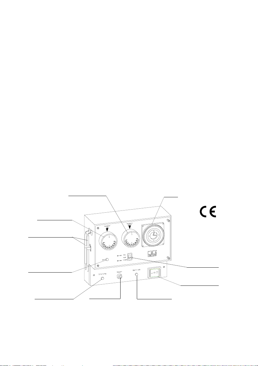
Description of Device
The REMKO GTF-5 temperature control is a combination of a remote
control and an automatic day/night temperature control for the heaters in
the GPA-C series.
A temperature control can only be used to control a single heater.
G
A temperature control is used for the unit functions heating, ventilating
and resetting of the heater.
Power connection, unit operation and burner malfunction are displayed
by the control lights.
Day and night temperatures can be set separately via the respective
thermostats. The integrated weekly clock timer (TIMER with power reserve) lets heating operation be pre-programmed for the week.
The temperature control is ready for plug in and is supplied with a 6 m
long control cable incl. 7-pole plug. This is connected at the back of the
heater to the appropriate slot.
Day thermostat
Temperature sensor
Power control light
The temperature control may only be connected using the
7-pole plug of the GPA-C heater intended for this purpose.
G
2
Night thermostat
Reset button Operating light Malfunction light
Timer
Mode selector
Operating switch
Page 3

Functionality
The desired room temperature is set with either the day or night thermostats.
The thermostats can be set using the 3-stage mode selector.
Mode DAY The room temperature is only controlled via the day
thermostat.
OFF No control function, the temperature function is switched
off, the heating function is also off for the warm air heater.
Mode TIMER The room temperature is controlled by the pre pro grammed times and the set day/night temperatures.
Installation
Position the housing with the temperature sensors so that it is visible
from the heater to guarantee optimum sensor function.
If the temperature control is mounted on cold, outdoor walls, the customer must install an insulation panel between the wall and the thermostat.
It should not be installed in niches, corners or similar locations.
The thermostat sensors may not be directly exposed to a particu-
G
larly cold or hot stream of air.
Initial Operation
l Set up and install the heater in accordance with the instructions in the
operating manual.
l Plug the temperature control into the correct slot at the back of the
heater.
l Activate the current supply for the heater via the main/emergency
switch. The green power supply light should now be illuminated on the
control unit.
l The control unit is ready for operation once the timer, the mode se
lector and the desired room temperature have been set.
l Put the heater into operation in accordance with the operating instruc tions.
Note: The green control light (operation) is only illuminated during
heating operation.
3
Page 4
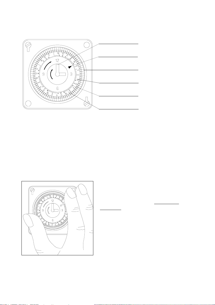
Timer display
Minutes
Selection arrow
Switch segment
Clock
Day of the week
Rotating selector
Setting the day and time
This procedure is required:
1. For initial operation
2. When setting and resetting the clock for daylight savings time
3. After a long period with no power supply
G
4
Rotate the switch in the direction of
the arrow until the current day is
next to the selection arrow.
E.g. Fr = Friday.
The timer has a power reserve (approx. 120 h). If the power supply
to the temperature control is interrupted for a longer period of
time, the timer must be reprogrammed.
Page 5
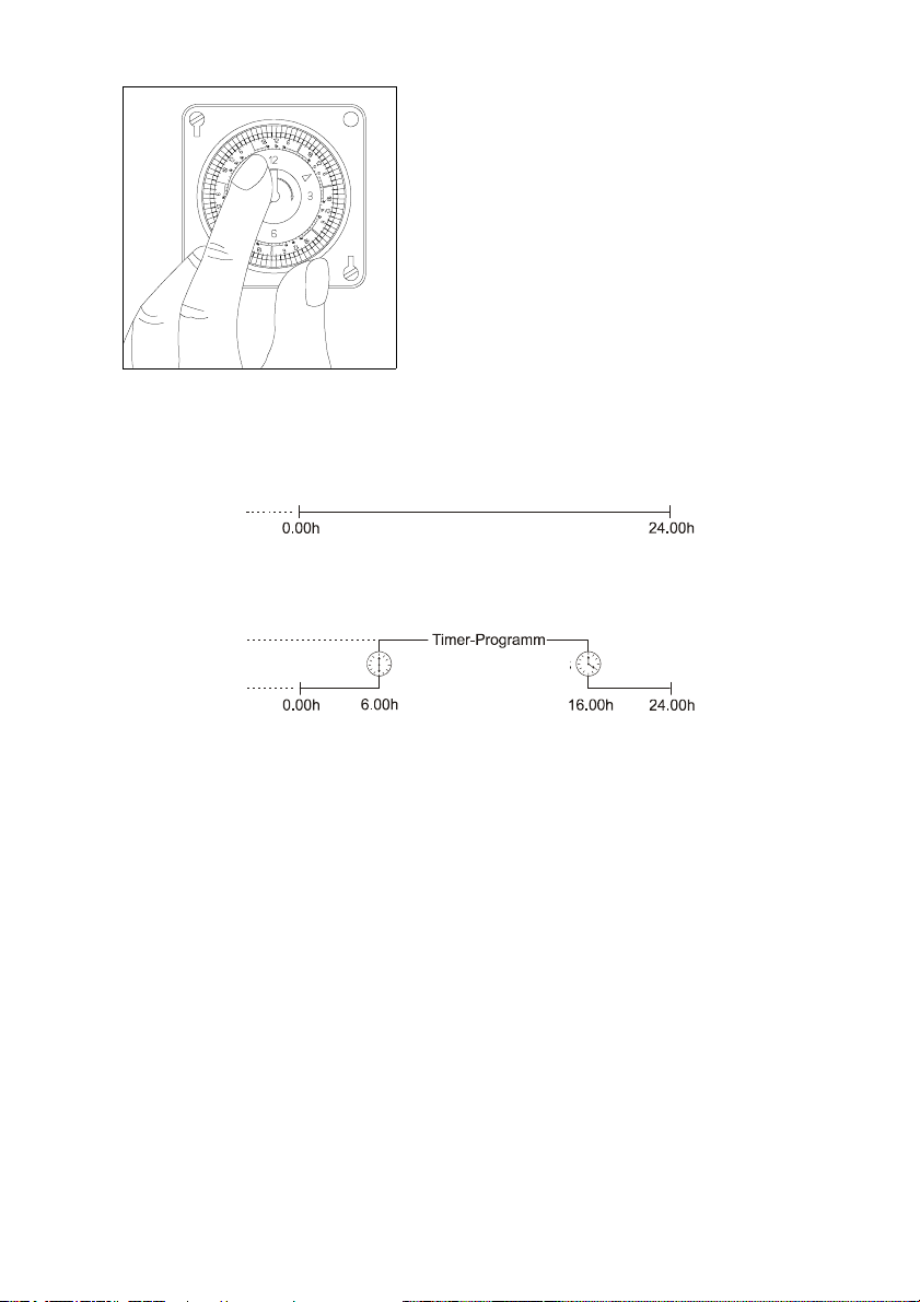
Turn the minutes pointer in the direction of the arrow until the current
time appears next to the selection
arrow.
E.g. Fr 9:00 o‘clock.
Setting and programming example:
DAY mode
Room temp. 20 °C
(Day thermostat)
TIMER mode
Room temp. 20 °C
(Day thermostat)
Room temp. 10 °C
(Night thermostat)
ON OFF
Setting the Timer
The timer function can only be set if the switch segment has been
pressed out!
Segment pressed out ð Day temperature
Segment pressed in
The activation times are set via the green switch segments.
7 x 12 = 84 segment .
1 switch segment = 2 hours
The corresponding switch segments are pressed out using for example,
a screwdriver.
Each day of the week is set individually.
ð Night temperature
5
Page 6
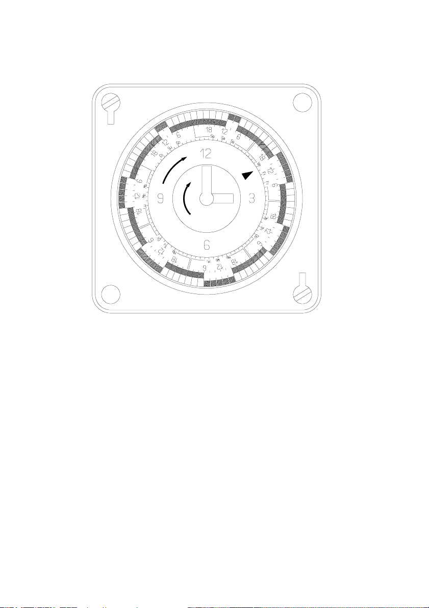
Sample timer setting:
Current day: Friday (Fr)
Current time: 15:00 o‘clock
Selection switch position: Timer mode
Timer activation functions:
Mo - Fr:
Switched off: 00:00 to 06:00 o‘clock
Switched on: 06:00 to 16:00 o‘clock
Switched off: 16:00 to 24:00 o‘clock
Sa - So:
Switched off: 00:00 to 08:00 o‘clock
Switched on: 08:00 to 12:00 o‘clock
Switched off: 12:00 to 24:00 o‘clock
The day thermostat is active during the times when the unit is switched
on. When switched off, the night thermostat is active.
6
Page 7
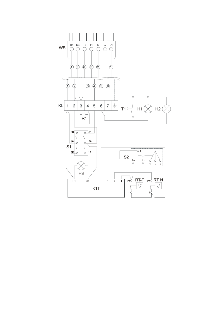
Wiring Diagram
Plug for heater
H1 = Control light green
H2 = Control light red
H3 = Power control light green
KL = Terminal strip
R1 = Resistance
RT-N = Night thermostat
Only have the REMKO GTF 5 temperature control installed and
put into operation by authorised personnel in accordance with the
G
relevant regulations.
Operation/handling which does not comply with these instructions is
prohibited! In cases of non-compliance, we assume no liability and the
guarantee becomes null and void.
RT-T = Day thermostat
S1 = Operating switch
S2 = Mode selector
T1 = Reset button
WS = Plug, 7-pole
7
Page 8

REMKO GmbH & Co. KG
Klima- und Wärmetechnik
D-32791 Lage • Im Seelenkamp 12
D-32777 Lage • PO Box 1827
Phone +49 (5232) 606 - 0
Fax +49 (5232) 606260
E-Mail: [email protected]
Internet: www.remko.de
 Loading...