

Page 1
REMKO
TANK SYSTEMS
ETS 300
Hot water tank
Operation · Technology
Edition GB-C05
Page 2

Page 3
Contents
Safety notes
Environmental protection and recycling
Warranty
Intended use
Description
Operation
Decommissioning
Care and maintenance
Installation instructions for qualified personnel
Installation
Electrical connection
Before commissioning
Commissioning
4
5
5
5
5-6
6
6
6-7
8-9
10-13
14
14
15
Made by REMKO
Unit dimensions
Technical data
Carefully read this original operating manual
prior to commissioning / using the equipment!
These original instructions are an integral part of the unit
and must always be kept in the vicinity of the installation
location or on the unit itself.
This operating manual is a translation of the German original.
Subject to modifications; no liability accepted for errors
or misprints!
16
17
3
Page 4

REMKO ETS 300
Safety notes
Carefully read the operating manual
before placing the unit in service for
the first time. It provides useful tips
notes and hazard warnings to prevent
injury and material damage. Failure
to follow the directions in this manual
can endanger persons, the environment
and the equipment itself and will void any
claims for liability.
■ Keep this manual in the vicinity
of the units.
■ Only qualified personnel may
set up and install the units
and components.
■ The set-up, connection, and operation
of the unit and its components must
be in accordance with the operating
conditions stipulated in this manual
and comply with all applicable local
regulations
■ Modification of the units
and components supplied by REMKO
is not permitted and can cause
malfunctions.
■ Units and components may not
be operated in areas where there
is an increased risk of damage.
Observe the minimum clearances.
■ The electrical supply is to be adapted
to the requirements of the units.
■ The operational safety of units
and components is only assured
if they are fully assembled and used
as intended. Safety devices may not
be modified or bypassed.
■ Do not operate units or components
if there are obvious defects or signs
of damage.
■ The units and components must
be kept at an adequate distance
from flammable, explosive,
combustible, abrasive and dirty areas
or atmospheres.
■ Installation, repair and maintenance
work may only be carried out
by authorised specialists. Visual
inspections and cleaning can
be performed by the operator as long
as the equipment is disconnected
from the power.
■ Take appropriate precautions when
performing installation, repair
or maintenance work or cleaning
the unit to make sure the unit does
not pose a danger to persons.
4
Page 5
Environmental
protection and recycling
Disposing of packaging
All products are packed for transport
in environmentally friendly materials.
Make a valuable contribution to reducing
waste and sustaining raw materials.
Only dispose of packaging at approved
collection points.
Disposing of the components
The manufacturing process for the units
is subject to continuous quality
control. Only high-grade materials
are processed, the majority of which are
recyclable. Help protect the environment
by only disposing of the components
in accordance with local regulations
and in an environmentally safe manner,
e.g. through authorised disposal and
recycling specialists or at collection points.
Warranty
The warranty conditions are listed
in the "General terms and conditions".
Please contact your direct contractual
partner about this first instance.
Intended use
The tanks are used for the storage of hot
water.
Any different or additional use is a nonintended use. The manufacturer/supplier
assumes no liability for damages arising
from a non-intended use. The user bears
the sole risk in such cases.
Intended use also includes working
in accordance with the operating and
installation instructions and complying
with the maintenance requirements.
Description
The tanks are used for the storage of hot
water.
The tank volume can be adapted to your
particular needs by connecting several
tanks to form batteries.
The tank is enamelled and has a doublewound, smooth-pipe heat exchanger
with an especially large heat exchanger
surface area of 2.6 m2.
In the inside tank a magnesium false
anode is installed in accordance with
DIN 4753.
The insulation of the hot water storage
tank ETS 300 is comprised of a 50 mm
thick PUR insulation (CFC, HCFC
and HFC free).
The tank is encased in a foil casing
(delivered separately for transport
protection).
A blank flange cover D180 is installed
for the retrofitting of a finned tube heat
exchanger or flange heating cartridge
(legionella protection).
5
Page 6
REMKO ETS 300
The tank has connections for circulation
(3/4" IG) as well as a cold water supply
and hot water outlet (1" IG).
Operation
Manual operation is not necessary.
Decommissioning
Temporary shutdown
1. If necessary, disconnect the electrical
connection of the flange heating
cartridge at all poles.
2. Drain the tank in areas where
it is at risk from frost and before
the onset of winter.
3. After closing the shut-off valve
in the cold water supply, the water
is drained through the drain valve
of the safety combination while
all the hot water valves of the service
water fixtures are open. Partial
emptying is also possible through
the safety valve in the expansion
water funnel (drip catcher). For this
purpose the safety valve is turned
to the "Test" position.
! ATTENTION
When placing the tank back into
service, ensure that it is filled with
water and that water which is free
of bubbles is escaping from the
valves!
Permanent decommissioning
Ensure that equipment and components
are disposed of in accordance with local
regulations, e.g. through authorised
disposal and recycling specialists
or at collection points.
REMKO GmbH & Co. KG or your
contractual partner will be pleased
to provide a list of certified firms in your
area.
Care and maintenance
Care
■
Clean the units with a damp cloth.
(adding, for instance, a liquid
household cleaner).
Do not use any caustic, abrasive
or solvent-based cleaning products.
Maintenance
! ATTENTION
When emptying the tank, hot
water may escape!
6
■
It is recommended that you take out
a maintenance contract with
an annual service from
an appropriate specialist firm.
Page 7
NOTE
This will ensure that your
equipment always operates
reliably!
■
Regularly check the function
of the safety valve.
The expansion water amount
at maximum heat (approx. 80°C)
represents approx. 3.5% of the tank
capacity.
When the safety valve test knob is lifted
or in the “Test” position, the water must
flow unhindered out of the safety valve
body into the drainage funnel.
! ATTENTION
This can cause the cold water
supply and parts of the storage
tank connection fitting to become
hot!
If the tank is not heated or when warm
water is removed, no water should
be dripping from the safety valve.
If this does occur, either the pressure
in the water pipe is greater than
the permitted value or the safety valve
is defective. If the pressure in the water
pipe is higher than permitted, a pressure
relief valve must be used.
In hard water areas, the limescale which
forms in the tank internal boiler and
the floating deposits of limescale must
be removed by a specialist after one
to two years of operation. Cleaning is
performed through the flange opening.
1.. Remove the heating flange.
2. Clean the tank.
3. Refit the flange, using a new seal.
Tighten the bolts in a crosswise
pattern to a torque of 20 Nm.
The special enamelled inner tank of
the water heater must not come into
contact with scaling solvent.
Do not use a descaling pump!
4. Thoroughly rinse out the unit.
5. Observe the heating process as per
initial operation.
The installed false anode must
be checked by a specialist at least once
every 2 years of operation and this
inspection must be documented.
If servicing tasks are performed,
the cleaning and servicing flange should
be opened, and the tank inspected for
any infiltration or soiling.
Only with the use of an external current
anode: The control lamp of the external
current anode must be monitored
regularly.
The following applies:
green = system OK
red flashing = malfunction (in this case
contact customer service).
For a faultless function, the tank must
be filled with water.
7
Page 8

REMKO ETS 300
Installation instructions
for qualified personnel
General instructions prior to installation
■
Ensure that the area in which the unit
is to be operated is free of frost
and easily accessible for required
maintenance, repairs and even
for the possible replacement
of the unit (e.g. avoid overly narrow
thoroughfares and doorways).
■
When installing the tank in unusual
locations, such as in lofts, residential
units with floors that are sensitive
towater, storerooms, etc. take
account of the possibility of leaking
water, and ensure that a facility
is in place to catch the water,
including appropriate drainage
methods.
■
The unit may only be positioned and
operated on level surfaces.
■
When planning the unit's installation
surface and selecting the installation
location, note the total weight of the
tank, including the weight of the
water (the nominal capacity), in
order to ensure that the statics of
the load-bearing surface are not
exceeded.
■
Ensure proper clearance from firing
systems.
■
Make sure that units with enclosures,
which are installed in small, tight
spaces or in suspended ceilings
have the connection block (water
and electric connections and heater
installation) still freely accessible and
that there us no buildup of heat.
■
Leave at least 500mm of space
free for the removal of the heating
flange.
Assembly
NOTE
Installation should only
be performed by authorised
specialists.
Preparation of the hot water
must be in compliance with
the applicable standards.
■
Check the contents of the packaging
for completeness and check the unit
for visible transport damage.
Immediately notify your contract
partner of any deficiencies.
■
In the selection and/or sequence
of the installation materials
used for the plant, any possible
electrochemical processes must
be taken into consideration
in accordance with the recognised
good practices (mixed-metal
installations!).
8
Page 9

The potential equalisation of the piping
must take place in accordance with
DIN 50927.
This type of corrosion results
in the formation of corrosion cells.
Voltage is present in corrosion cells
between the anode and cathode
area. The processes are dependent
on oneanother, however, their separation
from one another can vary greatly.
Corrosion cells can appear as a result
of different potentials, as the case is with
contact corrosion. Different metals are
in conductive contact with one another
through an ion-conducting medium
(water).
All metal plug-in (built-in) components
with large metal surfaces (e.g. condenser
plug-in heat pumps, fin-tube heat
exchangers, electric heaters) must
be electrically insulated from the tank.
For the protection of the abovementioned plug-in (built-in) components
against the current-induced corrosion,
we recommend installing a defined
contact resistance of approx. 600 Ohm
(insofar as it has not already
been installed in the components
at the factory).
■
When installing a fin-tube heat
exchanger it must be absolutely
ensured that the corrosion protection
in the tank remains intact. Therefore,
when a fin-tube heat exchanger
is fitted, an appropriate external
current anode or magnesium anode
must be installed if the magnesium
anode is removed with the flange
plate from the tank.
■
The hot water tanks may not
be transported with the fin-tube heat
exchanger installed.
■
The unit must be assembled on site.
■
For all connecting sockets, ensure
that the thread is fully engaged.
9
Page 10

REMKO ETS 300
Installation
General Information
■
If aggressive water is an issue, please
note that special models of the tank
can be tested. (address all queries
to your contractual partner)
■
In hard water areas, connect
a standard descaling device upstream
of the tank.
■
Drinking water quality is required
for the proper operation of the hot
water tank.
Units with electrically powered flange
heating cartridges
Such units are equipped with a safety
temperature limiter which stops heating
the storage tank at a temperature
of max. 130°C. The choice of connection
components (connecting pipes,
circulation, safety valve combination,
etc.) must be such that, in the event
of a malfunction of the temperature
control, the connection components
will withstand temperatures of 130°C,
avoiding possible damage.
Water-side connection
(pressure-tight)
The hot water heaters are pressuretight tanks for which pressure-tight
connections can be made.
If the line pressure is higher, a customerprovided pressure reducing valve must
be installed in the cold water supply.
Only pressure-tight fittings may be used.
The component-tested safety equipment
must be installed in the cold water line
(see the diagram on the following page).
A type-examination tested safety group
in accordance with DIN 1988 must
be installed in the water connection
of the cold water line (cold water supply)
for closed hot water heaters.
The water connection may only take
place through a tested diaphragm safety
valve or a diaphragm safety valve/
connection fitting combination (not
a piston valve) for pressure-tight tanks!
A safety valve combination is comprised
of a shut-off, testing, return, drain
and safety valve with expansion water
drain and is installed between the
cold water supply and cold water feed
of the tank in the sequence shown
on the following page:
10
Page 11
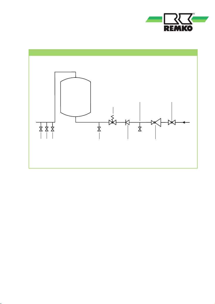
Tank connection according to DIN 1988
Tank
Consumers
In order to ensure the faultless function
of the connection fitting, it may
only be installed in frost-protected
rooms. The discharge of the safety
valve must be open and observable
and the discharge line from the drip
catcher (expansion water funnel) must
be routed to the sewer so that neither
frost nor back-ups from dirt or the like
can cause a fault.
There may not be a shut-off valve or any
other type of flow restrictor installed
between the safety valve and the cold
water feed of the tank.
The safety valve must be set
to a triggering pressure which is below
the nominal pressure of the tank.
Drain
valve
Testing
Safety
valve
Backflow
preventer
After the conclusive connection
of the tank, the cold water supply line
must be rinsed out.
After the water connection is made
and the bubble-free filling of the tank
takes place, the connected fitting must
be tested for function.
When lifting or turning (venting)
the safety valve test knob, the water
must be able to flow out properly
without being hindered by the expansion
tank drain funnel.
In order to check the return flow valve
the shut-off valve is closed and no water
may flow out of the open testing valve.
The testing of the safety valve must take
place in accordance with DIN 1988-8.
valve
Pressure reducing valve
Shut-off valve
If applicable:
11
Page 12
REMKO ETS 300
The operation of the tank takes
place through the hot water valve
of the service water fixture (mixing tap).
Therefore, the tank is under continuous
line pressure. In order to protect the
internal boiler against excessive pressure
when heating up, the accumulating
expansion water is discharged through
the safety valve.
The return flow valve prevents the return
flow of the hot water into the cold
water network during a pressure
drop in the line and thereby protects
the boiler from heating up without
water.
With the shut-off valve the tank can
be disconnected from the cold water
network and thus its pressure and can
be emptied through the drain valve
if necessary.
Circulation connect
Due to significant energy loss,
a circulation connection should
be avoided when possible. If a highly
branched service water network requires
a circulation line, this must be well
insulated and the circulation pump
controlled via a timer and thermostat.
The switching temperature
of the thermostat should be kept low
(45°C).
The circulation connection piece has
an external thread.
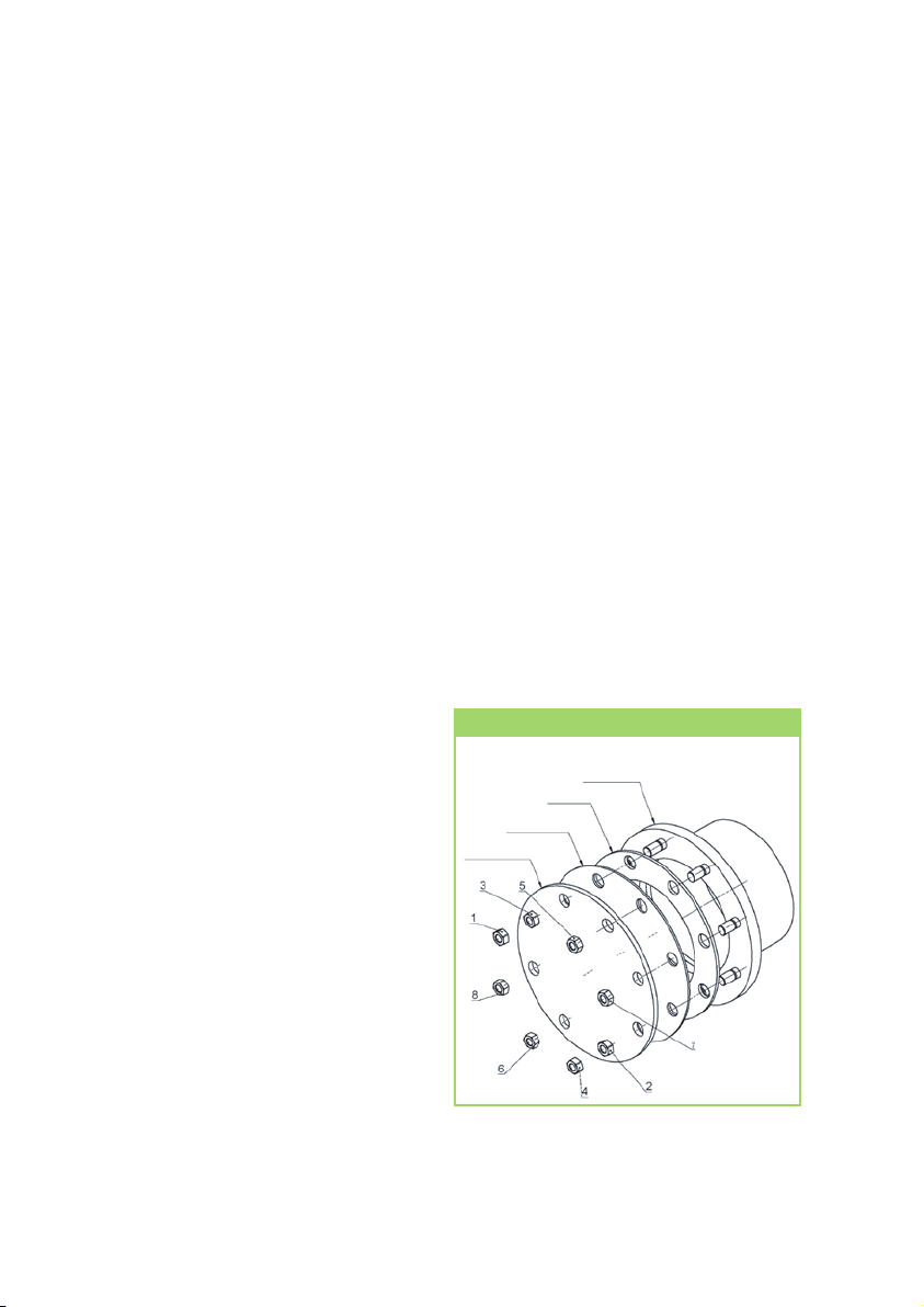
Flange installation port
Depending on the system design, flange
heating cartridges or fin-tube heat
exchangers can be attached at the boiler
flange Ø180 (clear diameter Ø117 mm,
hole circleØ150 mm, 8xM12).
■
Install the flange heating cartridges
in such a way that the sensor of the
temperature regulator is positioned
at the top.
■
First tighten the nuts by hand.
■
Then tighten the nuts,
in the sequence specified below, to
a torque of 20 Nm to max. 25 Nm.
Fitting the flange installation port
Flange ring
Seal
Supporting disc
Flange plate
12
Page 13

Central heating connection
Before being placed into service,
the register must be flushed in order
to remove any soiling (e.g. scale) from
the heating circuit.
Tank with register
The registers (heat exchangers)
built into the tank are suitable for
connecting to a water heater at any
pressure and temperature shown
on the specification label of the hot
water tank.
Forced circulation through a pump
is required.
When installing a tank with a register,
a shut-off member must be installed
in the flow line to prevent back-heating
into the heating circuit when the central
heating and heat pumps are turned off
or in the case of electrical operation.
Corrosion protection
The enamelled boiler is protected
with a standard magnesium rod-type
anode. This anode is self-consuming
and therefore must be inspected every
2 years and replaced as necessary
(for this purpose, see DIN 4753).
A maintenance-free external current
anode (accessory) can be installed
on some models using a reducing
threaded connector IG 5/4"-IG 3/4"
(accessory).
Temperature display, temperature
regulation for charging pump
With the installation of third-party
control units it must be ensured that
the boiler temperature cannot exceed
95°C during operation.
NOTE
Installation should only
be performed by authorised
specialists.
! ATTENTION
However, under no circumstances
may the supply and return lines
be blocked, as otherwise the water
in the register will not have room
to expand and there is a risk
of damage to the heat exchanger!
13
Page 14

REMKO ETS 300
Electrical connection
of the flange heating
cartridge
■
The hot water tank must be filled
with water before being put into
service.
■
A mains connection must be installed
and appropriately fused according
to the circuit diagram affixed
in the terminal box for the unit.
■
A residual current circuit breaker with
a tripping current of I∆N ≤ 30mA
must be located upstream from
the supply circuit.
■
All cables and wires to and from
the unit must be fixed in place.
■
The electrical installation must
have an upstream-connected
isolating device for all poles, with
a contact opening of at least 3mm.
(e.g. in the form of a circuit breaker)
■
The electrical protection
of the equipment should
be implemented according
to the information provided
in the technical data.
! ATTENTION
All electrical installation work
is to be performed by specialist
companies. Disconnect the power
supply when connecting
the electrical terminals.
Before commissioning
Before being placed into service, the
register must be flushed in order to
remove any soiling (e.g. scale) from the
heating circuit.
The smooth pipe heat exchanger
(register) must be rinsed out properly
before the initial installation is carried
out (we also recommend the installation
of a dirt filter). If the smooth pipe
heat exchanger is not used while
operating the tank (e.g. only electric
heating), it must be filled completely
with an appropriate glycol mixture in
order to prevent corrosion from the
accumulating condensation water. The
filled glycol heat exchanger may not
be closed on both sides after filling
(temperature-based pressure expansion).
Before the warm water tank is connected
to the mains electricity supply and put
into service for the first time, it is vital
that it is filled with water.
During initial filling, the discharge valve
must be open. The storage tank is
fully filled, when water which is free of
bubbles starts to run out of the discharge
pipe of the valve.
14
Page 15

Commissioning
NOTE
Commissioning should only be
performed and documented by
specially trained personnel.
1.
Check all connections, even those
which were sealed at the factory
(flange, anode sleeve), for leaktightness.
2
.
Then check all pipes for any leaks
and, if necessary, fix them.
3
.
Test the safety group and valves
between the cold water supply
and hot water tank for proper
function.
During initial filling, the discharge valve
must be open. The warm water tank
is completely full when water, bubble
free, runs out of the valve's discharge
pipe.
Heating the water in the tank causes its
volume to increase.
While heating up, the expansion water
generated in the internal boiler should
drip out of the safety valve.
This dripping is necessary to the function
of the unit, and must not be prevented
by retightening the valves.
4
.
Test the self-actuating shut-off of
the system, any installed electrical
heating attachments and/or the
boiler.
! ATTENTION
The warm water drain pipe as well
as parts of the safety equipment
may become hot.
Once the water has been heated
successfully, the set temperature,
the actual temperature of the water
produced and that shown on any
temperature indicator should
be approximately the same.
15
Page 16
REMKO ETS 300
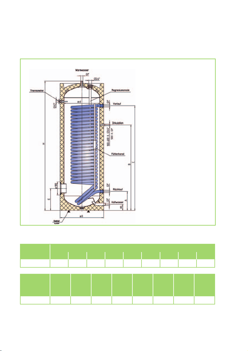
Unit dimensions
ETS 300
We reserve the right to modify the dimensions and design as part of the ongoing technical
Model
ETS 300 1797 610 263 985 1313
Model
ETS 300 1870 450 2.60 17.0 140
* Energy consumption in standby according to DIN 44 532 with 50°C tank temperature and 45°C tap
temperature
** Screw-in heater installation depth
H ø D A B C E F G I
Tip
dimen-
sion
[mm]
Max.
installa-
tion
length
[mm]
development process.
Dimensions in mm
Register
heating
surface
[m²]
Register
capacity
[l]
305
Weight
[kg]
- - -
BEVB*
number
[
kWh/d]
DIN 4708
2.2
NL
acc. to
[-]
10 500
ETE**
[mm]
16
Page 17
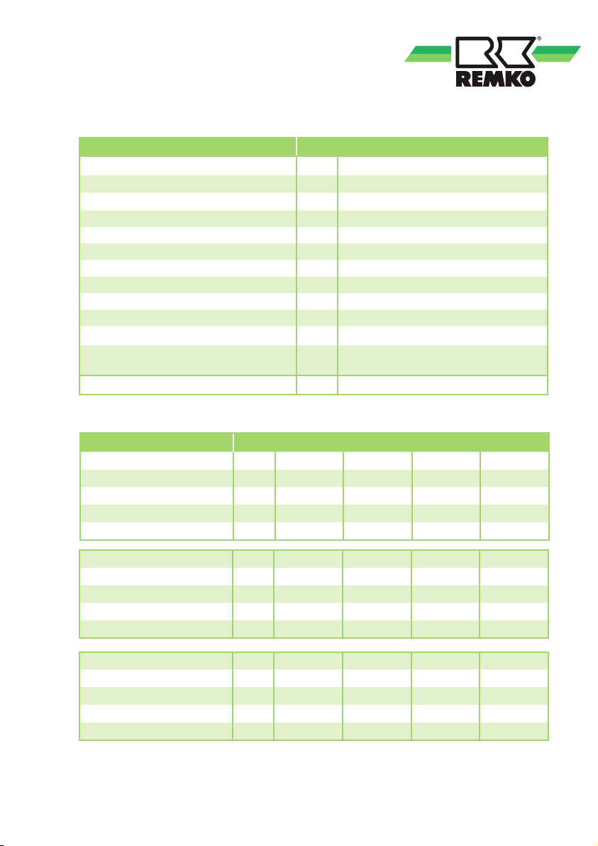
Technical data
Model
Type designation
Capacity (net) L 286
Max. operating temp., drinking water °C 95
Max. operating pressure, drinking water bar
Max. operating temp., hot water °C 100
Max. operating pressure, hot water bar
Max. heating capacity kW
Heat exchanger surface m² 2.6
Register capacity L
BEVB in kW/h / 24h kWh
NL number 10
Max. issue quantity with drawing
at 45°C
Serial number 789C5...
Cycle outputs ETS 300
Supply temperature °C 50 50 50 50
Hot water temperature °C 45 45 45 45
Cold water temperature °C 10 10 10 10
Heating circuit flow rate l/h 500 1000 3000 4500
Cycle output kW
l/min
10.6 15.1 20.9 22.4
ETS 300
ETS 300
10
10
92
17
2.2
37
Supply temperature °C
Hot water temperature °C 45 45 45 45
Cold water temperature °C 10 10 10 10
Heating circuit flow rate l/h 500 1000 3000 4500
Cycle output kW
Supply temperature °C
Hot water temperature °C 45 45 45 45
Cold water temperature °C 10 10 10 10
Heating circuit flow rate l/h 500 1000 3000 4500
Cycle output kW
70 70 70 70
22.9 35.5 55.6 62.1
80 80 80 80
28.3 44.9 73.1 82.2
17
Page 18
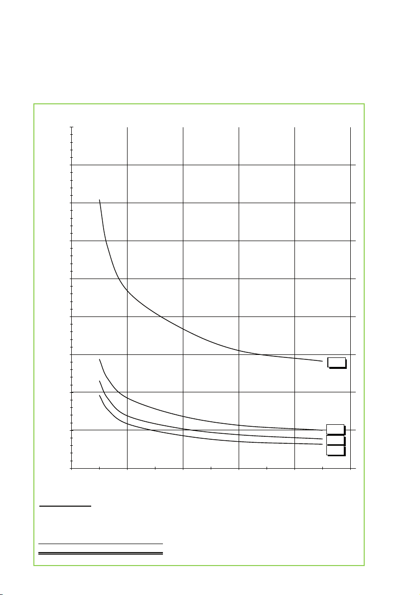
REMKO ETS 300
Aufheizzeiten (45°C) zu HR 300
Ablesebeispiel:
Heizwasserdurchflussmenge 3000 l/h
Heizwasservorlauftemperatur 50 °C
Kaltwassertemperatur 10 °C
Aufheizung von 10 °C auf 45 °C
ergibt eine Aufheizzeit von 31 min
0
10
20
30
40
50
60
70
80
90
0 1000 2000 3000 4000 5000
Aufheizzeit in min
50/45
70/45
80/45
90/45
Heizwasserdurchflussmenge in l/h
Warm up-times at 45°C
18
Page 19

19
Page 20
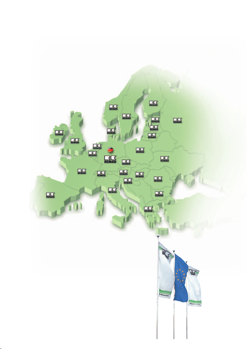
REMKO INTERNATIONAL
... and also right in your neighbourhood!
Take advantage of our experience and advice
REMKO GmbH & Co. KG
Klima- und Wärmetechnik
Im Seelenkamp 12 D-32791 Lage
Postfach 1827 D-32777 Lage
Telephone +49 5232 606-0
Fax +49 5232 606-260
e-mail [email protected]
Website www.remko.de
We reserve the right to make technical changes and provide no warranty as to the accuracy of this data!
 Loading...