

Page 1
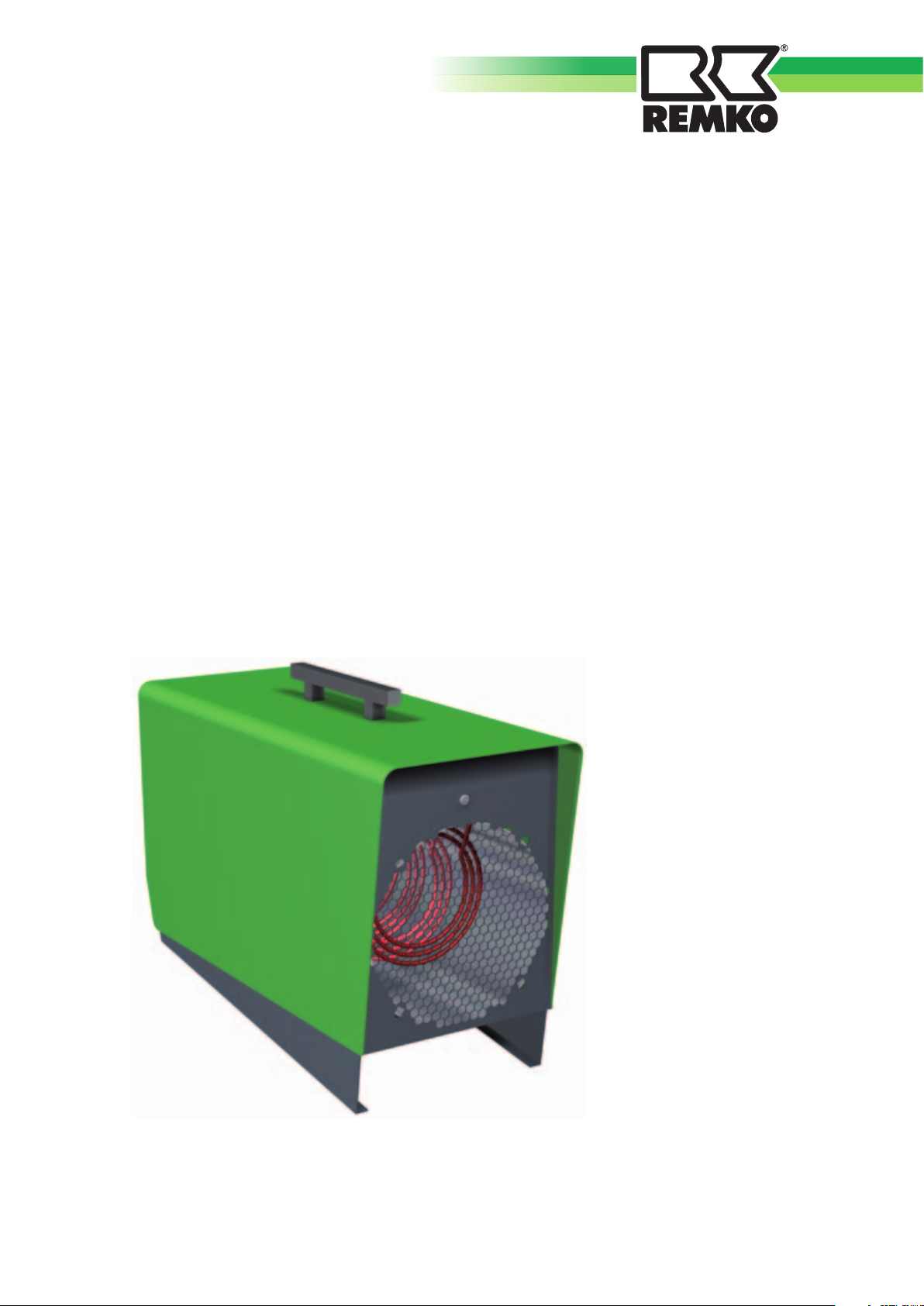
REMKO ELT 9-6
Electric heaters
Operation · Technology · Spare parts
Edition GB – V01
Page 2

Page 3
Contents
Safety information 4
Unit description 4
Commissioning 5
Decommissioning 6
Care and maintenance 6
Troubleshooting 6
Intended use 7
Customer service and warranty 7
Environmental protection and recycling 7
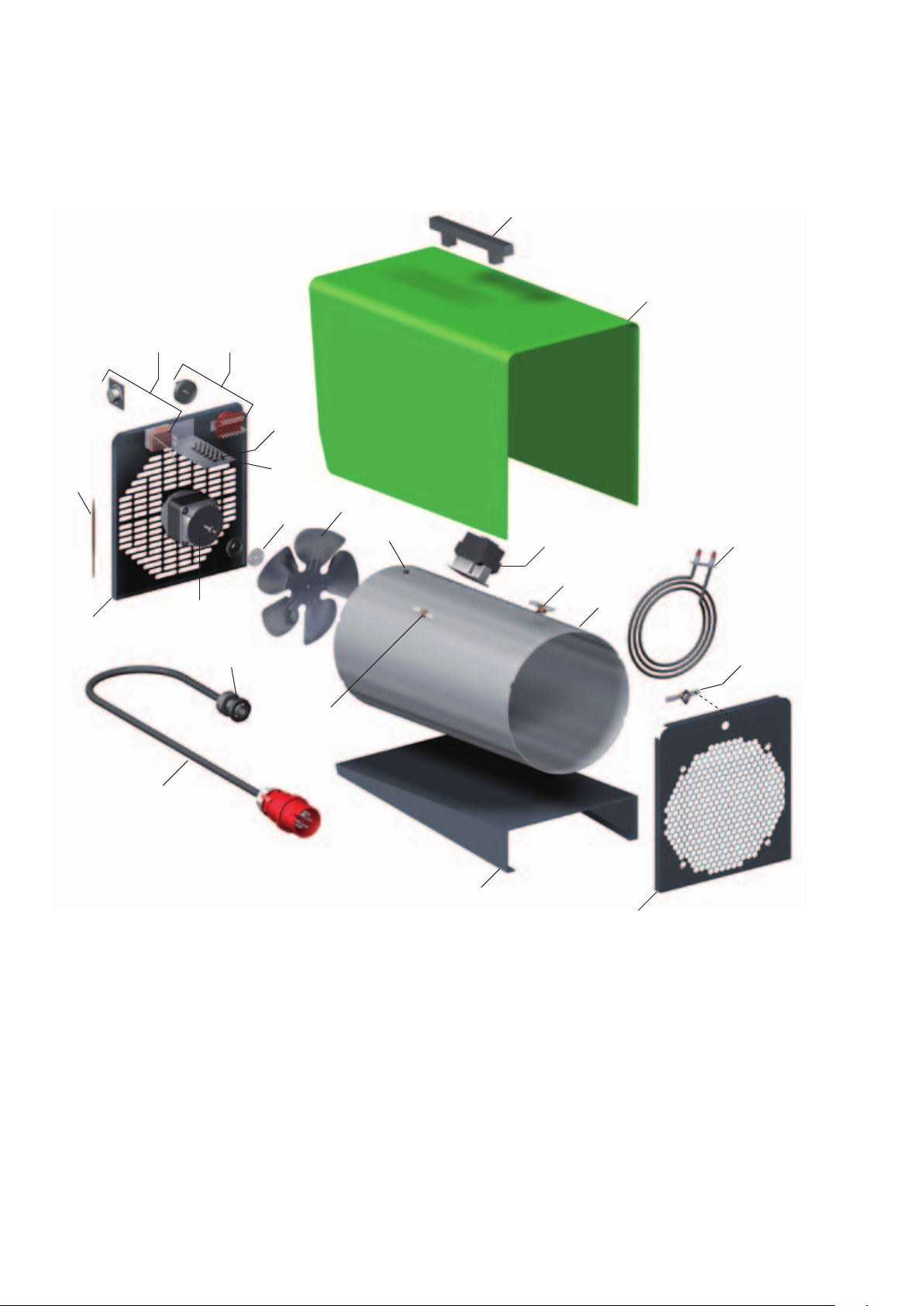
Exploded view 8
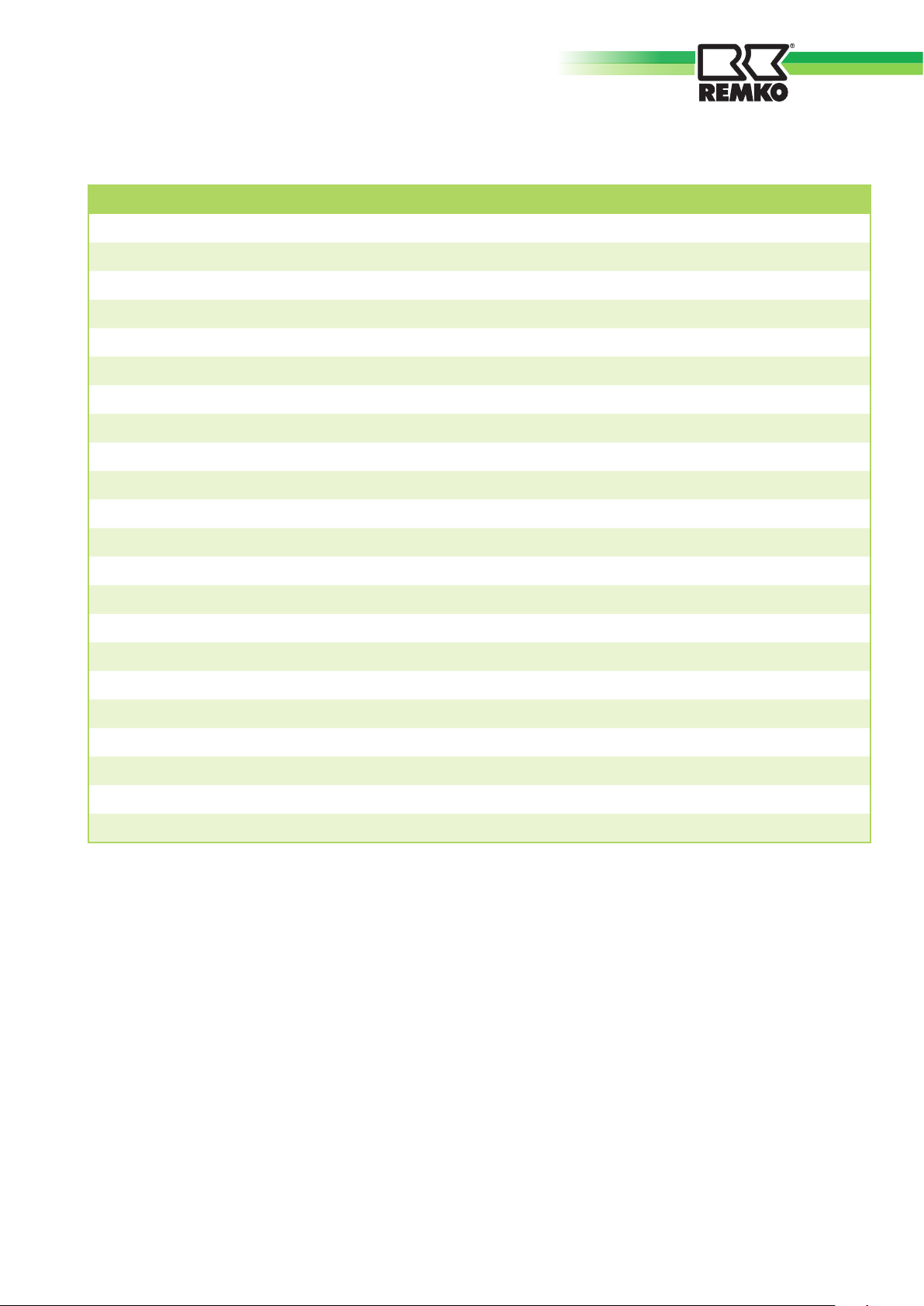
Spare parts list 9
Maintenance log 10
Technical data 11
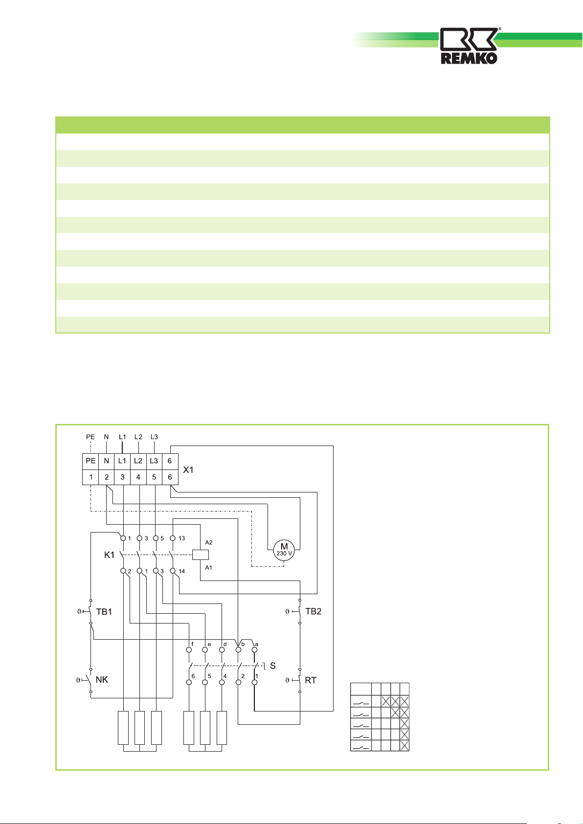
Electrical wiring diagram 11
Made by REMKO
These operating instructions must be read carefully before
commissioning/using the unit!
These instructions are part of the unit and must always be kept near
to the site of installation or on the unit.
Subject to changes; errors and typographical errors excepted!
3
Page 4

REMKO ELT 9-6
Safety information
Operation of the heaters must always take place in compliance with
the local building and fire protection regulations and regulations of the
employers‘ liability insurance associations.
The units were subjected to
extensive material, functional and
quality inspections and tests prior
to delivery. However, the units
may constitute a hazard if used by
untrained personnel, improperly or
not for the intended purpose.
The following information must be
observed
■
Before starting work, persons
responsible for the operation of
the units must check for obvious
defects on control and safety
devices and for the presence
and correct functioning of
protective devices.
Any noticed defects must be
reported to the responsible
supervisor!
■
Units that have defects liable
to affect their reliability must
immediately be switched off.
■ For using the units, the
respective local regulations and
electrical fuse protection ratings
must be observed.
■
Safety distances to flammable
objects must be observed.
■ The air inlet and air outlet vents
must be kept free at all times.
■
The air outlet vents must not
be restricted or pipes or hoses
connected.
■ Never insert foreign objects into
the units.
■
The units must not be covered
whilst in operation.
■
Safety devices must not be
overridden or blocked.
■
The units must not be used near
to baths, showers, swimming
pools, etc.
■
The units must not be used
directly below a wall socketoutlet.
■
The units must not be exposed
to direct water jets.
e.g. high pressure cleaners, etc.
■
Never allow water to enter the
unit.
■
The units must not be installed
and used in locations subject to
fire and explosion hazards.
■
The units must not be installed
and used in oil, sulphur, or saltladen atmospheres.
■
All electrical cables of the units
must be protected against
damage, also damage caused by
animals.
ATTENTION
Safety devices must not be
overridden or blocked.
Unit description
The units are portable electric
heaters for commercial use.
The units are designed solely
for electrical use and for fully
automatic, universal and problemfree operation.
The units have special
encapsulated electric heating
resistors, a low noise and
maintenance axial flow fan, a
safety and cooling thermostat, an
integrated room thermostat and
power cable with earthing pin
plug.
The units comply with the
fundamental safety and health
requirements of the pertinent EU
directives.
The units are reliable and easy to
operate.
The units also have the following
applications:
■
Drying new buildings.
■
Concentrated heating of
outdoor workplaces or for use
in halls and manufacturing
facilities not subject to fire
hazards.
■
Continuous or temporary room
heating.
■
De-icing of machines, vehicles
and non-flammable stored
goods, maintaining the
appropriate safety distances.
4
Page 5
Commissioning
Operation
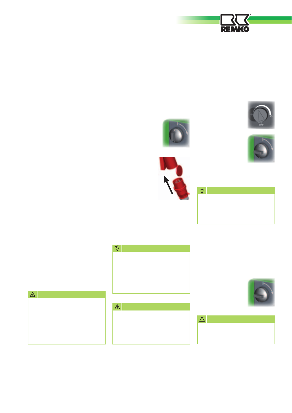
The units can be used for air
heating or only air circulation
depending on the respective mode
selected (switch position 1).
The units have two heat settings
(switch positions 2 and 3).
In order to ensure a constant room
temperature, the units have an
integrated room thermostat.
The thermostat switches off the
heater when the set temperature
is reached and switches it on again
when the temperature falls below
the set value.
The integrated temperature
limiter switches off the unit if the
temperature is excessively high and
switches it on again automatically
after it has cooled down.
After switching off the unit at
the operating switch or room
thermostat, the air supply fan
continues to run for a certain
period of time to cool the heating
resistors
and switches off automatically.
ATTENTION
The unit must never be
disconnected from the mains
supply before the cooling
phase has ended.
Damage attributed to
overheating is not covered by
the warranty.
Operation and monitoring of the
units must be carried out by one
person who has been adequately
instructed in the use of the unit.
1. Check the system voltage for
correspondence with the unit
voltage 400V/3~N/50 Hz.
2. Set the operating
switch to position
“0” (Off).
3. Plug the unit
into a properly
installed mains
socket-outlet.
400V/3~N/50Hz
NOTE
Electrical connection of the
units must be made at a
separate supply point using
a residual-current-operated
circuit-breaker according to
VDE 0100 § 55.
ATTENTION
Only authorised electricians
may extend the connecting
cable taking into account the
rating of the unit, cable length
and use locally.
Heat
The unit operates fully
automatically depending on the
temperature set at the thermostat.
1. Setting the required
room temperature
at the thermostat
2. Set the operating
switch to the
required heat
output - position
“2” = 4.5 kW or
“3” = 9 kW.
NOTE
For optimal operation, the
units should not be operated
at ambient temperatures above
25°C.
Fan
In this position, only the supply air
fan runs. Thermostatic control and
heating are not possible.
1. Set the operating
switch to position
“1” Fan.
ATTENTION
All cable extensions must
be used only uncoiled or
unwound.
5
Page 6
REMKO ELT 9-6
Decommissioning
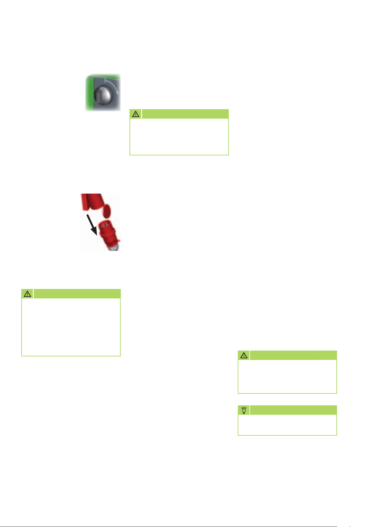
1. Set the operating
switch to
position “0”.
The supply air fan
continues to run to cool down the
units if necessary and switches
off when an adequately low
temperature is reached.
The fan may run several times until
it switches off permanently!
2. The units must
be disconnected
from the supply
if they are not
going to be used
for extended
periods of time.
ATTENTION
The unit must never be
disconnected from the mains
supply before the cooling
phase has ended.
Damage attributed to
overheating is not covered by
the warranty.
Care and maintenance
Regular care and the observance
of a few basic conditions will
guarantee trouble-free operation
and a long service life of the units.
ATTENTION
Before carrying out all work
on the unit, the mains plug
must be disconnected from the
mains socket-outlet.
■
Observe regular care and
maintenance intervals
■
Depending on the particular
operating conditions, the
units should be tested by an
expert for reliable operation
as necessary, however at least
once a year.
■
Keep the unit free of dust and
other deposits.
■
Only clean the units dry or with
a moist cloth.
■
Do not use direct jets of water,
e.g. high pressure cleaners, etc.
■
Do not use caustic cleaning
agents or those containing
solvents.
■
Check the air inlet and air outlet
grilles for clogging.
■
Check the safety and protective
devices at regular intervals.
Troubleshooting
The unit (fan) does not start.
1. Check the local mains fuses.
2. Check the mains plug.
3. Check the operating switch.
4. Check the fan for smooth
operation.
The unit does not heat
1. Set the thermostat to a value
above room temperature.
2. Check function of the
thermostat.
3. Check the operating switch.
4. Check the function of the
contactor.
5. Check the function of the
temperature limiter and inspect
for damage.
If no result is achieved after
carrying out all functional checks,
an authorised service station
should be contacted.
ATTENTION
After completing all work
on the unit, an electrical
inspection must be carried out
according to VDE 0701.
■
Do not damage the sensor and
capillary tube of the thermostat
when removing or fitting the
rear panel of the unit.
6
NOTE
Only authorised electricians
may carry out repairs.
Page 7
Intended use Customer service and
warranty
Due to their design and
equipment, the units are
intended solely for heating and
air circulation in industrial or
commercial use (not for domestic
heating purposes).
Only suitably trained personnel
must operate the units.
The manufacturer is not liable for
any damage attributed to failure
to observe the manufacturer‘s
instructions or applicable statutory
requirements or unauthorised
changes to the units.
A precondition for any warranty
claims is that the dealer or his
customer has completed and
returned the enclosed “Warranty
document” to REMKO GmbH &
Co. KG at the time of sale and
commissioning.
The units were repeatedly tested
at the factory to ensure that they
function correctly.
Nonetheless, if the unit should
have a fault that cannot be
remedied by troubleshooting,
your specialised dealer or contract
partner should be contacted.
Environmental
protection and
recycling
Disposal of packaging
Think of the environment when
disposing of the packaging
material. Our units are carefully
packed for transport and
delivered in sturdy cardboard and
polystyrene packaging.
The packaging materials are
environmentally-friendly and can
be recycled.
By reusing packaging material,
you make a valuable contribution
towards waste reduction and the
conservation of raw materials.
Only dispose of packaging
material at the facilities provided.
NOTE
Use or operation for any other
purpose than that described in
these operating instructions is
not permitted.
Failure to observe this
requirement will result in all
liability being disclaimed and
the warranty rendered invalid.
ATTENTION
Copyright
The copying of this document
in whole or part or use for
any other purpose than that
intended is not permitted
without the prior written
permission of
REMKO GmbH & Co. KG
NOTE
Only authorised specialists
may make adjustments and
carry out maintenance work!
Disposal of the old unit
Our unit production is subject to
constant quality controls.
Only high-quality materials are
used, the majority of which are
recyclable.
Make your contribution towards
environmental protection by
disposing of your old unit in an
environmentally-friendly manner.
Only dispose of your old unit at
an authorised recycling facility or
collection point.
7
Page 8
REMKO ELT 9-6
Exploded view
1
2
14
12
14
11
15
21
16
17
10
19
9
20
18
3
5
6
4
22
8
7
We reserve the right to make changes in dimensions and design in the interest of technical advances.
8
Page 9
Spare parts list
No. Designation EDP No.
1 Transport handle 1101142
2 Outer casing 1101098
2a Outer casing (type INOX) 1111101
3 Cooling thermostat 1104065
4 Temperature limiter 77°C 1101161
5 Inner casing 1101082
6 Heating resistor (1 of 6) 1101083
7 Front panel 1101084
8 Base plate 1101085
9 Fan blade 1101086
10 Driving coupling 1108014
11 Fan motor 1101094
12 Rear panel 1101099
14 Thermostat, complete 1101066
15 Operating switch, complete 1101090
16 Six terminal strip 1101366
17 Mounting plate 1101091
18 Contactor 1101096
19 Temperature limiter 70°C 1101081
20 Protective sleeve 1101304
21 Strain relief 1107944
22 Mains cable with plug 1101026
When ordering spare parts, please always also quote the serial number and unit type (see rating plate) in addition to the EDP number!
9
Page 10

REMKO ELT 9-6
Maintenance log
Unit type: .................................. Serial number: ...................................
1 2 3 4 5 6 7 8 9 10 11 12 13 14 15 16 17 18 19 20
Unit cleaned – externally –
Unit cleaned – internally –
Fan blade cleaned
Protective grille cleaned
Safety devices checked
Protective devices checked
Unit checked for damage
All fixing screws checked
Electrical safety check
Test run
✍
Remarks:......................................................................................................................................................
.............................................................................................................................................................................
.............................................................................................................................................................................
1. Date: ..............
..............................
Signature
6. Date: ..............
..............................
Signature
11. Date: ............
..............................
Signature
16. Date: ............
..............................
Signature
2. Date: ..............
..............................
Signature
7. Date: ..............
..............................
Signature
12. Date: ............
..............................
Signature
17. Date: ............
..............................
Signature
3. Date: ..............
..............................
Signature
8. Date: ..............
..............................
Signature
13. Date: ............
..............................
Signature
18. Date: ............
..............................
Signature
4. Date: ..............
..............................
Signature
9. Date: ..............
..............................
Signature
14. Date: ............
..............................
Signature
19. Date: ............
..............................
Signature
5. Date: ..............
..............................
Signature
10. Date: ............
..............................
Signature
15. Date: ............
..............................
Signature
20. Date: ............
..............................
Signature
10
The unit must only be serviced by authorised specialists in compliance with the statutory requirements.
Page 11
Technical data
R1 bis R3 R4 bis R6
Series ELT 9-6
Nominal heat output kW 9.0
Switchable heat output kW 2 x 4.5
Air capacity m3/h 600
Power supply V/Hz 400/3~N/50
Max. nominal current A 13.2
Max. power input kW 9.7
Fuse protection (local) A (slow-acting) 16
Sound pressure level LpA 1m 1) dB (A) 53
Dimensions: Length mm 510
Width mm 300
Height mm 455
Weight kg 14.7
1)
Noise measurement DIN 45635 - 01 - KL 3
Electrical wiring diagram
Legend:
K1 = Contactor
M = Motor
NK = Cooling thermostat
R1 to R3 = Heating resistors for setting 1
R4 to R6 = Heating resistors for setting 2
RT = Thermostat
S = Operating switch
TB1 = Temperature limiter
TB2 = Temperature limiter
X1 = Terminal strip
Switching level for operating switch [S]
We reserve the right to make changes in dimensions and design in the interest of technical advances.
S 0 1 2 3
a
b12
d
4
e
5
f
6
11
Page 12
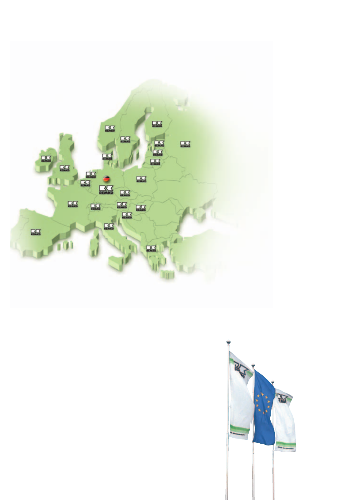
REMKO INTERNATIONAL
… and also right in your neighbourhood!
Make use of our experience and advice
REMKO GmbH & Co. KG
Air conditioning and heating technology
Im Seelenkamp 12 · 32791 Lage
PO Box 1827 · 32777 Lage
Tel. +49 5232 606-0
Fax +49 5232 606-260
E-mail [email protected]
Website www.remko.de
Hotline
Air conditioning and heating technology
+49 5232 606-0
Export
+49 5232 606-130
Advice
We keep the specialist knowl-
edge of our advisers continu-
ously up-to-date with intensive
training. This has earned us a
reputation as more than just a
good, reliable supplier:
REMKO, a partner
who is here to help solve prob-
lems.
Distribution
REMKO provides not only a
well-developed distribution
network in Germany and abroad,
but also unusually highly skilled
professionals in distribution.
REMKO staff in the field are
more than mere salespeople:
they must primarily act as
advisers in air conditioning and
heating technology for our
customers.
Customer Service
Our units work precisely and
dependably. Should a failure
occur, however, REMKO cus-
tomer service will rapidly be at
your side. Our comprehensive
network of experienced dealers
guarantees quick and
reliable service.
Subject to technical modifications, no responsibility taken for the correctness of information!
 Loading...