

Page 1
REMKO ELT 18-S / ELT 18-S E
Electric Heaters
Operation
Technology
Spare Parts
Edition GB – M12
REMKO - powerful like a bear.
Page 2

Page 3
Operating instructions
Make sure to read these instructions carefully before starting/using the unit!
Our guarantee will become void when the unit supplied by us is used and
installed for inadequate purposes, or maintained incorrectly, etc.,
or if it is changed without our prior consent.
Subject to alterations!
Mobile
Electric Heaters
Contents Page
Safety Instructions 4
Description of device 4
Starting 4
Unit shut down 5
Maintenance and service 5
Hot air distribution 6
Troubleshooting 7
Always keep these operating instructions near or on the unit!
G
Contents Page
Service and guarantee 7
Technical data 7
Exploded view 8
Spare part list 8
Wiring diagram 10
Maintenance log 11
G
3
Page 4
Safety Instructions
REMKO electric heaters will provide you with high utility
and long life thanks to our extensive material, function
and quality controls. Dangers may arise nevertheless if
the unit is used by persons not familiar with its operation
or if the unit is not used for its intended purpose.
◊ The persons charged with the operation of the units
have to check these before starting work as to visible
defects of the operation and safety devices, as well as
to make sure that no protective devices are missing.
In the case of faults the supervisor is to be informed.
◊ In the case of faults which endanger the safe opera-
tion of the units, the units are to be stopped!
◊ During the operation of the units the applicable local
regulations are to be observed and the relevant
safety measures to be taken.
◊ Make sure that the prescribed safety distances from
combustible objects are observed!
◊ A free air suction and air blow off must be ensured.
◊ Never place foreign objects into the unit.
◊ Do not cover the units during operation.
◊ The units may not be operated near bath tubs, show-
ers, swimming pools, etc.
◊ The units may not be operated directly beneath a wall
socket.
◊ The units may not be exposed to direct water jets.
◊ Make sure that no water penetrates inside the units.
◊ The units may not be operated in rooms which are
endangered by explosions.
◊ Protect all electric cables outside the units from
damage (e.g. caused by animals).
Connecting cable extensions may be laid exclusively by authorized electricians based on the unit
capacity, cable length and taking the local terms of
G
use into account.
Application
◊ Drying of new buildings, spot heating of working places
outside or in fire-proof halls and production places.
◊ Permanent or temporary heating of rooms.
◊ Defrosting of machines vehicles and fire-proof storing
goods with keeping the prescribed distance of safety.
Working of device
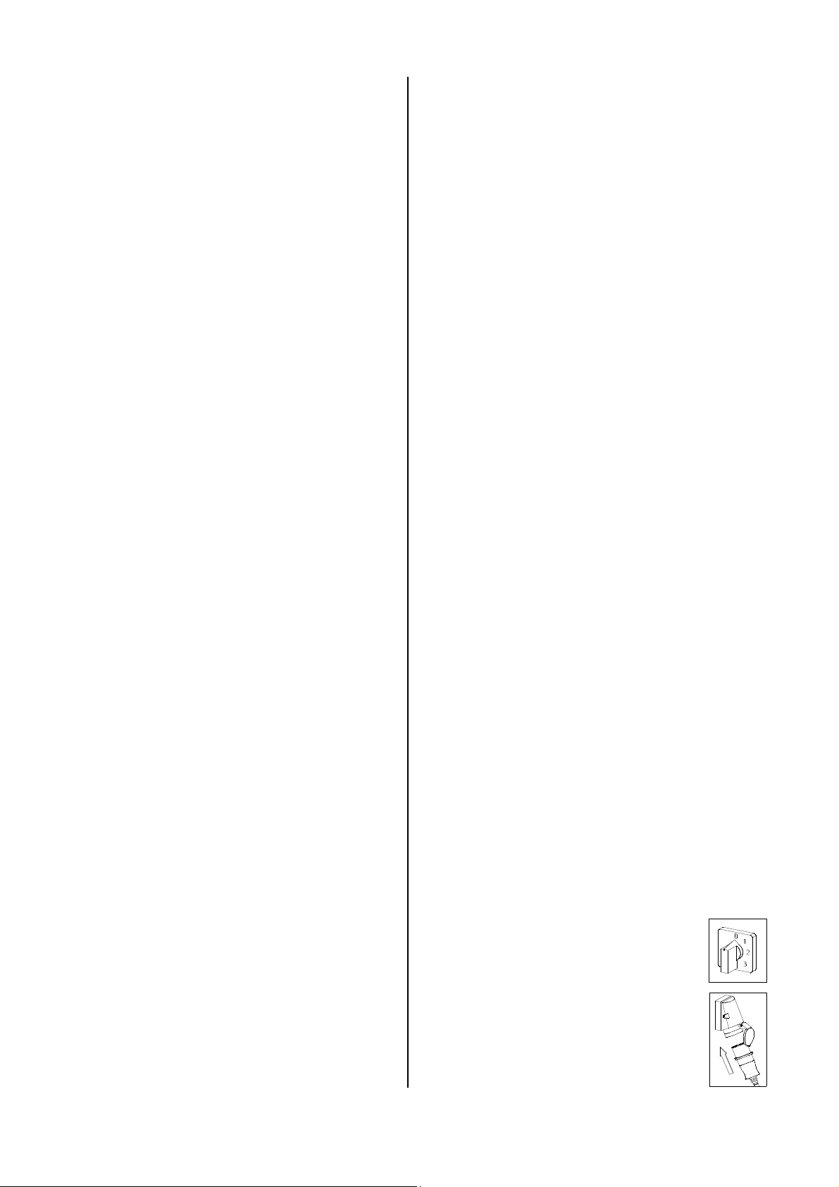
The units are equipped with a 4-stage operating switch.
In the first stage only the supply air fan is operated and
the units can be used for air circulation.
In the 2nd – 4th. stage the heating elements are acti-
vated and hot air is discharged.
The units can be operated with a room thermostat
(accessories) which is ready to be plugged in, to ensure
a constant room temperature. When the pre-selected
temperature has been reached, the thermostat stops
the heating operation to restart it when the temperature
has fallen below the set value.
When the units have been switched off by the operating
switch or the room thermostat, the supply air fan continues running for a certain time to cool down the heat exchanger, and then it stops automatically.
Starting
A well trained person is to be charged with the operation
and control of the units.
The electric connection of the units is to be carried
out via a special supply point with fault current
G
safety switch.
Description of Device
The units are operating with electric energy. They are specially designed for the usage of hot air hoses and for a fully
automatic, all-purpose and simple application.
The units are equipped with capsuled electrical heating
elements, noiseless maintenance-free axial fans, safety
and after-cooling thermostat, thermostat socket and
connecting cable with plug.
The units are in accordance with the basic safety and
health requirements of the relevant EC – regulation.
The units are handled simply and are safe in operation.
4
1. Check the main voltage is in accordance with the
unit voltage.
Electrical connection 400 V 3 / N ~
Frequency 50 Hz
Fuse protection (required) 32 A (inert)
2. Put operating switch into position "0".
3. Connect the unit-plug to an adequate
mains socket.
Page 5
Switch settings
Unit Shut Down
Operating switch
ELT 18-S
Ventilation
In this position only the supply air fan runs. The thermo-
static regulation and the heating operation is not possible.
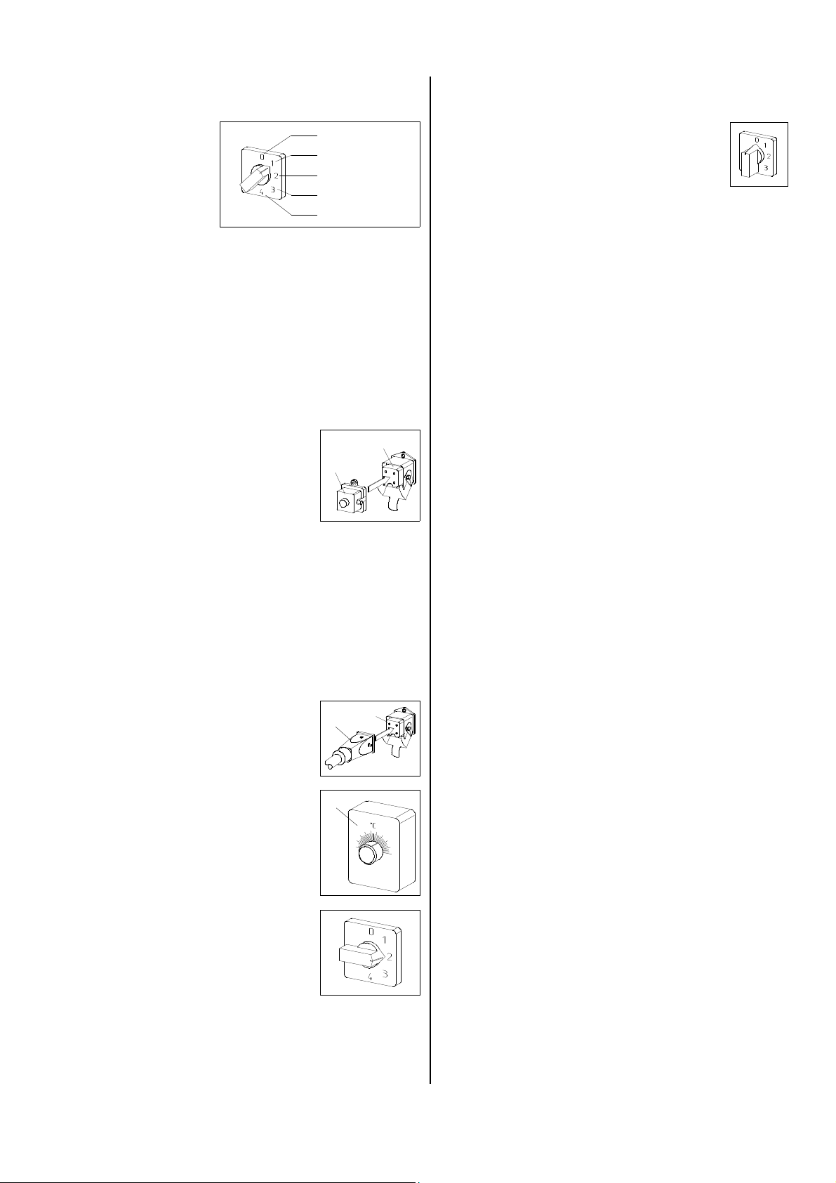
1. Put the operating switch into position “1”.
Heating without room thermostat
The unit runs under continuous duty.
1. Plug the supplied bridge circuit
plug 2 into the thermostat socket
1 of the unit.
2. Put operating switch into desired
position (2 or 3 or 4) depending
on the desired heating capacity.
For optimum unit operation, the device should not
be operated at an ambient temperature above 25 °C.
G
off
ventilate
1. stage heating
2. stage heating
3. stage heating
1
2
1. Put operating switch into position “0”.
OFF
Attention, important hints to the after-cooling phase.
The air supply fan continues running to cool down the
unit and then stops later.
Fan can start several times before final switching off.
Never interrupt (except in emergency situations)
the connection to the mains before the end of the
whole after-cooling phase.
G
Our guarantee does not cover damages caused
to the unit by overheating.
Maintenance and Service
Regular maintenance and the observation of some basic principles is important to ensure a long service life
and a trouble-free operation of the unit.
Prior to starting any work make sure to pull the
mains plug out of the mains socket!
G
Heating with room thermostat
The unit runs fully automatically and is dependent on set
temperatures.
1. Remove the bridge circuit plug 2.
2. Plug thermostat plug 3 of the room
thermostat (accessories) into the
thermostat socket 1.
3. Put room thermostat 4 in a suitable
place.
The thermostat sensor may not be
exposed directly to the hot air current and not fixed directly on a cold
surface.
4. Pre-select desired room temperature on the room thermostat.
5. Put operating switch into desired
position (2 or 3 or 4) depending on
the desired heating capacity.
If the temperature at the blower aperture rises
above 100° C the heating operation is stopped.
G
1
3
4
Please pay attention to the following points:
◊ The unit is to be maintained and cleaned in regular
intervals.
◊ The unit is to be kept free from dust and other de-
posits and is to be cleaned only with a dry or humid
cloth.
Do not use water jet.
◊ Do not use any aggressive cleaning agents or those
which are harmful or environmentally unfriendly.
◊ Do not use cleaning agents which contain solvents.
◊ Only use suitable cleaning agents to remove ex-
treme dirt.
◊ Check safety devices regularly.
Check protective suction and blower grids regularly
and clean, when necessary.
◊ Do not damage the sensor and capillary tube of the
thermostat when the protective blower grid is installed or removed.
◊ According to the terms of use the units are to be
checked as to their perfect operation by an expert
when necessary, but at least once a year.
Please carry out an electrical safety test after having finished service on the unit.
G
5
Page 6
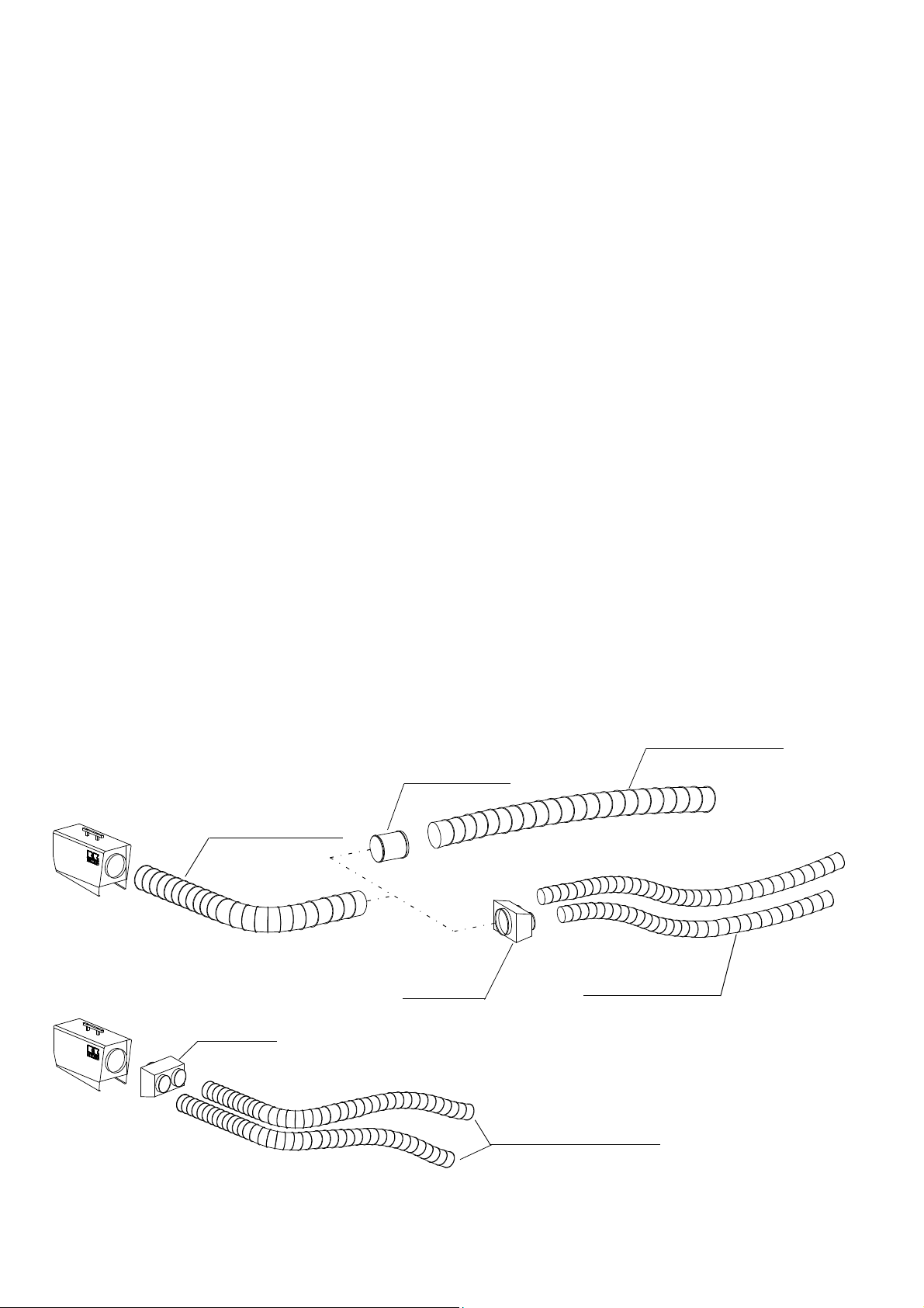
Hot air distribution
The unit is equipped with a high efficiency axial fan.
The high efficiency axial fan permits operation with hot
air hoses in different variants to transport the warmed
air exactly and efficiently to the specific place.
Please observe the following instructions when hot air
hoses are to be fitted:
◊ Please use exclusively those hot air hoses (acces-
sories) which have been approved by our company.
◊ The internal overlapping at the seams must to point
at air direction.
◊ Make sure that the hot air hoses are safely fastened
to the outgoing air connection piece.
◊ The pipes and hoses may not have sharp kinks and
bends in order to avoid heat accumulation.
◊ If the temperature at the blower aperture rises above
100° C the heating operation is stopped.
◊ A free air blow off must be ensured.
Due to the special high efficiency axial fan, the unit
should not be operated without hot air hoses.
G
Possible variations: (max. length 15 m)
Hot air hoses with ø 305
maximal 2x 7,6m
with hose extension
Hot air hoses with ø 203
maximal 2x 7,6m
with attachment
Hot air hoses ø 305 in combination with ø 203
maximal 1x 7,6m ø 305 plus 2x 7,6m ø 203
with attachment
REMKO spare parts:
Hot air hose ø305, 7,6m with sealing belt
EDV–No. 1099502
Hot air hose ø203, 7,6m with sealing belt
EDV–No. 1099501
Attachment with 2 outlets à ø203
EDV–No. 1099550
Hose extension ø305 with 2 sealing belts
EDV–No. 1009760
Assembly examples
Hot air hose ø305
Attachment
hose extension
Attachment
Hot air hose ø305
Hot air hose ø203
Hot air hose ø203
6
Page 7

Troubleshooting
Prior to starting any work make sure to pull the
mains plug out of the mains socket!
Setting and maintenance is to be carried out
G
only by authorised experts!
Unit (fan) does not start:
1. Check main fuse
2. Check connecting cable with plug
3. Check operating switch
4. Check slight drifting of fan (motor)
Unit does not heat
1. Check operating switch
2. Check contactor
3. Check function of temperature limiter resp. check
capillary tubing (if damaged)
4. Check if thermostat plug resp. bridge circuit plug is
coupled
5. Check thermostat-operation: thermostat must be set
higher than the room temperature
Should the unit still not be working despite these checks,
please contact an authorised service centre.
Service and Guarantee
Any claims under guarantee regarding materials can be
accepted only when the orderer or his customer has
filled in completely the “guarantee certificate” which is
enclosed with every REMKO-heater and has returned it
to REMKO GmbH & Co. KG in due time after the unit’s
sale and commissioning.
The units are factory tested on faultless function. If any
failures occurs though which cannot be eliminated by the
operating person, please contact your dealer or contact
person.
An operation/use other than that indicated in these
instructions is prohibited!
In the case of non-observation we will not be held
G
responsible and our guarantee will become void.
Correct usage
The units are to be used only for heating and ventilation
purpose in industrial or commercial application because
of their construction and equipment.
If specification of the manufacturer or legal regulations,
are not followed or if unauthorised changes are made
on the unit, the manufacturer is not liable for resulting
damages.
Technical Data
Model
Nominal heat output kW 18
Switchable heat output kW 3 x 6
Air output m³/h 1600
Electrical connection V 400/3~
Frequency Hz 50
Rated current max. A 27,8
Power consumption max. kW 18,5
Fuse protection (required) A (inert) 32
Sound pressure level L
Sound pressure level L
Dimensions Length mm 750
Width mm 335
Height mm 500
Weight kg 28,7
1) noise measuring (without hot air hose) DIN 45635 - 01 - KL 3
2) noise measuring (with hot air hose) DIN 45635 - 01 - KL 3
pA 1m
pA 1m
1)
dB (A) 72
2)
dB (A) 68
ELT 18-S / 18-S E
7
Page 8
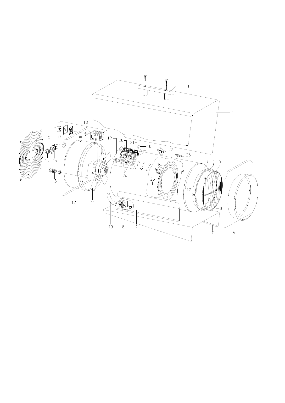
Exploded View
We reserve the right to make modifications in dimensions and construction in the interests of technical progress.
8
Page 9

Spare Part List
No. Description Ref.-No.
1 transport handle 1101142
2 outside casing ELT 18-S 1107920
2a outside casing ELT 18-S E (stainless steel) 1107919
3 inside casing with blow-out cone 1107953
4 cone gasket 1107954
5 blow-out protection grille 1101353
6 front panel with blow-out connection 1107930
7 base plate 1107950
8 temperature limiter with sensor 1107960
9 support bracket 1107922
10 protection hose 1107915
11 fan motor with blade 1107992
12 rear panel 1107931
13 traction relief 1107961
14 thermostat socket, cpl. 1101018
15 bridge circuit plug 1101019
16 air suction grille 1107994
17 protection socket 1101304
18 operating switch, cpl. 1107993
19 capacitor 1102716
20 terminal strip, 5 fold 1107952
21 terminal strip, 3 fold 1101373
22 temperature limiter 1101161
23 recool thermostat 1104065
24 contactor 1101025
25 heating element 1107998
not shown. connecting cable with plug 1107962
thermostat plug 1101020
When ordering spare parts it is necessary to indicate EDV-No. and machine no. (see data plate)!
9
Page 10
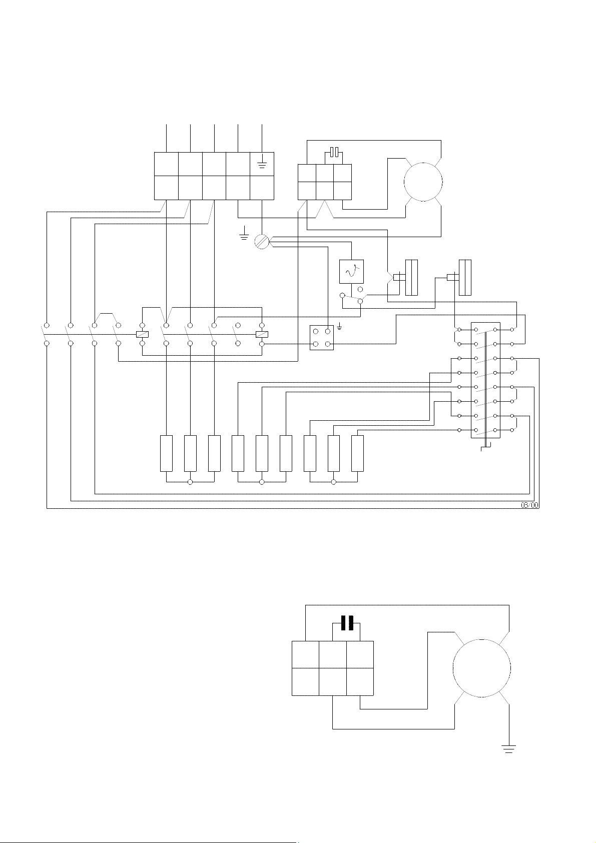
Wiring Diagram
400 3/N ~ 50Hz
L1 L2 PE L3
L1 L2 L3 N
KL
1
N
2 5 3 4
C
C2 M1 C1
KLM
8 6 7
M
1~
NK TB STB
K2 K1
1 2 3 4 5 6 13
14
HW
KL = terminal strip
C = capacitor
A2
1 2 3 4 5 6 13
A1
14
C
A2
A1
2
1
3 2
RT
Wiring diagramm fanmotor
L1
V2
L2
V4
L3
V6
M
H
V1
V3
V5
S
KLM = terminal strip fanmotor
M = fanmotor
STB = temperature limiter (with sensor)
NK = recool thermostat
TB = temperature limiter
K1 = contactor 1
K2 = contactor 2
RT = thermostat socket
S = operating switch
HW = heating element
10
M1 C1 C2
6 7 8
C
KLM
blau
braun
M
1~
schwarz
Page 11
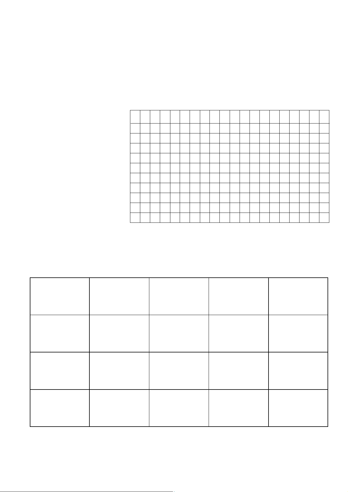
Maintenance Log
Model: ................................ Model No: ......................................
1 2 3 4 5 6 7 8 9 10 11 12 13 14 15 16 17 18 19 20
Clean unit -surfaceClean unit -interiorClean protection grille
Clean fan blade
Check safety facility
Check protection guards
Check unit for damage
Check fastening screws
Test run
Electric safety-inspections
Remarks: ......................................................................................................................................................................
......................................................................................................................................................................................
1. Date: ...................... 2. Date: ...................... 3. Date: ...................... 4. Date: ...................... 5. Date: ......................
.................................. .................................. .................................. .................................. ..................................
Signature Signature Signature Signature Signature
6. Date: ...................... 7. Date: ...................... 8. Date: ...................... 9. Date: ...................... 10. Date: ....................
.................................. .................................. .................................. .................................. ..................................
Signature Signature Signature Signature Signature
11. Date: .................... 12. Date: .................... 13. Date: .................... 14. Date: .................... 15. Date: ....................
.................................. .................................. .................................. .................................. ..................................
Signature Signature Signature Signature Signature
16. Date: .................... 17. Date: .................... 18. Date: .................... 19. Date: .................... 20. Date: ....................
.................................. .................................. .................................. .................................. ..................................
Signature Signature Signature Signature Signature
Setting and maintenance work is to be carried out only by authorised specialists!
11
Page 12

REMKO GmbH & Co. KG
Klima- und Wärmetechnik
D-32791 Lage • Im Seelenkamp 12
D-32777 Lage • PO Box 1827
Phone +49 (5232) 606 - 0
Fax +49 (5232) 606260
 Loading...