

Page 1

REMKO ATK 50-S
Automatic oil heater
with built-in oil burner,
tank and exhaust gas connection
Operation · Technology · Spare parts
Edition GB-I02
Page 2

Page 3

Contents
Safety notes 4
Environmental protection and recycling 4
Unit description 5
Installation instructions
Exhaust gas routing 7
Transport 7
Commissioning 8-9
Shutdown 9
Care and maintenance 9-11
Exploded view of the unit 12
Spare parts list 13
Troubleshooting 14
Technical data 15
Electrical wiring diagram 15
6-7
Carefully read this operating manual prior to commissioning
or using the units!
This manual is an integral part of the unit and must always
be kept in the vicinity of the installation location or on
the unit itself.
Subject to modifications; no liability accepted for errors or misprints!
3
Page 4

REMKO ATK
Safety notes
Environmental
protection and
Always observe the respective local building code and fire prevention
guidelines as well as the guidelines of the accident prevention and
insurance associations when using the equipment. Disposing of packaging
The units have been subjected
to extensive material, functional
and quality inspections prior to
delivery. However, dangers can
arise from the units if they are used
improperly or not as intended by
untrained personnel!
The following notes must be
observed in full:
■
The power plug must be pulled
out of the mains socket before
maintenance and repair work
■
The units may only be operated
by persons that have been
instructed in their operation
■
The units must be installed and
operated in such a way that
personnel are not endangered
by exhaust and radiant heat
and that no fires may occur
■
The units must then only
be operated in areas where
the units can be supplied with
an adequate amount of air for
combustion
■
Without exhaust routing,
the units may only be operated
in well ventilated spaces.
Personnel must not remain in
the installation area.
Appropriate prohibition
signs must be erected at
the entrances!
■
Set the units down on a
level and non-combustible
base
■
The units may not be installed
or operated in potentially
flammable or explosive
environments
■
The units must not be installed
or operated in atmospheres
containing oil, sulphur or salt
■
A safety zone of 1.5 m must be
maintained around the units,
incl. to non-combustible items
■
The protective grid of the
intake must always be kept free
of dirt and loose objects
■
Never insert foreign objects into
the unit
■
The units must not be exposed
to direct jets of water e.g.
pressure washers, etc.
■
All electrical cables for the
units must be protected against
damage (e.g. by animals etc.)
■
Safety devices must not be
bypassed or disabled
■
According to its design,
permanent, fixed unit
installation is not intended for
this unit type
When disposing of packaging
material, please consider our
environment.
Our units are carefully packed
and delivered in stable transport
packaging and, if applicable, on a
wooden pallet.
The packaging materials are
environmentally friendly and can
be recycled.
By recycling packaging materials,
you make a valuable contribution
to the reduction of waste and
conservation of raw materials.
Therefore, only dispose of
packaging material at appropriate
collection points.
Disposal of the old unit
The manufacturing process for
the units is subject to continuous
quality control.
Only high-grade materials are
processed, the majority of which
are recyclable.
You also contribute to
environmental protection by
ensuring that your old equipment
is only disposed of in an
environmentally-friendly manner.
Therefore, only take the old
unit to an authorised recycling
business or to an appropriate
collection point.
recycling
4
Page 5
Unit description
The units are portable, directly
fired fan-assisted heaters (WLE)
with heat exchanger and exhaust
gas connections exclusively for
commercial applications.
The units can be directly fired with
EL heating oil or diesel fuel and
may be operated with or without
an exhaust gas duct.
The units are equipped with a
4-part fuel filter system, highpressure atomisation burner
with optical flame monitoring,
low-maintenance axial fan, room
thermostat socket and mains cable
with earthed safety plug in IP 67
design.
The filler cap is equipped with
a surge-resistant venting valve.
This generates a negative pressure
in the fuel tank during operation
(slight hissing when opening
the filler cap).
The units conform to the
fundamental health and safety
requirements of the appropriate EU
stipulations. The units are reliable
and easy to operate.
The units may be used for the
following (inter alia) :
■
Heating tents/marquees
■
Spot heating workplaces
in open, non-flammable
manufacturing facilities and
halls
■
Temporarily heating enclosed
and open spaces
■
De-icing machines, vehicles and
non-combustible warehoused
goods
■
Maintaining the temperature of
frost-sensitive goods
Operating sequence
The supply air fan switches on
once the units are switched on in
heating mode or if heat is required
(fully automatic unit operation
with room thermostat).
The solenoid valve opens the fuel
supply to the oil nozzle following
burner pre-ventilation.
The fuel atomised under high
pressure is enriched with a
quantity of oxygen appropriate to
the heating capacity and ignited by
an electrical spark.
As soon as a flawless flame has
been generated, the automatic
burner begins optical flame
monitoring.
Warm air is blown out after a short
period of time.
The automatic burner executes all
unit functions fully automatically
and ensures reliable monitoring.
In the event of malfunctions or an
unstable or extinguished flame,
the automatic burner switches
the units off.
The unit's fault lamp will light up
in this case. The units can only be
restarted after manually resetting
the automatic burner.
After switching off the units via
the operating switch or the room
thermostat, the supply air fan runs
to cool the combustion chamber
for a certain time and then
switches off automatically.
Depending on the heat
requirement, the operating
sequence described is repeated
fully automatically when in
thermostat mode.
Safety temperature limiter
(STB)
The heating function is
permanently interrupted by
the safety temperature limiter
(STB) in the event of the units
overheating or malfunctioning.
In the event that the STB is
triggered, a fault shutdown of
the automatic burner occurs.
A manual reset of the STB can only
be implemented after the units
have cooled down.
ATTENTION
If the safety temperature
limiter has been triggered,
the cause of the malfunction
must be identified and rectified
before a reset is performed.
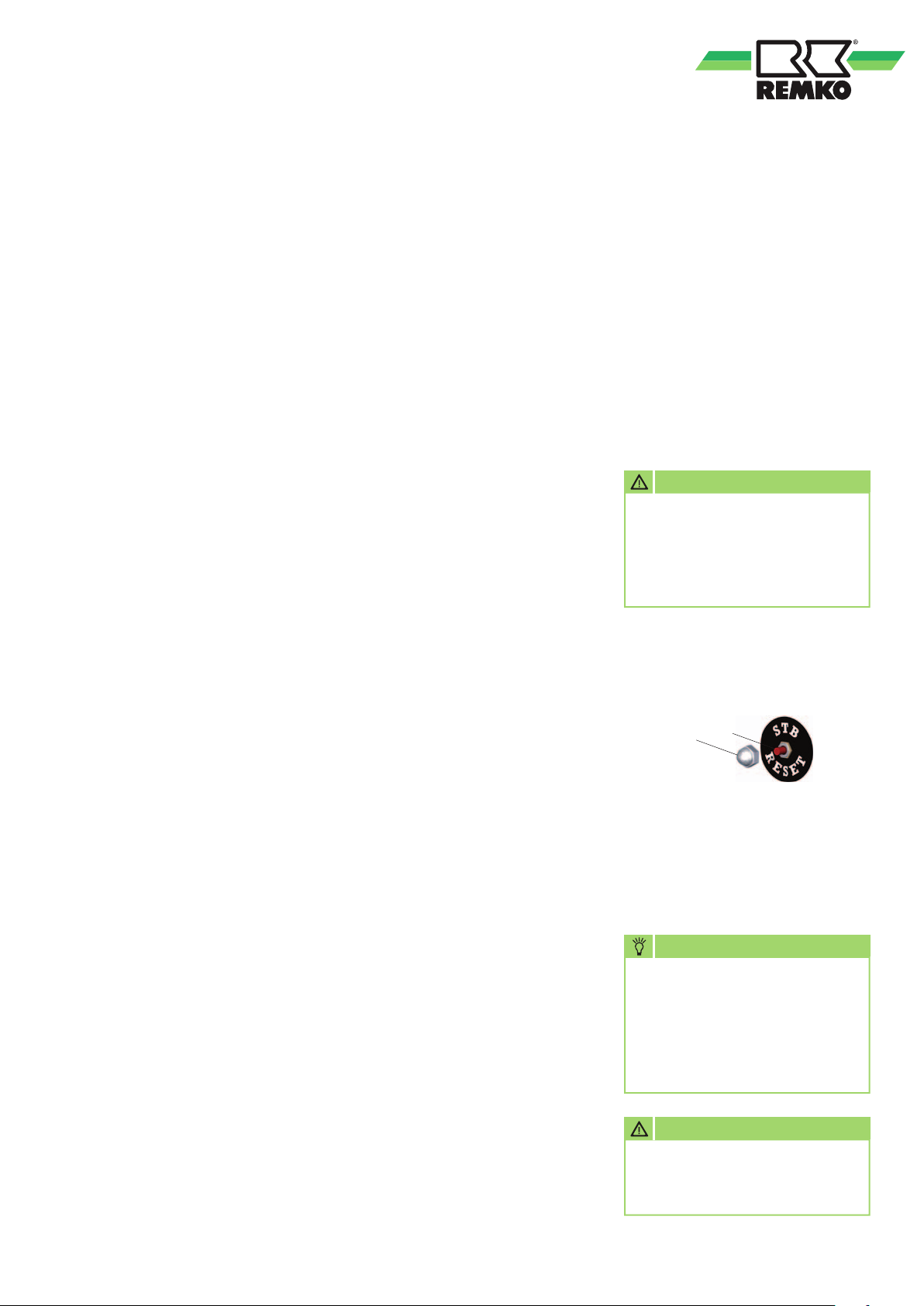
The resetting of the STB is
implemented by actuating
the reset key 2.
1. Unscrew the protective cap 1.
2
1
2. Carefully press in the reset key
2 with a suitable tool.
3. Screw the protective cap 1 back
on again.
4. Reset the automatic burner.
NOTE
In order to prevent a renewed
exceedance of the triggering
temperature the operating
conditions of the unit should
be checked before resetting
the STB.
ATTENTION
Safety devices must not be
bypassed or disabled.
5
Page 6

REMKO ATK
Installation instructions
The safety regulations of the accident
prevention and insurance associations,
the respective regional building
regulations and the combustion
appliances regulations apply to
operation of the unit.
NOTE
Overpressure and underpressure
in the installation area
should be avoided as this will
inevitably lead to combustionrelated faults.
■
Ensure that there is an adequate
fresh air supply appropriate to
the respective forced-air burner
capacity (see name plate)
Outdoor installation
■
Operation of the units must
not present a hazard or
unreasonable loading
■
The unit operator must
ensure that it is impossible
for unauthorised persons to
manipulate either the unit or
the power supply
■
To prevent damage due to
inclement weather, units
installed outdoors must be
adequately protected
Installation in enclosed, well
ventilated areas without
exhaust gas connection
■
Operation of the units is
permissible only if the minimum
air quantity for combustion is
supplied
■
Reliable extraction of
the combustion gases must
be guaranteed in all cases in
order to exclude impermissible
contamination of the room air
with hazardous substances
Fresh air is fed from below.
Exhaust gases are routed
upwards
Room heating
■
The units may only be operated
for room heating with a room
thermostat (accessories)
■
The fresh air supply required
for trouble-free combustion
must be ensured. It is practical
to have the fresh air supply
provided by windows and
doors or through appropriately
dimensioned openings in
the outside wall
Safety distances
■
In order to guarantee safe
operation and maintenance
of the units, a 1.5 m safety
distance must be maintained
around the unit
■
Flooring and ceilings must be
fire retardant
■
Intake and outlet diameters
must not be narrowed or
blocked with foreign objects
Electrical wiring
■
The units are
operated with
230 V/50 Hz
alternating current
■
The electrical connection is
made using a built-in mains
cable with earthed safety plug
■
Extensions to the cable
may only be carried out by
authorised electricians, subject
to the length of the cable,
connected load of the unit and
taking into consideration how
the unit is used at its location
NOTE
The burner setting must be
checked after every change
of location and adapted
to the new environmental
conditions and atmospheric
conditions if necessary.
6
ATTENTION
The units must only be
installed in well ventilated
spaces and not in living areas
or similar recreational areas.
NOTE
For optimum operation
the units should not be
operated above an ambient
temperature of 25 °C.
NOTE
The electrical connection for
the units must be made at a
separate feed point with a residual
current device in accordance with
VDE 0100, Section 55.
ATTENTION
In the event that the units are
operated through a power
generator, the generator must
be properly grounded.
Page 7
Exhaust gas routing Transport
It is also possible to operate
the units outdoors or in open
spaces without exhaust routing.
We always recommend fitting
an exhaust gas duct with a rain
hood on top in order to rule out
the ingress of rain water and dirt.
■
The minimum distance of 0.6 m
to combustible parts must be
met
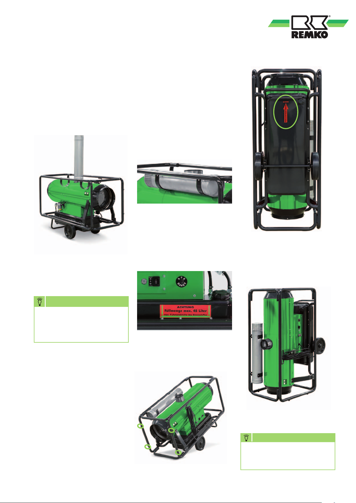
The units can be transport in their
normal operating position or in a
vertical position to save space.
Proceed as follows for a vertical
position:
1. Secure the exhaust gas duct
in its designated position with
the belts.
2. Check the level of the fuel tank.
The maximum capacity of 45
litres must not be exceeded (see
sticker on side).
4. In this position, the unit can only
be secured to the surrounding
tubular frame for transport using
suitable attachment material.
NOTE
There must be no counter pressure
arising from incorrect installation
of the exhaust gas routing under
any circumstances.
Notes for implementing the 1st.
BImSchV
Units that are not expected to
be operated for longer than
3 months in the same location
are not subject to any approvals
or monitoring as per the 1st.
BImSchV.
3. Tip the unit towards the outlet
side and align on the 4 rubber
buffers.
NOTE
The unit may only be loaded
when cooled.
7
Page 8
REMKO ATK
Commissioning
The units must be checked
for visible defects on the
operating and safety devices as
well as proper installation and
correct electrical wiring before
commissioning.
One person, who has been
adequately trained in the handling
of the units, must be tasked with
operation and monitoring of the
units.
ATTENTION
In the event of defects that
endanger the operational
safety of the units, operation
of the units must be
discontinued immediately and
the supervisor informed!
Paraffin formation with low
outside temperatures.
Even at low temperatures, an
adequate supply of flowing
heating oil must be ensured.
■
The in-built fuel pre-heating
[] is activated only when
the power plug is connected
to a functional mains socket
and the ambient temperature is
lower than 10°C
■
It is not possible to rectify
paraffin separation that
has already occurred with
the heating. If paraffin has
already formed it is necessary
to clean out the complete fuel
system
Connecting the units to
the electrical power supply
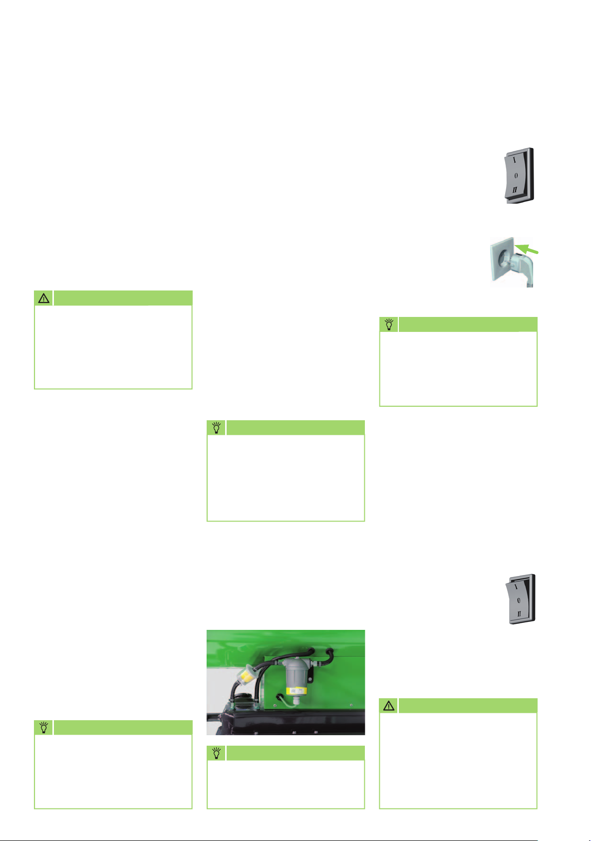
1. Move the operating
switch to the "0"
(Off) position.
2. Connect the power plug to a
properly installed
and appropriately
safeguarded
230 V/50 Hz
mains socket.
NOTE
The electrical connection for
the units must be made at a
separate feed point with a residual
current device in accordance with
VDE 0100, Section 55.
■
The units must installed to be
stable in a horizontal position
■
Ensure there is an adequate
supply of combustion air
■
Check that the inlet and outlet
are free
■
Prevent overpressure and
underpressure in the installation
area
■
The fuel supply must be
ensured with suitable fuel
■
The fuel tank may only be filled
when the unit is switched off.
Do not use biodiesel!
■
Use only clean and suitable
tanks for filling
NOTE
Paraffin formation can start
at temperatures below 5°C.
To avoid this appropriate
preventative measures must
be implemented, e.g. winter
Diesel.
Fuel filter
The fuel filter [] must be checked
for dirt or paraffin formation
before the unit is started.
Ventilation only operation
In this switch position, the supply
air fan runs permanently.
The units can be used for air
recirculation or ventilation
purposes.
1. Check the content of the fuel
tank.
2. Move the operating
switch to the "II"
(Ventilate) position.
Thermostatic regulation and
heating operation are not possible
in this operating mode.
ATTENTION
NOTE
The exhaust gas values must
be checked and/or adjusted
by authorised and qualified
technicians according to
the local conditions.
8
NOTE
Only suitable and clean fuels
may be used.
In this operating mode,
the fuel tank must always be
filled with a basic quantity of
heating oil.
There is no warranty claim
for pump damage due to dry
running!
Page 9
Care and maintenance
Heating with room thermostat
The units operate fully
automatically and according
to the room temperature.
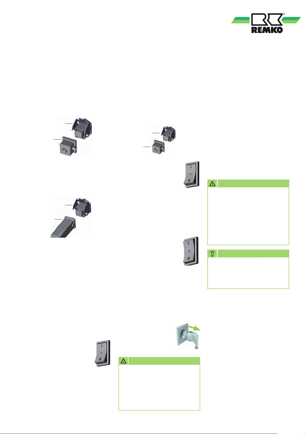
1. Pull out the strapping plug [2].
1
2
2. Connect the room thermostat
plug [3] to the thermostat
socket [1] on the unit.
1
3
3. Place the room thermostat at a
suitable location in the room.
The thermostat sensor must
not be located directly in the
warm air flow and must not
be placed directly on the cold
floor.
4. Set the desired room
temperature on the room
thermostat.
5. Move the operating switch to
the "I" (Heating) position.
The unit starts
automatically after a brief
burner pre-ventilation if
heat is required and then runs fully
automatically.
Heating without room
thermostat
The units operate
in permanent operating mode.
1. Connect the supplied strapping
plug [2] to the thermostat
socket [1] on the unit.
1
2
2. Move the operating
switch to the "I"
(Heating) position.
Shutdown
1. Move the operating
switch to the "0"
(Off) position.
The supply air fan runs to cool
the combustion chamber and
switches off independently.
The fan can switch on and run
several times before the final
shutdown!
2. With longer periods
of inactivity,
disconnect the units
from the mains
power supply.
ATTENTION
Never interrupt the power
supply prior to the completion
of the follow-up cooling phase.
There is no warranty claim
for damage to the units from
overheating.
Regular care and observation
of some basic requirements will
ensure trouble-free operation and
a long service life of the units.
The units, including combustion
chamber and burner, must be
cleared of soot deposits, dust and
dirt after every heating period
or according to the operating
conditions.
The oil filters must be cleaned and/
or replaced at least once annually
or more frequently according to
the contamination of the fuel.
ATTENTION
Before undertaking any work
on the units, the power
plug must be removed from
the mains socket. There is
an acute risk of injury from
automatic fan switch-on,
especially when the unit
enclosure is opened.
NOTE
Adjustment and maintenance
work may only be carried out
by authorised and qualified
technicians.
■
Keep the units free of dust and
other debris
■
Only clean the units with a dry
or moistened cloth
■
Never subject to direct jets of
water.
such as a high-pressure cleaner
etc.
■
Never use abrasive or solvent-
based cleaners
■
Use only suitable cleaners, even
for heavy contamination
s
s
s
9
Page 10
REMKO ATK
s
s
s
■
Use only clean EL heating oil or
diesel fuel. Beware of paraffin
formation!
■
Keep the burner head clean
■
Wear parts such as the oil
nozzle and seals must be
checked regularly and replaced
if necessary. The oil nozzle
must be replaced before the
start of each heating season!
Proceed as follows to clean the fuel
tank:
E
D
Maintaining the burner
Clean the burner components as
described:
4
2
3
1
5
6
7
■
Depending on its condition,
the fuel filter must be replaced
before each heating season.
Note the direction of flow!
■
Check that the safety devices
are operating correctly at
regular intervals
■
In the event of diminishing heat
capacity, smoke formation and/
or poor ignition, perform a unit
and burner inspection
Cleaning the fuel tank
The fuel tank must be cleaned:
■
After each heating period
or earlier according to
the operating conditions
■
Before and after extended
periods out of operation
■
In the event of frequent
contamination of the fuel filter
■
In the event of condensate
formation in the fuel
■
Following paraffin precipitation
in the fuel tank
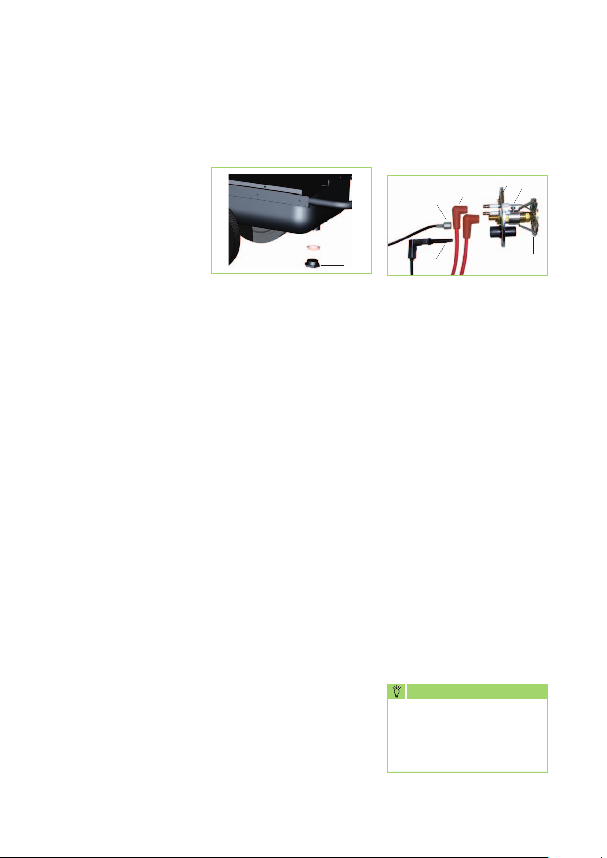
1. Unscrew the drain screw [D] and
drain the remaining (old) fuel
into a suitable container.
2. Rinse the fuel tank thoroughly
with clean heating oil or other
suitable agent (several times if
necessary).
Do not use water for rinsing!
3. Do not use solvent-based
cleaners.
This can damage the internal
coating of the fuel tank!
4. Avoid the use of pressure
washers.
5. After cleaning, replace the drain
screw [D].
The sealing ring [E] must be
replaced on each occasion!
6. The fuel tank must be filled
with clean heating oil or diesel
fuel.
Do not use biodiesel!
7. Start the unit and run for
approx. 5 min.
1. Remove the photocell [1] from
its mounting [5].
2. Disconnect the ignition cable [2].
3. Remove the union nut [3] of the
oil pressure line from the nozzle
mounting.
Beware of dripping fuel!
4. Remove the locking screw from
the mounting plate [4] and, by
turning the plate [4] slightly
in an anti-clockwise direction,
remove the burner from
the burner pipe.
5. Clean the ignition electrodes
[6], baffle plate [7] and photocell
mounting [5].
6. Position the ignition electrodes
[6] in accordance with reference
values.
7. Following maintenance work,
refit all parts carefully in reverse
order.
NOTE
When positioning the baffle
plate [7], always ensure
that the aperture [5] is
not obscured by a strut on
the plate.
10
Page 11
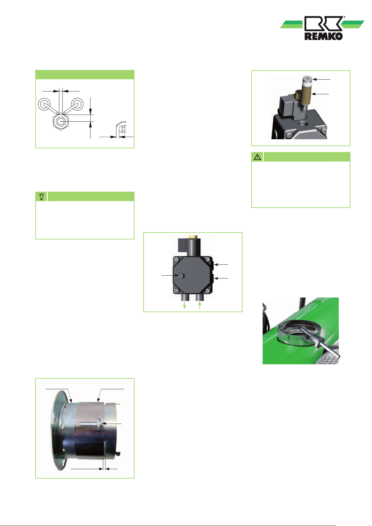
Setting the ignition electrodes
2 - 3
7
7
All sizes are approximate values and are in mm.
The optimum setting must be
adapted to the unit-specific
conditions.
NOTE
Use only suitable tools to
remove the oil nozzle and
use the nozzle mounting for
resistance!
Setting the air slide
The air slide is factory set.
The combustion air may only be
adjusted to the unit-specific or
local conditions by an authorised
and qualified technician.
Setting the pump pressure
The pump pressure may only
be set and/or modified when
a suitable oil pressure gauge is
connected to the connection [P].
The pump pressure is modified by
turning the pressure adjustment
screw [A]:
Clockwise:
Increase pressure
Anti-clockwise:
Decrease pressure
The pump pressure is determined
according to the heating capacity
of the unit and the size of
the nozzle.
P
A
Return flow Inlet
U
C
B
ATTENTION
Never let the pump run for
extended periods without any
fuel. Never leave the units for
extended periods with a pump
that has run dry.
Exhaust gas analysis
To perform the exhaust gas
analysis, the exhaust gas
measuring instrument probe must
be placed in the centre of the heat
exchanger pipe port.
Fig. Exhaust gas connection
After loosening the clamping
screw [K], the air slide is fine
adjusted by means of exhaust gas
measurement.
Burner head
approx. 4 - 5 mm
Air slide
K
CO2 value: approx. 11 - 12%;
Soot level: 0 - 1 in acc. with
Bacharach
Cleaning the cartridge filter
Clean the cartridge filter [B] of
the fuel pump at regular intervals
and/or replace as necessary.
1. Turn the stopper [C] upwards
out of the pump using a
hexagon wrench.
2. Carefully remove the cartridge
filter [B] from the stopper.
3. Clean and/or replace
the cartridge filter [B].
4. Push the filter back onto
the stopper and screw both
back into the pump.
The measurement may also be
performed in an exhaust gas
duct. For this, a corresponding
measurement aperture must be
created in the duct at a distance of
approx. 300 mm behind the unit
port.
Notes for implementing the 1st.
BImSchV
Units that are not expected to
be operated for longer than 3
months in the same location
are not subject to any approvals
or monitoring as per the 1st.
BImSchV.
11
Page 12
REMKO ATK
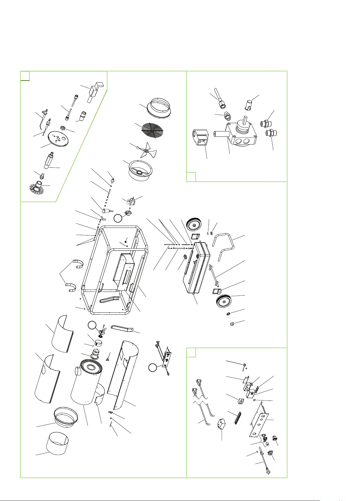
Exploded view of the unit
B
63
64
57
61
97
31
64
103
104
105
57
62
32
56
34
60
123
58
119
118
126127
35
59
52
53
54
116
117
15 22
98
39
111
101
102
104
A
11
30
99
126
18
117
127
95
121
92
96
125
124
2920
2724
2819
1
100
A
41
42
B
69
70
90
70
75
82
7674
83
23
40
122
112
We reserve the right to modify the dimensions and design as part of the ongoing technical development process.
12
50
113
90
114
85
77
81
79
88
89
84
71
73
80
Page 13
Spare parts list
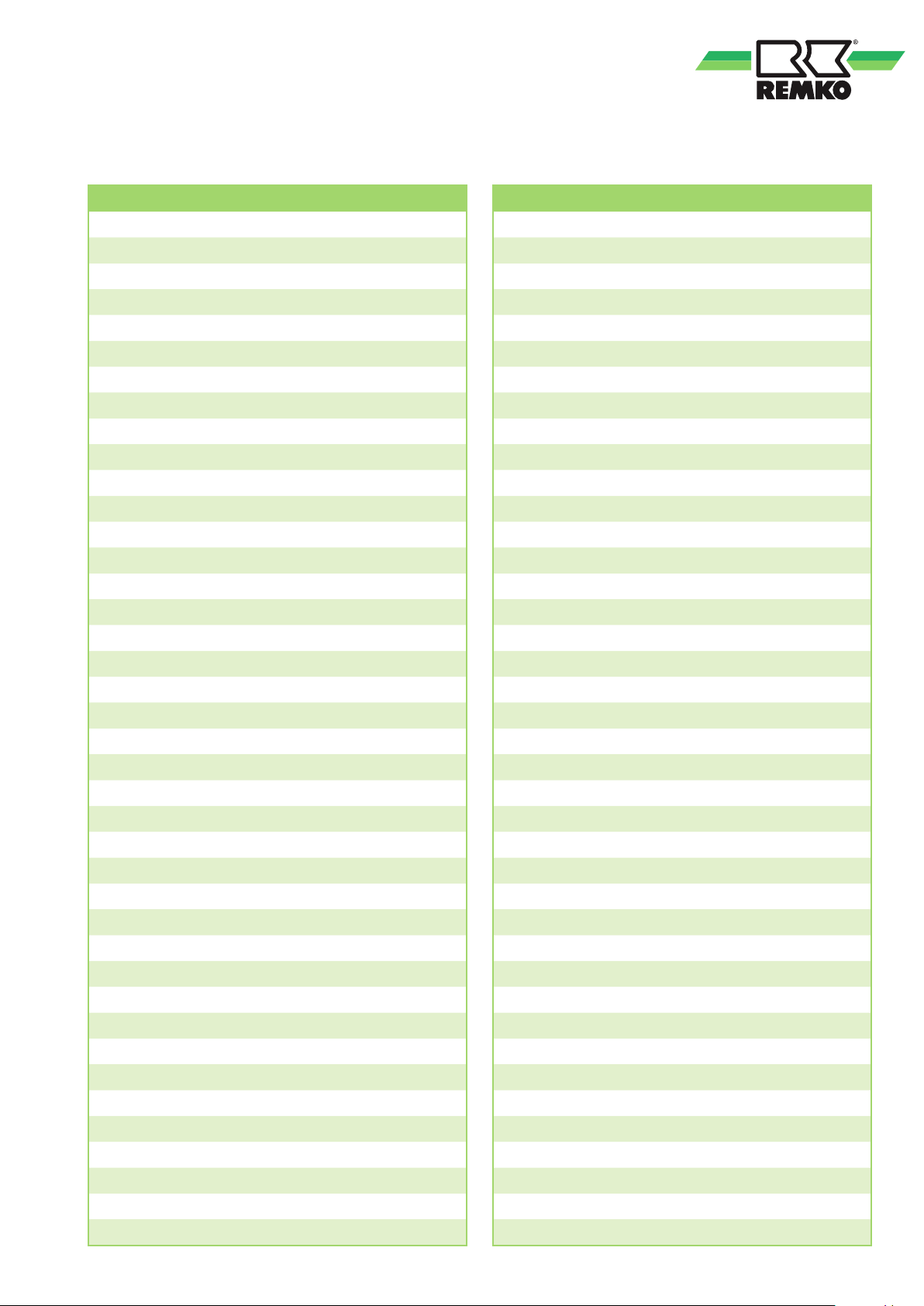
No. Designation EDP no. No. Designation EDP no.
Fuel tank 1103965
01
Carrier housing 1103966
11
OV mounting 1103967
15
Steel tubular frame 1103968
18
Locking ring 1101622
19
Hubcap 1101623
20
Oil pre-heater 1103969
22
Housing lower section 1103970
23
Axle support bracket 1103971
24
Axle 1103972
27
Wheel 1101621
28
Stand 1103973
29
Stabiliser 1103974
30
Intake connection port 1103975
31
Cover 1103976
32
Inspection cover 1103977
34
Rubber buffer 1103978
35
Fan housing 1103980
39
STB support bracket 1103981
40
Cable gland 1103982
41
Counter nut 1103983
42
Combustion chamber compl. 1103984
50
Burner pipe 1103985
52
Safety connector 1111680
53
Air slide 1103729
54
Mounting plate 1103731
56
Ignition electrode 1103986
57
Nozzle mounting 1103987
58
Nut M14 1107134
59
Baffle plate 1103730
60
Photocell mounting 1111676
61
Oil nozzle (1.0/80° W) 1103988
62
Photocell 1108209
63
Oil pressure line (flex) 1111673
64
Aftercooler thermostat 1107182
69
Electrical assembly compl. 1109953
70
PG plate 1102533 Thermostat plug 1101020
76
Ignition transformer 1107143 Cartridge filter for oil pump 1102088
77
Thermostat socket 1101018 Connection cable for MV 1102825
79
Strapping plug 1101019 Fastening strap for exhaust gas duct 1000960
80
Terminal strip 1103781
81
Mounting 1103782
82
Auxiliary relay 1107375
83
O-ring 1103783
84
Ignition cable 1107137
85
6 A fuse 1103785
88
Mains cable with IP 67 plug 1109942
89
Safety temperature limiter 1103711
90
Tank cap with valve 1102166
92
Oil intake pipe 1103990
95
Bolted connection ¼" M12 x 1.75 1103991
96
Air-inlet grille 1103992
97
Fan blade 1103993
98
Fan motor compl. 1103994
99
Condenser 1103995
100
Solenoid 1103766
101
Fuel pump compl. 1109946
102
Pump coupling 1102936
103
Connection nipple 1/4" 1111674
104
Connection nipple 1/8" 1111672
105
Fuel filter (one-way) 1102146
111
Hose connection port 350 Ø 1103997
112
Insulation 1103998
113
STB fastening clip 1103999
114
Hose clip 1103762
116
Oil hose flex. 1104000
117
Oil hose flex. 1104001
118
Connection nipple 1/4" 1111674
119
Oil hose flex. 1104002
121
Outlet nozzle 1103989
122
Mounting bracket for exhaust gas duct
123
Oil drain screw 1103778
124
Sealing ring 1103777
125
Hose clip 1107141
126
Bolted connection
127
Without figure:
1104003
1102146-4
When ordering spare parts, please state the EDP no., unit number and type (see name plate)!
13
Page 14

REMKO ATK
Troubleshooting
Malfunctions Cause:
The supply air fan does not start. 2 – 3 – 4 – 6 – 7 – 8 – 25
The supply air fan runs but the burner does not ignite.
The unit malfunctions without generating a flame.
The unit switches off during operation.
(The fault lamp in the automatic burner lights up)
Smoke formation during operation. 7 – 10 – 11 – 13 – 15 – 17 – 19 – 21 – 22 – 24
The unit does not switch off in operating switch position "0". 18 – 25
ATTENTION
Repair work on the electrical installation and on the burner must be performed exclusively by authorised
specialists for safety reasons.
1 – 5 – 6 – 9 – 10 – 11 – 12 – 13 – 14 – 15 – 16 – 17
20 – 21 – 23 – 24 – 26
4 – 5 – 6 – 7 – 8 – 9 – 10 – 11 – 13 – 15 – 16 – 17
19 – 20 – 21 – 22 – 23 – 24 – 26
Cause: Remedial measures:
1. Air in fuel system during start-up.
2. The unit is not connected to the electricity supply. Check the power plug, mains socket and mains voltage.
3. No plug in the thermostat socket. Connect the thermostat/strapping plug to the thermostat socket.
4. The room thermostat is set too low.
5. The fault lamp in the automatic burner lights up. Reset the automatic burner by pressing the malfunction button.
6. Malfunction in the automatic burner. Replace the automatic burner.
7. The motor is overloaded.
(The fan runs irregularly or is blocked)
8. The fuel pump is blocked. Check the fuel pump and replace if necessary.
9. The fuel tank is empty. Fill the fuel tank with clean EL heating oil or diesel.
10. The fuel filter is contaminated. Replace the fuel filter.
11. The nozzle is blocked or of the wrong size. Replace the nozzle (ensure correct type and size)!
12. The electrodes are incorrectly set, the insulation has cracked. Adjust and replace if necessary.
13. The air slide of the burner head has moved or is contaminated.
14. The solenoid valve does not open.
15. The pump pressure is improperly set. Replace the pump coupling.
16. The pump coupling is faulty.
17. Leak in the intake line or fuel filter. Check and replace faulty parts if necessary.
18. The solenoid valve does not close.
19. The protection grid on the supply air fan is contaminated.
20. Shutdown by safety temperature limiter (STB).
21. Air bubbles in fuel system.
22. Insufficient ventilation. Open door or window.
23. The photocell is contaminated or faulty. Clean the photocell and replace if necessary.
24. Improper exhaust gas routing. See chapter "Exhaust gas routing".
25. Operating switch malfunction. Check the operating switch and replace if necessary.
26. Paraffin precipitation in the heating oil.
Press the fault key of the automatic burner.
Repeat if necessary (max. 3 times).
Set the room thermostat higher than room temperature.
Allow the motor to cool.
Check the smooth running of the fuel pump.
Check the electrical and mechanical functioning of the motor.
Adjust using CO2 indicator and soot pump.
(CO2: 11 - 12%, soot level in acc. with Bacharach: 0 - 1).
Check the solenoid valve and replace if necessary.
The STB has triggered or is faulty.
Replace the pump coupling.
Disconnect the fuel line at the main filter, the flame extinguishes.
Clean the protection grid.
Check the intake protection grid and clean if necessary.
Reset the STB and automatic burner.
Start the unit to discharge the air through the nozzle.
Repeat this procedure up to 3 times if necessary.
Clean the entire burner system.
See also chapter "Commissioning".
14
Page 15
Technical data
ZT
ZE
M
~
STB
MV FZ
NK
1 2
3
4
5 6
7
8 9 10
11 12
RT
S
2
3
1
A
2
A
3
A
4
B
5
B
6
B
KL
C
Ausf. ACD AIR50B_13
A1
A2
14
11
HS
HZ
RS
F
Series ATK 50-S
Nominal heat load max. kW 48
Nominal heat capacity kW 43.5
Air volume m3/h 2400
Temperature increase ∆
t
Fuel Heating oil EL in accordance with DIN 51603-1 or diesel fuel
Max. fuel consumption l/h 4.8
Nozzle (DELAVAN) 80° W USG 1.0
Pump pressure, approx. bar 11
Tank capacity ltr. 45
Power supply 1~ V/Hz 230/50
Elec. current consumption max.
Elec. power consumption max.
1)
1)
Electrical protection (provided by the customer)
Sound pressure level LpA 1m
2)
Exhaust connection Ø mm 150
Dimensions: Length mm 1535
Width mm 650
Height mm 1005
Weight kg 102
1)
Unit incl. tank heater
2)
Noise measurement in acc. with DIN 43635 - 01 KL 3
K 70
A 4.0
kW 0.85
A 10
dB(A) 74
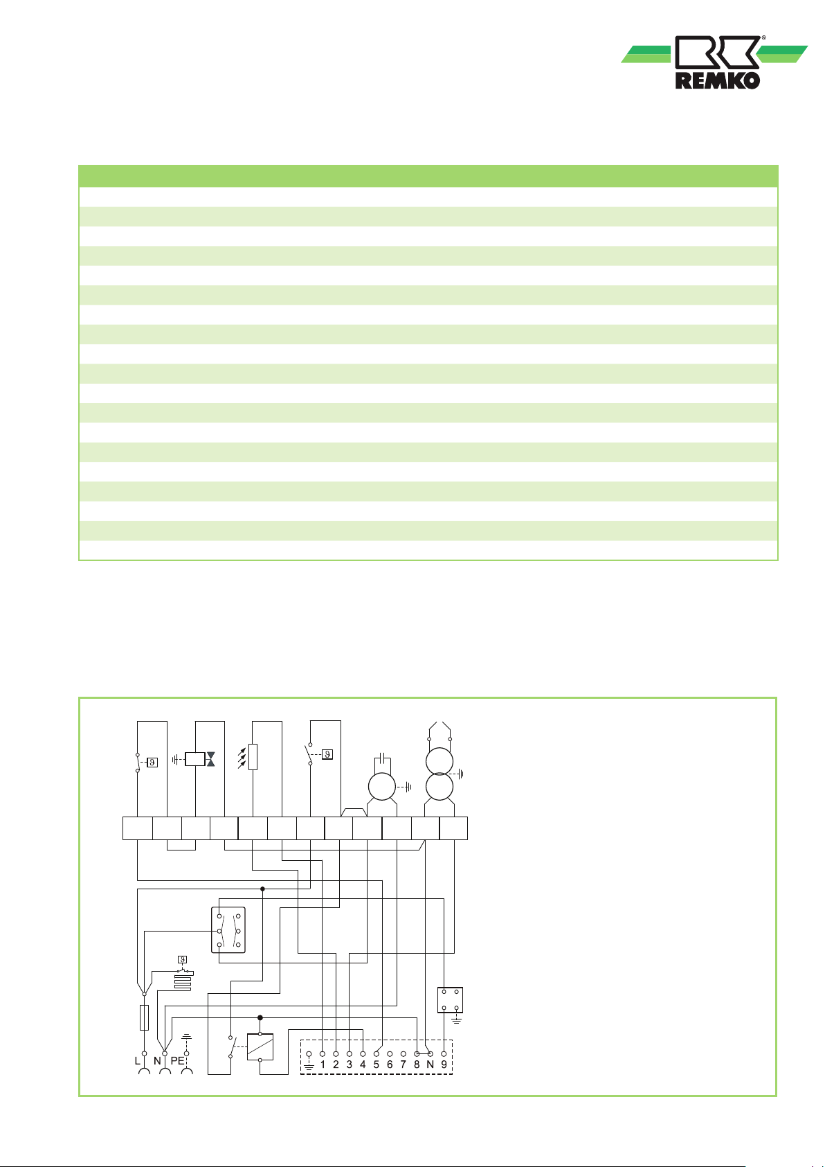
Electrical wiring diagram
We reserve the right to modify the dimensions and design as part of the ongoing technical development process.
Legend:
C = Start-up capacitor
F = Fuse 6.3 A - T
FZ = Photocell
HS = Auxiliary relay
HZ = Fuel pre-heater
M = Motor
MV = Solenoid valve
NK = Aftercooler thermostat
RS = Relay socket
RT = Thermostat socket
S = Operating switch (I O II)
STB = Safety temperature limiter
ZE = Ignition electrode
ZT = Ignition transformer
15
Page 16
REMKO INTERNATIONAL
... and also right in your neighbourhood!
Take advantage of our experience and advice
REMKO GmbH & Co. KG
Klima- und Wärmetechnik
Im Seelenkamp 12 D-32791 Lage
Postfach 1827 D-32777 Lage
Telephone +49 5232 606-0
Fax +49 5232 606-260
E-mail [email protected]
Internet www.remko.de
Consulting
Thanks to intensive training,
our consultants are always
completely up-to-date when it
comes to technical expertise.
This has given us the reputation
of being more than just an
excellent, reliable supplier:
REMKO, a partner who helps to
solve problems.
Sales
REMKO offers not just a well-
established sales network both
nationally and internationally, but
also has exceptionally highly-
qualified sales specialists.
REMKO employees in the field
are more than mere salespeople:
above all, they must be
advisers to our customers in
air conditioning and heating
technology.
Customer service
Our units operate precisely and
reliably. However, in the event of
a malfunction REMKO customer
service is quickly on the scene.
Our extensive network of
experienced dealers guarantees
quick and reliable service.
We reserve the right to make technical changes and provide no warranty as to the accuracy of this data!
 Loading...