

Page 1
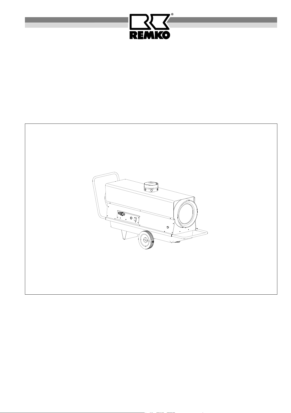
REMKO AT 25
Automatic oil heater
Operation
Technology
Spare Parts
Edition GB – M04
REMKO - powerful like a bear.
Page 2

Page 3
Operating Instructions
Make sure to read these instructions carefully before starting/using the unit!
Our guarantee will become void when the unit supplied by us is used and
installed for inadequate purposes, or maintained incorrectly, etc.,
or if it is changed without our prior consent.
Subject to alterations!
Automatic oil heater
REMKO AT 25
Contents Page
Safety Instructions 4
Description of device 4
Provision of air heaters 5
Installation instructions 6
Exhaust system 6
Starting 7
Unit shut down 7
Maintenance and service 8
Burner adjustment 8
Always keep these operating instructions near or on the unit!
G
Contents Page
Exhaust measurement 9
Service and Guarantee 9
Fuel pump 10
Technical data 10
Wiring diagram 10
Troubleshooting 11
Exploded view 12
Spare part list 13
Maintenance log 14
G
3
Page 4

Safety Instructions
Please make sure that the relevant local building
and fire protection codes as well as the regulations
of the employer's liability insurance associations
are observed when the units are used.
◊ The units may be operated only by persons who
have been trained in this field.
◊ The unit is to be installed and operated in such a
way as to ensure that the employees are not endangered by waste gases and radiation heat and that no
fire can break out.
◊ The unit may only be installed and operated in
rooms, when the air-rate fed to the unit is sufficient
for combustion.
◊ Without an exhaust system, the unit may only be op-
erated in well aerated rooms. The permanent stay of
persons in the room where the units are installed is
prohibited.
Appropriate prohibition signs are to be fitted at the
entrances.
◊ Mobile fuel reservoirs may be installed only when the
technical rules for combustible liquids are observed.
Description of Device
The unit is fired directly with heating oil EL or diesel and
can be operated with or without an exhaust-gas connection. It is intended for mobile and fully automatic deployment.
A fuel container is built under the unit and it is equipped
with automatic tank heating, a high-pressure atomizing
oil burner with optical flame monitoring, a low maintenance axial ventilator, a connection cable with plug, a
room thermostat socket and a fivefold filter system.
The unit complies with the basic safety and health requirements of the relevant EU stipulations and is reliable and simple to operate.
The unit can be used e.g. in the following areas:
- for drying new buildings;
- for point heating of outdoor workplaces;
- for point heating of workplaces in open, non firehazard fabrication rooms and halls;
- for temporary heating of closed and open areas;
- for de-icing of machines, vehicles and non flammable
storage goods;
- for tempering frost-endangered parts.
◊ The unit is to be installed only on a non-combustible
ground.
◊ The unit may not be installed and operated in inflam-
mable and explosive surroundings.
◊ A safety zone of 1.5 m around the unit, as well as a
minimum distance of 3 m from the unit's blower aperture is to be maintained, even in the case of non
combustible objects.
◊ The blower aperture of the unit may not be narrowed
or equipped with hoses and conduits.
◊ The protective air suction grille is always to be kept
free from dirt and loose objects.
◊ Make sure not to introduce foreign matters into the
unit.
◊ Make sure not to expose the unit to direct water jets.
◊ All electric cables outside the unit are to be protected
from damage (e.g. caused by animals, etc.).
◊ Make sure always to pull the mains plug out of the
mains socket when maintenance and repairs are
carried out.
During the unit’s operation, safety devices may
neither be bridged nor blocked!
G
On account of the construction type, a fixedlocation device installation is not permissible!
G
Working of Device
The automatic tank heating is activated by connecting
the mains plug with a mains socket.
When the unit has been switched on or when heat is re-
quired (automatic function with room thermostat) the
supply air fan starts. The fan blows air into and along
the combustion chamber.
When the preliminary ventilation is over, the electromagnetic valve opens and supplies fuel to the nozzle.
The fuel, sprayed under high pressure, is enriched by
an adequate quantity of oxygen according to the heating
capacity and ignited by an electric spark.
Ignition is automatically terminated as soon as a perfect
flame burns and the flames are controlled by the automatic burner relay. After a few seconds hot air is blown
out.
In case of any troubles, or if the flame is unstable or
tends to go out, the unit is switched off by the automatic
burner relay. The fault indicator warning lamp of the
automatic burner relay lights up. A restart cannot be
made before the manual release of the automatic
burner relay.
When the unit has been switched off via the operating
switch or the room thermostat, the supply air fan continues running for some time to cool down the combustion
chamber and then it stops automatically.
Depending on the required heat rate the function described above is repeated automatically in the case of
an operation with thermostat.
For optimum unit operation, the device should not
be operated at an ambient temperature above 25 °C.
G
4
Page 5
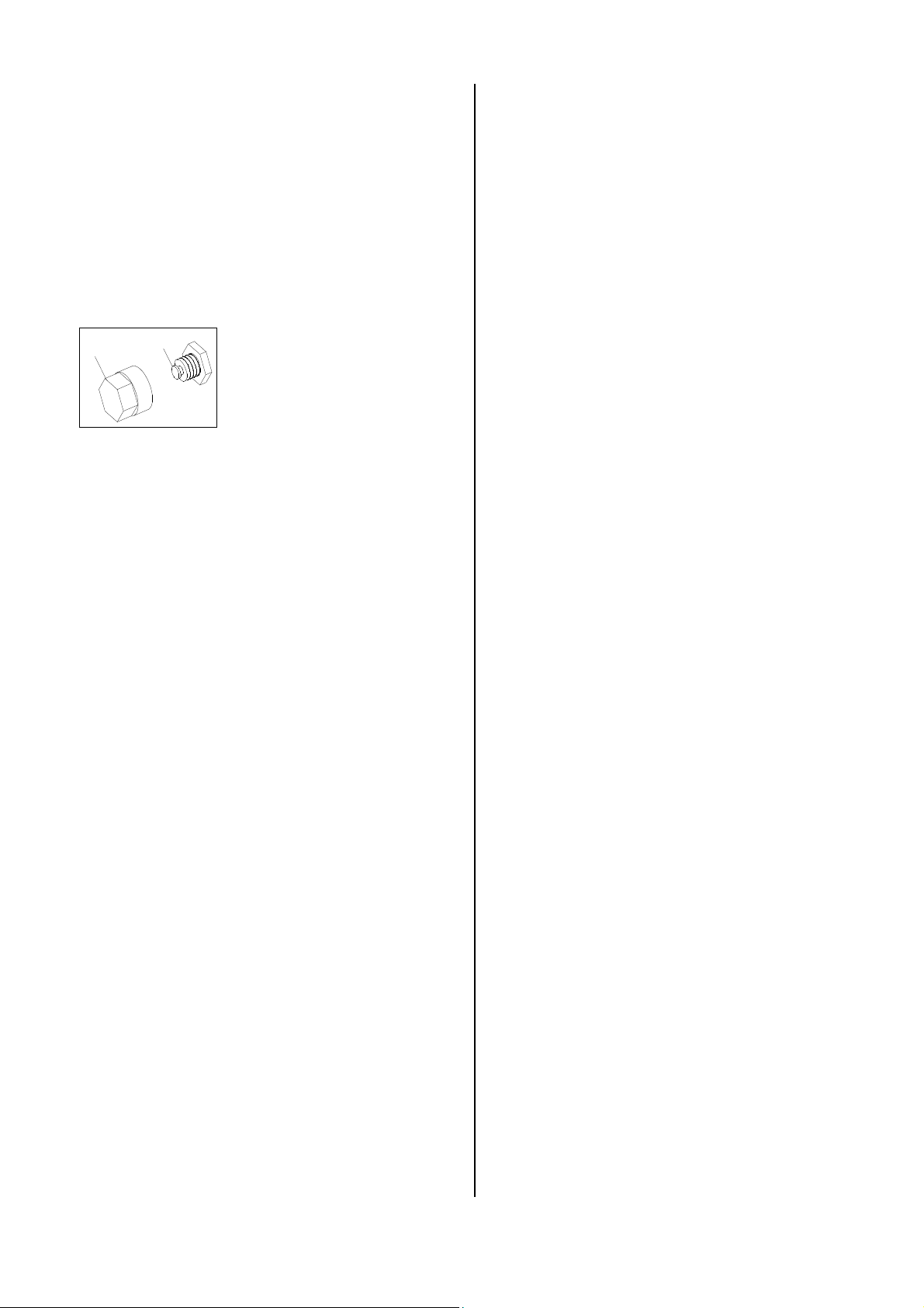
Safety temperature limiter (STB)
The safety temperature limiter (STB) interrupts the
burner operation in the event of overheating and locks
all unit functions.
If the safety temperature limiter has triggered, the cause
of the disturbance must first be localised and eliminated. Resetting via the "RESET" key is only possible
after the sensor has cooled to below ca. 90 °C.
The safety temperature limiter is unlocked by pressing
the reset key.
1
2
1. Detach the protection cap 1.
2. Press the reset key 2.
3. Replace the protection cap.
Provision for Air Heaters
For the deployment of the unit, the relevant guidelines
must be observed
1. Operating personnel
1.1 The unit must only be operated by persons who
have been trained in its operation.
2. Installation
2.1 The unit must be installed so that it can stand in a
stable position.
2.2 The unit must be installed and operated in such a
way that the employees are not exposed to the
danger of exhaust gases and radiant heat and that
the occurrence of fires is ruled out.
2.3 The unit may only be installed and operated in
rooms if a quantity of air sufficient for the combustion is supplied to the unit and the exhaust gases
are removed to the exterior.
A natural air supply sufficient for the combustion is
present if e.g.
The room contents in m² correspond with at least
10 times the nominal heat load in kW of all the
units operating in the room and if windows and
doors ensure a natural change of air.
2.4 In deviation from point 2.3, the unit can be operated without an exhaust system in rooms if these
rooms have a sufficient air supply and are well ventilated and if materials harmful to health do not
reach an unhealthy concentration.
2.5 A good natural air supply and ventilation is the case
if e. g.
The room contents in m² correspond with at least
30 times the nominal heat output of all units operating in the room and a natural change of air is ensured through windows and doors, or
openings which are not lockable are present in the
region of ceiling and floor for the air supply and for
out going air and the size of these openings in m²
corresponds with at least 0.003 times the nominal
heat output in kW of all units operating in the room.
2.6 The unit must not be installed or operated in rooms
and areas where the danger of fire or explosion exists.
3. Room drying
3.1 In deviation from point 2.3, in order to dry rooms
with an air supply sufficient for the combustion,
heating units can be operated without the exhaust
gases being removed to the exterior. In these
rooms, the permanent presence of persons is forbidden. Signs on the entrances to the rooms must
indicate that this is forbidden.
4. Examination
4.1 The unit must be tested by an expert as to its work
safety specific condition in accordance with the required deployment conditions but at least once annually.
4.2 The exhaust values of the burner must be checked.
5. Monitoring
5.1 When starting work, the persons commissioned
with the operation of the unit must check the unit
for obvious defects or deficiencies on the operational and safety mechanisms and check that the
safety mechanisms are present.
5.2 If defects or deficiencies are discovered, the supervisor must be informed.
5.3 In the case of defects or deficiencies which en danger the operational safety of the unit, its operation
must be terminated.
6. Installation in closed, well aerated rooms without connection to a chimney
6.1 The operation of the units is admissible when the
minimum air quantity needed for combustion and
mentioned in point 2.5 is supplied.
6.2 A safe exhaustion of the waste gases is to be ensured to exclude inadmissible pollution.
Fresh air is fed from below;
waste gases are exhausted towards the top.
7. Correct usage
7.1 The unit are to be used only for heating purpose in
industrial or commercial application because of their
construction and equipment.
7.2 If specification of the manufacturer or legal regulations, are not followed or if unauthorised changes
are made on the unit, the manufacturer is not liable
for resulting damages.
5
Page 6
Installation Instructions
The units are generally to be operated in accordance
with the safety rules, the building code of the land concerned and the fire protection code.
◊ Avoid under or overpressure in the room where the
unit is installed, as this would result in combustion
troubles.
◊ Suction and blow-out cross sections may not be re-
duced
Exhaust system
In the outdoors or in open rooms, the operation of the
device is also possible without an exhaust system.
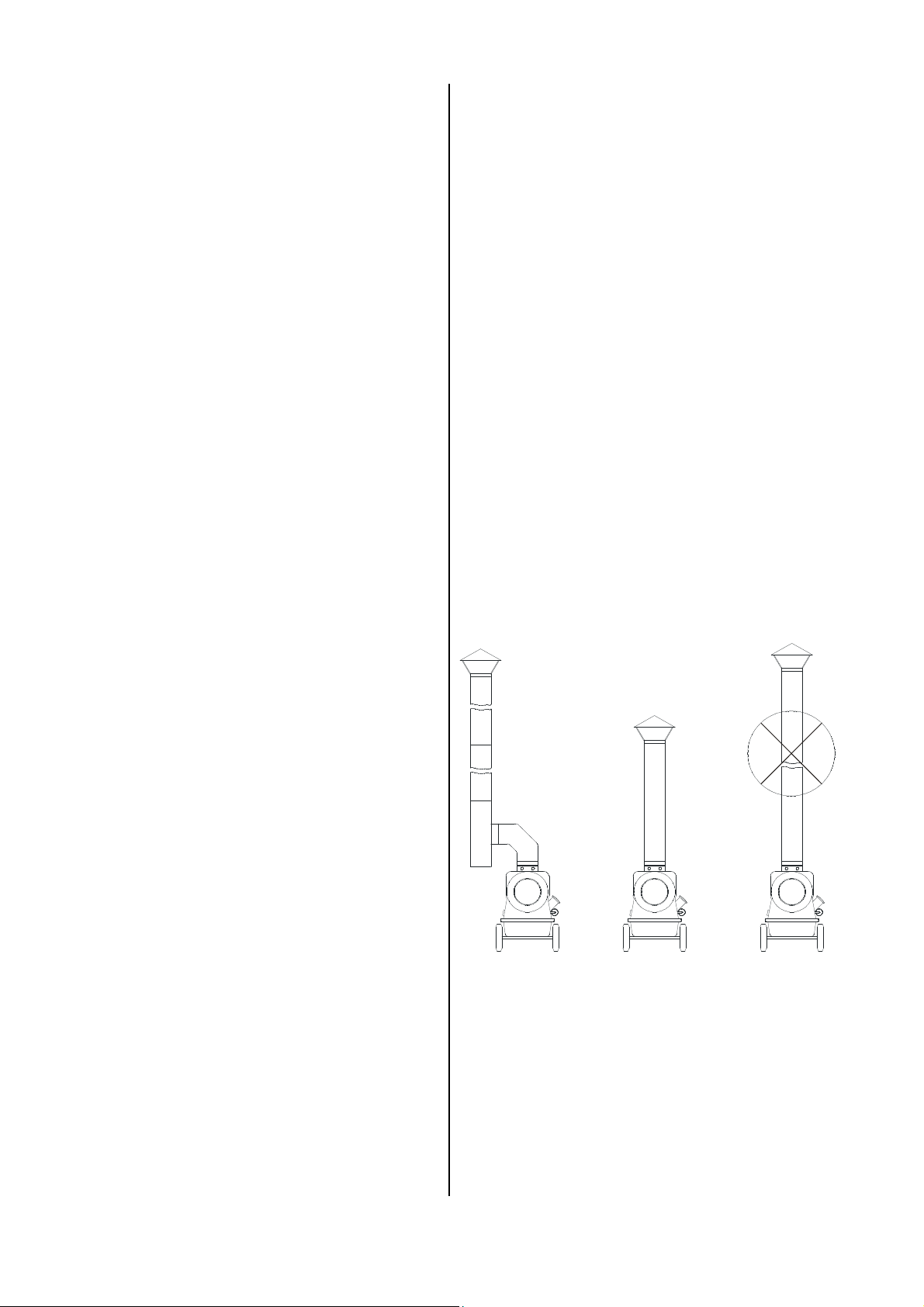
However, we recommend a 1 m exhaust-pipe (see example 2) with a rain hood placed on top so as to rule out
the penetration by rainwater and dirt.
If the device is used for temporary room heating, the
combustion gases may have to be removed to the exterior. The exhaust-pipe parts must be laid in such a way
that a minimum suction of 0.1 mbar is guaranteed.
◊ It is prohibited to connect conduits or hoses to the
unit blow-out opening.
◊ Make sure that the technical regulations for combus-
tible liquids are observed when mobile fuel holders
are installed.
Outside Installation
◊ The units are to be installed outside and to be pro-
tected from atmospheric effects to avoid damage.
◊ Make sure that no danger or inadmissible annoy-
ance is caused by the operation of the unit.
Room Heating
◊ For room heating, hot air generators may only be op-
erated with a room thermostat (accessories).
◊ Make sure that sufficient fresh air is fed to ensure
perfect combustion. Fresh air is to be fed preferably
through windows and doors or through sufficiently dimensioned openings in the outer wall.
Safety Distances
◊ Make sure to observe the following safety distances
to ensure a safe operation of the unit:
– towards the top, fire-retarding ceiling 1,5 m
– towards the sides, non-burning objects 0,6 m
– blow-off side, with non-burning objects 3,0 m
– suction side, for perfect air supply 1,0 m
◊ The floor and the ceiling must be from fire-retarding
materials.
It must be made sure in all cases that counter
pressure due to an incorrect exhaust system is
G
ruled out.
Malfunction-free operation is guaranteed if the exhaust
system is installed in an ascending direction and with
vertical end pipes.
The exhaust system must terminate at least above the
height of the eaves but better still above roof height in
order to avoid counter pressure caused by weatherrelated circumstances (e.g. wind).
All exhaust-pipe parts must be attached reliably. Their
diameter must not be smaller than that of the exhaust
nozzle of the device (∅ 150 mm).
The minimum distance of 0.6 m to combustible parts
must not be exceeded.
Exhaust-pipe parts including attachment material are
available as accessories.
Electric Connection
◊ The unit are operated with 230 V alternating current.
◊ Electric connection is carried out via a fitted mains
cable with shockproof plug.
◊ Possibly required extension cables must be selected
according to the existing cable length, the unit’s con-
necting line and the intended purpose.
All extension cables are to be used only after
having been removed from the roller.
G
The electric connection of the unit is to be carried
out via a special supply point with fault current
G
safety switch.
6
Example 1 Example 2 Example 3
operating with
extended
waste gas pipe
condensate trap
necessarily
Important hint.
Make sure that the waste gas pipes are correctly installed with a condensate trap (see example 1), to avoid
damage to the combustion chamber through humidity
deposits (condensate) (see example 3).
The lateral openings in the exhaust connection must not
be closed or covered.
operating without
extended
waste gas pipe
max. 1m
Inadmissible
arrangement.
Page 7
Starting
Prior to starting, the unit is to be checked to make sure
that there are no visible defects on the control and
safety devices, that the unit has been installed correctly
and that it has been properly connected to the mains.
A properly trained person is to be charged with the operation and control of the unit.
◊ Install unit in a stable position.
◊ Make sure that combustion air is supplied.
◊ Make sure that the air can be sucked in and be ex-
hausted freely.
◊ Avoid overpressure and underpressure in the room
where the unit has been installed.
◊ Make sure that enough fuel is supplied.
◊ Fill fuel tank with clean fuel oil EL or diesel with the
unit switched off.
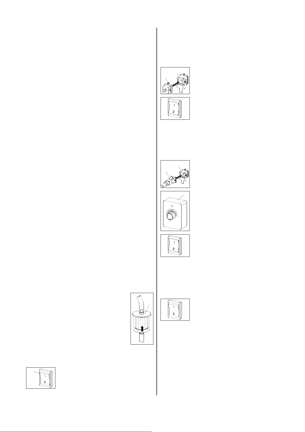
Heating without room thermostat
The unit runs in continuous operation.
4
3
Heating with room thermostat (accessories)
The unit runs fully automatically and depending on temperatures.
1. Connect the supplied bridge circuit
plug 3 to the thermostat socket 4 of
the unit
2. Put the operating switch into position
“1” (on).
◊ Use only appropriate and clean tanks to fill with fuel.
The unit is to be installed only in well aerated
rooms, but not in living rooms or similar recreation
G
rooms!
Paraffin accumulation by low outside temperatures
The supply of sufficient liquid fuel is to be ensured, even
with low outside temperatures.
Paraffin accumulation can occur even at temperatures as low as 5 °C. Appropriate measures must
G
be taken to avoid this.
◊ The built-in tank heating is only active as long as the
mains plug is connected with a functioning mains
socket.
◊ It is not possible to get rid of paraffin discharge
which is already present using the tank heating.
The requirement for this is the cleaning of the entire
fuel system.
Fuel filter
Prior to commissioning the unit and before
the tank is filled each time, the main filter (F)
must be checked for the presence of grime
or the accumulation of paraffin.
The main filter is positioning beside the filler.
Make sure to fill the fuel tank only with the
tank filter inserted into the filler neck.
F
4
5
1. Remove the bridge circuit plug 3.
2. Connect the thermostat plug 5 of the
room thermostat (accessories) into
the thermostat socket 4.
6
3. Install room thermostat 6 in a suitable place.
The thermostat sensor may not be
exposed directly to the hot air current and not fixed directly on a cold
surface.
4. Pre-select desired room temperature on the room thermostat
5. Put the operating switch into position
“1” (on).
Unit Shut Down
1. Put operating switch into position
“0” (OFF).
Attention, important hints to the after-cooling phase
The air supply fan continues running to cool down the
combustion chamber and then stops later.
Connect the unit with the current supply
1. Put operating switch 1 into “0”
1
position (OFF).
2. Connect unit plug to a suitable
mains socket.
230V/1~ 50 Hz.
The fan can start several times before final switching off.
Never interrupt (except in emergency situations)
the connection to the mains before the end of the
whole after-cooling phase.
G
Our guarantee does not cover damages caused
to the unit by overheating.
7
Page 8
Maintenance and Service
The unit is to be maintained regularly whereby some
fundamental rules are to be observed to ensure a long
service life and trouble-free operation.
After each heating period or even earlier, depending on
the deployment conditions, the entire unit including
combustion chamber and burner head must be cleaned
of soot sediments, dust and dirt.
The oil filters must also be cleaned / replaced at least
once a year or, depending on the degree of contamination of the fuel, frequently.
Prior to starting any work make sure to pull the
mains plug out of the mains socket!
G
Setting and maintenance is to be carried out
only by authorised personnel!
G
Cleaning the fuel tank
It is necessary to clean the fuel tank:
◊ After each heating period or, depending on the
deployment conditions, even earlier.
◊ Before and after extended idle periods.
◊ If the main filter frequently becomes dirty.
◊ If condensation water accumulates in the fuel.
Please proceed in the following way when cleaning the
fuel tank.
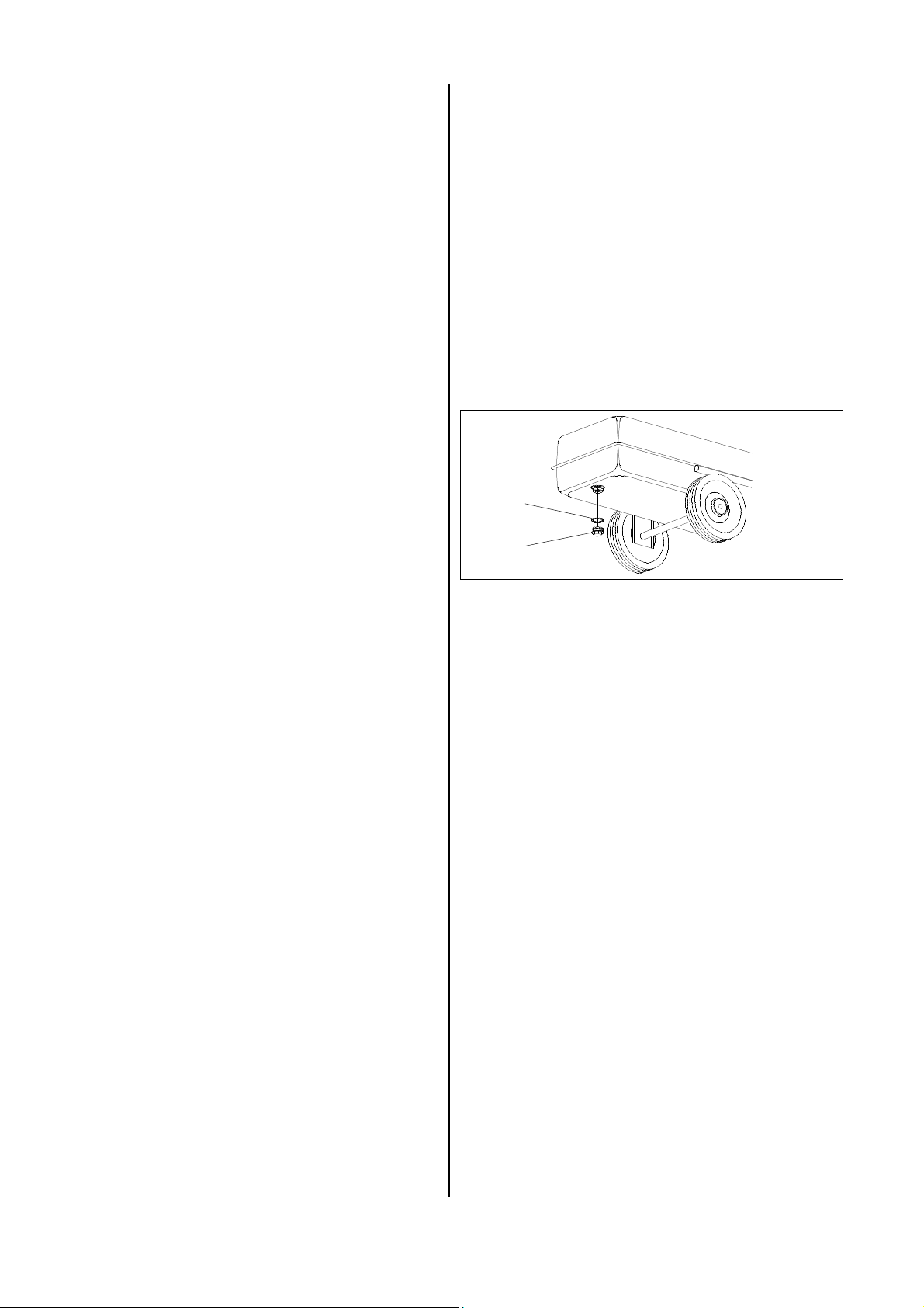
◊ Unscrew the discharging screw D (SW 22) and dis-
charge the fuel into a suitable vessel.
◊ The unit is to be kept free from dust and other de-
posits and is to be cleaned only with a dry or humid
cloth.
Do not use water jet.
◊ Do not use any aggressive cleaning agents or those
which are harmful or environmentally unfriendly.
◊ When the unit has not been used for a longer period,
the fuel tank is to be emptied, rinsed and to be filled
with clean fuel.
◊ Use only clean fuel oil EL and diesel, respectively.
Make sure to avoid paraffin formation.
◊ Empty fuel tank at least twice a year and rinse it with
clean fuel.
Do not use water!
◊ Keep burner head clean.
◊ Wearing parts such as e.g. oil filters, burner nozzle
and gaskets must be checked and, if necessary, replaced.
In any case, we recommend the replacement of the
oil jet before the start of each heating season.
◊ The oil filter in the filler neck of the fuel tank is to be
cleaned regularly.
◊ The main oil filter is to be replaced (take care of flow
direction) depending on the rate of pollution, but at
least before the start of every heating period.
The main filter is at the left side of the unit above the
fuel tank.
◊ Gauze oil filters have been installed in the fuel pump,
in the magnetic valve and in the burner nozzle.
These filters are to be cleaned by an expert.
◊ Check safety devices regularly.
◊ In the case of reducing heating capacity, formation of
smoke and/or bad ignition the unit is to be inspected
and the burner is to be adjusted.
◊ Observe regular maintenance and care intervals.
E
D
◊ Rinse the container several times if necessary with
clean fuel thoroughly.
Do not use water!.
◊ Please use no cleaning agents which contain
solvents.
These can destroy the inner layer of the tank.
◊ Avoid the use of high-pressure cleaners.
◊ Fit the discharging screw D (SW 22).
◊ The gasket ring E should be replaced after each
disassembly.
◊ Fill tank with clean fuel.
◊ Start unit and let it run for approx. 3 minutes.
Burner adjustment
Disassembly of burner head and nozzle
1. Loosen safety screw of burner head at combustion
chamber.
2. Loosen cap nut of fuel piping at burner head.
3. Remove photo cell and ignition cable, and remove
the burner head by turning from the rear wall of the
burner chamber.
Use only appropriate tools to disassemble the
nozzle (SW 16) and counteract at the blast con-
G
nection (SW 19).
8
Page 9
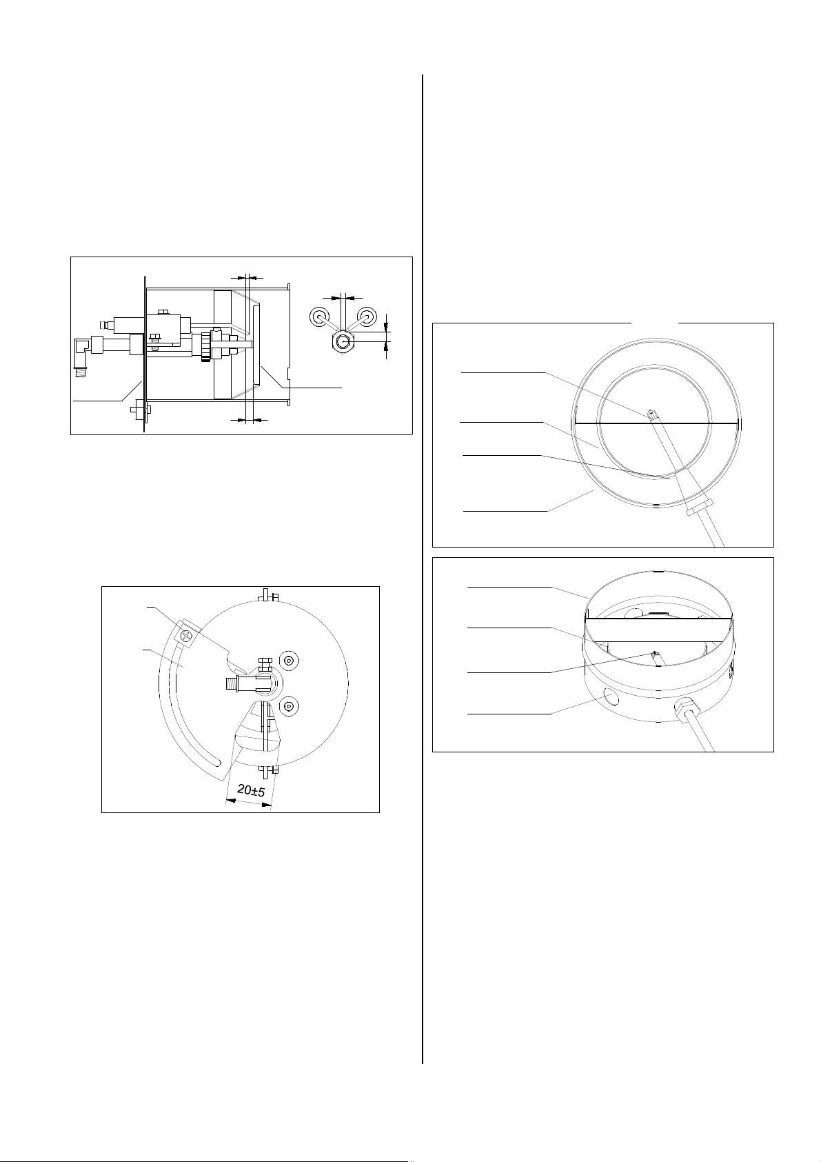
4. When maintenance has been carried out reassemble all parts carefully in reverse order.
5. Pre-set air flow plate, air slide plate and the ignition
electrode distance according to the approximate indications.
Adjustments of the burner head
2
3-4
Exhaust Measurement
On account of the construction-dependent design of the
exhaust connection (connection nozzle with secondary
air openings), it is not possible to perform a correct exhaust analysis in a conventional manner in the exhaust
pipe behind the exhaust connection.
For the performance of the exhaust analysis the sensor
of the exhaust-measurement device must be placed in
the centre of the pipe socket of the heat exchanger.
The measurement sensor is placed through the appropriate lateral secondary air opening in the exhaust connection in the existing measurement opening in the pipe
nozzle of the combustion chamber (see drawing below).
8
air flow
air slide
plate
4
plate
◊ Distance nozzle - air flow plate 4 mm
◊ Distance nozzle - electrode tip 2 mm
◊ Distance centre of nozzle - electrode tip 8 mm
◊ Distance between the electrode tips 3-4 mm
Coarse adjustments of the air slide plate
S
L
Drawing top-view
measurement
sensor
pipe socket
measurement
opening
exhaust
connection
exhaust
connection
pipe socket
measurement
sensor
auxiliary air
opening
1. Loosen the safety screw S.
2. Set the air slide plate L by turning to an opening
width of ca. 25 mm.
3. Tighten the safety screw again.
Fine adjustment of air slide plate
Fine adjustment of air slide plate by means of CO2 indi-
cator and soot pump.
CO2 - value: approx. 10 - 13 %
Soot figure: 0 - 1 (by Bacharach)
Service and Guarantee
Any claims under guarantee regarding materials can be
accepted only when the orderer or his customer has
filled in completely the “guarantee certificate” which is
enclosed with every REMKO-heater and has returned it
to REMKO GmbH & Co. KG in due time after the unit’s
sale and commissioning.
The units are factory tested on faultless function. If any
failures occurs though which cannot be eliminated by the
operating person, please contact your dealer or contact
person.
An operation/use other than that indicated in these instructions is prohibited!
In the case of non-observation we will not be held responsible and our guarantee will become void.
9
Page 10
Fuel Pump
The standard type of the pump runs in a system of
1 pipe. The required fuel is sucked in through the suction
line "S".
For the first starting and after having emptied the fuel
tank, the fuel system is deaerated through the burner
nozzle.
For this purpose the unit is switched on. After a possible
switch off through failure, the unit is restarted after having released the automatic burner relay (take care of
waiting time).
If, after the 3rd start of the unit there is another switch
off through faults, the fuel filters should be checked to
make sure that they are free from pollutions and that
they are tight.
Filter
S
Perfect fuel quality is an absolute necessity for the
lubrication of the pump drive.
Suction of water residues should never take place
G
and, in the case of setting, suction should not take
place of warping fine dusts (e.g. cement etc.).
Gasket
Cover
Technical Data
Model AT 25
Nominal heat output max. kW 25
Nominal heat output kW 22,5
Air output m³/h 1020
Increase of temperature ∆t
Fuel Heating oil EL or Diesel
Fuel consumption, max. kg/h 2,1
Nozzle (70°W / 80°S) USG 0,6
Pump pressure approx. bar 9 - 10
Tank capacity Ltr. 40
Electrical connection 1~ V 230
Frequency Hz 50
Rated current max. A 1,6
Power consumption max. 1)
Fuse protection (required) A 10
Sound pressure level L
Exhaust connection ∅
Length mm 1250
Width mm 485
Height mm 685
Weight kg 58
1) unit inclusive tank heating
2) noise measuring (when heating) DIN 45635 - 01 KL 3
pA 1m
K 54
kW 0,32
2)
dB(A) 74
mm 150
Wiring Diagram
Never let the pump run without feeding fuel for a
longer period. Make sure not to leave a unit with
G
dry run pump unattended for a longer time.
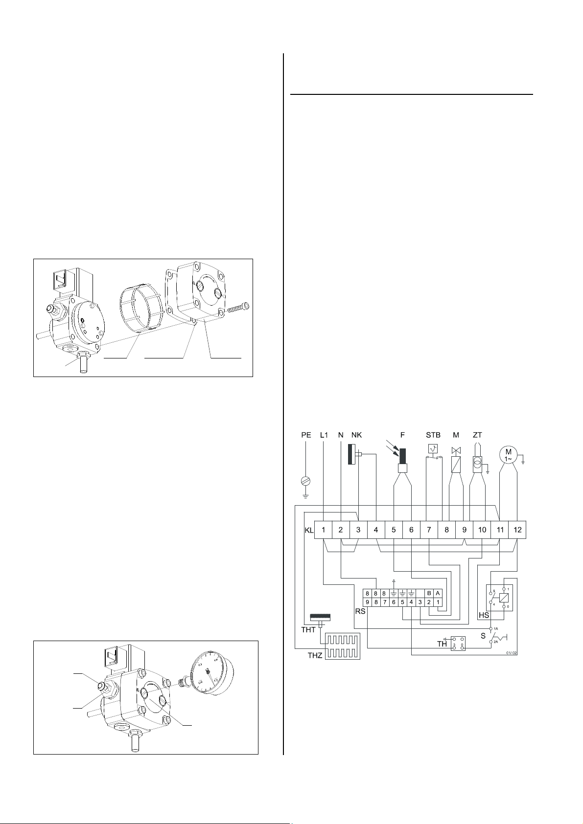
Setting the pump pressure
The pump pressure can only be set if a manometer is
connected to the connection P. The pump pressure is
changed by turning the pressure setting screw A:
clockwise: increase the pressure.
counter clockwise: reduce the pressure.
The required pump pressure is determined according to
the heating capacity (please refer to unit type plate) and
to the nozzle size. The pressure setting screw "A" is to
be secured with the counter nut "B" after having set the
pressure.
A
B
P
F = photo cell
HS = auxiliary relay
KL = terminal strip
M = motor
MV = solenoid valve
NK = recool thermostat
RS = relay socket
S = operating switch
STB = safety temperature
limiter
TH = thermostat socket
THT = thermostat (tank heating)
THZ = tank heating
ZT = ignition transformer
10
Page 11
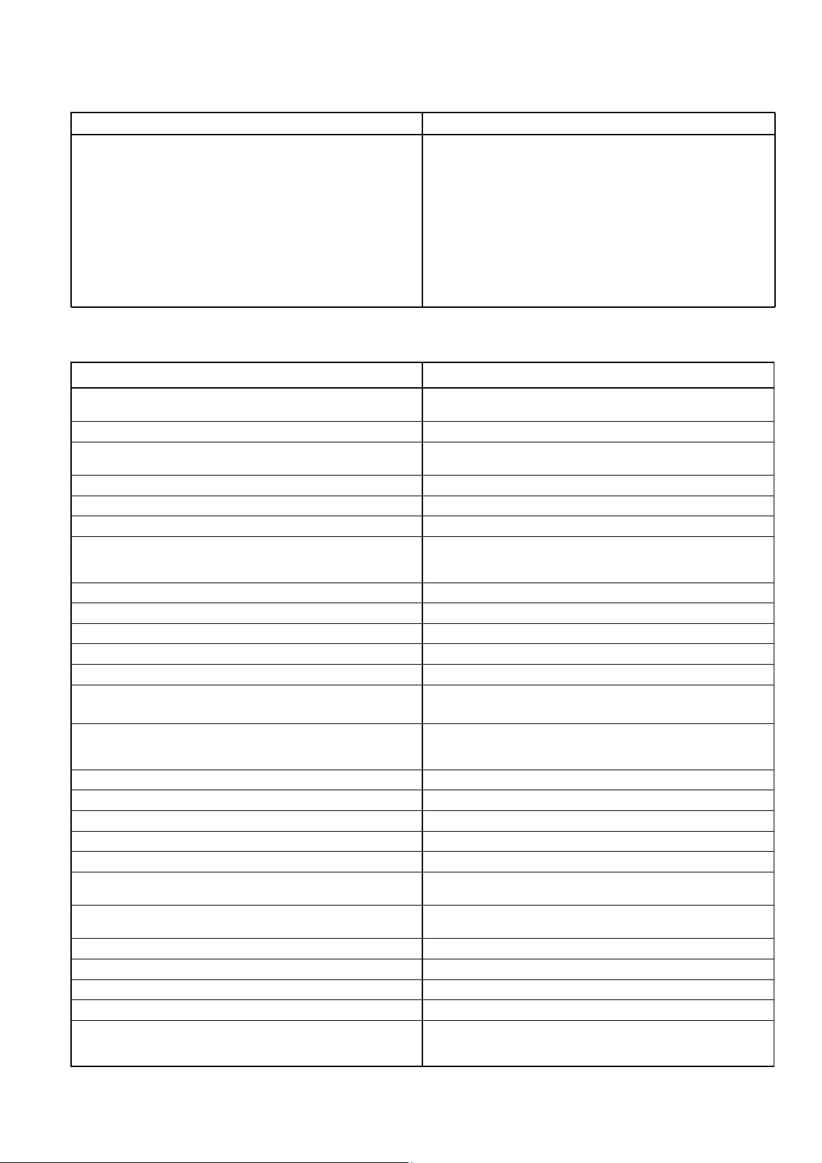
Troubleshooting
Cause: Trouble:
– unit does not start.
– fan motor is running but burner will not be ignited.
– unit shut down without flaming formation.
– unit stops during operation.
(fault indicator lamp of the automatic burner relay lights up)
– smoke forming at the blow-out cone.
– unit can’t be switched off..
2 – 3 – 4 – 6 – 7 – 8 – 25
1 – 5 – 9 – 10 – 11 – 12 – 13 – 14 – 15 – 16 – 17
20 – 21 – 23 – 24 – 26
20
4 – 5 – 6 – 7 – 8 – 9 – 10 – 11 – 13 – 15 – 16 – 17
19 – 21 – 22 – 23 – 24 – 26
7 – 10 – 11 – 13 – 15 – 17 – 19 – 21 – 22 – 24
18 – 25
The mains plug has been taken out of the mains socket before carrying out any work regarding the unit.
G G
Setting and maintenance is to be carried out only by authorised experts!
Cause: Remedy:
1. Air (bubbles) in the fuel system during starting procedure.
2. No electrical connection. – Check mains, mains plug and current.
3. No (bridge circuit-/thermostat-) plug in the thermostat socket.
4. Thermostat setting is too low. – Set thermostat higher than the room temperature.
5. Fault indicator lamp of the automatic burner relay lights up. – Unlock the automatic burner relay by pressing the reset button.
6. Faults in the automatic burner relay. – Replace automatic burner relay.
7. Fan motor is overcharged.
(Fan blows irregularly or is blocked)
8. Fuel pump is blocked. – Check resp. replace fuel pump.
9. Fuel tank is empty. – Fill fuel tank with clean fuel.
10. Fuel filter is blocked (dirty). – Clean fuel filter resp. replace if necessary.
11. Nozzle is blocked resp. wrong dimension (type/size). – Replace nozzle (take care of correct type and size!).
12. Wrong setting of ignition electrodes or damaged insulation. – Adjust correctly resp. replace it.
13. Air flow plate of the burner head is misadjusted resp. dirty.
14. Solenoid valve does not open.
15. Misadjusted pump pressure. – Set pump pressure by means of a pressure-gauge.
16. Pump clutch is defective. – Replace pump clutch.
17. Leakage in suction pipe or in fuel filter. – Check suction pipe and fuel filter, replace if necessary.
18. Solenoid valve does not close. – Pull off the fuel pipe from the main filter - the flame dies.
19. Air protecting grille is dirty. – Clean air protecting grille.
20. Disconnection by the safety temperature limiter (STB).
21. Air (bubbles) in the fuel system.
22. No adequate ventilation. – Open doors or windows.
23. Photo cell is dirty resp. defective. – Clean photo cell resp. replace if necessary.
24. Improper exhaust system. – See chapter “Exhaust system“.
25. Operating switch not functioning. – Check operating switch resp. replace if necessary.
26. Fuel with paraffin accumulation.
(Already occur starting from 5 °C see notes in chapter "Starting").
The tank heating is damage (very rarely).
– Press fault clearance button of the automatic burner relay,
repeat if necessary (max. 3 x).
– Connect bridge circuit plug resp. thermostat plug with the thermostat
socket.
– Let motor cool down.
– Check slight run of fuel pump.
– Check motor on electrical and mechanical function.
– Adjust correctly by means of CO2 –indicator and soot pump
(CO2 : 10 – 13% and soot figure by Bacharach: 0 – 1).
– Check solenoid valve resp. replace if necessary.
(A „click“ should be heard during switching on/off)
– The safety temperature limiter has released / is defective.
– Check air protecting grille, clean if necessary.
– Unlock safety temperature limiter (STB-Reset).
– Restart the unit in order to discharge the air through the nozzle.
(This procedure can be repeated up to max. 3 times).
– Clean the entire fuel system.
– Replace the damage tank heating.
11
Page 12
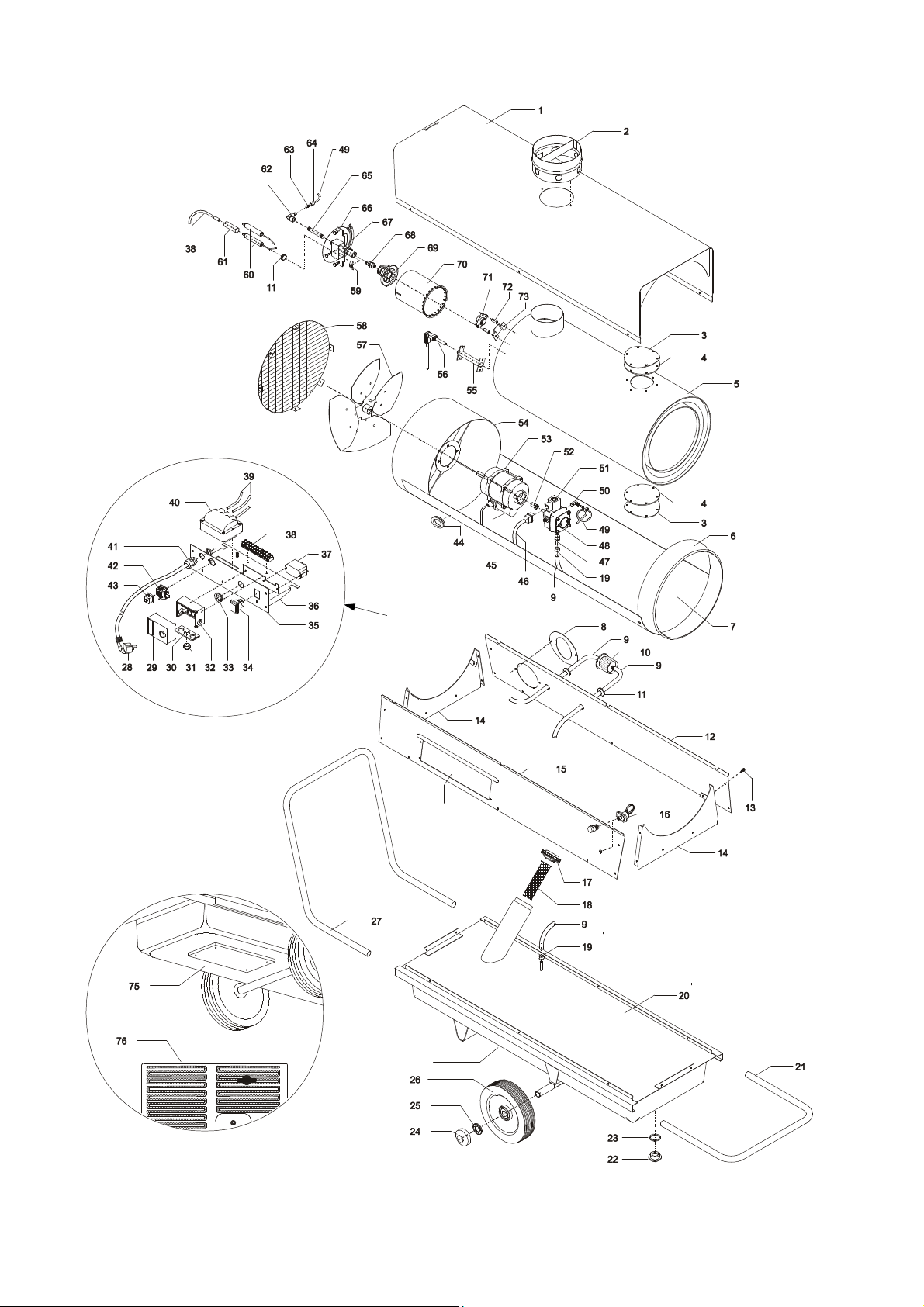
Exploded View
Fig. A
74
See fig. A
See fig. B
12
Fig. B
We reserve the right to make modifications in dimensions and construction in the interests of technical progress.
Page 13

Spare Part List
Description
No.
Ref-No.
No.
Description
Ref-No.
1
inspection cover
2
exhaust connection
3
inspection cover
4
gasket (inspection cover)
5
combustion chamber
6
blow-out connection
7
housing base
8
cover (filler neck)
9
fuel hose (running metres)
10
fuel filter
11
protective socket, small
12
side cover, left
13
fastening screw
14
cover, front / back
15
side cover, right
16
safety temperature limiter
17
filler cap
18
fuel filter (filler neck)
19
hose clamp
20
fuel tank cpl. (with tank heating)
21
transport handle, front
22
drain screw
23
gasket ring (drain screw)
24
wheel cap
25
wheel lock ring
26
wheel
27
transport handle, back
28
connecting cable with plug
29
automatic burner relay
30
PG-plate
31
locking screw (PG-plate)
32
relay socket
33
protective socket
34
operating switch
35
cover
36
mounting plate
37
auxiliary relay
38
terminal strip 12 x
39
ignition cable, kit
40
ignition electrode
41
traction relief
1103701
1103702
1103703
1103705
1103704
1103706
1103707
1102925
1102156
1102146
1102131
1103708
1102937
1103709
1103710
1103711
1102148
1102149
1102157
1103727
1102932
1102152
1102151
1101623
1101622
1102155
1102931
1101320
1102239
1102533
1103716
1102534
1101528
1102248
1103713
1103714
1102137
1103715
1102159
1102132
1108325
42
43
44
45
46
47
48
49
50
51
52
53
54
55
56
57
58
59
60
61
62
63
64
65
66
67
68
69
70
71
72
73
74
75
76
Not
shown
thermostat socket
bridge circuit plug
protective socket, big
capacitor
connection cable (solenoid valve)
hose connection fitting
fuel pump (with solenoid valve)
copper pipe 4 mm, cpl.
angle clutch 1/8“ x 4
solenoid valve
pump clutch
fan motor
fan housing
photo cell holder
photo cell
fan blade
protecting grille
clamp (ignition electrode)
ignition electrode
protection hose
angle clutch
cutting ring 4 mm
sleeve nut 4 mm
connection pipe
air slide plate
holder (nozzle)
nozzle
air flow plate
burner head
recool thermostat
distance sleeve
clamp (thermostat)
electric board cpl. (slide in)
cover (tank heating)
tank heating cpl.
cover gasket (fuel pump)
fuel filter (pump)
plastic screw (pump)
fuel filter with shut-off valve (2 pipes)
thermostat plug
1101018
1101019
1101615
1102907
1102825
1102109
1103717
1102315
1102112
1103718
1102936
1102905
1103719
1102126
1108209
1103720
1103721
1102120
1102118
1101617
1102116
1102908
1102909
1102117
1103722
1102121
1102923
1102122
1103723
1101027
1103724
1102128
1103726
1102258
1102256
1108454
1108409
1103725
1102526
1101020
When ordering spare parts please indicate ref.-no. and machine no. (see type plate)!
13
Page 14

Maintenance Log
Model : ................................ Model No. : ......................................
1 2 3 4 5 6 7 8 9 10 11 12 13 14 15 16 17 18 19 20
Clean unit -surfaceClean unit -interiorClean fan
Clean combustion chamber
Clean burner head
Adjust ignition electrode
Replace nozzle
Clean / replace fuel filter
Adjust / measuring burner
Check safety facility
Check protection guards
Check unit for damage
Check fastening screws
Electric safety-inspections
Test run
Remarks: ......................................................................................................................................................................
......................................................................................................................................................................................
1. Date: ...................... 2. Date: ...................... 3. Date: ...................... 4. Date: ...................... 5. Date: ......................
.................................. ................................... ................................... ................................... ...................................
Signature Signature Signature Signature Signature
6. Date: ...................... 7. Date: ...................... 8. Date: ...................... 9. Date: ...................... 10. Date: ....................
.................................. ................................... ................................... ................................... ...................................
Signature Signature Signature Signature Signature
11. Date: .................... 12. Date: .................... 13. Date: .................... 14. Date: .................... 15. Date: ....................
.................................. ................................... ................................... ................................... ...................................
Signature Signature Signature Signature Signature
16. Date: .................... 17. Date: .................... 18. Date: .................... 19. Date: .................... 20. Date: ....................
.................................. ................................... ................................... ................................... ...................................
Signature Signature Signature Signature Signature
Setting and maintenance work is to be carried out only by authorised specialists!
14
Page 15

Page 16

REMKO GmbH & Co. KG
Klima- und Wärmetechnik
D-32791 Lage • Im Seelenkamp 12
D-32777 Lage • PO Box 1827
Phone +49 (5232) 606 - 0
Fax +49 (5232) 606260
 Loading...