

Page 1
REMKO AMT
REMKO AMT
45-E to 115-E
Air dehumidifiers
Operation · Technology · Spare parts
Edition GB – D09
Page 2

Page 3
Contents
Air dehumidification
Safety notes
Intended use
Customer service and guarantee
Environmental protection and recycling
Unit description
Set-up
Commissioning
Shutdown
Transportation
Care and maintenance
Troubleshooting
Electrical wiring diagram
4
6
7
7
7
8
9
10
12
13
13
14
15
Exploded view of the AMT 45-E unit
Spare parts list AMT 45-E
Exploded view of the AMT 65-E and 85-E units
Spare parts list AMT 65-E and 85-E
Exploded view of the AMT 115-E unit
Spare parts list AMT 115-E
Maintenance protocol
Technical data
Carefully read this operating manual prior to commissioning/using
the unit!
This operating manual is a translation of the German original.
16
17
18
19
20
21
22
23
Made by REMKO
These instructions are an integral part of the unit and must always be
kept in the vicinity of the installation location or on the unit itself.
Subject to modifications; no liability accepted for errors or misprints!
3
Page 4
REMKO AMT
Air dehumidification
The correlations occurring when
air is dehumidified are based
on physical laws.
These are depicted here
in graphical form in order
to provide you with a brief
overview of the principles of air
dehumidification.
The use of
REMKO air dehumidifiers
– Even if windows and doors
are well insulated, water and
moisture are still capable of
penetrating thick concrete walls.
– The water required for setting
in the production of concrete,
mortar and plaster etc. may only
be diffused after 1-2 months.
– Even moisture trapped
in the masonry after highwater or a flood is released very
slowly.
– The same is also true of
moisture contained in stored
materials for example.
The moisture (water vapour)
released from parts of a building
or materials is absorbed by
the surrounding air. As a result,
the moisture content increases,
which ultimately gives rise
to corrosion, mould, rot, peeling
of paint and other unwanted
damage.
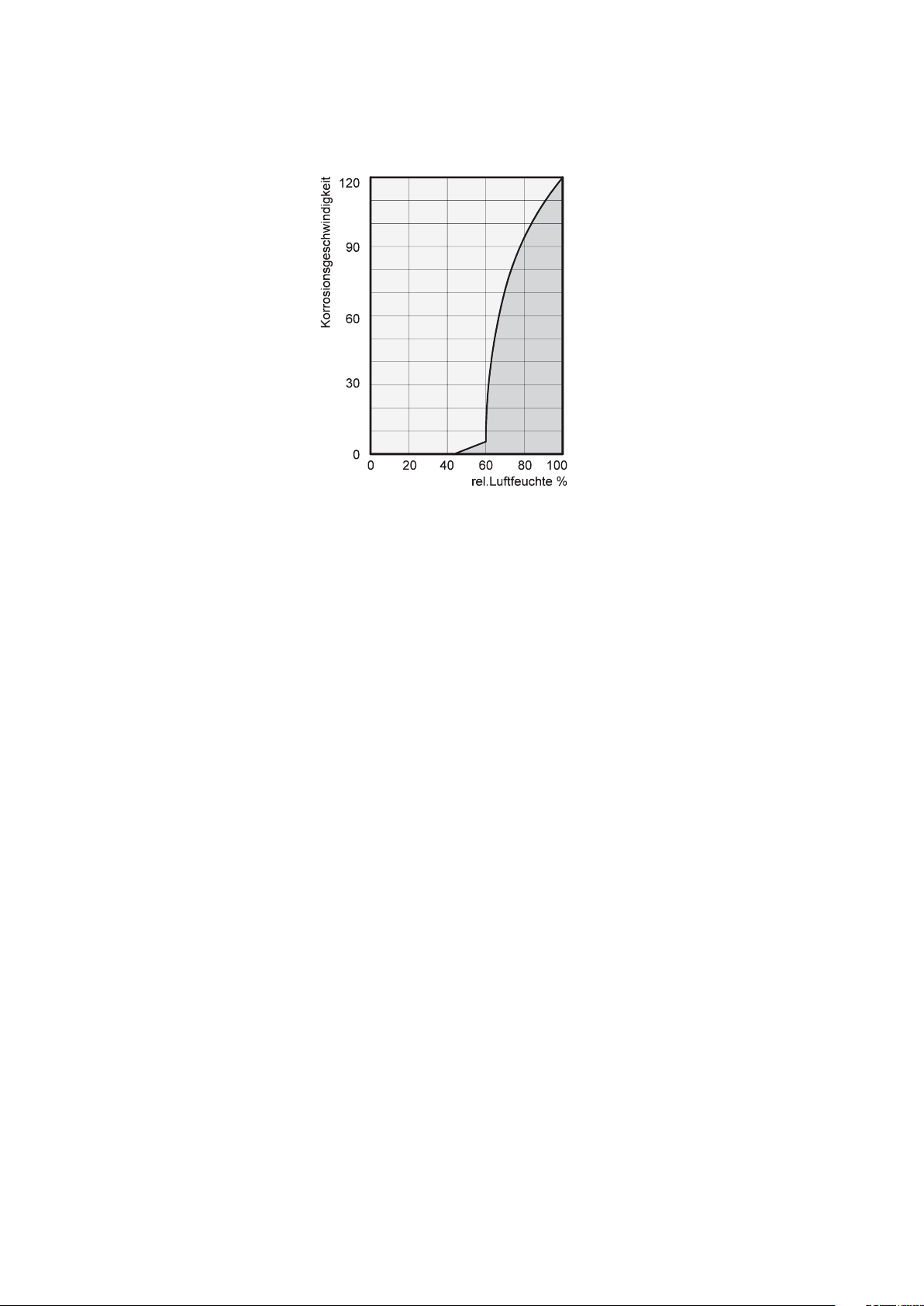
By way of example, the diagram
shows the corrosion rate of metal
in different levels of humidity.
It is evident that the corrosion rate
below 50% relative humidity
(RH) is low, and below 40% is
negligible.
The corrosion rate increases
significantly above 60% RH.
This threshold for damage
as the result of humidity also
applies to other materials, such
as powdery substances, packaging,
wood and electronic units.
Buildings may be dried in a variety
of ways:
1. By heating and
air exchange:
The air in the room is heated
in order for moisture to be
removed and then this air is fed
outside. All of the energy that is
involved is lost together with
the moist air that is released.
2. By air dehumidification:
The moist air that is
present within an enclosed
space is continuously
dehumidified according
to the condensation principle.
With regard to energy
consumption, air
dehumidification has one distinct
advantage:
Energy expenditure is limited
exclusively to the air volumes
present. The mechanical
heat that is released by
the dehumidification process is fed
back into the room.
Under normal use, the
dehumidifier
25% of the energy that is
required for the
ventilating" principle.
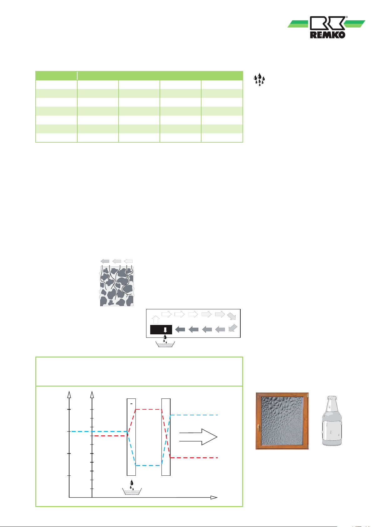
Relative air humidity
Our ambient air is a gaseous
mixture which always contains
a certain volume of water
in the form of water vapour.
This volume of water is specified
in g per kg of dry air (absolute
moisture content).
1m3 of air weighs approx. 1.2 kg
at 20°C
Depending on the temperature,
each kg of air is only capable
of absorbing a certain volume
of water vapour. Once this
capacity has been reached, the air
is referred to as "saturated"
and has a relative humidity (RH)
of 100%.
Relative humidity is understood
to mean the ratio between
the current quantity of water
vapour in the air and the maximum
possible quantity of water vapour
at the same temperature.
The ability of the air to absorb
water vapour increases
as the temperature rises.
I.e. the maximum possible
(absolute) water content becomes
greater as the temperature rises.
uses approximately
air
"heating and
4
Page 5
Temp. Water vapour content in g/m3 at humidity of
Verdampfer Kondensator
°C
30
25
20
15
% r.F.
100
90
80
70
60
50
40
30
20
10
+
+
-
Lufttemperatur
Luftfeuchte
Verlauf
Luftrichtung
°C 40% 60% 80% 100%
-5 1.3 1.9 2.6 3.3
+10 3.8 5.6 7.5 9.4
+15 5.1 7.7 10.2 12.8
+20 6.9 10.4 13.8 17.3
+25 9.2 13.8 18.4 23.0
+30 12.9 18.2 24.3 30.3
Drying of materials
Building materials and structures
are capable of absorbing
considerable volumes of water,
such as brick 90-190 l/m³, heavy
concrete 140-190 l/m³ and
limestone 180-270 l/m³.
The drying of moist materials such
■
The air containing water vapour
is constantly circulated through
the REMKO air dehumidifier.
The air is dehumidified and,
slightly heated, leaves the unit
in order to re-absorb water
vapour
as masonry is effected as follows:
■
In this way, the moisture
■
The moisture moves
from the inside
of the material
contained in the material
is reduced gradually.
The material is dried!
to its surface
The accumulated condensate is
■
Evaporation occurs
on the surface =
collected in the unit from where
it is drained off.
Transfer of water vapour
to the ambient air
The condensation of
water vapour
Because the capacity
for the maximum possible volume
of water vapour increases as the air
is heated, the volume of water
vapour contained remains constant
and so relative humidity falls.
In contrast, because the capacity
for the maximum possible volume of
water vapour decreases as the air is
cooled, the volume of water vapour
contained remains constant and so
relative humidity increases.
If the temperature continues to fall,
the capacity for the maximum
possible volume of water vapour
is reduced so much so that it is
ultimately equal to the volume of
water vapour contained in the air.
This temperature is referred
to as the dew point. If the air is
cooled to below the dew point,
the volume of water vapour
in the air will become greater
than the maximum possible volume
of water vapour.
At this point, the water vapour
begins to precipitate.
It then condenses to water.
Humidity is then removed from
the air.
As it flows through or over the evaporator, the air stream is cooled
to dew point. The water vapour condenses, and is collected
in a condensate trap from where it is drained off.
Examples of condensation include
steamed-up window panes in winter,
or the moisture on the outside of
a cold drinks bottle.
As the relative humidity of the air
increases, so to does the dew point,
making it easier for the temperature
to fall below it.
5
Page 6

REMKO AMT
Condensation heat
The Energy transferred to the air
from the condenser consists of:
1. the amount of heat derived
beforehand in the evaporator.
2. the electrical drive energy.
3. the condensation heat released
by the liquefying of the water
vapour.
Energy must be supplied when
liquid is converted into a gas.
This energy is designated
as evaporation heat. It does not
cause any increase in temperature,
Safety notes
but is required to convert a liquid
into a gas.
Conversely, energy is released
when gas is liquefied, this is
designated as condensation heat.
The amount of energy
from evaporation heat and
condensation heat is the same.
For water, this is:
2250 kJ/kg (4.18 kJ = 1kcal)
From this it is evident
that the condensation of water
vapour causes a large quantity
of energy to be released.
With drying operations,
a heat cycle is created,
whereby heat is consumed
for evaporation and released
for condensation.
Generally speaking, the time
required for the drying process is
not only dependent on the output
of the unit, but is determined
to a greater extent by the speed
at which the material or building
section loses its moisture.
The units were subjected
to extensive material, functional
and quality inspections prior
to delivery.
However, dangers can result
from the units if they are used
improperly or not as intended by
untrained personnel.
The following notes must be
observed in full:
■
The units may not be installed
or operated in explosive
environments
■
The units must not be installed
or operated in atmospheres
containing oil, sulphur, chlorine
or salt
■
The units must be installed
upright and in a stable position
■
An unobstructed air inlet and
air outlet must be guaranteed
at all times
■
The air-inlet grille must always
be kept free of dirt and loose
objects
■
The units must not be covered
during operation
■
Never stick foreign objects
into the units
■
The units must not be
transported while they are
running
■
The units must only
be transported when
the condensate container is
empty and the evaporator is dry
■
Before each change of location,
the condensate container must
be emptied
!
ATTENTION
Extensions
to the connection cable
must only be conducted
by authorised specialist
electricians, taking
into consideration the unit
power consumption, cable
length and local use.
!
ATTENTION
Work on the refrigerant
system and on the electrical
equipment must only be
conducted by a speciallyauthorised specialist!
■
The units must not be exposed
to direct jets of water
6
■
All electrical cables
on the outside of the units must
be protected against damage
(e.g. by animals etc.)
Page 7

Intended use Environmental
The units are designed
exclusively for drying and
dehumidification purposes
in industrial or commercial
situations on the basis of their
structural design and equipment.
The units must only be operated
by appropriately instructed
personnel.
With non-observance
of the manufacturer's
specifications, the respective
local legal requirements or after
arbitrary alterations to the units,
the manufacturer shall not be
liable for resulting damages.
Customer service and
Guarantee
As a prerequisite for any guarantee
claims to be considered, it is
essential that the ordering party
or its representative complete
and return the "certificate of
guarantee" to REMKO GmbH &
Co. KG at the time when the units
are purchased and commissioned.
The units were tested
at the factory
several times to verify their correct
function.
However, if malfunctions should
arise that cannot be remedied by
the operator with the assistance of
the troubleshooting section, please
contact your specialist dealer or
contractual partner.
protection
and recycling
Disposing of packaging
When disposing of packaging
material, please consider our
environment.
Our units are carefully packed
and delivered in stable cardboard
transport packaging and, if
applicable, on a wooden pallet.
The packaging materials are
environmentally-friendly and
can be recycled.
By recycling packaging
materials, you make a valuable
contribution to the reduction of
waste and conservation of raw
materials.
Therefore, only dispose of
packaging material at appropriate
collection points.
NOTE
Operation other than the types
listed in this operating manual
is prohibited.
With non-observance, any
liability and claim to guarantee
expire.
!
ATTENTION
Copyright
The redistribution, even
in part, or the use of this
documentation for purposes
other than intended without
the written authorisation of
REMKO GmbH & Co. KG
is prohibited.
NOTE
Adjustment and maintenance
work may only be carried
out by authorised qualified
technicians.
Important information
concerning recycling
The units are operated with
environmentally-friendly and
ozone-neutral R410A refrigerant.
The mixture of refrigerant and oil
within the unit must be disposed
of properly in accordance with
the statutory or locally-applicable
regulations.
Disposal of the old unit
The manufacturing process
for the units is subject
to continuous quality control.
Only high-grade materials are
processed, the majority of which
are recyclable.
You also contribute
to environmental protection by
ensuring that your old
equipment is only disposed of
in an environmentally-friendly
manner.
Therefore, only bring the old
unit to an authorised recycling
business or to an appropriate
collection point.
7
Page 8
REMKO AMT
Unit description
The units have been designed
for universal and straightforward
air dehumidification.
Their compact dimensions allow
the unit to be transported and set
up with ease.
The units operate in accordance
with the condensation principle
and are equipped with
a hermetically sealed refrigerant
system, low-noise and lowmaintenance fan, operating hours
counter and connection cable with
plug.
Fully-automatic electronic control,
a condensate container
with integrated overflow
protection (not AMT 115-E)
in addition to connection ports
for direct condensate drainage
help to ensure continuous faultfree operation.
The units conform
to the fundamental health
and safety requirements of
the appropriate EU stipulations.
The units are dependable and offer
ease of operation.
Locations at which units are
used
The units are used in all locations,
where dry air is a must and where
economic consequential damage
(such as that caused by mould)
must be prevented.
Operating sequence
Switching on the units
puts the electrical control
into operation.
The green indicator light
on the operating switch
illuminates.
Due to an automatic pressure
equalisation, the units start with
a time delay of around 10 seconds.
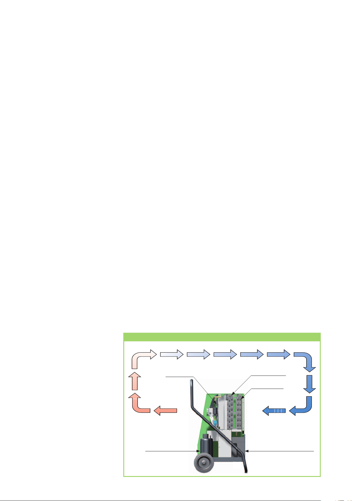
The fan extracts the moist room air
through the dust filter, evaporator
and the condenser behind.
Heat is removed from the room air
on the cold evaporator. The air is
then cooled to below dew point.
The water vapour contained
in the room air is then
deposited as condensate or rime
on the evaporator fins.
If the temperature sensor here
measures a pre-set minimum, it
activates a timer with a 30 minute
delay.
If the evaporator temperature
stops increasing during this period,
the cooling cycle switches to hot
gas defrosting after the timer
cycle.
The fan remains out of
operation during the defrosting
phase.
Schematic depiction of the workings of a REMKO air dehumidifier
As soon as the rime (ice) has been
defrosted and the temperature
at the probe has increased,
the unit switches back to normal
dehumidification mode.
If the room temperature is
sufficiently high, the surface
of the fins will not be cold enough
for rime formation to occur,
rendering defrosting unnecessary.
Therefore, the air dehumidifiers
work economically.
The cooled and dehumidified air
is re-heated by the condenser
(heat exchanger), and blown back
into the room through the outlet
grille.
The processed, dry, heated air then
re-mixes with the room air.
Continuous circulation of the room
air through the unit gradually
reduces the relative humidity (%
RH) in the room to the desired
humidity level.
Depending on the room
temperature and the humidity,
only 30 - 40% electrical energy
is required, in accordance with
the output of the unit.
The units may be used
for the drying and
dehumidification of areas such as:
■
New buildings, industrial
buildings
■
Basements, storage rooms
■
Archives laboratories
■
Weekend homes, caravans
■
Bathrooms, wash rooms and
changing rooms etc.
8
Fan
Dehumidified
room air
Compressor
Condenser
Evaporator
Moist room air
Condensate
container
Page 9

Set-up
For the best economic and safe use
of the units, the following notes
must be followed in full:
■
The units must be set up
in an upright and level position,
to ensure that the condensate
can drain freely
■
To ensure optimum air
circulation, the units should be
set up in the centre of the room,
where possible
■
It must be ensured that the air
can be sucked in on the front
of the unit and blown out of
the rear of the unit without
obstruction
■
Observe a minimum clearance
of 50 cm from walls at all times
■
Units must never be set up
in the immediate vicinity of
heaters or other sources of heat
■
The room being dried or
dehumidified must be closed
to the neighbouring atmosphere
■
Air circulation is improved if
the unit is set up approx. 1 m
above the ground
■
Avoid having opened windows
and doors etc., and avoid
frequent entry to or exit from
the room as much as possible
■
If the units are to be used
in dusty environments,
appropriate care and
maintenance measures
should be taken according
to the relevant conditions
■
The output of the unit is entirely
dependent on the conditions
inside the room, room
temperature, relative humidity
and observance of the set-up
instructions
■
The units may not be used
in environments containing
a great deal of dust or chlorine,
or in places with atmospheres
containing ammonia
Electrical connection
■
The units are operated
with 230 V / 50 Hz
alternating current
■
The electrical connection is
made using a built-in mains
cable with earthed safety plug
NOTE
The electrical connection
to the units must be made
at feedpoints with residual
current devices in accordance
with VDE 0100, Section 704.
When installing the units
in extremely damp
environments such as laundry
rooms, showers etc., the unit
must secured with a residual
current device provided
by the customer in accordance
with the regulations.
■
Extensions
to the connection cable
may only be carried out by
authorised electricians, subject
to the length of the cable,
connected load of the unit and
taking into consideration how
the unit is used at its location
Keep windows and doors closed!
Wall clearance
min. 0.5 m
Maintain adequate clearance from
heaters or other sources of heat.
!
ATTENTION
All cable extensions must only
be used in fully un-reeled or
reeled off condition.
9
Page 10
REMKO AMT
Commissioning
Before commissioning the unit or if
local requirements dictate, the airinlet grille and air-outlet grille must
be checked for contamination.
NOTE
A contaminated grille or filter
must be cleaned or replaced
immediately.
Important notes prior
to commissioning
■
All extensions to the electrical
connection must be of
a sufficient cable size and must
only be used fully rolled out or
unrolled
■
Never use the power supply
connection cable as a pull cord
■
After being switched on,
the units operate fullyautomatically until switched
off by the float when
the condensate container is full
(not AMT 115-E)
■
The condensate container must
be inserted properly
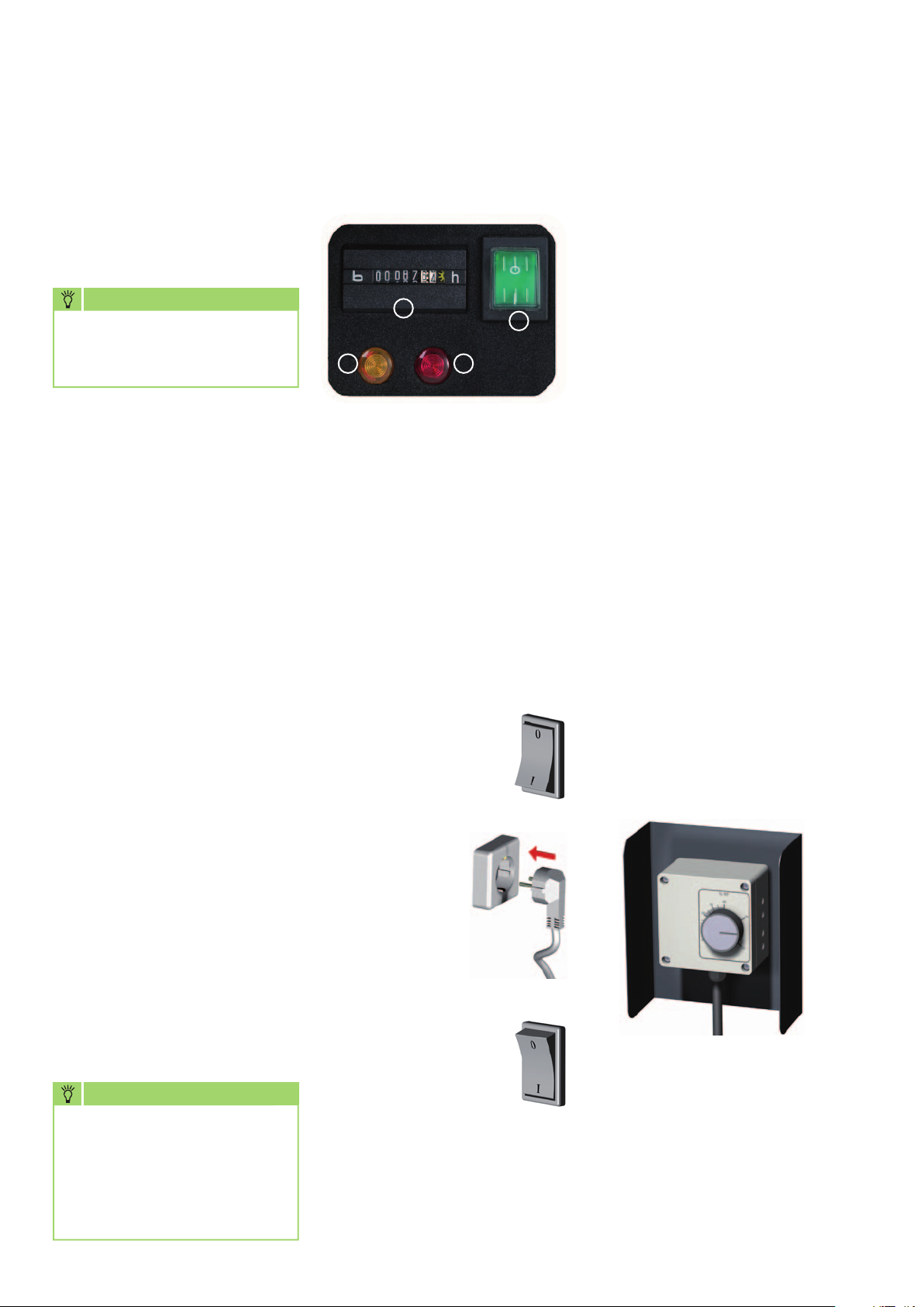
Control panel
1
3
1 = Operating hours counter
2 = Operating switch with
"Indicator light"
3 = -YELLOW- indicator light
"Container full"
4 = -RED- indicator light
„Malfunction / overheating"
Starting the unit
1. Move the operating
switch [2] to the "0"
(off) position.
4
2
Operation with a humidity
switch
The REMKO humidity switch
(accessories) is supplied with
a special adapter.
The following procedure must
be followed when commissioning
units in conjunction with
a humidity switch:
1. Insert the adapter
into a properly fused mains
socket.
2. Place the humidity
switch in a suitable
location within the room
being dehumidified.
Not in the immediate vicinity of
the units or sources of heat.
3. Insert the power plug (or a cable
extension) into the adapter.
4. Set the desired air humidity
on the humidity switch.
5. Move the operating switch [2]
on the unit to position "I".
The units will switch on
automatically when the air humidity
in the room exceeds the pre-set level
on the humidity switch.
■
In order to prevent damage
to the condenser, the units are
equipped with a mechanism
that prevents the compressor
from being immediately
switched back on after it is
switched off
The compressor does not
switch back on until after
a waiting time of around one
minute!
NOTE
In room temperatures below
10°C
and relative humidity
below
of the unit can no longer be
guaranteed.
10
40%
, economical use
2. Connect
the unit's power
plug to a properly
installed and
fused mains
socket.
230V/50 Hz
3. Move the operating
switch [2]to the "I"
(on) position.
The green indicator light
on the switch [2] illuminates.
The units switch on with a time
delay of around 10 seconds and
then run in permanent operating
mode.
The units will now operate fullyautomatically until the desired
relative humidity (% RH) has been
reached or until the unit is
switched off by the float when
the condensate container is full
(not AMT 115-E). In the event
that this occurs, the yellow
"Container full" indicator light will
illuminate.
Page 11
Condensate
Depending on the air temperature
and the relative humidity, condensed
water will drip into the condensate
trap or into the condensate
container either continuously or only
during the defrosting phases.
The condensate is fed
into the condensate container below
via a connection nozzle (not AMT
45-E and AMT 115-E).
A float is located inside
the condensate container.
In the event that the container is
full, the float will activate a water
stop switch which will switch off
dehumidification mode.
To guard against accidental stops
caused by flooding water etc., this
switch does not activate until after
a time delay of 10 seconds.
The unit will switch off and
the yellow indicator light
on the control panel will illuminate.
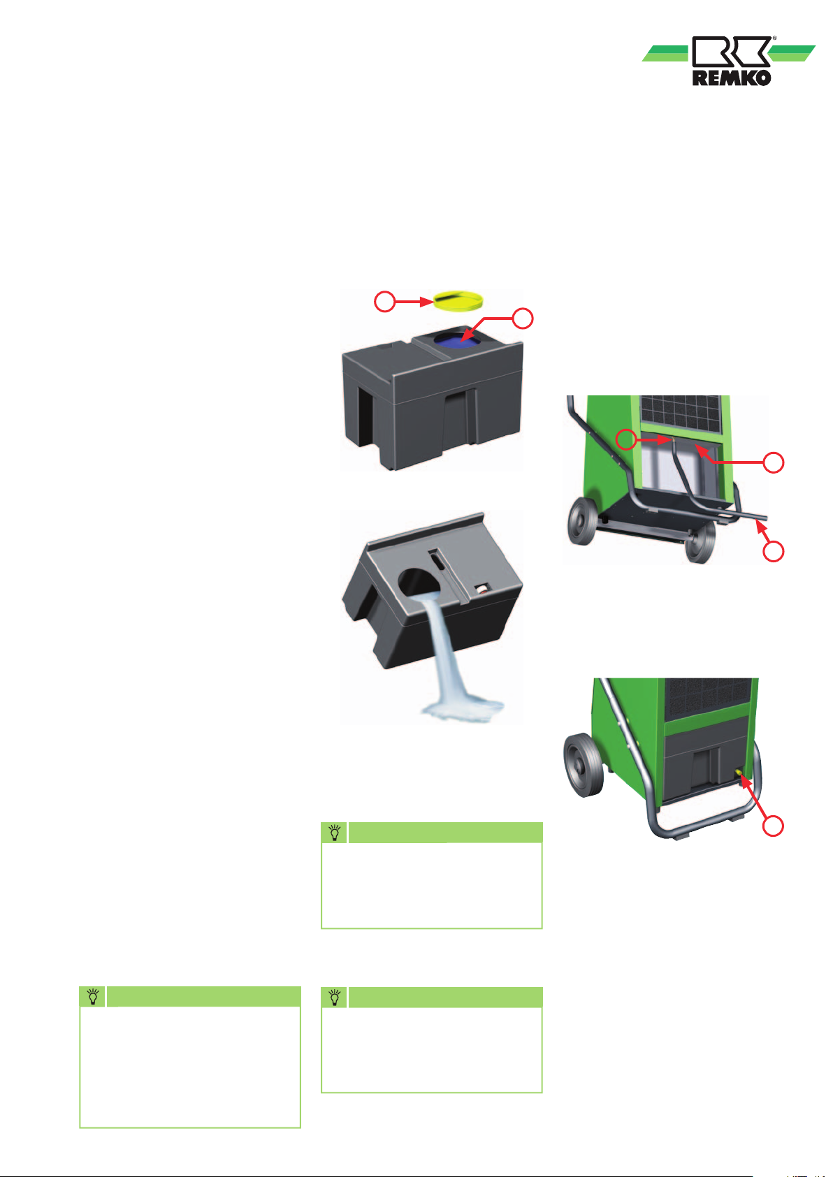
3. Place the container carefully
outside the unit and open
the sealing cover [F] of
the pouring opening [E].
F
4. Pour the water into a drain.
Unit operation with
hose connection
The condensate traps [K]
of the AMT 65 and 85-E
are equipped with a ½"
connection nozzle [A].
After removing the condensate
E
container, a standard ½" water
hose [S] may be connected to this.
The hose [S] is not provided from
the factory.
A
K
S
In the AMT 45-E, the hose is
connected directly to the ½"
connection nozzle [D] of
the condensate container.
To empty the condensate
container, the following procedure
must be followed:
1. Move the operating switch [2]
to the "0" (off) position.
Otherwise, the AMT 65-E and
AMT 85-E units would restart
immediately after the container
is removed.
2. Remove the condensate
container.
To do this, lift the container
slightly using the embedded
recessed grip and then pull it
carefully forwards and out.
NOTE
Beware of dripping
condensate.
After switching off the units,
the evaporator may continue
to defrost under the influence
of the ambient temperature.
5. Close the pouring opening
[E] and carefully insert
the condensate container back
into the unit.
NOTE
After being emptied,
the condensate container
incl. float must be checked
for damage, contamination etc.
6. Switch the unit back on using
the operating switch [2].
NOTE
The AMT 45-E units are
only fully functional if
the condensate container is
inserted properly.
D
To operate the units,
the condensate container must
always be inserted correctly
in the AMT 45-E.
In unattended permanent
operating mode, the condensate
should preferably be drained
into a lower-level flow.
If using a collection container (pan,
bucket, etc.), the unit must be
placed at a correct height.
For further suggestions, see
the next page!
11
Page 12
REMKO AMT
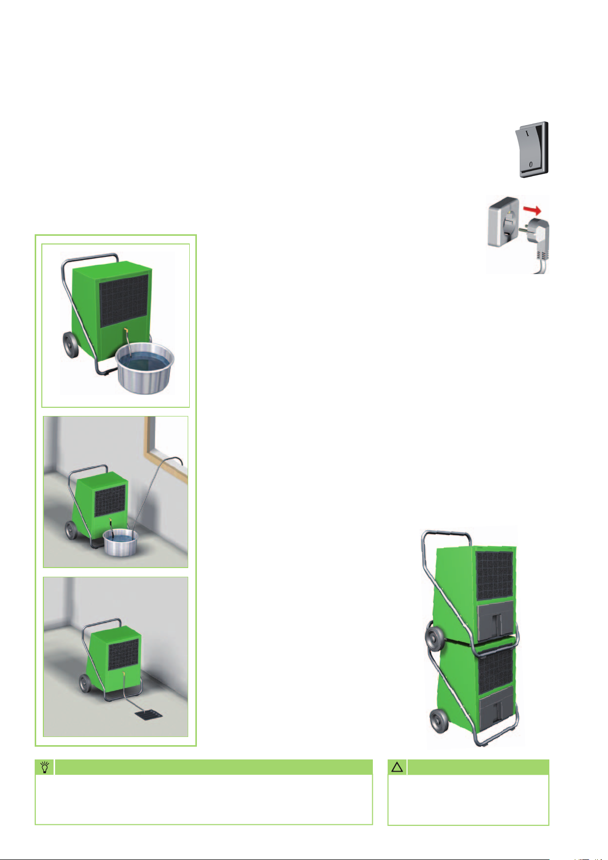
AMT 115-E condensate drain
Due to their high dehumidification capacity, the AMT 115-E units are not
equipped with an internal condensate container.
The condensate drainage is to be provided by the customer in suitable
containers via the exterior unit connection nozzles (½").
The following variants (for example) are available to drain the condensate
water that arises:
Variant A
The water is collected
in a container that is provided
by the customer and that is
of sufficient size.
The container must be checked
regularly and emptied if necessary.
There is no overflow protection!
Variant B
The water is first collected
in a container and fed into a higher
drain via a separate submerged
pump or drained outside directly.
This variant is suitable
for installation locations with
an insufficient incline or without
a drain.
Shutdown
Move the operating switch
to the "0" (off) position.
If the units are inactive for longer
periods, disconnect them from
the mains power supply.
Empty the condensate container
and dry with a clean cloth.
Beware of dripping condensate!
When storing the unit, cover
with a plastic sheet/foil if
necessary and store in an upright
position in a sheltered and dry
location.
To save space when storing,
the units can be stacked on top of
one another.
For this purpose, they are
equipped with rubber pads
on the base plate.
Variant C
The water is fed into a lower
drain via a ½“ hose pipe.
This variant enables unattended
permanent operating mode.
NOTE
These variants can also be used in the same way for continual
condensate drainage for all other unit types.
12
!
ATTENTION
The units must be protected
against falling down and unauthorised access after stacking.
Page 13
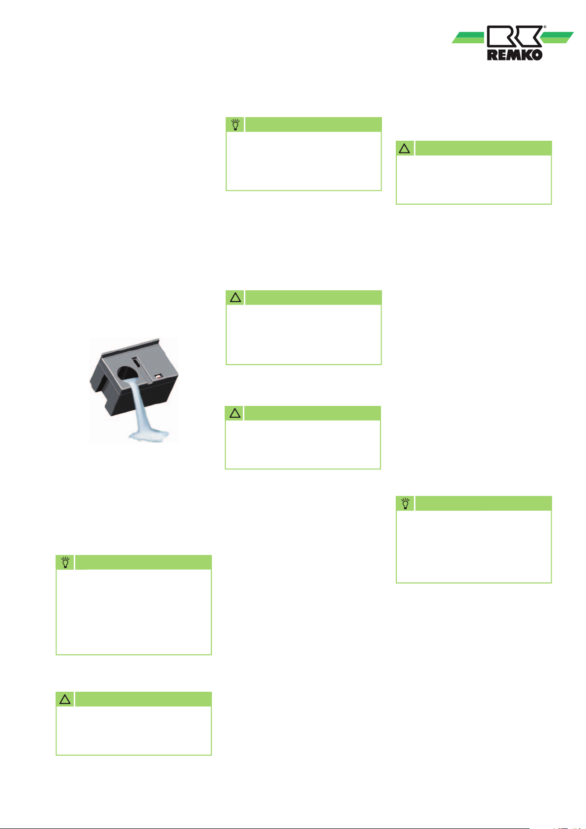
Transportation
Care and maintenance
For easy transportation, the units
are equipped with 2 large
wheels and an ergonomic
transportation and protective
clamp.
This can also be dismantled easily
if required.
When transporting the units,
observe the following:
1. Before each change of location,
switch off the unit and remove
the power plug from the mains
socket.
2. Drain the condensate container.
3. If moisture remains
on the evaporator or water
remains in the condensate
container, the units must only
be transported in an upright
position.
NOTE
Beware of dripping
condensate.
After switching off the units,
the evaporator may continue
to defrost under the influence
of the ambient temperature.
NOTE
Regular care and maintenance
is fundamental to a long
service life and fault-free
operation of the unit.
All moving parts have a lowmaintenance permanent coat of
lubricant. The refrigerant system is
designed as a hermetically sealed
system and may only be repaired
by a specialist.
!
ATTENTION
Before undertaking any work
on the units, the power
plug must be removed from
the mains socket.
■
Observe the regular care and
maintenance intervals
!
ATTENTION
Check the inlet and outlet grille for contamination on a regular basis.
■
In accordance with
the operating conditions,
the units must, if necessary,
be checked at least yearly by
a specialist to ensure that they
are in a condition that is safe
to use
■
Keep the units free of dust and
other debris
■
Only clean the units with a dry
or moistened cloth
■
Never subject to direct jets of
water.
e.g. pressure washers etc.
Cleaning the dust filter
!
ATTENTION
Check the inlet and outlet grille
and the dust filter for contamination on a regular basis.
Slide the protection grid upwards
slightly, then pull forwards and
remove downwards.
Then remove the dust filter which
has now been released.
Light contamination of the dust
filter may be remedied with careful
blowing or suction.
Heavier contamination may be
remedied by rinsing the filter
in a lukewarm (max. 40°C) soap
solution.
Finally, always rinse the filter
carefully with clear water and
allow to dry!
Before refitting the dust filter,
ensure that its fully dry and that no
damage has been sustained.
NOTE
Heavily contaminated dust
filters must be replaced with
new parts.
Only original replacement
parts may be used.
The units may only be operated
with the dust filter in place.
!
ATTENTION
The mains cable must never
be used as a pull cord or fixing
device.
■
Never use abrasive or solvent-
based cleaners
■
Use only suitable cleaners
for heavy contamination
13
Page 14
REMKO AMT
Cleaning the units
The unit housing must be opened
to allow the inside of the unit to be
cleaned and to provide access
to electrical components.
NOTE
Adjustment and maintenance
work may only be carried
out by authorised qualified
technicians.
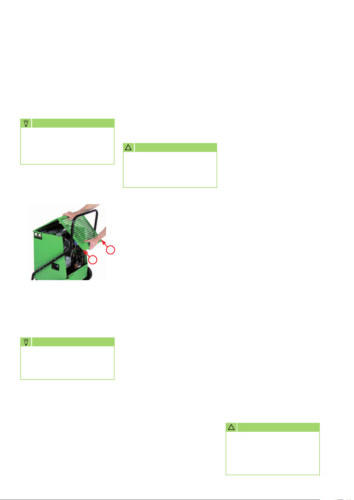
1. Remove the 2 fastening screws
[B].
2. Lift the housing part and
unhinge the front flaps.
B
B
3. Clean the condenser fins by
blowing, with suction or using
a smooth brush.
4. Clean the evaporator fins,
for example with a lukewarm
soap solution, or similar.
NOTE
When cleaning the exchanger,
particular care must be taken
because the fine aluminium
fins bend very easily.
5. Never subject to direct jets of
water.
6. Rinse with clean water
to remove any remaining soap.
7. Clean the internal surfaces of
the unit and the fan blade.
8. Clean the condensate trap and
the connection nozzles.
9. Once cleaning has been
completed, the unit should be
dried. Take particular care with
electrical components!
10. Re-install all dismantled
components in reverse order.
11. Carry out a unit function check
and electrical safety check.
!
ATTENTION
An electrical safety check must
be carried out in accordance
with VDE 0701 after any work
on the units.
Troubleshooting
The units are manufactured
using state-of-the-art
production methods and tested
several times to verify their correct
function. However, if a functional
fault should occur, the unit should
first be checked in accordance with
the following list.
The unit does not start
■
Check the setting of
the operating switch. The green
indicator light should illuminate
■
Check the power supply and
the power fuse provided by
the customer 230V/1~/50 Hz
■
Check the power plug and
the cable for damage
■
Check the level and correct
positioning of the condensate
container
(not AMT 115-E)
■
Check the setting of
the humidity switch
(accessories).
The pre-set value must be
lower than the relative humidity
in the room
■
Check the humidity switch
adapter for damage and correct
positioning
The red indicator light
(Malfunction) illuminates
■
The cooling cycle is overloaded
or overheated
■
Before starting the unit again,
first identify the cause of
the malfunction.
Note that the re-start is
automatic after the cooling
process is complete!
The unit runs but does not
form any condensate
■
Check the room temperature
The operating range of the unit
is between 3°C and 32°C
■
Check the humidity of the air,
min. 40% RH required
■
Check the dust filter
for contamination and clean or
replace if necessary
■
Check the evaporator
and condenser fins
for contamination and clean if
necessary
■
Check the evaporator for ice or
rime formation.
If ice has formed, check
the functionality of
the automatic defrost and
the temperature sensor
■
If the unit fails
to function correctly after
the checks have been carried
out, an authorised specialist
!
ATTENTION
Work on the refrigerant
system and on the electrical
equipment must only be
conducted by a speciallyauthorised specialist!
14
Page 15
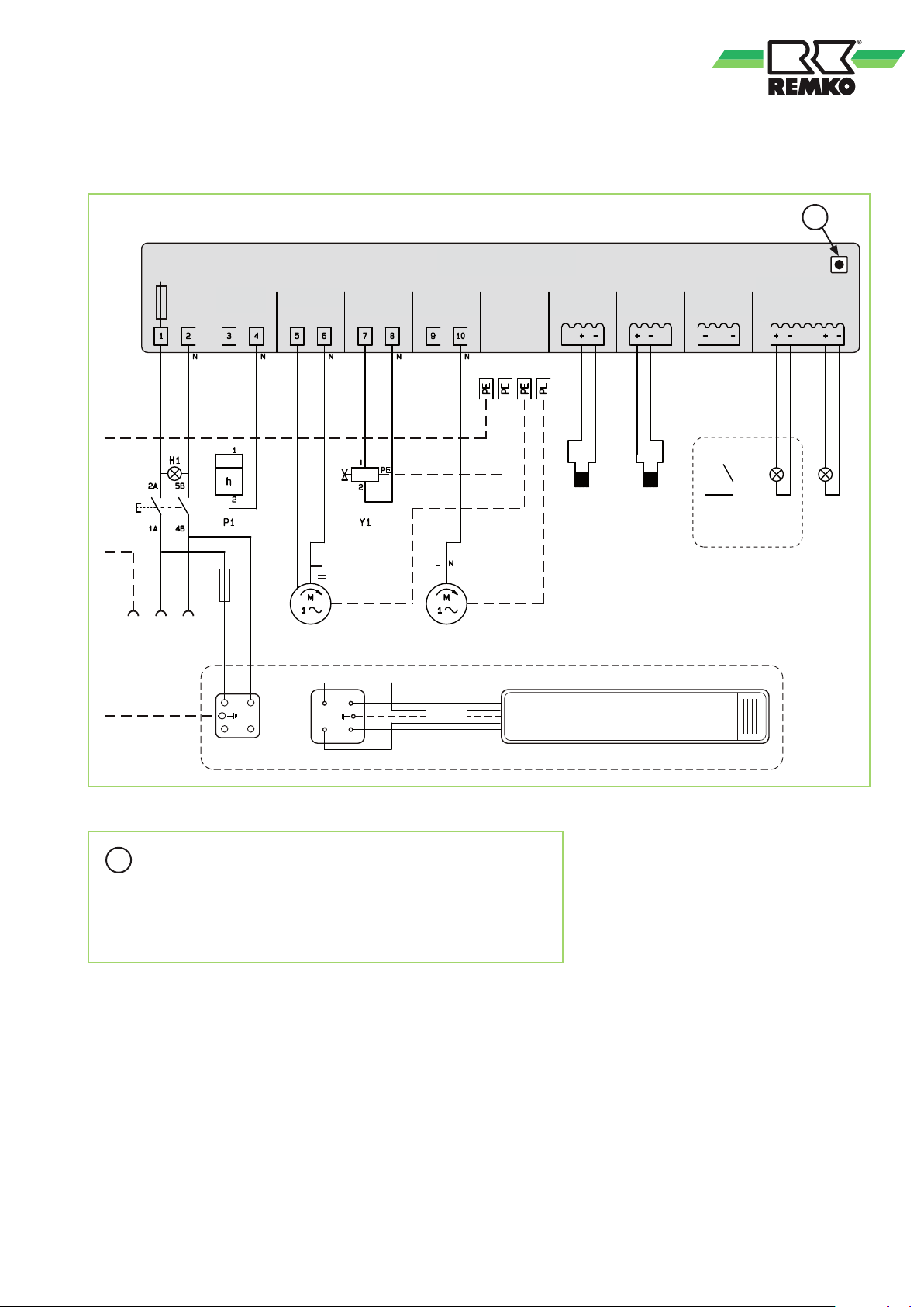
Electrical wiring diagram
AMT 45-E to 115-E
3,15 A
Operating
stunden
hours
1,0 A
F
S1
PE
L NPE
230V/1~/50Hz
Control board
Steuerplatine
Compressor Changeover
KompressorBetriebs-
C R
M1 M2
Kompressor Ventilatormotor
Compressor Fan motor
C1
S
Umschalt-
ventil
valve
PE
Ambiente
Umluft-
ventilator
air fan
D
Lamp
Fühler °C
Probe °C
Verdampfer Kondensator
evaporator
PE
NTC NTC
PE
Fühler °C
Probe °C
condenser
Fühler
Probe °C
Wasser Stop
water stop
Not applicable
entfällt bei AMT 115-E
for AMT 115-E
Lampe
Wasser
H2 H3
Yellow Red
GelbSW
water
stop
Stop
Lampe
Fail
Störung
lamp
Rot
WHITE
WEISS
BLACK
1
2
3
4
Socket
Steckdose
am Gerät
on the unit
Plug
Stecker
2
3
VIOLET
VIOLETT
1
4
SCHWARZ
VIOLETT
VIOLET
Kondensatpumpe (optional)
Condensate pump (optional)
= Test button
D
The test button is only provided for maintenance and checking
tasks carried out by the service personnel.
When it is pressed, the defrosting timer settings are reduced.
not possible for AMT 115-E
We reserve the right to modify the dimensions and design as part of the ongoing technical development process.
15
Page 16
REMKO AMT
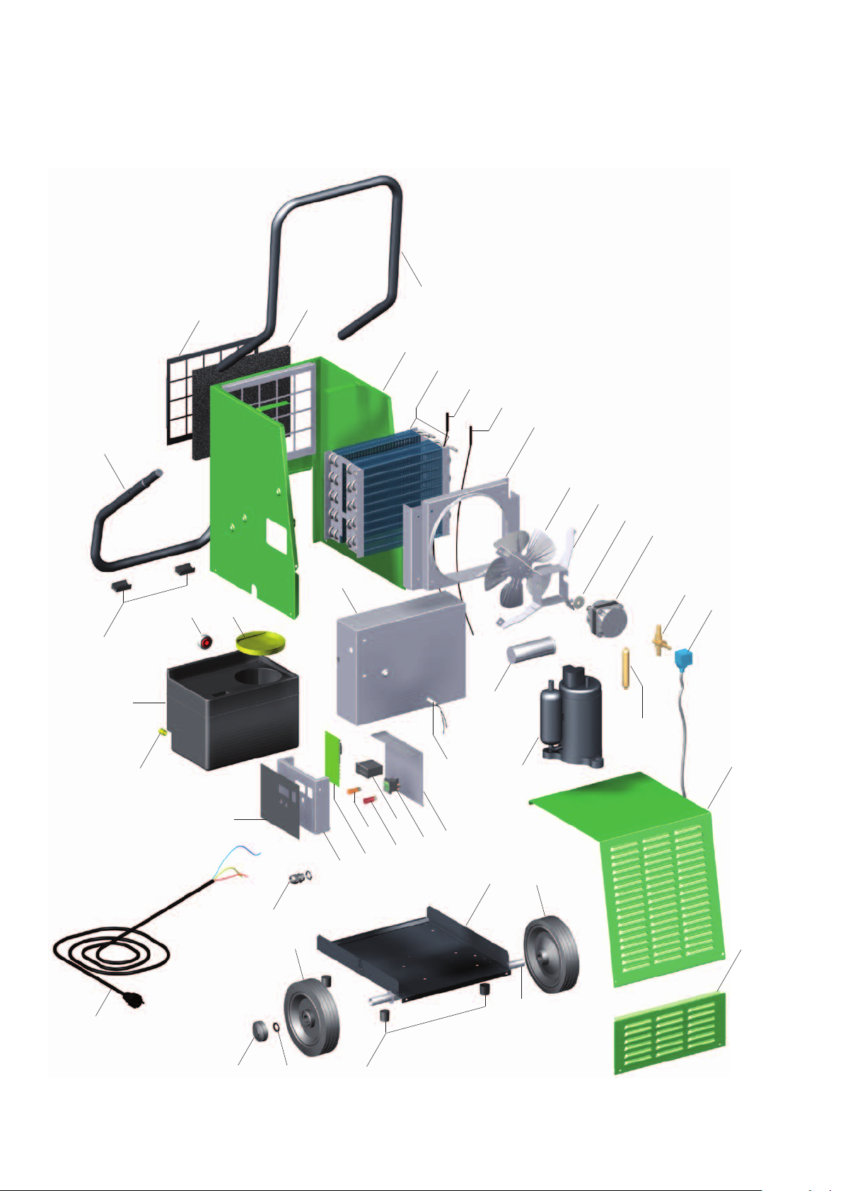
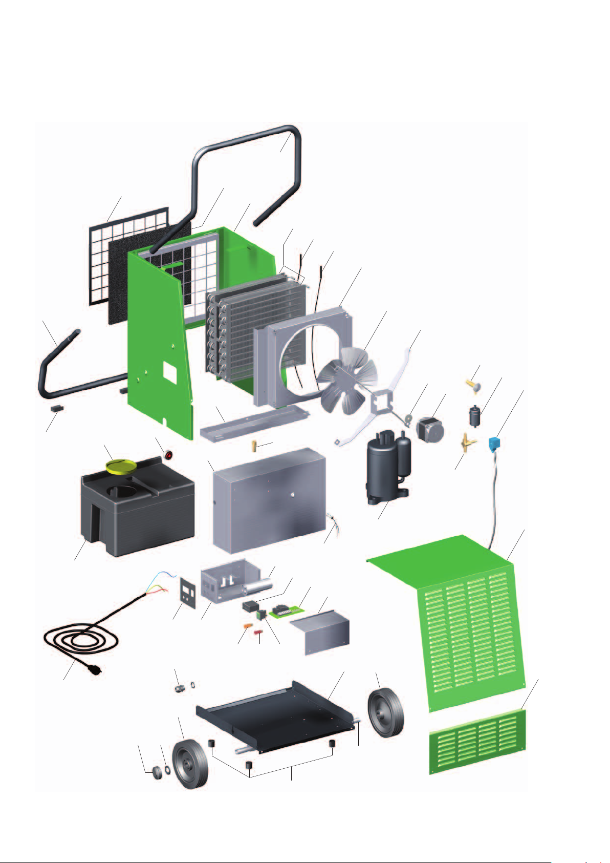
Exploded view of the AMT 45-E unit
50
49
48
1
4546
2
40
3
4
5
6
7
8
10
11
12
13
14
15
18
30
47
31
26 27
29
25
32
33
24
34
36
35
37
39
38
16
20
17
22 25
21
23
16
We reserve the right to modify the dimensions and design as part of the ongoing technical development process.
Page 17
Spare parts list AMT 45-E
No. Description EDP no.
1 Air-inlet grille 1105601
2 Dust filter 1105602
3 Transportation bracket 1105603
4 Fixed base cpl. 1105604
5 Evaporator fin package cpl. 1105905
6 NTC evaporator probe 1105606
7 NTC condenser probe 1105607
8 Fan housing 1105608
10 Fan blade 1105609
11 Engine mounting cpl. 1105610
12 Drive clutch 1108455
13 Fan motor 1108077
14 Solenoid valve 1105715
15 Coil for solenoid valve 1105714
16 Dry filter 1105908
17 Compressor, cpl. 1105909
18 Operating condenser 1105910
20 Inspection housing part cpl. 1105618
21 Completion panel 1105619
22 Base plate 1105956
23 Axle 1105621
24 Base plate rubber stop (set) 1105622
25 Wheel 1102155
26 Hubcap 1101623
27 Locking ring 1101622
29 Strain relief 1101267
30 Mains cable with plug 1105624
31 Insulation 1105625
32 Switch cabinet housing 1105911
33 Control board cpl. 1105913
34 Indicator light, yellow 1105611
35 Indicator light, red 1105612
36 Operating hours counter 1105515
37 Operating switch with indicator light 1105628
38 Housing cover 1105912
39 Water stop probe 1105723
40 Support frame 1105914
45 Container seal 1105632
46 Magnetic float 1105633
47 Sealing cap 1105634
48 Condensate container cpl. 1105635
49 Stand rubber stop (set) 1105636
50 Stand 1105637
When ordering replacement parts, please always state the EDP no. and unit number (see name plate)!
17
Page 18
REMKO AMT
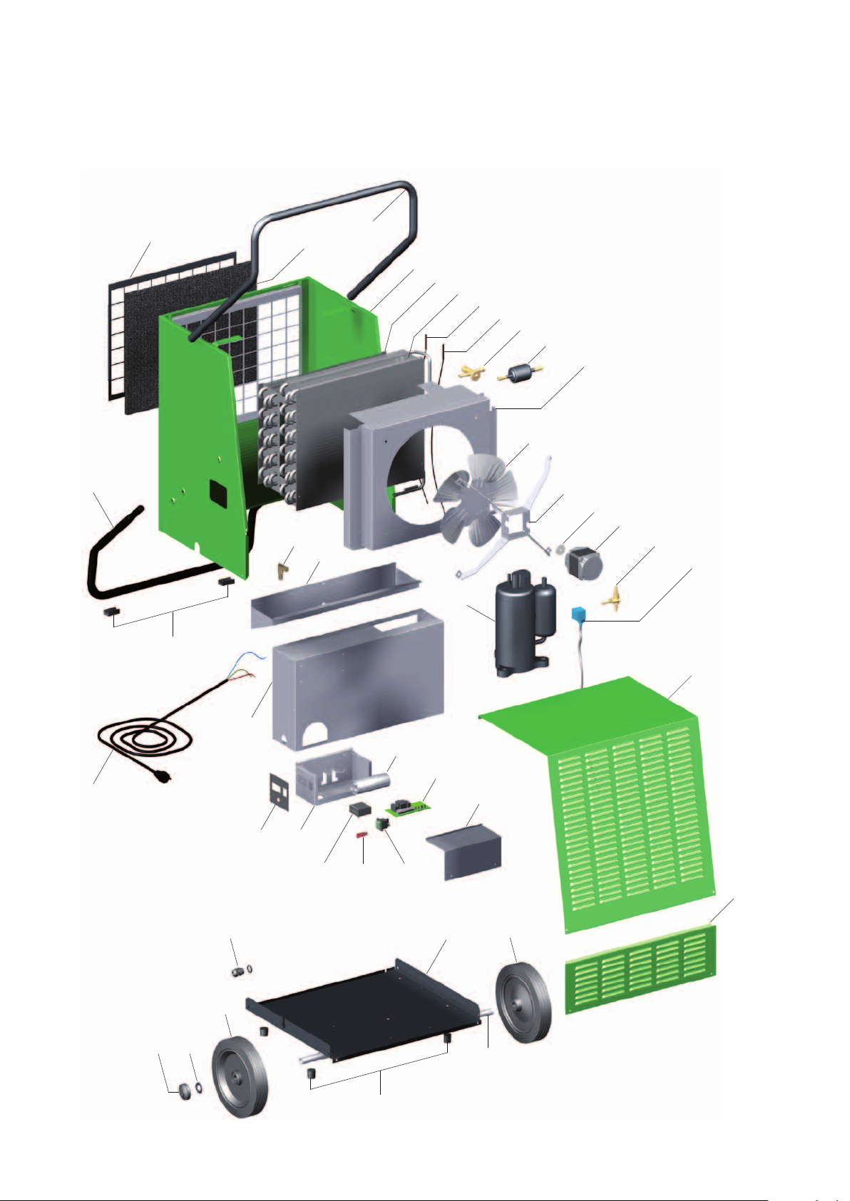
Exploded view of the AMT 65-E and 85-E units
4
52
51
49
45
47
2
3
5
6
7
8
10
11
14
12
13
46
15
16
1
48
30
50
17
18
39
32
31
35
29
25
2726
3433
40
38
37
36
22 25
23
20
21
18
24
We reserve the right to modify the dimensions and design as part of the ongoing technical development process.
Page 19
Spare parts list for the AMT 65-E and 85-E units
No. Description AMT 65-E AMT 85-E
EDP no. EDP no.
1 Air-inlet grille 1105659 1105659
2 Dust filter 1105660 1105660
3 Fixed base cpl. 1105661 1105661
4 Transportation bracket 1105662 1105662
5 Evaporator fin package cpl. 1105711 1105731
6 NTC evaporator probe 1105606 1105606
7 NTC condenser probe 1105607 1105607
8 Fan housing 1105712 1105712
10 Fan blade 1105665 1105665
11 Engine mounting cpl. 1105666 1105666
12 Drive clutch 1101155 1101155
13 Fan motor 1105667 1105667
14 Temperature valve ---------- 1105732
15 Dry filter 1105713 1105733
16 Coil for solenoid valve 1105714 1105714
17 Solenoid valve 1105715 1105715
18 Compressor cpl. 1105716 1105734
20 Inspection housing part cpl. 1105671 1105671
21 Completion panel 1105647 1105647
22 Base plate 1105957 1105957
23 Axle 1105673 1105673
24 Base plate rubber stop (set) 1105622 1105622
25 Wheel 1102155 1102155
26 Hubcap 1101623 1101623
27 Locking ring 1101622 1101622
29 Strain relief 1101267 1101267
30 Mains cable with plug 1105624 1105624
31 Insulation 1105651 1105651
32 Switch cabinet housing 1105717 1105717
33 Indicator light, yellow 1105611 1105611
34 Indicator light, red 1105612 1105612
35 Operating switch with indicator light 1105628 1105628
36 Housing cover 1105718 1105718
37 Control board cpl. 1105719 1105719
38 Operating hours counter 1105515 1105515
39 Operating condenser 1105720 1105735
40 Water stop probe 1105723 1105723
45 Support frame 1105721 1105721
46 Hose connection nozzles ½" 1105567 1105567
47 Condensate trap 1105722 1105722
48 Magnetic float 1105633 1105633
49 Container seal 1105632 1105632
50 Condensate container cpl. 1105657 1105657
51 Stand rubber stop (set) 1105636 1105636
52 Stand 1105676 1105676
When ordering replacement parts, please always state the EDP no. and unit number (see name plate)!
19
Page 20
REMKO AMT
Exploded view of the AMT 115-E unit
49
1
2
47
46
3
4
5
6
7
8
9
10
11
15
16
17
18
19
20
22
36
30
48
31
29
35
45
37
38
24
44
43
42
4039
41
25
26 29
27
20
28
We reserve the right to modify the dimensions and design as part of the ongoing technical development process.
Page 21
Spare parts list AMT 115-E
No. Description EDP no.
1 Air-inlet grille 1105677
2 Dust filter 1105678
3 Transportation bracket 1105679
4 Fixed base cpl. 1105680
5 Fin evaporator 1105740
6 Fin condenser 1105741
7 NTC evaporator probe 1105606
8 NTC condenser probe 1105607
9 Temperature valve 1105742
10 Dry filter 1105743
11 Fan housing 1105950
15 Fan blade 1105686
16 Engine mounting cpl. 1105687
17 Drive clutch 1101155
18 Fan motor 1105555
19 Solenoid valve 1105715
20 Coil for solenoid valve 1105714
22 Compressor, cpl. 1105746
24 Inspection housing part cpl. 1105689
25 Completion panel 1105690
26 Base plate 1105951
27 Axle 1105692
28 Base plate rubber stop (set) 1105622
29 Wheel 1101621
30 Hubcap 1101623
31 Locking ring 1101622
35 Strain relief 1101267
36 Mains cable with plug 1105624
37 Insulation 1105693
38 Switch cabinet housing 1105952
39 Operating hours counter 1105515
40 Indicator light, red 1105612
41 Operating switch with indicator light 1105628
42 Housing cover 1105953
43 Control board cpl. 1105719
44 Operating condenser 1105954
45 Support frame 1105955
46 Condensate trap 1105697
47 Hose connection nozzles ½" 1105698
48 Stand rubber stop (set) 1105636
49 Stand 1105699
When ordering replacement parts, please always state the EDP no. and unit number (see name plate)!
21
Page 22

REMKO AMT
Maintenance protocol
Unit type: .................................. Unit number: ...................................
1 2 3 4 5 6 7 8 9 10 11 12 13 14 15 16 17 18 19 20
Unit cleaned - outside -
Unit cleaned - inside -
Fan blade cleaned
Fan housing cleaned
Condenser cleaned
Evaporator cleaned
Fan function checked
Air-inlet grid with filter cleaned
Unit checked for damage
Safety devices checked
All fastening screws checked
Electrical safety check
Test run
✍
Comments: .....................................................................................................................................................
.............................................................................................................................................................................
.............................................................................................................................................................................
1. Date: ..............
..............................
Signature
6. Date: ..............
..............................
Signature
11. Date: ............
..............................
Signature
16. Date: ............
..............................
Signature
2. Date: ..............
..............................
Signature
7. Date: ..............
..............................
Signature
12. Date: ............
..............................
Signature
17. Date: ............
..............................
Signature
3. Date: ..............
..............................
Signature
8. Date: ..............
..............................
Signature
13. Date: ............
..............................
Signature
18. Date: ............
..............................
Signature
4. Date: ..............
..............................
Signature
9. Date: ..............
..............................
Signature
14. Date: ............
..............................
Signature
19. Date: ............
..............................
Signature
5. Date: ..............
..............................
Signature
10. Date: ............
..............................
Signature
15. Date: ............
..............................
Signature
20. Date: ............
..............................
Signature
22
Unit to be maintained only by authorised specialists in accordance with the statutory regulations.
Page 23
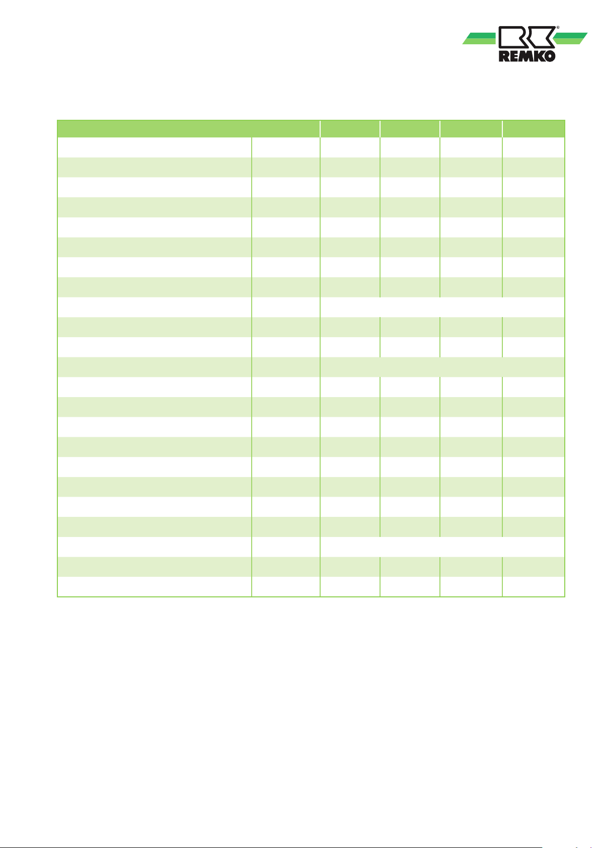
Technical data
Series AMT 45-E AMT 65-E AMT 85-E AMT 115-E
Operating range, temperature °C 3-32 3-32 3-32 3-32
Operating range, humidity % RH 40-100 40-100 40-100 40-100
Dehumidification capacity max. l/day 42 64 80 119
at 30°C/80% RH
at 20°C/70% RH
at 10°C/60% RH
l/day (DER) 37.4 (2.32) 56.8 (2.96) 70.8 (3.07) 106.4 (3.47)
l/day (DER) 21.2 (1.73) 31.7 (2.06) 40.1 (2.26) 60.7 (2.57)
l/day (DER) 6.9 (0.78) 9.4 (0.93) 13.2 (0.89) 18.0 (1.01)
Max. airflow volume m3/h 280 590 650 970
Condensate container capacity Litres 8/7 18/15 18/15 without
Compressor / condenser Configuration Rotary piston
Refrigerant
1)
R410A R410A R410A R410A
Refrigerant quantity g 480 580 750 1270
Power supply V/Hz 230/1~/50
Max. rated current consumption A 3.2 4.0 4.8 6.7
Max. power consumption kW 0.730 0.890 1.020 1.385
at 20°C/70% RH kW 0.510 0.640 0.740 0.986
Customer-provided electrical protection A 16 16 16 16
Sound pressure level LpA 1m
2)
dB (A) 58 60 63 67
Depth mm 490 530 530 605
Width mm 480 615 615 710
Height mm 640 795 795 895
Height incl. transportation bracket mm 950
Weight kg 34 45.5 49.5 65
EDP no. 617400 617550 617800 617900
(DER) = Dehumidification output figure in accordance with DIn EN 810
1)
Contains greenhouse gas according to Kyoto protocol
2)
Noise level measurement DIn 45635 - 13 - KL 3
We reserve the right to modify the dimensions and design as part of the ongoing technical development process.
23
Page 24
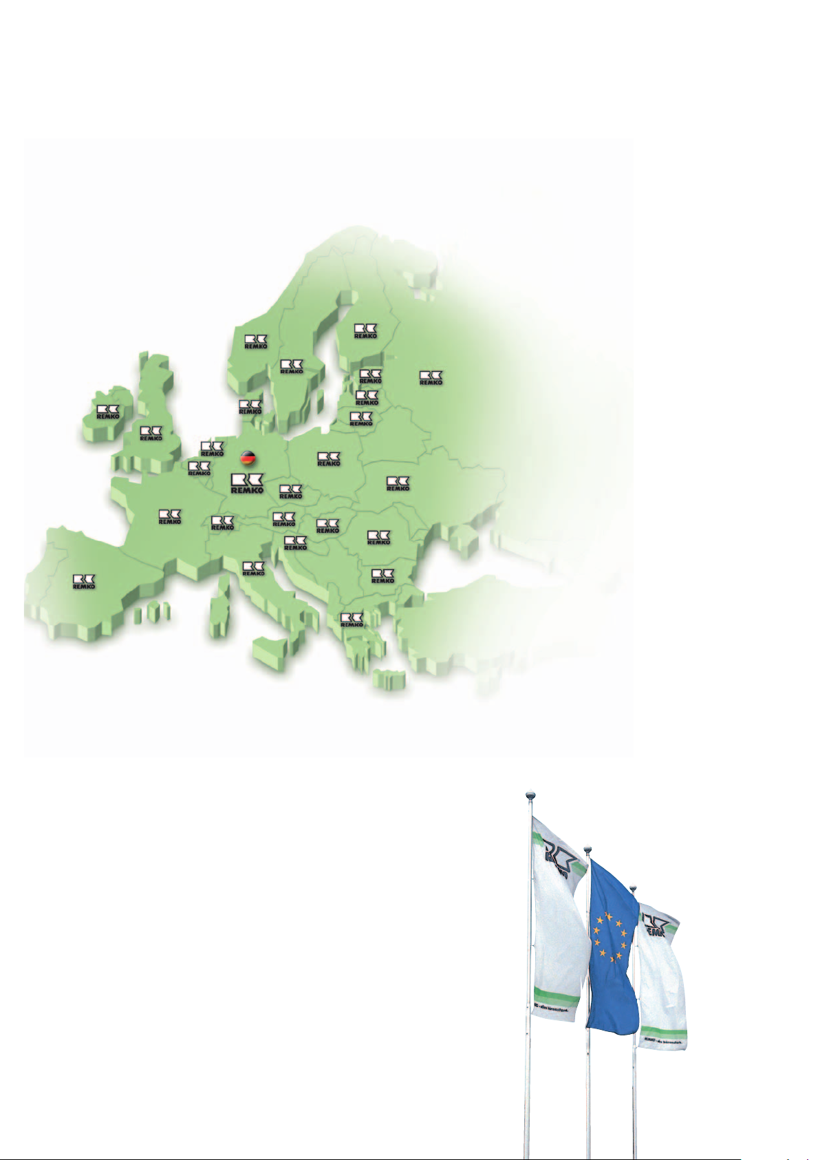
REMKO INTERNATIONAL
... and also right in your neighbourhood!
Take advantage of our experience and advice
REMKO GmbH & Co. KG
Klima- und Wärmetechnik
Im Seelenkamp 12 D-32791 Lage
Postfach 1827 D-32777 Lage
Telephone +49 5232 606-0
Fax +49 5232 606-260
E-mail [email protected]
Internet www.remko.de
Consulting
Thanks to intensive training,
our consultants are always
completely up-to-date when
it comes to technical expertise.
This has given us the reputation of
being more than just an excellent,
reliable supplier:
REMKO, a partner who helps
to solve problems.
Sales
REMKO offers not just a well-
established sales network both
nationally and internationally,
but also has exceptionally highly-
qualified sales specialists.
REMKO employees in the field
are more than mere salespeople:
above all, they must be
advisers to our customers
in air conditioning and heating
technology.
Customer service
Our units operate precisely and
reliably. However, in the event
of a malfunction REMKO customer
service is quickly on the scene.
Our comprehensive network
of experienced dealers guarantees
quick and reliable service.
We reserve the right to make technical changes and provide no warranty as to the accuracy of this data!
 Loading...