

Page 1
IMI CORNELIUS INC g One Cornelius Place g Anoka, MN 55303-6234
Telephone (800) 238-3600 Facsimile (612) 422-3246
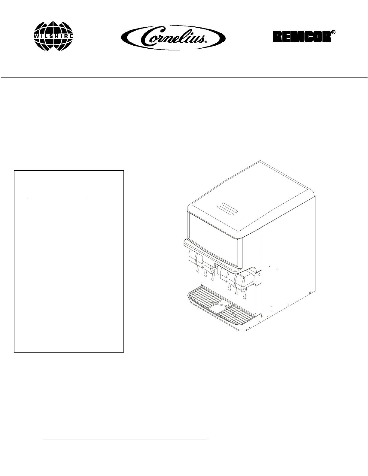
ICE/BEVERAGE DISPENSER
MODEL: TRIAD--150
Installation Manual
IMPORTANT:
TO THE INSTALLER.
It is the responsibility of
the Installer to ensure that
the water supply to the
dispensing equipment is
provided with protection
against backflow by an air
gap as defined in
ANSI/ASME A112.1.2-1979;
or an approved vacuum
breaker or other such
method as proved effective
by test.
Water pipe connections
and fixtures directly
connected to a potable
water supply shall be
sized, installed, and
maintained according to
Federal, State, and Local
Codes.
Part No. 620911102
October, 1998
Revised; January 9, 2002
Revision D
THIS DOCUMENT CONTAINS IMPORTANT INFORMA
This Manual must be read and understood before installing or operating this equipment
TION
IMI CORNELIUS INC; 1998-2002Ó
PRINTED IN U.S.A
Page 2

TABLE OF CONTENTS
SAFETY PRECAUTIONS 1...................................................
DESCRIPTION 1........................................................
SPECIFICATIONS 1.....................................................
INSTALLA TION INSTRUCTIONS 2............................................
KIT 02394 3...........................................................
GATE RESTRICTOR PLATE 4............................................
ADJUSTMENT 4........................................................
TROUBLESHOOTING 7......................................................
BLOWN FUSE OR CIRCUIT BREAKER. 7..................................
GATE DOES NOT OPEN. AGITAT OR DOES NOT TURN. 7..................
GATE DOES NOT OPEN OR IS SLUGGISH. AGITATOR TURNS. 7..........
ICE DISPENSES CONTINUOUSLY. 7......................................
SLUSHY ICE. WATER IN HOPPER. 7.....................................
BEVERAGES DO NOT DISPENSE. 7......................................
BEVERAGES TOO SWEET. 7............................................
BEVERAGE NOT SWEET ENOUGH. 8....................................
BEVERAGES NOT COLD (UNITS WITH BUILT-IN COLD PLATE). 8...........
WARRANTY 10..............................................................
Page
LIST OF FIGURES
FIGURE 1. ICE DIVERTER KIT 3..........................................
FIGURE 2. GATE RESTRICTOR PLATE 4..................................
FIGURE 3. MOUNTING TEMPLATE 5.....................................
FIGURE 4. WIRING DIAGRAM BEV/CP DISPENSER 9......................
Rev B
June, 1998
i
620911102
Page 3
SAFETY PRECAUTIONS
This ice dispenser has been specifically designed to provide protection against personal injury and eliminates
contamination of ice. To ensure continued protection and sanitation, observe the following:
ALWAYS: disconnect power to the dispenser before servicing or cleaning.
NEVER: place hands inside of hopper or gate area without disconnecting power to the dispenser.
Agitator rotation occurs automatically when dispenser is energized!
ALWAYS: be sure the removable lid is properly installed to prevent unauthorized access to the hopper interior
and possible contamination of the ice.
ALWAYS: be sure the upper and lower front panels are securely fastened.
ALWAYS: keep area around the dispenser clean of ice cubes.
CAUTION: Dispenser cannot be used with crushed or flaked ice.
Use of bagged ice, which has frozen into large chun ks, can void warranty.
The dispenser agitator is not designed to be an ice crusher. Use of large
chunks of ice which “jam up” inside the hopper will cause failure of the agitator
motor and damage to the hopper. If bagged ice is used, it must be carefully and
completely broken into small, cu be-sized pieces before filling into the dispenser
hopper.
DESCRIPTION
The “ENDURO” series of ice dispensers solves your ice and beverage service needs in a sanitary, space saving,
economical way. Designed to be manually filled with ice from any remote ice-making source or top-mount ice
maker, these dispensers will dispense cubes (up to 1-1/4” in size), cubelets and hard-chipped or cracked ice;
and, in addition, several flavors of post-mix beverages. “BC” units include beverage faucets and a cold plate and
are designed to be supplied direct from syrup tanks and carbonator, with no additional cooling required.
IMPORTANT: For dispensing Scotsman “pellet” style ice (Model MH750 Ice makers), Kit Ice Diverter must be
installed on the dispenser. (See INSTALLATION INSTRUCTIONS on page 2).
SPECIFICATIONS
Model: TD150 (TRIAD-150)
Ice Storage: 150 lbs
Maximum Number of Faucets Available: 6 maximum
Built-in Cold Plate: Y es, on BC models only
Electrical: 120/1/60, Amps 3.0 total unit draw
Dimensions:
22I Wide X 30I Deep X 35-5/8I High
1
620911102June, 1998
Page 4

INSTALLATION INSTRUCTIONS
IMPORTANT: TO THE INSTALLER.
It is the responsibility of the Installer to ensure that the water supply to the dispensing equipment is
provided with protection against backflow by an air gap as defined in ANSI/ASME A112. 1.2-1979; or an
approved vacuum breaker or other such method as proved effective by test.
Water pipe connections and fixtures directly connected to a potable water supply shall be sized,
installed, and maintained according to Federal, State, and Local laws.
1. Locate the dispenser indoors on a level counter top.
A. LEG OPTION
Unpack the four (4) legs and install them into the threaded holes provided in the bottom of the unit.
The installer must provide flexibility in the product and utility supply to permit shifting the position of the
dispenser sufficiently to clean the area beneath it.
NOTE: Before installing legs, the plastic plugs must be removed.
B. COUNTER MOUNTING
The ice dispenser must be sealed to the counter. The template drawing indicates where openings can
be cut in the counter . Locate the desired position for the dispenser, then mark the outline dimensions
on the counter using the template drawings. Cut openings in counter.
Apply a continuous bead of NSF International (NSF) silastic sealant (Dow 732 or equal) approximately
1/4” inside of the unit outline dimensions and around all openings. Then, position the unit on the counter within the outline dimensions. All excess sealant must be wiped away immediately.
2. The beverage tubes, drain tube and power cord are routed through the large opening in the bottom of the
unit. See the MOUNTING TEMPLATE page NO TAG, for locating the required clearance hole in the counter
for these utility lines.
3. SINK DRAIN ASSEMBLY: Connect the drain tube to an open drain. Additional drain tubing is provided with
the unit. The drain tube must continuously pitch downward and contain no “traps” or improper drainage will
result.
A. Use tube, clamp and insulation provided to assemble drain.
B. T o assure proper drainage, do not allow ”trap” to form in drain line. Be sure drain line runs flat with
bottom of dispenser .
NOTE: This equipment must be installed with adequate backflow protection to comply with federal,
state, and local codes.
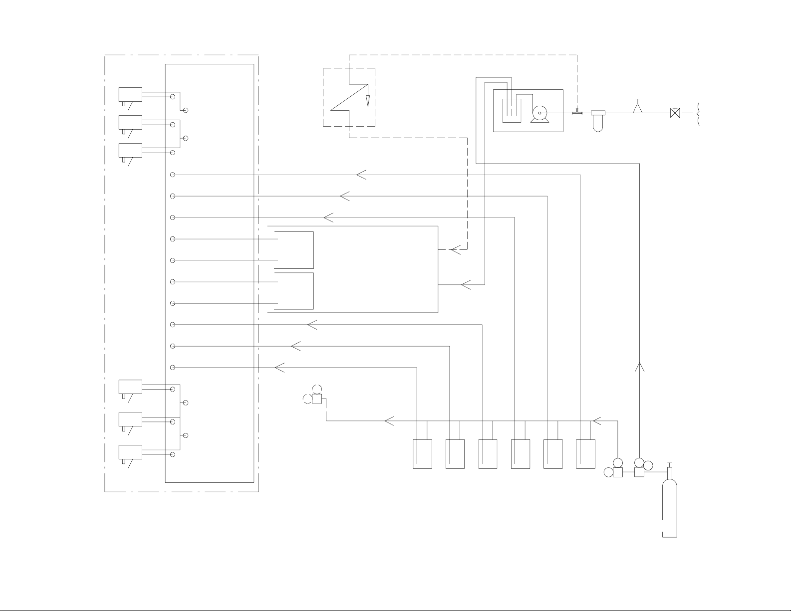
4. Connect the beverage system product tubes as indicated in the Beverage System Schematic. This work
should be done by a qualified service person.
NOTE: See Plumbing Schematic on page NO TAG of Manual or Decal on Splash Panel of the unit for the
location of syrup and water connections.
5. Clean the hopper interior (see CLEANING INSTRUCTIONS in Owner’s Manual).
6. Connect the power cord to a 120 volt, 60 cycle, 3-wire grounded receptacle.
620911102 June, 1998
2
Page 5
KIT 02394
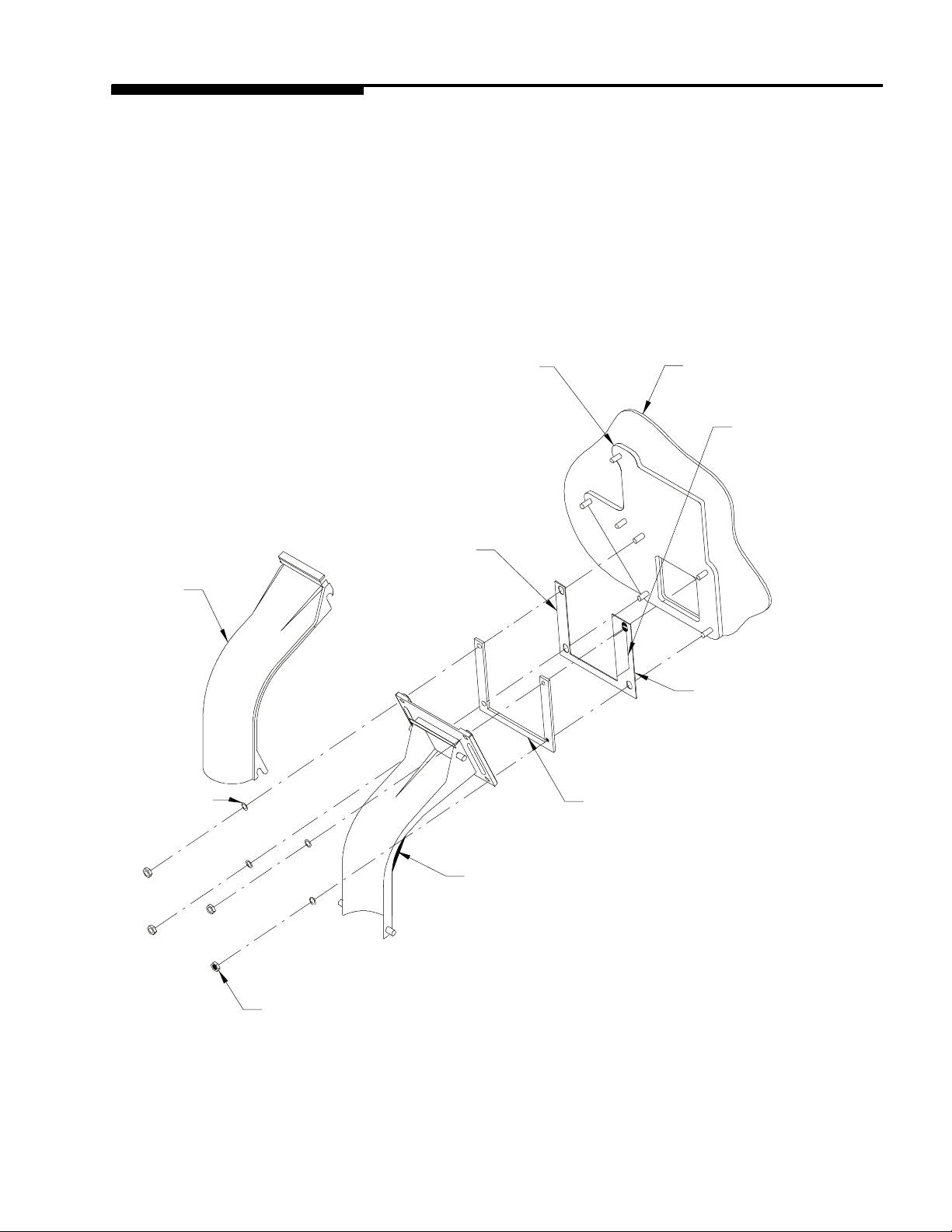
NOTE: For dispensing Scotsman MH 750 “nugget” style ice and Wilshire MCC550 and MCC700 compressed
ice cubes:
1. Disconnect power to dispenser.
2. Remove Merchandiser from dispenser.
3. Remove ice chute and discard gate restrictor.
4. Install ice diverter on gate mounting plate as shown below.
5. Apply RTV to back surface of ice diverter, to seal to gate mounting plate.
6. Reinstall gasket and ice chute.
7. Reinstall merchandiser and energize unit.
ICE CHUTE
COVER
10--32
WASHER
GATE MOUNTING PLATE
ICE DIVERTER
STORAGE
HOPPER
FLANGE EXTENDS
INTO STORAGE
HOPPER THROUGH
GATEOPENING
APPLY RTV TO
THIS SURFACE
TO SEAL TO
HOPPER GATE
MOUNTING
PLATE
GASKET
10--32 NUT
ICE CHUTE
FIGURE 1. ICE DIVERTER KIT
3
620911102June, 1998
Page 6
GATE RESTRICTOR PLATE
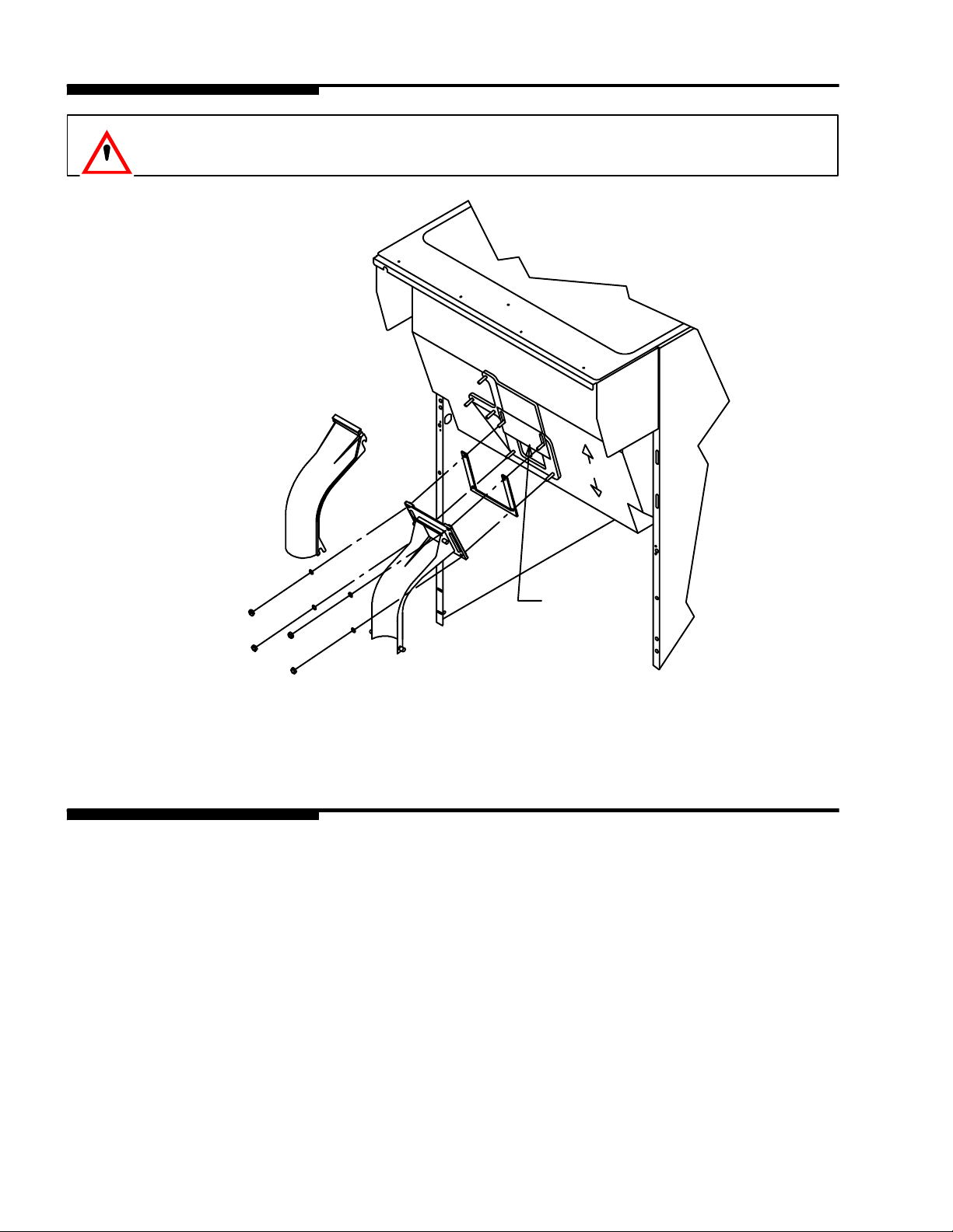
CAUTION: Disconnect power to dispenser before installing, removing or
adjusting restrictor.
ADJUSTMENT
INSTALL PLATE
ON STUDS AS
SHOWN
FIGURE 2. GATE RESTRICTOR PLATE
ADJUSTMENT
This plate may be adjusted as shown to reduce or increase the dispensing rate of ice, especially desirable when
using glasses or other containers with small openings. Adjustment can be made by sliding up or down with nuts
loosened, to obtain the desired amount of restriction.
620911102 June, 1998
4
Page 7
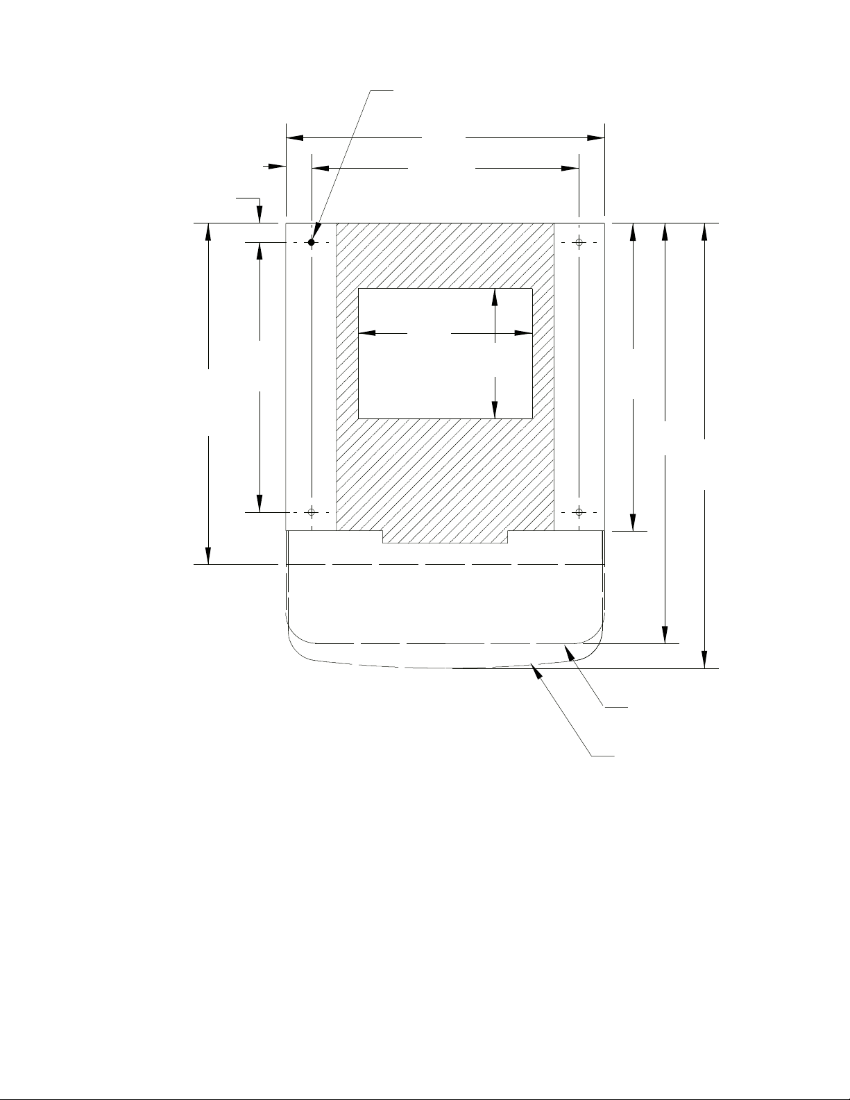
7/16 DIA.
22
23 9/16
ZMODEL
1 13/16
15/16
18 5/8
18 7/16
12
9
21 1/4
29
30 11/16
REMOVABLE SINK
RECOMMENDED COUNTER OPENING
SIZE 9 X 12 FOR UTILITIES AND BEVERAGE TUBEING. OPENING CAN BE
LOCATEDANYWHERE WITHIN THE
SHADED
FIGURE 3. MOUNTING TEMPLATE
TO FRONT OF DRIPTRAY
TO COUNTER TOP
TO FRONT TOP
OF DRIP TRAY
5
620911102June, 1998
Page 8
620911102
NON CARB WATER
CARB WATER
FAUCETS
VIEWED
FROM FRONT
6
6
6
W4
5
W3
4
S4
S5
S6
W4
W3
W2
W1
S1
S2
S3
3
W2
2
W1
1
CHECK VALVE
4,5,6
1,2,3
REQUIRED
REQUIRED
OPTIONAL FOR
DIET ORROOT
BEER (5-15 PSIG)
INSTALL FOR
NON CARB AS
REQUIRED
CARBONATOR
WATER
SUPPLY
FILTER
June, 1998
COLDPLATE
3+2+1 COLDPLATE
S3 S2 S1 S6 S5 S4
SYRUP TANKS
(15-50 PSIG)
CO2 TANKS
Page 9
TROUBLESHOOTING
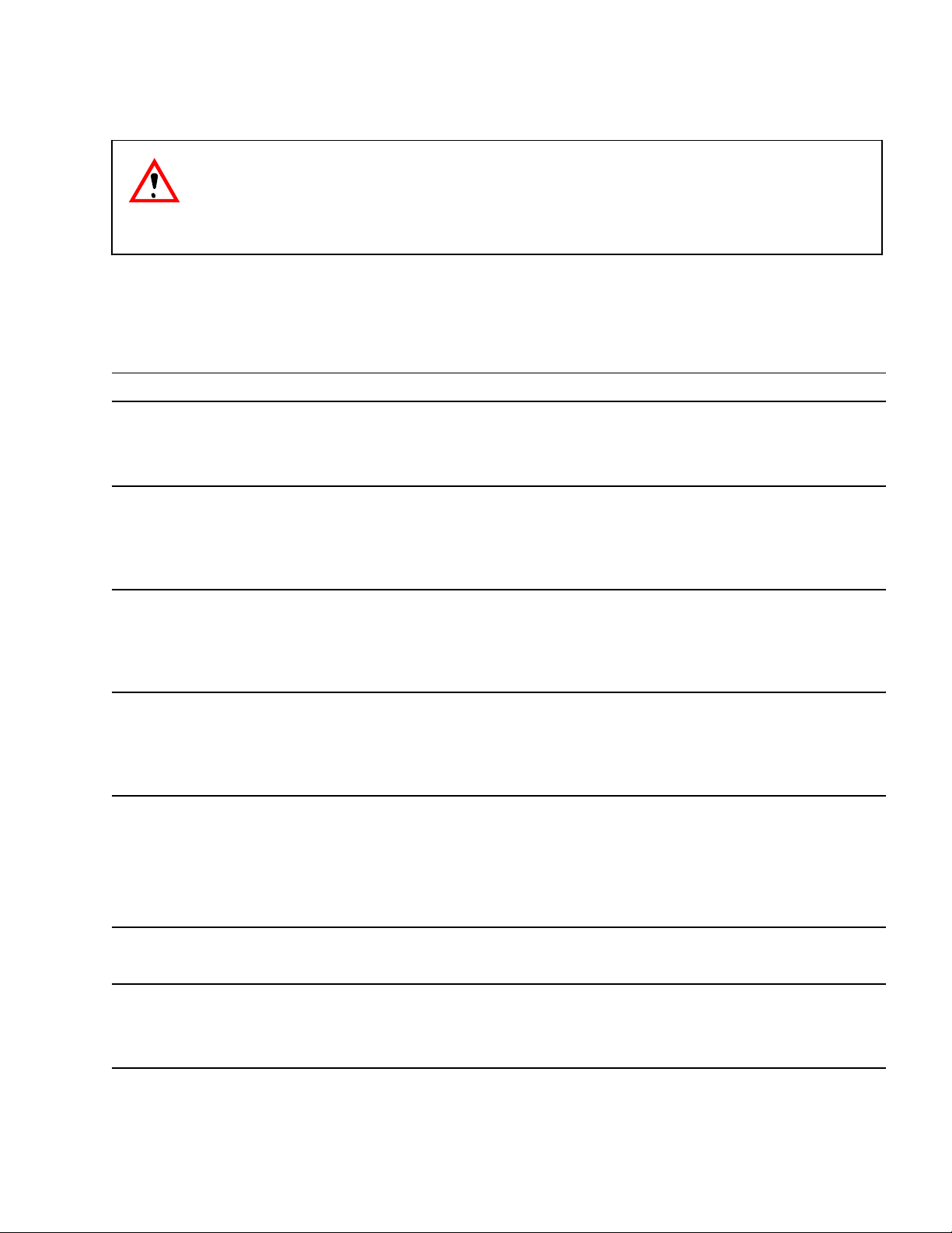
IMPORTANT: Only qualified personnel should service internal components or electrical wiring.
WARNING: If repairs are to be made to a product system, remove quick disconnects from
the applicable product tank, then relieve the system pressure before proceeding. If repairs
aretobemadetotheCO
system pressure before proceeding. If repairs are to be made to the refrigeration system, make sure
electrical power is disconnected from the unit.
Should your unit fail to operate properly, check that there is power to the unit and that the hopper contains ice. If the unit doesnot dispense, checkthefollowingchart under the appropriate symptoms to aid
in locating the defect.
system, stop dispensing, shut off the CO2supply, then relieve the
2
Trouble
BLOWN FUSE OR CIRCUIT BREAKER. A. Short circuit in wiring.
B. Defective gate solenoid.
C. Defective agitator motor.
GATE DOES NOT OPEN. AGITATOR DOES
NOT TURN.
GATE DOES NOT OPEN OR IS SLUGGISH.
AGITATOR TURNS.
ICE DISPENSES CONTINUOUSLY.
SLUSHY ICE. WATER IN HOPPER.
A. No power.
B. Bent depressor plate (does not actuate switch).
C. Defective dispensing switch.
A. Defective gate solenoid.
B. Excessive pressure against gate slide.
C. Defective Rectifier.
A. Stuck or bent depressor plate (does not
release switch).
B. Defective dispensing switch.
C. Improper switch installation.
A. Blocked drain.
B. Unit not level.
Probable Cause
BEVERAGES DO NOT DISPENSE.
BEVERAGES TOO SWEET.
June, 1998
C. Poor ice quality due to water quality or
icemaker problems.
D. Improper use of flaked ice.
A. No 24 volt power to faucets.
B. No CO2pressure.
A. Carbonator not working.
B. No CO2pressure in carbonator.
C. Faucet brix requires adjusting.
7
620911102
Page 10

Trouble Probable Cause
BEVERAGE NOT SWEET ENOUGH.
A. Empty syrup tank.
B. Faucet brix requires adjusting.
BEVERAGES NOT COLD (UNITS WITH BUILT-IN
COLD PLATE).
A. Unit standing with no ice in hopper -- no ice in
cold plate cabinet.
Contact your local syrup or beverage equipment distributor for additional information and troubleshooting of beverage system.
620911102 June, 1998
8
Page 11
CCW
AGITATOR
MOTOR
Q.C.
CONNECTOR
GRN
Y
B
E
B
L
L
L
A
L
U
C
O
E
K
W
W
H
T
N
L
B
W
L
H
A
I
C
T
K
E
TO HINGE
R
GRN
E
D
MOTOR
HEATER
DISPENSE
SWITCH
GATE
SOLENOID
(106VDC)
G
Y
B
G
W
G
E
L
R
H
R
L
A
E
I
E
E
L
C
E
T
N
O
K
E
N
W
B
B
B
B
R
L
E
D
U
E
B
R
B
L
L
A
C
K
R
L
L
E
L
A
N
A
U
U
D
/
C
C
E
E
Y
K
K
E
L
DANGER: ELECTRIC SHOCK HAZARD, DISCONNECT
SERVICE INFORMAT ION
POWER BEFORE SERVICING UNIT.
YELLOW
TRANSFORMER
OPTIONAL
BEVERAGE
YELLOW
TO BEVERAGE FAUCET
OPTIONAL
KEY SWITCH
BLUE
T’STAT LIGHT
2
1
BLUE
ICE LEVEL
SIGNAL OPTION
TO 24V
TRANSFORMER
9 620911102June, 1998
BLACK
BLACK
OPTIONAL
LIGHT
SOCKET
BLACK
MOTOR START
CAPACITOR
OPTIONAL
LIGHT STARTER
WHITE
BLACK
OPTIONAL
LIGHT
BALLAST
BLACK
WHITE
J10
L2
NONC
PINK
RED
BLUE
PINK
COM
NC NO COM
BLACK
AGITATION
TIMER
L1
J9
RED
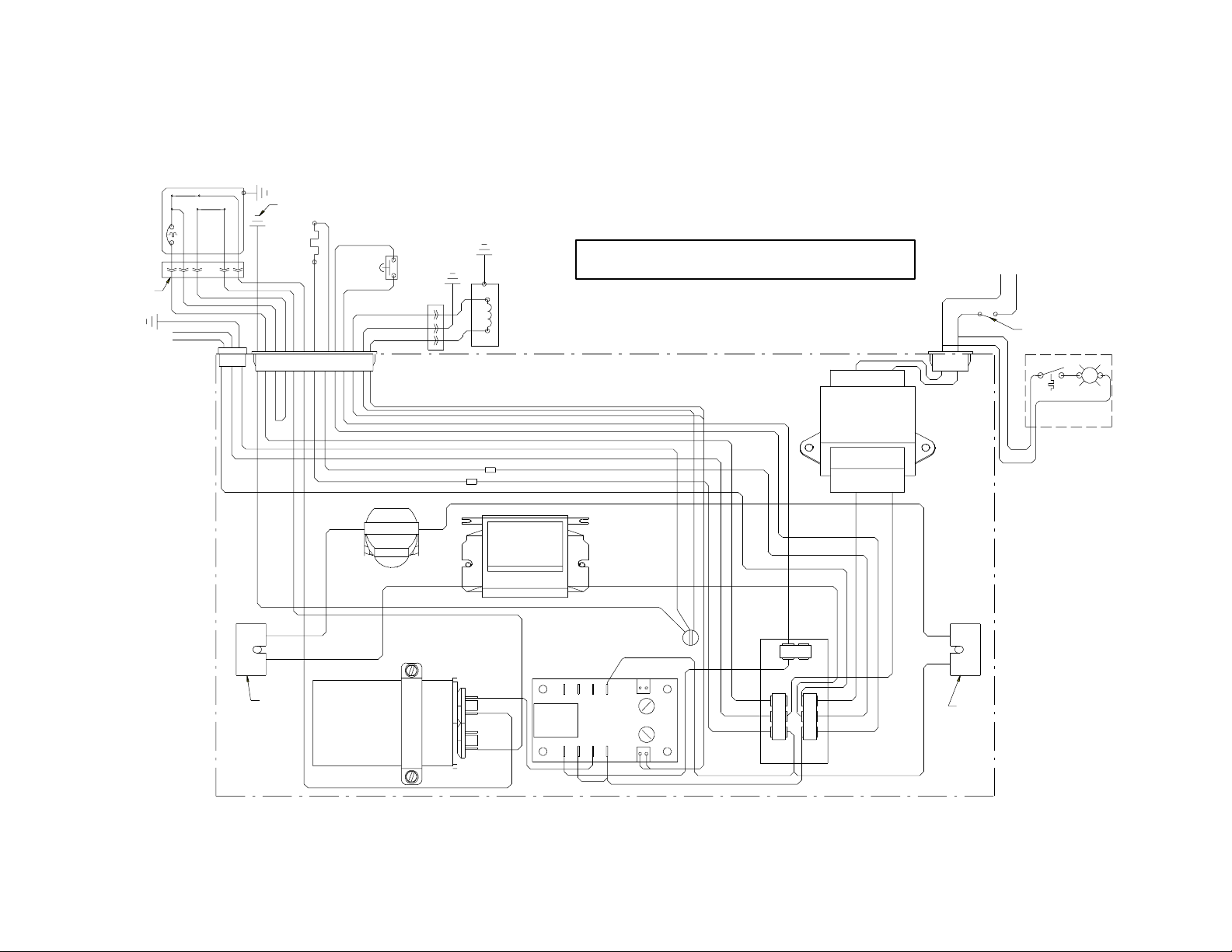
FIGURE 4. WIRING DIAGRAM
W
B
H
L
I
A
T
C
E
B
L
A
C
K
BLACK
BLACK
BLACK
WHITE
K
OPTIONAL
LIGHT
SOCKET
G
R
N
/
Y
E
G
L
R
E
E
N
R
E
D
WHITE
WHITE
WHITE
BLUE
BLACK
Page 12

WARRANTY
IMI Cornelius Inc. warrants that all equipment and parts are free from defects in material and workmanship under normal use and service. F or a copy of the warranty applicable to your Cornelius, Remcor or
Wilshire product, in your country, please write, fax or telephone the IMI Cornelius office nearest you.
Please provide the equipment model number, serial number and the date of purchase.
IMI Cornelius Offices
AUSTRALIA D P.O. 210, D RIVERWOOD, D NSW2210, AUSTRALIA D (61)2 533 3122 DFAX(61) 2 534 2166
AUSTRIA DAM LANGEN FELDE 32 D A-1222 D VIENNA, AUSTRIA D (43)1 233 520 D FAX(43) 1-2335-2930
BELGIUM D BOSKAPELLEI 122 D B-2930 BRAASCHAAT, BELGIUMD (32) 3 664 0552 D FAX (32) 3 665 2307
BRAZIL D RUA ITAOCARA 97 D TOMAS COELHO D RIO DE JANEIRO, BRAZIL D (55) 21 591 7150 D FAX (55) 21 593 1829
ENGLAND D TYTHING ROAD ALCESTER D WARWICKSHIRE, B49 6 EU, ENGLAND D (44) 789 763 101 D FAX (44) 789 763 644
FRANCE D 71 ROUTE DE ST. DENIS DF-95170 DEUIL LA BARRE DPARIS, FRANCE D (33) 1 34 28 6200 D FAX (33) 1 34 28 6201
GERMANY DCARL LEVERKUS STRASSE 15 D D-4018 LANGENFELD, GERMANY D (49) 2173 7930 D FAX (49) 2173 77 438
GREECE D 488 MESSOGION AVENUE D AGIA PARASKEVI D 153 42 D ATHENS, GREECE D (30) 1 600 1073 D FAX (30) 1 601 2491
HONG KONG D 1104 TAIKOTSUI CENTRE D 11-15 KOK CHEUNG ST D TAIKOKTSUE, HONG KONG D (852)789 9882 D FAX (852) 391 6222
ITALY D VIA PELLIZZARI 11 D1-20059 D VIMARCATE, I TALY D (39) 39 608 0817 D FAX (39) 39 608 0814
NEW ZEALANDD 20 LANSFORD CRES. D P.O. BOX 19-044 AVONDALE D AUCKLAND 7, NEW ZEALAND D (64) 9 8200 357 D FAX (64) 9 8200 361
SINGAPORE D16 TUAS STREET D SINGAPORE 2263 D (65) 862 5542 DFAX(65) 862 5604
SPAIN D POLIGONO INDUSTRAIL D RIERA DEL FONOLLAR D E-08830 SANT BOI DE LLOBREGAT D BARCELONA, SPAIN D (34)3 640 2839 D FAX (34) 3 654 3379
USA DONE CORNELIUS PLACE D ANOKA, MINNESOTA D (612) 421-6120 DFAX (612) 422-3255
LD004
4/21/98
June, 1998
10
620911102
Page 13

IMI CORNELIUS INC.
Corporate Headquarters:
Anoka,Minnesota 55303-6234
One Cornelius Place
(612) 421 -6120
(800) 238 -3600
 Loading...