

Remcor LP350A/150S, LP650A/150S, LP650A/150S-B, LP650A/150S-BC, LP350A/150S-B Operator's Manual
...Page 1
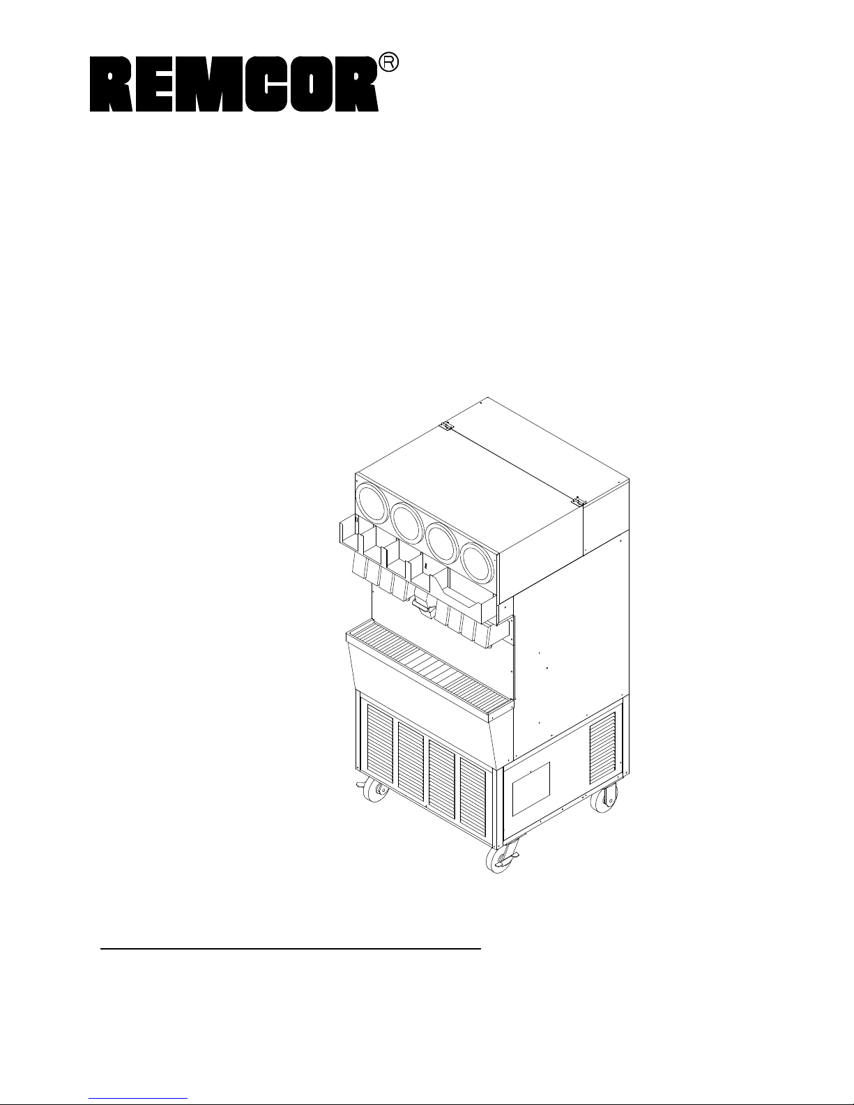
SPIRAL LOW-PROFILE
Operator’s Manual
ICEMAKER-DISPENSER
MODEL:
LP350A/150S, -B, -BC
LP650A/150S, -B, -BC
LP650R/150S, -B, -BC
Part No. 91424
March 1997
Revision D
THIS DOCUMENT CONTAINS IMPORTANT INFORMATION
This Manual must be read and understood before installing or operating this equipment
âREMCOR INC: 1993 - 1995
PRINTED IN U.S.A
Page 2

TABLE OF CONTENTS
SAFETY PRECAUTIONS 1. . . . . . . . . . . . . . . . . . . . . . . . . . . . . . . . . . . . . . . . . . . . . . . . . . .
DESCRIPTION 2. . . . . . . . . . . . . . . . . . . . . . . . . . . . . . . . . . . . . . . . . . . . . . . . . . . . . . . . . . . .
UNPACKING 2. . . . . . . . . . . . . . . . . . . . . . . . . . . . . . . . . . . . . . . . . . . . . . . . . . . . . . . . . .
INSTALLA TION 3. . . . . . . . . . . . . . . . . . . . . . . . . . . . . . . . . . . . . . . . . . . . . . . . . . . . . . . . . . . .
LOCATION 3. . . . . . . . . . . . . . . . . . . . . . . . . . . . . . . . . . . . . . . . . . . . . . . . . . . . . . . . . . . .
PLUMBING 3. . . . . . . . . . . . . . . . . . . . . . . . . . . . . . . . . . . . . . . . . . . . . . . . . . . . . . . . . . .
MODEL LP650R ONLY: REMOTE CONDENSER INSTALLATION 3. . . . . . . . . . . .
ICEMAKER 3. . . . . . . . . . . . . . . . . . . . . . . . . . . . . . . . . . . . . . . . . . . . . . . . . . . . . . . . . .
REMOTE CONDENSER 4. . . . . . . . . . . . . . . . . . . . . . . . . . . . . . . . . . . . . . . . . . . . . . . .
PRE-CHARGED LINE SETS 4. . . . . . . . . . . . . . . . . . . . . . . . . . . . . . . . . . . . . . . . . . . .
ELECTRICAL (SEE FIGURE 4) 5. . . . . . . . . . . . . . . . . . . . . . . . . . . . . . . . . . . . . . . . .
BEVERAGE SYSTEM 8. . . . . . . . . . . . . . . . . . . . . . . . . . . . . . . . . . . . . . . . . . . . . . . . . .
BAG-IN-BOX OPTION 8. . . . . . . . . . . . . . . . . . . . . . . . . . . . . . . . . . . . . . . . . . . . . . . .
INSTALLATION 8. . . . . . . . . . . . . . . . . . . . . . . . . . . . . . . . . . . . . . . . . . . . . . . . . . . . . .
START UP 12. . . . . . . . . . . . . . . . . . . . . . . . . . . . . . . . . . . . . . . . . . . . . . . . . . . . . . . . . . . . . . . .
ICEMAKER 12. . . . . . . . . . . . . . . . . . . . . . . . . . . . . . . . . . . . . . . . . . . . . . . . . . . . . . . . . . .
BEVERAGE SYSTEM 12. . . . . . . . . . . . . . . . . . . . . . . . . . . . . . . . . . . . . . . . . . . . . . . . . .
ADJUSTING WATER FLOW 12. . . . . . . . . . . . . . . . . . . . . . . . . . . . . . . . . . . . . . . . . . . .
BAG-IN-BOX (BIB) GAS OPERATED SYRUP PUMPS 13. . . . . . . . . . . . . . . . . . . . .
OPERA TING INSTRUCTIONS 15. . . . . . . . . . . . . . . . . . . . . . . . . . . . . . . . . . . . . . . . . . . . . . .
Page
ICEMAKER OPERATING INSTRUCTIONS 15. . . . . . . . . . . . . . . . . . . . . . . . . . . . . . .
MAINTENANCE 22. . . . . . . . . . . . . . . . . . . . . . . . . . . . . . . . . . . . . . . . . . . . . . . . . . . . . . . . . . .
CLEANING INSTRUCTIONS 22. . . . . . . . . . . . . . . . . . . . . . . . . . . . . . . . . . . . . . . . . . . .
DISPENSER SECTION 23...........................................
BEVERAGE / BAG-IN-BOX SYRUP SYSTEM 23. . . . . . . . . . . . . . . . . . . . . . . .
MAINTENANCE/ADJUSTMENT PROCEDURE 25. . . . . . . . . . . . . . . . . . . . . . . . . . . . . . . .
CLEARING EVAPORATOR FREEZE-UP 25. . . . . . . . . . . . . . . . . . . . . . . . . . . . . . . . .
CLEANING / REPLACING THE FILTER 25. . . . . . . . . . . . . . . . . . . . . . . . . . . . . . . . . .
CLEANING THE CONDENSER (AIR-COOLED UNIT) 25. . . . . . . . . . . . . . . . . . . . . .
MANUAL FILLING 26. . . . . . . . . . . . . . . . . . . . . . . . . . . . . . . . . . . . . . . . . . . . . . . . . . . . . . . . .
TROUBLESHOOTING GUIDE 27. . . . . . . . . . . . . . . . . . . . . . . . . . . . . . . . . . . . . . . . . . . . . . .
PARTS LIST 38. . . . . . . . . . . . . . . . . . . . . . . . . . . . . . . . . . . . . . . . . . . . . . . . . . . . . . . . . . . . . .
WARRANTY 40..............................................................
i
91424
Page 3

TABLE OF CONTENTS (cont’d)
LIST OF FIGURES
FIGURE 1. PRE-CHARGED LINE SETS 4. . . . . . . . . . . . . . . . . . . . . . . . . . . . . . . . . .
FIGURE 2. PRE-CHARGED LINE SET INSTALLATION 5. . . . . . . . . . . . . . . . . . . . .
FIGURE 3. UNITS WITH BAG-IN-BOX PUMP OPTIONS 6. . . . . . . . . . . . . . . . . . .
FIGURE 4. STANDARD UTILITY LOCATIONS REAR VIEW 7. . . . . . . . . . . . . . . . .
FIGURE 5. MODEL “B” FLOW DIAGRAM 9. . . . . . . . . . . . . . . . . . . . . . . . . . . . . . . .
FIGURE 6. MODEL “BC” FLOW DIAGRAM 10. . . . . . . . . . . . . . . . . . . . . . . . . . . . . . .
FIGURE 7. BEVERAGE SYSTEM SCHEMATIC 11. . . . . . . . . . . . . . . . . . . . . . . . . . .
FIGURE 8. LANCER VALVE 14. . . . . . . . . . . . . . . . . . . . . . . . . . . . . . . . . . . . . . . . . . . . .
FIGURE 9. LP350/150 WIRING SCHEMATIC 16. . . . . . . . . . . . . . . . . . . . . . . . . . . . . .
FIGURE 10. LP 350 / 150 115 / 1 / 60 HZ WIRING DIAGRAM 17. . . . . . . . . . . . . . .
FIGURE 11. LP 650A / 150 WIRING SCHEMATIC 18. . . . . . . . . . . . . . . . . . . . . . . . . .
FIGURE 12. LP 650R / 150 WIRING SCHEMATIC 19. . . . . . . . . . . . . . . . . . . . . . . . .
FIGURE 13. REFRIGERATION SCHEMATIC 20. . . . . . . . . . . . . . . . . . . . . . . . . . . . . .
FIGURE 14. REMOTE CONDENSER SYSTEM DIAGRAM 21. . . . . . . . . . . . . . . . . .
LIST OF TABLES
Page
TABLE 1. SPECIFICATIONS 2............................................
Manufactured Under One or More of the Following Patent Numbers:
3,211,336, 3,274,792, 3,393,839 , 3,517,860, 3,739,842, 4,215,803, 4,227,377, 4,300,3594,346,824
Canadian Patent Numbers912,514 (10/72), 936,855 (11,73), 4,429,543, 4,921,149
Other Patents Pending
91424
Page 4

SAFETY PRECAUTIONS
Always d isconnect power to th e dispenser before servicing or cleaning.
Never place han ds inside of ho pper or gate area without disconnecting power to the dispenser. Agitator rotation
occurs automa tically when the dispenser is energized!
This ice dispenser has been specifically designed to provide protection against personal injury and eliminates
contamination of ice. To insure continued protection and sanit ation, observe the following
ALWAYS be sure the removable lid is properly installed to prevent unauthorized access to the hopper interior and possible contamination of ice.
ALWAYS be sure the upper and lower front panels are securely fastened.
ALWAYS keep area around the dispenser clean of ice cubes.
IMPORTANT INSTALLATION NOTICE
An IMI Cornelius model number 81COR01PS, Filter MUST BE INSTALLED in the water supply line to the icemaker. Failure to do so may result in poor quality ice, low production output and may cause prema ture failure of
icemaker e vaporator and void the extended evaporator warranty.
This icemaker is provided with a stainless steel evaporator, designed to last the life of the product. However,
some of the chemicals in treated and untreated water, specifically chlorine and sulfur (sulfide), ha ve the ability to
attack stainless steel and cause premature failure. An initial investment in proper water treatment will pay for
itself in increased production, quality and long life of the product.
1 91424
Page 5

DESCRIPTION
The REMCOR LOW PROFILE S.I.D. (Spiral Iceâ Icemaker Dispenser) is a unique, self-contained, fre e standing style u nit which automatically makes hard, clear cube-quality ice and stores it in a sealed hopper for sanitary
dispensing. The ice is made by a new, patented process on a spiral shaped stainless steel evaporator and produces tube cube quality ice on the outside of the tubes. There are no augers, no compressing of flaked ice, no
bearings and no high gear motor loads in the icemaking process. The unit has been designed to be simple, yet
effective, to provide many years of trouble free operation.
Table 1. Specifications
Model LP350A LP650A LP650R
Compressor: HP 1/2 HP 3/4 HP 3/4
Refrigerant: R-22 / 1 lb. R502 / 2 lbs. R502 / 8 lbs.
Voltage: 115 / 1 / 60 115 / 1 / 60 115 / 1 / 60
Amps: 16 Amps 16 Amps 16 Amps
Circuit Ampacity:* 20 Amps 20 Amps 20 Amps
Fuse Size: 20 Amps Time Delay 20 Amps Time Delay 20 Amps Time Delay
Ice Storage Capacity: 150 lbs. 150 lbs. 150 lbs.
Ice Making Capacity: Up to 350 lbs./24 hrs. 650 lbs./24 hrs. 650 lbs./24 hrs.
NOTE: *30 amps when unit is supplied with carbonator.
UNPACKING
1. With the unit upright carefully remove the shipping carton. Inspect fo r shipping damage and report any
such dama ge to the shipper immediately.
2. Remove l ower front louvered panel for electrical and start-up process.
3. Remove shipping tape from storage hopper cover and agitator in storage hopper.
291424
Page 6

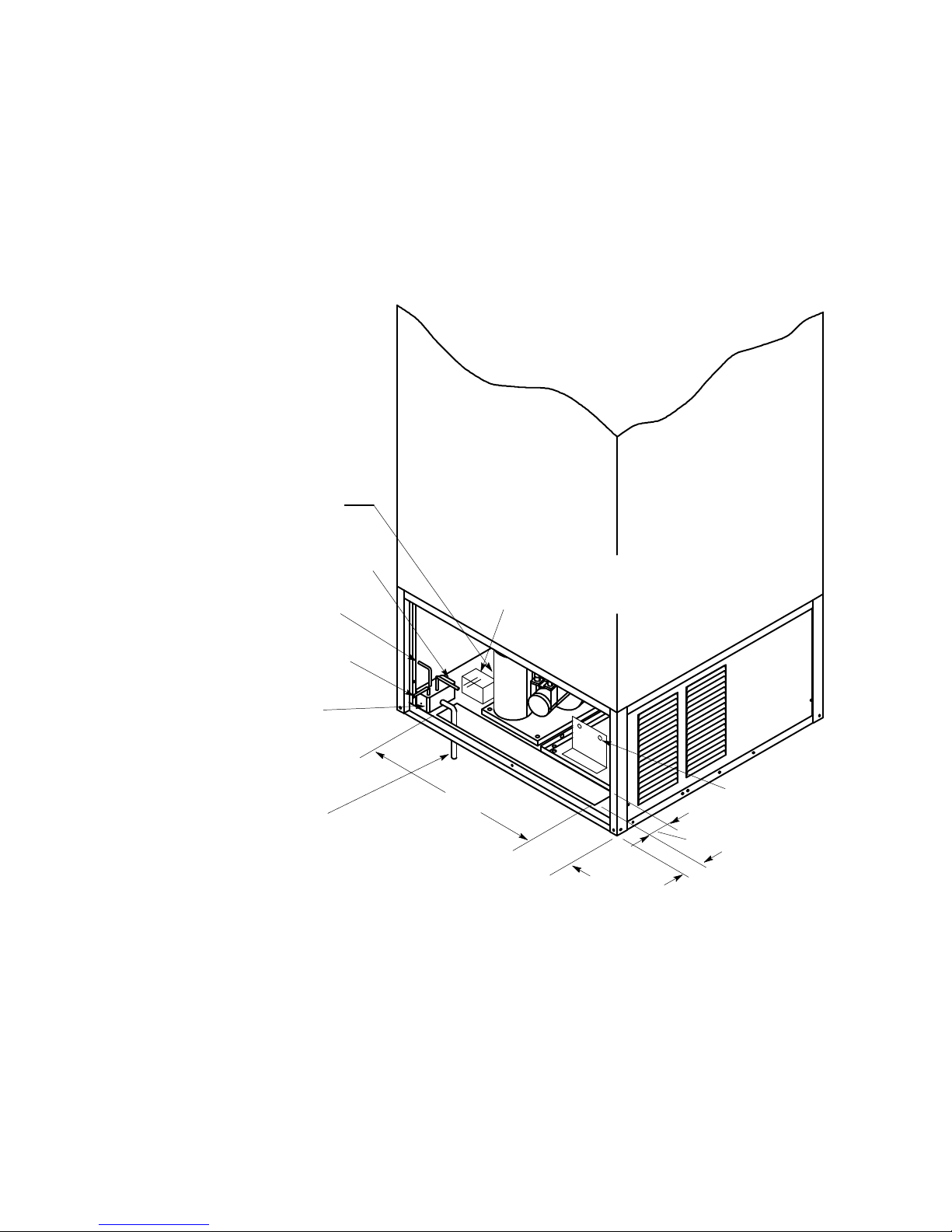
INSTALLATION
WARNING: Only qualified personnel sh ou ld service internal components or electrical
wiring.
LOCATION
Locate the icemaker dispenser indoors i n a well ventilated area. Avoid exposure to direct sunlight and/or heat
caused by radiation. Ambient room temperature must be in the range of 60° to 90° F. Do not install unit in an
enclosed area where heat build-up could be a problem. Note: Air flow direction and spacing required shown in
Figure 1.
Consult Figure 1 for utility connection locations.
PLUMBING
Connect the icemaker to a cold, potable water source, suitable for drinking. This water source must comply wit h
the basic p lumbing code of the Building Officials and Code Administrators International Inc. (BOCA) and the
Food Service Sanitation Manual of the Food and Drug Administration. Do not install unit on a water softener
line. It is recommended that a hand shut-off valve and strainer be used on the incoming supply line. (See Figure
1 for size an d location.) For proper operation of the incoming water supply pressure must be in the range of
30-90 PSIG. Install a pressure regulating valve if above this range!
IMPORTANT: To insure proper icemaker operation and also to reduce the frequ ency o f water-related
service problems, a water filter should be installed. REMCOR recommends the use of IMI Cornelius
filter, model number 81COR01PS.
For specific recom mendations on these filter systems for your local water conditions, consult with a distributor in
your area or contact the filter manufacturer.
Connect separate drain lines to all drain connections. See Figure 2 for size and location. These lines must pitch
downward to and open drain and must contain no traps, or improper drainage will result. All drain connections
must be in accordance with the basic plumbing code of the Building Officials and Code Administrators International (BOCA) and local codes.
NOTE: In areas where con sisten tly warm water temperatures are encountered, the use of a pre-cooler
in the water line is recommended to maximize the ice production of this unit.
MODEL LP650R ONLY: REMOTE CONDENSER INSTALLATION
Remcor Prod ucts remote condenser systems come in three separate packages to complete one remote condenser a pplication. They consist of the icemaker, the remote condenser and the interconnecting pre-charged
line set.
Icemaker
The refrigeration system of a remote condenser systems is similar to a standard air cooled system with the following exceptions described below:
Mixing Valve
This valve is located at the condenser and serves as a head pressure regulating valve. As the temperature at
the condenser drops, the head pressure at the receiver will drop. When this pressure reaches 225 PSIG, the
mixing valve by-passes the condenser and meters hot discharge gas into the receiver, maintaining the 225
PSIG receiver pressure.
3 91424
Page 7
Liquid Receiver
In the icemaker, a 10# liquid receiver is installed to accept the large refrigerant charge that is n ot needed when
the condenser is subjected to higher temperatures.
Pump Down System
To prevent refrigeration migration to the compressor during the off-cycle due to refrigerant to oil attraction or
temperature differential between condenser and compressor, a pump down system has been utilized in this remote condenser system.
A solenoid valve has been installed in the liquid line to the TXV and is open during normal icemaking operation.
When the bin stat opens, the solenoid valve closes and stops the flow of refrigerant to the low side of the system. The compressor is kept running by the pump down low pressure control, thereby pumping any remaining
refrigerant out of the low side into the high side liquid receiver. When the low die pressures reaches 5# the compressor is turned off. The low side control is a recycling control and if refrigerant leaks into the low side and the
pressures reaches 55# the compressor is restarted, removing the unwanted refrigerant.
REMOTE CONDENSER
The remote condenser is an air-cooled fin-pack that can be mounted in the horizontal or vertical position. Care
should be taken in the installation site to reduce prevailing wind restraints and to keep the air entrance away
from other systems air discharge. This will keep the remote system operating at its’ designed efficiencies.
This remote condenser system is designed to operate in temperatures of --20 degrees F through 120 degrees F.
These limits should be considered when installing equipment.
The remote condenser is supplied with a low ambient mixing valve that assures that the receiver will under all
temperatures have a liquid pressure of 225 PSIG. This is required for proper txv operation and to assure sufficient pressure when hot gas by-pass is required. This valve eliminates the requirement of any fan cycling controls.
The remote condenser is not required to cycle with the hot gas portion of the ice making cycle. The wiring of the
condenser can either be wired to a separate power source or, to allow the condenser to shut down with the icemaker, it may be wired per the electrical diagram enclosed.
NOTE: When servicing remote condenser make sure the power is disconnected.
Electrical volt age requirements are rated on the condenser f or separate power sourcing.
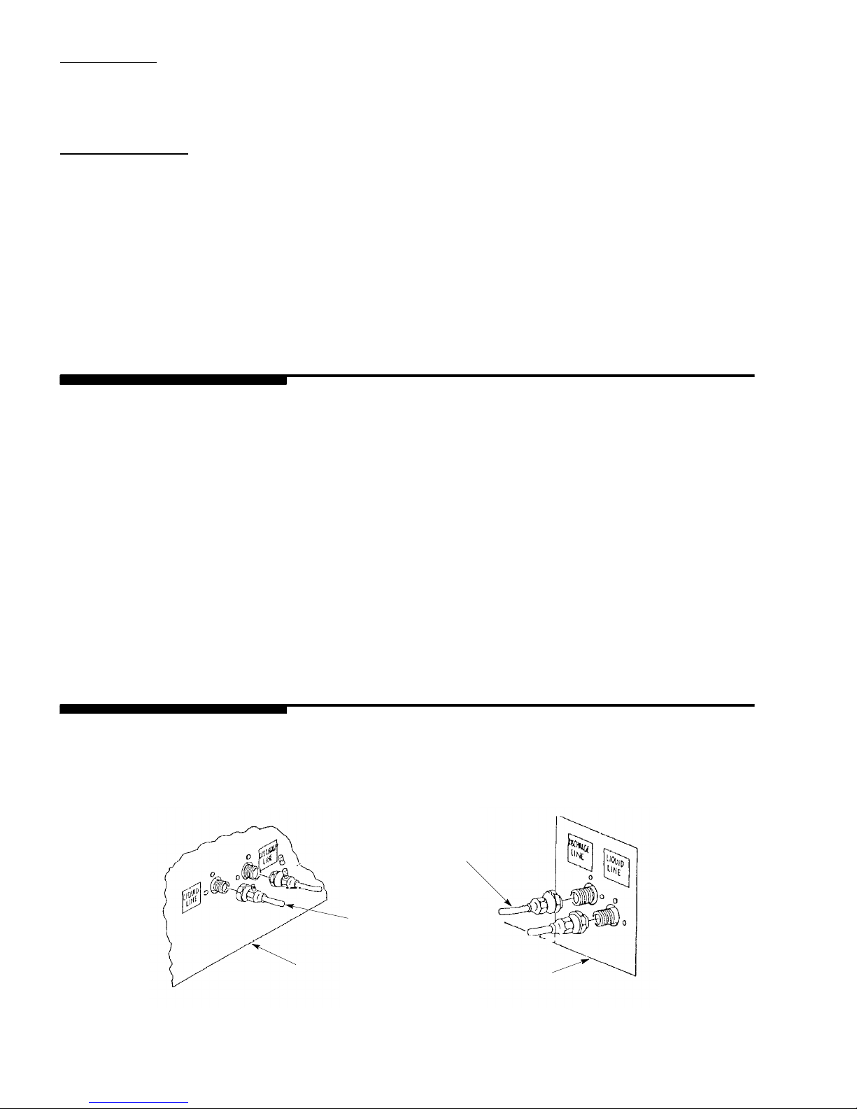
PRE-CHARGED LINE SETS
The pre-charged line sets (25 ft. long or 40 ft. long) join tog ether a totally sealed pre-charged system ready for
operation after installation. The line set is supplied with 3/8” quick couplings for the liquid line and 1/2” quick
couplings for the discharge line. As these couplings are “one time” couplings, if they are ever removed and reinstalled, the system refrigerant charge will be lost and an evacuation and recharge of the system will be necessary.
DISCHARGE LINE
1/2-IN. DIA.
FIGURE 1. PRE-CHARGED LINE SETS
REMOTE
CONDENSER
LIQUID LINE
3/8-IN. DIA.
ICEMAKER
491424
Page 8
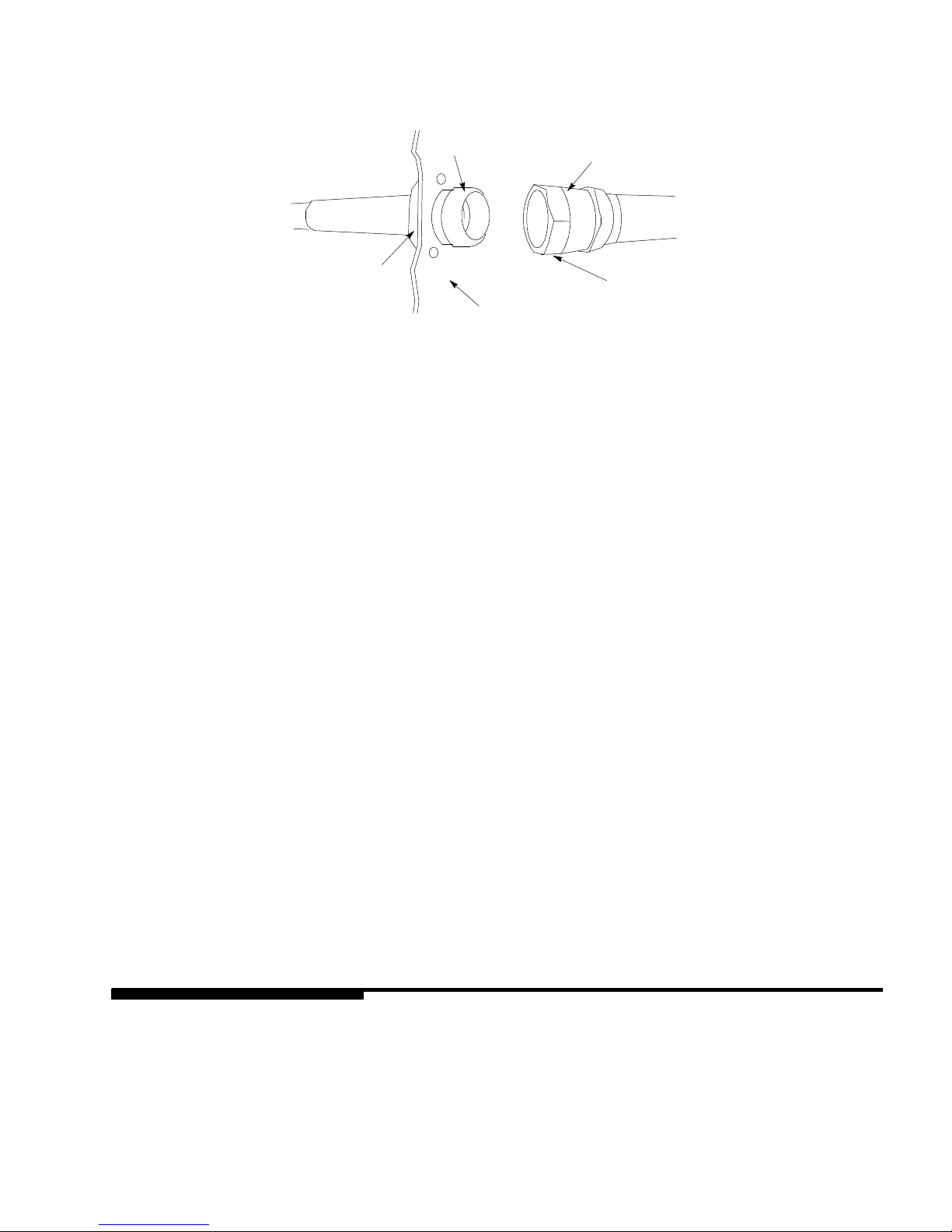
When routing pre-charged line set, make sure that couplings are lubricated with refrigerant oil to assure proper
trouble free assemble.
5502 COUPLING
HALF TALL FLANGE
5505 COUPLING HALF
6-HOLE FLANGE
PART NO. 150-22
PANEL OR BULKHEAD
UNION NUT
FIGURE 2. PRE-CHARGED LINE SET INSTALLATION
1. Remove d ust cap and plugs if used, making sure that component synthetic seals are intact.
2. Wipe off coupling seals and threaded surfaces with a clean cloth to prevent the inclusion of dirt or any foreign material in the system.
3. LUBRICATE rub ber seal in male half with refrigeration oil. Thread coupling halves together by hand to insure prop er mating of threa ds, Use proper size wrenches (on coupling body hex and on union nut) and
tighten until coupling bodies “bottom” or a definite resistance is felt. Using a marker or ink pen, mark a line
lengthwise from the coupling hex to the bulkhead. then tighten an additional 1/6 to 1/4 turn. The misalignment of the line will show the degree of tightening. This final turn is necessary to insure tha t the knife edge
metal seal bites into the brass seat of the coupling halves, forming the leakproof joint. If torque wrench is
used, the following torque values are recommended:
Coupling Size Ft. Lbs.
--8 35
--12 50
--16 65
Routing of line sets are a very important factor in trouble free installation.
1. Make sure condenser will be located above the icemaker.
2. Route line sets to keep excess tubing inside of building.
3. When coiling excess tubing make sure coils runs vertically with the flow of refrigerant.
ELECTRICAL (see figure 4 )
A 4 X 2 junction box is located at the rear of the unit for the supply hook-up. Connect the icemaker to its’ own
individual circuit per the National Electric Code and Local Code (see SPECIFICATIONS for ampacity and fuse
size).
IMPORTANT: The wire size must be adequate for the ampacity rating and the supply voltage must be
within a range of ± 10% for proper icemaker operation.
NOTE: That the unit requires a 2-wire systems plus earth ground for proper operation.
5 91424
Page 9
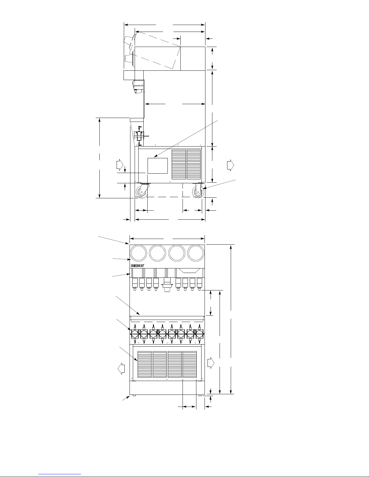
34 3/4
30
10 1/2
10
34
AIR FLOW
TOP ACCESS FOR MANUAL
FILL OF HOPPER
OPTIONAL
OPTIONAL
4 1/8
5 1/2
2
CUPS CUPS CUPS CUPS
26 1/4
30
32
STRAWS
32 3/8
OPENING FOR BEV
LINES 6 1/2 X 8 1/2
15 5/8
AIR FLOW
KICK PLATE
REMOVABLE
6 3/8
(OPTIONAL)
1 1/28
SINK
BAG IN BOX SYRUP
PUMPS (8) (OPTIONAL)
ALL PANELS
REMOVABLE
AIR FLOW
AIR EXHAUST
(LEFT OR RIGHT SIDE)
FRONT AND SIDE KICK
PLATE (OPTIONAL)
FIGURE 3. UNIT S WITH BAG-IN-BOX PUMP OPTIONS
PUSH FOR ICE
11
64 3/8
45
AIR FLOW
1/2
3 19/325 3/4
691424
Page 10
*115V, 1/4HP, 4 AMP REMOTE
FAN MOTOR FOR REMCOR-SUPPLIED
REMOTE CONDENSER
OPTIONAL CARBONATOR
(LOWER REAR LOUVERED PANEL REMOVED)
WHITE (NEUTRAL)
GREEN (GROUND)
BLACK (HOT)
4? X 2? HANDY BOX FOR
SUPPLY HOOKUP
SUPPLY CONDUIT (ROUTE
THROUGH BOTTOM OPENING)
ROUTE ALL UTILITIES THROUGH BOTTOM OPENING:
4? X 2? HANDY BOX FOR REMOTE
*LP 650R ONLY:
CONDENSER FANHOOKUP
22 7/8
4 1/2
1. ICEMAKER W ATER IN 3/8-IN. I.D. TUBING
2. CARBONATED WATER IN 3/8-IN. I.D.
3. TUBING (COLD PLATE UNITS)
4. DRAIN 1-IN. I.D. BY 1 1/4-IN O.D. TUBING
LP 650R ONLY: REMOTE
CONDENSER LINE
CONNECTIONS
2 7/8
1 1/4
FIGURE 4. STANDARD UTIL ITY LOCATIONS REAR VIEW
7 91424
Page 11

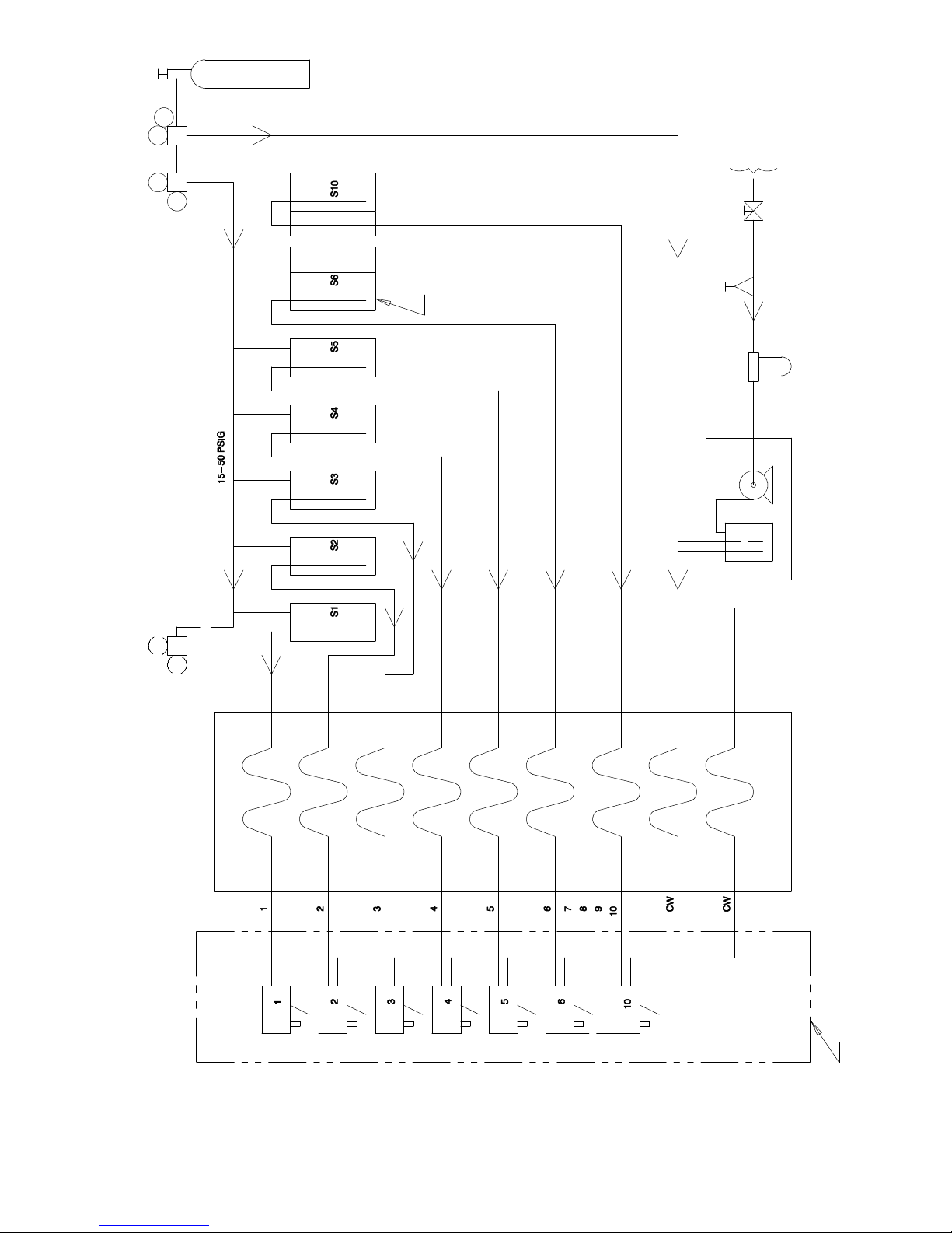
BEVERAGE SYSTEM
“B”, “-BC” Models: connect the beverage system product lines as indicated in “B” and “BC” units, Figures 5 and
6 respectively. This work should be down by a qualified service person. Note that the hoses are marked with
number S1, etc. for syrup connection and “CW” for carbonated water connections.
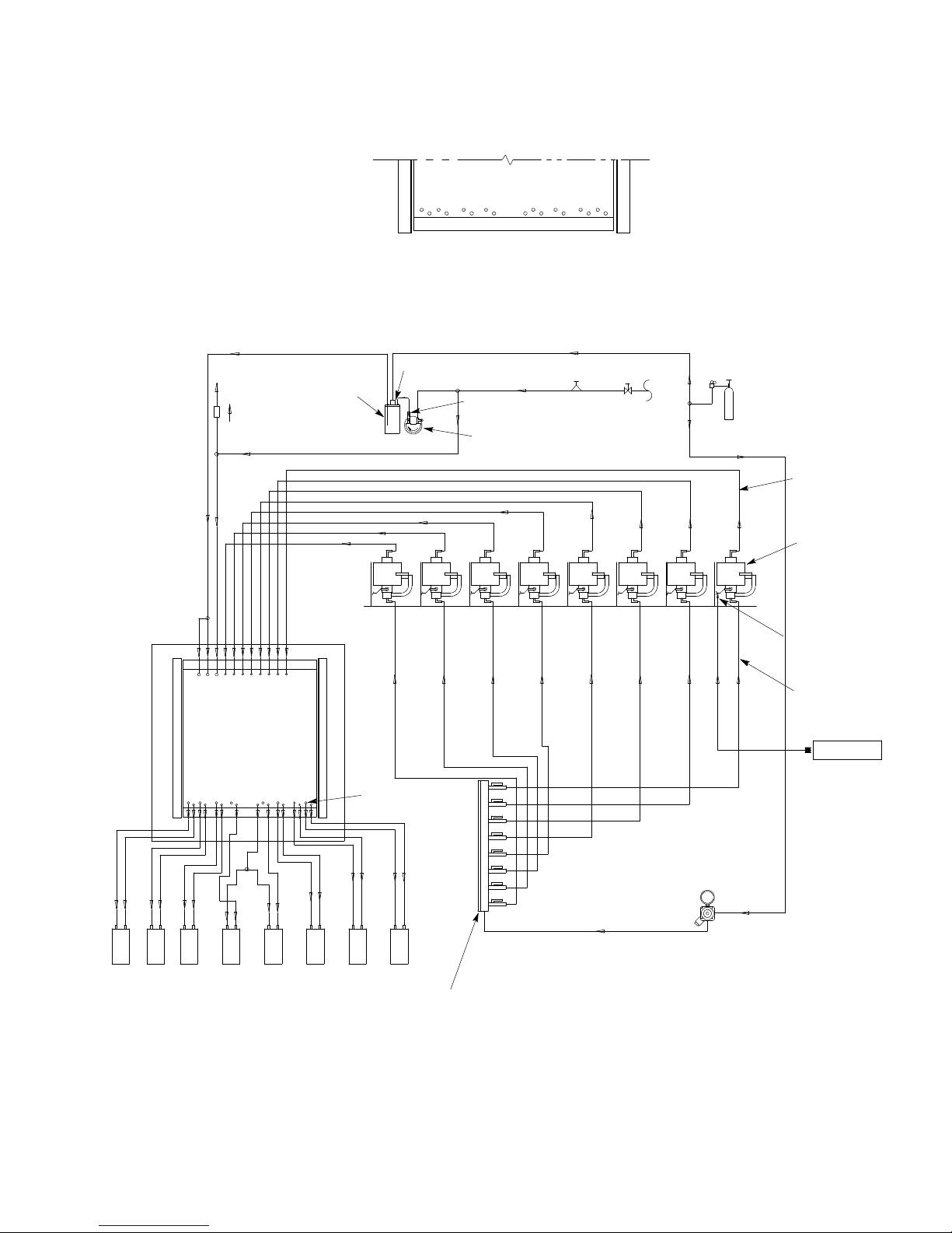
Bag-In-Box Optio n
The unit has a built-in cold plate, carbonator, beverage fau cets and syrup pumps. It is de signed to be supplied
directly from the Bag-in-Box syrup containers with no additional cooling required. (see Figure 7)
Installation
1. Connect the beverage system syrup lines (tubing marked S1 through S10) to the Bag-in-Box containers.
2. Hook up th e carbonator water line (marked “CW”) to a potable water supply.
3. Hoot up the carbonator and syrup pump CO2line (marked “CO2”) to the CO2supply tan k.
NOTE: This work should be done by a qualified service person.
891424
Page 12
TANK
2
CO
WATER
SUPPLY
REGULATORS
TANKS
SYRUP
REGULATOR
60 -- 100 PSIG
OPTIONAL PRESSURE
(7 THRU 10) ARE PERMITTED
4 ADDITIONAL FAUCETS AND TANKS
BEER
DIET OR ROOT
OPTIONAL FOR
5 -- 15
PSIG
FILTER
FOR REFERENCE ONLY
NOT FOR CONSTRUCTION
CARBONATOR
FAUCETS
FIGURE 5. MODEL “B” FLOW DIAGRAM
9 91424
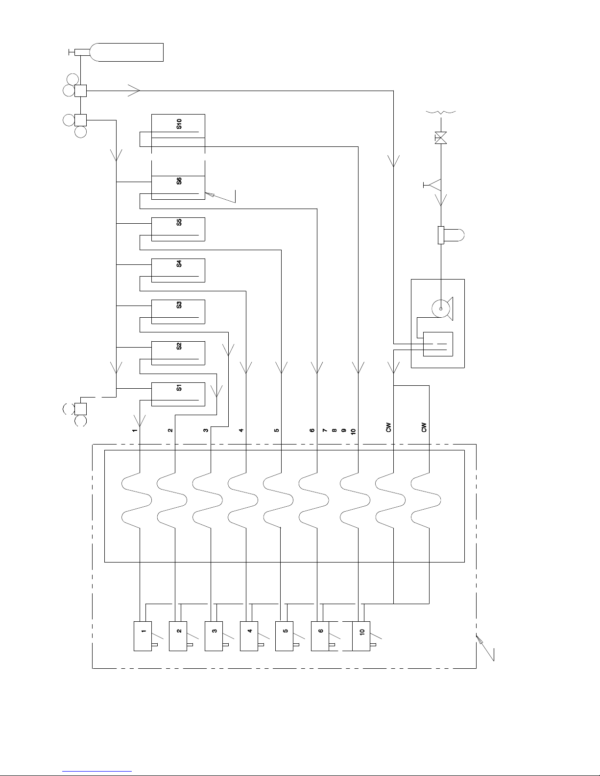
COLD PLATE
ITEMS OUTSIDE BROKEN LINES
ARE NOT INCLUDED. (2) CENTER
FAUCETS CAN BE CONVERTED
TO NON--CARBONATED WATER.
Page 13
TANK
2
CO
WATER
SUPPLY
REGULATORS
FOR REFERENCE ONLY
NOT FOR CONTRUCTION
SYRUP
TANKS
OPTIONAL
PRESSURE
REGULATOR
60--100 PSIG
15-50 PSIG
OPTIONAL
ROOT BEER
FOR DIET OR
5--15
PSIG
4 ADDITIONAL FAUCETS AND
TANKS (7THRU 10) ARE PERMITTED
FILTER
CARBONATOR
FAUCETS
FIGURE 6. MODEL “BC” F LOW DIAGRAM
COLD PLATE
TO NON-CARBONATED WATER
FAUCETS CAN BE CONVERTED
ITEMS OUTSIDE BROKEN LINES
ARE NOT INCLUDED (2) CENTER
1091424
Page 14
CARBONATED
WATER
TO
ICE
MAKER
CHECK VALVE
PLAIN WATER
WATER
TANK
1 2 3 4 5 6 7 8
CO2CHECK
VALVE
CARBONATOR
1
2 3 4 5
DETAIL A
OPTIONAL
PRESSURE REGULATOR
DUAL CHECK
VALVE
WATER
PUMP
90-100 PSIG
REGULATOR
WATER
SUPPLY
6 7 8
CO2TANK
SYRUP OUT
(TYP)
BAG-N-BOX
PUMPS (8)
TO BAG-N-BOX
SYRUP (8)
2
1 876543CW
ICE COOLED
COLD PLATE
21 3 4 5
FAUCETS
(FRONT OF UNIT)
SEE DETAIL A
6 7 8
SYRUP PUMP
DISTRIBUTOR (CO2)
SYRUP PUMP CO
REGULATOR (50PSIG)
2
CO2(50PSI)
TYP
BAG-N-BOX
SYRUP (TYP)
FIGURE 7. BEVERAGE SYSTEM SCHEMATIC
11 91424
Page 15

START UP
ICEMAKER
1. Open the hinged top cabinet. Remove ice drop cover and storage hopper cover. Remove the lower front
panel directly above the sink.
2. Turn on water to icemaker.
3. Depress the switch to verify that water inlet valve opera tes and that the water drain line is open an d not
plugged. Continue to depress switch until water is observed flowing in “ diameter clear icemaker drain line.
4. Put the “stop/run” switch in the “run” positio n. Observe that the icemaker goes through proper icemaking
and harvest cycles. If unit malfunctions, consult the TROUBLESHOOTING GUIDE.
NOTE: Do to meltage loss because of warm storage hopper, it will take lon ger to fill the hopper the
first time than when the icemaker has been operating continuously.
5. Depress the vend switch lever. Check that both the gate solenoid and agitator motor are energized simultaneously to lift the gate slid and rotate the agitator in the storage hopper, respectively. I f either component
malfunctions, consult the troubleshooting guide with water before starting unit. Put the stop/rum switch in
the “run” position. Observe that the icemaker goes through proper icemaking and harvest cycle. If unit malfunctions, consult TROUBLESHOOTING GUIDE. Replace the ice drop and hop per covers.
BEVERAGE SYSTEM
6. Start up the beverage system and adjust the faucets to the proper brix, according to t he following steps. It
will take approximately one (1) hour from the initial machine start-up for the cold plate to be at full capacity.
7. turn on and set CO2pressure on CO2tank regulator to 100 PSIG.
8. Purge all carbonated plain water lines until a steady stream of water flows out of each faucet.
ADJUSTING WATER FLOW
9. Allow u nit to make enough ice to cover the cold plate (approximately one hour from initial start-up).
A. The water flow may be adjusted to 2.50 oz/sec (74 ml. sec). This will produce a finished drink flow of
3.0 oz/sec (88.8 ml/sec).
B. Slide up I .D. panel until flow control adjustments are exposed (see Figure 8).
C. Remove nozzle by twisting counter clockwise and pulling down.
D. Remove diffuser by pulling down.
E. Install Lancer (yellow) Syrup Separator in place of nozzle.
F. Activate valve to fill separator syrup tube.
G. Hold a brix cup under the syrup separator and dispense water into cup for 3 seconds. The water
should be even with the top line (FFV).
H. To obtain desired water flow rate, use a screwdriver to adjust water flow control (See Figure 3).
1291424
Page 16

BAG-IN-BOX (BIB) GAS OPERATED SYRUP PUMPS
10. Connect all BIB connectors to appropriate flavor syrup, matching the faucet flavor (S1 to Faucet #1, etc.).
11. Remove top lower panel on the unit (just below) the beverage faucets) to access the CO2distributor manifold. Turn on CO2supply (50 PSI G) to each pump at manifold. Pumps will run until the syrup lines are
pressurized and will automatically shut off. Operate each faucet until a steady stream of syrup is dispensed
free of air bubbles.
12. Adjusting water to syrup ratio (BRIX).
A. Hold the BRIX cup under the syrup separator and activate. Check ratio (BRIX).
B. To obtain desired ration, use screw driver to adjust syrup flow control, (see Figure 8), until the syrup
and water levels are even.
Use the 5:1 ratio for all flavors except diet Coke. Use the 5.5:1 ratio for diet Coke.
C. Remove syrup separator.
D. Install diffuser and nozzle.
E. slide down I.D. panel.
NOTE: There are syrup and water shut-off valves located at the back of each faucet. These sh ou ld b e
fully open at all times and only be closed for service of if a leak occurs.
13. After completion of the start-up procedures, clean the unit. (See CLEANING INSTRUCTIONS).
13 91424
Page 17

COVER MOUNTING
SCREW
FLOW CONTROL
WATER
I.D. PANEL
(SHOWN IN OPEN
POSITION)
FLOW CONTROL
SYRUP
INCREASE DECREASE
SODA LEVER
(OPTIONAL)
CUP LEVER
INCREASE DECREASE
COVER
DATE OF MANUFACTURE
SERIES NO.
NOZZLE
WATER SYRUPSYRUPWATER
SHUTOFF CLOSEDSHUTOFF OPEN
FIGURE 8. L ANCER VALVE
1491424
Page 18

OPERATING INSTRUCTIONS
ICEMAKER OPERATING INSTRUCTIONS
A temperature sensing bulb located in the storage hopper starts and stops the icemaking process (compressor)
in response to the ice level in the hopper. With this ice level control “calling” fo r ice (hopper ice level is low), the
total cycle timer energized. This timer , in turn energizes the harvest and agitation timers for their respective
“on” times. The chart below details this sequence of events:
CONTROLLER
Total Cycle
Time
Start - 34 seconds X 1. Hot gas solenoid valve open.
34 - 37 Seconds X 1. Agitator motor on.
34 - X
55 - ** X X
34 - * X 1. Hot gas solenoid valve closed.
* LP350 - 510 seconds ** LP350 - 55 seconds (21 sec. harvest)
LP650 - 570 seconds LP650 - 75 seconds (41 sec. harvest)
At the 34 second point in the cycle, the hot gas solenoid valve closes and ice begins to form on the stainless
steel tubing coils of the evaporator. Ice will continue to form on these coils for the remainder of the cycle time
(*seconds). At the e nd of the ice making cycle, the total cycle timer (repeat) starts the harvest portion of the
cycle again.
When ice contacts the control bulb in the storage hopper, the control switches the compressor off. This control
(thermostat) also switches off power to the total cycle timer. With power de-energized, the timer resets itself to
the “start” portion of the cycle. Therefore, the unit will always start with the hot gas/harvest portion of the ice
making cycle to ensure that the evaporator is cleared of any remaining ice.
Timer
Harvest
Timer
Agitation
Timer Action
1. Harvest motor on.
2. Water fill valve on.
1. Harvest and agitator motors off.
2. Water fill valve off.
15
91424
Page 19

CARBONATOR
L
STOP/
RUN
RED
BLK
TOTAL CYCLE
RED
COM
NO
NC
RED
HARVEST TIMER
C
NO
NC
HPS
TIMER
R
E
D
L1L2
COM
NO
NC
C
NO
NC
115/1/60 Hz
DUPLEX
LPS
BLUBLUORGBLK
RED
BLK
SUMP PUMP
WHTBLK
BIN T’STAT
2
1
3
RED
R
E
D
B
L
U
E
BRN
START
RELAY
RUN
CLEAN
NC
NO
COMPRESSOR
TP
C
CONDENSER FAN
BLK
AIR PUMP
YEL
HG SOL VAL VE
WHT
RED WHT
FILL
SWITCH
HARVEST MOTOR
CAP
WATER FILL VALVE
C
BRN
RED
BLUE
R
START CAP
S
WHT
N
WHT
BLK
WHT
WHT
WHT
R
E
D
WHT
AGITA-
TION
L2
COM
NO
NC
VEND SWITCH
BLK RED WHT
F
BLK WHT
BLK WHT
L1
TIMER
BLK WHT
BEVERAGE TRANSFORMER
24 VTO BEVERAGE FAUCETS
RED
COM
NC
RED WHT
NO
CAP
R
E
D
MOTOR HEATER
LIGHTED DISPLAY
BLKBLK
F
AGITATOR MOTOR
CW ROTATION
MAIN
AUX
GATESOLENOID
BLUE
TP
YEL
FIGURE 9. L P350/150 WIRING SCHEMATIC
91424
16
Page 20

WHT
WHT
RED
WHT
RED
2
C
YEL
3
S
RED
HARVEST TIMER
C
NO
NC
HIGH PRESSURE
START
RELAY
RED
BLUE
COMPRESSOR
STARTCAP.
BLUE
BIN
T”STAT
HG SOL VALVE
BLUE
RED
1
BLUE
2
3
WHT
BLUE
LPS
BLUE
BLUE
WHT
RED
BLUE
HARVEST MOTOR
RED
YEL
S
C
BLK
1
RED
BLUE
R
COMPRESSOR
MOTOR
RED
SAFETY CONTROL
BRN
WHT
ORN
WATER FILL
VALVE
L2 L1
RED
RED
BRN
TIMER
L2
C
NO
NC
RED
WHT
L1
C
NO
NC
BLUE
RED
RED
RED
C
NO
NC
TOTALCYCLE
WHT
C
FILL
SWITCH
NCNO
BLK
BLUE
BLK
RED
YEL
AGITATION
TIMER
C
NO
RED
NC
RED
RED
R
E
D
WHT
RECEPTACLE
WHT
BLK
DUPLEX
GRN
WHT
BLK
BLK
RED
RED
BLK
YEL
L1L2
C
NO
NC
BLK
BLK
RED
BLK
GRN
WHT
WHT.
WHT
BLK.
WHT
RED
WHT
BLK
WHT
BRN
RUN
STOP
RUN
WHT BLK
CLEAN
FUSE 1- -1/4 AMP
TIME DELAY
RED
RED
WHT
115V,60HZ,1Ph,30AMP.
FIELD SUPPLIED
WHT
BLK
GRN
JUNCTION BOX
BLK
YEL
WHT
CARBONATOR
RED
BLUE
AGITATOR
MOTOR
VEND
SWITCH
NC
NO
RED
SUMP PUMP
WHT
F
BLK
WHT
BLUE
BALLAST
PLUGGED INTO
DUPLEX
LIGHT
YEL
STARTER
LIGHTED
DISPLAY
WHT
MOTOR HEATER
C
BLK
BEVERAGE SYSTEM
BLUE
24 VOLTS TO
BLUE
WHT
BLK
BEVERAGE
SYSTEM
TRANSFORMER
NOTES:
1. BLACK PRINTING ON WHITE BACKGROUND.
2. ADHESIVE PROTECTIVE BACKINT TO BE SUPPLIED WITH A TAB OR SLIT FOR EASY REMOVAL FROM LABEL,
3. ARTWORK TO BE SUPPLIED BY REMCO.
4. MATERIAL SPECIFICATIONS:
GLOSS 60 LB. LITHOPAPER WITH PERMANANT S246 ACRYLIC ADHESIVE.
ACCEPTED VENDOR
GRAPHIC SOLUTION
ORG
BLKYEL
AIR PUMP
GATE
SOLENOID
POWER IN
FIGURE 10. L P 350 / 150 115 / 1 / 60 HZ W IRING DIAGRAM
17
91424
Page 21

CARBONATOR
L
STOP/
RUN
BLK BLU
RED
RED
RED
BLK
BLK
TOTAL CYCLE TIM-
COM
NO
NC
RED
HARVEST TIMER
C
NO
NC
115/1/60 Hz
DUPLEX
HPS
ER
R
E
D
LPS
BLUORG
L1L2
COM
NO
RED
NC
C
NO
NC
BLK
R
E
D
BRN
B
L
U
E
CLEAN
BIN T’STAT
2
RED
START
RELAY
RUN
RED
FILL
SWITCH
NC
NO
1
3
COMPRESSOR
TP
C
CONDENSER FAN
BLK
YEL
WHT
CAP
BRN
C
SUMP PUMP
WHT
R
S
WHT
AIR PUMP
HG SOL VAL VE
HARVEST MOTOR
RED
BLUE
WATER FILL VALVE
WHT
RUN CAP
START
CAP
BLK
WHT
WHT
N
WHT
WHT
R
E
D
BLK
BLK
F
AGITATION
TIMER
COM
NO
NC
VEND SWITCH
BLK
BLK
WHT
L1L2
RED
COM
NO
NC
LIGHTED DISPLAY
BLK
BEVERAGE TRANSFORMER
24 V TO BEVERAGE FAUCETS
R
E
D
RED
RED
CAP
BLK
GATESOLENOID
F
AUX
MOTOR HEATER
AGITATOR MOTOR
CW ROTATION
MAIN
BLUE
YEL
WHT
TP
WHT
WHT
WHT
WHT
FIGURE 11. LP 650A / 150 WIRING SCHEMA TIC
91424
18
Page 22

L
BLK
BLK
CARBONATOR
STOP/
RUN
ORG
RED
RED
RED
TOTAL CYCLE
COM
NO
NC
RED
C
NO
NC
BLK
HPS
TIMER
L1L2
COM
NO
NC
HARVEST TIMER
R
E
D
BLK
115/1/60 Hz
DUPLEX
RED
C
NO
NC
BIN T’STAT
R
E
D
B
L
U
E
BRN
LPS
2
RED
CC
START
RELAY
RUN
CLEAN
NC
NO
1
3
TP
RED
CAP
FILL
SWITCH
C
WHT
COMPRESSOR CONTACTOR
CC
COMPRESSOR
C
YEL
HG SOL VAL VE
BRN
WATER FILL VALVE
LIQUID LINE
SOLENOID VALVE
REMOTE CONDENSER
FAN MOTOR
R
S
AIR PUMP
WHT
HARVEST MOTOR
RED
BLUE
SUMP PUMP
RUN CAP
WHT
WHT
WHT
WHT
N
WHT
START
CAP
WHT
YEL
BLK
BLK
R
E
D
F
AGITATION
TIMER
COM
NO
NC
VEND SWITCH
BLK
BLK
L1L2
RED
COM
NO
NC
BEVERAGE TRANSFORMER
24 V TO BEVERAGE FAUCETS
RED
CAP
BLK
R
E
D
F
RED
MOTOR HEATER
LIGHTED DISPLAY
BLK
AUX
GATESOLENOID
WHT
AGITATOR MOTOR
CW ROTATION
MAIN
BLUE
YEL
WHT
TP
WHT
WHT
WHT
WHT
FIGURE 12. L P 650R / 150 WIRING SCHEMATIC
19
91424
Page 23

TXV
BULB
COMPRESSOR
HIGH SIDE
SERVICE
PORT
LOW PRESSURE
CONTROL
LOW SIDE
SERVICE
PORT
HIGH
PRESSURE
CONTROL
HOT GAS
SOLENOID
VALVE
AIR- -COOLED MODELS
A
CONDENSER
CONDENSER
FAN
B
EVAPORATOR
FILTER/
DRIER
TXV
PRESSURE
TAP
SUCTION
ACCUMULATOR
EXPANSION
VALVE(TXV)
FIGURE 13. REFRIGERATION SCHEMATIC
91424
20
Page 24

FIGURE 14. REMOTE CONDENSER SYSTEM DIAGRAM
21
91424
Page 25

MAINTENANCE
It is recommended that the air-cooled condenser be cleaned ever 3 months or sooner, depending on the operating environment for proper refrigeration system performance. Check that this is free of dirt/foreign material that
could cause air flow blockage.
Cleaning of the icemaker is recommended on a regular basis not only for sanitary reasons but also to maintain
the performance of the unit. Build-up of lime and scale can hinder icemaking prod uction rates and interfere with
proper dispensing of the ice. See the CLEANING SECTION for the recommended procedure.
periodically, check the vending area sink for proper water drainage. Remove any foreign material from the sink
to prevent drain blockage.
CLEANING INSTRUCTIONS
IMPORTANT:
The icemaker should be cleaned at a minimum of 3 month in tervals or more frequ ently ,depending on
local water conditions. The storage hopper interior should be cleaned at least once a month.
WARNING: Do not use metal scrapers, sh arp ob jects o r abrasives on th e surface o f the
storage hopper, as damage may result. Do not use so lvents or other cleaning agents, as
they may attack the plastic surface. Use only recommended chemicals and solu tio ns for
both the icemaker and hopper.
1. Open the hinged top and remove the lower front panel and louver panel.
2. Put the stop/run switch in the “stop” position at the end o f the harvest cycle. An alternate method would be
to stop the unit during the icemaking cycle and allow ice in the evaporator to melt by waiting for at least 1
hour before beginning the cleaning procedure. The flush switch can be depressed to bring in warmer water
help the melting process.
WARNING: Electrical power is on to unit during icemaker section cleaning. To avoid
possible injury doe not reach into hopper or into icemaker nozzle. Do not contact exposed
electrical wiring an d co mp on ents.
3. Remove the ice drop cover from evaporator.
4. Remove the icemaker drain line from the drain funnel bracket and insert plastic plug into the tubing.
5. Add 4 ounces of Virginia Ice Machine Cleaner to equivalent through the evaporator outlet.
CAUTION: Virginia Ice Machine Cleaner is a mild acid. Normal care should b e taken - keep
out of eyes and cuts. Read warnings on package before using. Do not o perate u nit in the
cleaning mode without the ice drop cover in place. There may be some overflow of
cleaning solution through the evaporator vent tube du ring the cleaning cycle.
6. Seal the evaporator outlet with plastic plug provided with the unit.
7. Push fill switch and fill evaporator (when fluid flows out of evaporator is full), let go of fill switch.
8. Put the clean/run switch in the “clean” position. Allow unit to run in the cleaning mode for at least 30 minutes.
91424
22
Page 26

9. Put the clean/run switch in the “run” position.
10. Push fill switch and hold for 6 minutes to flush solution out of evaporator.
11. Remove plastic plug from the drain line and replace drain line in funnel bracket.
12. Push fill switch and hold for 2 minutes to flush solution out of drain line .
13. Put the stop/run switch in the “run” position and allow unit to run through at least 3 complete icemaking and
harvest cycles, and until ice is free of “sweet” taste.
WARNING: If unit fails to harvest, put the stop/run switch in the “stop” position and flush
the evaporator with hot water to melt remaining ice and repeat steps 5, 11, 12 and 13 to
clean out remaining solution.
14. Dispense all ice out of storage hopper and discard.
Dispenser Section
1. Turn off main electrical power supply to machine. Remove top hopper access cover.
2. Remove a gitator assembly from storage hopper and wash and rinse it thoroughly.
3. Wash down all inside surfaces of the ice storage area including the to cover and ice drop cover with a mild
detergent solution, and rinse thoroughly to remove all traces of detergent.
4. Replace agitator.
5. Remove i ce chute cover as follows:
A. Flex sides outward to disengage lower pins.
B. Lift Ice Chute Cover t o disengage upper pins.
C. Lower Ice Chute Cover down out of unit. Note. it may be helpful to twist cover slightly.
6. Clean the inside of the Ice Chute and Ice Chute Cover with a mild detergent solution and rinse thoroughly
to remove all traces of detergent.
7. Reverse step above to reassemble ice chute.
8. Sanitize the inside of the hopper, agitator, ice chute and the hopper and ice drop covers with a solution of
(1) ounce of household bleach in two (2) gallons of water. (200 PPM).
9. Replace t he hopper cover and ice drop cover. Turn on the electrical power supply. The icemaker is ready
for normal operation.
Beverage / Bag-In-Box Syrup System
1. Remove faucet spouts, wash in mild detergent, rinse and replace.
2. Disconnect the BI B connectors from the syrup BIB’s. Connect a Bag-In-Box adapter to each syrup line. An
adapter is needed to hold the quick connect fitting open to drain cleaning and sanitizing solution into the
pump.
3. Turn off beverage faucet water shut-off valve. (Refer to Figure 4).
4. Use a clean 5 gallon tank for each of the following:
A. Cleaning Tank - Fill with 4 gallons of hot 120° - 140° F) p otable water. Add four (4) ounces of a non-
sudsing liquid detergent such as an automatic dishwasher detergent.
23
91424
Page 27

B. Sanitation Tank - Fill with a chlorine sanitizing solution in the strength of 1 ounce of household bleach
(sodium hypochlorite) to 2 gallons cold (ambient) potable water (200 PPM).
5. Repeat the following procedure on each of the unit’s syrup product lines:
A. Place the syrup line/adapter into, and submerge in, cleaning soluti on.
B. Energize the beverage faucet until the liquid dispensed is free of any syrup.
C. Remove the BIB syrup/adapter from the cleaning solution and place it into and submerge in sanitizing
solution.
D. Energize the b everage faucet until the chlorine sanitizing solution is dispensed through the faucet.
Flush at least two (2) cups of liquid to insure that the sanitizing solution has filled the enti re length of
the syrup li ne. Allow solution to set in line for twenty (20) minutes.
E. Remove the syrup line from the sanitizing solution and disconnect the adapter.
F. Connect the syrup line to the BIB syrup supply.
G. Energize the faucet to flush the sanitizing solution from the syrup line and faucet. Continue to draw on
faucet until only syrup is dispensed.
6. Turn on the beverage faucet water shut-off valve. Dispense at least (1) cup of beverage from each faucet.
Check taste. Conti nue to flush, if needed, to obtain a satisfactory tasting drink.
91424
24
Page 28

MAINTENANCE/ADJUSTMENT PROCEDURE
CLEARING EVAPORAT OR FREEZE-UP
WARNING: Tp prevent po ssible in jury, do n ot stick fingers or hands into icemaker nozzle
or hopper with power applied to unit.
1. Remove the lower front louvered panel.
2. Put the stop/run switch in the “stop” position.
3. Close the water supply valve to the icemaker.
4. Open the hinged top cabinet.
5. Remove the ice drop and hopper covers.
6. Depress the fl ush switch push button on the electrical control box and drain the evaporator.
7. Pour hot water into the evaporator ice exit opening. It will be necessary to use either a funnel or a container
with a spout. Fill the evaporator completely.
8. Drain the evaporator. Repeat steps 6 and 7, as required, to insure that all of the ice in the evaporator is
melted.
9. Open the water supply valve and refill evaporator.
10. Replace the ice drop and hopper covers.
11. Consult the TROUBLESHOOTING GUIDE to determine cause of freeze-up before putting unit back in service.
CLEANING / REPLACING THE FILTER
1. The air filter is located behind the lower front louvered panel. Remove this panel by lifting up and pulling
forward.
2. Remove the filter by sliding it toward the right side of the unit.
3. Wash the filter in a solution of warm water and a mild detergent. Do not use caustic detergent, as they may
attack the aluminum filter elements.
4. For maximum effectiveness, reactivate the filter with an air filter coating . (See PARTS LIST, Miscellaneous
Components.)
CLEANING THE CONDENSER (AIR-COOLED UNIT)
1. Disconnect power to the unit.
2. Remove the lower front and left aide louvered panels.
3. Remove a ll dirt/foreign m aterial built up from the condenser fins. Be careful not to damage the fins. It is
recommended that a power vacuum cleaner with a “crevice” tool attachment be used.
25
91424
Page 29

MANUAL FILLING
In the event that the icemaker is not functioning, the hopper may be manually filled with ice.
1. Remove the lower front louvered panel.
2. Put the stop/run switch in the “stop” position.
3. Open the hinged top cabinet.
WARNING: Electrical power is on to the agitator motor and gate solen oid . Avoid contact
with these components.
4. Remove the ice storage hopper cover.
5. Fill hopper with ice and replace cover. The unit is now ready for dispensing.
CAUTION: Do not use crushed of flaked ice.
Use of bagged ice, which has frozen into large chunks can void warranty. The agitator is
not designed to be and ice crusher. Use of large chu nks o f ice which “jam up” inside the
hopper will cause failure of the agitator motor and damage the hopp er. If bagged ice is used it
must be carefully and completely broken into small, cube-size p ieces before filling into the storage
hopper. Dot not allow foreign material to enter th e ice sto rage hop per.
91424
26
Page 30

TROUBLESHOOTING GUIDE
The following pages contain troubleshooting charts designed to aid and experienced service person in diagnosing any operating problems which may be experienced. It is assumed that normal service techniques and skill
are familiarly to the person doing the trouble shooting. In order to gain maximum benefit from these charts,
please note:
1. Start at the beginning of the chart and supply the appropriate answer to each question.
2. Dot not skip a ny section, unless instructed to do so. You might miss the solution to your
problem.
3. Evaluate the possible problem causes i n the sequence in which they are presented. In general, they begin
with the most likely or easiest to check, and proceed to the less likely or more complicated.
4. If, after checking all indicated causes, the problem is not resolved, it is recommended that you retry a second time, carefully evaluating the symptoms and modifying your answers as necessary.
5. If you are unable to resolve a problem after several attempts, contact REMCOR customer service for assistance.
27 91424
Page 31

DOES
UNIT OPERATE
YES
IS ICEMAKER
O.K.
START
NO
NO
NO OPERATION OF
ANY COMPONENT
GO TO 1
ICEMAKER ABNORMAL.
DISPENSER AND BEVERAGE
WORK NORMALLY
GO TO 2
YES
IS
DISPENSER
O.K.
YES
IS
BEVERAGE
SYSTEM
O.K.?
NO
NO
DOES NOT DISPENSE.
ICEMAKER WORKS O.K.
GO TO 1
GO TO 3
PROBLEM WITH BEVERAGE
FAUCETS OR DRINK QUALITY.
GO TO 4
YES
DONE
2891424
Page 32

1. TOTALLY INOPERATIVE
YES
CHECK OR LOOSE CONNECTION
OR BROKEN WIRE INSIDE UNIT
IS LINE
NO
1. CHECK FOR SHORT CIRCUIT IN
WIRING INSIDE UNIT.
2. CHECK COMPONENTS FOR SHORT
CIRCUIT OR GROUNDED WIRING.
VOLTAGE
WITHIN ¦ 10% OF
NAMEPLATE
VOLTAGE?
YES
POWER
PRESENT AT
RECEPTACLE
YES
NO
IS
YES
CHECK FOR LOOSE CONNECTION
SUPPLY FUSE
BLOWN (OR C/B
TRIPPED)?
NO
OR BROKEN WIRE IN SUPPLY
WIRING TO UNIT.
IS
FUSE OR C/B
SIZE PROPER
IS
LINE VOLTAGE
HIGH OR
LOW
HIGH
INSTALL BUCKING TRANSFORMER
TO REDUCE LINE VOLT AGE.
1. REMOVE ALL OTHER EQUIPMENT
FROM ICEMAKER CIRCUIT
2. INSTALLNEW DEDICATED
CIRCUIT FOR ICEMAKER.
LOW
NO
REPLACE WITH CORRECT
SIZE DEVICE.
IS
YES
1. CHECK FOR LOOSE OR CORRODED
CONNECTION IN SUPPLY WIRING.
2. CHECK SUPPLY WIRING FOR UNDERSIZED WIRE, AND REPLACE.
3. INSTALLBOOSTING TRANSFORMER
TO RAISE LINE VOLT AGE.
OTHER EQUIP.
ON SAME
CIRCUIT
NO
29 91424
Page 33

2.A ICEMAKER INOPERATIVE
YES
1. CHECK THERMOSTAT ADJUSTMENT.
2. REPLACE BIN THERMOSTAT.
LEVEL NORMAL
IS
HOPPER
FULL?
NO
NORMAL SHUTOFF ON
BIN THERMOSTAT.
IS
WATER
IN EVAP.?
“RUN/STOP”
SWITCH
?
YES
YESYES
IS BIN
THERMOSTAT
OPEN
IS LOW
PRESSURE
SWITCH
OPEN?
“STOP”“RUN”
NO
NO
PUT SWITCH IN
“RUN” POSITION.
IS HIGH
PRESSURE
SWITCH
OPEN?
NO
CHECK FOR LOOSE CONNECTION
OR BROKEN WIRE.
1. CHECK THAT WATER SUPPLY IS OPEN.
2. CHECK WATER SUPPLYFILTER.
3. CHECK FOR PLUGGED WATERINLET VALVE.
4. CHECK FOR PROPER TIMING ON TIMERS, INCREASE IF LOW WATER LEVEL OBSERVED.
5. CHECK IF DRAINS ARE PLUGGED, KINKED,
OR ARE NOT PROPERLY PITCHED TO AN OPEN
TRAP.
1. CHECK FOR REFRIGERANT UNDERCHARGE.
2. CHECK TXV VALVE.
NO
AIR COOLED UNITS
1. CHECK FOR RESTRICTED AIR FLOW TO
AIR CONDENSER.
2. CHECK FOR HOT AIR RECIRCULATING TO AIR
CONDENSER. ELIMINATE BY BAFFLING.
3. CHECK FOR DIRTY AIR COOLED CONDENSER.
4. CHECK CONDENSER FAN MOTOR.
5. CHECK FOR REFRIGERANT OVER-CHARGE.
WATER COOLED UNITS
1. CHECK EATER SUPPLY TO CONDENSER.
2. CHECK FOR FAULTY WATER REGULATOR
VALVE.
3. CHECK FOR REFRIGERANT OVER-CHARGE.
4. CHECK FOR FOULED CONDENSER.
YES
3091424
Page 34

2.B COMPRESSOR INOPERATIVE
IS
YES
LINE VOLTAGE
WITHIN ¦ 10%
OF NAMEPLATE
VOLTAGE
NO
CHECK VOLTAGE PROBLEMS IN 1.
REPLACE
THERMAL
PROTECTOR.
IS
THERMAL
PROTECTOR
OPEN?
YES
IS
COMPRESSOR
BODY
COLD?
YES
NO
NOYES
IS
120 V.
PRESENT AT
CONTACTOR
COIL
TERMINAL?
IS
CONTACTOR
PULLED
IN
NO
1. CHECK FOR LOOSE OR BROKEN
WIRING CONNECTION IN COMPRESSOR
POWER CIRCUIT.
2. CHECK CONTACTOR.
3. CHECK STARTING RELAY.
4. CHECK CAPACITOR(S).
5. CHECK COMPRESSOR MOTOR.
NO
YES
REPLACE CONTACTOR.
1. CHECK FOR LOOSE OR BROKEN
WIRING CONNECTION IN CONTROL
CIRCUIT.
2. GO TO 2.A
31 91424
Page 35

2.C NO ICE ON EVAPORATOR
IS
WATER LEVEL
NORMAL?
YES
CHECK
REFRIGERATION
SYSTEM
YES
NO
CHECK WATER
PROBLEM IN 2.A.
IS
EVAPORATOR
COLD
NO
YES
1. CHECK FOR REFRIGERANT UNDERCHARGE.
2. CHECK HOT GAS SOLENOID FOR LEAKING
SEAT.
3. GO TO 2.A.
HOT GAS SOLENOID
IS
ENERGIZED?
NO
1. CHECK ADJUSTMENT OF
TIMER. (HOT GAS)
IS
YES
1. CHECK WIRING TO HOT GAS VALVE.
2. CHECK WIRING TO TIMER.
HARVEST TIMER
IN HOT GAS MODE
NO
3291424
Page 36

2.D FROZEN EVAPORATOR
1. SHUTOFF ICEMAKER AND THAW EVAPORATOR.
2. STARTICEMAKER
IS
AMBIENT ABOVE
60°F?
YES
IS
VOLTAGE WITHIN
¦ 10%
YES
WAIT AND TIME ONE FULL
FREEZING CYCLE, 10-11 MIN.
ARE ALL
TIMING FUNCTIONS
ACCURATE TO SETTINGS
¦ 10%
YES
NO
NO
NO
1. ARRANGE TO MAINTAIN MINIMUM 60° F
AMBIENT.
2. CONTACTREMCOR REGARDING SPECIAL
APPLICATION.
CHECK VOLTAGE ITEMS IN 1.
1. CHECK WIRING.
2. CHECK TIMERS.
DOES
HOT GAS VALVE
ENERGIZE
YES
DOES
HARVEST MOTOR
OPERATE
YES
DOES
ICE HARVEST
NORMALLY
YES
NO
NO
NO
CHECK HOT GAS VALVE AND
COMPONENT OPERATION.
CHECK HARVEST MOTOR
AND CAPACITOR.
1. REPEAT HARVEST COMPONENT TEST.
2. ADJUST ICE THICKNESS WITH TIMER
ADJUSTMENTS, AFTER ALL OTHER
FACT ORS HAVE BEEN CHECKED
THOROUGHLY.
33 91424
Page 37

2.E LOW ICE PRODUCTION
IS
WATER LEVEL
NORMAL?
YES
IS
WATER TEMP.
HIGH
NO
IS
AMBIENT TEMP.
HIGH
NO
YES
YES
CHECK WATER ITEMS IN 2.A.
NORMAL EFFECT. INSTALL
REMCOR PRE-COOLER TO
INCREASE CAPACITY.
NORMAL EFFECT. ARRANGE
FOR LOWER AMBIENT AIR
TEMP. IF POSSIBLE
NO
IS ICE THIN?
NO
YES
GO TO 2.C
CHECK REFRIGERATION
SYSTEM.
3491424
Page 38

2.F POOR ICE QUALITY
2.F POOR ICE QUALITY
YES
1. CHECK AIR PUMP.
2. CHECK ADJUSTMENT OF TIMER.
(WATER DUMP)
3. CHECK WATER FILTER.
4. INCREASE WATER DUMP BY ADJUSTING TIMER.
5. INSTALLADDITIONAL WATER TREATMENT
DEVICES FOR SPECIFIC “PROBLEM” WATER.
IS
ICE CLOUDY?
NO
IS
ICE SOFT?
YES
NO
DONE
35 91424
Page 39

3. DISPENSER PROBLEM
YES
DOES
AGITATOR
ROTATE?
NO
1. CHECK MOTOR CAPACITOR.
2. CHECK TIMER SWITCH #5!
3. CHECK AGITATOR MOTOR.
IS
HOPPER LEVEL
TOO HIGH
YES
YES
NO
IS
DOES
GATE OPEN?
1. CHECK FOR BLOWN SOLENOID FUSE IN ELECTRIC BOX.
IF FUSE IS BLOWN CHECK FOR STUCK GATE MECHANISM
BURNED OUT SOLENOID, OR LOW VOLTAGE.
2. CHECK VEND SWITCH
3. CHECK FOR LOOSE OR BROKEN WIRE CONNECTION IN
SOLENOID CIRCUIT.
4. CHECK VOLTAGEPROBLEM IN 1.
NO
1. CHECK FOR BURNED OUT SOLENOID.
2. CHECK FOR STUCK OR BINDING
GATE MECHANISM.
VOLTAGE AT
SOLENOID
103-126V.?
NO
YES
1. CHECK BIN THERMOSTAT
ADJUSTMENT.
2. REPLACE BIN THERMOSTAT.
IS
ICE SLUSHY?
DONE
NO
YES
1. CHECK HOPPER DRAINS.
2. CHECK LEVEL OF UNIT.
3. CHECK FOR WATER OVERFLOW FROM
EVAPORATOR. SEE SECTION 2.
4. CHECK ADJUSTMENT OF TIMER CAM #5.
(AGITATION)
5. CHECK TIMER SWITCH #5.
3691424
Page 40

IS
ONE OR MORE
FAUCETS
INOPERATIVE?
NO
IS
BEVERAGE
COLD?
YES
4. BEVERAGE SYSTEM PROBLEM
1. CHECK WIRING CONNECTIONS TO
YES
NO
2. REPLACE INOPERATIVE FAUCETS.
3. CHECK WIRING CONNECTIONS FROM 24 V.
4. CHECK 24 V. TRANSFORMER.
1. CHECK FOR ICE ON COLD PLATE.
INOPERATIVEFAUCETS.
TRANSFORMER.
BEVERAGE PROPERLY
IS
CARBONATED?
YES
IS
BEVERAGE TOO
SWEET?
NO
IS
BEVERAGE TOO
WATERY?
NO
DONE
YES
YES
NO
1. CHECK CO2PRESSURE.
2. CHECK CARBONATOR.
1. CHECK WATER SUPPLYPRESSURE.
2. CHECK SUPPLY FILTER.
3. CHECK CARBONATOR.
4. CHECK FAUCET BRIX.
1. CHECK IF SYRUP BIB IS EMPTY.
2. CHECK CO2PRESSURE.
3. CHECK FAUCET BRIX.
37 91424
Page 41

PARTS LIST
Item
No. PART NO. Description
LP350A LP650A LP650R
Dispenser Components
1 21491 21491 21491 Gate Slide
2 26802 26802 26802 Agitator
3 02070 02070 02070 Vend Switch
4 31007 31007 31007 Switch Boot
5 31163 31163 31163 Switch Insert
6 32498 32498 32498 Agitator Motor
7 51859 51859 51859 Agitator Motor Shaft Seal
8 50842 50842 50842 Agitator Motor Plate Insulation
9 51952 51952 51952 Sink
10 70468 70468 70468 Sink Grill
11 53015 53015 53015 Ice Chute Back Section
12 53016 53016 53016 Ice Chute Cover
13 51891 51891 51891 Gate Gasket
14 31093 31093 31093 Gate Solenoid Assembly
15 70438 70438 70438 Gate Rebuilding Kit
16 30794 30794 30794 Agitator Motor Heater
17 51860 51860 51860 Agitator Motor Gasket
Electrical Components
18 30385 30385 30385 Clean Switch
19 31960 31960 31960 Run Switch
20 30774 30774 30774 Capacitor, Agitator Motor
21 41035 41035 41035 Water Fill Valve
22 02070 02070 02070 Fill Switch
23 31001 31001 31001 Bin Thermostat
24 31406 31406 31406 Fuse, 1-1/4 Amps (Gate Solenoid)
25 31923 31923 31923 Harvest Timer
26 31763 31763 31763 Agitation Timer
27 31924 31924 31924 Total Cycle Timer31673
28 31673 31673 31673 Harvest Motor Capacitor
29 60501 60501 60501 High Pressure Control
30 60369 60369 60369 Low Pressure Control
31 31091 31091 31091 Transformer, Beverage
32 N/A N/A 32606 Contactor, Compressor
Refrigeration Components
33 60916 60642 60642 Compressor
34 31568 31568 31568 Air Pump
35 31572 31738 N/A Condenser Fan Motor
36 32578 32627 N/A Condenser Fan Blade
37 60745 60619 N/A Condenser, Air-Cooled
38 51953 51953 N/A Condenser Shroud
39 60746 60623 60623 Filter (Drier)
3891424
Page 42

PARTS LIST
Item
No. PART NO. Description
LP350A LP650A LP650R
40 60734 60620 60620 Hot Gas Solenoid Valve
41 32576 32576 32576 Hot Gas Solenoid Coil
42 60917 60946 60635 TXV
43 N/A N/A 60734 Liquid Line Solenoid Valve
Evaporator Components
44 60923 60932 60932 Evaporator Assembly
45 51920 51972 51972 Evaporator Housing, Foamed
46 60739 60698 60698 Evaporator Coil
47 51515 51423 51423 Harvest Bar
48 51356 51356 51356 Gasket Kit
49 31560-1 31560-1 31560-1 HarvestMotor with Gaskets
50 51300 51300 51300 Evaporator Cleaning Plug
51 70542 70542 N/A Air Filter
52 51355 51355 N/A Filter Coating (16 Ounces)
53 70808 70808 70808 Cup Dispenser
54 70841 70841 70841 Gas Spring (w/ Cup Dips.)
55 70880 70880 70880 Ball Stud - Gas Spring (w/o cup disp.)
56 02191 02191 02191 Carbonator
Carbonator Components
57 41025 41025 41025 Syrup Pump
58 41029 41029 41029 CO2Regulator - Syrup Pumps
59 41017 41017 41017 Sump Pump
60 41148 41148 41148 Magnetic Switch
61 41147 41147 41147 Carbonator Tank
62 41149 41149 41149 ProCon Pump
63 41128 41128 41128 Relief Valve
Beverage Dispensing Components
64 41050 41050 41050 Beverage Faucet
65 41037 41037 41037 Beverage Faucet with Soda Lever
66 41099 41099 41099 Lancer Nozzle
67 41100 41100 41100 Lancer Diffuser
68 40946 40946 40946 Lancer Brix Cup
69 40947 40947 40947 Lancer Separator
70 91364 91585 91583 Wiring Schematic
71 91377 91586 91584 Wiring Diagram
72 91424 91424 91424 Owner’s Manual
73 91427 91427 91427 Cleaning Label
39 91424
Page 43

IMI CORNELIUS INC.
ONE CORNELIUS PLACE
ANOKA, MN. 55303--6234
TELEPHONE (800) 238--3600
FACSIMILE (6 12) 422--3232
WARRANTY
IMI Cornelius Inc. warrants that all equipment and parts are free from defects in material and workmanship under normal use and service. For a copy of the warranty applicable to your Cornelius product, in your country,
please write, Fax or telephone the IMI Cornelius office nearest you. Please provide the equipment model number and the date of purchase.
IMI Cornelius Offices
AUSTRALIA D P.O. 210, D RIVERWOOD, D NSW 2210 , AUSTRALIA D (61) 2 533 312 2 D FAX (61) 2 534 2166
AUSTRIA D AM LANGEN FELDE 32 D A-1222 D VIENNA, AUSTRIA D (43) 1 23 3 52 0 D FAX (43) 1-2335-29 30
BELGIUM D BOSKAPELLEI 122 D B-2930 BRAASCHAAT, BELGIUM D (32) 3 664 0552 D FAX (32) 3 665 23 07
BRAZIL D RUA ITAOCARA 97 D TOMAS COELHO D RIO DE JANEIRO, BRAZIL D (55) 21 591 7 150 D FAX (55) 21 593 1829
ENGLAND D TYTHING ROAD ALCESTER D WARWICKSHIRE, B49 6 EU, ENGLAND D (44) 789 763 101 D FAX (44 ) 789 763 644
FRANCE D 71 ROUTE DE ST. DENIS D F-95170 DEUIL LA BARRE D PARIS, FRANCE D (33) 1 34 28 620 0 D FAX (33) 1 34 28 6201
GERMANY D CARL LEVERKUS STRASSE 15 D D-4018 LANGENFELD, WEST GERMANY D (49) 2173 7930 D FAX (49) 2173 77 438
GREECE D 488 MESSOGION AVENUE D AGIA PARASKEVI D 153 42 D ATHENS, GREECE D (30) 1 600 10 73 D FAX (30) 1 6 01 2491
HONG KONG D 1104 TAIKOTSUI CENTRE D 11-15 KOK CHEUNG ST D TAIKOKTSUE, HONG KONG D (852) 789 9882 D FAX (852) 391 6222
ITALY D VIA PELLIZZARI 11 D 1-20059 D VIMARCAT E, ITALY D (39) 39 608 0 817 D FAX (39) 39 608 0814
NEW ZEALAND D 20 LANSFORD CRES. D P.O. BOX 19-044 AVONDALE D AUCKLAND 7, NEW ZEALAND D (64) 9 8200 357 D FAX (64) 9 8200 361
SINGAPORE D 16 TUAS STREET D SINGAPORE 2263 D (65 ) 862 554 2 D FAX (65) 862 5604
SPAIN D POLIGONO INDUSTRAIL D RIERA DEL FONOLLAR D E-08830 SANT BOI DE LLOBREGAT D BARCELONA, SPAIN D (34) 3 640 2839 D FAX (34) 3 654 3379
USA D ONE CORNELIUS PLACE D ANOKA, MINNESOTA D (612) 42 1-6120 D FAX (612 ) 422 -3255
91424 40
Page 44

CORPORATE HEADQUARTERS:
Remcor Incorporated
500 Regency Drive
Glendale Heights, IL 60139
708. 980.6900
 Loading...