

Page 1

THE HOTTEST MACHINES ON ICET
Ice Cube Machine
INSTALLATION INSTRUCTIONS
I" Series
IRC 522
IRC 530
Part No. 630460035
September, 1997
Revised 5/11/2000
THIS DOCUMENT CONTAINS IMPORTANT INFORMATION
This Manual must be read and understood before installing or operating this equipment
Page 2

TABLE OF CONTENTS
GENERAL 1. . . . . . . . . . . . . . . . . . . . . . . . . . . . . . . . . . . . . . . . . . . . . . . . . . . . . . . . . . . . . . . .
FREIGHT DAMAGE CLAIMS PROCEDURE 1. . . . . . . . . . . . . . . . . . . . . . . . . . . . . .
MODEL AND SERIAL LOCATION 2. . . . . . . . . . . . . . . . . . . . . . . . . . . . . . . . . . . . . . . .
“I” SERIES CUBER 2. . . . . . . . . . . . . . . . . . . . . . . . . . . . . . . . . . . . . . . . . . . . . . . . . . .
SERIAL NUMBER EXPLANATION 2. . . . . . . . . . . . . . . . . . . . . . . . . . . . . . . . . . . . . . .
INSTALLATION INSTRUCTIONS 3. . . . . . . . . . . . . . . . . . . . . . . . . . . . . . . . . . . . . . . . . . .
LOCATION OF EQUIPMENT 3. . . . . . . . . . . . . . . . . . . . . . . . . . . . . . . . . . . . . . . . . . . .
EQUIPMENT SET-UP 3. . . . . . . . . . . . . . . . . . . . . . . . . . . . . . . . . . . . . . . . . . . . . . . . . .
DISPENSER INSTALLATION 3. . . . . . . . . . . . . . . . . . . . . . . . . . . . . . . . . . . . . . . . . . . .
ELECTRICAL 3. . . . . . . . . . . . . . . . . . . . . . . . . . . . . . . . . . . . . . . . . . . . . . . . . . . . . . . . .
INSTALLATION CHECK POINTS 4. . . . . . . . . . . . . . . . . . . . . . . . . . . . . . . . . . . . . . . .
PLUMBING CONNECTIONS 4. . . . . . . . . . . . . . . . . . . . . . . . . . . . . . . . . . . . . . . . . . . .
WATER REGULATING VALVE 5. . . . . . . . . . . . . . . . . . . . . . . . . . . . . . . . . . . . . . . . . . .
INSTALLATION INSTRUCTIONS REMOTE CONDENSERS 8. . . . . . . . . . . . . . . .
REMOTE CONDENSER LOCATION 10. . . . . . . . . . . . . . . . . . . . . . . . . . . . . . . . . . . . .
HEAD PRESSURE CONTROL [HEADMASTER] 12. . . . . . . . . . . . . . . . . . . . . . . . . . .
REMOTE SYSTEM EVACUATION/RE-CHARGE 13. . . . . . . . . . . . . . . . . . . . . . . . . . .
START-UP AND CHECK OUT 14. . . . . . . . . . . . . . . . . . . . . . . . . . . . . . . . . . . . . . . . . . .
OWNER -OPERATOR 15. . . . . . . . . . . . . . . . . . . . . . . . . . . . . . . . . . . . . . . . . . . . . . . . . . . . . .
Page
CLEANING PROCEDURES 15. . . . . . . . . . . . . . . . . . . . . . . . . . . . . . . . . . . . . . . . . . . .
PREP – CLEANING 15. . . . . . . . . . . . . . . . . . . . . . . . . . . . . . . . . . . . . . . . . . . . . . . . . . . .
CLEANING THE WATER SYSTEM AND EVAPORATOR 15. . . . . . . . . . . . . . . . . .
SANITIZING PROCEDURES 16. . . . . . . . . . . . . . . . . . . . . . . . . . . . . . . . . . . . . . . . . . . .
HIGH PRESSURE SAFETY SWITCH 16. . . . . . . . . . . . . . . . . . . . . . . . . . . . . . . . . . . .
ADJUSTING BRIDGE THICKNESS 17. . . . . . . . . . . . . . . . . . . . . . . . . . . . . . . . . . . . . .
TOTAL ICE CAPACITY 17. . . . . . . . . . . . . . . . . . . . . . . . . . . . . . . . . . . . . . . . . . . . . . . . .
ICE PRODUCTION CHECK 17. . . . . . . . . . . . . . . . . . . . . . . . . . . . . . . . . . . . . . . . . . . . .
LED INDICATORS 18. . . . . . . . . . . . . . . . . . . . . . . . . . . . . . . . . . . . . . . . . . . . . . . . . . . . .
COMPONENT FUNCTION 20. . . . . . . . . . . . . . . . . . . . . . . . . . . . . . . . . . . . . . . . . . . . . . . . .
SENSORS 20. . . . . . . . . . . . . . . . . . . . . . . . . . . . . . . . . . . . . . . . . . . . . . . . . . . . . . . . . . . .
RESET OPERATION 20. . . . . . . . . . . . . . . . . . . . . . . . . . . . . . . . . . . . . . . . . . . . . . . . . . .
EVAPORATOR SWITCHES 20. . . . . . . . . . . . . . . . . . . . . . . . . . . . . . . . . . . . . . . . . . . .
HARVEST SAFETY TERMINATION 20. . . . . . . . . . . . . . . . . . . . . . . . . . . . . . . . . . . .
VOLTAGE CHECKS 20. . . . . . . . . . . . . . . . . . . . . . . . . . . . . . . . . . . . . . . . . . . . . . . . . . . .
EVAPORATOR PROXIMITY SWITCH 20. . . . . . . . . . . . . . . . . . . . . . . . . . . . . . . . . . .
STACKING CABLE 20. . . . . . . . . . . . . . . . . . . . . . . . . . . . . . . . . . . . . . . . . . . . . . . . . . . . .
SENSOR [THERMISTOR] DIAGNOSIS 21. . . . . . . . . . . . . . . . . . . . . . . . . . . . . . . . . .
SENSORS 21. . . . . . . . . . . . . . . . . . . . . . . . . . . . . . . . . . . . . . . . . . . . . . . . . . . . . . . . . . .
THERMOSTATIC EXPANSION VALVES 21. . . . . . . . . . . . . . . . . . . . . . . . . . . . . . . . . .
WARRANTY 26. . . . . . . . . . . . . . . . . . . . . . . . . . . . . . . . . . . . . . . . . . . . . . . . . . . . . . . . . . . . . .
i
569000246
Page 3

TABLE OF CONTENTS (cont’d)
Page
LIST OF FIGURES
FIGURE 1. ICE–DROP ZONE IRC522 6. . . . . . . . . . . . . . . . . . . . . . . . . . . . . . . . . . . .
FIGURE 2. ELECTRICAL & PLUMBING PLUS AERO–EQUIP CONNECTIONS 6
FIGURE 3. ICE–DROP ZONE IRC530 7. . . . . . . . . . . . . . . . . . . . . . . . . . . . . . . . . . . .
FIGURE 4. ELECTRICAL & PLUMBING PLUS AERO–EQUIP CONNECTIONS 7
FIGURE 5. WIRING DIAGRAM IRC522 AND IRC530 22. . . . . . . . . . . . . . . . . . . . . . .
FIGURE 6. WIRING DIAGRAM REMOTE CONDENSER CR500 23. . . . . . . . . . . . .
FIGURE 7. REFRIGERATION AND WATER SYSTEMS IRC522 AND IRC530 24.
569000246
ii
Page 4

GENERAL
FREIGHT DAMAGE CLAIMS PROCEDURE
The deliverer of your equipment (freight company, distributor or dealer) is responsible for loss or damage of your
shipment. All claims must be filed with the deliverer of your equipment. Please follow the steps below to determine if your shipment is satisfactory or if a claim must be filed:
1. Check the number of products delivered against the number of products listed on the delivery receipt.
Should the totals not match, have the driver note all errors on both copies and both you and the driver sign
and date said notation.
2. Inspect all cartons for visible damage. Open and inspect as required before the driver leaves and have him
or her note any damage on the receipts. All damaged claims must be inspected within 15 days of delivery.
Notify your carrier immediately if concealed damage is found after delivery.
3. Should concealed damage be found when product is unpacked, retain the packing material and the product
and request an inspection from the deliverer.
4. All claims for loss or damage should be filed at once. Delays in filing will reduce the chance of achieving a
satisfactory resolution to the claim.
1
630460035
Page 5
MODEL AND SERIAL LOCATION
“I” Series Cuber
Condenser Discharge Air
Deflector (as required)*
Bin Adapter (as required)*
Model/Serial
Number Location
*Bin adapters and condenser discharge air deflector may be equipped depending on your location or the size of
the storage bin.
Record the model number and the serial number of your ice equipment. These numbers are required when requesting information from your local dealer/distributor/service company.
Model Number – Date Installed –
Serial Number – Purchased From -
SERIAL NUMBER EXPLANATION
63 A 9703 BC 001
Unit Number
Product Code – 2 digit alpha
Week
Year
Revision Level
Manufacturing Site
630460035
2
Page 6
INSTALLATION INSTRUCTIONS
Installation and start-up of the equipment should be performed by the distributor or the dealer’s professional
staff.
LOCATION OF EQUIPMENT
For maximum performance the location should be away from heat sources such as ovens, direct sunlight, hot
air discharge, etc.
To reduce cost of maintenance and loss of efficiency, avoid placing air-cooled equipment in areas where grease,
flour and other airborne contaminants are present. Allow a minimum of 6I (15.24 cm) clearance on all sides and
top for proper air circulation. Restricted air circulation will affect the efficiency and required maintenance of the
product.
IMPORTANT: Never operate your equipment in room temperature below 50_F (10_) or above 100_F
(38_C). Should the location of your product ever be exposed to freezing temperatures, it must be shut
down and winterized.
EQUIPMENT SET-UP
The following steps refer to the set-up of the ice bin and the cuber:
1. Remove the bin from its carton, place it on its back and install the legs into the bottom of the bin. Bins must
be installed on legs or sealed to the floor with RTV-732 sealant.
2. Set the bin up on its legs. Place the bin in its final location and level it with the adjustable feet in the legs.
3. Unpack the cuber from its carton, and set in place on the bin and adjust as required. Leave all panels on
the cuber until it is set in place on the dispenser or bin.
4. Remove all internal packing from the cuber.
THREAD LEVELING
LEG INTO BASE
NOTE: Bin adapter and condenser air baffles may be required in certain installations.
DISPENSER INSTALLATION
The proper cuber/dispenser installation package should be ordered. This package will include gasket material
and hold-down bracket.
ELECTRICAL
1. All wiring and connections must conform to national and local electrical codes.
2. Wire size and circuit protection must conform to specifications and cuber must be on a separate electrical
circuit.
3. Strain relief connectors must be used at the junctions box of the control box and the cuber.
4. Cuber must be grounded by the control box ground screw or other method for intentional safety grounding
that meets code requirements.
3
630460035
Page 7
5. A manual disconnect in a convenient location to the cuber must be installed.
INSTALLATION CHECK POINTS
1. Has bin and cuber been leveled and sanitized?
2. Does electrical and plumbing meet code requirements?
3. Check correct operating water level in the water pan.
Operating Water Level 2448
Four Evaporator Units
Operating Water Level
Single Evaporator Units
WATER PAN
RIGHT SIDE VIEW
1.75”
.38”
Operating Water Level
Dual Evaporator Units
4. If water-cooled, are inlet and drain connections to condenser correct to prevent “water hammer”?
5. Are drain lines separate and vented?
6. Is there 6I clearance on all sides and top for proper air circulation?
7. Does the water curtain move freely, and does the float valve shut off incoming water to the water pan?
Electrical Service
Line
Manual Disconnect
Switch
Shut-Off
Valve
Water Filter
Electrical Service
Line
Manual Disconnect
Switch
Shut-Off Valve
Water Filter
Bin Drain
Tube
AIR-COOLED MODELS
Strain Relief
must be used
Dump
Valve
Drain Tube
Floor
Drain
Bin Drain
Tube
WATER-COOLED MODELS
Shut-Off Valve
Condenser Water Inlet
Strain Relief
must be used
Dump Valve
Drain Tube
Condenser Water
Drain Tube
Floor
Drain
Note: Leave all panels on the cuber until it is in place on the bin.
PLUMBING CONNECTIONS
1. All plumbing lines and connections must conform to local and
national plumbing codes.
2. Line shut-off valves must be located in supply water lines for cuber and condenser if product is watercooled. Water supply to water-cooled condenser must include a stand-pipe to prevent “water
hammer”. Supply line must be 1/2” pipe.
630460035
4
Page 8
3. Should your local water supply quality require the installation of a water filter system, consult your local distributor or dealer for proper size required.
4. Water supply pressure must not be lower than 20 PSI (1.37 BAR), nor should it exceed 120 PSI (8.16
BAR).
NOTE: Water filters larger then 5 microns do not give proper protection. Water pressures above 80
PSI (5.44 BAR) will destroy the filter.
DRAIN LINES: Bin and cuber drain lines must never be connected together and must be vented.
W ATER REGULATING VALVE
The water regulating valve is used on water-cooled cubers only. The valve is installed in the condenser outlet
water line. It’s function is to control the proper operating head pressure by regulating the amount of water flowing through the condenser. The valve is adjustable and factory set to maintain condenser discharge water temperature @ 108/112_F (42-44_C). Setting the water regulating valve to maintain discharge water temperature
eliminates the need to enter the sealed refrigeration system. When checking the valve, the water temperature
should be taken as close to the condenser discharged as possible. The water temperature will equate to operating head pressure of approximately 310 PSI (21.1 BAR).
Should adjustment be required, the valve has an adjustment stem on the top of the valve. After allowing the
cuber to operate for 10 minutes in the ice– making mode to balance the system, turning the adjusting stem CW
will increase the discharge water temperature, and CCW will decrease the discharge water temperature.
The water regulating valve must close off condenser water flow completely during the “hot gas” harvest cycle.
There should be no discharge water flowing out of the condenser during the harvest cycle. Should the valve fail
to close during the harvest mode, the condenser will continue to condense the compressor discharge vapor
needed for the harvest cycle and this will result in long harvest times.
Also discharge water temperature below 108_F /112_F will result in long harvest times.
Leaking (bypassing) water regulating valves are normally the result of scale build-up on the valve diaphragm
and the valve should be flushed, not replaced. To flush the valve, open the adjusting stem wide open CCW (or
force the valve spring up with a screwdriver), open and close the water supply to the condenser resulting in the
flushing action. Should this not correct the problem, replace the valve diaphragm. This can be done without entering the sealed refrigeration system.
Damage to the water regulating valve may also be caused by water hammer. Water hammer will result from the
condenser inlet and outlet water lines being reversed or defective valve stops in the water supply line. Proper
installation of water–cooled equipment should always include an anti-water hammer standpipe in the supply inlet
line as close to the cuber as possible.
5
630460035
Page 9
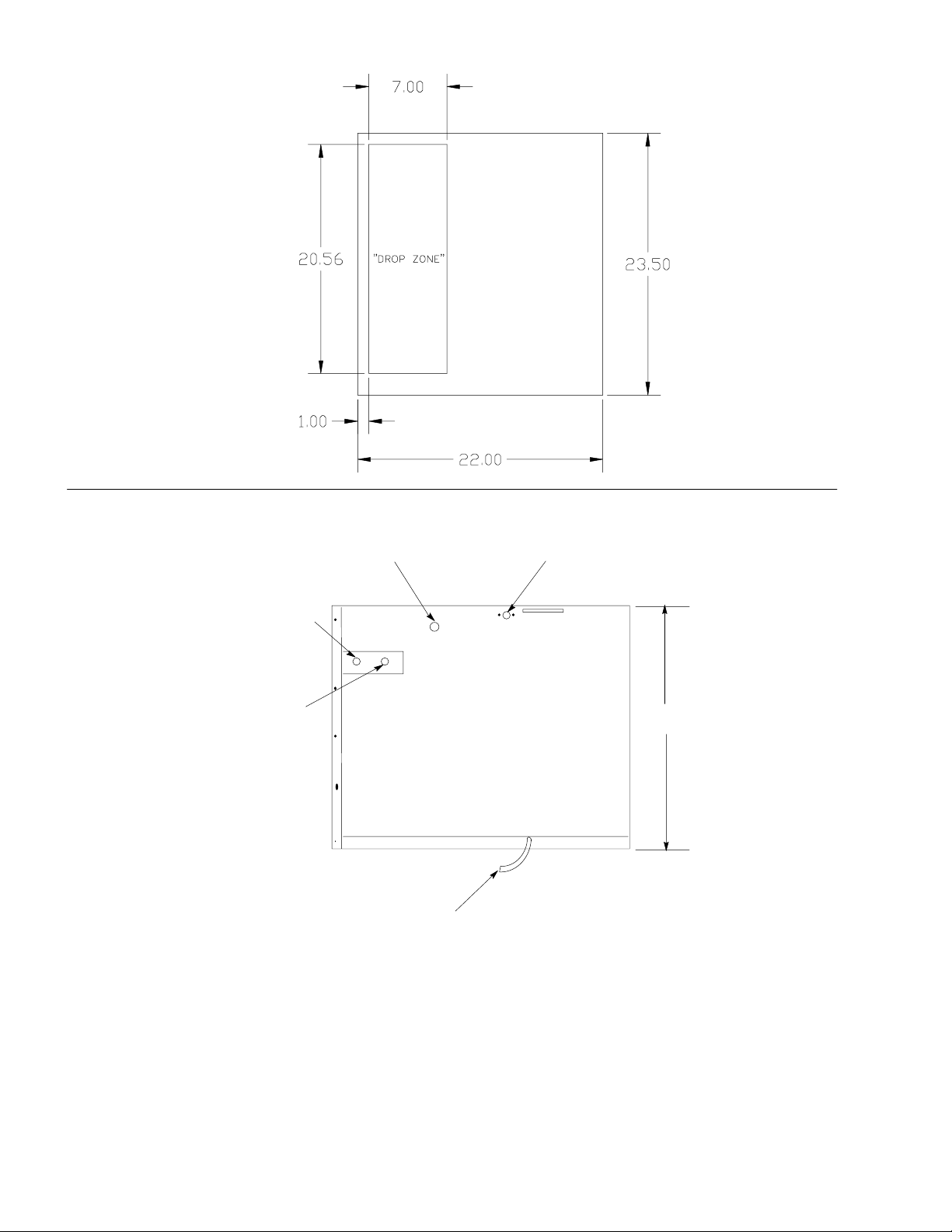
FIGURE 1. ICE–DROP ZONE IRC522
BOTTOM VIEW
FIGURE 2. ELECTRICAL & PLUMBING PLUS AERO–EQUIP CONNECTIONS
ELECTRICAL SERVICE OPENING
(7/8 IN. DIA. HOLE)
1/2 IN. AEROQUIP OUTLET FITTING
3/8 IN. AEROQUIP INLET FITTING
DUMP VALVE DRAIN HOSE
3/8 IN. MALE WATER CONDENSER
OUTLET FITTING
23.00
.56 I. D. BY .66 O.D.
REAR VIEW
630460035
6
Page 10

FIGURE 3. ICE–DROP ZONE IRC530
BOTTOM VIEW
FIGURE 4. ELECTRICAL & PLUMBING PLUS AERO–EQUIP CONNECTIONS
ELECTRICAL SERVICE OPENING
(7/8 IN. DIA. HOLE)
1/2 IN. AEROQUIP OUTLET FITTING
3/8 IN. AEROQUIP INLET FITTING
DUMP VALVE DRAIN HOSE
3/8 IN. MALE WATER CONDENSER
OUTLET FITTING
23.00
.56 I. D. BY .66 O.D.
REAR VIEW
7
630460035
Page 11

INSTALLATION INSTRUCTIONS REMOTE CONDENSERS
UNIT
BRACE
LEG
1/4-20 SCREW
LEG
1. Follow the standard installation instructions supplied with cuber. Do not hook cuber into the power source
until the remote condenser and line set installation is complete.
2. Assembly of remote condenser (see drawing):
A. Assemble legs to base panel. Install leg supports on legs.
B. Locate the remote condenser in a well–ventilated area on the roof away from other refrigeration equip-
ment’s condenser discharge air flow.
C. Use the mounting holes provided to secure the remote condenser to the roof. Seal over heads of bolts
or fasteners with tar or pitch to prevent entrance of moisture.
REMOTE CONDENSER
LEG SUPPORT
LEG
3. Remote condenser electrical hook-up:
A. Connect remote condenser to a power source (115VAC, 60 HZ) separate from the cuber. An external
disconnect switch must be used.
B. Make sure the electrical connections follow all local and
national codes.
NOTE: DO NOT turn condenser on until cuber install and refrigerant line connections are complete!
A.. Never wire condenser into cuber section. The condenser is an independent electrical connection.
B.. Fan motor will not start until pressure rises to 205 PSIG [14.07 Bars] closing fan cycling switch.
C.. The condenser fan may cycle off during the harvest cycle – this would be normal.
NOTE: Installing an IMI Cornelius remote cuber with other than an IMI Cornelius remote condenser
and line set may be reason to void the cuber warranty.
630460035
8
Page 12

4. Each condenser and cuber is connected with two (2) *pre-charged lines.
A. The pre-charged lines are ordered separately from the condenser to suit each individual application.
B. The pre-charged line lengths are 20 feet [6.096 meters], 35 feet [10.66 meters] and 55 feet [16.76 me-
ters].
NOTE (Pre-charged is defined as a vapor holding charge – not a portion of the system charge.)
5. Installation of line kits (see drawing). Remove the tubing from the carton. Carefully uncoil the lines so the
tubing doesn’t become kinked, and route lines to cuber and condenser.
6. Keep line-set as short as possible. Place a 3-foot service loop behind cuber to allow for rear service
should it ever be required.
LIQUID
REFRIGERANT
LINE
DISCHARGE
LINE
CORRECT
9
630460035
Page 13

REMOTE CONDENSER LOCATION
1. Physical Line-Set Length: 55 Ft. Maximum [16.764 meters]
The ice machine compressor must have the proper oil return. Line-set rises, drop, or horizontal runs great-
er than the maximum distance allowed will exceed the compressor start-up and pumping design limits, and
will result in poor oil return to the compressor.
Line-Set Rise: 35 Ft. Maximum [10.66 meters]
Line-Set Drop: 15 Ft. Maximum [4.57 meters]
2. Calculated Line-Set Distance: 100 Ft. [30.48 meters]
To prevent the combination of rises, drops and horizontal runs exceeding the compressor start-up and
pumping design limit, the following calculations should be made:
NOTE: Max. line–set for IMI Cornelius cubers is 55 ft. Do not confuse line length with calculated line
distance
A - (RISE) CONDENSER HIGHER THAN EVAP.
MAX. 35 FT.
B - LINE LENGTH 15 FT.: EXAMPLE
B - LINE LENGTH 35 FT.: EXAMPLE
C - (DROP) CONDENSER LOWER THAN EVAP. 15 FT.: MAX.
A
B
Maximum Line-Set Distance Formula
A. Measured rise x 1.7= Calculated Rise 35 ft. Max) [10.66 meters]
B. Measured drop x 6.6= Calculated Drop 15 ft. Max) [4.57 meters]
C. Measured Horizontal Distance = actual measurement.
D. Total Calculated Distance (A+B+C)=Total Calculated Distance (100 ft. Max.) [30.48 meters]
Examples:
a. Insert measured rise (R) into the formula and multiply it by 1.7 to get a calculated rise.
B
C
630460035
example: A condenser located 15 ft. [4.572 meters] above the ice machine has a 25.5 ft. [8.874
meters] calculated total (15 ft. x 1.7 = 25.5).
H
AIR
FLOW
R
b. Insert measured drop (D) into formula and multiply by 6.6 to get a calculated drop.
example: A condenser located 8 ft. [2.438 meters] below the ice machine has a 52.8 ft. [16.093
meters] calculated total (8 ft. x 6.6 = 52.8 ft.).
H
COMBINATION OF
DROP(S)
WITH HORIZONTAL
D
AIR
FLOW
10
Page 14

c. Insert measured horizontal distance into formula. No calculation is necessary. (6 ft.) [1.828 me-
ters].
d. Add the calculated rise, calculated drop, and horizontal distance together to get the total calcu-
lated distance (25.5 + 52.8 + 6) equals 84.3 ft. [25.694 meters]. If 100 ft. [30.48 meters] total calculated distance is exceeded, the condenser must be moved to a new location which permits
proper equipment operation.
H
COMBINATION OF RISE AND
DROP(S)WITH HORIZONTAL
R
D
AIR
FLOW
CAUTION: If a line-set rise is followed by a line-set drop, a second line-set rise cannot be
made. Or If a line-set drop is followed by a line-set rise, a second line-set drop cannot be
made.
3. Lengthening or Reducing the Line-Set Lengths
In most cases, by routing the line-set properly, shortening will not be necessary (refer to illustration). How-
ever, when shortening or lengthening is required, do so before connecting the line-set to the ice machine or
the remote condenser. This prevents the loss of refrigerant from the ice machine or the condenser.
The quick connect fittings on the line-sets are equipped with Schrader Valves. Use these valves to recover
any vapor charge from the line-set. When lengthening or shortening lines, apply good refrigeration practices and insulate new tubing. Do not change the tube sizes. Evacuate the lines and place approximately 5
oz. of vapor refrigerant charge in each line.
SCHRADER
VALVE
PARENT METAL SEAL
INTERMEDIATE SEAL
4. Connection of Line-Set
A. Remove the plastic caps from the line-set, the condenser, and the ice machine.
B. Apply refrigeration oil to the threads on the quick connect couplers before connecting them to the con-
denser.
C. Carefully thread the female fitting onto the condenser or ice machine by hand.
D. Using the proper size wrench, tighten the couplings until they bottom out. Turn an additional 1/4 turn
to ensure proper brass-to-brass seating.
E. Check all fittings for leaks.
5. Final Installation:
A. Remove grill from the right-hand side panel of cuber.
B. Turn service port on receiver tank to open position releasing refrigerant to the balance of the system.
C. Leak check line-set connections at cuber and condenser.
D. Replace grill.
E. Connect cuber to power source.
F. Make sure electrical connections follow all local and national codes.
6. Start Up:
11
630460035
Page 15

A. Use standard procedures from cuber installation instructions.
B. After the cuber is running, check the remote condenser and verify that the condenser fan is running.
CAUTION: Once the refrigerant lines are connected, the seal is broken in the fittings. If the
lines are removed or loosened from the cuber or remote condenser, the refrigerant charge
will be discharged to the atmosphere. DISCHARGING TO THE ATMOSPHERE IS IN
VIOLATION OF THE CLEAN AIR ACT OF JULY, 1992.
HEAD PRESSURE CONTROL [HEADMASTER]
discharge
above 70°F
normal
receiver
discharge
condenser
condenser
below 70°F by-pass
receiver
The Cornelius “I” series remote systems use an Alco Head Pressure Control, normally referred to as a headmaster. This control is mounted in the remote condenser with a fan cycling control switch. Using both these
controls gives the system positive operation under a wide range of condensing temperatures.
The cycling control starts the fan at 270 PSI and stops it at 205 PSI allowing a positive efficient operation at the
high temperature operating ranges.
The headmaster controls the operation when the condensing temperature drops below 70°F. The “I” series refrigerant charge is HP - 62 [R - 404A] and the headmaster dome charge setting is 200 PSI of nitrogen pressure
making it stable under the low temperature operating range down to - 20°F.
The normal flow pattern through the headmaster is from the condenser port to the receiver port. When this flow
pattern is unable to maintain a receiver outlet pressure equal to or above the dome pressure setting of the
valve, the dome pressure will force the valve portage to change closing the condenser port and opening the bypass port from the compressor discharge line. This allows the high pressure vapor from the discharge port to
“buck” the receiver pressure back up. With the condenser port closed, the refrigerant is backed up in the condenser, basically reducing the condenser size, assisting in maintaining the discharge portage flow and increasing the head pressure.
Remember, sense of touch to the lines of the headmaster will determine the flow path the headmaster is in,
condenser to receive, or bypass to receiver.
High side gauge installed at the receiver outlet valve will determine if the headmaster is functioning to maintain
the proper operating pressure.
In the event the control appears to be “stuck in bypass”, the pressure drop across the headmaster must be
measured. With a gauge installed at the receiver outlet valve and the high side service valve, the pressure difference at these two points must be less than the 15 PSI. The three most common causes of an excessive
pressure drop are shortage of refrigerant, kinked remote lines, and excessive line length.
Eliminate refrigerant shortage first. Add refrigerant in two-pound increments (not to exceed six pounds) to
determine if it corrects the pressure drop. If pressure drop is not corrected, inspect line set for sharp bends or
kinks and correct as required. If adding refrigerant does not correct continued (bypass) condition and line set is
not damaged, replace headmaster.
630460035
12
Page 16

REMOTE SYSTEM EVACUATION/RE-CHARGE
All field repairs to the sealed system must start with a total discharge of the system following the requirements
of the Clean Air Act of July, 1992.
Proper evacuation of the total remote system will require a three (3) point hook-up of your manifold and hose
set, (see drawing):
Point #1 - Cuber receiver outlet valve
Point #2 - Cuber high side service valve
Point #3 - Cuber low side service valve
Evacuation:
1. With cuber power supply turned “OFF” disconnect and insulate all 3 compressor leads at the compressor.
Turn power supply on, place power switch in the “on” position. This will energize (open) the Liquid Line solenoid allowing evacuation of the Liquid Line between the solenoid and the expansion valve(s).
2. Evacuate system to 200/250 microns or less. At this point, there should be a holding test of five(5) minutes.
You may expect a slight loss of vacuum as normal. A rapid rise to normal atmospheric pressure indicates
moisture still present in the system. On a “wet” system, it will prove beneficial to use heat lamps to warm
the compressor dome and evaporator surface during evacuation.
3. Turn cuber power switch OFF. Reconnect compressor leads.
4. *After proper evacuation hold test has been performed, the refrigerant charge should be “dumped” into the
receiver until the pressure equalizes, stopping the flow. Do not try to throttle the refrigerant flow. Doing so
will allow system pressure to balance too soon. The high-side service valve should be closed and the balance of the charge fed slowly through the suction side service valve with the compressor operational. Control the feed rate at no faster than four (4) ounces [113.g] per minute to ensure the compressor oil does not
become too saturated with refrigerant resulting in a loss of compressor lubrication.
5. All refrigerant re-charging must be weighed into the system, utilizing an electronic charging scale. DO NOT
attempt to recharge the system by sight glass, system pressure, amperage, frost line or sweat patterns.
6. Always leak check entire system after recharge.
OPEN
RECEIVER
OPEN
RECEIVER
OUTLET
VALVE
CAUTION: Before programming the electronic scales to “dump” the charge, de-energize
the liquid line solenoid, close the shut-off valve on vacuum pump and low side of the
manifold set.
EVACUATION
MANIFOLD SET
OPEN
OPEN
CHARGING
CYLINDER
OPEN
HIGH SIDE
SERVICE
VALVE
SERVICE
VALVE
CLOSED
LOW
SIDE
1ST STAGE CHARGING
OPEN
RECEIVER
OPEN
RECEIVER
OUTLET
VALVE
CLOSED
MANIFOLD SET
CLOSED
CLOSED
CHARGING
HIGH SIDE
SERVICE
VALVE
LOW
SIDE
SERVICE
VALVE
OPEN
CYLINDER
CLOSED
2ND STAGE CHARGING
COMPRESSOR OPERATING
MANIFOLD SET
CLOSED
RECEIVER
RECEIVER
OUTLET
VALVE
CLOSED
OPEN
CLOSED
CHARGING
CYLINDER
HIGH SIDE
SERVICE
SERVICE
VALVE
OPEN
VALVE
LOW
SIDE
VACUUM
PUMP
CLOSED
ELECTRONIC
SCALE
VACUUM
PUMP
OPEN
ELECTRONIC
13
SCALE
VACUUM
PUMP
OPEN
ELECTRONIC
SCALE
630460035
Page 17

START-UP AND CHECK OUT
1. Turn the Cuber’s power switch to the clean (pump only) position. The water pump only should be opera-
tional. Wipe the top extrusion briskly with a ScotchBrite pad. Check for an even, steady flow of water over
evaporator top extrusion and down over evaporator surface. Check that all ports of the water distribution
tube are open for even water discharge. The water pan should refill and the float should stop the incoming
water supply.
NOTE: Should service be required on the float valve or strainer, turn the water supply off, loosen the
float, hold down nut and remove the float and strainer as an assembly for ease of service.
2. Place the Cuber’s power switch in the ON position. After a
2-second delay the compressor will start. The condenser fan will operate when the condenser sensor signals the circuit board its temperature is 100_F (38_C). The water pump will operate when the evaporator
cools to 25_F (–3.9_C). Depress the manual harvest switch (on the circuit board). The fan motor will stop
and the water dump valve will open. In 3 seconds the hot gas solenoid will open and 15 seconds after depressing the manual harvest switch, the water pump and dump valve will close terminating the dump cycle.
3. Hold the water curtain open for a maximum of 30 seconds; the Cuber should shut down. Release the water
curtain(s). When the curtain(s) closes, there will be a 2-second delay, then the compressor will start and
the start-up process should begin for the next
ice-making mode.
4. If all Cuber operation is as stated, allow product to operate and produce one slab of ice, then discard the
ice. Allow the Cuber to continue operation to fill the storage bin.
Power Switch
630460035
14
Page 18

OWNER -OPERATOR
The installation is not complete until you are sure the owner-operator understands the cuber operation and his
or her responsibility of preventative maintenance.
Does the owner-operator know:
1. Location of electrical disconnect switch and water shut-off valves?
2. How to start and/or shut down the product, clean and sanitize it?
3. Bin full operation and reset operation of high pressure cutout (water-cooled and remote products only)?
4. How to clean the condenser and fan blade?
5. Whom to call for product information and/or service?
CLEANING PROCEDURES
Approved ice machine cleaners by brand names:
S Lime–A–Way
S Calgon Nickel Safe (green color only)
NOTE: All ice machine cleaners labeled safe for nickel ARE NOT the brand CALGON NICKEL SAFE.
CAUTION: Ice machine cleaners are acidic-based chemicals. Before beginning any
cleaning of the cuber, the ice in the storage bin or dispenser must be removed.
WARNING: When using any chemical, rubber gloves and eye protection should be worn.
PREP – CLEANING
Use full-strength ice machine cleaner on a coarse-surface cloth material (such as terry cloth) and wipe down the
inside wall of the evaporator area, the water pan, the water curtain and evaporator plastic extrusions. If the water distributor tube has heavy scale build-up, remove and soak it in full-strength ice machine cleaner (or exchange the tube and clean the scaled tube at a later date).
Cleaning the Water System and Evaporator
Power Switch
1. Set the switch to Clean and allow any ice on the evaporator to release and melt away.
2. Remove all ice from the storage bin.
3. Remove the water curtain(s), pour 1/2 oz. of ice machine cleaner down the rear key-slot openings. The
cleaner will drain into the water pan.
4. Return the water curtain(s) to their proper operating positions.
5. Add 3 oz. for a single evaporator, or 5 oz. for a dual evaporator of “Calgon Nickel Safe” or “Lime-A-Way”
ice machine cleaner directly into the water pan. The float will balance with inlet water. Set switch to
CLEAN, circulate for a maximum of 15 minutes.
15
630460035
Page 19

6. Depress and hold the dump switch to allow the cleaner to drain away.
7. Fill the water pan with clean fresh water, circulate for approximately 3 minutes. Depress and hold the
DUMP switch and allow the water to drain away. Repeat the procedure 3 times.
8. After third rinse cycle, place product power switch in ice position. Allow Cuber to produce one slab of ice –
DISCARD THE ICE.
9. When the clean cycle is complete, return cuber to normal operating mode.
NOTE: Please Take Note of the Following:
S Ice machines should only be cleaned when needed, not by a timed schedule of every 60 days, etc.
S Should your ice machine require cleaning more than twice a year, consult your distributor or dealer about
proper water treatment.
SANITIZING PROCEDURES
NOTE: To be performed only after cleaning the ice machine:
1. Add 1/4 ounce (7.08 g) sodium hypochlorite solution (common liquid laundry bleach) to the water pan and
allow the pump to circulate the solution for 5 minutes. You may also use a commercial sanitizer such as
Calgon Ice Machine Sanitizer following the directions on the product label.
2. Turn the Cuber power switch off and depress and hold the dump switch to drain the water pan.
3. To sanitize the bin and other surface areas, use 1 ounce of liquid bleach per gallon of water and wipe all
areas with the solution. Or use a commercial sanitizer.
4. Place the Cuber power switch in the ice position. Discard the first batch of ice produced.
5. Cleaning and sanitizing are now complete. Cuber may be returned to normal service.
IMPORTANT: Service personnel are held responsible for ALL ASPECTS OF THE CLEAN AIR ACT OF
JULY 1992.
REFRIGERANT DEFINITIONS
(ASHRAE 3–1990)
RECOVERY
To remove refrigerant in any condition from a system and store it in an external container without
necessarily testing or processing it in any way.
RECYCLING
To clean refrigerant for reuse by oil separation and single or multiple passes through devices,
such as replaceable filter–driers, which reduce moisture, acitity, and particulate matter. This term
usually applies to procedures implemented at the field job site or at a local service shop.
RECLAIM
Tp reprocess refrigerant to new product specifications by means which may include distillation.
Will require chemical analysis of the refrigerant to determine that appropriate product specifications are met. This term usually implies the use of processes or procedures available only at a
reprocessing or manufacturing facility.
NOTES REGARDING RECLAIM:
“New product specification” currently means ARI standard 700–878. Note that chemical analysis
is required to assure that this standard is met.
Chemical analysis is the key requirement to the definition of “Reclaim”. Regardless of the purity
levels reached by a reprocessing method, the refrigerant is not “reclaimed” unless it has been
chemically analyzed and meets ARI standards.
HIGH PRESSURE SAFETY SWITCH
All water-cooled and remote products contain a high pressure safety cut-out switch. The function of this switch
is to shut down the cuber should excessive pressure develop in the high side of the refrigeration system. This
switch will open the power supply at 450 PSI (30.61 BAR) high side pressure. Should this control open, it must
be reset manually and the cause for the increase in pressure determined.
630460035
16
Page 20

ADJUSTING BRIDGE THICKNESS
TOP ROW
3/8I - 5/8I DIMPLE
CENTER
1/8I BRIDGE
BOTTOM 2 ROWS
3/16I - 1/4I BRIDGE
For optimum ice production and maximum cube separation, the ice
connecting the individual cubes should be a minimum of 1/8I (.32cm)
thick at the center area of the ice waffle.
BRIDGE 1/8I (0.32 cm)
It is normal for the ice slab to be slightly thicker at the bottom and taper
off in a slight wedge pattern at the top. The top row of cubes must have
a complete pattern of ice on all four sides and the back wall. Remember, when you operate the product with the panels off during testing the
additional heat at the top of the evaporator will cause thinner ice at the
top than when the panels are in place.
Should a different thickness of the bridge be desired, it will be required
to adjust the ice thickness “POT”, located on the circuit board, as follows:
1. Thinner Bridge – turn the ice thickness “pot” adjustment screw
CW one full turn. Allow two cycles before determining if
additional adjustments are required.
2. Thicker Bridge – turn the ice thickness “pot” adjusting screw CCW
one full turn. Allow two cycles before determining if additional adjustments are required.
NOTE: Never judge the thickness of the ice from the first batch of the ice produced – the first cycle is
a balance cycle. Always wait for the second cycle before making any adjustments.
TOTAL ICE CAPACITY
Ice capacity of any ice maker is affected by many operating conditions, such as water and air temperature and
location factors. Please review the capacity tables in this manual for average 24-hour capacity under various
conditions.
NOTE: All printed capacity ratings are 10% except 50 HZ units. These products have 12% increase
in cycle time and capacity decrease of approximately 17%.
ICE PRODUCTION CHECK
If air cooled, take air temperature at the intake of the condenser, 2I from the condenser fins, and Incoming water temperature at the outlet of the “float” valve.*
Cycle time (CT) = freeze time plus harvest time, in minutes and seconds. 1440 divided by CT = number of
cycles per 24 hours.
Measure weight of ice from one cycle in pounds and fractions of a pound.
EXAMPLE: Weight/cycle x cycles/day = total production/24 hrs. Compare to the production tables.
17
630460035
Page 21

Suction Line Sensor
Bridge thickness pot.
S3-1 S3-2
1 OFF OFF Dump Every Harvest (FACTORY SETTING AS RECEIVED)
2 ON OFF Dump Every Third Harvest
3 OFF ON Dump Every Seventh Harvest
ON
S3–2
S3–1
1
OFF
ON
S3–1
2
3
S3–1
S3–1
S3–2
OFF
ON
S3–2
OFF
ON
S3–2
OFF
ON
4
5
6
SW4
OFF
ON
SW4
OFF
ON
SW4
OFF
Dump Cycle Dip Switch
Water Curtain
Dip Switch
Harvest Voltage Set point pins 2
External Error LED
Connection
Condenser Sensor
and 3 Factory setting @ 1.224 V
RD
Error
Dump
GR
Fan
S3–1
On
S3–2
Off
GR
Comp.
On
Curtain
Selection
Switch
Switches
1 2 3
Off
1
2
Bin
3
Micro Processor
YL
YL
Pump
Gear
Gas
GR
GR
GR
YL
4
In
Stack
Out
Com
SINGLE CURTAIN DUAL CURTAIN FOUR CURTAIN
4 Curtain Switch Connected To Any
Bin Connector (J4–J7) (FACTORY
SETTING AS RECEIVED)
5 Curtain Switch Must Be Connected To
Triac
YL
J4 and J5, J6, J7.
Transformer
6 Curtain Switch Must Be Connected
To J4, J5, J6 and J7)
LED INDICATORS
The LEDs are board circuit indicators. If the LED in the functional board circuit is complete, check component.
Example: Contactor does not energize and LED is “ON”, board circuit is OK. Check contactor, coil, leads, &
connections.
Yellow:
S Evaporator switch(s) (proximity)
Green:
S Water dump valve
S Compressor contactor
S Water Pump
S Hot Gas Valve
S Condenser Fan (cycles on & off with fan) – self contained air cooled only.
Red:
Error in system operation. Product shut down.
630460035
18
Page 22

STATUS INDICATOR
D1-2
3-4 Yellow LED Water Curtain(s)-Dip switch
can be set for 1, 2, or 4 curtain
units
D9 Red LED Error
D12 Green LED Hot Gas Valve(s)
D13 Green LED Condenser Fan
D14 Green LED Water Pump
D15 Green LED Compressor Contactor
D16 Green LED Dump Valve
Water Curtain(s) Open
D1-2 Yellow LED on or curtain(s) Closed.
3-4 off curtain(s) open.
Pre-Chill Mode
D1-2
3-4
D13 Green LED (on or off) Condenser fan, cycles on and off depending upon condenser temperature.
D15 Green LED (on) Contactor closed, compressor active.
Y ellow LED (on) Water Curtain(s) closed.
Ice-Making Mode
D1-2
3-4
D13 Green LED (on or off) Condenser fan, cycles on and off depending upon condenser temperature.
D14 Green LED (on) Water pump active at evaporator temperature of 20_F or lower, except during dump cycle.
D15 Green LED (on) Compressor contactor closed..
Y ellow LED (on) Water Curtain(s) closed.
Harvest Mode
D1-2
3-4
D14 Green LED (on) 15 sec. Water pump active for 15 sec., then deactivate.
D15 Green LED (on) Compressor contactor closed – compressor active.
D16 Green LED (on) 15 sec. Dump valve active 15 sec.
Y ellow LED (on) Water curtain(s) closed.
Error LED
D9 Red LED Turns on when the system is shut down.
D9 Red LED (on) or flashing Assists to indicate where the error may be and or what may have caused the error.
D9 Red LED (on) EVAPORATOR temperature drops below -25_F.
D9 Red LED (on) OPEN THERMISTOR CIRCUIT (Air Cooled only) - Thermistor open/broken wire/poor connector.
D9 Red LED (on) High evaporator temperature: evaporator does not fall below 40_F within 6 minutes into freeze
D9 Red LED Flashing, 1/2
sec. on / 1/2
sec. off
D9 Red LED Flashing, 1/4
sec. on / 1/4
sec. off, 1 sec.
delay then repeat
cycle.
High temperature shutdown - condenser temperature exceeds 150_F +2, -6_F.
Low temperature shutdown - condenser temperature less than 36_F +2, -6_F.
19
630460035
Page 23

COMPONENT FUNCTION
SENSORS
Suction line sensor (BLUE) is a thermistor rated 1k ohm at room temperature.
S Suction line sensor signals the circuit board the suction line temperature, to control ice bridge thickness.
Also the sensor serves as suction line high temperature signal (Cuber has 6 minutes to reduce suction line
temperature to 40°F (4.4°C) in the freeze mode). The red “Error LED” will be steady on. Should this time
frame not be met, product is functionally inoperative during this safety shut down. Reset procedure must be
performed to restart product operation.
RESET OPERATION
When Cuber is functionally shut down and red “Error LED” is operational, the Cuber power switch must be
turned off for 5 seconds and returned to the ON position to reset the circuit board and allow the Cuber to restart
operation.
Evaporator Switches
Proximity Switches are half mounted to the water curtain, and the other half mounted to the evaporator side rail.
Switch Notes
1. Manually holding the curtain open during freeze mode will shut the Cuber down in 5 seconds.
2. During harvest cycle, if curtain is open for 10 seconds, the water pump will stop. The compressor will operate for 20 additional seconds before Cuber shut down takes place. When the water curtain is closed, the
Cuber will begin the normal start-up process.
3. In single evaporator machines, the proximity switch connection must be on the top (RH) connection on the
circuit board.
4. In dual evaporator machines, both RH and LH switches must open and reset to start the next freeze mode.
Harvest Safety Termination
After 4 minutes in the harvest mode, the safety timer in the circuit board will terminate the harvest mode and
place the Cuber back into a freeze mode. This safety cycle will protect the evaporator, etc. should the product
fail to terminate the harvest mode for any reason.
VOLTAGE CHECKS
Evaporator Proximity Switch
Turn Cuber power switch OFF. Disconnect proximity switch plug(s) from the circuit board. Use a digital multimeter set for D.C. Voltage; turn power switch ON, connect leads of meter across the top two terminal pins on the
board, (for the switch being tested), meter should read 4.5 / 5 VDC output voltage. If not replace the circuit
board.
STACKING CABLE
When stacking the “I” series cuber the connecting cable (connecting the two (2) circuit boards) will allow: the
bottom Unit to shut off on the full bin signal (or any error code), the top Unit will then finish the cycle it is in and
shut down. The “I” series should never be stacked more than two high.
630460035
20
Page 24

SENSOR [THERMISTOR] DIAGNOSIS
Sensors
Condenser or suction line – Turn Cuber power switch OFF. Disconnect sensor plug from board. Use digital
multimeter set for D.C. Voltage. Turn power switch ON. Connect leads of meter across the two pins of the sensor being checked. Meter should read 4.5 / 5 VDC output voltage from the board. If voltage is not correct, replace the circuit board.
Should the cuber operation indicate there may be a fault in the sensor [thermistor] or the control board circuit proceed as follows.
1. Using a good multimeter, check the control board sensor output voltage.
2. If voltage checks are correct do the following:
A. Disconnect the suction line sensor (brown or gray lead) from the control board.
B. Install the special test cord* to the control board and reinstall the sensor to the test cord terminals.
C. Connect the multimeter (set on VDC - milli-volts) to the test cord leads.
D. Operate the cuber in the freeze cycle.
3. As the suction line temperature decreases the milli-volt reading will increase.
4. Sensor Shorted – milli-volt reading will cease to increase and will remain steady indicating a shorted sensor.
5. Sensor Open – The voltage reading will indicate the control aboard output voltage of 4.5 / 5 VDC.
6. Should step 4 or 5 occur during this test, the sensor will require replacement.
* Special test cord, part # 164984009, may be ordered through the Service Department.
7. Condenser Sensor (white leads) – self-contained air-cooled only – water cooled and remote systems
use a resistor plug on the control board.
Complete the sensor and multimeter connections as described in
2- B, C, D
8. Shorted sensor – a steady low milli-volt reading will be recorded. The reading will not change.
9. Open sensor – the multimeter will record control board output voltage of 4.5 / 5 VDC.
10. Should sensor (thermistor) pass the voltage test proceed to the control board diagnosis for LED sequence
(see page 19).
NOTE: The sensor controls the condenser fan cycling from 88/100 degree Fahrenheit. Thus any
defects in the condenser circuit will effect the fan cycling rate.
THERMOSTATIC EXPANSION VALVES
The following suggestions for diagnosis of automatic Thermostatic Expansion Valve (TXV) are given with the
understanding that the following have been checked and are correct and/or have been corrected prior to proceeding.
1. The condenser and fan blade are clean and have proper operating conditions.
2. Water supply to the product is correct and flow over the evaporator is correct.
3. Cuber refrigerant charge is correct.
4. TXV sensing bulb is properly located and secured to the suction line and correctly insulated.
5. Hot gas valve(s) are not leaking and/or seeping through.
21
630460035
Page 25

GRN
BLK
CO 450 PSIG
MANUAL RESET
HIGH PRESSURE
CONTROL
CLN
OFF
UNIT
SWITCH
ON
BLK
BLK
CONTACTOR
BLU
BLK
CONDENSATION
FAN
BRN
BLU
BLK
YEL
BLU
BRN
BLK
BRN
WHT
WATER
SWITCH
COMPRESSOR
COMPRESSOR
BLK
DUMP
BLU
EXTERNAL
OVERLOAD
COMPRESSOR
RUN
CAPACITOR
RED
YEL
YEL
LIQUID LINE
SOLENOID
BLK RED
CRANKCASE HEATER
(RC ONLY)
BLK BLK
WHT
BLK
WATER DUMP
VALVE
RED
30mfd
440VAC
POTENTIAL
START
RELAY
COMPRESSOR
START
CAPACITOR
72-86mfd
330VAC
WHT
WHT
WHT
BLU
RED
WHT
HOT GAS
SOLENOID
WHT
WATER PUMP
WHT
WHT
630460035
FIGURE 5. WIRING DIAGRAM IRC522 AND IRC530
22
Page 26

WIRE
NUT
BK
FAN CYCLING
PRESSURE
SWITCH
M
CONDENSOR
FAN MOTOR
BK
BK
TERMINAL
BLOCK
115VOLTS 60 HZ
CR500
REMOTE CONDENSER
Part No. 630300193 Rev. A
GR
Artwork 50962
FIGURE 6. WIRING DIAGRAM REMOTE CONDENSER CR500
23
ILL372
630460035
Page 27

630460035
24
S
WATER
DUMP VALVE
WATER PUMP
WATER
FLOAT
VALVE
EVAPORATOR
HOT GAS
SOLENOID
VALVE
S
THERMOSTATIC
EXPANSION VALVE
FAN MOTOR
LIQUID SOLENOID VALVE
HEAT EXCHANGER
HIGH SIDE
SERVICE
VALVE
FAN BLADES
LOW SIDE
SERVICE
REMOTE CONDENSER
VALVE
S
FILTER/DRIER
HIGH PRESSURE
CUTOUT SWITCH
FAN CYCLING SWITCH
PRESSURE
COUPLINGS
VALVES
RECEIVER
SERVICE VALVE
HEAD
CONTROL
COMPRESSOR
FIGURE 7. REFRIGERATION AND WATER SYSTEMS IRC522 AND IRC530
CHECK
VALVE
Page 28

AVERAGE OPERATING CHARACTERISTICS
IRC522/IRC530
IP Units
FREEZE CYCLE HARVEST CYCLE
AVERAGE
AMBIENT
TEMP
_F
70 50 220 38 12.5 155 95 1.0 5.1 540
80 70 250 42 14.6 175 111 0.9 4.8 450
90 70 275 41 17.4 195 120 0.7 5.1 405
90 80 290 45 17.9 200 120 0.6 5.0 387
100 70 320 46 20.9 220 120 0.6 5.2 350
WATER
TEMP
_F
HEAD
PRESSURE
Psig
SUCTION
PRESSURE
Psig
CYCLE
TIME
Min:Sec
HEAD
PRESSURE
Psig
SUCTION
PRESSURE
Psig
CYCLE
TIME
Min:Sec
ICE
WEIGHT
lb/Cycle
AVERAGE
ICE
WEIGHT
lb/Day
25
AMBIENT
630460035
SI Units
FREEZE CYCLE HARVEST CYCLE
WATER
TEMP
_C
21 10 1517 262 12.5 1069 655 1.0 2.3 245
27 21 1724 290 14.6 1207 765 0.9 2.2 204
32 21 1896 283 17.4 1344 827 0.7 2.3 184
32 27 1999 310 17.9 1379 827 0.6 2.3 176
38 21 2206 317 20.9 1517 827 0.6 2.4 159
TEMP
_C
HEAD
PRESSURE
kPa
SUCTION
PRESSURE
kPa
CYCLE
TIME
Min:Sec
HEAD
PRESSURE
kPa
SUCTION
PRESSURE
kPa
CYCLE
TIME
Min:Sec
AVERAGE
ICE
WEIGHT
kg/Cycle
AVERAGE
WEIGHT
ICE
kg/Day
Page 29

WARRANTY
IMI Cornelius Inc. warrants that all equipment and parts are free from defects in material and workmanship under normal use and service. For a copy of the warranty applicable to your Cornelius, Remcor or
Wilshire product, in your country, please write, fax or telephone the IMI Cornelius office nearest you.
Please provide the equipment model number, serial number and the date of purchase.
IMI Cornelius Offices
AUSTRALIA D P.O. 210, D RIVERWOOD, D NSW 2210, AUSTRALIA D (61) 2 533 3122 D FAX (61) 2 534 2166
D AM LANGEN FELDE 32 D A-1222 D VIENNA, AUSTRIA D (43) 1 233 520 D FAX (43) 1-2335-2930
AUSTRIA
D BOSKAPELLEI 122 D B-2930 BRAASCHAAT, BELGIUM D (32) 3 664 0552 D FAX (32) 3 665 2307
BELGIUM
D RUA ITAOCARA 97 D TOMAS COELHO D RIO DE JANEIRO, BRAZIL D (55) 21 591 7150 D FAX (55) 21 593 1829
BRAZIL
ENGLAND
D TYTHING ROAD ALCESTER D WARWICKSHIRE, B49 6 EU, ENGLAND D (44) 789 763 101 D FAX (44) 789 763 644
D 71 ROUTE DE ST. DENIS D F-95170 DEUIL LA BARRE D PARIS, FRANCE D (33) 1 34 28 6200 D FAX (33) 1 34 28 6201
FRANCE
GERMANY
GREECE
HONG
ITALY
NEW
SINGAPORE
SPAIN
USA
D CARL LEVERKUS STRASSE 15 D D-4018 LANGENFELD, GERMANY D (49) 2173 7930 D FAX (49) 2173 77 438
D 488 MESSOGION AVENUE D AGIA PARASKEVI D 153 42 D ATHENS, GREECE D (30) 1 600 1073 D FAX (30) 1 601 2491
KONG D 1104 TAIKOTSUI CENTRE D 11-15 KOK CHEUNG ST D TAIKOKTSUE, HONG KONG D (852) 789 9882 D FAX (852) 391 6222
D VIA PELLIZZARI 11 D 1-20059 D VIMARCATE, ITALY D (39) 39 608 0817 D FAX (39) 39 608 0814
ZEALAND D 20 LANSFORD CRES. D P.O . BOX 19-044 AVONDALE D AUCKLAND 7, NEW ZEALAND D (64) 9 8200 357 D FAX (64) 9 8200 361
D 16 TUAS STREET D SINGAPORE 2263 D (65) 862 5542 D FAX (65) 862 5604
D POLIGONO INDUSTRAIL D RIERA DEL FONOLLAR D E-08830 SANT BOI DE LLOBREGAT D BARCELONA, SPAIN D (34) 3 640 2839 D FAX (34) 3 654 3379
D ONE CORNELIUS PLACE D ANOKA, M INNE SOTA D (612) 421-6120 D FAX (612) 422-3255
LD004
4/21/98
26
630460035
Page 30

IMI CORNELIUS INC.
CORPORATE HEADQUARTERS:
One Cornelius Place
Anoka, Minnesota 55303-6234
(6763) 421-6120
(800) 238-3600
 Loading...