

Page 1
IMI CORNELIUS INC One Cornelius Place Anoka, MN 55303-6234
Telephone (800) 238-3600 Facsimile (612) 422-3246
Installation Manual
Glacier
Post-Mix Dispenser
IMPORTANT:
TO THE INSTALLER.
It is the responsibility of
the Installer to ensure that
the water supply to the
dispensing equipment is
provided with protection
against backflow by an air
gap as defined in
ANSI/ASME A112.
1.2-1979; or an approved
vacuum breaker or other
such method as proved
effective by test.
Water pipe connections
and fixtures directly
connected to a potable
water supply shall be
sized, installed, and
maintained according to
Federal, State, and Local
codes.
Part No. 560003094
March 10, 1998
Control Code A
THIS DOCUMENT CONTAINS IMPORTANT INFORMATION
This Manual must be read and understood before installing or operating this equipment
IMI CORNELIUS INC; 1998
PRINTED IN U.S.A
Page 2

TABLE OF CONTENTS
GENERAL INFORMATION 1. . . . . . . . . . . . . . . . . . . . . . . . . . . . . . . . . . . . . . . . . . . . . . . . . .
SAFETY INFORMATION 1. . . . . . . . . . . . . . . . . . . . . . . . . . . . . . . . . . . . . . . . . . . . . . .
RECOGNIZE SAFETY INFORMATION 1. . . . . . . . . . . . . . . . . . . . . . . . . . . . . . .
UNDERSTAND SIGNAL WORDS 1. . . . . . . . . . . . . . . . . . . . . . . . . . . . . . . . . . . .
FOLLOW SAFETY INSTRUCTIONS 1. . . . . . . . . . . . . . . . . . . . . . . . . . . . . . . . .
CLAIMS INSTRUCTIONS 1. . . . . . . . . . . . . . . . . . . . . . . . . . . . . . . . . . . . . . . . . .
WARRANTY REFERENCE INFORMATION 1. . . . . . . . . . . . . . . . . . . . . . . . . . .
UNIT DESCRIPTION 3. . . . . . . . . . . . . . . . . . . . . . . . . . . . . . . . . . . . . . . . . . . . . . .
THEORY OF OPERATION 4. . . . . . . . . . . . . . . . . . . . . . . . . . . . . . . . . . . . . . . . . . . . . .
UNITS WITH INTEGRAL (BUILT-IN) CARBONATORS 4. . . . . . . . . . . . . . . . .
UNITS WITH INTEGRAL (BUILT-IN) CARBONATORS AND SYRUP
PUMPS 4. . . . . . . . . . . . . . . . . . . . . . . . . . . . . . . . . . . . . . . . . . . . . . . . . . . . . . . . . .
UNITS WITH 3–2–1 COIL CONFIGURATIONS (REQUIRING CONNECTION TO
REMOTE CARBONATORS) 4. . . . . . . . . . . . . . . . . . . . . . . . . . . . . . . . . . . . . . . . . . . . .
OPERATING CONTROLS 6. . . . . . . . . . . . . . . . . . . . . . . . . . . . . . . . . . . . . . . . . . . . . .
INSTALLATION 13. . . . . . . . . . . . . . . . . . . . . . . . . . . . . . . . . . . . . . . . . . . . . . . . . . . . . . . . . . . .
LOOSE-SHIPPED PARTS 13. . . . . . . . . . . . . . . . . . . . . . . . . . . . . . . . . . . . . . . . . . . . . .
IDENTIFICATION OF LOOSED-SHIPPED PARTS 13. . . . . . . . . . . . . . . . . . . . . . . . .
INSTALLATION 13. . . . . . . . . . . . . . . . . . . . . . . . . . . . . . . . . . . . . . . . . . . . . . . . . . . . . . . .
SELECTING LOCATION 13. . . . . . . . . . . . . . . . . . . . . . . . . . . . . . . . . . . . . . . . . . .
SEALING UNIT TO COUNTERTOP 14. . . . . . . . . . . . . . . . . . . . . . . . . . . . . . . . . .
SELECTING SLEEP MODE OPTIONS (UNITS WITH INTEGRAL
CARBONATORS) 15. . . . . . . . . . . . . . . . . . . . . . . . . . . . . . . . . . . . . . . . . . . . . . . . . .
FILL WATER TANK AND START REFRIGERATION SYSTEM 16. . . . . . . . . . .
CONNECTING SYRUP TUBING TO UNIT 17. . . . . . . . . . . . . . . . . . . . . . . . . . . .
CONNECTING CO2 AND PLAIN WATER SOURCES 18. . . . . . . . . . . . . . . . . .
CONNECTING CARBONATED AND PLAIN WATER SOURCES TO 3–2–1
COIL CONFIGURATION REMOTE CARBONATOR UNIT 19. . . . . . . . . . . . . . .
CONNECTING DRIP TRAY DRAIN HOSE 19. . . . . . . . . . . . . . . . . . . . . . . . . . . .
PREPARATION FOR OPERATION 21. . . . . . . . . . . . . . . . . . . . . . . . . . . . . . . . . . . . . . . . . . .
Page
OPENING THE CO2 CYLINDER SHUTOFF VALVE AND LEAK CHECKING 21. .
ACTIVATING THE CARBONATOR 21. . . . . . . . . . . . . . . . . . . . . . . . . . . . . . . . . . . . . . .
UNIT WITH INTEGRAL (BUILT-IN) CARBONATOR AND WITHOUT
BUILT-IN SYRUP PUMPS. 21. . . . . . . . . . . . . . . . . . . . . . . . . . . . . . . . . . . . . . . . . .
UNIT WITH INTEGRAL (BUILT-IN) CARBONATOR AND WITH BUILT-IN
SYRUP PUMPS. 22. . . . . . . . . . . . . . . . . . . . . . . . . . . . . . . . . . . . . . . . . . . . . . . . . .
UNIT REQUIRING CONNECTION TO A REMOTE CARBONATOR. 22. . . . .
ADJUSTING SUGAR SYRUP TANKS CO2 REGULATOR 23. . . . . . . . . . . . . . . . . . .
ADJUSTING DIET SYRUP TANK CO2 REGULATOR 23. . . . . . . . . . . . . . . . . .
ADJUSTING SYRUP PUMPS CO2 REGULATOR (UNITS WITH INTEGRAL
BUILT-IN CARBONATOR AND BUILT-IN SYRUP PUMPS) 23. . . . . . . . . . . . . .
MEASURING AND ADJUSTING DISPENSING VALVE CARBONATED
WATER
FLOW RATE 24. . . . . . . . . . . . . . . . . . . . . . . . . . . . . . . . . . . . . . . . . . . . . . . . . . . . . .
ADJUSTING DISPENSING VALVE WATER-TO-SYRUP “RATIO” OF
DISPENSED PRODUCT 24. . . . . . . . . . . . . . . . . . . . . . . . . . . . . . . . . . . . . . . . . . .
i 560003094
Page 3

TABLE OF CONTENTS (cont’d)
TROUBLESHOOTING 27. . . . . . . . . . . . . . . . . . . . . . . . . . . . . . . . . . . . . . . . . . . . . . . . . . . . . .
ADJUSTMENT OF DISPENSING VALVE SYRUP FLOW REGULATOR DOES
NOT INCREASE TO DESIRED WATER -TO-SYRUP “RATIO”.27. . . . . . . . . . . . . .
ADJUSTMENT OF DISPENSING VALVE SYRUP FLOW REGULATOR DOES
NOT DECREASE TO DESIRED WATER -TO-SYRUP “RATIO. 27. . . . . . . . . . . . . .
DISPENSED PRODUCT CARBONATION TOO LOW. 27. . . . . . . . . . . . . . . . . . . . . .
DISPENSED PRODUCT COMES OUT OF DISPENSING VALVE CLEAR BUT
FOAMS IN CUP OR GLASS. 28. . . . . . . . . . . . . . . . . . . . . . . . . . . . . . . . . . . . . . . . . . . .
DISPENSED PRODUCT PRODUCES FOAM AS IT LEAVES DISPENSING
VALVE. 28. . . . . . . . . . . . . . . . . . . . . . . . . . . . . . . . . . . . . . . . . . . . . . . . . . . . . . . . . . . . . . .
NO PRODUCT DISPENSED. 28. . . . . . . . . . . . . . . . . . . . . . . . . . . . . . . . . . . . . . . . . . . .
ONLY CARBONATED WATER DISPENSED. 28. . . . . . . . . . . . . . . . . . . . . . . . . . . . . .
ONLY SYRUP DISPENSED. 29. . . . . . . . . . . . . . . . . . . . . . . . . . . . . . . . . . . . . . . . . . . .
DISPENSED PRODUCT CARBONATION TOO LOW. 29. . . . . . . . . . . . . . . . . . . . . .
NO PRODUCT DISPENSED FROM ALL DISPENSING VALVES. 29. . . . . . . . . . . .
CARBONATOR NOT OPERATING. 30. . . . . . . . . . . . . . . . . . . . . . . . . . . . . . . . . . . . . .
CARBONATOR NOT OPERATING. 30. . . . . . . . . . . . . . . . . . . . . . . . . . . . . . . . . . . . . .
REFRIGERATION COMPRESSOR DOES NOT OPERATE. 30. . . . . . . . . . . . . . . . .
COMPRESSOR WILL NOT STOP AFTER SUFFICIENT ICE BANK IS
PRODUCED. 31. . . . . . . . . . . . . . . . . . . . . . . . . . . . . . . . . . . . . . . . . . . . . . . . . . . . . . . . . .
COMPRESSOR OPERATES CONTINUOUSLY BUT DOES NOT FORM
SUFFICIENT ICE BANK. 31. . . . . . . . . . . . . . . . . . . . . . . . . . . . . . . . . . . . . . . . . . . . . . .
AGITATOR MOTOR NOT OPERATING. 31. . . . . . . . . . . . . . . . . . . . . . . . . . . . . . . . . .
WARRANTY 33. . . . . . . . . . . . . . . . . . . . . . . . . . . . . . . . . . . . . . . . . . . . . . . . . . . . . . . . . . . . . .
Page
LIST OF FIGURES
FIGURE 1. OPTIONAL CONFIGURATIONS 5. . . . . . . . . . . . . . . . . . . . . . . . . . . . . . .
FIGURE 2. PARTS IDENTIFICATION (SIX-FLAVOR UNIT SHOWN) 6. . . . . . . . .
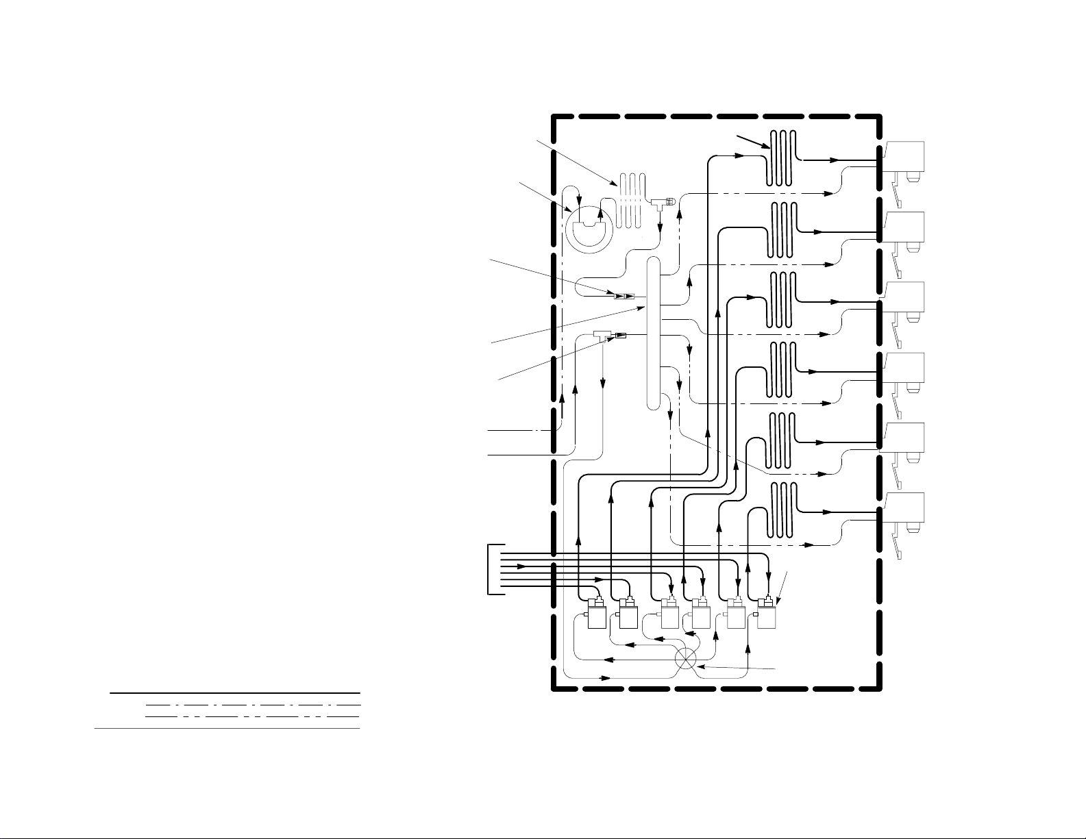
FIGURE 3. FLOW DIAGRAM (SIX-FLAVOR UNIT [P/N 475136102] WITH
INTEGRAL (BUILT-IN) CARBONATOR SHOWN) 7. . . . . . . . . . . . . . . . . . . . . . . . . .
FIGURE 4. FLOW DIAGRAM (SIX-FLAVOR UNIT WITH INTEGRAL (BUILT-IN)
CARBONATOR SHOWN) 8. . . . . . . . . . . . . . . . . . . . . . . . . . . . . . . . . . . . . . . . . . . . . . .
FIGURE 5. FLOW DIAGRAM (SIX-FLAVOR UNIT WITH INTEGRAL CARBONATOR
AND BUILT-IN SYRUP PUMPS) 9. . . . . . . . . . . . . . . . . . . . . . . . . . . . . . . . . . . . . . . . .
FIGURE 6. FLOW DIAGRAM (SIX-FLAVOR UNIT WITH 3–2–1 COIL
CONFIGURATION REQUIRING CONNECTION TO REMOTE CARBONATOR) 10
FIGURE 7. WIRING DIAGRAM 11. . . . . . . . . . . . . . . . . . . . . . . . . . . . . . . . . . . . . . . . .
FIGURE 8. CONTROL BOARD DIAGNOSTIC DECAL 12. . . . . . . . . . . . . . . . . . . . .
LIST OF TABLES
TABLE 1. DESIGN DATA 2. . . . . . . . . . . . . . . . . . . . . . . . . . . . . . . . . . . . . . . . . . . . . . .
TABLE 2. LOOSE-SHIPPED PARTS 13. . . . . . . . . . . . . . . . . . . . . . . . . . . . . . . . . . . . .
560003094
ii
Page 4
GENERAL INFORMATION
SAFETY INFORMATION
RECOGNIZE SAFETY INFORMATION
This is the safety-alert symbol. When you see this
symbol on our machine or in this manual be alert to
the potentional for personal injury.
Follow recommended precautions and safe operating
practices.
UNDERSTAND SIGNAL WORDS
A signal word - DANGER, WARNING, OR CAUTION
is used with the safety-alert symbol. DANGER identi-
fies the most serious hazards.
Safety signs with signal word DANGER or WARNING
are typically near specific hazards.
DANGER
WARNING
General precautions are listed on CAUTION safety
signs. CAUTION also calls attention to safety messages in this manual.
CAUTION
FOLLOW SAFETY INSTRUCTIONS
Carefully read all safety messages in this manual and on your unit. Keep safety signs in good condition. Replace missing or damaged safety signs.
Keep the equipment in proper working condition. Unauthorized modifications to the equipment may impair the
function and/or safety and affect equipment life.
CLAIMS INSTRUCTIONS
Claims: In the event of shortage, notify the car-
rier as well as IMI Cornelius Inc. immediately. In
the event of damage, notify the carrier. IMI Cor-
nelius Inc. is not responsible for damage
occurring in transit, but will gladly render
assistance necessary to pursue your claim.
Merchandise must be inspected for concealed damage within 15 days of receipt.
Warranty Reference Information
(to be filled out by customer)
Unit Part Number:
Serial Number:
Install Date:
Local Authorized
Service Center:
1 560003094
Page 5
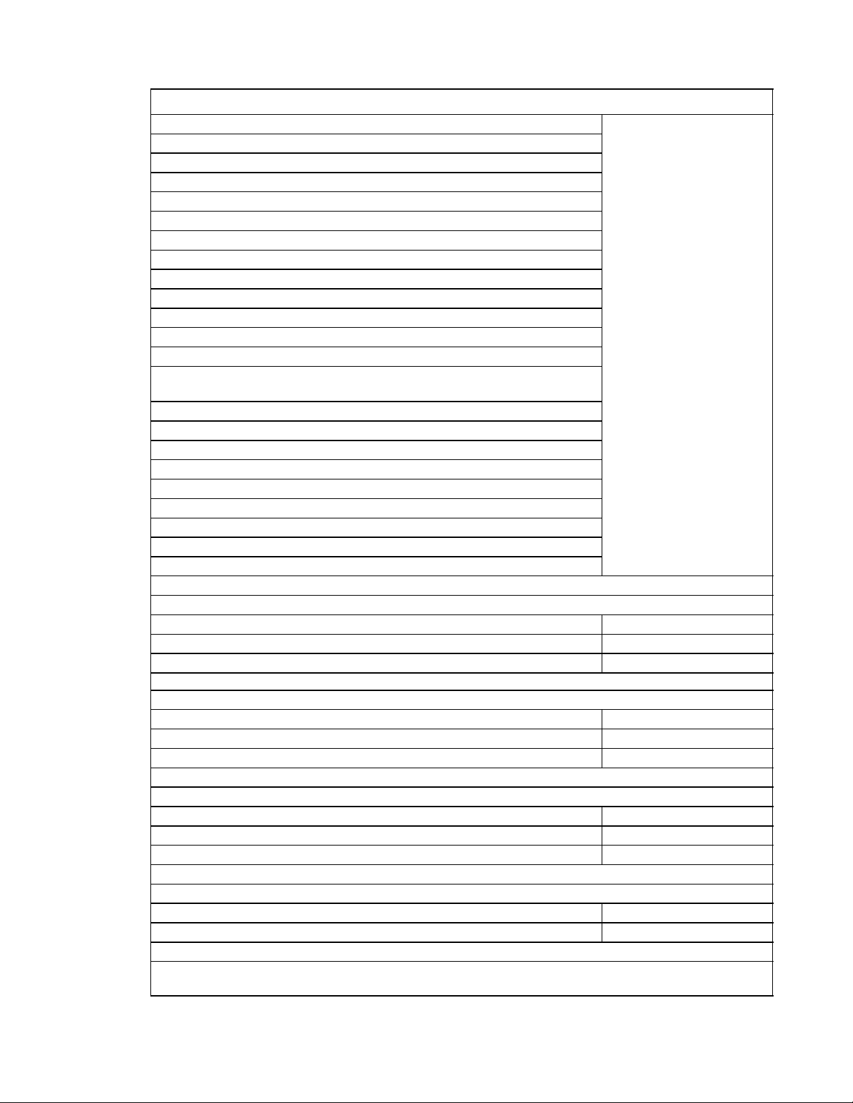
Table 1. Design Data
Unit Description (See *NOTE below)
115V, 60Hz
5-FL Remote Carbonator (3–2–1 Coil Configuration)
6-FL Remote Carbonator (3–2–1 Coil Configuration)
5-Fl Integral Carbonator
6-Fl Integral Carbonator
5-Fl Integral Carbonator W/Syrup Pumps
6-Fl Integral Carbonator W/Syrup Pumps
230V, 50Hz
5-FL Remote Carbonator (3–2–1 Coil Configuration)
6-FL Remote Carbonator (3–2–1 Coil Configuration) Unit Part No.
5- Fl Integral Carbonator (See Nameplate)
6-Fl Integral Carbonator
6-Fl Integral Carbonator, Low-carb No. 4 dispensing valve
(CE approved)
5-Fl Integral Carbonator W/Syrup Pumps
6-Fl Integral Carbonator W/Syrup Pumps
230V, 60Hz (High-Torque Start)
5-FL Remote Carbonator (3–2–1 Coil Configuration)
6-FL Remote Carbonator (3–2–1 Coil Configuration)
5- Fl Integral Carbonator
6-Fl Integral Carbonator
5-Fl Integral Carbonator W/Built-In Syrup Pumps
6-Fl Integral Carbonator W/Built-In Syrup Pumps
Weights (approx):
Integral (Built-In) Carbonator Unit 141 Pounds
Remote Carbonator Unit (3–2–1 Coil Configuration) 121 Pounds
Ice Bank Weight 32 Pounds
Unit Capacity:
Water Tank (No Ice Bank) 10 Gallons
Integral Carbonator Water Pump 100 GPH
Integral Carbonator Water Tank Reserve 52 0z
Overall Dimensions:
Width 18 inches
Height 26 inches
Depth 24.5 inches
Dispensing Rate:
Four 12-oz Drinks/Min @ 40° F or below in 75° F Ambient **225
Four 12-oz Drinks/Min @ 40° F or below in 90° F Ambient **100
**NOTE: Number of 12-oz drinks dispensed 40F or below (Starting With
Stabilized Ice)
*NOTE: The five and six-flavor Remote Carbonator Dispensers require a remote carbonator be connected
to the Dispensers to provide carbonated water. The five and six-flavor Integral Dispensers have an integral
(built-in) carbonator that provides carbonated water for the Dispensers.
560003094 2
Page 6
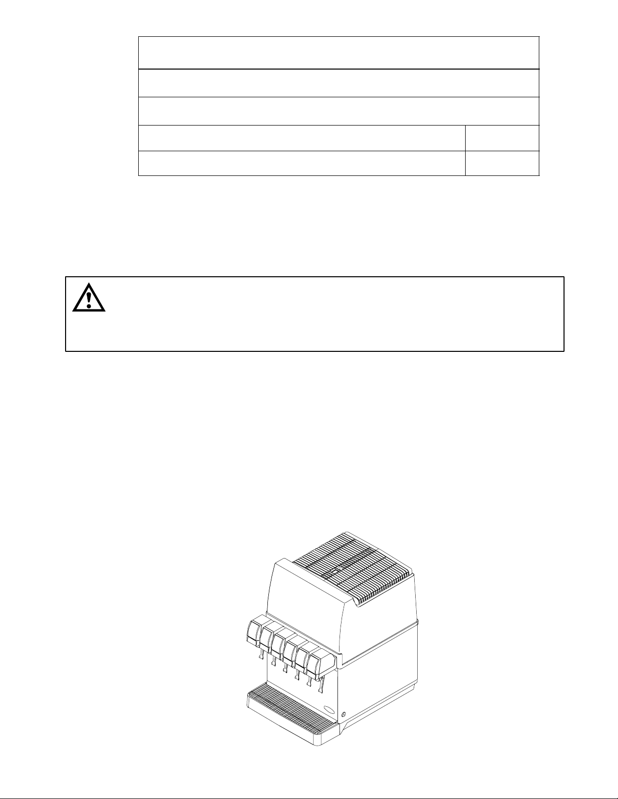
Table 1. Design Data (cont’d)
Refrigeration System Refrigerant Requirement (R-134A) 6.875 oz
Ambient Operating Temperature 40° F to 110° F
Electrical Requirements:
Operating Voltage See Unit
Nameplate
Current Draw See Unit
Nameplate
IMPORTANT: To the user of this manual - This manual is a guide for installing this equipment. Refer to
table of contents for page location of detailed information pertaining to questions that arise during
installation of this equipment.
These Dispensers (hereafter referred to as Units) must be installed and serviced by a qualified Service Person.
These Units contain no User serviceable parts.
CAUTION: Before shipping, storing, or relocating Unit, syrup systems must be sanitized
and all sanitizing solution must be purged from syrup coils. All water must be purged from
carbonated and plain water systems and ice bank melted and all water drained from water
tank. A freezing ambient environment will cause residual water remaining inside Unit to freeze
resulting in damage to internal components.
Unit Description
The Units are compact, lightweight and are in three configurations. The first model, either a five or a six-flavor, is
equipped with an integral (built-in) carbonator. The second model, either a five or six-flavor, is equipped with an
integral (built-in) carbonator and built-in syrup pumps to provide syrup to the Unit. The third model, also either a five
or a six-flavor, requires connection to a remote carbonator. The Units may be island-mounted or installed on a front
or rear counter. Their refrigeration assemblies are the 1/3 H.P. drop-in type and are easily removed for service and
maintenance. Adjustable water flow regulators and syrup flow regulators, located on the dispensing valves, are
easily accessible to control water flow rate of the dispensing valve and Water-to-Syrup “Ratio” of the dispensed
product. The only requirements for operation are installation of the Unit on a countertop, installation of LooseShipped Parts, connection to a remote carbonator for the model requiring connection to a remote carbonator, connections to plain water and syrup supplies, adjustment of CO
cal outlet with proper electrical requirements, and adjusting dispensing valves water and syrup flow regulators for
proper water flow rate and Water-to Syrup “Ratio” of the dispensed product.
regulators, plugging Unit power cord into an electri-
2
GLACIER SIX-FLAVOR UNIT SHOWN
3 560003094
Page 7

THEORY OF OPERATION
NOTE: Refer to Figure 1 for optional dispensing valves dispensing configurations. For Units with integral
(built–in) carbonators (see Figure 3 and 4) and Units with integral (built–in) carbonators and syrup pumps
(see Figure 5). The five-flavor Units may be configured to dispense all carbonated and no still (noncarbonated) drinks or four carbonated and one noncarbonated drink. The six-flavor Units may be configured to
dispense five carbonated and one noncarbonated drinks, four carbonated and two noncarbonated drinks,
or six carbonated and no non-carbonated drinks.
UNITS WITH INTEGRAL (BUILT-IN) CARBONATORS
Standard Units with Integral (Built-In Carbonators. (see Figure 4)
A syrup tanks system or a bag–in–box syrup system may be connected to these Units to provide syrup supply to
the Units. Plain water enters the integral (built-in) carbonator carbonated water tank and is carbonated by regulated
CO2 gas pressure also entering the tank. When dispensing valve is opened, syrup is pushed through the Unit cooling coils, and on to the dispensing valve. Carbonated water tank CO
from the tank to the dispensing valve. Syrup and carbonated water meet simultaneously at the dispensing valve
resulting in a carbonated drink being dispensed. A still (noncarbonated) drink is dispensed in the same manner as
the carbonated drink except plain water is substituted for carbonated water.
gas head pressure pushes carbonated water
2
Dispenser P/N 475136102 (Six-Flavor Unit with Integral (Built-In) Carbonator with Low-Carb No. 4 Dispensing
Valve).) See Figure 3
This Unit operates in much the same way as the standard Units with integral (built-in) carbonators
(See Figure 4). No. 4 dispensing valve is set up to dispense a low-carb drink by connecting a low-carb remote carbonator to the No. 4 dispensing valve water inlet line or plain water may be connected to the water line to dispense
a still (non-carbonated) drink.
UNITS WITH INTEGRAL (BUILT-IN) CARBONATORS AND SYRUP PUMPS
(See Figure 5)
A CO2 cylinder delivers carbon dioxide (CO2) gas through an adjustable CO2 regulator to the syrup pumps and
also the integral (built-in) carbonator located inside the Unit. Plain water enters the carbonator carbonated water
tank and is carbonated by regulated CO2 gas pressure also entering the tank. Opening one of the dispensing
valves causes the CO2 operated syrup pump associated with that valve to operate which pumps syrup from the
syrup bag-in-box, through the Unit cooling coil, and on to the dispensing valve. Carbonated water tank CO
gas
2
head pressure pushes carbonated water from the tank to the dispensing valve. Syrup and carbonated water meet
simultaneously at the dispensing valve resulting in a carbonated drink being dispensed. A still (non-carbonated)
drink is dispensed in the same manner as the carbonated drink except plain water is substituted for carbonated
water.
UNITS WITH 3–2–1 COIL CONFIGURATIONS (REQUIRING CONNECTION TO REMOTE
CARBONATORS)
(See Figure 6)
The three Unit water inlet lines may be connected to either plain water or carbonated water (remote car
bonito) source lines. Plain or carbonated water connected to No. 1 water inlet line will allow No. 5 valve to dispense
either a still (noncarbonated) or a carbonated drink. Plain or carbonated water connected to No. 2 water inlet line
will allow No. 3 and No. 4 valves to dispense either still (noncarbonated) or carbonated drinks. Plain or carbonated
water connected to No. 3 water inlet line will allow No. 1, 2, and No. 6 valves to either dispense still (noncarbonated) or carbonated drinks. A syrup tank system or a syrup bag–in–box/syrup pump system may be connected to
the Unit to provide syrup supply to the Unit.
560003094 4
Page 8
5
FIVE VALVES CARB
NO VALVES NON-CARB
61
1
6
5
FOUR VALVES CARB
NO. 3 VALVE NON-CARB
5-FLAVOR WITH INTEGRAL (BUILT-IN) CARBONATOR
PART NO:
426015
426025
475015
475025
476015
476025
2
6
4
FIVE VALVES CARB
NO. 4 VALVE NON-CARB
6-FLAVOR WITH INTEGRAL (BUILT-IN) CARBONATOR
46
32
5
FOUR VALVES CARB
NO. 3 & 4 VALVES NON-CARB
62
5
FIVE VALVES CARB
NO. 4 VALVE CUSTOM
INDIVIDUAL SUPPLY COIL
52 6
3
4
SIX VALVES CARB
NO VALVES NON-CARB
PART NO:
426016
426026
475016
475026
476016
476026
6-FLAVOR UNIT (P/N 475136102) WITH INTEGRAL (BUILT-IN) CARBONATOR
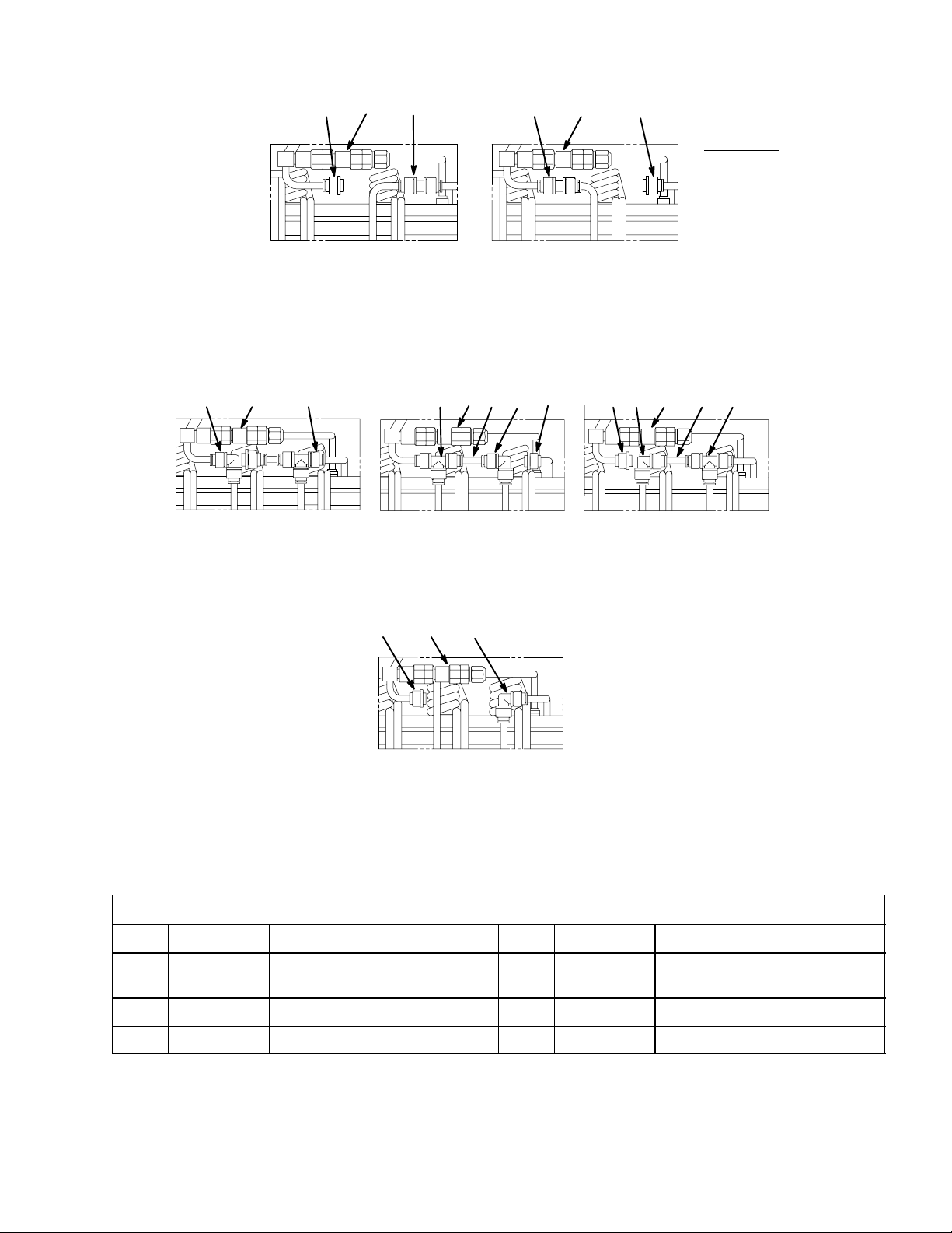
Parts Identification for Optional Configurations
Item P/N Description Item P/N Description
1 2535 Connector, Straight, Plain wa-
ter
2 2483 Connector, Elbow, Plain water 5 2649 Plug Assembly
3 2350 Tube, Straight, S/S 6 311765-001 Dual Check Valve Assembly
FIGURE 1. OPTIONAL CONFIGURATIONS
NOTE: 1. Illustrations show view of tubing connections on top front of the water tank.
2. Connections require lubrication prior to assembly.
4 2484 Connector, Tee
5
560003094
Page 9
OPERATING CONTROLS
DISPENSING VALVE LEVER: The dispensing valve lever, located on the bot-
tom of the dispensing valve, needs only to be pressed with a cup or glass to
dispense product.
KEY-LOCK SWITCH: The key-lock switch, located on the
bottom right side of the dispenser, prevents operation of the
dispensing valves when switch is in the “OFF” position.
This key-lock switch does not affect operation of the
refrigeration system.
CONTROL BOARD POWER SWITCH: The control board
power switch is located on the top of the refrigeration
assembly and is accessible through a hole in top of the
hood. THIS SWITCH IS AN ON-OFF SWITCH AND
CONTROLS ONLY THE 24 VAC LOW VOLTAGE
POWER SOURCE TO THE CONTROL BOARD.
HIGH VOLTAGE IS STILL PRESENT INSIDE THE
DISPENSER. USE CAUTION, UNPLUG UNIT
POWER CORD FROM ELECTRICAL OUTLET
BEFORE PERFORMING INTERNAL
MAINTENANCE ON THE DISPENSER.
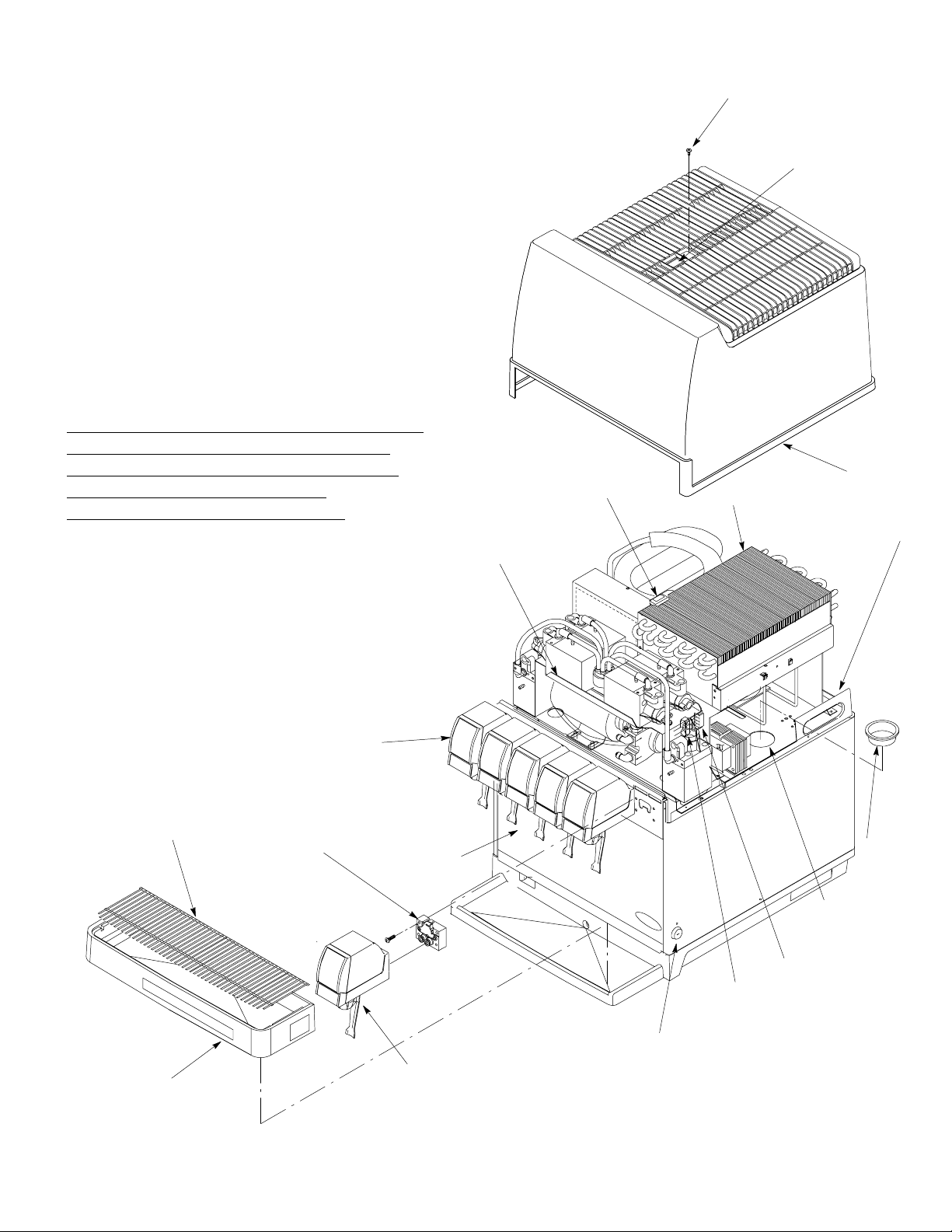
INTEGRAL CARBONATOR
PUMP & MOTOR ASSEMBLY
CONTROL BOARD
POWER SWITCH
HOOD SCREW
REFRIGERATION
POWER SWITCH
ACCESS HOLE
HOOD
CONDENSER
REFRIGERATION
DECK LIFTING HANDLES
CUP REST
DRIP TRAY
DISPENSING
VALVES (6)
VALVE MOUNTING
BLOCK
FRONT PANEL
KEY-LOCK SWITCH
DISPENSING VALVE
LEVER
FIGURE 2. PARTS IDENTIFICATION (SIX-FLAVOR UNIT SHOWN)
FILL HOLE
PLUG
WATER T ANK
FILL HOLE
CONNECTOR
CARBONATOR MOTOR
POWER CORD
560003094 6
Page 10
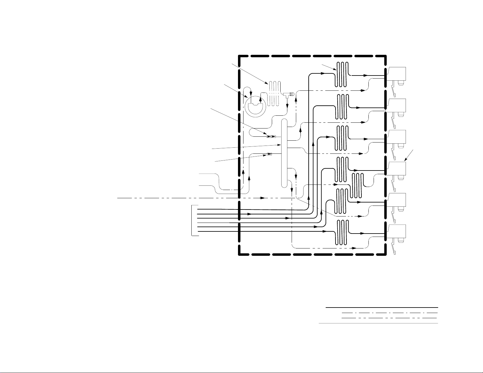
PLAIN WATER
COOLING COIL
SYRUP COIL (6)
7
be a bag–in–box system or a syrup
tanks system
VALVE WATER INLET
NO.4 DISPENSING
(SEE NOTE 2)
DOUBLE LIQUID
CHECK VALVE
CARBONATED
WATER TANK
CO2 CHECK VALVE
PLAIN WATER INLET
CO2 INLET
SYRUP INLETS
(SEE NOTE 1)NOTE 1: The syrup sources may either
WATER PUMP
AND MOTOR
1
2
3
STILL (NON-CARB
OR
LOW-CARB DRINK
4
5
6
NOTE 2: The No. 4 dispensing valve water inlet may be connected
to a low-carb carbonator for a low-carb drink to be dispensed
from No. 4 dispensing valve or the water inlet line may be connected to filtered plain water to dispense a still (non-carbonated)
drink from No. 4 dispensing valve.
560003094
FIGURE 3. FLOW DIAGRAM (SIX-FLAVOR UNIT [P/N 475136102] WITH INTEGRAL (BUILT-IN) CARBONATOR SHOWN)
LINE LEGEND
SYRUP
PLAIN WATER
CARB WATER
CO
2
DISPENSER
Page 11
560003094
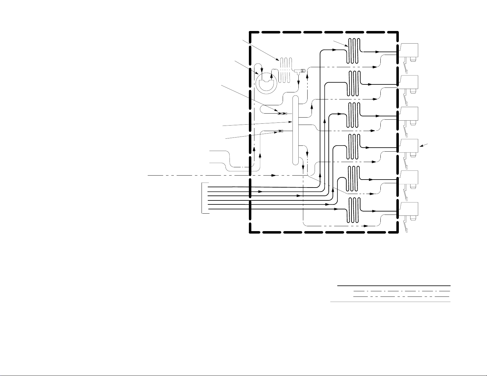
PLAIN WATER
COOLING COIL
SYRUP COIL (6)
8
NOTE 1: The syrup sources may either
be a bag–in–box system or a syrup
tanks system
NO.4 DISPENSING VALVE
PLAIN WATER INLET
DOUBLE LIQUID
CHECK VALVE
CARBONATED
WATER TANK
CO
CHECK VALVE
2
PLAIN WATER INLET
CO2 INLET
SYRUP INLETS
(SEE NOTE 1)
WATER PUMP
AND MOTOR
1
2
3
STILL (NON-
4
CARB) DRINK
5
6
DISPENSER
LINE LEGEND
SYRUP
PLAIN WATER
CARB WATER
CO
2
FIGURE 4. FLOW DIAGRAM (STANDARD SIX-FLAVOR UNIT WITH INTEGRAL (BUILT-IN) CARBONATOR SHOWN)
Page 12
PLAIN WATER
COOLING COIL
WATER PUMP
AND MOTOR
DOUBLE LIQUID
CHECK VALVE
CARBONATED
WATER TANK
SYRUP COIL (6)
1
2
3
9
560003094
NOTE: Syrup sources may either be a
bag–in–box system or a syrup tanks
system
LINE LEGEND
SYRUP
PLAIN WATER
CARB WATER
CO
2
CO2 CHECK VALVE
PLAIN WATER INLET
CO2 INLET
SYRUP INLETS
(SEE NOTE)
4
5
6
SYRUP PUMP (6)
32
1
4
65
CO2 MANIFOLD
DISPENSER
FIGURE 5. FLOW DIAGRAM (SIX-FLAVOR UNIT WITH INTEGRAL CARBONATOR AND BUILT-IN SYRUP PUMPS)
Page 13

560003094
10
NOTE: Syrup sources may either be a
syrup bag–in–box system or a syrup
tanks system
LINE LEGEND
SYRUP
PLAIN OR CARB WATER
WATER
COOLING COIL
(4)
DISPENSER
SYRUP COIL (6)
1
2
3
4
5
6
PLAIN WATER OR
CARBONATED
WATER INLET
LINES
1
2
NO.3 WATER INLET LINE FOR
VALVES NO. 1, 2, AND 6
NO.2 WATER INLET LINE FOR
VALVES NO. 3 AND 4
3
NO.1 WATER INLET LINE
FOR VALVE NO. 5
1
2
4
3
SYRUP INLET LINES
5
(SEE NOTE)
6
FIGURE 6. FLOW DIAGRAM (SIX-FLAVOR UNIT WITH 3–2–1 COIL CONFIGURATION REQUIRING CONNECTION TO REMOTE CARBONATOR)
Page 14

FIGURE 7. WIRING DIAGRAM
56000309411
Page 15

.
.
.
FIGURE 8. CONTROL BOARD DIAGNOSTIC DECAL
.
.
560003094
12
Page 16

INSTALLATION
LOOSE-SHIPPED PARTS
1. After Unit has been unpacked, remove screw securing hood to Unit, then remove hood.
2. Remove Unit front access panel by lifting panel up, then pull out on bottom.
3. Unpack Loose-Shipped Parts. Make sure all items are present and in good condition.
Table 2. Loose-Shipped Parts
Item
No. Part No. Name
1 2488
3094
2 2134
3093
3 2190 Lock, Key 1 1
4 315865000 Drain Hose, 75-in. Long 1 1
5 140133000 Hose Clamp 1 1
6 3915 Cover, Base Opening 1 1
7 3534 Fitting 5 6
8 3297 *Lever, Water (UF-1 Valve) 1 1
*LEVER, WATER (item 8) is optional and is intended to be installed on the UF-1 Dispensing Valve only.
Cup Rest, Black
Cup Rest, Gray
Drip Tray, Black
Drip Tray, Gray
Qty.
5FL
1
1
1
1
Qty.
6FL
1
1
1
1
IDENTIFICATION OF LOOSED-SHIPPED PARTS
1. DRIP TRAY (item 2) to be installed on Unit, then CUP REST (item 1) to be installed in the drip tray.
2. LOCK KEY (item 3) locks and unlocks the keyed lock switch on side of the Unit.
3. DRAIN HOSE (item 4) to be installed on Unit.
4. HOSE CLAMP (item 5) used to secure DRAIN HOSE (item 4) when hose is connected to Unit.
5. Install COVER, BASE OPENING (item 6) in opening located in back of the Unit base if syrup, CO2 and water
source lines and drip tray drain hose will not be routed out through the opening.
INSTALLATION
SELECTING LOCATION
CAUTION: This Unit is intended for indoor installation only. Do not install this Unit in an
outdoor environment which would expose it to the outside elements.
This unit may be island-mounted or installed on a front or rear counter. The counter must be capable of supporting
230 pounds and allow access for syrup, water and CO2 tubing.
Allow sufficient clearance (15 inches vertical) above top of the hood to the nearest obstruction for ventilation and
removal of the hood and the drop-in refrigeration assembly. A total of 42.5 is required above the counter.
The Unit must have 5 inches clearance on both sides and 5 inches clearance on back side.
13
560003094
Page 17

FOR INDOOR USE
ONLY
18 in.
DO NOT PLACE
ANY OBJECT
ON UNIT.
Allow sufficient clearance
(15 vertical) above top of the hood to
the nearest obstruction for ventilation
and removal of the hood and the drop-in
refrigeration assembly. A total of 42.5
is required above the counter.
The Unit must have 5
clearance o n both sides and 5
clearance on back side.
27.5 in.
NAMEPLATE
24.5 in.
POWER CORD
(MAINS CORD)
GFCI (ELCB) OUTLET
Connect to a properly grounded, accessible, dedicated electrical outlet, with GFCI (ELCB) fused at 15 amps (“slow-blow”) or an equivalent
HACR circuit breaker. Electrical supply (Voltage, Hertz) must agree with the equipment nameplate.
ALL ELECTRICAL WIRING MUST CONFORM TO NA TIONAL AND LOCAL ELECTRICAL CODES
SEALING UNIT TO COUNTERTOP
To comply with NSF International (NSF) requirements within the United States, the Unit base must be sealed to the
countertop and all access holes inside of the Unit base must be sealed with permagum or other sealant. Proceed as
follows to seal the Unit base to the countertop.
NOTE: An alternate arrangement to avoid the sealing process would be to install the available 4 Legs,
P/N 314744000. Four of these legs are required.
APPLY SEALANT
TO BASE BOTTOM EDGES.
560003094 14
Page 18

1. Place Unit in operating position on countertop.
2. Tilt Unit up in preparation to install the drip tray DRAIN HOSE (item 4).
3. Connect drip tray drain hose to fitting on drip tray holder. Secure connection with HOSE CLAMP (item 5).
NOTE: Install COVER, BASE OPENING (item 6) in opening located in back of the Unit base if syrup, CO2 and
water source lines and drip tray drain hose will not be routed out through the opening.
4. Route drip tray drain hose under and to the back of the Unit.
5. Tilt the Unit to expose the bottom of the base.
6. Liberally apply a silastic sealant such as Dow Corning RTV 731 or equivalent on the base bottom edges.
NOTE: Do not move the Unit after positioning or the seal will be broken.
7. Lower the Unit into operating position to complete the seal to the countertop.
8. Seal all access holes to the inside of the Unit base with permagum or other sealant after completing installation
of the Unit.
SELECTING SLEEP MODE OPTIONS (UNITS WITH INTEGRAL CARBONATORS)
NOTE: The Unit control board (see Figure 7) is equipped with a sleep mode 3-socket connector and a 2-pin
jumper block which when plugged into the 3-socket connector in different configurations, allows the User to
select the desired “SLEEP MODE” option.
The five and six-flavor Units, with integral carbonators, are factory set to operate in either “MODE 2” or
“MODE 3” option with “SLEEP MODE” active. Please review this setting on the control board and select the
required setting for your installation.
3-SOCKET
CONNECTOR 2-PIN JUMPER BLOCK
MODE 1
(A)
Selecting “Sleep Mode” Option
MODE OPTION
MODE 2
(B)
INPUT
MODE 3
(C)
DESCRIPTION
CONFIGURATION
MODE 1 No Jumper No Sleep Mode W/Plain Water Booster
MODE 2 Input 1 Jumpered Sleep Mode W/Plain Water Booster
MODE 3 Input 2 Jumpered Sleep Mode W/Plain Water Wakeup
Sleep Mode Jumper Option
Mode 1 Option (see illustration A).
If Mode 1 is selected and no jumper block is connected to the 3-socket connector as shown in illustration A, the integral carbonator Unit will switch the agitator motor on to operate continuously. “SLEEP MODE” will not be active but
“PLAIN WATER BOOSTER” will be activated (carbonator water pump starts and increases water pressure to the
plain water valve when valve is activated) only when optional jumper wires are connected between the plain water
valve and the control board. (See ACTIVATING PLAIN WATER PRESSURE BOOSTER OR PLAIN WATER
WAKEUP OPTIONS for instructions to install optional jumper wires.)
15
560003094
Page 19

Mode 2 Option (see illustration B).
If Mode 2 is selected and jumper block is plugged into the 3-socket connector as shown in illustration B, “SLEEP
MODE” and “PLAIN WATER BOOSTER” will be activated. “SLEEP MODE” is entered during periods of refrigeration
compressor and carbonator water pump inactivity. If compressor and carbonator water pump motor have not been
operating (inactive) for ten (10) minutes, the Unit will go into “SLEEP MODE”. While the Unit is in “SLEEP MODE”,
the agitator motor will be cycled on every ten (10) minutes and operate for thirty (30) seconds, then stop. “SLEEP
MODE” will continue until either the refrigeration compressor, carbonator water pump motor, or the plain water valve
become active. Once active, the agitator motor will operate continuously until the refrigeration compressor and the
carbonator water pump have turned off and been inactive for ten (10) minutes. “SLEEP MODE” will again occur.
“PLAIN WATER BOOSTER” (wakes up agitator motor and starts water pump which increases plain water pressure to
the plain water valve) will be active only when optional jumper wires are connected between the plain water valve and
connector on the refrigeration deck. (See ACTIVATING PLAIN WATER PRESSURE BOOSTER OR PLAIN WATER
WAKEUP OPTIONS for instructions to install optional jumper wires.)
Mode 3 Option (see illustration C).
If Mode 2 is selected and jumper block is plugged into the 3-socket connector as shown in illustration B, “SLEEP
MODE” and “PLAIN WATER WAKEUP” will be activated. “SLEEP MODE” is entered during periods of refrigeration
compressor and carbonator water pump inactivity. If compressor and carbonator water pump motor have not been
operating (inactive) for ten (10) minutes, the Unit will go into “SLEEP MODE”. While the Unit is in “SLEEP MODE”,
the agitator motor will be cycled on every ten (10) minutes and operate for thirty (30) seconds, then stop. “SLEEP
MODE” will continue until either the refrigeration compressor, carbonator water pump motor, or the plain water valve
become active. Once active, the agitator motor will operate continuously until the refrigeration compressor and the
carbonator water pump have turned off and been inactive for ten (10) minutes. “SLEEP MODE” will again occur.
“PLAIN WATER WAKEUP” (wakes up agitator motor only and does not start water pump to increase water pressure
to the plain water valve) will be activated only when the optional jumper wires are connected between the plain water
valve and connector on the refrigeration deck. (See ACTIVATING PLAIN WATER PRESSURE BOOSTER OR PLAIN
WATER WAKEUP OPTIONS for instructions to install optional jumper wires.)
FILL WATER TANK AND START REFRIGERATION SYSTEM
1. Loosen screw securing hood to Unit, then lift hood up to remove.
CONTROL BOARD
POWER SWITCH
INTEGRAL CARBONATOR
PUMP AND MOTOR
ASSEMBLY
CARBONATED WATER
TANK SENSOR
CONNECTOR
FILL HOLE
PLUG
WATER TANK
FILL HOLE
DISPENSING
VALVE (6)
560003094 16
CARBONATOR MOTOR
POWER CORD
AND CONNECTOR
Page 20

2. Make sure plug is secure in water tank drain hose.
NOTE: Use low-mineral-content water if a local water problem exists. Do not use distilled or deionized water.
3. Remove fill-hole plug from drop-in refrigeration deck fill hole.
4. Fill water tank with clean water until water runs out of water tank overflow hose into the drip tray.
5. Install fill-hole plug back in the fill hole.
6. Disconnect carbonator tank sensor wiring harness connector from Unit wiring harness mating connector.
7. Make sure control board power switch on top of the refrigeration assembly is in the “OFF” position.
8. Plug Unit power cord into electrical outlet.
9. Place control board power switch in “ON” position. Refrigeration compressor will start after a 2 minute built-in
time delay and start building an ice bank. If water in water bath is above temperature of 60° F, the agitator motor
will not operate until refrigeration system has cooled the water temperature down to below 60° F. Agitator motor
will then start and operate.
CONNECTING SYRUP TUBING TO UNIT
Units Without Built-In Syrup Pumps.
1. Route the required pieces of 3/8 I.D. syrup tubing (labeled for flavor identification) from syrup source (tank or
Bag-in-Box) up to the back of the Unit. See flow diagram Figure 3 or 6 for the proper connection detail.
2. Connect the labeled syrup source tubing to the matching labeled barbed syrup inlet fittings located behind the
front panel of the Unit. Make sure the flavors are correctly connected. Secure the connections with tubing
clamps. DO NOT CONNECT SYRUP SUPPLIES TO SYRUP SYSTEMS AT THIS TIME.
SYRUP INLET
LINES (4, 5, 6)
SYRUP PUMP ASS’Y
SYRUP TUBING, 5 OR 6
17
SYRUP INLET
LINES (1, 2, 3)
560003094
Page 21

Units With Built-In Syrup Pumps.
(see Figure 4)
1. Route the required pieces of 3/8 I.D. syrup tubing (labeled for flavor identification) from bag-in-boxes syrup
sources up to the back of the Unit. See flow diagram Figure 4 for the proper connection detail.
2. Route labeled syrup tubes under the Unit up behind the front panel to inside of the Unit.
3. Connect the labeled syrup source tubing to matching labeled syrup pumps syrup inlet fittings. Make sure the flavors are correctly connected. Secure the connections with tubing clamps. DO NOT CONNECT SYRUP SUPPLIES TO SYRUP SYSTEMS AT THIS TIME.
CONNECTING CO2 AND PLAIN WATER SOURCES
NOTE: IMI Cornelius Inc. recommends that a water shutoff valve be installed in the plain water supply connected to this system and that the water supply be filtered.
Integral (Built-In) Carbonator Unit Without Syrup Pumps.
1. Route CO2 tube from the CO2 source to the back of the Unit. See flow diagram Figure 3 for the proper connection detail.
2. Route plain water tube from a plain water source shut-off valve to the back of the Unit. Water supply must be
capable of supplying 100 GPH at a pressure not to exceed 50 PSI. A water pressure regulator must be installed
if the pressure exceeds 50 PSI.
3. Connect the plain water tube to the Unit carbonator pump inlet fitting. Seal the connection with a tapered gasket.
4. Connect CO2 tube to Unit CO2 inlet check valve located behind the front panel.
WATER
TUBING
SHUT-OFF
VALVE
CO2 TUBING
Integral (Built-In) Carbonator Unit With Syrup Pumps.
1. Route CO2 tube from the CO2 source to the back of the Unit. See flow diagram Figure 4 for the proper connection detail.
560003094 18
Page 22

2. Route plain water tube from a plain water source shut-off valve to the back of the Unit. Water supply must be
capable of supplying 100 GPH at a pressure not to exceed 50 PSI. A water pressure regulator must be installed
if the pressure exceeds 50 PSI.
3. Connect the plain water tube to the Unit carbonator pump inlet fitting. Seal the connection with a tapered gasket.
4. Connect CO2 tube to Unit CO2 inlet check valve located behind the front panel.
CONNECTING CARBONATED AND PLAIN WATER SOURCES TO 3–2–1 COIL
CONFIGURATION REMOTE CARBONATOR UNIT
1. Route carbonated water tube from the remote carbonator to the back of the Unit. See flow diagram Figure 6 for
the proper connection detail.
2. Route plain water tube (if required) from plain water source to the back of the Unit. This plain water is for any
noncarbonated flavors. See flow diagram Figure 6 for the proper connection detail.
3. Connect carbonated water and plain water tubes to appropriate connections behind the front panel.
CARBONATED
WATER TUBING
PLAIN WATER
TUBING
CONNECTING DRIP TRAY DRAIN HOSE
NOTE: The Unit is equipped with a drip tray drain hose. If desired to utilize the drip tray drain hose, the drip
tray outlet must be drilled out as the outlet is covered with a thin layer of plastic. AFTER DRILLING, MAKE
SURE ALL BURRS ARE REMOVED FROM THE DRILLED HOLE.
The drip tray drain hose should not be routed to a waste container due to sanitation and cleaning problems.
Install drip tray drain hose on Unit as follows: (Refer to table 2, Loose Shipped Parts.)
1. Install drip tray DRAIN HOSE (item 4) on Unit and secure with HOSE CLAMP (item 5).
2. Route the drain hose to a permanent drain such as a floor drain.
3. The drain hose must be attached to the drain to allow a 3 air gap between the drain and the end of the hose. All
connections must comply with local plumbing and health codes.
4. Install the DRIP TRAY (item 2) in the Unit and then install the CUP REST (item 1) on the drip tray.
19
560003094
Page 23

3 AIR GAP
DRIP TRAY
DRAIN HOSE
560003094 20
Page 24

PREPARATION FOR OPERATION
OPENING THE CO
NOTE: Make sure primary and secondary CO2 regulators adjusting screws are turned to the left (counterclockwise) until all tension is relieved from the adjusting screws springs before opening the CO
cylinder shutoff valve.
1. The valve on the CO2 cylinder must be opened slowly. Open the valve until it is open to it’s fullest and
“back-seated”. This prevents any CO2 from leaking around the valve shaft.
2. Check for leaks at all connections. Repair any leaks that are found.
CYLINDER SHUTOFF VALVE AND LEAK CHECKING
2
TURN CCW TO OPEN
VALVE
2
ACTIVATING THE CARBONATOR
UNIT WITH INTEGRAL (BUILT-IN) CARBONATOR AND WITHOUT BUILT-IN SYRUP
PUMPS.
1. Open plain water shut-off to the carbonator. Check for leaks and repair as needed.
2. Pull up on carbonated water tank relief valve (accessible through hole in refrigeration assembly platform)
until water spurts from valve.
SUGAR SYRUP
REGULATOR
PRIMARY CO
REGULATOR
2
DIET SYRUP
REGULATOR
TO CARBONATOR
56000309421
Page 25

3. Adjust CO
regulator for the carbonator at a nominal 70 PSIG. PRESSURE TO THE CARBONATOR
2
MUST NOT EXCEED 80 PSIG.
4. Place control board power switch in “OFF” position.
5. Unplug Unit power cord from electrical outlet.
6. Connect carbonator tank sensor wiring harness connector into Unit wiring harness connector.
7. Plug Unit power cord into electrical
outlet.
8. Place control board power switch in “ON” position. After a 2 minute built-in time delay, refrigeration compressor will start and carbonator pump motor will start when carbonator calls for more
water.
9. Make sure the key-lock switch on the side of the Unit is ON. Dispense from all the dispensing valves until
all air is purged from the system and carbonated water is being dispensing from the valves.
UNIT WITH INTEGRAL (BUILT-IN) CARBONATOR AND WITH BUILT-IN SYRUP PUMPS.
1. Open plain water shut-off to the carbonator. Check for leaks and repair as needed.
2. Pull up on carbonated water tank relief valve (accessible through hole in refrigeration assembly platform)
until water spurts from valve.
3. Adjust CO
regulator for the carbonator at a nominal 70 PSIG. PRESSURE TO THE CARBONATOR
2
MUST NOT EXCEED 80 PSIG.
4. Place control board power switch in “OFF” position.
5. Unplug Unit power cord from electrical outlet.
6. Connect carbonator tank sensor wiring harness connector into Unit wiring harness connector.
PRIMARY CO
REGULATOR
2
TO CARBONATOR
AND SYRUP PUMPS
7. Plug Unit power cord into electrical outlet.
8. Place control board power switch in “ON” position. After a 2 minute built-in time delay, refrigeration compressor will start and carbonator pump motor will start when carbonator calls for more water.
9. Make sure the key-lock switch on the side of the Unit is in the “ON” position. Dispense from all the dispensing valves until all air is purged from the system and carbonated water is being dispensed from the valves.
UNIT REQUIRING CONNECTION TO A REMOTE CARBONATOR.
1. Refer to carbonator manual for proper CO
ingly.
560003094 22
operating pressure. Adjust the primary CO2 regulator accord-
2
Page 26

2. Open the plain water source shut-off to the carbonator. Check for leaks and repair as needed.
3. Plug the remote carbonator power cord into an electrical outlet. The carbonator pump motor will start
when carbonator calls for more water.
4. Make sure the key-lock switch on the side of the Unit is in “ON” position. Dispense from dispensing valves
until all air is purged from the carbonated water system and carbonated water is being dispensed from the
valves.
SUGAR SYRUP
REGULATOR
PRIMARY CO
REGULATOR
2
DIET SYRUP
REGULATOR
TO CARBONATOR
ADJUSTING SUGAR SYRUP TANKS CO2 REGULATOR
Adjust the sugar syrup tank CO2 regulators to 40 PSI for syrup tubing that does not exceed 40 feet.
For syrup tubing that exceeds 40 feet, use the following table to calculate the correct pressure:
Starting Pressure Add for Horizontal Length Add for Vertical Lift
40 PSI 1 PSI/10 feet 1 PSI/2 feet
Based on this formula, a system with 80 feet of horizontal tubing and 10 feet of vertical tubing would require an
operating pressure of 40 PSIG [40 PSI (First 40 feet, horizontal) + 4 PSI (40 additional feet @ 1 PSI per 10 feet,
horizontal) + 5 PSI (10 feet vertical @ 1 PSI for each 2 feet of vertical lift)] = 49 PSI.
To adjust the CO
regulator, loosen the lock nut, then turn the adjusting screw clockwise until the gauge regis-
2
ters the desired pressure. Tighten the lock nut when the desired pressure is set.
ADJUSTING DIET SYRUP TANK CO2 REGULATOR
Adjust the diet syrup tank CO2 regulators to 10 PSI for syrup tubing that does not exceed 30 feet. Diet syrup
tubing that is longer than 30 feet may require a slightly higher pressure, but in any case, do not exceed
12 PSI maximum. Excessive CO2 pressure will cause the diet syrup to carbonate and result in foaming of the
product.
To adjust the CO
regulator, loosen the lock nut, then turn the adjusting screw clockwise until the gauge
2
registers the desired pressure. Tighten the lock nut after the desired pressure is set.
ADJUSTING SYRUP PUMPS CO2 REGULATOR (UNITS WITH INTEGRAL BUILT-IN
CARBONATOR AND BUILT-IN SYRUP PUMPS)
CO2 pressure to operate Units equipped with an integral (built-in) carbonator and built-in syrup pumps is
provided by a CO2 regulator in the system. The CO2 regulator provides regulated CO2 pressure to both the
integral carbonator and also the built-in syrup pumps. Adjust the CO2 regulator to 70 PSI. DO NOT EXCEED
MAXIMUM PRESSURE SPECIFIED ON THE SYRUP PUMPS.
56000309423
Page 27

To adjust the CO
regulator, loosen the lock nut, then turn the adjusting screw clockwise until the gauge
2
registers the desired pressure. Tighten the lock nut after the desired pressure is set.
MEASURING AND ADJUSTING DISPENSING VALVE CARBONATED WATER
FLOW RATE
1. Remove cover from the dispensing valve by lifting the front cover up 1/4 inch and pulling forward.
2. Install syrup diversion tube assembly on the dispensing valve by pushing rubber end of the syrup diversion
tube onto the syrup outlet of the inner nozzle.
3. Measure the water flow rate by dispensing water into a graduated cup for a set period of time.
NOTE: Adjusting screw stops are built into the valve to prevent leakage when the screws are adjusted
too far clockwise. Stop adjusting clockwise when turning resistance increases. Turn the screw counterclockwise 1–1/2 turns after the stop are contacted.
4. Turn the water flow regulator adjusting screw to the left (counterclockwise) to decrease the water flow rate
or turn the adjusting screw to the right (clockwise) to increase the water flow rate, then recheck the flow
rate. Adjustments should be no more than 1/4 turn at a time.
5. Remove syrup diversion tube from the dispensing valve, then install cover on the dispensing valve.
Counterclockwise
to Decrease
Clockwise
to Increase
WATER FLOW
REGULATOR
SYRUP FLOW
REGULATOR
INNER NOZZLE
NOZZLE
SYRUP DIVERSION
TUBE
RATIO CUP
ADJUSTING DISPENSING VALVE WATER-TO-SYRUP “RATIO” OF DISPENSED
PRODUCT
NOTE: Make sure the dispensing valve water flow rate is as desired before adjusting the valve for Water-to-Syrup ‘‘Ratio’’ (Brix) of the dispensed product.
560003094 24
Page 28

Adjust Water–to–Syrup “Ratio” (Brix) of the dispensed product by using ratio cup (P/N 311100000) and syrup
diversion tube assembly (P/N 319540000) as follows:
1. Remove cover from the dispensing valve by lifting front cover up 1/4 inch and pulling forward.
2. Install syrup diversion tube assembly on the dispensing valve by pushing the rubber end of the syrup diversion tube onto the syrup outlet of the inner nozzle.
Notice: Refer to syrup manufacturer’s recommendations on syrup package for water-to-syrup ratio.
3. Dispense enough to fill syrup diversion tube with syrup.
4. Hold large chamber of the ratio cup under the dispensing valve nozzle. Place free end of the syrup diversion tube into the syrup chamber marked for the proper ratio. Dispense approximately 6 ounces of water
into the ratio cup. Water and syrup levels should be even in cup.
Note: Adjusting screw stops are built into the valve to prevent leakage when the screws are adjusted
clockwise too much. Stop adjusting clockwise when turning resistance increases. Turn the screw
counterclockwise 1–1/2 turns after the stop are contacted.
5. Adjusting Syrup Flow Regulator – If water and syrup levels are uneven in the ratio cup, adjust by
turning the dispensing valve syrup flow regulator adjusting screw labeled SYRUP as follows.
A. For less syrup, turn the adjusting screw counterclockwise no more than 1/4 turn at a time.
B. For more syrup, turn the adjusting screw clockwise no more than 1/4 turn at a time.
6. Repeat water-to-syrup ratio test and adjust syrup flow regulator as many times as necessary until proper
ratio of dispensed drink is achieved.
7. Remove syrup diversion tube assembly from dispensing valve.
8. Install dispensing valve front cover.
56000309425
Page 29

THIS PAGE LEFT BLANK INTENTIONALLY
560003094 26
Page 30

TROUBLESHOOTING
IMPORTANT: Only a service person should service internal components or electrical wiring.
WARNING: Disconnect electrical power to the Unit to prevent personal injury before
attempting any electrical repairs to the internal components. If repairs are to be made to
one of the syrup systems, disconnect applicable syrup tank, then bleed system pressure
before proceeding. If repairs will be made to the CO
electrical power to the carbonator, shut-off CO
before proceeding.
TROUBLESHOOTING POST-MIX SYSTEM
Trouble Probable Cause Remedy
or carbonated water systems, disconnect
2
and water supplies, then bleed systems pressure
2
ADJUSTMENT OF
DISPENSING VALVE SYRUP
FLOW REGULATOR DOES
NOT INCREASE TO DESIRED
WATER -TO-SYRUP “RATIO”.
ADJUSTMENT OF
DISPENSING VALVE SYRUP
FLOW REGULATOR DOES
NOT DECREASE TO
DESIRED WATER -TO-SYRUP
“RATIO.
A. No syrup supply. A. Replenish syrup supply.
B. Syrup supply container not
securely connected into
B. Securely connect syrup supply
container into syrup system.
system.
C. Syrup Tanks System.
Syrup tanks CO2 regulator out
C. Adjust syrup tanks CO
as instructed.
of adjustment.
Syrup Bag-in-Box System.
Syrup pumps CO2 regulator
Adjust pumps CO2 regulator as
instructed.
out of adjustment.
D. Improper Baume of syrup. D. Replace syrup supply.
E. Inoperative dispensing valve
syrup flow control.
F. Tapered washer inside tube
swivel nut connection distorted
E. Repair dispensing valve syrup
flow control.
F. Replace tapered gasket. Make
sure it seats properly.
from being overtightened
restricting syrup flow.
A. Dirty or inoperative dispensing
valve syrup flow control.
A. Disassemble and clean
dispensing valve syrup flow
control.
regulator
2
DISPENSED PRODUCT
CARBONATION TOO LOW.
A. Carbonator CO
of adjustment for existing
regulator out
2
A. Adjust carbonator CO
As instructed.
regulator.
2
water conditions or
temperature.
B. Air in carbonator water tank. B. Vent air out of carbonator water
tank through relief valve. Open
No. 1 dispensing valve to make
carbonator water pump cycle on.
C. Water, oil, or dirt, in CO
supply.
2
C. Remove contaminated CO
Clean CO
system (lines,
2
2.
regulator, etc.) using a mild
detergent. Install a clean CO
2
supply.
56000309427
Page 31

Trouble RemedyProbable Cause
DISPENSED PRODUCT
COMES OUT OF
A. Oil film or soap scum in cups
or glasses.
A. Use clean cups or glasses.
DISPENSING VALVE CLEAR
BUT FOAMS IN CUP OR
GLASS.
B. Ice used for finished drink is
sub-cooled.
B. Do not use ice directly from
freezer. Allow ice to become “wet”
before using. (Refer to following
NOTE.)
NOTE: Crushed ice also causes dispensing problems. When finished drink hits sharp edges of ice,
carbonation is released from dispensed drink.
DISPENSED PRODUCT
PRODUCES FOAM AS IT
LEAVES DISPENSING VALVE.
A. Recovery rate of refrigeration
system exceeded, ice bank
depleted.
B. Carbonator CO2 regulator
pressure too high for existing
A. Allow ice bank to recover.
B. Reduce carbonator CO2 regulator
pressure settings.
water conditions or
temperature.
C. Syrup Tanks System.
Syrup over-carbonated with
CO2 as indicated by bubbles in
inlet syrup lines leading to unit.
C. Remove syrup tanks quick
disconnects. Relieve tank CO
pressure, shake tank vigorously,
then relieve tank CO2 pressure as
many times as necessary to
remove over-carbonation.
2
D. Dispensing valve restricted or
dirty.
E. Tapered gasket inside
carbonated water line swivel
nut connector distorted
restricting carbonated water
flow.
F. Dirty water supply. F. Check water filter. Replace
NO PRODUCT DISPENSED. A. Dispensing valves keyed
lock-out switch in “OFF”
position.
B. No electrical power to Unit. B. Plug in Unit power cord or check
C. Disconnected dispensing
valves power cord.
D. Disconnected or broken wiring
to dispensing valve.
E. Inoperative transformer or
dispensing valve solenoids.
D. Sanitize syrup system as
instructed in Service and
Maintenance Manual.
E. Replace tapered gasket. Make
sure it is properly seated.
cartridge.
A. Place keyed lock-out switch in
“ON” position.
for blown power fuse or tripped
circuit breaker.
C. Connect dispensing valves power
cord.
D. Connect or replace wiring.
E. Replace inoperative part.
ONLY CARBONATED WATER
DISPENSED.
A. Syrup supply container not
securely connected into syrup
system.
B. No syrup supply. B. Replenish syrup supply.
560003094 28
A. Securely connect syrup supply
container into syrup system.
Page 32

Trouble RemedyProbable Cause
ONLY CARBONATED WATER
DISPENSED. (cont’d)
C. Syrup Bag-in-Box System.
Inoperable syrup pump.
Syrup Tanks System.
Syrup tanks CO
regulator not
2
properly adjusted.
D. Inoperable dispensing valve. D. Repair dispensing valve.
E. Dispensing valve syrup flow
control not properly adjusted.
ONLY SYRUP DISPENSED. A. Water inlet supply line shutoff
valve closed.
B. Carbonator not operating. B. Restore carbonator operation.
C. CO
regulator not properly
2
adjusted.
DISPENSED PRODUCT
CARBONATION TOO LOW.
A. Carbonator CO
of adjustment for existing
regulator out
2
water conditions or
temperature.
B. Air in carbonated water tank. B. Vent air from carbonated water
C. Replace inoperable syrup pump.
Adjust syrup tanks CO
regulator
2
as instructed.
E. Adjust dispensing valve syrup
flow control (Water-to-Syrup
“Ratio”) as instructed.
A. Open water inlet supply line
shutoff valve.
C. Adjust CO
regulator as
2
instructed.
A. Adjust carbonator CO
regulator
2
as instructed.
tank by dispensing from No. 1
dispensing valve to make
carbonator water pump motor
cycle on.
NO PRODUCT DISPENSED
FROM ALL DISPENSING
VALVES.
C. Water, oil or dirt in CO
supply. C. Have service person remove
2
contaminated CO
clean CO
system (lines,
2
supply, then
2
regulator, etc.) using a mild
detergent. Install a clean CO
2
supply.
A. Dispensing valves keyed
lock-out switch in “OFF”
A. Place keyed lock-out switch in
“ON” position.
position.
B. No electrical power to Unit. B. Plug in Unit power cord or check
for blown power fuse or tripped
circuit breaker.
C. Dispensing valves power cord
disconnected.
D. Disconnected or broken wiring
C. Connect dispensing valves power
cord.
D. Connect or replace wiring.
to dispensing valve.
E. Inoperative transformer or
E. Replace inoperative part.
valve solenoids.
56000309429
Page 33

TROUBLESHOOTING CARBONATOR
Trouble Probable Cause Remedy
UNIT INTEGRAL CARBONATOR
CARBONATOR NOT
A. CO2 supply depleted. A. Replenish CO2 supply.
OPERATING.
B. Water supply to carbonator
B. Correct water supply problem.
disrupted. Control board has
shut down (5-minute max
operating time).
C. Carbonated water tank water
level probe electrical wiring
C. Connect electrical wiring to water
level probe (see NOTE).
disconnected.
D. Carbonator electrical fuse on
control board blown. (PLACE
D. Replace fuse (5-amp slo-blow
max).
CONTROL BOARD POWER
SWITCH IN “OFF” POSITION
BEFORE REPLACING
FUSE).
E. Inoperative carbonated water
E. Replace probe (see NOTE.)
tank water level probe.
F. Inoperative carbonator pump
F. Replace pump or motor.
or motor.
G. Inoperative control board. G. Replace control board.
NOTE: After completing repairs, place control board power switch (on top of Unit) in “OFF” position,
then place switch back into “ON” position to restart the Unit.
UNIT CONNECTED TO REMOTE CARBONATOR
Trouble Probable Cause Remedy
CARBONATOR NOT
A. Carbonator not operating. A. Refer to manual provided with
OPERATING.
TROUBLESHOOTING REFRIGERATION SYSTEM
Trouble Probable Cause Remedy
REFRIGERATION
A. Ice bank sufficient. A. No refrigeration called for.
COMPRESSOR DOES NOT
OPERATE.
B. No water in water tank. B. Fill water tank with water as
C. Control board power switch on
top of Unit in “OFF” position.
D. Unit power cord unplugged, or
drop-in refrigeration assembly
power cord unplugged.
E. Ice temperature sensor
electrically disconnected.
your carbonator.
instructed.
C. Place control board power switch
in “ON” position (will be a built-in
2-minute time delay before
refrigeration compressor starts).
D. Plug in power cord.
E. Electrically connect or replace
inoperable sensor.
F. No power source (blown fuse
or tripped circuit breaker).
560003094 30
F. Replace fuse or reset circuit
breaker. (NOTE: Fuse or circuit
breaker are not part of unit).
Page 34

Trouble RemedyProbable Cause
REFRIGERATION
COMPRESSOR DOES NOT
OPERATE. (cont’d)
G. Low voltage. G. Voltage must be at least 103 volts
(115 VAC unit) or 208 (230 VAC
unit) at compressor terminal when
compressor is trying to start.
H. Loose, disconnected, or
broken wiring.
I. Overload protector cut out;
overheated compressor.
Condenser fan motor not
operating as required.
H. Tighten connections or replace
broken wiring.
I. Compressor will cool enough to
restart. Do not overdraw cooling
capacity of Unit. Refer to
“CONDENSER FAN MOTOR
NOT OPERATING” in this
section.
J. Inoperative overload protector
J. Replace inoperative part.
or start relay.
K. Inoperative ice bank probe. K. Replace ice bank probe.
L. Inoperative control board. L. Replace control board.
NOTE: During normal operation, if carbonator or refrigeration compressor have not operated for
10-minutes, Unit will go into “SLEEP TIME”. While Unit is in “SLEEP TIME”, agitator motor will operate
every 10 minutes for 30 seconds, then stop. “SLEEP TIME” will continue until either the refrigeration
compressor or the carbonator motor start, then agitator motor will operate continuously until both
compressor and carbonator motor have been off for 10 minutes. “SLEEP TIME” cycle will again occur.
COMPRESSOR WILL NOT
STOP AFTER SUFFICIENT
A. Ice bank probe location
incorrect.
A. Place probe in proper location.
ICE BANK IS PRODUCED.
COMPRESSOR OPERATES
CONTINUOUSLY BUT DOES
NOT FORM SUFFICIENT ICE
BANK.
AGITATOR MOTOR NOT
OPERATING.
B. Ice temperature sensor
B. Replace ice temperature sensor.
inoperative.
C. Control board inoperative. C. Replace control board.
A. Cooling capacity is exceeded
by overdrawing.
B. Unit located in excessively hot
area or air circulation through
condenser coil is restricted.
A. Water bath temperature above
60° F.
A. Reduce amount of drinks drawn
per given time.
B. Relocate Unit or check and if
necessary, clean condenser coil
as instructed.
A. Water bath temperature must be
below 60° F in order for the
agitator motor to operate.
B. Agitator motor in “SLEEP
B. See NOTE.
TIME” mode.
C. No power source (blown fuse
or tripped circuit breaker).
C. Replace fuse or reset circuit
breaker. (NOTE: Fuse or circuit
breaker are not part of the
Unit).
D. Agitator motor propeller
D. Remove obstruction.
obstructed.
E. Low voltage. E. Voltage must be at least 103 volts
(115 VAC Unit) or 208 (230 VAC
Unit) at compressor terminals
when compressor is trying to
start.
56000309431
Page 35

Trouble RemedyProbable Cause
AGITATOR MOTOR NOT
OPERATING. (cont’d)
F. Loose, disconnected, or
broken wiring.
F. Tighten connections or replace
broken wiring.
G. Inoperative agitator motor. G. Replace agitator motor.
NOTE: During normal operation, if carbonator or refrigeration compressor have not operated for
10-minutes, Unit will go into “SLEEP TIME”. While Unit is in “SLEEP TIME”, agitator motor will operate
every 10 minutes for 30 seconds, then stop. “SLEEP TIME” will continue until either the refrigeration
compressor or the carbonator motor start, then agitator motor will operate continuously until both
compressor and carbonator motor have been off for 10 minutes. “SLEEP TIME” cycle will again occur.
560003094 32
Page 36

WARRANTY
IMI Cornelius Inc. warrants that all equipment and parts are free from defects in material and workmanship under normal use and service. For a copy of the warranty applicable to your Cornelius, Remcor or Wilshire product, in your country, please write, fax or telephone the IMI Cornelius office nearest you. Please provide the
equipment model number, serial number and the date of purchase.
IMI Cornelius Offices
AUSTRALIA P.O. 210, RIVERWOOD, NSW 2210, AUSTRALIA (61) 2 533 3122 FAX (61) 2 534 2166
AM LANGEN FELDE 32 A-1222 VIENNA, AUSTRIA (43) 1 233 520 FAX (43) 1-2335-2930
AUSTRIA
BOSKAPELLEI 122 B-2930 BRAASCHAAT, BELGIUM (32) 3 664 0552 FAX (32) 3 665 2307
BELGIUM
RUA ITAOCARA 97 TOMAS COELHO RIO DE JANEIRO, BRAZIL (55) 21 591 7150 FAX (55) 21 593 1829
BRAZIL
ENGLAND
TYTHING ROAD ALCESTER WARWICKSHIRE, B49 6 EU, ENGLAND (44) 789 763 101 FAX (44) 789 763 644
71 ROUTE DE ST. DENIS F-95170 DEUIL LA BARRE PARIS, FRANCE (33) 1 34 28 6200 FAX (33) 1 34 28 6201
FRANCE
GERMANY
GREECE
HONG
ITALY
NEW
SINGAPORE
SPAIN
USA
CARL LEVERKUS STRASSE 15 D-4018 LANGENFELD, GERMANY (49) 2173 7930 FAX (49) 2173 77 438
488 MESSOGION AVENUE AGIA PARASKEVI 153 42 ATHENS, GREECE (30) 1 600 1073 FAX (30) 1 601 2491
KONG 1104 TAIKOTSUI CENTRE 11-15 KOK CHEUNG ST TAIKOKTSUE, HONG KONG (852) 789 9882 FAX (852) 391 6222
VIA PELLIZZARI 11 1-20059 VIMARCATE, ITALY (39) 39 608 0817 FAX (39) 39 608 0814
ZEALAND 20 LANSFORD CRES. P.O. BOX 19-044 AVONDALE AUCKLAND 7, NEW ZEALAND (64) 9 8200 357 FAX (64) 9 8200 361
16 TUAS STREET SINGAPORE 2263 (65) 862 5542 FAX (65) 862 5604
POLIGONO INDUSTRAIL RIERA DEL FONOLLAR E-08830 SANT BOI DE LLOBREGAT BARCELONA, SPAIN (34) 3 640 2839 FAX (34) 3 654 3379
ONE CORNELIUS PLACE ANOKA, MI NNESOTA (612) 421-6120 FAX (612) 422-3255
LD004
4/21/98
56000309433
Page 37

IMI CORNELIUS INC.
CORPORATE HEADQUARTERS:
One Cornelius Place
Anoka, Minnesota 55303-6234
(612) 421-6120
(800) 238-3600
38315221001
 Loading...